SPECIFICATION & INSTALLATION GUIDE FOR MASPORT LE4000 PROVINCIAL BUILT-IN FIRE, NEW ZEALAND MODEL
|
|
|
- Holly Eaton
- 6 years ago
- Views:
Transcription
1 SPECIFICATION & INSTALLATION GUIDE FOR MASPORT LE4000 PROVINCIAL BUILT-IN FIRE, NEW ZEALAND MODEL Manufactured in New Zealand by: GLEN DIMPLEX AUSTRALASIA LIMITED P.O. Box , Botany Auckland 2163 Ph: Fax: Web: Part. No
2 CONTENTS ZERO CLEARANCE BOX (SHIELDING BOX) KIT 2
3 DIMENSIONS: Fig. 1 MODEL D F FF FH FW H W LE4000 PROV BUILT-IN INTRODUCTION In the interest of your safety, building regulatory Authorities in Australia and New Zealand require any woodfire installation to comply with Installation Standard AS/NZS 2918:2001. They may also have local requirements in addition to those in the Standard. Check with your local Building Authority before commencing installation to find if you will require a Building Consent and whether there are extra requirements. This woodfire has been tested to ensure that it will meet the appropriate safety Standard requirements when these instructions are followed. As the safety and emission performance can be affected by altering the appliance, no modifications are allowed without written permission from the manufacturer. The model LE4000 Provincial has been tested to demonstrate compliance with current general emission requirements in New Zealand, but some areas have stricter limits. So check the requirements for your area before purchase or installing the unit. 3
4 WE RECOMMEND THAT THE INSTALLATION OF YOUR MASPORT SOLID FUEL BURNING APPLIANCE BE CARRIED OUT BY A QUALIFIED INSTALLATION TECHNICIAN. LE4000 PROVINCIAL MODEL HAS AIR RECIRCULATING FAN WHICH MUST BE INSTALLED AND ALL ELECTRICAL WORK BE CARRIED OUT BY A LICENSED ELECTRICIAN. REFER DETAILED INSTRUCTIONS FOR INSTALLATION OF FAN FOR THIS MODEL ON PAGE 14. IN SOME REGIONS POWER POINTS ARE NOT PERMISSIBLE WITHIN THE FLOOR PROTECTOR AREA, PLEASE CHECK WITH YOUR LOCAL AUTHORITY. IF THE SUPPLY CORD IS DAMAGED, IT MUST BE REPLACED BY THE MANUFACTURER OR ITS SERVICE AGENT OR A SIMILARY QUALIFIED PERSON IN ORDER TO AVOID ELECTRICAL HAZARD. WARNING: THE APPLIANCE AND FLUE SYSTEM MUST BE INSTALLED IN ACCORDANCE WITH AS/NZS 2918:2001 AND THE APPROPRIATE REQUIREMENTS OF THE REVELANT BUILDING CODE OR CODES. WARNING: APPLIANCES INSTALLED IN ACCORDANCE WITH THIS STANDARD MUST COMPLY WITH THE REQUIREMENTS OF AS/NZS 4013 WHERE REQUIRED BY THE REGULATORY AUTHORITY, I.E. THE APPLIANCE SHALL BE IDENTIFIABLE BY A COMPLIANCE PLATE WITH THE MARKING TESTED TO AS/NZS ANY MODIFICATION OF THE APPLIANCE THAT HAS NOT BEEN APPROVED IN WRITING BY THE TESTING AUTHORITY IS CONSIDERED TO BE IN BREACH OF THE APPROVAL GRANTED FOR COMPLIANCE WITH AS/NZS LE4000 PROVINCIAL APPLIANCES CAN NOT BE FITTED WITH WATER HEATING DEVICE SUCH AS WATER BOOSTER. CAUTION : PLEASE ENSURE THAT ONLY COMPONENTS APPROVED BY GLEN DIMPLEX AUSTRALASIA LTD ARE USED FOR INSTALLATION, as substitutes may adversely affect performance and might nullify compliance with the requirements of AS/NZS 2918:2001. MIXING OF APPLIANCE OR FLUE SYSTEM COMPONENTS FROM DIFFERENT SOURCES OR MODIFYING THE DIMENSIONAL SPECIFICATION OF COMPONENTS MAY RESULT IN HAZARDOUS CONDITIONS. WHERE SUCH ACTION IS CONSIDERED, THE MANUFACTURER SHOULD BE CONSULTED IN THE FIRST INSTANCE. CRACKED OR BROKEN COMPONENTS, E.G. GLASS PANELS, MAY RENDER THE INSTALLATION UNSAFE. USE SMOKE DETECTORS ARE REQUIRED TO BE FITTED IN ALL RESIDENTIAL HOUSEHOLDS AS PER THE GUIDELINES GIVEN IN AS OR MANUFACTURER OF THE SMOKE ALARM OR LOCAL BUILDING AUTHORITY. KEEP FURNITURE AND DRAPES WELL AWAY FROM THE STOVE. NOTE The following instructions cover the installation of the model LE4000 Provincial Built-In Fire to be installed when no conventional masonry chimney is available. The woodfire will need a zero clearance metal shielding box, zero clearance fascia with top & bottom ventilated rails and special zero clearance flue kit. The installation may be made onto a timber or particle board floor or a concrete floor. See Special Constructions below for concrete floors. 4
5 STANDARD INSTALLATIONS- FLOOR TO CEILING ENCLOSURE: 1. Inspect the house construction at the proposed installation position to verify that the flue shield (250mm diameter, plus 25mm clearance all around) can pass right up through the ceiling space without requiring the removal of essential roof or ceiling support beams. The flue centerline will be 271 mm out from the rear wall and it must be at least 730mm distant from any side wall. (See Fig. 2). Fig. 2 FLOOR PLAN 2. Drop a plumb line from the ceiling to the floor to verify the centerline and cut a hole at least 300mm square through the ceiling on this centerline. If preferred, there may be no ceiling inside the fireplace enclosure. (See step 12) 3. Ensure that there are suitable nogs at either the ceiling or roof level (or both) to provide anchorage for the outer flue heat shield bracing angles. 4. Frame up the enclosure using nominal 90 by 45 dressed timber, verifying that it will be on the flue centerline. (See Fig. 3). The overall depth of the frame should be (587 t) mm, where 't' is the cladding thickness. The distance between the trimmers (where the assembled shielding box will fit), should be 737mm. The overall width of the enclosure frame shown is the minimum required, but if desired it may be larger. The trimmers do not run the full height, but end 719 mm above the finished top face of the floor protector (or 719 mm above the top of the bearers if the heater is 'elevated'). Refer to paragraph 6 for floor protector thickness options and the advantage of 'elevated' installations. Fix the metal support angle across the tops of the trimmers to provide support and fixing for the front heat resistant cladding. (See Fig. 3). 5. For an 'elevated' installation, fix two extra nogs (90x45x737 mm) across the front opening of the enclosure, one at the bottom and the other at the desired 'elevation' height. (See Fig. 4). These extra nogs will carry the front cladding below the heater. Fix two 90 x 45 bearers running from front to back behind the top extra nog, 240 mm each side of the centerline to support the shielding box rails. The bearer tops must be flush with the top of the top extra nog. Provide support at the rear of the bearers to carry the appliance. (See Fig. 4). The shielding box rails can sit directly on the bearers. No insulation is necessary. The usual three nogs may be fixed at each side of the enclosure. At the front, the lowest wooden nog N must have its lower face at least 1290 mm above the top of the floor protector (or 1290 mm above the bearers for an elevated installation). Further wooden nogs can be fitted at the front above this one. 6. The side cladding for the enclosure may be Gib board or any other wall cladding material. For ease of flue installation, leave the cladding off at least one side until the flue system has been installed. 5
6 7. Fix the cladding to the front of the enclosure, including down each side of the 719 x 737 opening. All front cladding (including cladding below the heater in elevated installations) which is less than 1290 mm above the floor protector (or the bearers in elevated installations), must be of heat-proof material such as Hardies Tile and Slate Underlay, Hardiflex or Supalux. 8. Wall surfaces directly above the heater may reach 85 degrees C, so materials such as wallpaper and water based paint may be adversely affected. For durability of finishes and surfaces you should contact the relevant manufacturer for their specifications. Masport accepts no responsibility for the deterioration of surfaces or finishes. It is usually convenient to carry the heat-proof material right up to ceiling level. At the lower edge, drill (4.5 mm diameter) into the metal support angle through the holes in the top flange of the shielding box and fasten with the self threading screws provided. 9. You are allowed to have combustible mantel pillars. The must be placed at least 658mm from the center of the appliance and must not protrude more than 100mm from the wall where the fascia is butting against. 10. For heat sensitive floors, construct a floor protector of the shape shown in the Floor Plan above (Fig. 2). (See SPECIAL CONSTRUCTIONS below for concrete floors). The standard floor protector is constructed of two layers of 6mm thick MICORE 160, PROMATECTH, SUPALUX, or ETERPAN LD (of similar with a heat transition coefficient of 5 W/m3 K) topped with a layer of tiles or slate. This will give a thickness of approximately 20mm, and the extension from the face of the front cladding must be at least 412 mm. The floor protector must be at least 935 mm wide, but you may prefer to increase this size to match the fascia width (967 mm). 11. NOTE: For elevated installations, the floor protector may be installed after the heater is in position as it does not need to extend into the enclosure. However, its rear edge must butt up against the face of the heat-proof cladding below the heater, and the joint at that point must be sealed to prevent the possibility of ember penetration 6
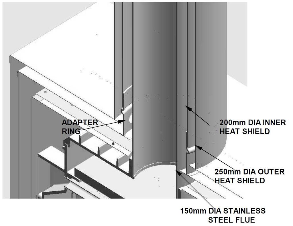
7 12. Cement tiles or slate to the top of the floor protector. The part inside the enclosure will not be visible and therefore does not need complete coverage. It is necessary to fix the finishing layer only under the support rails in this area. The visible edges of the floor protector are best finished with wooden trim or tiles. 13. Penetrate the roofing material on the flue centreline. Working from the bottom, assemble sections of the flue and the inner and outer flue heat shields (casings) and pass them up through the hole in the roof. The flue must be fixed at each joint with at least two rust-proof fasteners, and the crimped ends of the flue heat shields go to the top. When finally installed, the inner shield must extend up past the roof penetration point and the outer shield must be sufficiently high to avoid down-draughts in the finished flue. If the flue centreline is within 3m of the ridge, the outer shield must end at least 600mm above the roof ridge. If it is more than 3m from the ridge, the shield must extend at least 900mm above the point of roof penetration. If there are trees or high buildings in the vicinity, it may be necessary to increase this height to avoid down-draughts. Note that the 200mm adapter ring (with holes which ventilate the space between the flue and the inner shield) will be fitted into the shielding box assembly and will engage in the bottom of the inner heat shield (see Fig. 7). Fit a temporary support to hold the flue system high enough to permit sliding in the shielding box. 14. Assemble the base, sides, back and top panel of the shielding box (see Fig. 6). 15. Slide the assembly into place in the enclosure. After centralizing, fix the flange of the top panel of the shielding box through the cladding into the metal angle support, and fix the side flanges (through the cladding) into the wooden trimmers. 16. Pass the 200mm adapter ring (crimped end up) upwards into the hole in the top panel of the shielding box, and slide the top shield in under it so that the ring sits on top of the top shield and the top shield rests on the top edges of the inner heat shields of the cabinet. Make sure the back flange of the top shield hooks over the shield on the rear panel. Fix the top shield to the front flange of the top panel with 3 screws. 17. In New Zealand, building standards require that the appliance must have a seismic restraint to prevent shifting in the event of an earthquake. To provide seismic restraint, fix the shielding box to the floor (bearers in a elevated installation) with two 6mm masonry anchors (DYNABOLTS) or two 12 gauge screws. Use the two holes in the bottom of the shielding box. 18. Now go to the firebox cabinet and remove the two retaining screws and slide out the removable top section of the firebox cabinet. 19. Attach the tow centralizing brackets to the side panels of the firebox cabinet, flanges facing outwards. Use two screws provided for each bracket. 20. Remove the door: Open door and lift door until the top pivot disengages and then lower the door to free the bottom of the hinge. 21. Also remove top louver assembly by first lifting and then tilting in order to unhook from the cabinet. 22. Slide the firebox cabinet into the shielding box. Centralize it and secure the restraint brackets to the shielding box. 23. Complete the seismic restraint of the fire by screwing the base plate of the firebox to the bottom channels of the shielding box with two M6 screws. Use the two holes in the base. 24. Lower the assembled flue pipe (sections must be sealed and held together with three S/S fasteners) and seal and fix it to the flue socket of the heater. Lower the inner flue heat shield and engage its bottom end with the adapter ring. Lower the outer flue heat shield to sit on top of the shielding box. 25. Fit the two shield bracing angles at either ceiling or roof level as appropriate. Fix a suitable flashing where the outer shield penetrates the roof. 26. IMPORTANT. TO AVOID THE RISK OF A FIRE, COVER THE ENTIRE OPEN SPACE SURROUNDING THE HEAT SHIELD AT CEILING LEVEL WITH WIRE NETTING WHICH HAS A MESH SMALL ENOUGH TO PREVENT THE ENTRY OF BIRDS OR VERMIN INTO THE ENCLOSURE. 27. At the top of the flue, fix the flashing cone and fit the flue cowl in the usual way. There must be a 25mm gap between the top of the two casings and the flashing cone, so that the spaces between the flue pipe, inner and outer casings are properly vented. 28. Re-fit the removable top section of the firebox cabinet and secure it with two screws. 29. Fix the cladding to the enclosure side(s). 30. An un-shielded mantel-shelf may be fitted according to the height and width restrictions shown in Fig. 5. Shelves lower or wider than shown require a metal under-shield (see the installation manual). 7
8 31. Remove the standard top rail of the fascia and replace it by the vented one. Remove the bottom bar of the fascia and replace it by the vented bottom rail, taking care to trap the mains lead and grommet between the left end of the bottom rail and the left fascia upright. If necessary, replace the electrical connections at the rear of the fan switch (see installation manual) and ensure that the earth wire is connected to the post behind the Masport badge on the left fascia upright. 32. Connect the fan with help of a registered electrician as per instruction on page Fit the fascia by offering it up to the heater about 15 mm above its final position and lowering it, making sure the lip behind the top fascia rail engages in the slot at the top of the shielding box. Fit the six retaining screws. 34. Fit the upper and lower fascia grilles and the firebox door as described in the installation manual. 35. Ensure that the ceiling baffle, secondary air tube and the two side bricks and the two rear bricks are in the correct position. 36. Finish the floor protector by installing an edge trim if desired. NOTES FOR SPECIAL CONSTRUCTIONS & VARIATIONS : CONCRETE FLOORS: The above instructions assume that the heater is being assembled on a heat sensitive floor such as timber or particle board. Where the floor is not heat sensitive (e.g. concrete, the insulating floor protector may be omitted. However, if heat sensitive floor coverings are fitted it will be necessary to keep them at a safe distance. The most practical way to do this is to fix tiles to the floor where the floor protector would normally be. This will make the top of the protector approximately flush with the floor covering, so a larger floor protector will be needed. It must extend out to 453 mm from the face of the front cladding material, with a minimum width of 965 mm. Refer paragraph 6 and Fig 9. EXTERNAL INSTALLATIONS: In the case where the enclosure is to be erected outside the house, the shielding and flue installation details above will still apply. It is important to remember that the aperture in the wall of the house will need to be sufficiently high to permit the installation of heat resistant paneling in front of the heater to at least 1290 mm above the bottom of the shielding box rails. Suitable foundations will be required to support the weight of the enclosure and the heater and weatherproofing of the entire assembly will be necessary. BRICK FACED INTERNAL ENCLOSURES: Flue installation and clearance requirements are as detailed above. Brick wall construction will normally require a cast concrete base slab, so this slab could be extended to provide the necessary floor protection. CAUTION: If local Building Requirements permit laying the concrete slab on top of a wooden floor, it should be made of lightweight concrete and even then foundation support may be required. In any case, the slab should be poured on top of one layer of Micore 160 board (covered with sheet plastic to keep it dry) to prevent heat damage to the wooden floor. The top surface can be finished with bricks or tiles etc. In all cases the floor protector dimensions must be as previously shown. As before, the opening for the appliance in the front wall must be 737 nun wide and 719 mm high. Note that the bricks above the opening must extend to at least 1290 mm above the bottom of the shielding box rails. Fit the shielding box and complete the installation as previously detailed for standard installations. 8
9 Fig. 7 9
10 Fig. 8 INSTALLATION ON COMBUSTIBLE FLOOR WITH MANTLE SHELF Fig. 9 INSTALLATION ON CONCRETE FLOOR WITH MANTLE SHELF 10
11 Fig. 10 INSTALLATION - ELEVATED WITHOUT MANTLE SHELF Fig. 11 INSTALLATION ON COMBUSTIBLE FLOOR WITHOUT MANTLE 11
12 HEIGHTS OF FLUE PIPE & CASINGS FOR STANDARD CASING COVER & COWL & TOP FLUE PIPE SPAC- ER BRACKET BY GLEN DIMPLEX FALSE CHIMNEY VENTED THROUGH CASING COVER Fig. 12 HEIGHTS OF FLUE PIPE & CASINGS FOR STANDARD CASING COVER & COWL & TOP FLUE PIPE SPAC- ER BRACKET BY GLEN DIMPLEX FALSE CHIMNEY VENTED THROUGH SIDE VENT Fig. 13 NOTE: It is very important that the space between the flue pipe and the inner casing and the space between the inner casing and the outer casing are ventilated at the top. 12
13 HEARTH REQUIREMENTS: An insulating floor protector (hearth) is required. The minimum requirement for an insulating floor protector (hearth) is one layer of 6mm thick PROMATECT H, SUPALUX, or ETERPAN LD (or similar with a heat transition coefficient of 5 W/m³ K), and a layer of tiles or slate. This will give a thickness of approximately 14mm, and the extension from the face of the glass must be at least 441mm (or 440mm from fireplace surround) if the floor protector is flush with the surrounding heat sensitive material. The floor protector must be at least 875mm wide. It is desirable to carry the floor protector all the way inside the fireplace to ensure that the bottom of the zero clearance box does not rest below the top surface of the floor protector. The projection distance for the floor protector can be reduced if the height of the hearth is more than 0mm above combustible materials. Please refer to the following table: HEARTH HEIGHT ABOVE EXPOSED FLOOR PROJECTION FROM GLASS - P1 PROJECTION FROM FIRE PLACE SURROUND - P2 mm mm mm or greater
14 ELECTRICAL INSTALLATION ALL ELECTRICAL WORK MUST BE CARRIED OUT BY A LICENCED REGISTERED ELECTRICIAN. THE FAN IS TO BE PERMANENTLY CONNECTED TO THE MAINS SUPPLY WITH NO PERIPHERAL CONTROLS. THIS MEANS, THERE MUST NOT BE A PLUG AND SOCKET ARRANGEMENT. IN ORDER TO COMPLY WITH THE NEW ZEALAND ELECTRICAL STANDARDS, AN ISOLATION SWITCH IS NEEDED FOR ISOLATING THE FAN FROM THE SOURCE OF POWER. FOR FIRES INSTALLED IN THE CANTERBURRY REGION: A COMPLIANCE CERTIFICATE, SIGNED BY THE PERSON RESPONSIBLE FOR WIRING THE APPLIANCE, SHALL BE SUBMITTED TO THE CANTERBURY REGIONAL COUNCIL, WITHIN ONE MONTH OF INSTALLATION, TO CERTIFY THAT THE SYSTEM IS WIRED IN ACCORDANCE WITH THE MANUFACTURER S SPECIFICATIONS AND INSTRUCTION GIVEN IN THIS MANUAL. OPERATIONS OF FAN During the operation of the fire, once the fire has warmed up, the internally mounted heat operated switch (Thermodisc) will automatically switch the fan on. It may take approximately 15 minutes to reach the switching temperature. This is to prevent cold air being circulated. The fan will be running throughout the heating cycle. This is to ensure maximum efficiency for your woodfire. Once the fire has cooled down, the fan will automatically switch off. The fan uses very little power, approximately 30 Watts. SAFETY The appliance is not intended for use by young children or infirm person without supervision. Supervise young children to ensure they do not play with the appliance. If a supply cord is damaged, it must be replaced by the manufacturer, it s service agent or a suitably qualified person, in order to avoid electrical hazard. MAINTENANCE The fan should need little attention other than occasionally (perhaps once a year) removing it to clean dust and lint from the impeller. First using isolation switch, isolate the appliance from the electricity source. The fan can be accessed by removing the ash shelf. This is done by turning the two screws below the ash shelf 1/4 turn and pull the bottom of the shelf out and then lift the shelf up to disengage the top. Clean the impeller blades carefully by blowing or vacuuming. Do not apply force to the impellers. Reinstall the ash shelf. Switch ON the power supply using isolation switch. 14
15 SLIM AND WIDE FASCIA ASSEMBLY & INSTALLATION FOR LE4000 PROVINCIAL INSERTS If the fascia is not assembled use steps 1-4 to put together fascia components. Use steps 5 & 6 to attach fascia to firebox cabinet / casing. 1. Lay the fascia panels flat, face down on something soft so they won t scratch. 2. Align the bottom flange of each side panel with the corresponding end of the bottom rail. Using the self-tapping screws provided, attaché the bottom rail to the bottom flanges of the side panels. Tighten the screws only loosely at this stage. (see Fig.1) 3. Lower the top panel assembly into place with the locating prongs pointing down so that they fit inside the top edges of each side panel. Fasten the top panel to the case through the two holes in the lower flange of the top panel assembly. (see Fig.2) 4. Offer the fascia assembly up to the case to obtain the correct width for the side panel spacing keeping the inside flanges of each panel on the inner side of the mounting flange of the fireplace. Carefully remove the assembly and tighten the screws fastening the bottom rail to the side panels. 5. Ensure that the wires are away from the side of the fireplace. The power cord should be run behind the fascia panel and out through the slot in the side of the fascia. The rubber grommet on the power cord should be inserted into the slot to protect the power leads against possible damage. 6. Offer the fascia assembly up to the case once more and secure through the two holes on the inner edges of each fascia side panel and two holes of top panel assembly using the screws provided. (see fig.3) 15
WOOD FIRE INSTALLATION GUIDE
 WOOD FIRE INSTALLATION GUIDE WARNING: Improper installation, adjustment, alteration, service or maintenance can cause injury or property damage. For assistance or additional information consult an authorized
SI T T FST
 SI 440-600-700-700T-780-780T-900-1100 Freestanding TAPER TOP Open Fire - Wood Burner Installation Instructions Note: FLUE SYSTEMS Casing. Flue System may require to be Doubled Lined to Comply. Ref ASNZS:2918:2001
Nouveau BBQ Single Flue
 Nouveau BBQ 900-1100-1250-1500 Single Flue Outdoor BBQ Cooking Fire Wood Burner Installation Instructions FLUE SYSTEMS Casing. Flue system may require to be doubled lined to comply. Ref ASNZS:2918:2001
the heart of a warm home
 the heart of a warm home INSTALLATION HANDBOOK FOR THE FIRENZO INSERT RU FIRES RURAL WOODFIRE THIS FIRE CAN ONLY BE INSTALLED ON PROPERTIES OVER 2 HECTARES The Appliance and Flue System must be installed
170MM 360MM Specifications
 170MM 360MM 2016 Specifications EMISSION & EFFICIENCY The National Environmental Standards (NES) require a minimum 65% efficiency and maximum 1.5 grams emission requirement on all wood fires installed
Caution: FOR YOUR SAFETY
 Caution: FOR YOUR SAFETY This Decorative Open Gas Fire is designed and approved for insertion into an existing masonry fireplace and chimney, wall cavity or false chimney provided that the installation
KAZAN: MODEL SPECIFICATIONS 1. TECHNICAL DATA 2 2. PRE-INSTALLATION 3 3. INSTALLATION 6 4. OPERATION TESTING 11. Keep for future use
 KAZAN: MODEL SPECIFICATIONS 1. TECHNICAL DATA 2 2. PRE-INSTALLATION 3 3. INSTALLATION 6 4. OPERATION 10 5. TESTING 11 Keep for future use 1. TECHNICAL DATA WEIGHT AND DIMENSIONS: Dimensions Firebox W642
FIREPLACE INSERT ENCLOSURE INSTALLATION INSTRUCTIONS
 FIREPLACE INSERT ENCLOSURE INSTALLATION INSTRUCTIONS ENCLOSURE MODEL 90566400 FOR INSERT MODEL 5660NA And ENCLOSURE MODEL 90566000 FOR INSERT MODEL 5660 STANDARD KEEP THESE INSTRUCTIONS FOR FUTURE USE
MODEL. These instructions must be used in conjunction with the 'General Installation Instructions' for MASPORT wood fires.
 INSTALLATION SPECIFICATION SHEET These instructions must be used in conjunction with the 'General Installation Instructions' for MASPORT wood fires. CLEARANCE REQUIREMENTS This fire has been tested and
Installation instruction
 Installation instruction Ci51 www.contura.eu 114 CERTIFICATE Declaration of performance according to Regulation (EU) 305/2011 No. Ci51-CPR-150821-SE-2 PRODUCT Product type Type designation Manufacturing
These installation instructions cover the installation and operation of Jetmaster Inset and Freestanding Barbecues
 These installation instructions cover the installation and operation of Jetmaster Inset and Freestanding Barbecues ADDRESS Jetmaster Fires Ltd Unit 2, Peacock Trading Estate Goodwood Road Eastleigh Hampshire`
Gas Fireplaces. P36D-10 Gas Fireplace. Unit Dimensions With Vignette Faceplate. *** Important: Framing height requires consideration of the hearth
 28-15/16 (735mm) Model P36D-NG10 P36D-LP10 Fuel Type Natural Gas Propane Gas Fireplaces Minimum Supply Pressure Manifold Pressure - High Manifold Pressure - Low 5 W.C. (1.25 kpa) 3.8 W.C. (0.95 kpa) 1.1
INSTALLATION INSTRUCTIONS
 CHIMNEY CONNECTOR WALL THIMBLE MODEL IWT INSTALLATION INSTRUCTIONS Warnock Hersey C US LISTED ULC-S641/UL103 IT IS OF THE UTMOST IMPORTANCE THAT THIS WALL THIMBLE BE INSTALLED ONLY Y IN ACCORD CCORDANCE
Ecoteck Amalfi Freestanding. Wood Pellet Burning Heater
 coteck Amalfi reestanding Wood Pellet urning Heater c o t e c k A m a l fi r e e s t a n d i n g Wood Pellet urning Heater Installation Specifications Safety testing of the coteck Amalfi reestanding Wood
Absco Premier Garden Shed Assembly Instructions Model: 30302G
 Absco Premier Garden Shed Assembly Instructions Model: 3030G FRONT: 3.0m SIDE: 3.0m HEIGHT:.1m 3100mm CONCRETE SLAB 3100mm WHEN LAYING YOUR CONCRETE SLAB, CHAMFER THE 50mm EDGES DOWNWARDS BY 10mm. 50mm
Absco Premier Garden Shed Assembly Instructions Model: 30232G
 Absco Premier Garden Shed Assembly Instructions FRONT: 3.00m SIDE:.6m HEIGHT:.00m 360mm CONCRETE SLAB 3100mm CONCRETE WHEN LAYING YOUR CONCRETE SLAB, ENSURE THERE IS A REBATED EDGE 5mm DEEP AROUND THE
The Ashland Project. Total Area: 1,778 Sq.Ft. 3 Bedroom, 2 Bath, 2 Car Garage
 The Ashland Project Total Area: 1,778 Sq.Ft. 3 Bedroom, 2 Bath, 2 Car Garage The garage and bedroom extend from the front of this three bedroom home, drawing you visually into the entryway. Brick and stucco
BUILD A SHOWER CUBICLE
 BUILD A SHOWER CUBICLE Building a shower cubicle requires some experience in carpentry and tiling. You also need a degree of expertise in wiring and plumbing in order to install a shower unit. By all means
PATENTS ARE PENDING. Building Dimensions. Exterior Dimensions Roof Edge to Roof Edge
 Assembly Manual 8x9 PATENTS ARE PENDING Approximate Size 7640303 Storage Area Building Dimensions Exterior Dimensions Roof Edge to Roof Edge Interior Dimensions Wall to Wall Sq. Ft. Cu. Ft. Width Depth
Modular Coldroom Installation Manual
 Modular Coldroom Installation Manual May 2005 Disclaimer: The information contained in this installation guide is provided "as is". Bromic Pty Ltd does not warrant the accuracy, adequacy or completeness
SECTION (Master Template Final-05) ELECTRICAL BOXES. A. Provide boxes for electrical equipment and wiring devices as follows:
 ELECTRICAL BOXES. A. Provide boxes for electrical equipment and wiring devices as follows:") SECTION 16130 (Master Template Final-05) ELECTRICAL BOXES PART 1 GENERAL 1.01 SECTION INCLUDES A. Provide boxes for electrical equipment and wiring devices as follows: 1. Wall and ceiling outlet boxes.
SECTION 16130 (Master Template Final-05) ELECTRICAL BOXES PART 1 GENERAL 1.01 SECTION INCLUDES A. Provide boxes for electrical equipment and wiring devices as follows: 1. Wall and ceiling outlet boxes.
Planning and installation instructions
 Planning and installation instructions Stofix Oy Ahlmaninkatu 2 E 40100 Jyväskylä Finland stofixgroup@stofix.com www.stofix.com 2 PLANNING AND INSTALLATION INSTRUCTIONS... 1 1 General... 3 2 Project Design...
ROOF MOUNT KIT OWNERS MANUAL
 ROOF MOUNT KIT OWNERS MANUAL Made in the USA by: Primus Wind Power, Inc. 938 Quail St. Lakewood, CO 80215 Phone: (303) 242-5820 www.primuswindpower.com AIR is a trademark of Primus Wind Power, Inc. ROOF
Revision 1 RAM ELEVATORS. Elevator Electrical Planning Guide. RAM Manufacturing Ltd
 RAM ELEVATORS Elevator Electrical Planning Guide This guide is intended for people with an understanding of electricity. If you are not, please consult a licensed electrician as errors in application of
TC54. for architects & designers. Dimensions Clearances Venting
 for architects & designers TC54 Series D Dimensions Clearances enting IMPORTANT This booklet is intended as a basic specification guide for architects, designers and builders. Please refer to the Instruction
De Montfort Mark 7 Incinerator (Flatpack)
") De Montfort Mark 7 Incinerator (Flatpack) Introduction This design is specially for those occasions when a large number of incinerators are to be built at one location and transported to the places where
De Montfort Mark 7 Incinerator (Flatpack) Introduction This design is specially for those occasions when a large number of incinerators are to be built at one location and transported to the places where
DOUBLE SLIDE RAIL INSTALLATION METHOD. Double Slide Rail August
 Double Slide Rail August 2015 1 DOUBLE SLIDE RAIL INSTALLATION METHOD Introduction Slide rail shoring systems can be used for trenches up to 12m wide and 6m deep. Module length is determined by panels
Sorrento Stone Surrounds
 Sorrento Stone Surrounds For use with Riva 800, Riva 1050 & Studio 22 Installation and Maintenance Instructions For Use in Great Britain and Republic of Ireland (GB & IE) This product is suitable for use
FORM HEADWALL. FORM HEADWALL (floating) (floating) Installation Manual
 (floating) Installation Manual") FORM HEADWALL (floating) Installation Manual FORM HEADWALL (floating) OVERVIEW The Form is a UL-listed configurable headwall system. This system includes multiple horizontal equipment channels integrated
FORM HEADWALL (floating) Installation Manual FORM HEADWALL (floating) OVERVIEW The Form is a UL-listed configurable headwall system. This system includes multiple horizontal equipment channels integrated
Air flue duct for use with ecotec boilers
 For the installer Flue installation instructions Air flue duct for use with ecotec boilers Concentric System Ø 80/5 (Galvanized steel air duct/plastic flue duct) GB Contents Notes on the documentation
1. Start by removing the ash-pit door. Remove from frame by removing two rivet pins. Remove the frame by unscrewing the 4 bolts. (Fig 1.
 Page 1 INTRODUCTION This instruction shows how to replace ceramic bricks in the Solo Plus and Excel solid fuel boiler. Please read carefully before replacement. Follow the instruction point by point. Fig
Fireplace. Opening. Old. Opening up an old fireplace is like striking gold in your very own home.
 Opening up an Opening up an old fireplace is like striking gold in your very own home. In addition to a glowing, warmer, more welcoming living room, you are creating a much healthier and more invigorating
BISON PRECAST FLOORING SPECIFICATION
 BISON PRECAST FLOORING SPECIFICATION 1.0 SCOPE OF THE SPECIFICATION 1.01 Relates to: This specification covers the design, manufacture and associated site work of the following types of floors:- Hollowcore
DIVISION: SPECIALTIES SECTION: MANUFACTURED FIREPLACES REPORT HOLDER: EARTHCORE INDUSTRIES, LLC
 0 Most Widely Accepted and Trusted ICC ES Evaluation Report ICC ES 000 (800) 423 6587 (562) 699 0543 www.icc es.org ESR 2316 Reissued 10/2017 This report is subject to renewal 10/2018. DIVISION: 10 00
SECTION IMPACT RESISTANT WALL PROTECTION
 SECTION 10265 PART I - GENERAL 1.01 DESCRIPTION A. Scope: Work under this Section shall include all materials and installation necessary to provide Impact-Resistant Wall Protection including Wall guards,
OmniFlex 300 Plus Installation Instructions
 OmniFlex 300 Plus Installation Instructions IMPORTANT PortaFab advises a thorough reading of these instructions before beginning installation. INTRODUCTION Instructions should be read thoroughly and cross-referenced
Davis Frame Co., Inc. Construction Budget Considerations
 Davis Frame Co., Inc. Construction Budget Considerations ITEM BID 1 BID 2 BID 3 MISCELLANEOUS COSTS Surveying Building Permit Engineering Fees Interest on Construction Loan Property Taxes Hazard & Liability
SUMMARY. Appliance: Corrective Action(s)
") Appliances: Range/Oven/Cooktop Appliance: Corrective Action(s) Finding # 1 **Range anti-tip bracket is not installed. Anti-tip brackets are safety devices installed to prevent the range from tipping forward.
Appliances: Range/Oven/Cooktop Appliance: Corrective Action(s) Finding # 1 **Range anti-tip bracket is not installed. Anti-tip brackets are safety devices installed to prevent the range from tipping forward.
ZS880 Linear Shower Drain Installation Instructions
 Introduction PATENT PENDING The Zurn ZS880 Stainless Steel Linear Shower Drain incorporates a simple approach to bathroom shower design, when compared to traditional point-drain applications. The linear
BASEMENT FINISH PERMIT AND BUILDING CODE REQUIREMENTS (REVISED 3/6/2018)
") BASEMENT FINISH PERMIT AND BUILDING CODE REQUIREMENTS (REVISED 3/6/2018) PERMIT SUBMITTAL CHECKLIST: Signed and completed Building Permit application form. A separate Electrical permit is required from
BASEMENT FINISH PERMIT AND BUILDING CODE REQUIREMENTS (REVISED 3/6/2018) PERMIT SUBMITTAL CHECKLIST: Signed and completed Building Permit application form. A separate Electrical permit is required from
SECTION I -- IRONWORK
 SECTION I -- IRONWORK CONTENTS PAGE 1. GENERAL... I-2 1.1. Introduction... I-2 2. REQUIREMENTS... I-2 2.1. General... I-2 2.2. Auxiliary Framing... I-2 2.3. High Seismic Risk Zone Requirements... I-3 2.4.
Smarter. Safer. Leaner.
 Smarter. Safer. Leaner. Fast Installation and Removal Decrease Leading Edge Exposure by 87% OSHA Compliant Versatile and Reusable Use Perimeter Protection Posts During Construction: At Building Perimeter
A. ASTM C190 - Test Method for Tensile Strength of Hydraulic Cement Mortars
 SECTION 04850 (04 40 00) MSI PRECAST STONE VENEER SYSTEM PART 1 GENERAL 1.1 SECTION INCLUDES A. MSI Precast Stone Veneer for exterior and interior vertical surfaces. 1.2 RELATED SECTIONS Specifier Notes:
Vertigo Cladding Board
 Installation guide Vertigo Cladding Board Geolam: a stunning alternative to wood cladding Vertigo is a composite wood cladding board requiring minimum maintenance. Durable and fade resistant, it will not
Executive Summary. Service can be provided for 5x8 at standard rates, or 7x24 at premium rates. Available for most Wright Line Products
 Seismic Bracing Contents Executive Summary...1 Details of Service for Concrete Slab Floor...2 Details of Service for Raised Tile Computer Room Floor..3 Assumptions...4 Scope of Responsibility...5 Other
This Installation Guide uses the following symbols to indicate important information. Always observe the instructions indicated by these symbols.
 VIGO INDUSTRIES INSTALLATION GUIDE FOR STANDING SHOWER CABIN (MODEL VG06062) SAFETY PRECAUTIONS This Installation Guide uses the following symbols to indicate important information. Always observe the
MODULAR ACOUSTIC FENCING INSTALLATION GUIDE
 MODULAR ACOUSTIC FENCING WWW.QUICKBUILTSYSTEMS.COM.AU INSTALLATION GUIDE INTRODUCTION THE QUICKBUILT FENCE SYSTEM IS A SMARTLY DESIGNED MODULAR SYSTEM EASY AND FAST TO INSTALL AND COST EFFECTIVE. // THE
Roof. Installation Instructions PINK BATTS CEILING INSULATION. Safety: pinkbatts.co.nz INSTALLATION INSTRUCTIONS
 Roof PINK BATTS CEILING INSULATION Installation Instructions Correct installation with no compression, gaps or folds is critical to ensure Pink Batts ceiling insulation performance is not compromised.
TECHNICAL GUIDANCE XXXX 2015 EXXON QUESTION ANSWER. page 1 of 9
 MARKINGWALLING OF SAFETY GLASS SPANDREL CURTAIN PANELS FORMED TO COLDFROM ROOFS STACKED WINDOW 7.2 /25 January ARRANGEMENTS (First Issue) XXXX EXXON QUESTION Which factors should be taken into account
Free 17'x6' Chicken Run Plan. Designed for up to 11 chickens
 Free 17'x6' Chicken Run Plan Designed for up to 11 chickens Disclaimer The information provided here will show you how to build a chicken coop. However, we at howtoplans.org do not claim that the recommended
RECONSTRUCTION AND REPLACEMENT OF EARTHQUAKE DAMAGED MASONRY CHIMNEYS
 INFORMATION BULLETIN / PUBLIC BUILDING CODE REFERENCE NO.: LABC 2113 and LARC R1001 DOCUMENT NO.: P/BC 2014-070 Previously Issued As: P/BC 2008-070 Effective: 01-01-2014 Revised: 01-16-2014 RECONSTRUCTION
Low-profile, 11U high cabinets hold networking equipment, servers, and phone equipment.
 RM140A-R3 RM140A-M-R3 RM145A-R3 RM145A-M-R3 Small Office/Home Office (SOHO) Cabinets Low-profile, 11U high cabinets hold networking equipment, servers, and phone equipment. Fit under most desktops in the
SECTION RADIATION SHIELDING ENCLOSURE Low Intensity Radiation Protection
 SECTION 13090 RADIATION SHIELDING ENCLOSURE Low Intensity Radiation Protection Prepared by: 90 Dayton Avenue, Unit 4B, Suite 13 Passaic, NJ 07055 (973) 574-9077 13090-1 LOW INTENSITY RADIATION PROTECTION
Wood Burning Fireplace
 Wood Burning Fireplace OWNER S OPERATION AND INSTALLATION MANUAL ICC-ES #ESR-2542 (V)GM36, (V)GM42 AND (V)GM50 Series and WCM-36G, WCM-42G and WCM-50G Wood Burning Masonry Fireplaces with Insulation SAVE
Installation instructions
 Installation instructions Holetherm Double-walled flue gas discharge system (DW) 2016 All information in this release is subject to misprints. No liability is accepted for the consequences of misprints.
1. Hangers and supports for electrical equipment and systems. 2. Construction requirements for concrete bases.
 SECTION 260529 - HANGERS AND SUPPORTS PART 1 - GENERAL 1.1 SUMMARY A. Section includes: 1. Hangers and supports for electrical equipment and systems. 2. Construction requirements for concrete bases. 1.2
INSTALLATION GUIDE Tranquil Mount Model: TMO400A
 ISTALLATIO GUIDE Tranquil Mount Model: TMO00A Support 32" to 50" Screens Load Capacity: 13.2~65 lbs (6~30 kg) VESA And on-vesa compatible 100mm x 100mm 200mm x 100mm 300mm x 100mm 00mm x 100mm 200mm x
RESIDENTIAL NEW CONSTRUCTION PLAN REVIEW CHECKLIST
 This list is provided as a guide to help you understand the information that must be contained on the construction drawings. This list is not all-inclusive of all building codes but is used as a general
Division 11 - Equipment Section 11401
 PART 1 - GENERAL 1.1 GENERAL A. Division 1 General Requirements applies and becomes a part of this Section of the Specification as fully as if repeated herein. B. Items of equipment which are included
Project s fiche INOV. Frisomat Case study project's fiche INOV
 Project s fiche INOV Clear Flatro building 49 metres long The Flatro industrial building in Villers-le-Bouillet measures 15 metres by 49 metres and is 6 metres high. The building rests on concrete plinths
B. Polyethylene samples shall be submitted for Owner approval of color and quality.
 Glass Rail ENGINEERED DASHERBOARD SPECIFICATIONS PART 1 - GENERAL 1.01 PROJECT SCOPE A. Contractor shall furnish and install one complete set of steel framed dasherboards as indicated on the drawings and
insert fires dimensions and specifications properties under 2 hectares (ag), properties over 2 hectares (ru) athena aqualux ag or ru
, properties over 2 hectares (ru) athena aqualux ag or ru") insert fires dimensions and specifications properties under 2 hectares (ag), properties over 2 hectares (ru) athena aqualux ag or ru forte aqualux ag or ru 705 F R F R athena bay ag or ru forte bay ag
insert fires dimensions and specifications properties under 2 hectares (ag), properties over 2 hectares (ru) athena aqualux ag or ru forte aqualux ag or ru 705 F R F R athena bay ag or ru forte bay ag
h Installation Manual
 h Installation Manual 1 General Information The installation of HOBAS GRP Pipes is subject to applicable standards and guidelines such as EN 1610 and ISO/ TS 10465-1. Correct installation always requires
SpaVault TM Installation Guide for Bullfrog Spas (7-10 x 7-10 x 38 )
") SpaVault TM Installation Guide for Bullfrog Spas (7-10 x 7-10 x 38 ) WARNING - When unpacking SpaVault, DO NOT discard styrofoam pieces, these are not packaging materials. Step 1 Excavation Important:
SpaVault TM Installation Guide for Bullfrog Spas (7-10 x 7-10 x 38 ) WARNING - When unpacking SpaVault, DO NOT discard styrofoam pieces, these are not packaging materials. Step 1 Excavation Important:
University Apartments on Brooklyn PROJECT MANUAL
 Section 122100 Horizontal Louver Blinds University Apartments on Brooklyn PART 1 - GENERAL 1.1 SECTION INCLUDES A. Horizontal slat louver blinds. B. Operating hardware. 1.2 RELATED SECTIONS A. Section
Steel Floor Framing Solutions
 Steel Floor Framing Solutions Complete packages for domestic floors, decks and additions Product Manual & General Information Individually designed solutions Full design and quote service Drawings and
HYBRID. Pre-Laying Checks
 Warning Veles CK has been developed for exceptional stability in low and high temperatures, however, after installation extreme temperatures (under 5 C or over 50 C) should be avoided by use of interior
H 12 Heavy Duty Modern Tripod 8 Seat Swing Heavy Duty Hangers
 Page 1 IMPORTANT Please retain this instruction sheet in your files. It contains important replacement parts information. All equipment should be installed in accordance with these instructions. It is
SECTION ACOUSTICAL PANEL CEILINGS
 SECTION 095113 ACOUSTICAL PANEL CEILINGS PART 1 - GENERAL 1.1 RELATED DOCUMENTS A. Drawings and General Provisions of the Contract, including General and Supplementary Conditions and Division 01 Specification
STEP UP SHOWER BASE INSTALLATION GUIDE FOR TIMBER AND CONCRETE FLOORS
 GUIDE FOR TIMBER AND CONCRETE FLOORS EDITION: APRIL 2016 IMPORTANT: This guide is for the installation of a Step Up shower base on a timber or concrete floor. If you require a walk in (flush with floor)
Se incluyen las instrucciones en español
 Page 1 of 16 Pittsburgh Corning Corporation Pittsburgh, PA 15239 1-800-624-2120 www.pittsburghcorning.com All trademarks and registered trademarks in this brochure are owned and protected by Pittsburgh
SECTION SECTIONAL OVERHEAD DOORS 522 SERIES ALUMINUM SECTIONAL OVERHEAD DOORS. Display hidden notes to specifier. (Don't know how?
 SECTION 08360 SECTIONAL OVERHEAD DOORS 522 SERIES ALUMINUM SECTIONAL OVERHEAD DOORS Display hidden notes to specifier. (Don't know how? Click Here) PART 1 GENERAL 1.1 SECTION INCLUDES A. Glazed Aluminum
Optima Vector Plank. Installation Instructions. Ceiling
 Ceiling Systems Between us, ideas become reality Optima Vector Plank Installation Instructions 1. GENERAL 1.1. Product Description The Vector products referenced in these instructions are made from fiberglass.
SECTION HANGERS AND SUPPORTS FOR ELECTRICAL SYSTEMS
 SECTION 26 05 29 HANGERS AND SUPPORTS FOR ELECTRICAL SYSTEMS PART 1 GENERAL 1.1 DESCRIPTION A. Scope: 1. CONTRACTOR shall provide all labor, materials, equipment, and incidentals as shown, specified, and
GIB Quiet Clip GIB CBI March Features and Benefits
 CBI - 5113 March 2002 GIB Quiet Clip Features and Benefits No special flooring systems required Easy fit Installation Significantly improves low frequency sound transmission Significantly improves low
HOW TO: INSULATE YOUR HOME AND UNDERSTAND U-VALUES GTEC THERMAL BOARD WITH PLASTERBOARD
 HOW TO: INSULATE YOUR HOME AND UNDERSTAND U-VALUES WITH PLASTERBOARD GTEC THERMAL BOARD 1 BUILDING INSULATION THE REGULATIONS Building regulations are in place to drive improvements in thermal efficiency,
How to choose the best furnace?
 How to choose the best furnace? We assume that the house has an average insulation, quality windows and doors and 8 foot ceilings, with a location in an area where winter temperatures are comparable to
Canopies & Exposed Structure Areas Commercial Ceilings and Walls Solutions Guide
 CEILING & WALL SYSTEMS Canopies & Exposed Structure Areas Commercial Ceilings and Walls Solutions Guide Canopies & Exposed Structures SOUNDSCAPES Acoustical Canopies Product Description SoundScapes are
Xtratherm Thin-R Partial Fill Cavity Wall Board (XT/CW Grade)
") CERTIFICATE NO. 03/0183 DETAIL SHEET 1 Xtratherm Thin-R Partial Fill Cavity Wall Board (XT/CW Grade) PRODUCT DESCRIPTION This Detail Sheet relates to Xtratherm Thin-R Partial Fill Cavity Wall Board, as
CERTIFICATE NO. 03/0183 DETAIL SHEET 1 Xtratherm Thin-R Partial Fill Cavity Wall Board (XT/CW Grade) PRODUCT DESCRIPTION This Detail Sheet relates to Xtratherm Thin-R Partial Fill Cavity Wall Board, as
SECTION BASIC ELECTRICAL MATERIALS AND METHODS
 SECTION 26 05 05 BASIC ELECTRICAL MATERIALS PART 1 - GENERAL 1.1 SUMMARY A. Section includes the limited scope construction materials and methods for application with electrical installations as follows:
PV Mounting System 2703 SERIES 200 UL GROUND MOUNT SYSTEM. SnapNrack Residential PV Mounting Systems Code Compliant Installation Manual
 PV Mounting System 2703 SERIES 200 UL GROUND MOUNT SYSTEM SnapNrack Residential PV Mounting Systems Code Compliant Installation Manual Series 200 UL Introduction Series 200 UL Introduction SnapNrack Series
CANTILEVER RACK SPECIFICATIONS PART 1 GENERAL 1.1 SCOPE 1.2 APPROVED MANUFACTURER 1.3 REGULATORY ORGANIZATIONS AND GROUPS 1.4 QUALITY ASSURANCE
 CANTILEVER RACK SPECIFICATIONS PART 1 GENERAL 1.1 SCOPE This specification is intended to describe the general requirements applicable to a proper structural cantilever rack design. In addition, it is
This Listed Top Vented Gas Log Enclosure is designed for use with Decorative Natural Gas or Propane (LP) Gas Appliances, only.
 Gas Appliances, only.") ISOKERN B-VENT FIREPLACE A PRODUCT OF EARTHCORE INDUSTRIES, LLC. INSTALLATION, OPERATION, MAINTENANCE and OWNER S MANUAL ISOKERN MODELS IBV-36 and IBV-46 IMPORTANT: This manual contains assembly rules,
ISOKERN B-VENT FIREPLACE A PRODUCT OF EARTHCORE INDUSTRIES, LLC. INSTALLATION, OPERATION, MAINTENANCE and OWNER S MANUAL ISOKERN MODELS IBV-36 and IBV-46 IMPORTANT: This manual contains assembly rules,
GRAND MERIDIAN WOOD BURNING / VENT-FREE GAS FIREPLACES INDOOR / OUTDOOR TRULY TIMELESS. Traditional. Fireplace Design Collection
 GRAND MERIDIAN WOOD BURNING / VENT-FREE GAS FIREPLACES INDOOR / OUTDOOR Traditional Fireplace Design Collection TRULY TIMELESS 4 SHOW YOURSELF Create a room that begs you to stick around, sit down and
Modular Masonry Fireplace Installation Instructions Models TFS/OFS* 33 /39 /44 /49 /63
 WWW.BURNTECH.COM Modular Masonry Fireplace Installation Instructions Models TFS/OFS* 33 /39 /44 /49 /63 THIS ENTIRE INSTALLATION GUIDE IS TO BE FOLLOWED IN ITS ENTIRETY FOR INDOOR TRADITIONAL FIREPLACE
10 Steps to Save Energy in Your House
 10 Steps to Save Energy in Your House Sealing and insulating your home is one of the most cost-effective ways to make your home more comfortable and energy efficient. You can do it yourself. In this chapter,
Backer Box INSTALLATION
 Backer Box INSTALLATION & BUILDING GUIDE 10.625" 17.5" Green Glue Cement Board Light Fixture 7/16 OSB 1 Building a Backer Box We all love the look of the light from an array of recessed ceiling cans. Be
mounting systems applications overview
 mounting systems applications overview catalogue version January 2015 tritec mounting systems: overview of applications i. pitched roof: roof-top 1. Tiles, shingles and corrugated panels 1.1 TRI-STAND
GUIDELINES FOR SANITARY DESIGN AND CONSTRUCTION OF MILK PRODUCTS PLANTS (rev )
") Milk and Dairy Food Safety Branch 1220 N Street, Sacramento, CA 95814 GUIDELINES FOR SANITARY DESIGN AND CONSTRUCTION OF MILK PRODUCTS PLANTS (rev. 10-20-2011) The outline below lists sanitary requirements
Milk and Dairy Food Safety Branch 1220 N Street, Sacramento, CA 95814 GUIDELINES FOR SANITARY DESIGN AND CONSTRUCTION OF MILK PRODUCTS PLANTS (rev. 10-20-2011) The outline below lists sanitary requirements
1. Cast-in-place concrete is specified in Section
 SECTION 03 38 00 PART 1 - GENERAL 1.01 DESCRIPTION A. This Section describes the requirements for furnishing and installing post-tensioned slabs, jacks, jacking and anchors at Parking Structure, and record
CITY OF CEDAR FALLS DEPARTMENT OF DEVELOPMENTAL SERVICES INSPECTION SERVICES DIVISION PHONE Residential Accessory Structures
 CITY OF CEDAR FALLS DEPARTMENT OF DEVELOPMENTAL SERVICES INSPECTION SERVICES DIVISION PHONE - 268-5161 Residential Accessory Structures This information has been compiled for the benefit of any person
A. This Section includes acoustical panel ceilings installed with exposed suspension systems.
 SECTION 09511 ACOUSTICAL PANEL CEILINGS PART 1 - GENERAL 1.01 RELATED DOCUMENTS A. Drawings and general provisions of Contract, including General and Supplementary Conditions and Division 1 Specification
HORSE SHELTERS 6, 12, 15, 18, & 24 SHELTERS ASSEMBLY MANUAL
 HORSE SHELTERS 6, 12, 15, 18, & 24 SHELTERS ASSEMBLY MANUAL Read this manual before using product. Failure to follow instructions and safety precautions can result in serious injury, death, or property
Typical Finished Basement Details
 Albemarle County, Virginia Typical Finished Basement Details Based on the 2012 Virginia Residential Code Finished basements must be constructed in conformance with these details. For requirements, details
TECHNICAL INFORMATION SHEET NUMBER 1a
 BASIC BUILDING REQUIREMENTS FOR THE CONSTRUCTION OF TRADITIONAL SQUASH COURTS Building Requirements The dimensions of a singles or doubles court is shown on the attached diagram. Width and length of the
One and Two Family Additions
 One and Two Family Additions An addition to a house, duplex, garage, or an accessory structure requires a building permit prior to performing any construction. Building Department & Permit Office Mon-Fri
STANDARD PLAN BULLETIN SP-2 (Structural)
") STANDARD PLAN BULLETIN SP-2 (Structural) Date: January 20, 2000 This Los Angeles Department of Building and Safety (LADBS) standard plan provides prescriptive details to facilitate the reconstruction of
STANDARD PLAN BULLETIN SP-2 (Structural) Date: January 20, 2000 This Los Angeles Department of Building and Safety (LADBS) standard plan provides prescriptive details to facilitate the reconstruction of
Building Regulations
 Product 1.1 Technobond is a range of polyester fibre insulation used as thermal and acoustic insulating material in ceilings, roofs and walls of buildings. Appraisal No.69 [010] BRANZ Appraisals Technical
High Piled Combustible Storage Guideline
 Moreno Valley High Piled Combustible Storage Approved and Authorized By: Adria Reinertson, Fire Marshal Issued: May 5, 2017 Rev: 7-28-16 City of Moreno Valley Fire Department Page 1 of 19 High Piled Storage
Fielders Steel Door Frames. Architectural and Commercial
 Fielders Steel Door Frames The Fielders Steel Door Frame is a strong and durable solution, made from 100% Australian steel by BlueScope. We offer an extensive range of standard sizes and a complete custom