PUBLIC STORM DRAIN STANDARDS
|
|
|
- Colin McCarthy
- 6 years ago
- Views:
Transcription
1 CITY OF SANTA ROSA PUBLIC STORM DRAIN STANDARDS Adopted by the Santa Rosa City Council Resolution No Date: 4/26/2005 EXHIBIT A
2 TABLE OF CONTENTS 1. Public Storm Drain Design Standards 2. Public Storm Drain Standard Drawings 3. Public Storm Drain Construction Standard Specifications 4. Engineer's List of Approved Items APPENDIX A STORM DRAIN DESIGN REVIEW SUBMITTAL CHECKLIST
3 PUBLIC STORM DRAIN STANDARDS
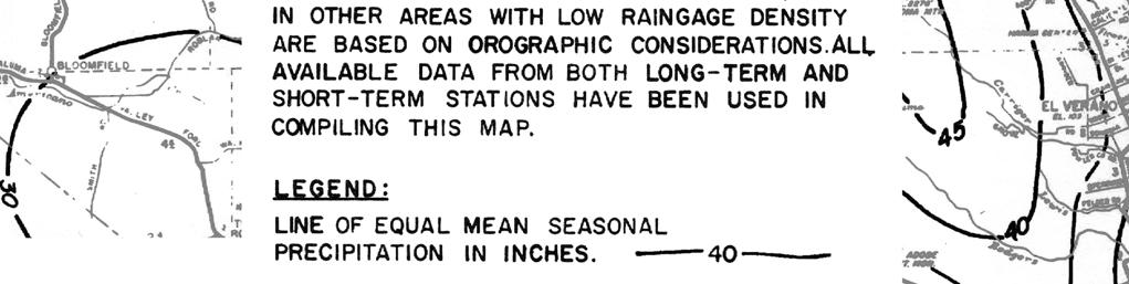
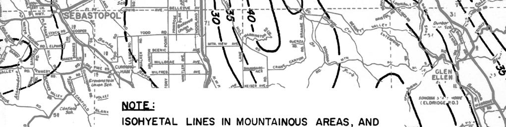
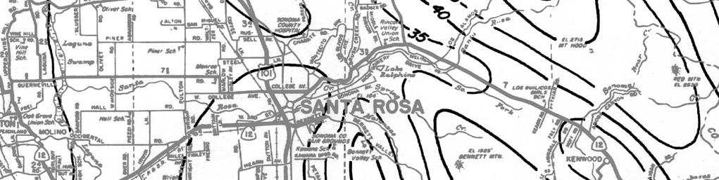
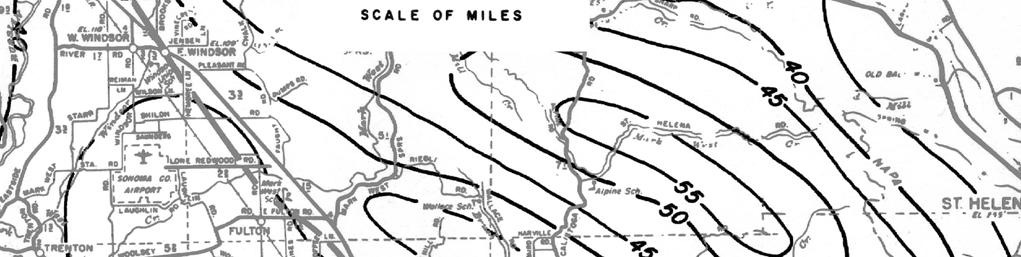
4 1. PUBLIC STORM DRAIN DESIGN STANDARDS PREFACE QUICK REFERENCE SHEET HYDROLOGY QUICK REFERENCE SHEET HYDRAULICS QUICK REFERENCE SHEET DESIGN REQUIREMENTS Purpose...1 Policy...1 Hydrology Concepts...1 Runoff Coefficient...2 Rainfall Intensity...2 Time of Concentration...2 Hydrologic Design...3 Hydraulic Design Criteria...4 General...4 Open Channels...6 Closed Conduits...7 Detention Basins...7 Design Requirements Connection to the Existing Storm Drain System Materials Size Alignment Slope Cover Manholes and Structures Catch Basins Easements Access Road Maintenance Water Quality Other Requirements...14 Table I-1 Rational Method Runoff Coefficients (C)...15 Figure I-1 Intensity-Duration-Frequency Graph...16 Figure I-2 Mean Seasonal Precipitation...17 Table I-2 Formulas...18 Table I-3 Loads on Buried Pipes...19
5 PREFACE Quick Reference Sheets These standards have been prepared to assist developers and their engineers in the design of public storm drain facilities. To assist those engineers who are familiar with these standards, quick reference sheets are provided in this Preface section. The quick reference sheets contain design criteria and data from the standards which are most commonly used in the design of public storm drain facilities. Unless otherwise noted, hydrological and hydraulic standards are consistent with the Sonoma County Water Agency Flood Control Design Criteria Manual, Revised August Quick reference sheets are provided for the following subjects: 1. Hydrology 2. Hydraulics 3. Design Requirements
6 Q = CIAK where: Waterway classification QUICK REFERENCE SHEET HYDROLOGY Drainage area, square miles Recurrence interval, years Major $4 100 Secondary Minor #1 10 Diversion Not applicable 100 Q = flow (cubic feet per second) C = runoff coefficient from Table I-1 (dimensionless) I = rainfall intensity from Figure I-1 (inches per hour) A = drainage area (acres) K = mean seasonal precipitation from Figure I-2 30 inches Initial Time of Concentration (Tc) Land use Tc Commercial/industrial/residential with more than 8 units per acre Residential, 2 to 8 units per acre Residential, less than 2 units per acre Open Space 7 minutes 10 minutes 15 minutes 15 minutes Rational Method Runoff Coefficients (C) 15 Intensity-Duration-Frequency Chart 16 Mean Seasonal Precipitation Map 17 Page
7 Design waterway classification QUICK REFERENCE SHEET HYDRAULICS Downstream waterway classification Design flow in downstream waterway, years Secondary Major 25 Minor Major or secondary 10 Surface (ground) Major or secondary 100 Diversion Not applicable 100 Manning's formula Q = (1.486/n)AR 2/3 S 1/2 Manning's formula coefficient (n) Material Storm drain pipe [high density polyethylene pipe (HDPE), cast-in-place concrete (CIPP), and reinforced concrete pipe (RCP)] Concrete-lined channel Asphaltic concrete Grouted rock rip rap Loose rock rip rap Grass-lined channel Constructed natural waterway Mannings "n" minimum minimum Minimum design flow velocity = 2.5 feet per second Waterway classification Waterway type Minimum freeboard All Open channel 1.5 feet or 20 percent of specific energy (whichever is greater) Major and secondary Closed conduit 0.2 x diameter Minor Closed conduit 1 foot below top of curb or adjacent ground surface Gutter Open channel with 6-inch curb 0.4 feet maximum depth
8 QUICK REFERENCE SHEET DESIGN REQUIREMENTS Minimum pipe diameter: Pipe materials: Horizontal separation from sewer lines: Horizontal separation from water lines and other utilities: Vertical curves: Horizontal curves: 15 inches reinforced concrete pipe (RCP), cast-in-place concrete pipe (CIPP) or high-density polyethylene (HDPE) pipe that conforms to these specifications 5 feet clear 4 feet clear not allowed RCP and CIPP: 300 feet minimum radius (allowed at catch basins and when pipeline is installed under the pavement parallel to the concrete gutter) Pipe slope: #15% HDPE: 765 feet minimum radius for 20 foot sections Minimum cover: 12 inches for class III RCP and HDPE (outside of pipe to road subgrade). Maximum distance between structures: 400 feet New development and redevelopment projects may be required to implement storm water quality source and treatment controls. Refer to the Santa Rosa Area Standard Urban Storm Water Mitigation Plan (SUSMP) for design criteria.
9 PUBLIC STORM DRAIN DESIGN STANDARDS PURPOSE: The purpose of this document is to provide standards for design of public storm drain system improvements in the City of Santa Rosa (City). These standards consist of: (1) hydrologic design criteria, (2) hydraulic design criteria, and (3) physical design requirements. These standards do not include (but may reference) additional requirements established by other departments of the City and other government agencies. These standards are intended to impose minimum acceptable design criteria. More stringent requirements may be imposed by the City Engineer based on specific project conditions. Developers and their design engineers are responsible for complying with these standards and all other requirements for design of storm drain facilities within the City. Design engineers are responsible for initiating written requests for approval of any design concepts that differ from these standards, verifying additional requirements set forth by other departments of the City or other government agencies, performing any necessary calculations or studies, and resolving any problems with the appropriate department or agency. Developers and design engineers should be aware that Section 402(p) of the federal Clean Water Act establishes requirements for National Pollutant Discharge Elimination System permits for certain industrial and construction-related storm water discharges. POLICY: The policy of the City is to safely collect and convey storm water to the nearest public flood control facility in a storm drain system approved by the City of Santa Rosa Public Works Department (PWD), while achieving water quality objectives to the maximum extent practicable in the City's creeks as defined in the City s Storm Water Management Plan. HYDROLOGY CONCEPTS: The Rational Method is widely used for determining design flows in urban and small watersheds. The method assumes that the maximum rate of runoff for a given rainfall intensity occurs when the duration of the storm is such that all parts of the watershed are contributing to the runoff at the interception point. The formula used is an empirical equation that relates the quantity of runoff from a given area to the total rainfall falling at a uniform rate on the same area and is expressed as: in which Q = CIAK Q is the design flow in cubic feet per second. C is a dimensionless runoff coefficient based upon type of ultimate development (i.e., land use) from Table I-1 for the drainage area. I is the intensity of rainfall in inches per hour from Figure I-1 or computed as: -1-
10 I = 5.12 Y t in which Y = recurrence interval (10, 25 or 100 year, etc.) t = time of concentration (duration in minutes) A is the tributary drainage area in acres. K is the dimensionless ratio of the average annual rainfall for the drainage area to the average annual rainfall for the overall area for which the rainfall intensity/duration/recurrence interval relationships have been established. K = average annual rainfall in inches from Figure I-2 30 inches The runoff coefficient (C), the drainage area (A), and the average annual rainfall ratio (K) are all constant for a given area at a given time. (Note that some agencies do not include the factor K when using the Rational Method.) Rainfall intensity (I), however, is determined by using an appropriate storm frequency (i.e., recurrence interval) and duration which are selected on the basis of economics and engineering judgment. Storm drains are designed on the basis that they will flow nearly full during the design storms. Storm frequency is selected through consideration of the size of drainage area, probable flooding, possible flood damage, and anticipated future development for the drainage area. Runoff Coefficient. The runoff coefficient (C) normally ranges between 0.30 and The soil characteristics, such as porosity, permeability, and whether or not it is saturated from preceding storms are important considerations. Another factor to consider is ground cover, i.e., whether the area is paved, grassy or wooded. In certain areas, the coefficient depends upon the slope of the terrain. Duration of rainfall and shape of area are also important factors in special instances. Of primary importance is the percent of land covered with impervious surfaces such as asphalt. Rainfall Intensity. Rainfall intensity (I) is the amount of rainfall measured in inches per hour that would be expected to occur during a storm of a certain duration. The storm frequency is the time in years in which a certain storm would be expected again and is determined statistically from available rainfall data. ( See Figure I-1.) Time of Concentration. The time of concentration at any point in a storm drain segment is the time required for runoff from the most hydraulically remote portion of the drainage area to reach that point. The most hydraulically remote portion provides the longest time of concentration but is not necessarily the most distant point in the drainage area. Since a basic assumption of the Rational Method is that all portions of the area are contributing runoff, the time of concentration is used as the storm duration in calculating the intensity. The time of concentration consists of the initial time of concentration, which depends on the anticipated future land use for the drainage area, plus the sum of the additional overland flow time, if any, and the times of travel in street gutters, roadside swales, storm drains, drainage channels, and other drainageways. The time of concentration is affected by the rainfall intensity, topography, and ground conditions. -2-
11 HYDROLOGIC DESIGN: Hydrologic design shall be based on the ultimate development and slope of the tributary watershed. All storm drain facilities shall be designed for flows resulting from 100 percent build-out of the land uses designated in the latest adopted edition of the City's General Plan in effect at the time the proposed development is approved by the appropriate City approval body. Drainage boundaries and basin slope shall be determined from the most current topographic information available. In flat areas, drainage basin boundaries shall be verified with those for other adjacent developments to eliminate gaps or overlaps and maintain consistency. Only areas which do not flow towards the proposed development may be excluded. The design must demonstrate that the excluded areas do not flow into the proposed development. Flows from tributary areas upstream of the proposed development shall be included in the hydrologic design for the proposed development. The hydrology for the proposed project will be based on a pattern of upstream development which delivers the ultimate development storm runoff to the proposed project. Upstream area flows shall be based on 100 percent build-out of the land uses designated in the latest adopted edition of the City's General Plan in effect at the time the project is designed. Rezoning often results in significantly higher densities than were used in design calculations for existing downstream storm drain facilities. The design of the storm drain system for the proposed development shall be based on the assumption that storm flows from upstream areas will be conveyed in conduits, thereby resulting in lower times of concentration than for undeveloped conditions. The design of the storm drain facilities for the proposed development shall be such that the design flow from the proposed development and the upstream areas is less than or equal to the hydraulic capacity of the downstream storm drain facilities unless otherwise approved. In cases where the design flow exceeds the hydraulic capacity of the downstream storm drain facilities, improvements to the downstream facilities may be required as part of the development. Developed public areas, including but not limited to public parks and golf courses, may be considered to be vegetated to the extent that they are actually vegetated, unless publicly proposed plans indicate that the governing body having jurisdiction over the area intends to alter the existing use of the area so as to make the surface less pervious. The developer shall confirm future plans for park lands with the City Recreation and Parks Department Park Planner. Other public lands must be considered developed for the intended use (e.g., Caltrans right-of-way for extension of Highway 12 will be considered paved). Drainage systems shall be designed to accommodate flows from storms with specific recurrence intervals. Recurrence interval is defined as the average number of years, over a long period of time, in which the magnitude of discharge from a given flood event is equaled or exceeded. Flows to be used for the design of waterways shall be calculated using the following minimum recurrence intervals: Waterway Drainage area, Recurrence interval classification square miles for design flow, years Major $4 100 Secondary Minor #1 10 Diversion NA
12 A given waterway, therefore, will be classed as minor in its upper reaches, then change to the secondary classification at a point where the drainage area exceeds 1 square mile, and then change again to the major classification at a point where the drainage area exceeds 4 square miles. Design flow shall be determined by the use of the Rational Method formula: Q = CIAK To use Figure I-1, determine the proper duration of the design storm event. The proper duration is equal to the time of concentration, which is the time required for flow from the most distant location in a drainage basin to reach the point of discharge from the basin. Drainage areas larger than 2 acres are too large for application of the Rational Method formula in an initial step. The designer shall compute the time of concentration by determining the initial time of concentration. This is the time of concentration at the basin(s) which is furthest upstream. It is based on land use according to the table below. The Rational Method formula shall be applied to each subarea, step by step, and the flow shall be hydraulically routed from subbasin to subbasin to properly accumulate the design discharge for the entire watershed. For further details and sample calculations, refer to the latest edition of the SCWA Flood Control Design Criteria Manual. Initial time of Land use concentration*, minutes Commercial, industrial, and 7 residential with more than eight units per acre Residential, two to eight units 10 per acre Residential, less than two units 15 per acre Open Space 15 *initial basins shall be of two acres or less HYDRAULIC DESIGN CRITERIA: General. For hydraulic design for commonly encountered situations, refer to the latest edition of SCWA Flood Control Design Criteria Manual and supplemental information. For hydraulic design for situations not covered by the SCWA manual, the design engineer shall provide specific references, model study reports, or prototype test results, as necessary to confirm the hydraulic design. Design engineers shall submit design calculations for all public storm drain facilities. As a minimum, the submittal shall include the items shown on the checklist in Appendix A. Examples of acceptable calculations are included in the appendix to the SCWA Flood Control Design Criteria. Secondary waterways discharging into major downstream waterways shall be designed to operate while discharging into a 25-year flow in the major downstream waterways. Minor waterways discharging into secondary downstream waterways shall be designed to operate while -4-
13 discharging into a 10-year flow in the secondary downstream waterways. In such cases, the ground elevation along the secondary or minor system shall be above the 100-year water surface elevation in the major or secondary downstream waterway. If a closed conduit (i.e., pipe or culvert) is used as a secondary or minor waterway, sufficient additional surface routes for flood flows shall be made available to carry the added flow increment up to the 100-year design flow with no more than nuisance damage to improvements or proposed improvements and with no flooding of finished floor of present and proposed future buildings. If such surface routes cannot be made available, the secondary or minor conduit shall be designed to carry the 100-year design flow. The Manning equation shall be used for hydraulic design of storm drain facilities. The Manning equation is stated as follows: where Q = flow in cubic feet per second A = R = S = cross-sectional area of flow in square feet hydraulic radius in feet slope of the pipe or channel (dimensionless) n = Manning equation roughness coefficient (dimensionless) The values of the Manning equation roughness coefficient "n" shall be as follows: Material n Storm Drain Pipe: Smooth walled high density polyethylene, reinforced concrete, or cast-in-place Concrete-lined channel Asphaltic concrete Sack concrete and grouted rock rip rap Loose rock rip rap Grass-lined channels Constructed natural waterways minimum minimum -5-
14 For materials other than those stated above, "n" values shall be those presented in the latest edition of the Handbook of Hydraulics by King and Brater. The use of n= may be allowed for smooth walled high density polyethylene pipe ( HDPE) design purposes when the construction drawings clearly indicate the pipe material shall be HDPE and there is no suitable substitute. Storm drains shall be designed for a minimum velocity of 2.5 feet per second at design flow rates unless otherwise specifically authorized by the City Engineer. Open Channels. The maximum allowable depth for flows with 10-year recurrence interval in gutters is 0.4 feet. Valley gutters are unacceptable across through streets. Valley gutters may be authorized for use in alleys on a case-by-case basis. The use of berms, levees, or other facilities along the channel that create potential hydraulic gradelines higher than abutting lands are unacceptable unless specifically authorized by the City Engineer. This requirement is intended to prevent the need for storm water pump stations. Open channels shall be designed to SCWA design criteria standards with minimum freeboard between design water surface and the top of bank of 1.5 feet or 20 percent of the specific energy, whichever is greater. Where this minimum freeboard does not provide the necessary differential head to allow gravity flow for the projected development of the tributary areas, the design water surface shall be lowered sufficiently to allow such areas to drain by gravity. Roadside ditches shall be designed so that the water surface for the design discharge will be at or below the outside edge of the road shoulder such that there is no flood water in the normal travel-way of the road and below adjacent ground level. The design flow in natural creeks and constructed natural waterways may be allowed to overflow into an area above the defined banks provided that the flow is contained within a defined overflow area. Freeboard shall be provided, as specified above, between the design water surface and the adjacent ground surface or finished grade of lots or areas on which improvements are to be constructed. Less than 1.5 feet of freeboard may be considered for small natural swales and creeks through open space such as parks and golf courses. In any event, sufficient freeboard shall be provided to retain the 100-year design flow within the right-of-way of the channel. Prior to computing the required freeboard, the superelevation of the water surface on curves shall be determined by use of formulas listed in Table I-2, and the design water surface shall be adjusted accordingly. Open channels shall not be designed with a slope in the range of plus or minus 20 percent of critical slope unless added freeboard for instability waves is provided as determined from the formula listed in Table I-2. Channels designed for supercritical flow shall have their sequent (normal) depth below the top of bank. Channels shall be designed taking into account the energy losses due to existing and proposed future road crossing structures or other obstructions within the channel. Refer to the latest edition of the SCWA Flood Control Design Criteria Manual for required allowances and other design considerations for obstructions within open channels. Bridges, culverts and utility crossings which span major and secondary open channels and which are existing, planned or projected at the time of channel design shall have a minimum clearance from soffit to design water surface of 1.0 foot and shall cause no encroachment on the specified minimum freeboard in the upstream channel or waterway. -6-
15 Constructed natural waterways shall be excavated as required to pass the design flow through interim and ultimate conditions of natural plant and tree growth and of other natural channel characteristics. Trees and other plants and grasses shown on the proposed development plans shall be planted as a part of initial construction to promote and encourage ultimate natural appearance. Constructed natural waterways, in their final development and growth stages, shall satisfy the freeboard requirements for open channels described above. Constructed natural waterways are appropriate in any situation where right-of-way space can be provided. Open channels which will be maintained by the SCWA must be designed as specified in the SCWA Flood Control Design Criteria Manual. Closed Conduits. The design depth in circular conduits shall not exceed 0.80 of the diameter of the conduit for major and secondary waterways. Closed conduits used as minor waterways may be designed to flow full or surcharged. The hydraulic entrance condition at a closed conduit used as a minor waterway will be designed so that the required freeboard in the upstream channel is provided for the 10-year design flow and the 100-year design flow is contained within the banks of the upstream channel. The entrance to the closed conduit may be submerged provided the above criteria are satisfied. At inlets, catch basins, and nonpressure-type manholes within a closed conduit system, the design flow hydraulic gradeline shall be at least 1.0 foot below the top of curb or of adjacent ground surface if the area is unpaved unless otherwise approved. At locations where conduits are stubbed out for future extension, the design hydraulic gradeline shall be low enough to allow proper drainage of the future tributary area and shall be a minimum of 1.5 feet below general existing ground level unless otherwise approved. For closed conduits designed for supercritical flow, the energy gradeline shall not be above ground level at inlets, catch basins, and nonpressure-type manholes. Where the energy grade line is above the existing ground elevation bolt down manhole covers shall be used. Energy losses due to debris load caused by splitting flow at the entrance to or within a closed conduit system shall be computed in the same manner as obstruction losses in open channels. In addition to normal friction losses, energy losses due to entrance and exit conditions, bends, and transitions shall be computed and considered. DETENTION BASINS: The following section on detention basins is not included in the Sonoma County Water Agency Flood Control Design Criteria. Detention basins are natural or constructed basins that receive and hold storm water runoff to reduce downstream peak flows for flood control purposes and/or to enhance water quality. Detention basins are allowed only with the approval of the City Engineer. Publicly maintained storm water ponds with permanent pools of water are prohibited. However, approval may be granted provided the applicant/developer executes a binding agreement to provide funding, in perpetuity, for the maintenance costs associated with these facilities. Detention basins should be designed to be multipurpose wherever possible and designed to enhance storm water quality. Detention basins whose primary purpose is water quality enhancement will be considered during planning for storm drain system improvements and in -7-
16 accordance with the current approved Standard Urban Storm Water Mitigation Plan (SUSMP) unless approved otherwise by the City Engineer. Flows in excess of the detention basin design flows will be diverted around the detention basin. Publicly maintained detention facilities for flood control purposes may be permitted, with the approval of the City Engineer, when it is more cost-effective than providing storm drains. An analysis, which justifies the financial need for the detention basin by presenting both the estimated capital cost and the estimated annual operation and maintenance costs of the basin as well as comparable costs for an underground closed conduit storm drain system, shall be prepared under the direction of a civil engineer and submitted for approval by the City Engineer prior to approval of a tentative map with the City Community Development Department. The City Engineer may prohibit or restrict the use of detention basins based on specific site conditions such as insufficient depth to bedrock; extreme community disruption; need for extensive relocation of existing improvements and utilities; or lack of sufficient, available, suitable land. The design of detention basins for flood control purposes shall be based on the size of the basin; the maximum allowable depth of temporary ponding; the recurrence interval of the storm being considered; the peak rate, total volume, and timing of the inflow; the maximum allowable outflow rate; and the length of time water is allowed to remain in the basin. The design shall be accomplished through the development of three items: an inflow hydrograph, a depth-storage relationship, and a depth-outflow relationship. These three items shall be combined in a routing routine to obtain the outflow rate, depth of stored water, and volume of storage at any specific time as the design storm flow passes through the detention basin. The design considerations and procedures are discussed in Design and Construction of Urban Stormwater Management Systems, Chapter 6, WEF Manual of Practice FD-20, Pumped discharges from publicly maintained detention facilities are prohibited. The design considerations cited above determine the detention basin volume required for flood control purposes only. Design of detention basins should also take into consideration other benefits that can be achieved, such as water quality enhancement, recreational opportunities, and open space aesthetic enjoyment. Public health and safety needs should be considered, such as the need for vector control and fencing in particular applications. Detention basin designs must promote personal safety by locating basin along public streets to assure visual access to basin area. Site, street and basin design should be coordinated to orient buildings and streets for good surveillance of basin area. The geometry of the basin should be designed to reduce dead zones and increase detention times. Inlet and outlet structures must be carefully designed to reduce turbulence that could resuspend settled solids. Consideration should be given to installation of energy dissipators, stilling basins, berms, and separation walls. To prevent erosion during large storm flows, unprotected side slopes should be no steeper than 3 horizontal:1 vertical. Steeper banks will only be allowed with the approval of the City Engineer and shall be protected by vegetation and/or rip rap. Detention basins shall be designed and constructed for easy access to the basin itself and all inlet and outlet structures. Access to the bottom of the basin is necessary. Basins to be maintained by City staff must meet City accessibility criteria discussed below under "Design Requirements." -8-
17 DESIGN REQUIREMENTS 1. CONNECTION TO THE EXISTING STORM DRAIN SYSTEM A. New storm drain systems must connect to an existing City or County of Sonoma storm drain facility, a channel or creek maintained by the SCWA, or an approved natural waterway. Storm drain designs shall incorporate the design of any off-site storm drain improvements required to accommodate flow from the storm drain system for the proposed development. A structure must be installed at each connection (i.e., no "blind" connections) except as otherwise approved by the City Engineer. B. Where public storm drains must traverse private property, inlets necessary to drain the private property are permitted to connect to the public storm drain. These inlets and connecting pipes shall be clearly delineated as private on the improvement plans. C. Sump pumps for non residential or mixed land uses shall not discharge to gutters or sidewalk drains. Sump pumps shall discharge into closed conduit systems or open channels, if permitted by the North Coast Regional Water Quality Control Board. Sump pumps for nonresidential land uses shall discharge at a structure (i.e., no blind connections). Sump pumps which may discharge liquids other than uncontaminated water (e.g., oil, grease, solvents, etc.) shall discharge to sanitary sewers, if approved by the City's Utilities Department; industrial pretreatment of these discharges may be required. Sump pumps for single-family residences shall be allowed to discharge to sidewalk drains or gutters by gravity flow only. ( For instance, by pumping to a box and then allowing the water to gravity flow through curb into the gutter.) D. Concentrated drainage flows in pipe systems from private property shall not flow over public sidewalks. Sidewalk drains or other means of collection and conveyance to a proper discharge location shall be provided. 2. MATERIALS A. Storm drain pipes 15 inches in diameter or larger shall be reinforced concrete pipe (RCP), cast-in-place concrete pipe (CIPP) or annular high density polyethylene (HDPE) pipe. B. RCP shall be Class III, IV, or V as specified in Part 3, Public Storm Drain Construction Standard Specifications, of these standards. Typical total effective loads on buried pipe, expressed in pounds per linear foot of pipe, are shown in Table I-3. The design engineer shall determine the D-load for the depth and diameter of pipe from the table and select the class of RCP with a D-load rating equal to or greater than the value in Table I-3. The design engineer shall interpolate between the values in Table I-3 for conditions not presented in the table. -9-
18 3. SIZE C. Designers see Section 63 Cast-In-Place-Concrete Pipe Special Inspections for use with CIPP. D. HDPE pipe shall be smooth interior, corrugated exterior pipe with bell-and-spigot joints, Type S, per AASHTO Designation M294. HDPE pipe shall only be used in sizes of 36-inch or smaller diameter with cover of less than 30 feet. The design engineer shall determine flotation restraint per manufacturer s recommendations. Minimum cover over pipe shall be 12 inches from the outside top of pipe to subgrade. HDPE pipe shall only be used under pavement areas. E. Sidewalk drains shall be per Standard 406. A. Storm drain pipe diameters within the public right-of-way, including driveway culverts, shall be 15 inches or larger, except sidewalk drains shall be per Standard 406. B. In new portions of the storm drain system, pipe sizes shall not decrease in the downstream direction. 4. ALIGNMENT A. Storm drains shall be located within public streets unless otherwise authorized by the City Engineer. B. Storm drains traversing private property shall be straight between manholes (i.e., no horizontal curves) except when installed in a private street parallel to the centerline of the private street. C. In general, storm drains shall be installed parallel to the centerline of the street or right-of-way. D. Horizontal separation of storm drain line from sanitary sewer shall be a minimum of 5 feet clear (i.e., outside of pipe to outside of pipe), except at pipe crossings. E. Horizontal separation from water mains and other utilities, gas, underground electric, underground television cable, etc., shall be a minimum of 4 feet clear. F. Vertical curves are not allowed unless specifically authorized by the City Engineer. G. Horizontal curves with a minimum radius of 300 feet for RCP and CIPP shall be provided at catch basins installed at curbs and gutters so as to locate as much of storm drain as possible under asphaltic concrete paving rather than concrete curbs and gutters. H. Horizontal curves concentric with public or private street centerlines may be permitted with RCP provided the radius is 300 feet or greater. The minimum allowable radius used with 20 foot sections of HPDE pipe is 765 feet. I. Horizontal curves can be installed in RCP by pulling pipe joints if the resulting deflections are not greater than the pipe manufacturer's recommendations. The design engineer shall use the following equation in designing horizontal curves -10-
19 for RCP with a diameter over 48 inches: where: R = radius of curvature of the centerline of the pipeline in feet L = laying length of pipe section in feet, measured along centerline ) = total deflection angle of curve in degrees N = number of pipe sections with pulled joints )/N = deflection angle of each pipe in degrees 5. SLOPE Maximum slope for storm drains shall be 15 percent or 15 feet per 100 feet. 6. COVER Minimum cover over storm drains shall be 12 inches (Class III RCP, HDPE and CIPP). Cover is defined as the distance from the outside top of the pipe to the final subgrade (bottom of the structural section) in paved areas or finished grade in unpaved areas. See Table I MANHOLES AND STRUCTURES A. A manhole or accessible structure shall be installed at every change in pipe size. B. The maximum distance between manholes and/or accessible structures shall be 400 feet. C. A manhole or accessible structure shall be installed at every horizontal angle point or vertical change in alignment. D. Sufficient drop shall be provided through manholes and accessible structures to compensate for energy loss caused by change of alignment. E. Manholes shall be 48 inches in diameter with storm drain pipes of 36 inches diameter or less, and shall be 60 inches in diameter with storm drain pipes larger than 36 inches in diameter. Manholes shall be designed to be large enough to accommodate all pipes connected to manhole with a minimum of 3 inches of manhole wall on both sides of all pipes. Reducer slabs may be provided as shown on Standard 401 in Section 2. F. An accessible structure shall be provided to connect private storm drains to the public storm drains (i.e., no blind connections) except as otherwise approved by the City Engineer. Structures shall be installed on the private side of the property -11-
20 line to distinguish the public system from the private system. Public and private storm drain facilities shall be clearly identified on the improvement plans. For residential land uses only, no structure is necessary for sump pump connections to public storm drain systems. Accessible structures are required for sump pump connections from nonresidential land uses. G. Headwalls or structures shall be provided where open ditches, channels, and creeks discharge into closed pipe conduits. Refer to Caltrans Standard Plans. 8. CATCH BASINS A. Catch basins shall be Type II ( Standard 402) except as listed below or as otherwise approved by the City Engineer. Galleries per Standard 404 may be used on the upstream side of a Type II catch basin to increase inlet interception capacity or if their use reduces the number of catch basins requiring maintenance. B. Catch basins shall be installed at the following locations: C Such that gutter flows do not cross intersections except where valley gutters are allowed. Upstream of bridge abutments. The beginning of every roadway superelevation that reverses the cross-slope of the pavement. The sags (i.e., bottoms) of vertical curves The low points of downhill cul-de-sacs As required so that water depth in gutter does not exceed 0.4 feet during the design storm event. As required to maintain the following number of 8-foot-wide traffic lanes unimpeded by flowing or standing water during a design storm: - Two lanes for all regional streets. - One lane for transitional and industrial streets. This lane may be in the middle of the road, spanning the crown. This requirement does not apply to local streets. - One lane in each direction for transitional streets that are divided roads or roads with a median strip. As required so that carry over flows (bypassing catch basins) shall not exceed 2 cubic feet per second. At a maximum spacing of 400 feet from another catch basin or manhole. C. Catch basin size and spacing shall be computed by the methods in Drainage of Highway Pavements, Federal Highway Administration, Hydraulic Engineering -12-
21 9. EASEMENTS Circular No. 12, March A. An easement must be provided over any public storm drain when it is installed outside a public right-of-way. B. The easement must be a minimum of 15' wide if it only contains a publiclymaintained storm drain or 20' wide (or wider) if it contains another facility, such as water, sewer, or other utility. The easement will be dedicated as a "public drainage easement" if it contains storm drain only. It will be dedicated as a "public utilities easement" if it contains other facilities as well. C. Easements must be configured to encompass all publicly-maintained appurtenances and will be generally centered over the facility. Separate access easements may be required depending on site conditions. When storm drains are to be installed along a property line the easement will be wholly contained on one parcel. D. All property restrictions placed as a result of dedication of easements will be so noted on the supplemental sheet of the Subdivision Map, or on the Easement Deed if the easement is not dedicated as part of a subdivision. Typical required notes as applicable are: 10. ACCESS ROADS 1. No structures may encroach on, above, or below the surface of the ground in any public easement. This includes footings of foundations, eaves from the roof of any adjacent structure, pools, ponds or outbuildings on slabs or foundations. 2. No trees may be planted in a public storm drain easement without first obtaining approval of the Director of Public Works. Trees may be allowed to the extent that damage to the drainage system does not occur from root intrusion and adequate access can be provided for maintenance and repair vehicles. 3. The Public Works Department will take due caution when performing maintenance or repair of drainage systems in easements, but will not be responsible for repairs or replacement of trees, landscaping or structures not specifically approved by the Director of Public Works. A. Clear access must be provided and maintained to all pubic structures on the drainage system. B. All-weather vehicle access roads are required to every structure on the storm drain system. Access roads must be a minimum of 12' in width and must be provided with turnarounds per City Standard 206 when the back-up distance for any maintenance vehicle exceeds 100'. C. The design of access roads must be included with the drainage system design plans. At a minimum, the design will conform to the requirements of Standard 216. Include adequate drainage measures in the design to prevent damage to the -13-
22 access roads from storm water. D. Gates must be provided for access through any fence crossing a public storm drain easement. Where vehicular access is required for maintenance, minimum 14' wide gates must be provided with sliding gates preferred. Where vehicular access is not required, 4' wide gates for pedestrian access must be provided and will be located to permit visual access between storm drain structures. E. The maximum grade allowed at any point on an access road is 15%. The maximum cross-slope for any access is 5%. 11. MAINTENANCE A. Storm drains that convey public water, are designed and constructed to City standards, and are in a dedicated public easement or right-of-way accepted by the City shall be maintained for hydraulic capacity by the City. All other storm drains, including driveway culverts, shall be privately maintained. B. Sidewalk drains shall be privately maintained by the owners of the frontage property. 12. WATER QUALITY TREATMENT A. Source controls designed or constructed to reduce the discharge of pollutants from the storm water conveyance system shall be designed and maintained in accordance with the Santa Rosa Area Standard Urban Storm Water Mitigation Plan (SUSMP). 13. OTHER REQUIREMENTS A. Sanitary sewer laterals and industrial process or waste pipelines shall not be connected to storm drains or allowed to discharge to waterways. Sanitary sewer laterals and industrial waste pipelines shall be connected to sanitary sewers in conformance with the latest edition of the City's Sewer Standards; pretreatment of industrial wastes may be required. B. Driveway culverts shall be designed under the direction of a civil engineer to convey anticipated flow from future development and ensure hydraulic adequacy. -14-
23 Table I-1 Rational Method Runoff Coefficients (C) Average slope, percent Land use 0 2 >2 7 >7 15 >15 Residential, Rural (1 unit per 5+ acres) Residential, Very Low Density (1 unit per.5 to 5 acres) Residential, Low Density (2 to 4 units per acre) Residential, Medium-Low Density (4 to 8 units per acre) Residential, Medium Density (8 to 18 units per acre) Residential, Medium-High Density (18 to 30 units per acre) Business, Commercial, Institutional and Schools General Industrial Parks and Recreation Agricultural and Open Space Note: Coefficients for developments with more than one land use shall be weighted in proportion to the areas of each land use using either the values from Table I-1 or the following formula in on-site design calculations. Off-site design calculations shall use the values from Table I-1. C = Cv (Av/At) + 0.9(Ap/At) Where: Cv = value from the vegetated area curve, SCWA Plate No. B1 Av = vegetated area Ap = impervious area At = total area -15-
24
25
26 Table I-2 Formulas Superelevation: 1. Rectangular channels a. Subcritical flow b. Supercritical flow 2. Trapezoidal channels a. Subcritical flow b. Supercritical flow Instability Waves: Refer to High Velocity Flow in Open- Channels, Transactions ASCE, Vol. 116, Definitions: S = superelevation above normal water surface (feet) V = average velocity (fps) b = channel bottom width (feet) R = centerline radius (feet) g = acceleration due to gravity (fps 2 ) Z = cotangent of bank slope d = normal depth (feet) d c = critical depth (feet) S c = critical slope S o = channel bottom slope H w = height of wave above normal depth (feet) Source: Sonoma County Water Agency -18-
27 Table I-3 LOADS ON BURIED PIPES POUNDS PER LINEAR FOOT Cover to Subgrade Pipe Diameter In Inches in feet * * * * * * * * * Allowable Loads: Class III 1,350 pounds/linear foot Class IV 2,000 pounds/linear foot Class V 3,000 pounds/linear foot The area within the heavy black line indicates situation where Class III RCP is acceptable. * Exceeds the capacity of Class V RCP. Special design required to be submitted to City Engineer. Reference: Ameron Reinforced Concrete Pressure Pipe, 1971, for covers of 2 feet or greater. Loads are interpolated for covers of 1 foot. L:\Storm Drain Standards\pipe loading chart.xls -19- TABLE I-3
28 2. PUBLIC STORM DRAIN STANDARD DETAILS Std. Title Approved 400 Standard Precast Concrete Storm Drain Manhole April Precast Concrete Storm Drain Manhole Reducer Slabs April Type II Catch Basin April Type I Catch Basin April Storm Drain Gallery April Precast Catch Basin Cover April A 3" Sidewalk Drain April B 3" x 12-1/2" Cast Iron Sidewalk Drain April Loose Rock Rip-Rap Storm Drain Outlet April Precast Side Opening Field Drain April Storm Drain Labels April 2005
29
30
31
32
33
34
35
36
37
38
39
40
41 3. PUBLIC STORM DRAIN CONSTRUCTION STANDARD SPECIFICATIONS CONTENTS Section 51 Section 63 Section 64 Section 65 Section 79 Section 90 Concrete Structures Cast-in-Place Concrete Pipe Plastic Pipe Reinforced Concrete Pipe Video Inspection of Storm Drains Portland Cement Concrete
42 SECTION 51. CONCRETE STRUCTURES Minor Structures Catch basins shall be constructed to the details and at the locations shown on the plans and in accordance with these Specifications. Catch basin covers shall be concrete with cast iron frame. Storm drain manholes and drop inlets shall be constructed in conformance with the details and at the locations shown on the plans and in accordance with these Specifications Structures Storm drain manholes shall be standard 48" diameter precast concrete manholes or 60" diameter precast concrete manhole at the locations shown on the plans and in accordance with City Standard Details. Concrete for manhole bases shall be Class A portland cement concrete conforming to the applicable requirements of Section 90 of the Standard Specifications and shall be poured full thickness against the sides of the manhole excavation or shall be formed. Manhole barrels and taper sections shall be precast concrete sections using Type II portland cement complying with ASTM Designation: C150. The barrel and taper sections shall be constructed in accordance with the applicable provisions of ASTM Designation: C478. Top of manhole frames and covers shall be set accurately to the final finished grade in paved streets and to the elevation shown in unimproved areas. Concrete for catch basins shall be Class A portland cement concrete conforming to the requirements of Section 90 of the Standard Specifications. In lieu of the inspection of reinforcing steel as provided under Section of the Standard Specifications, upon request the Contractor shall furnish the Engineer with a certificate from the supplier of the reinforcing steel stating that the steel delivered complies with the requirements of Section of the Standard Specifications. Bar reinforcing shall conform to and be placed in accordance with Section 52 of the Standard Specifications. Connections to existing storm drain structures shall be made with care to avoid unnecessary damage to any existing curb and gutter or sidewalk. Any damaged section shall be removed and replaced in accordance with City Standards and as approved by the Engineer. Pipe connections to the existing structures shall be sealed with cement mortar. Drop inlets and grates shall be bicycle-safe and designed for H20 loading. Frame and grate shall be hot-dipped galvanized after fabrication
43 Mortar A Description Mortar shall consist of a mixture of Type II Portland Cement complying with ASTM C150, sand, and water. Sand for mortar shall be clean, dry, well-graded sand, free of organic or other deleterious matter, silt or other objectionable matter, and shall be of such size as determined by laboratory sieves, that all will pass a No. 30 sieve size, square openings. Mortar shall consist of one part by volume of cement and three parts by volume of sand. The mortar shall contain only enough water to permit placing and packing. Mixed mortar shall be used before initial set and in no case will retempering with additional water be permitted. Mortar shall conform to the requirements of Section of the State Standard Specifications B Admixtures No admixtures will be permitted unless authorized by the ENGINEER C Curing After placing, all surface of mortar shall be cured by the water method in accordance with Section 90-7, "Curing Concrete" of the State Standard Specifications, for a period of not less than 3 days.
44 SECTION 63. CAST-IN-PLACE CONCRETE PIPE Materials Consistency of the concrete shall be determined in accordance with ASTM C143. Maximum slump shall be 2-inches Inspection For private development projects, full time inspection of all public cast-in-place concrete pipe shall be provided by the project developer. The name and contact information for the specialty inspector shall be submitted to the City Public Works Department two weeks prior to commencement of pour. No pipe shall be poured without the presence of the specialty inspector onsite. Within 30 days of completion of pour, the private inspector shall submit to the City an inspection report listing dates, locations, measured wall thickness, and other details of the inspection. The private inspector s report shall certify that the pipe meets the requirements of the specifications and shall be stamped and signed by a registered civil engineer. No paving or other construction over the pipe, except backfilling, shall proceed prior to City approval of the private inspector s report. The private inspector shall comply with OSHA requirements for permit-required confined spaces per Federal Register 29 CFR part A Structures Where shown on the plans, inlet and outlet structures shall be constructed or installed in connection with cast-in-place concrete pipe. Where such structures are constructed or installed, the ends of pipes shall be placed flush or cut off flush with the structure face, unless otherwise directed by the Engineer. A starter section shall be used where the beginning of a run of cast-in-place concrete pipe is at a structure, and a closing section shall be used where a run cannot be completed because of lack of clearance ahead in the trench. Starter sections, as required, shall be 6 feet in length and of the same inside diameter as the cast-in-place concrete pipe. Manhole bases and or structures may be formed by opening and troweling the cast-in-place concrete pipe on continuous runs. Structures shall be as described in Section of the City of Santa Rosa Construction Specifications for Public Improvements Curing and Protecting Concrete. (The following shall apply in lieu of Sec ) Backfill shall be placed in accordance with STD 215 of the City of Santa Rosa Design and Construction Standards, except that the pipe bedding specifications shall not apply. Curing and protecting concrete shall comply with the following requirements:
45 The concrete shall be cured by placing trench backfill complying with the specifications contained in STD-215 to an approximate depth of 0.5 foot following application of either a waterproof membrane or a pigmented curing compound as provided in Section 90-7, "Curing Concrete." Hand spraying of the curing compound will be permitted. During the period following the placement of the concrete, the ends of the pipeline shall be covered with suitable material to maintain a humid condition within the pipe for a minimum of 7 days. Initial backfill placement shall be made immediately after the concrete has hardened sufficiently to prevent damage to the pipe during backfill operations. The concrete pipe shall be protected as provided in Section 90-8, "Protecting Concrete." After the pipeline has been completed, but not prior to 7 days following the placement of the concrete, the Contractor shall backfill the pipe trench in accordance with the requirements of STD In all cases, the Contractor shall be responsible for correcting any damage to cast-in-place concrete pipe caused by premature or excessive loading prior to the end of a 7-day curing period Television Inspection of Cast-in-Place Concrete Storm Drain Pipe Television inspection of cast-in-place concrete storm drain pipe shall be as described in Section 79 of the these Specifications.
46 SECTION 64. PLASTIC PIPE Description All plastic storm drain pipe shall be type S corrugated polyethylene pipe Size and Materials Plastic pipe for use in public storm drain systems shall be Type S, smooth interior wall, corrugated exterior wall, high density polyethylene pipe (HDPE) as specified in AASHTO designation M294. Pipe shall be manufactured from virgin compounds with no plasticizers. HDPE compounds used in the manufacture of plastic pipe shall be per the Standard Specifications Couplings and Fittings Pipe couplings and fittings shall be a bell and spigot joint with a rubber gasket on the spigot meeting ASTM F-477 and shall provide a soil-tight seal and be made of the same material and from the same manufacturer as the pipe. The method of joining pipes and fittings shall be as recommended by the pipe manufacturer. Pipes and fittings coupled together shall have no more than one corrugation distance of separation between them Excavation and Backfill Excavation and backfill shall be as shown on STD 215 of the City of Santa Rosa Design and Construction Standards and the following provisions. The space between the pipe and trench wall shall be wider than the compaction equipment used in the pipe zone, regardless of the dimensions shown on the STD 215 unless self-compacting backfill material is used. Pipe bedding will be placed in 6" (maximum) lifts to 6" above the top of pipe with each lift hand or mechanically tamped. The final lift may be compacted with a plate type vibrating compactor. During construction, heavy equipment vehicle loads shall be avoided over the pipe or additional cover shall be placed at vehicle crossings Laying Pipe Plastic storm drain pipe shall be installed in accordance with the Standard Specifications, generally accepted practice and on the alignment and grade as shown on the plans. When long radius curves are permitted, adjustments in horizontal alignment will be achieved through adjustments at each coupling, within manufacturer s specification, and not by bending of the pipe. Pipe shall be centered in the trench.
47 Unless otherwise specifically permitted by the Engineer, all pipe shall be laid upgrade. Where ground water or surface drainage occurs, pumping shall continue until backfilling has progressed to a sufficient height to prevent flotation of the pipe Television Inspection of Plastic Storm Drain Pipe Television inspection of plastic storm drain pipe shall be as described in Section 79 of these Specifications Trench Shoring and Bracing - Storm Drain All bracing and shoring shall conform to Section 65-2 of these Specifications.
48 SECTION 65. REINFORCED CONCRETE PIPE Description Reinforced concrete pipe shall be installed on the alignment and grade as shown on the plans and in accordance with the applicable provisions of Section 65 of the City of Santa Rosa Construction Specifications and as directed by the Engineer. Reinforced concrete pipe shall be Class III, Class IV, or Class V, as shown on the plans, and shall conform to the provisions of ASTM C Materials All concrete pipe shall conform to the provisions of Section of the Standard Specifications prior to shipment from the manufacturer Earthwork Excavation and backfill shall conform to the City of Santa Rosa Construction Specifications. Backfill shall be in accordance with STD 215 and as shown on the plans. If, during excavation for any culvert or structure, material is encountered which is unsuitable as a foundation for such culvert or structure, such unsuitable material shall be removed to a depth as required by the Engineer and the resulting space shall be refilled with approved material. Trenching operations shall be conducted in such a manner as not to disturb the existing curb and gutter and existing utilities. Trenching operations for pipelines and structures shall be conducted in such a manner to minimize damage to existing tree roots. Hand digging shall be used where necessary to protect tree roots. Where tree roots are encountered, root pruning shall be accomplished by use of sharp tools appropriate for the size of root to be cut. Each cut shall be clean with no torn bark or splintered wood remaining on the tree. All tree work shall be performed by a certified arborist from the list approved by the City. All raised pavement markers, street striping, chatter bars or any other traffic markings disturbed during work shall be replaced in kind by the Contractor to the satisfaction of the Engineer. Excavation and backfill shall be as shown on STD Laying Culvert Pipe Unless otherwise specifically permitted by the Engineer, all pipe shall be laid upgrade. No pipe shall be laid which is cracked, checked, spalled, or damaged and which, in the opinion of the Engineer, is unsuitable for use. Proper implements, tools, and facilities satisfactory to the Engineer shall be provided and used by the contractor for the safe and efficient execution of the work. All pipe, fittings, and accessories shall be carefully lowered into the trench by means of derrick, ropes, or other suitable equipment in such a manner as to prevent damage to pipe and fittings. Under no circumstances shall pipe or accessories be dropped or dumped into the trench. The pipes and accessories shall be inspected for visible defects prior to lowering into the trench. Any visibly-defective or unsound pipe shall be replaced. The line and grade of existing utilities designated to remain shall not be altered. Any leakage
49 caused in existing utilities by reason of the Contractor s operations shall be immediately repaired at the Contractor s expense. Existing water lines shall be supported in place maintaining service during construction. The Contractor shall be responsible for any damage to the water lines during construction and any damage resulting from improper backfilling techniques. Water services shall be relocated where encountered during construction and as shown on the plans. Existing sewer lines shall be supported in place maintaining service during construction. The Contractor shall be responsible for any damage to the sewer lines during construction and any damage resulting from improper backfilling techniques Television Inspection of Reinforced Concrete Storm Drain Pipe Television inspection of cast-in-place concrete storm drain pipe shall be as described in Section 79 of the these Specifications Trench Bracing and Shoring - Storm Drain Description All bracing and shoring shall conform to Section A and Section E of the Standard Specifications and the Division of Industrial Safety Construction Safety Orders which are currently in use. The Contractor shall take all necessary measures to protect the workers and adjacent areas and structures from the hazards of the trenching or excavation operations.
50 SECTION 79. VIDEO INSPECTION OF STORM DRAINS Description Television inspection of all new and modified storm drain pipes and structures is required. The contractor shall hire an independent pipe video inspection service to perform the inspection. The camera used shall be self-propelled or pulled, be able to pan and tilt and shall be equipped with high-intensity lights. A VHS video tape or digital video on CD or DVD in an acceptable format of the television inspection shall be produced along with a printed log of the inspection and delivered to the Engineer. The pipe video inspection service shall be pre-approved by the City. The pan and tilt color camera used for the inspection shall be specifically designed and constructed for such inspection. The camera shall be mounted on adjustable skids or tractor to keep it in the center of the pipe. Lighting for the camera shall be supplied by a lamp(s) on the camera, capable of being dimmed or brightened remotely from the control panel. The lighting system shall be capable of illuminating the entire periphery of the pipe. The color camera shall be operative in 100% humidity conditions and shall have a minimum of 330 lines of resolution but must be capable of discerning small, hairline cracks and other minor defects. The pan and tilt color camera shall be moved through the line at a uniform slow rate of 30 feet per minute maximum. A 2- inch depth gauge shall be pulled or pushed in front of the camera. All pipe cleaning prior to the video inspection will be at the contractor s expense. All cleaning water and debris shall be captured, removed and properly disposed. Cleaning water will not be allowed to discharge to the storm drain system. The contractor is responsible for all stuck, broken or lost equipment and shall bear all necessary cost to retrieve said equipment including dig ups. All work performed must meet quality and clarity standards set by the City of Santa Rosa and are subject to Public Works review. A pan and tilt color camera will be used for all video inspections of storm drains within the jurisdiction of the City of Santa Rosa. The following conditions shall exist prior to the television inspection: All storm drain pipes shall be installed, grouted, backfilled to 5 feet over the top of the pipe or to subgrade, and compacted; Conduits or pipelines for all underground utilities (sewer, water, cable television, telephone, electrical, gas, street light) that cross storm drain trench shall be installed; The bases of all structures shall be in place and grouted;
51 The system shall be cleaned and all debris removed; Street shall be unpaved; When the above work has been completed, the contractor shall notify the Engineer 48 hours in advance of the date for television inspection. Immediately before inspection the system shall be flushed with clean water. During this inspection, the contractor or authorized representative shall be present to observe the video as provided by the television camera. At the beginning of each run of storm drain pipe the video shall display: 1. The project name; 2. Date; 3. Company performing the inspection; 4. Run number (unique designation for each section of pipe); 5. Street name (if applicable); 6. Pipe size; 7. Pipe material; 8. Structure numbers (as labeled on the plans) at each end of the pipe; 9. Direction of the camera; 10. Type of structure. The video tape shall display the following information continuously during the run: 1. The camera s location via a continuously updated footage counter measuring the distance from point of entry; 2. Project name; 3. Structure numbers (as shown on the plans) at each end of the run; 4. Run number. The camera shall stop at all structures, connections or defects (sags, bad joints, etc.) for a period of at least 10 seconds and be noted on the log sheet. The camera will be panned or tilted toward the connection or defect so that any portion of the connection or defect that is visible from within the pipe or structure can be completely inspected. A printed record shall be made for each pipe run and shall clearly show the: 1. Run number; 2. Structure number at each end of the run; 3. Direction of camera travel; 4. Location and description of each defect discovered by the camera; 5. Line size; 6. Length of run; 7. Structure depths; 8. Location of blind connections.
52 The video inspection disk or tape and report shall be delivered together to the Engineer and become the property of the City of Santa Rosa. The following video tape observations shall be considered defects in the construction of the storm drain system and will require corrections prior to acceptance: Off grade ' or more deviation from grade; Joint separations; Offset joints; Cracked or damaged pipe or evidence of the presence of an external object bearing upon the pipe (rock, root, etc.); Debris or other foreign objects; Pipe deflections greater than 7.5% of base diameter, measured inside the pipe; Other obvious deficiencies when compared to approved Plans and Specifications, these Standards and City Design and Construction Standards. The contractor will be notified in writing of any deficiencies revealed by the television inspection that will require repair, following which the contractor shall excavate and make the necessary repairs and request a television re-inspection. Television re-inspection shall be at the contractor s expense. Any subsequent televising of the lines, if deemed necessary by the City, shall be completed at the City s expense. Any defects found prior to or during the warranty period shall be corrected by the contractor.
53
54 APPENDIX A STORM DRAIN DESIGN REVIEW SUBMITTAL CHECKLIST

 Hydrology Map Establish Factors used in Analysis Hydrology Calculations 10-year Storm and 100-year Storm Hydraulic Calculations Establish Starting HGL EGL and HGL Plots 100-year Storm")
55 FLOOD AND DRAINAGE REVIEW PLAN SUBMITTAL CHECKLIST Project Name: City File #: Date: All of the following items must be submitted before a flood and drainage review can be completed. Please submit the following items or indicate why they are not necessary. Transmittal Letter Explanation of Analysis Approach Submittal Information Sheet Plan Check Fee (minimum of 1/2 due; remainder due prior to final approval) Improvement Plans Final Map or Parcel Map (if applicable) Hydrology Map Establish Factors used in Analysis Hydrology Calculations 10-year Storm and 100-year Storm Hydraulic Calculations Establish Starting HGL EGL and HGL Plots 100-year Storm Routing 100-year Storm Elevations vs. Finished Floor Elevations Inlet Capacity Calculations Curb Water Depth Calculations Assessor Parcel Map with Site Outlined Copy of the conditions of approval for the project
SECTION 3 DRAINAGE. 3-1 General. 3-2 Drainage Ordinances and Legal Requirements
 SECTION 3 DRAINAGE 3-1 General All Drainage plans for proposed development shall be prepared by a Professional Engineer registered in Virginia, except as noted below. Further, their seal and signature
CHECKLIST FOR STREETS, INLETS, AND STORM SEWER DESIGN
 CHECKLIST FOR STREETS, INLETS, I. STREET CLASSIFICATION AND DESIGN CRITERIA A. Determine drainage classification for the roadway section using Table 7-1 or Table 7-2. B. Determine the allowable flow depth
Stormwater Local Design Manual For Houston County, Georgia
 Stormwater Local Design Manual For Houston County, Georgia Adopted November 15, 2005 TABLE OF CONTENTS 1. FORWARD... 1 2. GENERAL LEVEL OF SERVICE STANDARDS... 2 2.1. DETENTION REQUIREMENTS... 2 2.1.1.
MODEL Stormwater Local Design Manual. City of Centerville
 MODEL Stormwater Local Design Manual City of Centerville Adopted December 6, 2005 TABLE OF CONTENTS 1. FORWARD... 1 2. GENERAL LEVEL OF SERVICE STANDARDS... 1 2.1. DETENTION REQUIREMENTS... 1 2.1.1. Discharge
Contact the Jurisdictional Engineer for materials allowed by each jurisdiction.
 Design Manual Chapter 3 - Sanitary Sewers 3C - Facility Design 3C-1 Facility Design A. Capacity of Pipe Pipe sizes 15 inches and smaller should carry the peak flow at a depth of no more than 0.67 of the
Chapter 7. Street Drainage. 7.0 Introduction. 7.1 Function of Streets in the Drainage System. 7.2 Street Classification
 7. Introduction This chapter summarizes methods to evaluate runoff conveyance in various street cross sections and curb types in the Town of Castle Rock and identifies acceptable upper limits of street
10.0 Storm Sewer Systems
 October 2003 Chapter 10.0, Storm Sewer Systems Page 1 10.0 Storm Sewer Systems 10.1 Introduction A storm sewer system consists of a system of inlets, pipes, manholes, junctions, cleanouts, outlets, and
APPENDIX C INLETS. The application and types of storm drainage inlets are presented in detail in this Appendix.
 Storm Drainage 13-C-1 APPENDIX C INLETS 1.0 Introduction The application and types of storm drainage inlets are presented in detail in this Appendix. 2.0 Inlet Locations Inlets are required at locations
CITY OF ASTORIA PUBLIC WORKS ENGINEERING DIVISION ENGINEERING DESIGN STANDARDS FOR IN-FILL DEVELOPMENT
 CITY OF ASTORIA PUBLIC WORKS ENGINEERING DIVISION ENGINEERING DESIGN STANDARDS FOR IN-FILL DEVELOPMENT Adopted by City Council: May 21, 2007 X:\General Eng\DESIGN STANDARDS\Engineering Design Standards
3.0 DESIGN CRITERIA FOR SANITARY SEWER FACILITIES
 3.0 DESIGN CRITERIA FOR SANITARY SEWER FACILITIES All sanitary sewers shall be designed in accordance with these Design Standards, LBWD Rules and Regulations, and to accepted engineering principles. In
CITY OF TROY DESIGN STANDARDS AND CONSTRUCTION SPECIFICATIONS
 CITY OF TROY DESIGN STANDARDS AND CONSTRUCTION SPECIFICATIONS PREPARED BY: F-7587 JANUARY 2010 TABLE OF CONTENTS SECTION 1 SECTION 2 SECTION 3 SECTION 4 SECTION 5 SECTION 6 APPENDIX ROADWAY DESIGN DRAINAGE
DIVISION 5 STORM DRAINAGE CRITERIA
 DIVISION 5 STORM DRAINAGE CRITERIA Section 5.01 GENERAL The following storm drainage design criteria shall apply to all storm drainage designs in the City. Additional design criteria are specified in the
APPENDIX G HYDRAULIC GRADE LINE
 Storm Drainage 13-G-1 APPENDIX G HYDRAULIC GRADE LINE 1.0 Introduction The hydraulic grade line is used to aid the designer in determining the acceptability of a proposed or evaluation of an existing storm
Chapter 6. Hydrology. 6.0 Introduction. 6.1 Design Rainfall
 6.0 Introduction This chapter summarizes methodology for determining rainfall and runoff information for the design of stormwater management facilities in the City. The methodology is based on the procedures
TRANSPORTATION & PUBLIC WORKS DEPARTMENT TECHNICAL STANDARDS
 Athens-Clarke County Unified Government TRANSPORTATION & PUBLIC WORKS DEPARTMENT TECHNICAL STANDARDS JULY, 2009 PREFACE The technical standards presented herein reflect the current policies and practices
CITY STANDARD DETAILS FOR CITY OF JACKSONVILLE FLORIDA DEPARTMENT OF PUBLIC WORKS
 CITY STANDARD DETAILS FOR CITY OF JACKSONVILLE FLORIDA DEPARTMENT OF PUBLIC WORKS COMPLETE THROUGH REVISION #18 April 2009 CITY STANDARD DETAILS REVISIONS Revision No. Revision Date Effective Date 2 August
The City of North Las Vegas (CNLV) does not allow valley gutters to be constructed across streets with right-of-way widths of 80 feet or greater.
 does not allow valley gutters to be constructed across streets with right-of-way widths of 80 feet or greater.") Background The City of rth Las Vegas strives to provide the development community with adequate information to ensure the successful completion of any project in the City. To aid in the submittal of a
Background The City of rth Las Vegas strives to provide the development community with adequate information to ensure the successful completion of any project in the City. To aid in the submittal of a
Municipal Stormwater Ordinances Summary Table
 APPENDIX F Municipal Ordinances Summary Table Municipality Abington Bryn Athyn Borough Hatboro Borough Ordinance, SALDO Runoff equals pre post Erosion Sediment Control Water Quality Requirements Any which
A.3 Concrete Cross gutter 18
 TABLE OF CONTENTS SECTION NUMBER PAGE NO. SECTION 1 - General Requirements 1-3 SECTION 2 - Preparation of Plans 4-8 SECTION 3 - Inspection 9-10 SECTION 4 - Roads and Streets 11-15 STANDARD DRAWINGS A.1
CHAPTER 12 BRIDGE DECK DRAINAGE SYSTEMS
 OFFICE OF STRUCTURES MANUAL FOR HYDROLOGIC AND HYDRAULIC DESIGN CHAPTER 12 BRIDGE DECK DRAINAGE SYSTEMS APRIL 2011 APRIL 2011 Page 1 Chapter Table of Contents 12.1 Policy... 12-3 12.1.1 Table 1... 12-3
LAWRENCE, KANSAS STORMWATER MANAGEMENT CRITERIA
 LAWRENCE, KANSAS STORMWATER MANAGEMENT CRITERIA FEBRUARY 1996 CITY OF LAWRENCE, KANSAS STORMWATER MANAGEMENT CRITERIA TABLE OF CONTENTS Pg 1.0 GENERAL 1.1 Introduction... 1 1.2 Applicability... 1 1.3 General
DIVISION 3: SEWER. Improvement Design Standards City of Dundee Oregon. Division 3 : Sewer Page 1
 DIVISION 3: SEWER 3.1 DESIGN CRITERIA A. APPLICABILITY 1. These Design Standards shall govern all construction and upgrading of public sanitary sewer facilities in the City of Dundee and applicable work
CONSTRUCTION SURVEY. Construction survey includes personnel, equipment, and supplies required for, but not limited to, the following:
 CONSTRUCTION SURVEY PART 1 - GENERAL 1.01 SECTION INCLUDES Construction survey includes personnel, equipment, and supplies required for, but not limited to, the following: A. Construction Survey: 1. Project
SECTION 4 - DESIGN STANDARDS FOR WATER DISTRIBUTION FACILITIES
 SECTION 4 - DESIGN STANDARDS FOR WATER DISTRIBUTION FACILITIES 4.1 GENERAL REQUIREMENTS 4.1.1 Water and fire protection distribution facilities are to be provided solely for the purpose of supplying potable
City of Redwood City Stormwater Pollution Prevention Program. Drainage Guidelines for Residential Development
 City of Redwood City Stormwater Pollution Prevention Program Drainage Guidelines for Residential Development General Requirements A. Plot & Finished Grading Plan must be submitted with Building Permit
The Islamic University of Gaza- Civil Engineering Department Sanitary Engineering- ECIV 4325 L5. Storm water Management
 The Islamic University of Gaza- Civil Engineering Department Sanitary Engineering- ECIV 4325 L5. Storm water Management Husam Al-Najar Storm water management : Collection System Design principles The Objectives
6.0 Runoff. 6.1 Introduction. 6.2 Flood Control Design Runoff
 October 2003, Revised February 2005 Chapter 6.0, Runoff Page 1 6.1 Introduction 6.0 Runoff The timing, peak rates of discharge, and volume of stormwater runoff are the primary considerations in the design
This is only a general checklist; please refer to the CVWD Development Design Manual (DDM) for all requirements and regulations.
 for all requirements and regulations.") COACHELLA VALLEY WATER DISTRICT DOMESTIC WATER CHECKLIST Tract/Parcel No: Project Common Name: Developer: Engineer: Engineer Signature: Date: Phone: Phone: Print: This is only a general checklist; please
COACHELLA VALLEY WATER DISTRICT DOMESTIC WATER CHECKLIST Tract/Parcel No: Project Common Name: Developer: Engineer: Engineer Signature: Date: Phone: Phone: Print: This is only a general checklist; please
APPLICATION FOR PUBLIC INFRASTRUCTURE PERMIT
 APPLICATION FOR PUBLIC INFRASTRUCTURE PERMIT Engineering Division 550 Landa Street New Braunfels, Texas 78130 (830) 221-4020 1. Subdivision Plat Name: Location Description/ Nearest Intersection: Acreage:
E. STORMWATER MANAGEMENT
 E. STORMWATER MANAGEMENT 1. Existing Conditions The Project Site is located within the Lower Hudson Watershed. According to the New York State Department of Environmental Conservation (NYSDEC), Lower Hudson
SUBDIVISION SECTION STREET DESIGN MANUAL
 CITY OF ANAHEIM SUBDIVISION SECTION STREET DESIGN MANUAL A. INTRODUCTION : POLICY STATEMENT B. STREET CLASSIFICATION C. STREET STANDARDS REQUIREMENTS Requirements Approval of Street Improvement Plans Widening
Storm. Section. B. General Design and Drawing Standards Design
 Section Storm 5 General Plans for the existing stormwater system are maintained in digital and printed form by the City. Copies may be obtained from the Utility Division of the Public Works Department.
Project Drainage Report
 Design Manual Chapter 2 - Stormwater 2A - General Information 2A-4 Project Drainage Report A. Purpose The purpose of the project drainage report is to identify and propose specific solutions to stormwater
City of Elgin SUBDIVISION FINAL ENGINEERING Engineering Submittal Checklist
 If this is a re-submittal, please provide a point-by-point response to previous review comments, identifying how each comment has been addressed, location in the plan set of the changes made to address
Hancor, Inc. Drainage Handbook Hydraulics 3-1
 Hancor, Inc. Drainage Handbook Hydraulics 3-1 3-0 HYDRAULICS TABLE OF CONTENTS 3-1 Overview of Hydraulic Considerations...3-2 3-2 Design Manning s Value...3-2 3-3 Discharge Curves...3-4 3-3 The Conveyance
PART 1 GENERAL REQUIREMENTS
 PART 1 GENERAL REQUIREMENTS Contract Closeout Plan 110 Arrow diagram for project close-out...3 Erosion Control 121 Straw bale barrier... 5 122 Silt fence... 7 123 Diversion dike... 9 124 Inlet protection...
NEW CASTLE CONSERVATION DISTRICT. through. (Name of Municipality) PLAN REVIEW APPLICATION DRAINAGE, STORMWATER MANAGEMENT, EROSION & SEDIMENT CONTROL
 PLAN REVIEW APPLICATION DRAINAGE, STORMWATER MANAGEMENT, EROSION & SEDIMENT CONTROL") NEW CASTLE CONSERVATION DISTRICT through (Name of Municipality) PLAN REVIEW APPLICATION DRAINAGE, STORMWATER MANAGEMENT, EROSION & SEDIMENT CONTROL Office use only: Received by Municipality: Received by
NEW CASTLE CONSERVATION DISTRICT through (Name of Municipality) PLAN REVIEW APPLICATION DRAINAGE, STORMWATER MANAGEMENT, EROSION & SEDIMENT CONTROL Office use only: Received by Municipality: Received by
SPECIFICATIONS FOR STREET CONSTRUCTION WITHIN THE TOWN OF PLAINVILLE
 SPECIFICATIONS FOR STREET CONSTRUCTION WITHIN THE TOWN OF PLAINVILLE BE IT ORDAINED by the Town Council of the Town of Plainville: SECTION 1. SUBDIVISIONS. All subdivisions hereinafter developed within
Town of New Tecumseth Engineering Design Criteria and Standards for Subdivisions and Capital Works Projects
 2.0 ROADWAYS 2.1 Road Classification 2.1.1 Standard Drawing Classification All Road Widths and Road Allowances shall be designed in accordance with the most recent Town of New Tecumseth Standards: TNT.SD
Standards for Soil Erosion and Sediment Control in New Jersey May 2012 STANDARD FOR SLOPE PROTECTION STRUCTURES. Definition
 STANDARD FOR SLOPE PROTECTION STRUCTURES Definition Structures to safely conduct surface runoff from the top of a slope to the bottom of the slope. Purpose The purpose of this practice is to convey storm
B. Subsurface data is available from the Owner. Contractor is urged to carefully analyze the site conditions.
 SECTION 31 23 33 - TRENCHING, BACKFILLING AND COMPACTION PART 1 - GENERAL 1.1 SCOPE A. This Section specifies the requirements for excavating and backfilling for storm sewer, sanitary sewer, water distribution
ENGINEERING DESIGN & IMPROVEMENT STANDARDS
 ENGINEERING DESIGN & IMPROVEMENT STANDARDS 2016 Prepared by: Engineering Division For latest edition of these Improvement Standards, refer to City of Visalia website at: www.visalia.city/engineeringdocuments
Highway Engineering. 3 _ 2/2 Lecture/Laboratory Hours
 COURSE OUTLINE CIV216 Course Number Highway Engineering Course Title 3 _ 2/2 Credits Lecture/Laboratory Hours COURSE DESCRIPTION Explores the planning, design, construction, and characteristics of highways
SEWER SYSTEM DESIGN GUIDELINES
 SEWER SYSTEM DESIGN GUIDELINES PART 1 GENERAL 1.1 GENERAL GUIDELINES A. The following sewer system design guidelines are based on Federal, State and Local health requirements, and the Berkeley County Water
City of Oakland. Public Works Agency Standards STORM DRAINAGE DESIGN GUIDELINES. Engineering Design & ROW Management Division
 City of Oakland PUBLIC WORKS AGENCY 250 FRANK H. OGAWA PLAZA 4 TH FLOOR OAKLAND, CALIFORNIA 94612 (510) 238-3437 FAX (510) 238-7227 TTD (510) 238-3254 Public Works Agency Standards STORM DRAINAGE DESIGN
PERMEABLE INTERLOCKING PAVERS
 PERMEABLE INTERLOCKING PAVERS PART 1 - GENERAL 1.01 SECTION INCLUDES A. Subgrade Preparation B. Placement of Storage Aggregate C. Placement of Filter Aggregate D. Placement of Bedding Course E. Placement
Location Drainage Study
 Location Drainage Study PROJECT ROUTE: LIMITS: MUNICIPALITY/COUNTY: JOB NUMBER: IL 47 at Burlington Road 750ft NW to 750ft SE of IL 47(Burlington), & 1000ft S to 1000ft N of Burlington (IL47) Kane County
Hydrodynamic Separation Product Calculator
 Hydrodynamic Separation Product Calculator Example Project BMP #1 CDS 2015-4 Project Information Project Name Example Project Option # A Country US State Kentucky City Covington Contact Information First
Task Order Authorization
 Task Order Authorization Task Order Number: 6 Task Order Name: 2017 Small Drainage Program Hourly Rate: See attached Exhibit B Budget Not To Exceed: $79,795.00 This Task Order pertains to the On-Call Agreement
Section 600 Runoff Table of Contents
 Section 600 Runoff Table of Contents 601 INTRODUCTION...600-1 602 RATIONAL METHOD...600-1 602.1 Rational Method Formula...600-2 602.2 Time of Concentration...600-2 602.3 Intensity...600-4 602.4 Runoff
SECTION 26 - COLD PLANE ASPHALT CONCRETE PAVEMENT TABLE OF CONTENTS
 SECTION 26 - COLD PLANE ASPHALT CONCRETE PAVEMENT TABLE OF CONTENTS Section Page 26-1 GENERAL... 26.1 26-2 PAVEMENT KEYCUTTING... 26.1 26-3 PAVEMENT PLANING... 26.2 26-4 PLANED PAVEMENT CONFORMS... 26.3
Stormwater Management Studies PDS Engineering Services Division ES Policy # 3-01
 Stormwater Management Studies PDS Engineering Services Division Revised Date: 2/28/08 INTRODUCTION The City of Overland Park requires submission of a stormwater management study as part of the development
Erosion & Sedimentation Control Policy
 Issue Date 10/22/2010 Page 1 of 8 Erosion & Sedimentation Control Policy Introduction: Soil erosion is the removal of soil by water, wind, ice or gravity and sediment deposition occurs when the rate of
Storm Drain Inlet Protection for Construction Sites (1060)
") Storm Drain Inlet Protection for Construction Sites (1060) Wisconsin Department of Natural Resources Conservation Practice Standard I. Definition A temporary device installed in or around a storm drain
Storm Drain Inlet Protection for Construction Sites (1060) Wisconsin Department of Natural Resources Conservation Practice Standard I. Definition A temporary device installed in or around a storm drain
SECTION FACILITY SANITARY SEWERS
 SECTION 22 13 13 FACILITY SANITARY SEWERS PART 1 - GENERAL 1.1 RELATED DOCUMENTS A. Drawings and general provisions of the Contract, including General and Supplementary Conditions and Division 01 Specification
Section Storm Sewers STORM SEWERS PART 1 - GENERAL 1.01 SECTION INCLUDES. A. Storm Sewers. B. Abandonment of Storm Sewers
 STORM SEWERS PART 1 - GENERAL 1.01 SECTION INCLUDES A. Storm Sewers B. Abandonment of Storm Sewers 1.02 DESCRIPTION OF WORK A. Construct storm sewers. B. Abandon storm sewers. 1.03 SUBMITTALS Comply with
SECTION CONSTRUCTION SERVICES
 SECTION 01100 CONSTRUCTION SERVICES PART 1 GENERAL 1.01 - Section Includes A. Mobilization. B. Construction Surveys. C. Record Documents. 1.02 Description Of Work A. Mobilization: includes the preparatory
NORFOLK SOUTHERN CORPORATION UNDERPASS GRADE SEPARATION DESIGN CRITERIA
 NORFOLK SOUTHERN CORPORATION UNDERPASS GRADE SEPARATION DESIGN CRITERIA PURPOSE AND SCOPE These criteria modify and supplement the applicable sections of the AREMA Manual of Recommended Practice in connection
COON CREEK WATERSHED DISTRICT PERMIT REVIEW. Spring Lake Park Schools Westwood Middle School st Avenue NE, Spring Lake Park, MN 55432
 PAN 16-112, Westwood Middle School, Page 1 of 6 COON CREEK WATERSHED DISTRICT PERMIT REVIEW MEETING DATE: August 22, 2016 AGENDA NUMBER: 10 FILE NUMBER: 16-112 ITEM: Westwood Middle School RECOMMENDATION:
C. Foundation stabilization for pipe and utility structures.
 PART 1 - GENERAL 1.1 SECTION INCLUDES A. Excavating, backfilling, and compacting for utilities, including pipe, structures, and appurtenances. B. Control of water in trenches. C. Foundation stabilization
Lyon Creek Cedar Way Stormwater Detention Dam Operation and Maintenance Manual
 Lyon Creek Cedar Way Stormwater Detention Dam Operation and Maintenance Manual Prepared by: Mike Shaw Stormwater Program Manager City of Mountlake Terrace January 2010 Section I General Information This
ITEM D-701 PIPE FOR STORM DRAINS AND CULVERTS
 ITEM D-701 PIPE FOR STORM DRAINS AND CULVERTS 701-1 DESCRIPTION 701-1.1 This item shall consist of the construction of pipe culverts, and storm drains, removal of existing storm pipes, connections to existing
Chapter 9 - Storm Drains
 Chapter 9 - Storm Drains TABLE OF CONTENTS CHAPTER 9 - STORM DRAINS... 9-1 9.1 Introduction... 9-1 9.1.1 Objective 9-1 9.2 Design Policy... 9-2 9.2.1 Definition 9-2 9.2.2 General Policies... 9-2 9.3 Design
SECTION TRENCHING & BACKFILLING
 SECTION 02225 - TRENCHING & BACKFILLING 1.0 GENERAL 1.1 Work included in this Section includes trenching and backfilling for underground pipelines and related structures only. 1.2 Reference Specifications
Standards for Soil Erosion and Sediment Control in New Jersey May 2012 STANDARD FOR RIPRAP. Conditions Where Practice Applies
 STANDARD FOR RIPRAP Definition A layer of loose rock, aggregate, bagged concrete, gabions, or concrete revetment blocks placed over an erodible soil surface. Purpose The purpose of riprap is to protect
GEOMETRIC DESIGN CRITERIA for Non-freeway Resurfacing, Restoration, and Rehabilitation Projects
 GEOMETRIC DESIGN CRITERIA for Non-freeway Resurfacing, Restoration, and Rehabilitation Projects SEPTEMBER 1989 Arkansas State Highway and Transportation Department GEOMETRIC DESIGN CRITERIA for Non-freeway
SECTION UTILITY MANHOLES AND STRUCTURES
 SECTION 33 05 14 UTILITY MANHOLES AND STRUCTURES PART 1 GENERAL 1.1 SUMMARY A. Section Includes: 1. Precast reinforced concrete manholes and structures with tongue-and-groove joints with masonry transition
Section 1000 Culverts and Bridges Table of Contents
 Section 1000 Culverts and Bridges Table of Contents 1001 INTRODUCTION... 1000 1 1002 CULVERT DESIGN STANDARDS... 1000 1 1002.1 CONSTRUCTION MATERIALS... 1000 1 1002.2 MINIMUM CULVERT SIZE... 1000 2 1002.3
***************************************************************************************************************
 02735 WASTE WATER DRAINAGE SYSTEM *************************************************************************************************************** SPECIFIER: CSI MasterFormat 2004 number 22 14 00 ***************************************************************************************************************
MANHOLES, VAULTS AND CATCH BASINS SECTION A. Section Soil and Aggregate Materials. C. Section Storm Drainage Systems
 SECTION 02607-1 1.0 GENERAL 1.1 SCOPE: A. This section covers the work necessary for the construction of sanitary and storm system manholes, catch basins, and miscellaneous concrete structures complete.
Contact Clark Public Utilities Construction Services department at (360) to initiate a request for service.
 to initiate a request for service.") CHAPTER3 Clark Public Utilities Commercial Electric Service Handbook Commercial Underground Services Preparing for the installation The following checklist will assist in preparing a project for the installation
CHAPTER3 Clark Public Utilities Commercial Electric Service Handbook Commercial Underground Services Preparing for the installation The following checklist will assist in preparing a project for the installation
and Hydraulic Analysis 412
 Conveyance System Design and Hydraulic Analysis This chapter presents acceptable methods for the analysis and design of storm and surface water conveyance systems. Conveyance systems can be separated into
SPECIAL CONDITIONS FOR PIPE JACKING (PJ) October, 2006
 October, 2006") Michigan Department Of Transportation 3703C (11/06) 1 Materials 1.1 Pipe SPECIAL CONDITIONS FOR PIPE JACKING (PJ) October, 2006 Page 1 of 5 The type of pipe used for the pipe jacking method shall be capable
Michigan Department Of Transportation 3703C (11/06) 1 Materials 1.1 Pipe SPECIAL CONDITIONS FOR PIPE JACKING (PJ) October, 2006 Page 1 of 5 The type of pipe used for the pipe jacking method shall be capable
Municipality of Waterville Public Sidewalk Repair Policy
 Municipality of Waterville Public Sidewalk Repair Policy Purpose - The purpose of this policy is to protect the public health, safety and welfare of the citizens and inhabitants of the Municipality by
ITEM 6 CONCRETE CURBS, GUTTERS, AND SIDEWALKS
 ITEM 6 CONCRETE CURBS, GUTTERS, AND SIDEWALKS 6.1 DESCRIPTION This work shall consist of constructing curbs, gutters, sidewalks, ramps, local depressions and driveways of the form and dimensions shown
iswm TM Technical Manual Hydrology:
 : 1.0 2.0 Downstream Assessment 3.0 Streambank Protection 4.0 Water Balance 5.0 Rainfall Tables 6.0 Hydrologic Soils Data Table of Contents 1.0... HO-1 1.1 Estimating Runoff... HO-1 1.1.1 Introduction
Index. Page numbers followed by f indicate figures.
 Index Aerodynamic method, 103, 110 111 Algae, 131, 173, 175 Alternate depth, 88 Alternating block method, 132, 140 141 Attenuation, 106, 107f, 118, 120 Page numbers followed by f indicate figures. Baseflow
16. Design of Pipeline Structures.
 16. Design of Pipeline Structures. a. General. 1) The following guidelines are for the design of structures for water and sewer pipelines including structural concrete and miscellaneous metals design.
SECTION MANHOLES AND STRUCTURES. A. Section Includes: 1. Manholes for water, storm drain and sanitary sewer systems.
 SECTION 33 05 13 MANHOLES AND STRUCTURES PART 1 GENERAL 1.1 SUMMARY A. Section Includes: 1. Manholes for water, storm drain and sanitary sewer systems. B. Related Sections: 1. Section 03 20 00 - Concrete
SECTION 4 SURFACE WATER MANAGEMENT DESIGN AND CONSTRUCTION REQUIREMENTS
 SECTION 4 SURFACE WATER MANAGEMENT DESIGN AND CONSTRUCTION REQUIREMENTS Page 4-1 INTRODUCTION 4-3 4-1.01 Applicability of VMCs 14.24, 14.25, 14.26 4-4 4-1.02 Minimum Requirements - Projects Below Threshold
SPECIFICATION FOR PIPE CULVERT CONSTRUCTION
 SPECIFICATION FOR PIPE CULVERT CONSTRUCTION 1. SCOPE Pipe culverts shall be constructed in accordance with this specification and in conformity with the lines, levels and cross-sections shown on the drawings.
Richland County Department of Public Works Engineering (Land Development) Division
 Division") Richland County Department of Public Works Engineering (Land Development) Division Commercial Projects What is a Commercial Project? Projects that are not related to residential single family homes and/or
Richland County Department of Public Works Engineering (Land Development) Division Commercial Projects What is a Commercial Project? Projects that are not related to residential single family homes and/or
ENGINEERING DESIGN MANUAL
 CITY OF BRIDGEPORT, TEXAS ENGINEERING DESIGN MANUAL Updated September 2009 By: Baird, Hampton & Brown, Inc. Engineering and Surveying Grapevine, Texas Prepared by: Freeman Millican, Inc Consulting Engineers
CHAPTER 12: DRAINAGE
 CHAPTER 12: DRAINAGE CHINOOK WINDS AND WINTER SNOWS A combination which frequently results in hazardous winter conditions on shaded portions of roadways under bridges. Icing conditions are a danger in
LOT GRADING. LOT GRADING REQUIREMENTS The following lot grading requirements came into effect on May 1, 2007:
 LOT GRADING DEFINITION Lot grading is the reshaping or sloping of the land in such a way that surface drainage from rain runoff is directed away from the buildings and is controlled in a manner that eliminates
ENGINEERING DESIGN STANDARDS
 CITY OF SOUTHFIELD DEPARTMENT OF PUBLIC WORKS ENGINEERING DIVISION ENGINEERING DESIGN STANDARDS APPROVED BY: Gary M. Mekjian, P.E. City of Southfield Director of Public Works Dated: Oct. 1, 2007 Revised:
DIVISION 31 EARTHWORK 2006 Edition, Published January 1, 2006; Division Revision Date: January 31, 2012
 2006 Edition, Published January 1, 2006; Division Revision Date: January 31, 2012 PART FIVE DOCUMENTS FOR SITE AND INFRASTRUCTURE 31 00 00. EARTHWORK 31 10 00. SITE CLEARING.1 STRUCTURE REMOVAL: Include
Overview of NRCS (SCS) TR-20 By Dr. R.M. Ragan
 TR-20 By Dr. R.M. Ragan") Overview of NRCS (SCS) TR-20 By Dr. R.M. Ragan TR-20 is a computer program for the simulation of runoff occurring from a single storm event. The program develops flood hydrographs from runoff and routes
Overview of NRCS (SCS) TR-20 By Dr. R.M. Ragan TR-20 is a computer program for the simulation of runoff occurring from a single storm event. The program develops flood hydrographs from runoff and routes
Table of Contents. Overview... 1
 Chapter 3 Chapter 3 Table of Contents Overview... 1 Rainfall... 2 3-2-1 Rainfall Depths and Intensities... 2 3-2-2 Design Storm Distribution for Colorado Urban Hydrograph Procedure (CUHP)... 5 3-2-3 Temporal
f) Culverts in series shall be spaced at least 20 feet between each other. 2.7 C Culverts
 Culverts in series shall be spaced at least 20 feet between each other. 2.7 C Culverts") 2.7 C Culverts 1. General Culverts are intended to safely pass flow under road crossings. Criteria are designed to protect, maintain, and enhance public health, safety, and the environment. Where culverts
2.7 C Culverts 1. General Culverts are intended to safely pass flow under road crossings. Criteria are designed to protect, maintain, and enhance public health, safety, and the environment. Where culverts
SPECIFICATIONS FOR PRECAST MODULAR BLOCK RETAINING WALL SYSTEM (revised 5/8/7)
") Page 1 of 7 STONE STRONG SYSTEMS SPECIFICATIONS FOR PRECAST MODULAR BLOCK RETAINING WALL SYSTEM (revised 5/8/7) PART 1: GENERAL 1.01 Description A. Work includes furnishing and installing precast modular
Page 1 of 7 STONE STRONG SYSTEMS SPECIFICATIONS FOR PRECAST MODULAR BLOCK RETAINING WALL SYSTEM (revised 5/8/7) PART 1: GENERAL 1.01 Description A. Work includes furnishing and installing precast modular
STORM WATER MANAGEMENT REPORT
 Silvercreek Junction STORM WATER MANAGEMENT REPORT Howitt Creek at the Silvercreek Parkway Site Guelph, Ontario August, 2008 TSH File 22304A-04 August 19, 2008 STORMWATER MANAGEMENT REPORT Howitt Creek
ARTICLE A. POST-DEVELOPMENT STORMWATER MANAGEMENT FOR NEW DEVELOPMENT AND REDEVELOPMENT
 CHAPTER 11. STORMWATER MANAGEMENT ARTICLE A. POST-DEVELOPMENT STORMWATER MANAGEMENT FOR NEW DEVELOPMENT AND REDEVELOPMENT DIVISION 1. GENERALLY Sec. 10-11001. FINDINGS It is hereby determined that: (1)
City of Saint John. Storm Drainage Design Criteria Manual
 Storm Drainage Design Criteria Manual March 7, 2016 LIST OF 2016 REVISIONS PAGES SECTION TITLE iii, iv, v, vi All Table of Contents 31-35 3 SUBMISSION REQUIREMENTS March 7, 2016 Page i DISCLAIMER The material
CHAPTER 4 GRADE SEPARATIONS AND INTERCHANGES
 CHAPTER 4 GRADE SEPARATIONS AND INTERCHANGES 4.0 INTRODUCTION The ability to accommodate high volumes of intersecting traffic safely and efficiently through the arrangement of one or more interconnecting
2A Stormwater Regulations and Permitting A. Iowa Drainage Law and Resources 1 B. Regulated Activities 1
 Design Manual Chapter 2 - Stormwater Table of Contents TOC Table of Contents Chapter 2 - Stormwater 2A General Information 2A-1--------------------------------General Information A. Concept... 1 B. Informing
VALLEY COUNTY MINIMUM STANDARDS FOR PUBLIC ROAD DESIGN AND CONSTRUCTION
 VALLEY COUNTY MINIMUM STANDARDS FOR PUBLIC ROAD DESIGN AND CONSTRUCTION Adopted April 16, 2008 VALLEY COUNTY MINIMUM STANDARDS FOR PUBLIC ROAD DESIGN AND CONSTRUCTION TABLE OF CONTENTS DEFINITION OF TERMS...
Gwinnett County Stormwater System Assessment Program
 Gwinnett County Stormwater System Assessment Program Jonathan Semerjian, PE Dept. of Water Resources Stormwater Management Sam Fleming, PE Dewberry Presentation Overview Project Background Drivers Enhanced
S.O.P. No. HMD
 Page: 1 of 9 PURPOSE: To establish (SOP) for submission requirements, review process and approval of applications for Non-vehicular Access Permits for the purpose of connection or discharge to any MassDOT
CLARK COUNTY REGIONAL FLOOD CONTROL DISTRICT HYDROLOGIC CRITERIA AND DRAINAGE DESIGN MANUAL
 CLARK COUNTY REGIONAL FLOOD CONTROL DISTRICT HYDROLOGIC CRITERIA AND DRAINAGE DESIGN MANUAL SECTION 600 STORM RUNOFF TABLE OF CONTENTS 601 INTRODUCTION 603 601.1 - Basin Characteristics 603 602 TIME OF