STORMWATER MANAGEMENT CRITERIA
|
|
|
- Alicia Robertson
- 6 years ago
- Views:
Transcription

1 JOPLIN, MISSOURI STORMWATER MANAGEMENT CRITERIA AM ALLGEIER, MARTIN and ASSOCIATES, INC. Consulting Engineers and Surveyors
2
3
4
5
6
7
8
9 1.0 GENERAL 1.1 Introduction: This document provides uniform procedures for designing and checking the design of storm drainage systems under the rainfall and land characteristics typical of Joplin, Missouri. Specific criteria have been developed and are applicable to the types of drainage systems and facilities ordinarily encountered in local urban and suburban areas. Other special situations may be encountered that require added criteria or more complex technology than included herein. Any design procedure conforming to current accepted engineering practice, including the application of computers, may be used for the design of storm drainage system in lieu of the computation methods presented in these criteria providing equivalent results are obtained. 1.2 Applicability: These criteria are applicable to all new storm drainage systems and facilities and to the rehabilitation of existing drainage system facilities. 1.3 General Requirements: The design shall be accomplished under the direction of a Registered Professional Engineer. The design shall also be based on land use in the tributary area as zoned, actually developed, or indicated by the City's current comprehensive land use plan, whichever basis produces the greatest runoff. 1.4 Definitions/Abbreviations: A. Annual Probability (AP): The probability, likelihood, or chance, of the magnitude of a storm event of a specified duration, being equaled or exceeded in any given year. Usually expressed as a percentage. B. Bank Line: The line of intersection, above the normal depth of flow at design capacity, of the side slope of an open channel and the adjacent ground. C. BMP: Best Management Practice. D. CFS: Cubic feet/foot per second. E. City: The City of Joplin, having jurisdiction and authority to govern. F. City Engineer: The municipal public works engineer or official having jurisdiction and authority to review and approve plans and designs for storm drainage systems. G. Developer: Any person, partnership, association, corporation, public agency, or governmental unit proposing to engage or currently engaged in "development" as defined below excluding the widening, resurfacing, or other improvement to existing streets, alleys, and sidewalks. H. DCIA: Directly Connected Impervious Area. I. Diversion: Discharge or conveyance of stormwater to a watershed other than the watershed of origination. J. Development: Any man-made change to improved of unimproved real estate, including but not limited to buildings, other structures, pavement, filling, grading or storage of equipment or materials. K. Easement: Authorization by a property owner for the use of any designated part of the property by another for a specified purpose. 1
10 L. FEMA: Federal Emergency Management Agency. M. Floodplain: The normally dry land adjoining rivers, streams, lakes or other bodies of water that is inundated during flood events. In order to provide a standard national procedure for floodplain management, the U.S. Federal Emergency Management Agency (FEMA) has adopted the 1% Annual Probability (AP) flood as the base flood. N. Floodway: The channel of a stream plus any adjacent floodplain areas that must be kept free of encroachment in order for the 1% AP flood to be carried without substantial increase in flood heights. FEMA's easements preclude any improvement to the land occupied by the easement. O. Flowage Easement: Easement acquired for the right to periodically use an open channel and its overbank floodway, or the overflow channel above an enclosed system element, to convey drainage. Flowage easements preclude any improvement to the land occupied by the easement. P. Freeboard: The difference in elevation between the top of a structure, such as a dam or open channel, and the maximum design water surface elevation or high water mark. It is an allowance against overtopping by waves or other transient disturbances. Q. Improved Channel: Any new open channel which has been constructed or existing channel which has been changed by grading or by the construction of lining materials. R. MDNR: Missouri Department of Natural Resources. S. Natural Channel: An existing channel that has not been altered by previous construction. T. Owner: The owner of record of real property. U. Registered Professional Engineer: A licensed engineer who is registered with and authorized by the Missouri Board for Architects, Professional Engineers and Professional Land Surveyors to practice. V. Return Period: Also referred to as return frequency or recurrence interval. A statistical term for the average frequency that a given event may be expected to occur although it does not imply that the event will occur regularly at even intervals. It can also be defined as the reciprocal of the annual probability of an event. For example, a 50-year storm has a probability of 1/50 = 0.02 (2% AP) of occurring in any given year. W. Site: A tract, or contiguous tracts, of land owned and/or controlled by a developer or owner. Platted subdivisions, industrial and/or office-commercial parks, and other planned unit developments shall be considered a single site. X. Storm Drainage System: All of the natural and man-made facilities and appurtenances such as ditches, natural channels, swales, pipes, culverts, bridges, open improved channels, street gutters, inlets, and detention facilities which serve to convey surface drainage. Y. Storm Water Detention Facility: Any structure, device, or combination thereof with a controlled discharge rate less than its inflow rate. a. Controlled Area: That part of the tributary area for which a detention facility is designed to control peak discharge rates. 2
11 b. Detention Storage: The volume occupied by water between the levels of the principal and emergency spillway crests during operation of the facility. c. Dry Detention Facility: Any detention facility designed to permit no permanent impoundment of water. d. Emergency Spillway: A device or devices used to discharge water under conditions of inflow that exceed the design inflow. The emergency spillway functions primarily to prevent damage to the detention facility that would permit the sudden release of impounded water. e. Principal Spillway: A device such as an inlet, pipe, weir, etc., used to discharge water during operation of the facility under the conditions of the 1% AP or more frequent event. f. Private Detention Facility: Any detention facility controlling discharge from a site wholly owned and controlled by one owner or entity and not platted for future subdivision of ownership. Also, all facilities incorporating detention storage of stormwater in or on areas also used for other purposes such as parking lots, building or structure roofs, and open channels. Private detention facilities may be located off-site with approval of the City Engineer contingent upon documentation that drainage easements have been obtained for both the detention basin and the channel connecting the provisions for maintenance of the facilities. g. Public Detention Facility: Any detention facility controlling discharge from a tributary area owned by more than one owner and/or platted for future subdivision of ownership, except as defined as private detention facility herein. h. Regional Detention Facility: Any detention facility designed and located to provide detention on major drainage channels and with a tributary area of 100 acres or greater. i. Sediment Storage: The volume allocated to contain accumulated sediments within the detention facility. j. Wet Detention Facility: A detention facility that is designed to include permanent storage of water in addition to the temporary storage used to control discharge rates from the facility. Z. Tributary Area: All land draining to the point of consideration, regardless of ownership. 1.5 Design Probabilities: All enclosed and improved open channel conveyance system components shall be designed for the 10% AP peak flow or the capacity of the existing upstream improved system, whichever is greater with the following exceptions: 1. Facilities located within the Federaly designated floodway of the 1% AP floodplain shall be designed for the 1% AP peak flow. 2. Bridges, pipes and culverts crossing arterial streets shall be designed for the 2% AP peak flow, unless subject to the requirements of No. 1, above. 3. With consent of the City Engineer. 1.6 System Types and Applications: A. Enclosed Pipe-Inlet Systems: Enclosed systems consisting of underground pipes, culverts, curb inlets and similar functional underground structures shall be used to convey stormwater under the following conditions. 1. Within the right-of-way of improved streets, regardless of system design capacity. 2. In all areas other than residential where the bank line of an open channel, either natural or improved, would be within 30 feet of any existing or proposed habitable structure, regardless of system design capacity. 3. In residential areas where the bank line of an open channel, either natural or improved, would be within 60 feet of any existing or proposed residential structure. 3
12 Enclosed systems may be used to convey stormwater at all locations where open systems are permitted. B. Improved Channels: Open systems consisting of improved open channels with intermittent culverts or bridges crossing streets and other surface areas may be used to convey stormwater in all areas except those excluded in the previous section. Lining of an improved channel is required in all developed areas where the 10% AP design discharge is equal to or greater than 200 CFS and less than or equal to 500 CFS. C. Natural Channels: Existing natural channels may be retained in the drainage system of a developed area where the 10% AP peak discharge exceeds 500 CFS subject to the same exclusions as improved channels and with the additional requirement that the flow velocity of the 99% AP peak discharge does not exceed the following based on soils present in the channel bed and bank. Where design velocity exceeds the maximum, the channel should be improved as necessary or an enclosed system constructed. Max. Velocity of 1-Yr Soil Type Peak Flow (fps) Fine sand, sandy loam 2 Silt loam, noncolloidal silts 3 Colloidal clays & silts, fine gravel 4 Coarse gravel, cobbles 5 Shale 6 Limestone bedrock 15 Additional easement and bank stabilization requirements are outlined in Sections 3.2 and 9.0, respectively. D. Overflow Systems: As an integral part of the stormwater drainage system, whether enclosed or open, overflow channels shall be required in all areas in addition to, and above, the 10% AP conveyance elements. Each overflow component shall have sufficient hydraulic capacity, when combined with the capacity of the conveyance element, to convey the 1% AP peak discharge without damage to land or buildings. 1. The combined conveyance system shall provide sufficient capacity so that the 1% AP stage, plus 1 foot of freeboard, is at an elevation equal to or below the lowest elevation at which water may enter any proposed or existing building or structure. 2. An overflow depth not exceeding seven (7) inches at the lowest point of the traveled way will be permitted where culverts cross streets. 3. Permissible concurrent surface uses of overflow areas include lawns, gardens or other open uses; vehicular parking; or any other use not permanently obstructing the floodway. 4. Prohibited concurrent surface uses include fencing; structures such as sheds, garages or outbuildings; materials storage; or any other use obstructing the floodway. E. Stormwater Detention Facilities: Detention facilities shall be provided in connection with the development of land. Public and private detention facilities may be either wet or dry. Joint uses, such as parking and recreation, not interfering with detention functions are permitted for dry facilities. Rooftop and parking lot detention are acceptable for private facilities only. 1.7 Existing Drainage System: Existing drainage system component pipes, structures, and appurtenances within the project limits may be retained as elements of an improved system providing: 4
13 1. They are in sound structural condition. 2. Their hydraulic capacity, including surcharge, is equal to or greater than the capacity required by these criteria. 3. Easements exist or are dedicated to allow operation and maintenance. Discharge from an existing upstream storm drainage system shall be computed in accordance with the requirements of these criteria. The computed discharge shall be used to design the new downstream system even though the actual capacity of the existing upstream system may be less. 1.8 Waivers: The City Engineer may waive specific criteria or requirements to provide specific types of stormwater facilities as follows: A. Detention Facilities: Provision to provide detention may be waived in part or in whole provided one or more of the following are met: 1. Development is to discharge within a Federal Insurance Study defined 1% AP floodplain 2. Developer provides downstream improvements to meet the tributary area peak discharge requirements to the satisfaction of the City Engineer 3. Development cannot be fully and/or practically served by surface or underground detention facilities 4. It is shown that construction of detention facilities will resulting in an increase of peak flow in the drainagway If detention requirement is waived for one of the above reasons, a pro-rated fee of $8, per acre for R1 type development and $11, per acre for all other development will be charged for all undetained areas. The fee will be adjusted at a rate of +3% per year with the first adjustment occurring on January 1, The fee may be offset by the construction of downstream improvements. The improvements must be approved by the city engineer, and the cost of such improvements will be set by the city engineer. For the following development, detention is not required: 1. Additions to, improvements, and repair of existing single-family and duplex dwellings. 2. Construction of any buildings, structures, and/or appurtenant service roads, drives, and walks on a site having previously provided storm water control as part of a larger unit of development. 3. Additions, remodeling, repair, replacement, and improvements to any existing structure or facility and appurtenances that does not cause an increased area of impervious surface on the site in excess of 1,000 square feet of that previously existing. 4. Construction of any one new single-family or duplex dwelling unit, irrespective of the site area on which the same may be situated. B. Overflow Channels: In previously developed areas, requirements to provide for 1% AP storm conveyance by means of overflow channels may be reduced in circumstances where 1% AP protection is not reasonably attainable due to the location of damageable improvements with respect to the drainage system. 1.9 Amendments: The City Engineer may amend this criteria as he deems necessary Other References: Other agencies have technical and administrative criteria and regulations pertaining to the design, permitting and operation of drainage systems which are in addition to and 5
14 which may complement these criteria. When conflicts are encountered, the most rigorous criteria shall govern. Some of the more important references used in the preparation of this document include: A. American Public Works Association (APWA) Standard Specifications and Design Criteria: The design criteria in this document is largely based upon national drainage standards outlined in American Public Works Association (APWA) "Standard Specifications and Design Criteria," and on Greene County, Missouri, Stormwater Design Standards modified to meet the City's requirements. Other specific references are contained throughout this document. The Criteria and Technical Design Aids contained in the Appendix provide specific references to their sources. B. Federal Insurance Agency - Floodplain Regulations and Implementing Ordinances Adopted by Municipalities: Drainage systems designed within the limits of the designated 1% AP floodplain on the principal stream shall be designed to convey the flood as defined by applicable published floodplain information studies. For areas located in FIS Zone "A" outside the detailed study area, the developer shall prepare studies and calculations establishing the floodplain, elevation and width. These calculations shall be submitted to the reviewing agency for approval. C. Missouri Department of Natural Resource: Rules and regulations of the Department of Natural Resources dealing with such issues as stream obstructions, channel changes, dams, and permits shall apply. 6
15 2.0 HYDROLOGIC CRITERIA AND METHODS 2.1 Scope: This section sets forth the hydrologic methods and parameters to be used for computations of runoff and peak rates to be accommodated by the storm drainage system. 2.2 Computation Methods for Runoff. Runoff rates to be accommodated by each element of the proposed storm drainage system shall be calculated using the criteria for land use runoff factors, rainfall, and system time outlined in the following sections. Computer models may be utilized so long as they produce calculated runoff to the system that is substantially the same as that calculated by the following criteria. A. Rational Method: The Rational Method may be used to calculate peak rates of runoff to elements of enclosed and open channel systems, including inlets, when the total upstream area tributary to the point of consideration is less than 40 acres and does not include detention facilities. The Rational Method is defined as follows: Q = C i A, where: Q = Peak rate of runoff to system in C.F.S. C = Runoff Coefficient (from Table C) i = Rainfall intensity in inches per hour A = Tributary drainage area in acres, The tributary area is either the total upstream tributary area or the total upstream tributary directly connected impervious area. Rainfall intensity, used only for the Rational Method, shall be as indicated in Table A corresponding to the calculated time of concentration for either the total tributary area or the directly connected impervious area. The greater of the computed flow rate for a) the total tributary area or b) the directly connected tributary area shall be used for design. B. Hydrograph Methods: The application of hydrograph methods is required for all conveyance systems having greater than 40 tributary acres and for all detention facilities. Computer models or manual methods are permissible. 1. Acceptable computer models a. SCS Technical Release No. 55 (TR-55) - "Urban Hydrology for Small Watersheds," 2nd Edition, June, b. SCS Technical Release No "Project Formulation - Hydrology," 2nd Edition, May c. U.S. Army Corps of Engineers, Hydrologic Engineering Center - "HEC-1 Flood Hydrograph Package," Version 4.1, June, d. U.S. Army Corps of Engineers, Hydrologic Engineering Center - "HEC-HMS, Hydrologic Modeling System," Version 3.3, (or newer) October Copies of the above are available for purchase through National Technical Information Service (NTIS), U.S. Department of Commerce, Springfield, VA., The HEC-1 and TR-55 packages are also available through PC-TRANS Software Distribution Service, University of Kansas Transportation Center, 2011 Learned Hall, Lawrence, Kansas, and a number of other private software. U.S. Army Corps of Engineers programs are available for free from the Hydrologic Engineering Center web page. 7
16 C. Rainfall: Rainfall data for runoff computations are presented in Table B. For Hydrograph methods, rainfall shall be distributed in time using the appropriate Huff s Quartile distribution. 2.3 Runoff Coefficients: Runoff coefficients relative to development and land use shall be as indicated in Table C. The indicated "C" values are applicable to the Rational Method and the "CN" values to hydrograph methods. The runoff coefficients given in Table C are appropriate for 20% or 10% AP events. Estimation of peak flows for less frequent storms requires the use of a higher runoff coefficient because infiltration and other abstractions have proportionately less effect on the amount of rainfall that becomes runoff. To obtain runoff coefficients for other frequency events, the C value from Table C is multiplied by a frequency correction factor. The frequency correction factor is 1.10 for the 4% AP event, 1.20 for the 2% AP event, and 1.25 for the 1% AP event. However, the resulting runoff coefficient (original C multiplied by the frequency correction factor) may not be greater than Coefficients shall be based on the more runoff-intensive surface condition of either planned future land use or existing developed land use. Future land use shall be defined by the City's adopted comprehensive land use plan. Undeveloped areas not zoned, but for which future land use is defined by the City's land use plan, shall be assigned runoff coefficients for the land use indicated by such plan. Undeveloped areas designated as agricultural or those for which no specific future land use is indicated shall be assigned a minimum of 35 percent impervious surface for purposes of the design of storm drainage systems. As an alternative to the coefficients and for areas not listed in Table C, a composite runoff coefficient based on the actual percentages of pervious and impervious surfaces shall be used. 2.4 Time of Concentration (T c ): The time of concentration, T c, for hydrograph method analysis shall be calculated as the sum of the overland flow time, and the channel flow (travel) time. The time of concentration, T c, for the rational method shall be calculated as the channel travel time as described in 2.4.B, below. The total T c shall not be less than 5.0 minutes regardless of the calculated time. A. Overland Flow Time: For Hydrograph methods only. Overland flow time is determined using the Kerby-Hathaway equation. The maximum sheet flow distance for calculations shall not be greater than 200 feet in developed areas and 300 feet in undeveloped areas. Where: T OL n L = SOL T OL is the overland flow time in minutes OL n is the overland flow roughness coefficient shown in Table 1 L OL is the representative length of the overland flow path in feet S OL is the slope of the overland flow path in feet/foot B. Channel Flow (Travel) Time: Determined from Kirpich equation. The "system" includes flow in street gutters, street ditches, enclosed pipe or box storm sewers, and improved or natural open channels. 8
17 T CH = L CH S CH Where: T CH is the channel flow time in minutes L CH is the length of channel flow in feet. For hydrograph methods, L CH is measured from the end of the hydraulically most remote overland flow path to the point of interest. For the Rational method, L CH is measured from a) the hydraulically most remote point on the drainage divide to the point of interest or b) the hydraulically most remote point of the directly connected impervious area to the point of interest. S CH is the slope of L CH in feet per foot. C. Lag Time: For use in the SCS Dimensionless Unit Hydrograph method, lag time shall be equal to 60 percent of the time f concentration (0.6 x T c ). 9
18 3.0 EASEMENTS 3.1 General Requirements: Developers shall be required to dedicate (plat) easements for all system components to be maintained by the City including enclosed pipe systems, improved channels, and public detention facilities as well as maintenance access connections to street rights-of-way. Easements are also required, although not for City maintenance purposes, along open channels and around private detention facilities as indicated below and in all other areas deemed necessary by the City Engineer. 3.2 Permanent Drainage Easement Requirements: A. Enclosed Systems: 15 feet minimum width or the structure/pipe O.D. plus 6 feet on each side. B. Improved Channels: 30 feet minimum width or the top of bank width plus 10 feet on each side. The top of one bank shall have a minimum 10-foot wide strip graded for vehicle access with a maximum slope of 12 percent perpendicular to the contours. C. Detention Facilities: 15 feet clear of any structure and 10 feet clear around the perimeter of the greatest of 1) the top of bank lines, 2) the 1% AP water-surface contour, or 3) 1 foot outside of security fences. 3.3 Access Easements: For facilities which are the City's responsibility, access easements for maintenance shall be connected to public street rights-of-way and shall not be spaced greater than 800 feet apart, public detention facilities. The maximum slope perpendicular to the contours shall be 12 percent. Access easements shall extend to the bottom of all improved channels with bottom widths greater than 7 feet and to the top of bank for narrower channels. These easements may overlay other permanent easements subject to maximum grade requirements. 3.4 Flowage Easements: Flowage easements shall be required in addition to and overlaying other permanent easements where applicable, including other public and private utility easements, where the 10% AP peak discharge exceeds 100 CFS. The flowage easement shall cover the overflow area for the conveyance element, whether open channel or enclosed system, determined as the 1% AP flood elevation plus one foot. Flood elevations shall be on file with the City and easement lines indicated on plats or permit plans. Limitations on permanent obstructions shall be included in the dedication with all other concurrent uses reserved to the property owner. 3.5 Natural Channels: For natural channels retained in the storm drainage system, permanent easements for undeveloped green space including the channel itself, shall be platted at a width of the 1% AP flood plain boundary plus 10 feet, or the top of bank width of the channel plus 10 ft. on each side, whichever is greater. (See Figure 3 for illustration.) These easements will be dedicated to the City but maintenance of the green space and the channel will be the responsibility of the individual property owner. In lieu of dedicating the specified width of easement, bank stabilization may be constructed along the channel. For stabilized channels, easement requirements shall be the same as for improved channels. Refer to Section 9.0 for additional information on bank stabilization. 10
19 4.0 HYDRAULIC CALCULATION METHODS 4.1 Pipes and Open Channels: Flow shall be calculated by Manning's equation. Q = A (1.486) (R 2/3 ) (S 1/2 ), where: n Q = Discharge in cubic feet per second. A = Cross sectional area of flow in square feet. n = Roughness coefficient (see Table F). R = Hydraulic radius (R = A/P) in feet. S = Slope in feet per foot. P = Wetted perimeter in feet. Head losses, except friction losses, shall be calculated by h = k (V 2 /2g) 1/2, where: h = Head loss in feet. V = Velocity of flow in feet per second at point of interest. 2g = 64.4 feet per second. k = Coefficient (as shown in Table G). 4.2 Street Gutters: Flow shall be calculated by Izzard's formula, below. Figure 4 indicates a graphical solution for the formula. Q = 0.56 (z) (S 1/2 ) (D 8/3 ), where: n Q = The gutter flow in cubic feet per second. Z = The reciprocal of the average cross-slope, including gutter section in feet per foot. S = The longitudinal street grade in feet per foot. D = The depth of flow at curb face in feet. n = Manning's "n" (see Table F). The following formula shall be used to determine the street grade (Sx) at any point on a vertical curve for use in calculating gutter flow. Grades shall be "plus" when ascending forward and "minus" when descending forward with all grades in feet per foot. 11
20 Sx = S1 + X (S2 - S1), where: L Sx = The street grade on a vertical curve at point x. S1 = The street grade at the PC of a vertical curve. S2 = The street grade at the PT of a vertical curve. X = The distance, in feet, from the PC of the curve to point x. L = The total length of a vertical curve, in feet. 4.3 Head Losses: The following values for head losses in inlets, manholes and junction boxes may be used for design. Structure Head Loss (ft) Inlet - One exit pipe only 0.5 Inlet - Thru less than 45 o angle (one entry & one exit line) 0.1 Inlet - Thru greater than 45 o angle (one entry & one exit line) 0.2 Inlet - Two or more entering lines Culverts: Culvert flow capacity shall be calculated according to standard engineering practice. 4.5 Computer Methods: Computer models may be used for hydraulic calculations. For open channels the following models are permissible. 1. U.S. Army Corps of Engineers, Hydrologic Engineering Center - "HEC-2 Water Surface Profiles." 2. U.S. Army Corps of Engineers, Hydrologic Engineering Center - "HEC-RAS River Analysis System." 3. Federal Highway Administration - "HY-7 WSPRO - A Computer Model for Water Surface Profile Computations. 12
21 5.0 ENCLOSED SYSTEM DESIGN 5.1 General Requirements: All enclosed drainage system components (pipes, culverts and structures except bridges) shall be structurally designed for an H-20 live load, a unit weight of 120 pcf for soil cover, and minimum lateral earth pressure of 40 pcf equivalent fluid pressure. The lateral earth pressure shall be increased as necessary for special conditions when present on a project. 5.2 Pipes and Culverts: A. Minimum Cover: Minimum cover over all pipes and culverts shall be equal to 1.5 feet unless otherwise approved by the Director of Public Works. B. Minimum Size: Minimum pipe size shall be 15-inch diameter. C. Downstream Conduit Size: Conduit sizes, based on square feet of end area shall not decrease from upstream to downstream regardless of the calculated capacity of each conduit. D. Surcharge: Surcharging of pipes under entrance control is permitted in structures subject to freeboard criteria for the structure and provision for pressure joints throughout surcharged lengths. E. Pipe Slopes: Minimum invert slopes shall conform to the following: 5.3 Storm Sewer Inlets: Pipe Min. Invert Slope (%) Diameter for Round or Arch Pipe (in) RCP CSP A. Inlet Types: Curb-opening inlets are preferred in street installations. Grated inlets may be used in addition to curb-opening inlets if necessary to control spread or depth of flow in the street. In offstreet locations, only grated area-type inlets sized and designed for the specific location shall be permitted. Gutter deflectors shall be required for inlets installed on slopes greater than 4.0 percent. B. Configuration: In street installations, the following dimensions apply to curb inlets. Clear opening length 5.0 ft (min) Clear opening height 5.0 in (min) Clear inside width, perpendicular to curb line 3.0 ft (min) Gutter depression depth at inlet 2.0 in (min) Gutter transition length (a) Both sides in sump and upstream 13
22 side on slopes 5.0 ft (min) (b) Downstream side on slopes 3.0 ft (min) C. Capacity: Inlet hydraulic capacity for new construction shall be determined from Table H for curb-opening inlets on slopes and from Figure 9 for curb-opening inlets in sumps. For area inlets in off-street locations, submit calculations based on specific inlet configuration, size, etc. D. Location Requirements: Inlets shall be located along streets as required to limit the depth of flow in the gutters during the 10%AP discharge to the following: Max. Width Street Class of Flow (ft) Undivided Streets (no median): <30 ft. back-to-back to 35 ft. back-to-back 11 >35 ft. back-to-back 12 Divided Streets (with medians): Each directional roadway As above Intersections - all streets 6 Pedestrian Crosswalks - all streets 6 E. Freeboard Requirements: At inlets and other points of surface water entry into the enclosed drainage system, a minimum of 0.5-ft. shall be required between the peak design water surface elevation in the structure and the lowest elevation of the inlet opening. (Figure 10 illustrates the freeboard requirement). The water surface elevation in the structure shall be calculated as follows: 1. Invert elevation of the exit/outlet line (pipe), plus; 2. Depth (diameter) of the exit/outlet line (pipe), plus; 3. Minor losses, "h". Minor losses shall be calculated by the equation, h = k * (V 2 /2g) where the coefficient "k" is determined from Table G and "V" is the velocity of the exiting line determined by dividing the flow, Q, by the area, A, of the exiting line. F. Other Requirements: 1. A minimum drop across the invert of inlets, manholes and junction boxes shall be required as follows: For flow angle change equal to or less than 30 o For flow angle change greater than 30 o For three or more lines, all flow angles 0.1 ft. 0.2 ft. 0.3 ft. 2. The crown elevation(s) of pipe(s) entering a structure shall be at or above the crown of the pipe exiting the structure. 3. Maximum spacing of manholes for pipes less than 30 inches in diameter shall be 600 feet. 14
23 6.0 STREET CROSSINGS 6.1 General Requirements: The following requirements apply both to culverts and/or bridges on open channels and to enclosed system conduits which cross arterial streets (unless otherwise approved by the City Engineer): A. Hydraulic Capacity: The hydraulic capacity of the culvert or conduit shall be the 4% AP peak discharge with 0.5 ft. minimum freeboard at the lowest point in the street gutter grade. The capacity of the culvert or conduit shall be increased as required to provide the 0.5-ft. minimum freeboard below the lowest point of entry to any existing upstream habitable structure. B. Overflow: Overflow of the street is permitted at the 1% AP peak discharge with the depth of flow over the street not to exceed 0.6 ft. 6.2 Enclosed Systems: In addition to the same general requirements listed above, surcharge of the conduit is permitted. 15
24 7.0 ENERGY DISSIPATION 7.1 General Requirements: Energy dissipation shall be required where enclosed systems or detention basin spillways discharge to open channels with design discharge outlet velocities greater than the following. 7.2 Structure Types: System Discharge Receiving Channel Velocity (fps) Lining Type 4.0 Natural, unlined 5.0 Constructed, turf-lined 7.0 Reinforced vegetation 12.0 Riprap or gabions 15.0 Concrete 15.0 Natural limestone A. Pipes and Pipe-Arches (d<24"): For pipes and pipe-arches less than 24 inches in diameter, either 1. Prefabricated end sections with cast-in-place toe walls, or 2. Enclosed vertical drop structures in accordance with Figure 11. B. Enclosed System (Q<100 CFS): For enclosed system structures having a design discharge capacity less than 100 CFS, one of the following. 1. Enclosed vertical drop structures in accordance with Figure Bureau of Reclamation Basin VI impact basin - Figure 12. C. Enclosed System (100 CFS < Q 400 CFS): For enclosed system structures having a design discharge greater than or equal to 100 CFS but less than 400 CFS, one of the following. 1. Bureau of Reclamation Basin VI impact basin - Figure Bureau of Reclamation Basin IX baffled chute - Figure 13. D. Enclosed System (Q > 400 CFS): For enclosed system structures having a design discharge greater than or equal to 400 CFS, 1. Bureau of Reclamation Basin IX baffled chute - Figure Bureau of Reclamation Basin III SAF basin - Figure Channel Lining: A. Lengths: Channel lining shall be required for a distance of 50 feet downstream from all energy dissipating structures. Where enclosed system pipes or structures, which are part of the major system, discharge into a channel, either improved or natural, at an angle greater than 15 degrees from the axis of the channel, lining shall be required for a distance of 30 feet along the channel, centered on the structure outlet. The major system is defined for the purposes of this paragraph as all drainage facilities equivalent to or larger than a 36-inch diameter pipe. B. Materials: Acceptable lining materials are riprap, gabions, concrete or in-situ limestone. 16
25 8.0 IMPROVED CHANNELS 8.1 Geometric Criteria: A. Bottom Width: The minimum bottom width for improved channels shall be 4.0 feet. B. Side Slopes: The maximum side slopes for trapezoidal channels shall be as follows: 1. 4 horizontal to 1 vertical for turf or reinforced vegetative lining and the overflow channel area above the lining materials horizontal to 1 vertical for all other lining materials except vertical concrete or gabion walls. 3. Flatter if necessary for stability of slopes. C. Alignment Changes: Horizontal alignment changes shall be achieved by circular curves only having a minimum radius of: 8.2 Lining Height: R = V 2 W, where: 8D R = Radius of channel centerline, in ft. V = Velocity of 10% AP design flow, in feet per second W = Channel width at 10% AP water surface elevation, in ft. D = Depth of 10% AP design flow, in ft. A. Minimum Height: Channel lining material shall extend above the channel invert to the depth of the 10% AP design discharge plus 6 inches of freeboard. The invert of all constructed channels shall be lined with concrete, riprap or gabions to a minimum height of 6 inches above the invert. B. Increase on Curves: Along the outer side of horizontal curves, the lining height shall be increased as follows: y = D, where: 4 y = Increased vertical height of lining, in feet. D = Depth of 10% AP design flow, in feet. Increased lining height shall be transitioned from "y" feet to zero feet over a minimum of: 1. 30(y) feet downstream from the point of tangency (P.T.) of the channel curve (y) feet upstream from the point of curvature (P.C.) of the channel curve. 8.3 Lining Material Requirements: The following types of lining materials are acceptable alternatives based on the peak flow velocity in the channel. Other types of lining materials not specifically listed may be used when approved by the City Engineer. 10% AP Peak 17
26 Velocity (fps) Permitted Lining Material > 12.0 Sound in-situ limestone Concrete Grouted riprap >7.0 to 12.0 Sound in-situ limestone Concrete Grouted riprap Gabions Riprap 5.1 to 6.9 In-situ limestone Concrete Grouted riprap Gabions Riprap Reinforced turf above invert lining 5.0 and less In-situ limestone Concrete Grouted riprap Gabions Riprap Reinforced turf above invert lining Turf above invert lining 8.4 Optional Design for Improved Channels: In lieu of sloping banks and linings as specified above, vertical walls may be constructed for improved channels conveying greater than 400 CFS at design discharge with the following requirements. A. Vertical Walls: Shall be designed and constructed as retaining wall structures. B. Materials: Acceptable materials for vertical walls are reinforced concrete or gabions. C. Wall Height: The minimum wall height shall be the greater of 1.5 feet or the depth of the 1-year peak water surface plus 0.5 ft. The height shall be increased at transitions and bends. D. Fence: Any veritical wall height 30 or greater shall be protected by 4 ft. high (or higher) chain link fencing installed along the wall lines on both sides of the channel. E. Access: Adequate provisions shall be made for pedestrian entry/exit from the channel. 8.5 Subdrainage for Linings: All channel linings, except turf, shall provide for relieving back pressures and water entrapment beneath and/or behind the lining material. A. Materials: The following are acceptable alternative methods for providing subdrainage. 1. Nonwoven geotextile filter fabrics. 2. Graded aggregate filter material with a minimum thickness of 4 inches and gradation based on filter design criteria. 18
27 B. Weep Holes: For concrete or riprap-lined channels, screened 4-inch diameter "weep holes" shall be required located at the base of the sloped sides, at a maximum spacing of 15 feet on-center. 8.6 Diversions: Proposed diversions of tributary areas greater than 0.5 acres may not have an adverse impact on downstream properties. Supporting computations for peak flow rates, channel capacities and water-surface elevations for both pre and post diversion conditions shall be submitted. 19
28 9.0 NATURAL CHANNELS 9.1 Maintenance: The developer and later the individual property owner(s) shall be responsible for maintenance of the entire area of the drainage easement to be dedicated or platted along all natural channels retained in the storm drainage system. This maintenance shall consist of removal of obstructions including debris and foreign objects; deadfall, drift and dead trees; trees on the banks with substantially undercut roots; and fences and other improvements. Trees to be removed shall be cut to within one foot of the ground line. Grubbing will not be required. 9.2 Bank Stabilization: Bank stabilization may be constructed along the entire channel length to minimize the easement width as specified in Section 3.2. Stabilization must be constructed where the required easements would otherwise extend off of the developer's property. The following requirements shall apply to the design of bank stabilization. (See Figure 15 for illustration of a typical installation.) A. Vertical Walls: Vertical wall channels with lined inverts and gabion walls shall be provided. The criteria for improved vertical wall channels are applicable to this design except as modified in this section. B. Channel Bends: 1. Bank stabilization shall be constructed with the convex (outside) side wall within the existing incised channel. 2. The channel shall be graded to the average clear width of the existing channel. 3. The minimum radius of the convex wall shall be as necessary to clear a 1.5:1 theoretical slope from the existing top of bank to the top of wall location. C. Wall Height: The minimum wall height shall be the greater of 3.0 feet or the one-year peak discharge flow depth above the channel invert. D. Grading: Grading shall be performed as required to 1) remove sloughage, if any, and to backfill to the top of the wall elevation on the convex, or high, bank side, and 2) to excavate the slopes above the top of wall to 2:1 or flatter on the concave, of low, side. E. Slope Cover: Reinforced vegetative cover shall be planted on all graded slopes. 20
29 10.0 STORM WATER DETENTION 10.1 Other Regulatory Requirements: In addition to these criteria, the requirements of the Missouri Dam and Reservoir Safety Council shall apply to all detention dams greater than 35 feet in height. Such facilities shall be classified as Downstream environmental zone class I and designed per MDNR regulations Maximum Release Rates: The detention facility allowable release rate shall be calculated with the assumption that the site is an undeveloped condition The engineer shall use an appropriate time of concentration and curve number to fit that assumption Storage Volume Requirements: A. General: Detention storage for all facilities shall be established by hydrograph routing methods. The volume shall be as required to limit the release rates to the maximums indicated in B. Additional Requirements: All detention facilities shall provide additional storage volume (beyond required flood storage) below the elevation of the principal spillway for five years of sediment accumulation in accordance with Figure 16. In addition, all facilities designed as wet basins shall provide permanent storage volume as necessary to maintain a minimum water depth of 3.0 feet Hydrograph Routing Methods: A. General: Hydrograph routing is required for each return period to determine maximum inflow, detention volume and release rates. B. Rainfall Distribution: To compute the design inflow hydrograph, Huff s Quartile Rainfall Distributions (50% curves) shall be used for developing the hydrographs. Durations of 1-hour, 2- hours, 3-hours, 6-hours, 12-hours and 24-hours shall be evaluated to determine the critical duration design event. C. Runoff Computation: Runoff shall be computed by the SCS curve number method. Applicable curve numbers shall be obtained from Table C. The curve number shall be weighted by proportional land use in the tributary area. D. Routing Interval: The routing time (hydrograph ordinate) interval shall be appropriate for the method used with a maximum time interval of 5 minutes unless otherwise approved. E. Routing Method: Detention routing shall be by the storage-indication, or Modified plus, method. F. Required Steps: In designing a detention facility, the following steps are required: 1. From proposed spillway characteristics, calculate rating curves of spillway stage vs. discharge. 2. Calculate detention stage vs. storage volume from pond configuration and depth. 3. Develop inflow hydrograph. 4. Perform storage routing through the proposed detention facility. G. Simplified Design: A simplified design method is acceptable only for detention facilities having a tributary area of 10.0 acres or less. 1. The SCS TR-55 computer model may be utilized for computer methods. 21
30 10.5 Principal Spillways (Outlets): A. General: The principal spillway shall be designed to convey all discharge from the detention facility from the 1% AP and more frequent (inflow and discharge equal to or less than the 1% AP) storms and shall function without mechanical or electrical components. B. Hydraulic Characteristics: The principal spillway shall have the hydraulic characteristics of a weir, pipe or orifice, or a combination of these. Pipes shall be a minimum of six inches in diameter except in parking lot and rooftop detention where the minimum size and configuration of opening shall be designed specifically for each condition. C. Capacity: The spillway shall have sufficient capacity to discharge 80 percent of the detention storage volume within 24 hours after the peak inflow has entered the basin, excluding the water quality capture volume. D. Trash Racks: Trash racks, screens, etc., shall be provided at the principal spillway as necessary to keep the facility fully operational Emergency/Overflow Spillways; A. Required Installations: Emergency spillways shall be required for all detention facilities formed by earth embankments or dams greater than 10.0 feet in height. B. Return Period for Operation: Emergency spillways shall operate only for storms less frequent (higher inflow and discharge) than the 1% AP storm. C. Regulatory Criteria: The Missouri Dam and Reservoir Safety Council criteria shall apply to the design of emergency spillways with sufficient capacity to discharge the 0.5*6-hour PMP hydrograph without overtopping the dam. D. Exemptions: Emergency spillways are not required for 1. Excavated detention basins. 2. Detention basins on structure roofs. 3. Detention basins utilizing surface parking areas Other Requirements: A. Wet Basins: The design of wet detention facilities shall include the following: 1. Provisions for complete drainage to permit sediment removal and other periodic maintenance activities. 2. The limits of maximum ponding shall be no closer than 30 feet horizontally and no less than two feet below the lowest sill elevation of any habitable building or structure. 3. The entire area covered by fluctuating water levels shall be seeded, fertilized and mulched, sodded, or otherwise surfaces to protect against erosion. 22
31 B. Dry Basins: Dry detention facilities with storage on other than roofs or paved surfaces shall conform to the following: 1. The bottom shall be graded at a minimum of 2 percent to drain across grass. A minimum of 0.5 percent slope may be used if an interior trickle channel is installed. The trickle channel shall be 4.0 feet or greater in width. 2. The limits of maximum ponding shall be no closer horizontally than 10 feet to a habitable building or structure unless waterproofing of the building and pedestrian access areas to the building are properly documented. 3. Vertically, the limits of maximum ponding shall not be less than two feet below the lowest sill elevation of any adjacent building. 4. The entire basin shall be seeded, fertilized and mulched, sodded or paved. C. Side Slopes: Slopes on the banks, dams, dikes or berms around and forming the basin shall not be steeper than 3 horizontal to 1 vertical (3:1) for all excavation or embankment slopes. Flatter slopes shall be required if necessary for stability with a safety factor of 2.0 for dams greater than 10 feet in height, and 1.5 for all other slopes. D. Open Channels. Normally-permitted open channels may be used as detention areas provided that: 1. The limits of maximum ponding conform to the requirements for both wet and dry basins. 2. The maximum depth of detention does not exceed four feet. 3. The minimum flow line grade is 0.5 percent. 4. The maximum side slopes of the detention area are 3:1 in trapezoidal channel sections. For other channel sections, features shall e designed in consideration of safety, stability and ease of maintenance. 5. The entire detention area is seeded, fertilized and mulched, sodded or paved. 6. No ponding occurs within public rights-of-way without specific written approval of the City Engineer, and the hydraulic elevations resulting from channel detention do not adversely affect adjoining properties. E. Erosion Control: Principal spillways and outlet works, as well as conveyance system entrances to detention basins, shall be equipped with energy dissipating devices as necessary to limit the peak discharge velocity in conformance with Section 7.0. F. Rooftop Detention: Detention storage may be met in total or in part by detention on roofs. Details of such designs shall include the depth and volume of storage, details of outlet devices and downdrains, and elevations and details of overflow scuppers. Connections of roof drains to sanitary sewers are prohibited. Design loadings and special building and structural details shall be subject to approval by the City Engineer. Rooftop detention areas are exempt from sediment storage requirements. G. Parking Lot Detention: Paved parking lots may be designed to provide temporary storage of storm water on a portion of their surfaces as follows: 1. Detention areas shall not be located in a primary parking lot which is defined as the most accessible 80 percent of the total parking for a facility. 2. Depth of storage shall be limited to a maximum of 12 inches. 3. The maximum limits of ponding are no closer horizontally than 10 feet to any building unless waterproofing of the structure and pedestrian access to the building are documented, and vertically not less than two feet below the lowest building sill elevation. 23
32 4. Retaining walls or curbs used to contain storm water in parking lots must be constructed of reinforced concrete. 5. Parking lot detention areas are exempt from sediment storage requirements Construction, Operation and Maintenance: A. Easements: Access and permanent drainage easements shall be required as outlined in Section 3. B. Public Facilities: 1. Public detention facilities shall be constructed by the developer where approved by the City and after plan approval and issuance of a permit. Dedication of easements to the City will be required. 2. Regional detention facilities may be dedicated as public facilities upon conceptual approval of the location and final approval of the design and construction by the City. 3. Operation and maintenance shall become the responsibility of the City after dedication of the easements and acceptance of the facility by the City. C. Private Facilities: 1. Private detention facilities shall be constructed by the developer or property owner after plan approval and issuance of a permit by the City. Dedication of permanent drainage easements to the City will be required. 2. Operation and maintenance of private detention facilities shall be the responsibility of the property owner and successors. D. Maintenance Activities: For both public and private drainage facilities, required maintenance activities include but are not limited to, debris removal and cleaning, cutting of vegetation that impairs the function of the structure or otherwise creates a public nuisance, repair of erosion, removal of silt, and maintenance of structural facilities including outlet works. E. Construction Record Drawings: Construction record drawings showing as-built elevations and dimensions for detention structures are required. Both grading and outlet structure as-built data is to be submitted. Construction record drawings shall have field verified dimensions and elevations noted by revision clouds. 24
33 11.0 DRAINAGE PLAN REQUIREMENTS 11.1 General: This section governs the preparation of drainage plans which shall include all information, including drawings, and calculations concerning a subdivision's internal storm water systems; the method of handling off-site drainage; and the discharge of runoff from the proposed subdivision. The drainage plan shall be prepared by a registered professional engineer in accordance with the requirements contained herein and shall be submitted to the City Engineer for review and approval Required Information: The drainage plan shall conform to the following requirements and show the indicated information on the drawing(s). A. Scale: The drainage plan shall be prepared at 1" = 100" or larger unless otherwise approved by the City Engineer. B. Identification: The drawing shall specify the subdivision, landowner, developer, engineer and date of submittal. C. Contours: A contour interval of 1 foot or 2 feet is acceptable. All existing topography shall also be included with the date of topo survey indicated. D. Bench Marks: At least one (1) bench mark adjacent to or within the proposed subdivision shall be shown on the drainage plan. Use Mean Sea Level (MSL) datum/national Geodetic Vertical Datum (NGVD). E. Plat Layout: The outline of all lots and blocks plus all drainage easements, dedications and reserves shall be shown. Lot dimensions, setback lines and utility easements are not required. F. Storm Sewers: All storm sewers shall be shown with the following data: 1. Pipe size or diameter (inches). 2. Inlet sizes - length and width (feet). 3. Drainage basin and sub-basin boundaries. 4. Q 10 for each sub-basin/inlet. G. Channels: Improved channels shall be depicted on the drainage plan with the following data indicated. 1. Channel slope. 2. Bottom width (feet). 3. Side slopes. H. Detention Areas: All detention areas as required by these regulations shall be shown on the drainage plan with the following data. 1. Static pool elevation where applicable. 2. Maximum water surface elevations for the 50%, 10% and 1% AP storms. 3. Discharge rates for the 50%, 10% and 1% AP storms. 4. Size and type of control structure. I. FEMA Data: The limits of the FEMA floodway and floodplain shall be shown along with the appropriate base flood elevations (BFE). Where new subdivisions are proposed adjacent to unstudied or nondetailed studied streams, the developer shall submit the appropriate backwater 25
34 (HEC-2) calculations, encroachment analysis, and floodway data to be submitted to FEMA for review and approval. J. Minimum Pad Elevations: Minimum pad elevations shall be shown for each lot adjacent to natural streams, improved channels or detention areas. K. Off-Site Drainage: All off-site drainage areas which discharge into the subject subdivision shall be labeled with the basin size, in acres, and the 50%, 10% and 1% AP runoff rates, or peak flows. L. Street Grades: Preliminary street grades and elevations at sumps and crests shall bed shown on the drainage plan using arrows to indicate direction of drainage flows. M. Permits: Indicate on the drainage plan all permits required by local, state and federal agencies and the status of each one. N. Drainage Calculations: All calculations supporting the drainage plan as required herein shall be submitted to the City Engineer for review and approval Document Format: The drainage plan shall be a complete, bound document containing all drawings and supporting calculations. Pockets shall be provided for drawings to allow easy removal. All data shall be organized in such a manner as to allow a systematic and timely review. A minimum of two (2) copies of the document shall be submitted to the City at the time of final plat application. 26
35 12.0 CONSTRUCTION PLAN REQUIREMENTS 12.1 Scope: This section governs the preparation of plans for storm water system projects General: The plans shall include all information necessary to build and check the design of storm drainage systems. The plans shall be arranged as required by the City Engineer. Standard details of the City may be included by reference. Plans shall be sealed by a registered professional engineer and shall be submitted to the City Engineer for review and approval Scale: Plans shall be drawn at the following minimum scales. Larger scales may be needed to clearly present the design. Bar scales shall be shown on each sheet for each scale Required Information: Plan: 1-inch = 50 feet Profile Vertical: 1-inch = 5 feet Horizontal: 1-inch = 50 feet Drainage Area Map On site: 1-inch = 200 feet Off site: 1-inch = 1,000 feet Structural Plans: 1/4-inch = 1 foot Graphic Drawings: Varies SWPPP Drawings: Varies A. Drainage Area Map: A drainage area map shall included and shall indicate the following: 1. Ridge line of the area tributary to each principal element of the system. 2. The area in acres. 3. The runoff coefficient "C" or CN for each area. B. Plan View: All designed storm drainage systems shall be drawn in plan view and shall contain the following: 1. North arrow and bar scale. 2. Ties to permanent reference points for each system located outside of the street right-of-way. 3. Identification and location of each pipe, culvert, inlet, structure and existing utility affecting construction. 4. Right-of-way, property, and easement lines, and the 1% AP flood-plain and setback from the top of bank of an open channel to any building. 5. Existing man-made and natural topographic features, such as buildings, fences, trees, channels, ponds, streams, etc., and all existing and proposed utilities. 6. Location of test borings. 7. Existing and finish grade contours at intervals of 2.0 feet or less indicating existing and finish grades and slopes. 8. A uniform set of symbols and abbreviations subject to approval by the City Engineer. 9. The centerline of open channels within 50 feet of an enclosed drainage system and showing the direction of flow. 27
36 C. Profile View: All designed storm drainage systems shall be drawn in profile view and shall contain the following: 1. Existing and finish surface grade along the centerline of pipe except street centerline may be used when construction includes street construction. 2. Length, size and slope of each line or channel segment. Slope shall be expressed in percent. 3. Headwater elevation at the inlet end of each culvert. 4. Flow line (invert elevation in and out) at each structure. 5. Each existing utility line crossing the alignment shall be properly located and identified as to type, size and material. 6. Test borings. 7. All station and invert elevations of manholes, junction boxes, inlets or other structures. 8. The profile shall show existing grade above the centerline as a dashed line and proposed finish grades or established street grades by solid lines. It shall also show the flow line of any drainage channel, either improved or unimproved, within 50 feet on either side of the centerline. Each line shall be properly identified. The proposed storm sewer shall be shown as double solid lines properly showing the top of the pipe. 9. All manholes, inlets or other structures shall be shown and labeled with appropriate "Standard Drawing" designation, if applicable. D. Design Information for Each Part of the System: The plans shall present design information for each culvert, structure, facility, pipe and channel segment and shall contain the following: 1. Tributary area in acres. 2. Design discharge and capacity in cubic feet per second. 3. Runoff coefficient "C", design storm return frequency, rainfall intensity and Manning's "n" value. 4. Discharge velocity at design flow. 5. Hydraulic grade line. 6. Type and grade of material (gage, class, etc.). Schedules which indicate all variable dimensions and elevations covered by standards or "typical" drawings shall be shown on the plans. All design details for nonstandard structures shall be indicated on the plans. A minimum of one plan view and one sectional view shall be shown on the plans for each type of structure. Additional views may be required if necessary to clearly define the design. A reinforcing bar list is not required; however, the grade, type, size and location of the bars shall be clearly indicated on the plans. E. Stormwater Pollution Prevention Plan (SWPPP): The SWPPP shall present information for each erosion and sediment control structure, construction entrance location and dimensions, construction sequence, seeding specifications and BMP details. * * * * * 28
37 13.0 WATER QUALITY PROTECTION 13.1 Introduction: This section covers the design of Best Management Practices (BMPs) to minimize the adverse effects of urban stormwater runoff on the quality of receiving waters. It is recognized that specific water quality standards, other than those contained in the Missouri Clean Water Laws, have not been developed or adopted for these receiving waters. The objective of this policy is not to meet specific reductions of targeted pollutants, but rather to provide a generally effective level of pollutant removal by using reasonable, cost effective measures. The goal is to minimize, to the maximum extent practical, adverse impacts on the quality of the receiving waters. It is important to recognize that the structural Best Management Practices (BMPs) for which design guidance is given in this section represent only one aspect of stormwater quality management. The most effective means of managing stormwater quality lie in overall watershed planning and zoning controls, and other nonstructural practices which are generally beyond the control of an individual development. Data from communities across the country has shown that, as the total impervious area in a watershed exceeds ten to fifteen percent (10-15%), water quality declines unless mitigative measures are taken. The most important management tool is to limit the impervious area in these watersheds to these values. While these limits may be attainable for the watershed as a whole, they may not be possible for individual development or sub-basins. Structural BMP s will be required for these developments GENERAL DESIGN GUIDELINES a. Minimize the amount of runoff. The total quantity of pollutants transported to receiving waters can be minimized most effectively by minimizing the amount of runoff. Both the quantity of runoff and the amount of pollutant wash-off can be minimized by reducing the amount of directly connected impervious area (DCIA). Impervious areas are considered connected when runoff travels directly from roofs, drives, pavement, and other impervious areas to street gutters, closed storm drains or concrete, or other impervious lined channels. Impervious areas are considered disconnected when runoff passes as sheet flow over grass areas, or through properly designed BMP s, prior to discharge from the site. b. Maximize contact with grass and soil. The opportunity for pollutants to settle out is maximized by providing maximum contact with grass and soil. Directing runoff over vegetative filter strips and grass swales enhances settling of pollutants as the velocity of flow is reduced. Infiltration of runoff into the soil is also increased. c. Maximize holding and settling time. According to ASCE (Reference 13.1 ), the most effective runoff quality controls reduce the runoff peak and volume. The next most effective controls reduce peak runoff rates only. For small storms the runoff rate should not exceed the pre-project peak flow rate from the fifty percent (50%) AP (2-year) storm. Most obnoxious pollutants (exceptions include water soluble nutrients and metals) can be settled out. By reducing the rate of outflow and increasing the time of detention storage, settling of pollutants and infiltration of 29
38 runoff is maximized. d. Design for small, frequent storms.drainage systems for flood control are designed for large, infrequent storm events. In contrast, stormwater quality controls must be designed for small, frequent storm events. In the Joplin area, eightysix percent (86%) of all twenty-four (24) hour rainfalls are one inch (1") or less (see Figure 5). Most pollutants are washed off in the first flush, generally considered the first one-half inch (½ ) of runoff. e. Utilize BMP s in series where possible. Performance monitoring of BMP s in Florida, Maryland, and Delaware has shown that the combined effect of providing several BMP s in a series can be much more effective in reducing the level of pollutants than providing a single BMP at the point of discharge. To the greatest extent practical, runoff should be directed first to vegetative filter strips, then to grass swales or channels, and then to extended detention basins, sand filters, etc. f. Incorporate both flood control and water quality objectives in designs, where practical. Incorporating both flood control and water quality criteria into a single stormwater management facility is not only possible, but is encouraged. Whenever practical, combining several objectives, such as water quality enhancement and flood control, maximizes the cost- effectiveness of stormwater management facilities REQUIREMENTS The following requirements will apply to all development. a. Stormwater runoff from any new development for which the total impervious area exceeds ten percent (10%) of the total land area of the development,must be directed through an extended wet or dry detention basin, or other properly designed BMP, prior to discharge from the site. b. Runoff from fueling areas and other areas having a high concentration of pollutants will be required to be directed to a sand filter or other properly designed BMP which provides filtration as well as settling. c. The required volume for capture and treatment shall be designed as the water quality capture volume (WQCV), and shall be determined as set forth in Section d. Detention storage must be provided to limit the peak flow rate from the fifty percent (50%) AP (2-year) storm to pre-project values. Detention facilities for peak flow control shall be designed as set forth in Section DESIGN CRITERIA 13.4.a Water Quality Capture Volume Water quality BMPs shall be designed to capture the runoff from the 86 th percentile rainfall for the Joplin area as well as to capture the first flush of pollutants from directly connected impervious areas within the proposed development. The required water quality capture volume (WQCV) to be used in design of extended wet and dry detention basins and other BMPs whose design is based upon capture and treatment of storm 30
39 water, shall be the greater of the following: 1) the first one-half inch (½") of runoff from the directly connected impervious area (DCIA) in the development, or 2) the runoff resulting from total rainfall depth of one inch (1") in twenty-four (24) hours over the entire development b Directly Connected Impervious Area Impervious areas are considered connected when runoff travels directly from roofs, drives, pavement, and other impervious areas to street gutters, closed storm drains or concrete, or other impervious lined channels. Connected and disconnected impervious areas are illustrated in Figure 33. In order for an impervious area to be considered disconnected, runoff from the area must pass through a vegetative filter strip or other BMP meeting the requirements set forth in this section. For determining the amount of impervious area, the following assumptions shall apply in the absence of more detailed data: Single Family Lots Average roof area: Average drive area: Average impervious area per lot: 2500 square feet 800 square feet 3500 square feet If gutter downspouts are directed to drain toward lawn areas, seventy-five percent (75%) of the roof area shall be considered disconnected. Duplexes and Patio Homes Average roof area: Average drive area: Average impervious area per lot: 2500 square feet 1600 square feet 4500 square feet If gutter downspouts are directed to drain toward lawn areas, seventy-five percent (75%) of the roof area shall be considered disconnected. Multi-Family,Commercial and Other Areas The amount of impervious area contained in multi-family, commercial, office and manufacturing developments shall be determined based upon the site plan for the development. 31
40 13.4.c Vegetative Filter Strips Vegetative filter strips consist either of areas of undisturbed vegetation in good condition, including trees, grass, sod or other vegetative cover which meets the objectives for this BMP, or areas where new vegetation has been established. Vegetative filter strips shall be provided in areas of sheet flow only. The hydraulic loading for filter strips shall not exceed 0.05 cfs per lineal foot of filter strip length for the fifty percent (50%) AP (2-year) storm (equal to the runoff per unit width from a four hundred feet (400') length of impervious area). The minimum width of the filter strip shall not be less than twenty percent (20%) of the length of the sheet flow from the upstream impervious surface, and in no case shall be less than six feet (6'). The slope along the width of the filter strip shall not exceed 4:1 (25%). Typical details for vegetative filter strips are shown in Figure d Grass Swales Grass swales may be provided to convey runoff from vegetative filter strips and impervious areas to BMP s designed for capture and temporary storage of runoff. Design criteria for grass swales shall be as follows: Maximum side slopes: 4:1. Maximum longitudinal slope: 5%. Minimum longitudinal slope: 1%. Maximum velocity: 2 feet per second for peak flow from the 50% AP (2-year) storm. Grass swales shall be lined with sod or seeded and covered with suitable erosion control blanket and mulch. Typical details for grass swales are shown in Figure e Extended Dry Detention Basins Extended dry detention basins may be provided to capture and provide temporary storage for the required water quality capture volume. Extended dry detention basins shall be placed outside of the primary watercourses which allow off-site flows to pass through the development (i.e., off-line ) where possible. Design criteria for extended dry detention basins shall be as follows: Volume: Minimum volume shall be one hundred and twenty-five percent (125%) of the required water quality capture volume (WQCV). Detention basins for water quality may be combined with detention basins for flood control. Effects of the WQCV may be considered in the design for flood 32
41 control. Drain time: The WQCV shall be released over a minimum period of twenty four (24) hours and a maximum period of seventy-two (72) hours. Outlet structure: Outlet structures shall consist of a perforated riser pipe, outlet pipe and gravel filter material as shown in Figures 36 and 37. The minimum allowable riser pipe diameter is eight inches (8"). The riser pipe shall be connected to an outlet pipe of equal of greater diameter. The outlet pipe shall have adequate capacity to carry the maximum rate of flow from the riser pipe. Material for the riser pipe shall be Schedule 40 PVC, ductile iron, or corrugated, galvanized metal. A removable cap shall be provided at the top of the riser pipe. The cap shall have a one inch (1") diameter hole for air relief. The outlet pipe shall be bedded in firmly compacted clay, free of stones. For dams exceeding ten feet (10') in height, an anti-seep collar shall be provided around the pipe. Number of rows of perforations, number of perforations per row and diameter of perforations for the riser pipe shall be specified on the plans. Perforation pattern shall be determined based upon orifice calculations to provide for release of the WQCV over the specified time. Perforations shall meet the following requirements: Minimum perforation diameter: Maximum perforation diameter: 1 inch 1/4 inch Minimum number of holes per row: 4 Maximum number of holes per row: 8 Minimum row spacing: Maximum row spacing: 4 inches 12 inches Freeboard: Where the basin is to be utilized as a water quality BMP only, twelve inches (12") minimum freeboard shall be provided above the WCQV. Forebay: It is preferred that a forebay be provided to dissipate energy from incoming flows and to trap settleable sediment entering the basin. The forebay should be separated from the remainder of the basin by an earth dike meeting the requirements of Section 10. The top of the dike shall be set six inches (6") above the stage of the WQCV. Outflow from the forebay to the basin shall be through a gravel filter meeting the requirements of Section (Figure 24). The top of the gravel filter shall be set equal to the stage of the WQCV. The volume of the forebay shall be a minimum of ten percent (10%) and a maximum of twenty percent (20%) of the WQCV. The volume of the forebay is considered to be part of the required WQCV, not additional volume. General construction requirements: The optimal length to width ratio for a water quality detention basin is four (4). The length to width ratio should be no less than two (2). The minimum allowable length to width ratio is one (1). Side slopes, dams or dikes, and retaining walls shall meet the 33
42 requirements of Section 10. Overflow spillways: Where the basin is to be utilized as a water quality BMP only, a spillway or outlet structure meeting the requirements of Section 10 and capable of passing the peak flow from a 1% AP (100-year) storm for the drainage area upstream of the basin, shall be provided. The lowest point on the spillway or outlet structure shall be set at the top of the WCQV. Trickle channels: Trickle channels shall be provided to provide grade control and to minimize chronic wet areas. Trickle channels shall be constructed of six inch (6") stone or other porous medium. A typical trickle channel cross section is shown in Figure 37. A typical plan and section for extended dry detention basins are shown in Figure f Extended Wet Detention Basins Extended wet detention basins may be provided to capture and provide temporary storage for the required water quality capture volume. Extended wet detention basins shall be placed outside of the primary watercourses which allow off-site flows to pass through the development (i.e., off-line ) where possible. Design criteria for extended wet detention basins shall be the same as for extended dry detention basins, with the following exceptions: The volume of the permanent pool should not be less than 1.0 to 1.5 times the WQCV. A bench area (littoral zone) with a width of ten feet (10') shall be provided as shown in Figure It is preferred that emergent aquatic vegetation be provided in this zone. It is recommended that a minimum of twenty-five percent (25%) of the WQCV be provided in the upper eighteen inches (18") of depth. A maximum of fifty percent (50%) of the permanent pool volume shall be provided in the upper eighteen inches (18") of depth. Depth of the principal portion of the permanent pool shall be a minimum of four feet (4'). It is preferred that a forebay meeting the same requirements as specified for dry detention basins, be provided. Where perforated riser pipes are not encased in gravel, only corrugated metal or ductile iron pipe may be used. Typical details for extended wet detention basins are shown in Figure g Sand Filters Runoff from fueling plazas, vehicle maintenance areas, solid waste storage or transfer areas, and other areas having potentially high concentrations of contaminants shall be passed through a sand filter prior to discharge to receiving waters. 34
43 Total impervious area draining to a sand filter will generally be one (1) acre or less. Sand filters shall be provided with a sedimentation chamber and a filtration chamber. Design of sand filters shall be based upon the Austin, Texas first flush filtration basin (full sedimentation design) as described in Debo and Reese pp (Reference 13.2). A schematic cross section of a sand filter is shown in Figure h Other Structural BMPs Constructed wetlands, porous pavements and other structural BMPs for which detailed design criteria can be documented in generally accepted literature can be provided in addition to, or in lieu of, the BMPs described above, provided the objectives of this section can be met. The use of infiltration basins and trenches is discouraged due to possible adverse impacts on groundwater OPERATION AND MAINTENANCE The City of Joplin provides no maintenance of water quality BMPs located on private property. Maintenance must be provided by the owner of the property upon which the BMP is located. Maintenance includes, but is not limited to, removal of debris, control of vegetation, removal of accumulated sediment when the WQCV volume has been reduced by 25% or more. Extended detention basins and wetlands or other capture and storage BMPs shall be located within a single lot or property, within a designated drainage easement. Where BMPs are located in common areas or adjoining off-site areas, the property upon which the BMP is located shall remain in the ownership of the developer or property owners association. Where a property owners association is formed, restrictive covenants which provide for collection of fees for maintenance of the BMPs shall be filed in the office of the Jasper or Newton County Recorder of Deeds, as appropriate. Restrictive covenants must be approved by the County legal counselor prior to filing of the final plat REFERENCES 1. American Society of Civil Engineers, Manuals and Reports of Engineering Practice No. 77 (WEF Manual of Practice FD-20), Design & Construction of Urban Stormwater Management Systems, Chapter 12. American Society of Civil Engineers, New York, NY, Debo, T.N. and Reese, A.J., Municipal Stormwater Management, Chapter 13, Lewis Publishers, Boca Raton, FL,
44 SECTION 14 - EROSION & SEDIMENT CONTROL 14.1 Introduction: The purpose of this section is to provide detailed design criteria and standards for the design of erosion and sediment control measures as required by the City of Joplin s National Pollutant Discharge Elimination System permit GENERAL GUIDELINES The goal of the regulation is to effectively minimize erosion and discharge of sediment from construction sites by application of relatively simple and cost effective Best Management Practices (BMPs). General guidelines for erosion and sediment control are listed below. Sediment and erosion control plans must demonstrate consistency with these guidelines. Minimize the area disturbed by construction at any given time. Stabilize disturbed areas as soon as possible by re-establishing sod, other forms of landscaping, and completing proposed structures, pavements, and permanent storm drainage systems. Provide for containment of sediment until areas are stabilized. Provide permanent erosion control by constructing and maintaining the permanent storm drainage system and maintaining vegetative cover, pavements, and other surface coverings in good condition. Avoid environmentally sensitive areas. Streams, springs, sinkholes, lakes, or wetlands are easily affected by sediment from construction sites. Careful planning and additional controls are needed when construction site are located in, or in close proximity, to these areas. Recognize sheet flow vs. concentrated flow. In areas where runoff occurs primarily as sheet flow, containment of sediment is relatively simple. In these areas, straw or hay bales, silt fences, and vegetative filter areas can be very effective. Where flow is concentrated, containment of sediment becomes more difficult as the rate and volume of flow increase. In these areas, more elaborate controls such as sedimentation basins must be provided. Recognize temporary vs. permanent controls. The greatest potential for soil erosion occurs during construction. Temporary controls are those which are provided for the purpose of controlling erosion and containing sediment until construction is complete. Temporary controls include straw or hay bale dikes, silt fences, erosion control blankets, etc., which are not needed after the area is stabilized. Permanent controls consist of vegetative cover, riprap, concrete trickle channels, detention basins, etc., which will 36
45 remain in place through the life of the development. It is possible for the same feature to serve both a temporary and permanent purpose. The difference between temporary and permanent erosion control should be clearly recognized in preparing an erosion and sediment control plan GRADING PERMITS 14.3.a Grading Permit Requirements. A Grading Permit must be obtained before any land is graded for non-agricultural purposes. Grading is defined as any excavation or filling or combination thereof. Grading of agricultural land is considered non-agricultural whenever soil is excavated for sale off the site or soil from other properties is brought onto the site. The Public Works Department may waive the requirement for a Grading Permit in the following cases: 1. Sites where one (1) acre or less is graded, provided the graded area is located a distance of twenty-five feet (25') or more from a spring, sinkhole, cave, wetland, watercourse, or floodplain, and where the proposed construction does not include the construction of stormwater detention basins or other drainage facilities. NOTE: Lots in new subdivisions will be considered part of the entire subdivision site area. 2. The following activities, provided they are not located within twenty-five feet (25') of a spring, sinkhole, cave, wetland, or watercourse: a. Grading for single family residences. NOTE: Lot grading done as a part of an overall subdivision plan in order to make lots buildable or prepare lots for sale is not exempt. b. Grading and repair of existing roads or driveways. c. Cleaning and routine maintenance of roadside ditches or utilities. d. Utility construction where the width of the disturbed area for trench excavation and backfill is twenty feet (20') or less. 3. Emergency construction required to repair or replace roads, utilities, or other items affecting the general safety and well being of the public. For emergency construction sites which would otherwise be required to obtain a permit and for which remedial construction will take more than fourteen (14) calendar days, application for the permit must be made within three (3) calendar days from the start of construction. 37
46 14.3.b Permit Procedure The following items must be submitted prior to issuance of a Grading Permit: b.1. Completed grading permit application signed by the property owner or his legally authorized agent. b.2. Grading permit fee. Checks must be made payable to Joplin City Clerk. b.3. An approved sediment and erosion control plan (SECP). b.4. Performance bond or other required security. b.5. For sites where five (5) acres or more of land are disturbed the following additional items are required: a. A copy of the Missouri State Operating Permit. b. An approved Stormwater Pollution Prevention Plan (SWPPP). b.6. Other State or Federal permits, if required (see Section 14.4). The submittal and approval procedure is as follows: 1. Subdivisions A sediment and erosion control plan (SECP) shall be submitted for review along with the plans for the subdivision improvements. Grading permits for subdivisions can be issued after approval of the plans for the subdivision improvements by the Public Works Director, and the items listed above are received. 2. Buildings Two (2) copies of the sediment and erosion control plan (SECP) shall be submitted to the Public Works Department along with the building plans. Grading permits can be issued after approval of the SECP and storm drainage plans by the Public Works Director and the items listed above are received. For sites served by septic systems or other individual on-site wastewater systems, the wastewater systems plans must also be approved prior to issuance of the grading permit. 3. Other Sites Other sites include borrow and spoil areas, gravel mining areas, and any other sites where a subdivision plat or a building permit is not required. 38
47 Two (2) copies of the sediment and erosion control plan (SECP) shall be submitted to the Public Works Director for review. A grading permit can be issued after approval of the SECP by the Public Works Director and the items listed above are received c Sediment & Erosion Control Plan (SECP) 1. Professional Qualifications Sediment and Erosion Control plans must be prepared by and bear the seal of an engineer, land surveyor, architect, landscape architect, or geologist registered to practice in the State of Missouri or by a Certified Professional in Erosion and Sediment Control (CPESC) who has attained certification by the Soil & Water Conservation Society. When the total area of the site exceeds five (5) acres, or the drainage area of any watershed for which an element of the plan must be designed exceeds five (5) acres, the plan must be prepared under the supervision of an engineer registered in Missouri. 2. Plan Requirements The sediment & erosion control plan must be drawn to scale and must include the following items: 1) Location map at a scale of 1" = 2000'. 2) Legal description of property. 3) North arrow and scale. 4) One-Call utility notification symbol. 5) Title block. 6) Signature block for Public Works Director. 7) Design professional's seal. 8) Existing topographic contours at five feet (5') maximum intervals. NOTE: Contours cannot be interpolated from U.S.G.S. maps. Each fifth (5 th ) contour (index contour) shall be labeled and shown in heavier line weight. Index contours must be labeled in a a sufficient number of locations to allow the plan to be followed. Labels for existing and finish grade contours shall be distinguished by use of different symbols or fonts. 9) Proposed grades. 10) Existing and proposed utilities. 11) Existing ground covering (open areas, tree masses, etc.). 12) Existing buildings, drives and pavements. 13) Proposed buildings or other structures, drives, and pavements. 14) Limits of area to be disturbed (shading preferred). 15) Location of erosion and sediment controls. 16) Details of non-standard erosion and sediment controls. 17) Seeding & mulching requirements. 18) Total site area, total disturbed area. 19) Location of stockpile areas, staging areas, etc. 20) Location of temporary construction entrance. 39
48 14.3.d Bond Requirements 1. Subdivisions A security agreement or other form of security acceptable to the City in the amount of the value of the required sediment and erosion controls, including the storm drainage system, must be received prior to issuance of the grading permit. 2. Buildings If the grading permit is issued prior to the building permit, the only type of bond accepted will be a cash bond. After issuance of the building permit, the cash bond can be converted to an escrow, security agreement, or other form of bond allowed in the Zoning Regulations. 3. Other Sites Only cash bonds will be accepted for sites where a subdivision plat or building permit is not required. A cash bond is obtained by submitting the required bond amount to the Joplin City Clerk s office in the form of cash, cashier s check or money order, and obtaining a receipt. 4. Amount of Security The amount of security will be one thousand dollars ($1,000.00) per graded acre for seeding and mulching, plus the estimated construction cost for permanent sediment and erosion control measures specified on the SECP. This includes all elements of the storm drainage system. 5. Release of Bond Bond will be released one (1) year after seeding and mulching is complete, provided vegetation is firmly established. If vegetation is not firmly established at this time, the bond will be forfeited and the work will be completed under the direction of the City. Bonds may be released sooner if vegetation is firmly established. Vegetation will be considered firmly established when it has survived from the permanent seeding season in which it is placed to the next permanent seeding season and growth has been established on all eroded areas which have been noted for repair OTHER PERMITS 14.4.a NPDES Stormwater Permit When the area of land disturbance is one (1) acre or more, an application for a stormwater discharge permit must be submitted to the Missouri Department of Natural Resources. Permit requirements are set forth in 10 CSR of the Missouri Clean Water Laws. For sites requiring a State permit, the following procedure applies: 1. The sediment and erosion control plan is submitted to the Public Works Director. 40
49 2. If the plan is in substantial compliance with City requirements, the Public Works Director will issue a letter of "Conditional Approval of Stormwater Management Plan". The conditions of approval are the items noted by the Public Works Director in the letter as being deficient on the first submittal. 3. The applicant submits MDNR forms E and G, the MDNR fee (with check made payable to "Director of Revenue"), and the Joplin Public Works Director s letter of conditional approval to MDNR. 4. MDNR reviews the application. 5. A City permit can be issued upon receipt of a copy of the State permit. Construction can commence only after issuance of the City grading permit. City Projects City-funded projects are covered under general permit MO-R1000. Separate applications are not required for each project b "404" Permit Grading activities in streams or wetlands may require a Department of the Army Permit under Section 404 of the Clean Water Act. It is the obligation of the property owner or operator to contact the Corps of Engineers to determine whether a permit is required whenever working in these areas. A copy of the Corps of Engineers written determination, where applicable, shall be provided prior to issuance of the grading permit c Floodplain Development Permit A Floodplain Development Permit must be obtained from the Department of Public Works for development within Special Flood Hazard Areas designated on the Flood Insurance Rate Maps for Joplin, Missouri d Industrial Mineral Mines Permit Sand and gravel excavation, quarries, and gravel mines must obtain a permit from the Missouri Department of Natural Resources, Land Reclamation Division. Contact the Division of Land Reclamation at P.O. Box 176, Jefferson City, MO for information concerning these permits DESIGN STANDARDS & CRITERIA 14.5.a Grading 1. Maximum grades Cut or fill slopes shall not exceed three (3) horizontal to one (1) vertical (3:1). 2. Maximum height Cut or fill slopes shall not exceed fifteen feet (15') feet in vertical height unless a horizontal bench area at least five feet (5') in width is provided for each fifteen feet (15') in vertical height. 41
50 3. Minimum slope Slope in grassed areas shall not be less than one percent (1%). 4. Construction Specifications Construction of private and public streets must comply with specifications set forth by the Joplin Public Works Department. For all other areas, construction specifications stating requirements for stripping, materials, subgrade compaction, placement of fills, moisture and density control, preparation, and maintenance of subgrade must be included or referenced on the plans or accompanying specifications. 5. Spoil Areas Broken concrete, asphalt, and other spoil materials may not be buried in fills within proposed building or pavement areas. Outside of proposed building and pavement areas, broken concrete, asphalt or stone may be buried in fills, provided it is covered by a minimum of two feet (2') of earth. Burying of other materials in fills is prohibited. 6. Stockpile Areas Location of proposed stockpile areas shall be outlined on the plans and specifications for proper drainage included. 7. Borrow Areas The proposed limits of temporary borrow areas shall be outlined in the plans and a proposed operating plan described on the SECP. At the time borrow operations are completed, the area shall be graded in accordance with the criteria set forth above and vegetation re-established b Sediment Control 1. Existing Vegetative Filter Area Existing vegetative filter areas may be used where: a) unconcentrated sheet flow occurs, b) an area of existing vegetation a minimum of twenty-five feet (25') in width can be maintained between the area to be graded and a property line, watercourse, sinkhole, spring, wetland, or waterbody, c) existing ground slope is no greater than five to one (5:1) or twenty percent (20%), 42
51 d) the existing vegetative growth is of sufficient density and in sufficiently good condition to provide for filtration of sediment. The minimum width of the vegetative filter area shall be twenty percent (20%) of the width of the tributary area. Vegetative filter areas can be used as both a temporary and permanent practice. 2. Straw bale dike or silt fence Containment areas constructed of hay or straw bales or silt fence may be provided in areas where: 1) unconcentrated sheet flow occurs. 2) an area of existing vegetation a minimum of twenty-five feet (25') in width cannot be maintained between the area to be graded and a property line, watercourse, sinkhole, spring, wetland, or classified lake. 3) the maximum width of cleared area upslope of the bale dike or silt fence is as set forth below: Slope of cleared area Maximum width upslope of (%) dike/silt fence (feet) 2 to to > Either cereal grain straw or hay may be used for bale dikes. Straw bale dikes shall be constructed as shown in Figure 17. Silt fence may be used in lieu of hay or straw bales. Silt fence shall be constructed as shown in Figure 18. Straw bale dikes must be installed level, that is, "along the contour", in order to avoid creating points of concentrated overflow. Straw/hay bale dikes and silt fences must be periodically inspected and replaced as necessary if deteriorated. Hay bale dikes and silt fences are temporary practices. 3. Temporary Containment Berm Temporary containment berms may be used in lieu of straw bale dikes or silt fence, under the same conditions set forth above. An overflow area six inches (6") below the top of the berm and five feet (5') in length or an approved alternative must be provided for each two hundred feet (200') of berm length. The overflow area shall be lined with six (6) mil or thicker polyethylene plastic, six (6) ounces or heavier nonwoven filter fabric, or other approved lining. Plastic and fabric liners shall be held in place by covering the perimeter with earth or weighting down with large rock or sandbags. Containment berms and swales must be installed level, "along the contour". Accumulated sediment must be removed when it reaches one-third (1/3) of the berm height. Temporary containment berms and accumulated sediment must be completely removed after the tributary area is stabilized. 43
52 Temporary containment berms shall be constructed as shown in Figure Inlet Protection This practice consists of protecting the inlet perimeter or opening with straw bales, silt fence or sandbags. The purpose of this practice is to keep sediment from collecting in storm drains. This practice is also useful when site conditions prevent locating a sediment basin downstream of the storm sewer outfall. NOTE: Inlet protection described in this paragraph cannot be used where blockage of the inlet opening would result in flooding of residential dwellings, buildings, streets or roads, or off-site property. a. Curb Inlets Curb inlets can be protected from sediment entry by placing sand bags over the inlet opening. Sand bags must be replaced when deteriorated and removed when the area has been stabilized. Curb inlet protection is shown in Figure 20. Accumulated sediment must be removed from the street after each rainfall. b. Area Inlets In paved areas, area inlets can be protected by placing gravel filled sandbags up to two (2) courses high around the perimeter of the inlet. Outside of paved areas or before pavement is placed, area inlets can be protected by installing a silt fence of straw bale dike around the inlet perimeter. Type DI-1 inlets can be protected by placing sandbags over the openings. Accumulated sediment must be removed prior to final approval. Area inlet protection is shown in Figure Diversion Where flow must be diverted into sediment basins or other sediment retaining facilities, diversion berms or swales or other approved means of diverting runoff may be specified. Where sediment enters a street which is up-grade from an existing street, means must be provided to divert runoff to a sediment basin before discharge from the site. The method of diversion will vary depending upon the phase of construction. After initial grading, an earth berm can be used. This is no longer possible after the street subgrade is completed and curbs are installed. After the street pavement is completed, sand bags can be used to divert the runoff into inlets for discharge into the sediment basin. Diversion of street runoff is shown in Figures 22 and Gravel Filter Dam Where concentrated flow occurs and less than two (2) acres of tributary drainage area are graded (i.e. a sediment basin is not required) or where construction of a sediment basin is not feasible, a gravel filter 44
53 dam shall be provided prior to discharge of runoff from the property. Gravel filter dams consist of a layer of filter fabric and crushed rock covering the upstream side of a riprap dike. Riprap shall be six and twelve inches (6"and12") in size. Filter fabric may be woven or nonwoven, Mirafi 500X, Mirafi 150NL, or equal. The purpose of the filter fabric is to remove sediment particles as water flows through it. The layer of crushed rock provides additional filtration protects the filter fabric, and holds it in place. Where gravel filter dams are used as sediment basin outlets, one (1) square foot of filter fabric area shall be provided for each one thousand (1,000) cubic feet of storage. The minimum area provided shall be four (4) square feet. Where gravel filter dams are used as ditch checks in channels, the gravel filter area shall extend throughout the width of the dam. Riprap stilling basins shall be provided downstream of the filter dam where discharge is to a grass channel. Gravel filter dam details are shown in Figures 24 and Sediment Basin Sediment basins shall be provided for all areas where concentrated flow occurs from an area of two (2) or more acres and vegetative cover has been stripped from more than one (1) acre. Sediment basins shall be designed to detain the first one-half inch (½ ) of runoff from the graded area for a period of at least twenty-four (24) hours (approximately two thousand (2,000) cubic feet per acre graded). Sediment basins shall have an outflow control structure capable of providing the required detention time. Outflow control structures shall consist of a gravel filter dam meeting the requirements of Section F, or a perforated riser pipe. Sediment basins shall also be provided with an overflow structure capable of passing the peak flow rate for storms up to and including the 10% AEP (10-year) storm. The required sediment control volume shall be provided below the elevation of the overflow structure. One foot (1') of freeboard shall be maintained over the 10% AEP high water elevation. Perforated riser pipes shall have a minimum diameter of eight inches (8") and shall be constructed of schedule 40 or stronger PVC pipe, galvanized corrugated metal pipe, or other approved pipe material. Riser pipes must be provided with a cap. Plans shall specify the height of the riser pipe above the basin floor, the number and spacing of rows of perforations, and the number and diameter of perforations per row. One and one-half inch (1 ½ ") crushed rock shall be placed around the riser pipes to act as a filter. A typical riser pipe detail is shown in Figure 28. Outlet pipes shall have a minimum diameter of eight inches (8") and may be constructed of corrugated polyethylene pipe, corrugated metal pipe, Schedule 40 or stronger PVC or reinforced concrete pipe. Overflow spillways must be constructed of riprap, concrete or other approved, non-erodible material. Typical sediment basin details are shown in Figures 26, 27 and 28. Sedimentation basins can be provided as temporary or permanent practices and can also serve as a 45
54 permanent water quality BMP with appropriate design modifications to meet the criteria set forth in Section 135. Detention ponds can be used for temporary sediment basins, provided it can be demonstrated that flood control requirements can be met as well as sediment control requirements. Accumulated sediment must be removed and vegetation established prior to final release of security c Erosion Protection 1. Seeding and mulching All disturbed areas must be re-vegetated before temporary sediment controls can be removed. Requirements for re-vegetated areas are as follows: a) Topsoil Spreading of topsoil is required for permanent seeding areas only. Topsoil stripped from the site shall be stockpiled for reuse. A minimum of four inches (4") loose depth (before rolling or compacting) of topsoil must be spread on the area to be seeded. b) Lime After topsoil is spread, lime shall be spread at the rate of eight hundred to nine hundred (800 to 900) pounds effective neutralizing material (ENM) per acre. c) Fertilizer Fertilizer shall be , (thirteen (13) pounds each of nitrogen, phosphorus, and potassium per one hundred (100) pounds) and shall be applied at a rate of two hundred to three hundred (200 to 300) pounds per acre. d) Seed Seed mix shall consist of sixty percent to eighty percent (60% to 80%) Kentucky 31 tall fescue and twenty percent to forty percent (20% to 40%) annual ryegrass. Purity shall be at least ninety-seven percent (97%), germination shall be at least eighty-five percent (85%). Seed mixture shall be applied at a rate of one hundred to one hundred fifty (100 to 150) pounds per acre. e) Mulch Type 1 Mulch Where slopes are less than 4:1, cereal grain mulch is required at the rate of one hundred (100) pounds per one thousand (1,000) square feet (forty-five hundred (4,500) pounds per acre). Cereal grain mulch shall meet the requirements of Section 802 of the Missouri State Specifications for Highway Construction (State specifications) for Type 1 mulch. Mulch may be applied by hand, however it must be evenly spread. It is preferred that mulch be applied with a mechanical blower. Type 1 mulch must be thoroughly wetted after application. 46
55 Type 3 Mulch Where slopes are 4:1 or greater Type 3 mulch ("hydromulch") meeting the requirements of Section 802 of the State specifications. Type 3 mulch shall be applied at a minimum rate of two thousand (2,000) pounds per acre. f) Permanent seeding season Permanent seeding seasons run from March 1 to June 1 and from August 15 to November 1. Where possible, operations shall be scheduled to allow final seeding during these periods. When seeding cannot be completed during these times, areas shall be seeded and mulched upon completion of grading with the amounts of lime, fertilizer, seed, and mulch specified above, regardless of the season. Any areas where growth has not been established shall be re-seeded during the next seeding season. g) Temporary seeding Temporary seeding shall be applied to lot areas, building areas and other areas planned to receive other permanent coverings. Spreading of topsoil is not required in temporary seeding areas. Lime, fertilizer, seed, and mulch shall be applied at the rates specified above. h) Maintenance Areas seeded between March 1 - June 1 or between August 15 - November 1 must be maintained until growth is firmly established as set forth in Section E. i) Other specifications Other seeding and mulching specifications may be used with the written approval of the Public Works Director. 2. Cut and Fill Slopes Cut and fill slopes shall be protected from erosion by construction of straw bale dikes, silt fences, diversion berms, or swales along the top of the slope. Where drainage must be carried down the slopes, pipe drains, concrete flumes, riprap chutes, or other impervious areas must be provided. Suitable erosion control measures such as riprap stilling basins, must be provided at the bottom of the slope. Diversions shall be maintained until permanent growth is firmly established on the slopes. Typical diversion details are shown in Figure 29. Riprap chute details are shown in Figure Channels and Swales. Permanent channels and swales shall be provided with a stabilized invert, as provided in Section Storm Sewer and Culvert Outlets Erosion protection shall be provided at storm sewer and culvert outlets as provided in Section 7. 47
56 5. Ditch Checks Straw bale ditch checks have proven to be generally ineffective due to improper installation and inability of bales to withstand the force of concentrated flow of water. Ditches, channels, and swales should be stabilized as soon as possible after grading by lining with erosion control blanket, sod, or installing permanent linings as described in Section 8. Where ditches, channels, or swales cannot be stabilized within thirty (30) days after grading, rock check dams or sand bag check dams must be provided. Rock check dams may be used in ditches with a design water depth of up to two feet (2') for the 2-year storm. Sand bag check dams may be used in ditches with a design water depth of up to one foot (1') for the 2-year storm. Rock check dams are shown in Figure 31. Sand bag check dams are shown in Figure d Temporary Construction Entrance A minimum of one (1) temporary construction entrance is required at each site. Additional temporary entrances may be provided if approved. The location of each construction entrance shall be shown on the SECP. Only construction entrances designated on the sediment and erosion control plan may be used. Barricades shall be maintained if necessary to prevent access at other points until construction is complete. Construction entrances shall be constructed of one and one-half inches (1 ½") clean crushed limestone and shall be a minimum of twenty-five feet (25') wide and fifty (50') feet long. Minimum thickness of crushed limestone surface shall be six inches (6"). Additional two inch (2") lifts of crushed limestone shall be added at the discretion of the City if the surface of the initial drive deteriorates or becomes too muddy to be effective. In locations where an existing drive or street extends at least fifty feet (50') into the site, the existing drive may be designated as the construction entrance, and construction of a new gravel entrance is not required, unless job conditions warrant. A permit must be obtained from the Joplin Public Works Department for temporary construction entrances on City roads. A permit must be obtained from the Missouri Department of Transportation (MODOT) whenever the entrance is located on State right-of-way e Cleaning Streets Streets, both interior and adjacent to the site, shall be cleaned of sediment after each rainfall of one-half inch (½") or more and at the end of construction and prior to release of escrow f Dust Control The contractor will be required to use water trucks to wet haul roads and construction areas to minimize dust leaving the site when conditions warrant h Sequencing and Scheduling 48
57 Costs of sediment and erosion control can be minimized if proper consideration is given to sequencing and scheduling construction. Any special sequencing and scheduling considerations must be noted on the SECP. The contractor must provide a sequence of construction activities as a part of the SWPPP. 49
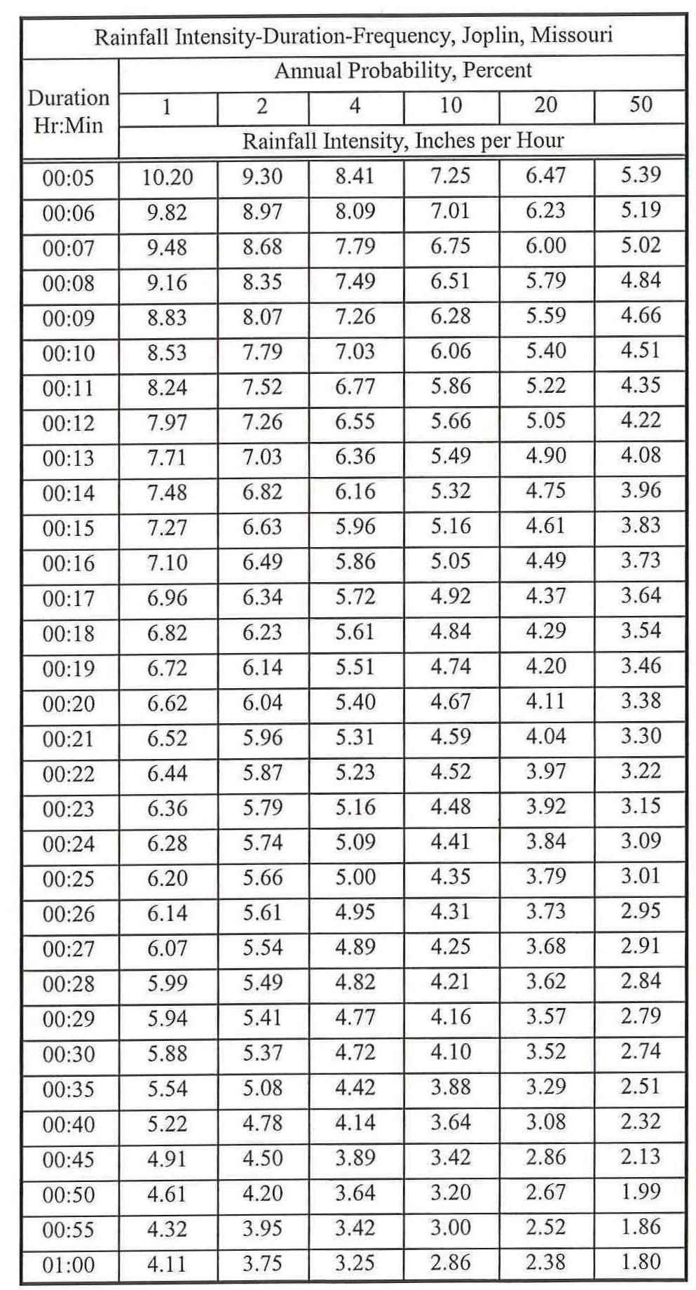
58 RAINFALL DATA TABLE INTENSITY-DURATION-FREQUENCY TABLE A

59 Source: Bulletin 71, Rainfall Frequency Atlas of the Midwest, Huff and Angel, 1992 National Weather Service Hydro 35, Five to 60-Minute Precipitation Frequency for the Eastern and Central United States, RAINFALL DATA TABLE DEPTH-DURATION-FREQUENCY TABLE A, Continued

60 HUFF S QUARTILE RAINFALL DISTRBUTIONS TABLE B
LAWRENCE, KANSAS STORMWATER MANAGEMENT CRITERIA
 LAWRENCE, KANSAS STORMWATER MANAGEMENT CRITERIA FEBRUARY 1996 CITY OF LAWRENCE, KANSAS STORMWATER MANAGEMENT CRITERIA TABLE OF CONTENTS Pg 1.0 GENERAL 1.1 Introduction... 1 1.2 Applicability... 1 1.3 General
Standards for Soil Erosion and Sediment Control in New Jersey May 2012 STANDARD FOR SLOPE PROTECTION STRUCTURES. Definition
 STANDARD FOR SLOPE PROTECTION STRUCTURES Definition Structures to safely conduct surface runoff from the top of a slope to the bottom of the slope. Purpose The purpose of this practice is to convey storm
SECTION 3 DRAINAGE. 3-1 General. 3-2 Drainage Ordinances and Legal Requirements
 SECTION 3 DRAINAGE 3-1 General All Drainage plans for proposed development shall be prepared by a Professional Engineer registered in Virginia, except as noted below. Further, their seal and signature
Stormwater Local Design Manual For Houston County, Georgia
 Stormwater Local Design Manual For Houston County, Georgia Adopted November 15, 2005 TABLE OF CONTENTS 1. FORWARD... 1 2. GENERAL LEVEL OF SERVICE STANDARDS... 2 2.1. DETENTION REQUIREMENTS... 2 2.1.1.
MODEL Stormwater Local Design Manual. City of Centerville
 MODEL Stormwater Local Design Manual City of Centerville Adopted December 6, 2005 TABLE OF CONTENTS 1. FORWARD... 1 2. GENERAL LEVEL OF SERVICE STANDARDS... 1 2.1. DETENTION REQUIREMENTS... 1 2.1.1. Discharge
NEW CASTLE CONSERVATION DISTRICT. through. (Name of Municipality) PLAN REVIEW APPLICATION DRAINAGE, STORMWATER MANAGEMENT, EROSION & SEDIMENT CONTROL
 PLAN REVIEW APPLICATION DRAINAGE, STORMWATER MANAGEMENT, EROSION & SEDIMENT CONTROL") NEW CASTLE CONSERVATION DISTRICT through (Name of Municipality) PLAN REVIEW APPLICATION DRAINAGE, STORMWATER MANAGEMENT, EROSION & SEDIMENT CONTROL Office use only: Received by Municipality: Received by
NEW CASTLE CONSERVATION DISTRICT through (Name of Municipality) PLAN REVIEW APPLICATION DRAINAGE, STORMWATER MANAGEMENT, EROSION & SEDIMENT CONTROL Office use only: Received by Municipality: Received by
CITY OF TROY DESIGN STANDARDS AND CONSTRUCTION SPECIFICATIONS
 CITY OF TROY DESIGN STANDARDS AND CONSTRUCTION SPECIFICATIONS PREPARED BY: F-7587 JANUARY 2010 TABLE OF CONTENTS SECTION 1 SECTION 2 SECTION 3 SECTION 4 SECTION 5 SECTION 6 APPENDIX ROADWAY DESIGN DRAINAGE
Stormwater Management Studies PDS Engineering Services Division ES Policy # 3-01
 Stormwater Management Studies PDS Engineering Services Division Revised Date: 2/28/08 INTRODUCTION The City of Overland Park requires submission of a stormwater management study as part of the development
Chapter 7. Street Drainage. 7.0 Introduction. 7.1 Function of Streets in the Drainage System. 7.2 Street Classification
 7. Introduction This chapter summarizes methods to evaluate runoff conveyance in various street cross sections and curb types in the Town of Castle Rock and identifies acceptable upper limits of street
Project Drainage Report
 Design Manual Chapter 2 - Stormwater 2A - General Information 2A-4 Project Drainage Report A. Purpose The purpose of the project drainage report is to identify and propose specific solutions to stormwater
CHECKLIST FOR STREETS, INLETS, AND STORM SEWER DESIGN
 CHECKLIST FOR STREETS, INLETS, I. STREET CLASSIFICATION AND DESIGN CRITERIA A. Determine drainage classification for the roadway section using Table 7-1 or Table 7-2. B. Determine the allowable flow depth
Contact the Jurisdictional Engineer for materials allowed by each jurisdiction.
 Design Manual Chapter 3 - Sanitary Sewers 3C - Facility Design 3C-1 Facility Design A. Capacity of Pipe Pipe sizes 15 inches and smaller should carry the peak flow at a depth of no more than 0.67 of the
Municipal Stormwater Ordinances Summary Table
 APPENDIX F Municipal Ordinances Summary Table Municipality Abington Bryn Athyn Borough Hatboro Borough Ordinance, SALDO Runoff equals pre post Erosion Sediment Control Water Quality Requirements Any which
Chapter 6. Hydrology. 6.0 Introduction. 6.1 Design Rainfall
 6.0 Introduction This chapter summarizes methodology for determining rainfall and runoff information for the design of stormwater management facilities in the City. The methodology is based on the procedures
DIVISION 5 STORM DRAINAGE CRITERIA
 DIVISION 5 STORM DRAINAGE CRITERIA Section 5.01 GENERAL The following storm drainage design criteria shall apply to all storm drainage designs in the City. Additional design criteria are specified in the
6.0 Runoff. 6.1 Introduction. 6.2 Flood Control Design Runoff
 October 2003, Revised February 2005 Chapter 6.0, Runoff Page 1 6.1 Introduction 6.0 Runoff The timing, peak rates of discharge, and volume of stormwater runoff are the primary considerations in the design
APPENDIX G HYDRAULIC GRADE LINE
 Storm Drainage 13-G-1 APPENDIX G HYDRAULIC GRADE LINE 1.0 Introduction The hydraulic grade line is used to aid the designer in determining the acceptability of a proposed or evaluation of an existing storm
CITY OF ASTORIA PUBLIC WORKS ENGINEERING DIVISION ENGINEERING DESIGN STANDARDS FOR IN-FILL DEVELOPMENT
 CITY OF ASTORIA PUBLIC WORKS ENGINEERING DIVISION ENGINEERING DESIGN STANDARDS FOR IN-FILL DEVELOPMENT Adopted by City Council: May 21, 2007 X:\General Eng\DESIGN STANDARDS\Engineering Design Standards
Ponds. Pond A water impoundment made by excavating a pit, or constructing a dam or an embankment.
 POND SITE SELECTION AND CONSTRUCTION Uses, Planning, & Design David Krietemeyer Area Engineer USDA-NRCS June 20, 2008 Uses Considerations for Location of Commonly Used Terms Pond A water impoundment made
Sediment Basin. Fe= (Depends on soil type)
") 3.9 Sediment Control Description: A sediment basin is an embankment with a controlled outlet that detains stormwater runoff, resulting in the settling of suspended sediment. The basin provides treatment
3.9 Sediment Control Description: A sediment basin is an embankment with a controlled outlet that detains stormwater runoff, resulting in the settling of suspended sediment. The basin provides treatment
APPENDIX C INLETS. The application and types of storm drainage inlets are presented in detail in this Appendix.
 Storm Drainage 13-C-1 APPENDIX C INLETS 1.0 Introduction The application and types of storm drainage inlets are presented in detail in this Appendix. 2.0 Inlet Locations Inlets are required at locations
E. STORMWATER MANAGEMENT
 E. STORMWATER MANAGEMENT 1. Existing Conditions The Project Site is located within the Lower Hudson Watershed. According to the New York State Department of Environmental Conservation (NYSDEC), Lower Hudson
Lyon Creek Cedar Way Stormwater Detention Dam Operation and Maintenance Manual
 Lyon Creek Cedar Way Stormwater Detention Dam Operation and Maintenance Manual Prepared by: Mike Shaw Stormwater Program Manager City of Mountlake Terrace January 2010 Section I General Information This
10.0 Storm Sewer Systems
 October 2003 Chapter 10.0, Storm Sewer Systems Page 1 10.0 Storm Sewer Systems 10.1 Introduction A storm sewer system consists of a system of inlets, pipes, manholes, junctions, cleanouts, outlets, and
2A Stormwater Regulations and Permitting A. Iowa Drainage Law and Resources 1 B. Regulated Activities 1
 Design Manual Chapter 2 - Stormwater Table of Contents TOC Table of Contents Chapter 2 - Stormwater 2A General Information 2A-1--------------------------------General Information A. Concept... 1 B. Informing
Standards for Soil Erosion and Sediment Control in New Jersey May 2012 STANDARD FOR RIPRAP. Conditions Where Practice Applies
 STANDARD FOR RIPRAP Definition A layer of loose rock, aggregate, bagged concrete, gabions, or concrete revetment blocks placed over an erodible soil surface. Purpose The purpose of riprap is to protect
CHAPTER 3 STORMWATER HYDROLOGY. Table of Contents SECTION 3.1 METHODS FOR ESTIMATING STORMWATER RUNOFF
 CHAPTER 3 STORMWATER HYDROLOGY Table of Contents SECTION 3.1 METHODS FOR ESTIMATING STORMWATER RUNOFF 3.1.1 Introduction to Hydrologic Methods...3.1-1 3.1.2 Symbols and Definitions...3.1-3 3.1.3 Rainfall
Location Drainage Study
 Location Drainage Study PROJECT ROUTE: LIMITS: MUNICIPALITY/COUNTY: JOB NUMBER: IL 47 at Burlington Road 750ft NW to 750ft SE of IL 47(Burlington), & 1000ft S to 1000ft N of Burlington (IL47) Kane County
City of Redwood City Stormwater Pollution Prevention Program. Drainage Guidelines for Residential Development
 City of Redwood City Stormwater Pollution Prevention Program Drainage Guidelines for Residential Development General Requirements A. Plot & Finished Grading Plan must be submitted with Building Permit
SECTION 4 SURFACE WATER MANAGEMENT DESIGN AND CONSTRUCTION REQUIREMENTS
 SECTION 4 SURFACE WATER MANAGEMENT DESIGN AND CONSTRUCTION REQUIREMENTS Page 4-1 INTRODUCTION 4-3 4-1.01 Applicability of VMCs 14.24, 14.25, 14.26 4-4 4-1.02 Minimum Requirements - Projects Below Threshold
Richland County Department of Public Works Engineering (Land Development) Division
 Division") Richland County Department of Public Works Engineering (Land Development) Division Commercial Projects What is a Commercial Project? Projects that are not related to residential single family homes and/or
Richland County Department of Public Works Engineering (Land Development) Division Commercial Projects What is a Commercial Project? Projects that are not related to residential single family homes and/or
Constructed Wetland Pond T-8
 Constructed Wetland Pond T-8 Description A constructed wetlands pond is a shallow retention pond designed to permit the growth of wetland plants such as rushes, willows, and cattails. Constructed wetlands
City of Saint John. Storm Drainage Design Criteria Manual
 Storm Drainage Design Criteria Manual March 7, 2016 LIST OF 2016 REVISIONS PAGES SECTION TITLE iii, iv, v, vi All Table of Contents 31-35 3 SUBMISSION REQUIREMENTS March 7, 2016 Page i DISCLAIMER The material
City of Elgin SUBDIVISION FINAL ENGINEERING Engineering Submittal Checklist
 If this is a re-submittal, please provide a point-by-point response to previous review comments, identifying how each comment has been addressed, location in the plan set of the changes made to address
At least 2 feet above the seasonal high water table Overflow path or structure provided
 General Conditions Map of proposed subwatershed to each subbasin, including total area and CN Design Flow or Design Volume to each STF, as appropriate Operation and Maintenance instructions for each STF
Erosion & Sedimentation Control Policy
 Issue Date 10/22/2010 Page 1 of 8 Erosion & Sedimentation Control Policy Introduction: Soil erosion is the removal of soil by water, wind, ice or gravity and sediment deposition occurs when the rate of
Table of Contents. 5-5 Release Rates Year Allowable Release Rate WQCV Release Rate EURV Release Rate...
 Chapter 5 Table of Contents 5-1 Introduction... 1 5-1-1 Stormwater Quality Considerations... 1 5-1-2 Stormwater Volume Considerations... 2 5-1-3 Downstream Impacts... 2 5-2 Requirements... 2 5-2-1 General
COON CREEK WATERSHED DISTRICT PERMIT REVIEW. Spring Lake Park Schools Westwood Middle School st Avenue NE, Spring Lake Park, MN 55432
 PAN 16-112, Westwood Middle School, Page 1 of 6 COON CREEK WATERSHED DISTRICT PERMIT REVIEW MEETING DATE: August 22, 2016 AGENDA NUMBER: 10 FILE NUMBER: 16-112 ITEM: Westwood Middle School RECOMMENDATION:
UPRR criteria for sizing waterway openings under bridges and through culverts are as follows:
 UNION PACIFIC RAILROAD SCOPE OF HYDROLOGIC/HYDRAULIC DESIGN ENGINEERING AND PERMITTING SERVICES FOR SIZING WATERWAY OPENINGS AT NEW AND REPLACEMENT STRICTURES These flood passage criteria were developed
SPECIFICATIONS FOR STREET CONSTRUCTION WITHIN THE TOWN OF PLAINVILLE
 SPECIFICATIONS FOR STREET CONSTRUCTION WITHIN THE TOWN OF PLAINVILLE BE IT ORDAINED by the Town Council of the Town of Plainville: SECTION 1. SUBDIVISIONS. All subdivisions hereinafter developed within
Understanding Stormwater Pollution Prevention Plans (SWPPPs) (SWPPPS)
 (SWPPPS)") Understanding Stormwater Pollution Prevention Plans (SWPPPs) (SWPPPS) Definitions SWPPP: Storm Water Pollution Prevention Plan BMP: Best Management Practice(s) to control pollution IDNR: Iowa Department
Understanding Stormwater Pollution Prevention Plans (SWPPPs) (SWPPPS) Definitions SWPPP: Storm Water Pollution Prevention Plan BMP: Best Management Practice(s) to control pollution IDNR: Iowa Department
Chatham Park Stormwater Manual
 Chatham Park Stormwater Manual Table of Contents A. Introduction... 2 B. Calculation Methods... 2 C. BMP Design Standards... 3 D. Compliance Points... 3 E. Critical Environmental Resources... 3 F. Submittal
Gwinnett County Stormwater System Assessment Program
 Gwinnett County Stormwater System Assessment Program Jonathan Semerjian, PE Dept. of Water Resources Stormwater Management Sam Fleming, PE Dewberry Presentation Overview Project Background Drivers Enhanced
Section 600 Runoff Table of Contents
 Section 600 Runoff Table of Contents 601 INTRODUCTION...600-1 602 RATIONAL METHOD...600-1 602.1 Rational Method Formula...600-2 602.2 Time of Concentration...600-2 602.3 Intensity...600-4 602.4 Runoff
Chapter 6 Hydrology TABLE OF CONTENTS CHAPTER 6 - HYDROLOGY
 Chapter 6 Hydrology TABLE OF CONTENTS CHAPTER 6 - HYDROLOGY... 6-1 6.1 Introduction... 6-1 6.1.1 Objective... 6-1 6.1.2 Definition... 6-1 6.1.3 Factors Affecting Floods... 6-1 6.1.4 Sources of Information...
Standards for Soil Erosion and Sediment Control in New Jersey May 2012 STANDARD FOR GRASSED WATERWAYS. Definition. Purpose
 STANDARD FOR GRASSED WATERWAYS Definition A natural or constructed watercourse shaped or graded in earth materials and stabilized with suitable vegetation for the safe conveyance of runoff water. Purpose
iswm TM Technical Manual Hydrology:
 : 1.0 2.0 Downstream Assessment 3.0 Streambank Protection 4.0 Water Balance 5.0 Rainfall Tables 6.0 Hydrologic Soils Data Table of Contents 1.0... HO-1 1.1 Estimating Runoff... HO-1 1.1.1 Introduction
Storm Drain Inlet Protection
 Categories EC Erosion Control SE Sediment Control TC Tracking Control WE Wind Erosion Control Non-Stormwater NS Management Control Waste Management and WM Materials Pollution Control Legend: Primary Category
Chapter 12 Storage. Contents. Overview... 1
 Chapter 12 Storage Contents Overview... 1 Implementation of Regional, Sub-regional, and On-site Detention Facilities... 2 Regional Detention... 2 Subregional Detention... 5 Onsite Detention... 6 Detention
Constructed Wetland Channel T-9
 Description A constructed wetland channel is a conveyance BMP that is built, in part, to enhance stormwater quality. Constructed wetland channels use dense vegetation to slow down runoff and allow time
2C-12 Detention Basin Outlet Structures
 Iowa Stormwater Management Manual 2C-12 2C-12 Detention Basin Outlet Structures A. Introduction The methods described in Section 2C-9 are used to estimate the volume of the detention storage. The second
3.0 DESIGN CRITERIA FOR SANITARY SEWER FACILITIES
 3.0 DESIGN CRITERIA FOR SANITARY SEWER FACILITIES All sanitary sewers shall be designed in accordance with these Design Standards, LBWD Rules and Regulations, and to accepted engineering principles. In
CITY OF DICKINSON DRAINAGE CRITERIA MANUAL. (Adopted August 23, 2011)
") CITY OF DICKINSON DRAINAGE CRITERIA MANUAL () I. INTRODUCTION Purpose This DRAINAGE CRITERIA MANUAL (the Manual ) provides design guidance for use by developers and engineers in preparation of drainage
CITY OF DICKINSON DRAINAGE CRITERIA MANUAL () I. INTRODUCTION Purpose This DRAINAGE CRITERIA MANUAL (the Manual ) provides design guidance for use by developers and engineers in preparation of drainage
CHAPTER 12 BRIDGE DECK DRAINAGE SYSTEMS
 OFFICE OF STRUCTURES MANUAL FOR HYDROLOGIC AND HYDRAULIC DESIGN CHAPTER 12 BRIDGE DECK DRAINAGE SYSTEMS APRIL 2011 APRIL 2011 Page 1 Chapter Table of Contents 12.1 Policy... 12-3 12.1.1 Table 1... 12-3
Pre-Treatment Bioretention Cells Bioswales IOWA STORMWATER MANAGEMENT MANUAL DECEMBER 16, 2015
 Pre-Treatment Bioretention Cells Bioswales IOWA STORMWATER MANAGEMENT MANUAL DECEMBER 16, 2015 Urban Runoff Background How we got here What Problem?? Provenance of the Problem Unified Sizing Criteria What
ARTICLE A. POST-DEVELOPMENT STORMWATER MANAGEMENT FOR NEW DEVELOPMENT AND REDEVELOPMENT
 CHAPTER 11. STORMWATER MANAGEMENT ARTICLE A. POST-DEVELOPMENT STORMWATER MANAGEMENT FOR NEW DEVELOPMENT AND REDEVELOPMENT DIVISION 1. GENERALLY Sec. 10-11001. FINDINGS It is hereby determined that: (1)
CLARK COUNTY REGIONAL FLOOD CONTROL DISTRICT HYDROLOGIC CRITERIA AND DRAINAGE DESIGN MANUAL
 CLARK COUNTY REGIONAL FLOOD CONTROL DISTRICT HYDROLOGIC CRITERIA AND DRAINAGE DESIGN MANUAL SECTION 600 STORM RUNOFF TABLE OF CONTENTS 601 INTRODUCTION 603 601.1 - Basin Characteristics 603 602 TIME OF
Chapter 9 - Storm Drains
 Chapter 9 - Storm Drains TABLE OF CONTENTS CHAPTER 9 - STORM DRAINS... 9-1 9.1 Introduction... 9-1 9.1.1 Objective 9-1 9.2 Design Policy... 9-2 9.2.1 Definition 9-2 9.2.2 General Policies... 9-2 9.3 Design
Temporary Watercourse Crossing: Culverts
 Temporary Watercourse Crossing: Culverts DRAINAGE CONTROL TECHNIQUE Low Gradient Velocity Control Short Term Steep Gradient Channel Lining Medium-Long Term Outlet Control Soil Treatment Permanent Symbol
STORMWATER RUNOFF AND WATER QUALITY IMPACT REVIEW
 SUBCHAPTER 8 STORMWATER RUNOFF AND WATER QUALITY IMPACT REVIEW 7:45-8.1 Purpose and scope of review Except for those projects expressly exempted by this chapter or waived by the Commission, the Commission
SECTION TRENCHING & BACKFILLING
 SECTION 02225 - TRENCHING & BACKFILLING 1.0 GENERAL 1.1 Work included in this Section includes trenching and backfilling for underground pipelines and related structures only. 1.2 Reference Specifications
PART 1 GENERAL REQUIREMENTS
 PART 1 GENERAL REQUIREMENTS Contract Closeout Plan 110 Arrow diagram for project close-out...3 Erosion Control 121 Straw bale barrier... 5 122 Silt fence... 7 123 Diversion dike... 9 124 Inlet protection...
APPENDIX IV. APPROVED METHODS FOR QUANTIFYING HYDROLOGIC CONDITIONS OF CONCERN (NORTH ORANGE COUNTY)
") APPENDIX IV. APPROVED METHODS FOR QUANTIFYING HYDROLOGIC CONDITIONS OF CONCERN (NORTH ORANGE COUNTY) Hydromodification design criteria for the North Orange County permit area are based on the 2- yr, 24-hr
APPENDIX IV. APPROVED METHODS FOR QUANTIFYING HYDROLOGIC CONDITIONS OF CONCERN (NORTH ORANGE COUNTY) Hydromodification design criteria for the North Orange County permit area are based on the 2- yr, 24-hr
CHAPTER 9 STORMWATER MANAGEMENT PLAN REQUIREMENTS
 CHAPTER 9 9.1 INTRODUCTION The Virginia Stormwater Management Program (VSMP) Act and Regulations require that Henrico County adopt a local program to administer the requirements. The requirements are addressed
City of Oakland. Public Works Agency Standards STORM DRAINAGE DESIGN GUIDELINES. Engineering Design & ROW Management Division
 City of Oakland PUBLIC WORKS AGENCY 250 FRANK H. OGAWA PLAZA 4 TH FLOOR OAKLAND, CALIFORNIA 94612 (510) 238-3437 FAX (510) 238-7227 TTD (510) 238-3254 Public Works Agency Standards STORM DRAINAGE DESIGN
The City of North Las Vegas (CNLV) does not allow valley gutters to be constructed across streets with right-of-way widths of 80 feet or greater.
 does not allow valley gutters to be constructed across streets with right-of-way widths of 80 feet or greater.") Background The City of rth Las Vegas strives to provide the development community with adequate information to ensure the successful completion of any project in the City. To aid in the submittal of a
Background The City of rth Las Vegas strives to provide the development community with adequate information to ensure the successful completion of any project in the City. To aid in the submittal of a
SOIL EROSION CONTROL PERMIT APPLICATION
 SOIL EROSION CONTROL PERMIT APPLICATION Pursuant to Part 91, Soil Erosion and Sedimentation Control, of Act 451 of the Public Acts of 1994, as amended A Soil Erosion Control Permit is required for earth
CHAPTER 6 ADDITIONAL STANDARDS APPLYING TO SHORELAND AREAS AND PUBLIC WATERS
 CHAPTER 6 ADDITIONAL STANDARDS APPLYING TO SHORELAND AREAS AND PUBLIC WATERS Section 1 Intent. 49 Section 2 Floodplain Requirements 49 Section 3 Water-Oriented Accessory Structures 50 Section 4 Stairways,
Storm Drain Inlet Protection for Construction Sites (1060)
") Storm Drain Inlet Protection for Construction Sites (1060) Wisconsin Department of Natural Resources Conservation Practice Standard I. Definition A temporary device installed in or around a storm drain
Storm Drain Inlet Protection for Construction Sites (1060) Wisconsin Department of Natural Resources Conservation Practice Standard I. Definition A temporary device installed in or around a storm drain
SECTION 11: REGULATORY FLOODWAYS
 SECTION 11: REGULATORY FLOODWAYS Contents 11.1. The Floodway... 11-2 11.1.1. The floodway concept... 11-2 11.1.2. Floodway map... 11-2 11.1.3. Floodway permitting... 11-3 11.1.4. Changing the floodway...
Town of Essex, Vermont January, 2017 Standard Specifications For Construction CHAPTER 3 EROSION AND SEDIMENT CONTROL
 CHAPTER 3 EROSION AND SEDIMENT CONTROL CHAPTER 3 EROSION AND SEDIMENT CONTROL Section 300 General Summary All projects constructed within the Town of Essex shall be constructed in strict accordance with
FENCES. This hand out is for REFERENCE ONLY. For more details see specific code sections.
 Village of Vernon Hills Community Development Department 290 Evergreen Drive, Vernon Hills, IL 60061 Phone 847-367-3704 - Fax 847-367-2541 - http:// www.vernonhills.org FENCES This hand out is for REFERENCE
MICHIGAN DESIGN MANUAL ROAD DESIGN CHAPTER 4 INDEX DRAINAGE
 CHAPTER 4 INDEX DRAINAGE Supplement to Chapter 4 4.01 GENERAL INFORMATION 4.01.01 References 4.01.03 General Procedures 4.02 STORM SEWER DESIGN 4.02.15 Sewer Bulkheads 4.02.18 Storm Sewers Under Structures
Stormwater Management Manual. Public Works Department City of Billings, Montana
 Stormwater Management Manual Public Works Department City of Billings, Montana Stormwater Management Manual Developed by Public Works Department City of Billings, Montana With assistance from Debi Meling,
Urban Drainage Introduction. A.Ramachandra Rao. C.B. Burke. T.T. Burke, Jr.
 32 Urban Drainage A.Ramachandra Rao Purdue University C.B. Burke Christopher B. Burke Engineering, Ltd. T.T. Burke, Jr. Christopher B. Burke Engineering, Ltd. 32.1 Introduction 32.2 The Rational Method
S.O.P. No. HMD
 Page: 1 of 9 PURPOSE: To establish (SOP) for submission requirements, review process and approval of applications for Non-vehicular Access Permits for the purpose of connection or discharge to any MassDOT
CONSTRUCTION SURVEY. Construction survey includes personnel, equipment, and supplies required for, but not limited to, the following:
 CONSTRUCTION SURVEY PART 1 - GENERAL 1.01 SECTION INCLUDES Construction survey includes personnel, equipment, and supplies required for, but not limited to, the following: A. Construction Survey: 1. Project
110 STORMWATER MANAGEMENT AND COLLECTION SYSTEMS
 110 STORMWATER MANAGEMENT AND COLLECTION SYSTEMS 110.01 DEFINITIONS 110.01.01 Detention structure. A permanent structure for the temporary storage of stormwater runoff that is designed so as not to create
SACHSE EROSION CONTROL GUIDELINES
 SACHSE EROSION CONTROL GUIDELINES Section I. Definitions The following words, terms, and phrases, when used in this guideline, shall have the meanings ascribed to them in this Section, except where the
Prepared for Urban Drainage and Flood Control District
 BERM FAILURE TECHNICAL ANALYSES SOUTH PLATTE GRAVEL PIT EVALUATION CRITERIA Prepared for Urban Drainage and Flood Control District Wright Water Engineers, Inc. January 2013 121-030.000 TABLE OF CONTENTS
APPLICATION FOR PUBLIC INFRASTRUCTURE PERMIT
 APPLICATION FOR PUBLIC INFRASTRUCTURE PERMIT Engineering Division 550 Landa Street New Braunfels, Texas 78130 (830) 221-4020 1. Subdivision Plat Name: Location Description/ Nearest Intersection: Acreage:
Storm Water Management Standards
 Storm Water Management Standards The City of Roseville has developed specific requirements that apply to development and redevelopment projects. These standards are intended to help achieve the water resource
SECTION CONSTRUCTION SERVICES
 SECTION 01100 CONSTRUCTION SERVICES PART 1 GENERAL 1.01 - Section Includes A. Mobilization. B. Construction Surveys. C. Record Documents. 1.02 Description Of Work A. Mobilization: includes the preparatory
TRANSPORTATION & PUBLIC WORKS DEPARTMENT TECHNICAL STANDARDS
 Athens-Clarke County Unified Government TRANSPORTATION & PUBLIC WORKS DEPARTMENT TECHNICAL STANDARDS JULY, 2009 PREFACE The technical standards presented herein reflect the current policies and practices
In preparation for constructing buildings on a property, the builder. Site Preparation CHAPTER
 CHAPTER 3 Site Preparation In preparation for constructing buildings on a property, the builder must consider a number of factors related to code requirements. The buildings must be located according to
Index. Page numbers followed by f indicate figures.
 Index Aerodynamic method, 103, 110 111 Algae, 131, 173, 175 Alternate depth, 88 Alternating block method, 132, 140 141 Attenuation, 106, 107f, 118, 120 Page numbers followed by f indicate figures. Baseflow
ARTICLE XII RECREATIONAL VEHICLE PARK REGULATIONS
 ARTICLE XII RECREATIONAL VEHICLE PARK REGULATIONS ARTICLE XII RECREATIONAL VEHICLE PARK REGULATIONS Section 1201 Applicability For the purpose of this Article, recreation vehicles and recreational vehicle
Overview of NRCS (SCS) TR-20 By Dr. R.M. Ragan
 TR-20 By Dr. R.M. Ragan") Overview of NRCS (SCS) TR-20 By Dr. R.M. Ragan TR-20 is a computer program for the simulation of runoff occurring from a single storm event. The program develops flood hydrographs from runoff and routes
Overview of NRCS (SCS) TR-20 By Dr. R.M. Ragan TR-20 is a computer program for the simulation of runoff occurring from a single storm event. The program develops flood hydrographs from runoff and routes
SECTION 4 - DESIGN STANDARDS FOR WATER DISTRIBUTION FACILITIES
 SECTION 4 - DESIGN STANDARDS FOR WATER DISTRIBUTION FACILITIES 4.1 GENERAL REQUIREMENTS 4.1.1 Water and fire protection distribution facilities are to be provided solely for the purpose of supplying potable
TECHNICAL CONTENT PROPOSED STEEP SLOPE REGULATION
 1 TECHNICAL CONTENT PROPOSED STEEP SLOPE REGULATION Draft 2/08/10 (Revised 02-14-11,Revised 02-21-11, Revised 03-03-11, Revised 04-19-11, Revised 04-20-11, Revised 05-05-11, Revised 05-09-11). DEFINITIONS
f) Culverts in series shall be spaced at least 20 feet between each other. 2.7 C Culverts
 Culverts in series shall be spaced at least 20 feet between each other. 2.7 C Culverts") 2.7 C Culverts 1. General Culverts are intended to safely pass flow under road crossings. Criteria are designed to protect, maintain, and enhance public health, safety, and the environment. Where culverts
2.7 C Culverts 1. General Culverts are intended to safely pass flow under road crossings. Criteria are designed to protect, maintain, and enhance public health, safety, and the environment. Where culverts
Chapter 7 Ditches and Channels
 Chapter 7 Ditches and Channels TABLE OF CONTENTS CHAPTER 7 - DITCHES AND CHANNELS... 7-1 7.1 Introduction... 7-1 7.2 Design Policy... 7-2 7.2.1 Federal Policy... 7-2 7.2.2 Commonwealth of Virginia Policy...
CHAPTER 8 EROSION AND SEDIMENT CONTROL PLAN REQUIREMENTS
 CHAPTER 8 EROSION AND SEDIMENT CONTROL PLAN REQUIREMENTS 8.1 INTRODUCTION To minimize the detrimental effects of erosion and sedimentation, Henrico County requires that those individuals responsible for
Hydraulic Design of Highway Culverts HDS 5 September 1985
 Hydraulic Design of Highway Culverts HDS 5 September 1985 Welcome to HDS 5 - Hydraulic Design of Highway Culverts Table of Contents Preface Tech Doc U.S. - SI Conversions DISCLAIMER: During the editing
The Islamic University of Gaza- Civil Engineering Department Sanitary Engineering- ECIV 4325 L5. Storm water Management
 The Islamic University of Gaza- Civil Engineering Department Sanitary Engineering- ECIV 4325 L5. Storm water Management Husam Al-Najar Storm water management : Collection System Design principles The Objectives
FINDINGS: Olsson used a three-step analysis strategy to develop a benefit cost ratio that would indicate the relative feasibility of this project.
 EXECUTIVE SUMMARY FINDINGS: Based on the results of this feasibility study, the Platte Republican Diversion Project would be cost-effective. With minimal improvements to the channel, and the existing bridge
Zoning Permits 11-1 ZONING PERMITS
 Zoning Permits 11-1 ZONING PERMITS (a) Building or structures shall be started, repaired, reconstructed, enlarged or altered only after a zoning permit has been obtained from the administrator and a building
SUBSURFACE INFILTRATION SYSTEM DESCRIPTION. Alternative Names: Sump, Drywell, Infiltration Trench, Infiltration Galleries, Leach Fields
 4.1-d SUBSURFACE INFILTRATION SYSTEM Alternative Names: Sump, Drywell, Infiltration Trench, Infiltration Galleries, Leach Fields BMP DESIGN APPROACH Pollutant Source Control Hydrologic Source Control Stormwater
CHAPTER 13 R-5 MANUFACTURED MOBILE HOME PARK RESIDENTIAL DISTRICT
 15.1300 CHAPTER 13 R-5 MANUFACTURED MOBILE HOME PARK RESIDENTIAL DISTRICT 15.1301 SECTION 13.01 STATEMENT OF PURPOSE To provide for manufactured home park development, of long-term duration of stay, in