CONTACT INFORMATION. Questions concerning sewage disposal or water supply (Chapters 11 and 12, Appendices VI and VII):
|
|
|
- Morgan Stella Lang
- 6 years ago
- Views:
Transcription

1 IMPROVEMENT STANDARDS OCTOBER 2006
2 CONTACT INFORMATION Questions concerning road construction and storm drainage design (Chapters 1 through 10, Appendices I through V, VIII and IX, copies of standards printed or on CD): Butte County Public Works, Land Development Division, 7 County Center Drive, Oroville, CA Telephone: (530) , Fax (530) Web: sedell@buttecounty.net Questions concerning sewage disposal or water supply (Chapters 11 and 12, Appendices VI and VII): Butte County Public Health, Environmental Health Division, 7 County Center Drive, Oroville, CA Telephone: (530) , Fax (530) EHpermits@buttecounty.net Questions concerning fire protection (Chapter 13): California Department of Forestry and Fire Protection, Butte County Fire Department, 176 Nelson Avenue, Oroville, CA Telephone: (530) , Office Fax (530) , web: Darren.Read@fire.ca.gov, Fire Protection Planning Steve.Fowler@fire.ca.gov, Fire Marshal Questions concerning land use, zoning or general plan: Department of Development Services, Planning Division, 7 County Center Drive, Oroville, CA Telephone (530) , Fax (530) Web: dsplanning@buttecounty.net Questions concerning building: Plan Checking, Construction Requirements, Building Codes & County Inspections, Development Services, Building Division, 7 County Center Drive, Oroville, CA Telephone: (530) , Fax (530) Web: dsbuilding@buttecounty.net
3 TABLE OF CONTENTS REVISED IMPROVEMENT STANDARDS FOR SUBDIVISIONS, PARCEL MAPS AND SITE IMPROVEMENTS PURSUANT TO CHAPTER 20 OF THE BUTTE COUNTY CODE 1.0 PURPOSE DEFINITIONS GENERAL REQUIREMENTS STANDARD SHEETS AND SCALES PLAN DETAILS INSPECTION DURING CONSTRUSTION FINAL INSPECTION AS-BUILT PLAN STREETS AND HIGHWAYS STORM DRAINAGE SEWAGE DISPOSAL WATER SUPPLY FIRE STANDARDS 47 1
4 APPENDIXES APPENDIX I URBAN AREA MAPS OR SPECIAL AREA MAPS Chico Urban Area 1 North Quadrant 1A East Quadrant 1B South Quadrant 1C West Quadrant 1D Chapman Mulberry Area 2 Chico Vecino Drainage Area 3 Chico Vecino Road Improvements 4 North Chico Specific Plan 5 Durham Urban Area 6 Gridley Urban Area 7 Oroville Urban Area 8 Paradise Urban Area 9 Mountain Recreational Area 10 California Department of Forestry State Responsibility Area (SRA) 11 California Department of Forestry High and Very High Fire Areas 12 APPENDIX II SUBDIVISION ROAD STANDARDS Typical Section for Commercial and Industrial Subdivisions RS-1 Typical Road Sections for All Urban Land Divisions RS-2 Typical Road Sections for Rural Subdivisions RS-3 Typical Road Sections for Subdivisions within Mountain Recreation Area RS-4 Typical Section for Frontage Roads RS-5 Typical Section for Mountain Recreation Subdivision Private Road Improvement RS-6 Typical Section for Rural Subdivision Private Road Improvement RS-7 Typical Sections for Non-Urban Area Land Divisions RS-8-LD (I to IV) Typical Sections for Chapman/Mulberry Neighborhood Plan Northeast End Jackson Street (Wisconsin Street to End) CM-1 Typical Sections for Chapman/Mulberry Neighborhood Plan Davis Street, Martin Street, Madison Street, Wisconsin Street, Colorado Street, California Street, Jackson Street, B Street, Mulberry Street, Laurel Street, Fetter Street CM-2 Typical Sections for Chapman/Mulberry Neighborhood Plan East Tenth Street, Linden Street, Willow Street, Bartlett Street, Guill Street, Ohio Street, Elm Street, 21 st Street, 22 nd Street, 23rd Street CM-3 Typical Sections for Chapman/Mulberry Neighborhood Plan Humboldt Avenue CM-4 2
5 Typical Sections for Chapman/Mulberry Neighborhood Plan C Street, 16 th Street Typical Sections for Chapman/Mulberry Neighborhood Plan Bruce Street Typical Sections for Chapman/Mulberry Neighborhood Plan Virginia Street, Cleveland Street Typical Sections for Chapman/Mulberry Neighborhood Plan Boucher Avenue CM-5 CM-6 CM-7 CM-8 Arterial Type A-II Hicks Lane Eaton to Village Core NCSP-1 Arterial Type A-III New Arterial Hicks Lane to Mud Creek NCSP-2 Arterial Type A-IV New Arterial Mud Creek to Highway 99 Keefer Road Hicks Lane to Highway 99 Hicks Lane Eaton Road to Caballo Way Garner Lane Keefer Road to Highway 99 NCSP-3 Collector Type C-1 Village Core Collector NCSP-4 Collector Type C-1I Hicks Lane Keefer Road to Mud Creek NCSP-5 Local Type L-I Local Streets in M-1 & M-2 Zones NCSP-6 Local Type L-II Local Streets in R-1, R-2 & R-3 Zones NCSP-7 Local Type L-III Local Streets in SR-1 & SR-3 Zones NCSP-8 Local Type L-IV Cul-de-sac Streets in R-1, R-2 & R-3 Zones NCSP-9 Local Type L-V Cul-de-sac & Local Streets in SR-1 & SR-3 Zones NCSP-10 Local Type L-VI One Way Loop Street NCSP-11 Local Type L-VII Alleys in R-1 & R-2 Zones NCSP-12 APPENDIX III STANDARD DETAILS Typical Sections for: Vertical and Rolled Curb, Gutter and Sidewalk S-1 Typical Sections for Concrete: Vertical and Rolled Curb and Gutter S-2 Concrete Residential Driveway Approach S-3 Concrete Commercial Driveway Approach S-3A Cross Sections - Concrete Commercial Driveway Approach S-3B Standard Cross Gutter S-4 Concrete Pedestrian Ramp Type A S-5 Detectable Warning Surface S-5A Concrete Pedestrian Ramp Type B S-6 Typical Headwall Structural Details S-7 Type Go Drainage Inlet and Details S-8 Modified Type Go Drainage Inlet Side Opening S-8A Modified Type Go Drainage Inlet and Details Checker Plate S-8B Type Go Drainage Inlet and Details No Curb S-8C Type C Inlet S-9 Concrete Trench Cover for Streets and Sidewalks S-10 Street Survey Monument S-11 Standard Survey Control Monument S-11A County Road Sign S-12 Private Road Sign S-12A Street and Stop Sign Post Details County Right of Way S-13 Street Name Sign Post Details Private Road S-13A 3
6 Temporary Cul-de-sac S-14 Permanent Cul-de-sac S-15 Offset Cul-de-sac S-15A Driveways for Rural Hillside Mountain Recreation Areas S-16 Typical Details of Pavement Replacement and Backfill Requirements S-17 Arterial Public Road Intersection S-18 Collector Public Road Connection S-18A Local Public Road Connection S-18B Standard Manhole S-19 Standard Drop Manhole S-20 Approved Methods of Laying Pipe S-21 Typical Method for Setting Appurtenances S-22 Standard Flushing Hole C.I. Frame and Cover S-23 Standard Manhole Frame and Cover Details S-24 Eccentric Manhole Details S-25 Eccentric Manhole for C-I-P-C-P S-26 Standard Fire Hydrant Installation S-27 Standard Fire Hydrants S-28 Swimming Pool and Water Tank Connection S-29 Guard Panel and Guard Post Details S-30 Private Driveway Details S-31 Concrete Private Driveway Behind Asphalt Dike Section S-31A Private Driveway Behind Asphalt Dike Section S-31B Cast-in-Place Concrete Pipe in Road or Street Right of Way S-32 Drainage Ditch Pipe Outlet Details S-33 Sacked Concrete Slope Protection with Storm Drain Installation into Channels S-34 Utility Trench Details S-35 Fences, Walls and Hedges CornerLot S-36 Fences, Walls and Hedges Interior Lot S-37 Typical Storm Drainage Leach Trench S-38 Typical Inlet to Leach Trench Connection S-39 Storm Water Management Program Drainage Inlet Marker S-40 Bicycle/Pedestrian Path Traffic Barrier Post S-41 Building Free Turn Around Area (Hammer Head T) S Speed Hump S-43 Speed Table S-44 APPENDIX IV DRAINAGE CHARTS Rainfall Intensity Oroville D-1 Rainfall Intensity Paradise D-2 Rainfall Intensity Chico D-3 Minimum Culvert Sizes for Given Q D-4 Values for Estimating Coefficient of Runoff C D-5 Headwater Depth Circular Pipe D-6 Headwater Depth Arch Pipe D-7 Maximum Velocities for Channel Lining D-8 4
7 Stone Size for Rip-Rap D-9 Culvert Cover D-10 Drainage Calculation Form D-11 Time of Concentration D-12 APPENDIX V SUBDIVISION AGREEMENT AND MAINTENANCE BOND Subdivision Agreement & Bonds 1 Maintenance Bond 3 APPENDIX VI Construction Standards for Small Community Water Supplies 1 CHART 1 - Maximum Day Demand Metered Water Systems 7 CHART 2 - Maximum Day Demand Flat Rate Water Systems 8 CHART 3 - Needed Storage Volume When Q=Qo Metered Water Systems 9 CHART 4 - Needed Storage Volume When Q=Qo Flat Rate Water Systems 10 APPENDIX VII Minimum Usable Lot Areas for Subdivisions and Land Divisions Where Individual Sewage Disposal Systems are to be used; Minimum Separation Distances 1 APPENDIX VIII Storm Drainage Fees County of Butte 1 Storm Drainage Fee Schedule Exhibit A Included 8 APPENDIX IX County Code Chapter 26 Article II 1 Additional Improvements Requirements for Certain Buildings in Specified Urban and Rural Areas 5
8 6
9 IMPROVEMENT STANDARDS FOR SUBDIVISIONS, PARCEL MAPS AND SITE IMPROVEMENTS PURSUANT TO CHAPTER 20 OF THE BUTTE COUNTY CODE 1.0 PURPOSE: 1.01 It is the purpose of these Improvement Standards to provide minimum standards to be applied to all site improvements, private and public works, as well as improvements to be installed within existing rights-of-way and easements. This is necessary in order to provide for coordinated development of required facilities to be used by and for the protection of the public. These standards shall apply to and regulate the design and preparation of plans for construction of streets, highways, alleys, drainage, sewerage, street lighting, water supply facilities, fire protection and related public improvements. ( Res ) 1.02 It is recognized that it is not humanly possible to anticipate all situations that may arise or to prescribe standards applicable to every situation. Therefore, any items or situation not included in these Improvement Standards shall be designed in accordance with accepted engineering practice, the Standard Specifications of the State of California Department of Transportation, and as specified by the Director of Public Works. 2.0 DEFINITIONS 2.01 In these Improvement Standards, the intent and meaning of the terms that are used shall be as defined in State Standard Specifications, and as herein specifically noted I Consulting Engineer - Any person or persons, firms, partnership or corporation legally authorized to practice civil, mechanical or electrical engineering in the State of California who prepares or submits improvement plans and specifications to the Department of Public Works of Butte County for approval Contractor - Shall mean any person or persons, firm, partnership, corporation, or combination thereof, licensed to perform the type of work involved, who has entered into a contract with any person, corporation, company, special district, of 1
10 the County of Butte as party or parties of the second part, or his or their legal representative, for the construction of any improvement or portions of any improvement within the County of Butte County - Shall mean County of Butte including special districts administered by County Board of Supervisors Department of Public Works - Shall mean the Department of Public Works of Butte County Developer - Shall mean any person or persons, firm, partnership, corporation, or combination thereof, financially responsible for the work involved Development - Shall mean single properties as well as subdivision improvement Director - Shall mean the Director of Public Works of Butte County acting either directly or through the Chiefs of the appropriate Divisions of the Department of Public Works of their authorized representatives. Director shall also mean the District Engineer where special districts are involved Engineer - Meaning shall be identical to the definition of Director as herein defined Laboratory - Shall mean any testing agency or testing firm, which has been approved by the Department of Public Works Site Improvement - Shall mean required improvements other than subdivisions Standard Specifications - Shall mean the last issued volume of the State of California Standard Specifications as issued by the Business and Transportation Agency, Department of Transportation, State of California State - As used in the State Specifications, shall mean Butte County State Standard Drawings - Shall mean the Standard Drawings and plans of the State of California, Business and Transportation Agency, Department of Transportation Zoning Classifications - Shall mean those zones established by and as listed in the Butte County Zoning Code GENERAL REQUIREMENTS: 3.01 Complete plans and specifications for all proposed streets, drainage facilities, sewerage, street lighting, water distribution systems, fire protection systems, industrial developments, subdivisions, and site improvements, including any 2
11 necessary dedications and easements shall be submitted to the Department of Public Works for approval and this approval must be substantiated by the signature of the Director prior to the beginning of construction of any such improvements. The Director or his representative shall order the Contractor to cease work on any project if said Contractor does not have properly approved plans in his possession. An encroachment permit, issued by the Department of Public Works, must be obtained by the Contractor prior to performing any work within the County right-of-way, easements, or drainage facilities. The Contractor shall be bonded as required, provide a certificate of insurance naming the County additionally insured, and meet the requirements of the County Code. All plans and specifications for improvements, which are to be accepted for maintenance by the County, shall be prepared by a Consulting Engineer of the appropriate branch of engineering covering the work submitted. ( Res ) 3.02 The Standard Specifications shall be made a part of contract documents by note of reference, which shall appear in the Special Provisions and in the General Notes of the plans. The not of reference shall be as follows: "The Standard Specifications are part of the contract documents of this project and all materials and construction shall be in strict conformance with said Standard Specifications or as authorized by these plans." 3.03 Two sets of plans, complete and in accordance with these Improvement Standards and the Standard Specifications, shall be submitted along with any required specifications, computations, test data, and other material requested by the Director, to the Department of Public Works for approval. Plan checking and inspection fees shall be paid prior to approval of plans. Should the development not be carried to completion any portion of the required deposit over and above the accumulated costs expended by the Department on the development will be refunded to the Developer. Should there be required alterations or revisions to the plans as submitted, the Director will return one copy with the required corrections marked or indicated thereon. If the plans submitted are not prepared in accordance with these Improvement Standards and the Standard Specifications or not in keeping with the standards of the profession, the Director may return them unmarked and unapproved. No plans will be approved nor construction authorized until such time as the Director signifies his approval as previously prescribed for the original plans. At such time as 3
12 the Consulting Engineer preparing the plans has made the necessary revisions and the plan check and inspection fees have been paid, the Director will sign the tracings in the space provided after the Consulting Engineer has signed them. The Consulting Engineer shall deliver the necessary sets of prints from the approved tracings to the Director Should changes become necessary during construction, the Consulting Engineer must obtain the consent of the Director and resubmit the plan sheets that are applicable. Necessary changes shall be clearly shown and dated on the plans. Minor changes, which do not affect the basic design or contract may be made upon the authorization of the Director but said changes must be shown on "asbuilt" plans when the contract is completed Excepted from approval are any features of the plans that are contrary to or conflict with or do not conform to any California State Law, Butte County Code or resolution or generally accepted good engineering practice, in keeping with the standards of the profession; even though such errors, omissions or conflict may have been overlooked in the Department of Public Works review of the plans If the developer elects to have a registered civil engineer or licensed land surveyor other than the engineer that prepared the plans provide the construction staking, he shall provide the Director in writing with the name of the individual or firm one week prior to the staking of the project for construction. The Developer shall then be responsible for providing professional engineering service for any plan changes which may be required during the construction phase and for the preparation of revised plans for changes if necessary and "as-built" plans upon completion of the construction Construction Staking A. Scope - It is the intent of this section to define the responsibilities of the Contractor regarding the use, maintenance, and replacement of construction stakes. The Developer's engineer will furnish the stakes and reference points for the improvements relative to the work and restaking as required by the County as listed in paragraph C of this section. B. Control Stakes - Control and reference stakes for all construction work shall be conspicuously flagged. The contractor shall be responsible for 4
13 the preservation and perpetuation of these points, marks, and stakes. If the removal of a control point, mark, or stake is required by the construction operations, the Contractor shall notify the Developer's engineer at least two (2) working days in advance of such operations. After such advance notice, the Developer s Engineer will perpetuate and remove said control point. C. Required Staking - The Developer's engineers will furnish the following stakes and reference marks. 1. Street Grading a. One set of slope stakes will be set at a maximum of fifty (50) foot intervals. Reference stakes will be set at an appropriate offset from the top of cut or toe of fill. The top of cut or toe of fill will not be staked. The reference stake will indicate the offset to the top of cut or toe of fill and indicate the cut or fill from the reference stakes will indicate the cuts or fills and distances from the top of cut or toe of fill to the subgrade hinge point and centerline subgrade elevation. b. At street intersections the radius points for pavement rounding will be staked. The elevation of the top of the stake will be established and marked on the witness lath. 2. Clearing When slope stakes are not required the following clearing stakes will be set: On streets and roads, lath marked CLEAR" will be set at 50' intervals at the clearing limits. The lath will be oriented so the marking faces the centerline of the road or street. 3. Sewer Sewer trunk lines will be staked on an appropriate offset from sewer centerline at fifty (50) foot intervals on tangents and twenty-five (25) foot intervals on horizontal and vertical curves. All manholes and curve points will be staked on an appropriate offset from the sewer centerline. These stakes will indicate the cut to the flow line of the sewer pipe. When a flow line grade is indicated on the plans for a 5
14 sewer service, a cut to the flow line at the end of the service will be marked on the offset stake or witness lath thereto. 4. Water The centerline of water mains shall be staked at 100' intervals on tangents and 25' on curves for horizontal alignment only. Hydrants will be marked by an offset stake. Front lot corners will be staked at an appropriate offset along the lot lines and it will be the responsibility of the Contractor to locate water services as shown on the plans relative to said offset front lot corners. 5. Curb and Gutter Stakes for curb and gutter will be set no more than 5' from the proposed work and maximum of 25' intervals. Subgrade, string line and forms shall be checked by the inspector prior to placing curb and gutter. 6. Cross Culverts The ends of all cross culverts will be staked by an offset stake set on the prolongation of the centerline of the culvert. These offset stakes will be marked with a cut of fill to the flow line at the ends of the culverts. The final length of cross culverts is to be determined in the field at the time of staking. 7. Underground Storm Drains Underground storm drains will be staked in the same general manner as sewer trunk lines. 8. Drain Channels The centerline of drain channels will be marked with lath at 50' intervals for horizontal alignment only. When vertical alignment is noted on the plans, offset grade stakes will be set at 50' intervals. 9. Blue Tops One set of blue tops will be set on centerline at finished subgrade at 50' intervals on tangent and 25' intervals on vertical curves by the Developer's engineer. An additional set of blue tops will be set on hinge points at finished subgrade at 50' intervals on tangents and 25' on vertical curves by the Contractor and checked by the Developer's 6
15 engineer. Any realignment or adjustments of blue tops on hinge points will be reset and rechecked as necessary. The Developer will be responsible for staking base rock grade from the finished subgrade once the subgrade has been accepted by the Engineer. Method of staking to be approved by the Engineer. 10. Additional Stakes Any additional stakes required by the County will be set at the Developer's expense. 11. Lines and Grades At all points along any grade line shown on the drawings between the points at which the grade elevations are given, the grades shall conform to a straight line except that grading through a vertical curve shall conform to a smooth curvilinear alignment Three consecutive points shown on the same rate of slope must be used in common in order to detect any variation from a straight grade and, in case any such discrepancy exists, it must be reported to the Owner and Engineer. If such a discrepancy is not reported to the Owner and Engineer, the contractor shall be responsible for any error in the finished work. The Contractor shall preserve all stakes and points set for lines, grades, or measurements of the work in their proper places until authorized to remove them by the Developer and Engineer. All expenses incurred in replacing stakes that have been removed without proper authority shall be paid by the Contractor. D. Checking Service - Should occasion arise where the validity of a stake is questionable, either as to its location of the offset marked thereon, or as to the elevation of cut or fill marked thereon, the Contractor shall notify the Engineer and Developer's engineer, who will check the stake or stakes in question. It shall be the Contractor's responsibility to examine the stakes before commencing operations. Any stakes found to be in error will be reset. The Contractor shall not be responsible for any error in the finished work resulting from any questionable or erroneous stakes not reported to the Engineer or Developer's engineer. ( Res 06-7
16 149) 3.04 All utilities are to be shown on the plans. In addition, the Consulting Engineer shall contract the utilities involved early in the planning stage and submit to the utility companies involved, prints of the approved plans. This is necessary for the utilities to properly plan their relocation projects and needed additional facilities. The Consulting Engineer shall notify the Director, by letter, when and which utility companies have been so notified. The utility companies shall submit plans for their proposed work to the Department of Public Works for approval prior to start of work Additional copies of improvement plans may be requested by the Director at his discretion, and these shall be furnished the County without cost "On-site" drainage plans for commercial developments and planned unit development shall conform to the standards contained herein, and shall be submitted to the County for approval The Consulting Engineer early in the planning stage of subdivisions and site improvements, shall obtain the approval of other agencies when their facilities are involved. 4.0 STANDARD SHEETS AND SCALES: 4.01 All improvement plans shall be prepared on plan and profile sheets 22" or 24" X 36". F.A.S. sheets, Plate A plan and profile paper, or special consulting engineer's sheets which have been accepted by the County. Scales: Horizontal 1 = 20', 40' or 50'; Vertical 1, = 2', 4', or 5', but only the scale, horizontal or vertical for which the sheet was intended. Design cross-sections plotted on 1 = 5' scale, taken on maximum 50' intervals shall be submitted with preliminary improvement plans Storm drainage, sanitary sewer and water plans may be shown on the street plans or separately as indicated above. Street lighting shall be shown separately. Street lighting plans shall be drawn to a scale of 1" equals 100' with individual lot dimensions and street dimensions shown. Where wells are included as a part of the water system, the layout of the well site shall be drawn to a scale no smaller than 1" equals 5' with the layout covering an area at least 50' in all directions from the well location. Location of all utilities shall be shown on the as-built plans. 5.0 PLAN DETAILS 8
17 5.01 All plans, approved by the County shall be prepared in a manner that will produce legible prints. All line work must be clear, sharp and heavy. Letters and numerals must be 1/8" minimum height, well formed and sharp. Numerals showing profile elevations shall not be bisected by station grid lines The following details are to be shown on plans submitted for approval. This does not in any way exempt the Consulting Engineer preparing plans from the responsibility of preparing neat, accurate and comprehensive plans in keeping with the standards of the provision Title Sheet - On subdivision or improvement plans exceeding three sheets in the set, a title sheet shall be prepared showing the entire subdivision or project complete with subdivision or assessment district limits, city limits, street names, section lines, grant lines and corners, and the location within the County. (Minimum scale 2" - 1 mile). The title sheet shall also include an index of the sheets; the Consulting Engineer's name, license number and signature; the date and scale of the drawing; north arrow and the block for the necessary approval of the Director and other officials, and the receipt of fees. A sample of the County approval block may be obtained from the Department of Public Works. All sheets shall be 24" X 36" The layout sheet (Sheet 2) shall contain thereon the entire subdivision unit on one sheet in skeleton form showing drainage features and sewer and water lines. Drainage pipe shall be indicated by double dash lines, sewer by single heavy lines and water by heavy dotted single lines. Appurtenances such as manholes, valves, and drop inlets shall be shown in their proper location. The scale of the subdivision shall be 1" = 100', or if the subdivision is too large to place on one sheet, a scale of 1" = 200' may be allowed. An index of the plan and profile sheets shall be shown on the layout sheet Title Blocks - Each sheet within the set of drawings shall show the sheet title, number, date, scale, and the Consulting Engineer's name, signature and license number; the name of the County maintenance water agency or sanitation district, and the name of the subdivision or assessment district. Samples may be obtained from the Department of Public Works Right of Way - Right-of-way lines, the boundaries of lots fronting on the street, 9
18 drainage easements, utility easements, planting easements, section lines and comers, land grant lines, and temporary construction easements both existing and proposed shall be shown on the plans. All right-of-way and easement lines shall be properly dimensioned Topography - All pertinent topographic features shall be shown such as street lines, curbs, sidewalks, shoulders, location and size of storm and sanitary sewer lines, high water and frequent inundation levels, water lines, gas lines, telephone conduits, other underground utilities, existing structures, houses, trees (4" and larger) and other foliage, traffic signals, street lights, pull-boxes, underground electrical conduits, drainage ditches, utility poles, fire hydrants, retaining walls, masonry structures, and all other features of the area which may affect the design requirements for the area. Any tree which falls within the existing or proposed right of way or easement must be shown on the cross section when requested by the Director. Permission to remove any tree not required to be removed by construction in the rights of way or easements must be obtained from the Director Contours and Elevations - Existing contours or supporting elevations shall be shown on all plans submitted for subdivision, commercial improvements, or planned unit developments. The Drainage Study and Contour Sheet, if required, shall contain thereon contours of the subdivision unit and the immediate vicinity sufficient to indicate the perimeter of areas to be drained by each structure; calculations supporting the design of drainage studies shall be submitted with the drainage sheet. Scale of map shall be of sufficient size to clearly show the drainage features and the location of major structures, but no smaller than 1" = 500' Profiles - The plans shall as necessary show the profile of all existing roadway centerlines, existing edges of pavement, existing curb and gutter flow lines, drainage ditches, storm and sanitary sewer. All profiles of proposed improvements shall state centerline elevations at fifty (50) foot intervals and rate of grades 1 vertical curves and other vertical alignment data. When curb and gutters are designed for existing County roads, elevations must be shown at the outside edge of the traveled way, or if road has full paved section, must also be shown 2' from proposed lip of gutter. Elevations of any warped surfaces shall be set at twenty-five (25) foot intervals. All profiles must be coordinated with 10
19 County stationing if available. The Consulting Engineer shall contact the County for such stationing. When required by Director, the Consulting Engineer shall provide centerline profile and cross-section information beyond the limits of the proposed development to facilitate setting proper vertical alignment within the proposed improvement limits Stationing and Orientation - The stationing on plan and profile shall read from left to right. Plans shall be so arranged that the north arrow points toward the top or upper 180 degrees, insofar as practical Bench Marks - The benchmarks and datum shall be clearly pointed out on the plans both as to location, description and elevations. The datum shall be U.S.G.S. or U.S.C. & G.S. if available. Consulting Engineers shall contact the County for location and elevation of the nearest official benchmark The Director may require that the boundary of the proposed development be tied into the California Coordinate System if monumented coordinate points are available within a reasonable distance of said improvements as determined by the Director Typical Sections - A typical section for each type of facility within the improvement, setting out the structural features shall be a part of the plans Cross Sections - Cross sections shall be included with the plans. When, in limited areas, unusual topographic features or special conditions occur that would affect the work, individual cross-sections may be shown on the pertinent plan sheet Special Notes - Special notes shall be clearly indicated and it shall be conspicuously noted on the plans that all construction work and installation shall conform to the State Standard Specifications, the Butte County Subdivision Ordinance and design standards and that all work is subject to the approval of the Director. Notes shall contain a statement that the contractor shall verify the existence and location of all utilities. 6.0 INSPECTION DURING CONSTRUCTION 6.01 Any improvement, other than "rough grading" constructed to County requirements which is intended for future County maintenance responsibility, must be inspected during construction by the Director. Each phase of construction must be inspected and approved prior to proceeding to subsequent phases. 11
20 6.02 Any improvements constructed without inspection as provided above or constructed contrary to the orders or instructions of the Director will be deemed as not complying with County requirements and will not be accepted by Butte County for maintenance purposes. The Consulting Engineer shall notify the Director when the Contractor first calls for grades or staking For purposes of the inspection requirement above, embankments over 2' in height constructed in dedicated street right-of-ways are not considered "rough grading". Said "rough grading" in any location shall comply with County requirements regarding either the diversion or blockage of natural drainage The County will inspect the work for ultimate compliance with the specifications and will not be responsible for the conduct of the work itself or the manner in which it is performed. 7.0 FINAL INSPECTION: 7.01 Upon completion of any improvements which are constructed under and in conformance with these Improvement Standards and prior to requesting a final inspection, the area shall be thoroughly cleaned of all rubbish, excess material, and all portions of the work shall be left in a neat and orderly condition satisfactory to the Director Within ten (10) days after receiving the request for final inspection, the Director shall inspect the work. The Contractor, Consulting Engineer, and Developer, will be notified in writing as to any particular defects or deficiencies to be remedied. The Contractor shall proceed to correct any such defects or deficiencies at the earliest possible date. At such time as the work has been completed, a second inspection shall be made by the Director to determine if the previously mentioned defects have been repaired, altered, and completed in accordance with these Improvement Standards. At such time as the Director approves the work and accepts the work for Butte County, the Contractor, Consulting Engineer and Developer will be notified in writing as to the date of final approval and acceptance by the Department of Public Works, as authorized by the Board of Supervisors. On assessment districts and projects where Butte County participates on the costs thereof, quantities will be measured in the presence of the Director, Consulting Engineer, and Contractor, and witnessed accordingly. 12
21 8.0 AS-BUILT PLAN: 8.01 One complete set of reproducible plans, as prescribed by the Director, shall be submitted to the Department of Public Works at such time as all corrections or additions requested by the Department of Public Works are complete and approved, and prior to issuance of plans for bidding purposes. These plans are to be retained and utilized by the Department of Public Works for preparing the "as-built' plans. Attention is directed to Sections 3.03 and 3.04 of these Standards limiting the alteration of approved plans The Consulting Engineer shall keep an accurate record of all approved deviations from the plans. These are to be utilized with the Inspector's plans for preparing a complete and accurate set of "as-built" tracings for the permanent records of the County. 9.0 STREETS AND HIGHWAYS 9.01 Street types: RS-1 Commercial and Industrial Subdivision Streets RS-2 All Urban Land Division Type Roads - Urban development with urban areas designated in Appendix I. RS-2A Arterials and major collectors RS-2B Minor collectors and local access roads. RS-2C Short Cul-de-sac street (less than 500, no onstreet parking) may only be used with approval of the Director. ( Res ) RS-3 Rural Subdivision Type Roads - Non-urban development outside of mountain recreation area designated on Appendix I. For lots greater than 2 acres in gross area delete curb and gutter from each roadway typical section. For lots less than 0.5 acre in net area add sidewalk to curb and gutter shown on each typical section. RS-3A Arterials and major collectors. RS-3B Minor collectors and local access roads. RS-3C Short Cul-de-sac Street (less than 500, no onstreet parking) may only be used with approval of the Director. ( Res ) 13
22 RS-4 Rural Subdivisions within Mountain Recreation Area Type Roads. Nonurban development northerly of mountain recreation line designated in Appendix I. RS-4A Existing Publicly Maintained Roads RS-4B Interior Subdivision Streets RS-4C Short cul-de-sac street (less than 500, no onstreet parking) may only be used with approval of the Director. ( Res ) RS-5 Frontage Roads - A street which serves as a frontage with or without curb, gutter, and sidewalk RS-6 Mountain Recreational Subdivision Private Road Improvement RS-7 Rural Subdivision Private Road Improvement, five acre minimum lot size RS-8LD Non-urban Land Division Roads. RS-8-LDI Parcels greater than 40 acres. RS-8-LDII Parcels 5 to 40 acres. Add single chip seal if more than 4 parcels are being created. RS-8-LDIII Parcels 2 to 5 acres. RS-8-LDIV Parcels less than 2 acres RS-9-LD Urban Land Division Roads. RS-9-LDI Private roads parcels greater than 1 acre. RS-9-LDII Private roads parcels 1 acre or less in gross area. RS-9-LDIII Private Minor Cul-de-sac Road Chapman/Mulberry Neighborhood Streets (Added Res ) CM-1 NORTHEAST END JACKSON ST. (WISCONSIN ST. TO END) CM-2 DAVIS ST., MARTIN ST., MADISON ST., WISCONSIN ST., COLORADO ST., 19th ST., CALIFORNIA ST., JACKSON ST., B ST., MULBERRY ST., LAUREL ST., FETTER ST. CM-3 EAST TENTH ST., LINDEN ST., WILLOW ST., BARTLETT ST., GUILL ST., OHIO ST., ELM ST., 21st. ST., 22nd. ST., 23rd. ST. CM-4 HUMBOLDT AVE. CM-5 C ST., 16th ST. 14
23 CM-6 BRUCE ST. CM-7 VIRGINIA ST., CLEVELAND ST. CM-8 BOUCHER AVE Chico Vecino Road Improvements CV-1 RECOMMENDED TYPICAL STREET SECTION CV-2 EXHIBIT C TYPICAL STREET WIDTHS North Chico Specific Plan NCSP-1 ARTERIAL TYPE A-II NCSP-2 ARTERIAL TYPE A-III NCSP-3 ARTERIAL TYPE A-IV NCSP-4 COLLECTOR TYPE C-I NCSP-5 COLLECTOR TYPE C-II NCSP-6 LOCAL TYPE L-I NCSP-7 LOCAL TYPE L-II NCSP-8 LOCAL TYPE L-III NCSP-9 LOCAL TYPE L-IV NCSP-10 LOCAL TYPE L-V NCSP-11 LOCAL TYPE L-VI NCSP-12 LOCAL TYPE L-VII 9.02 Profiles: The following standards for the design of profiles for proposed improvement shall govern the preparation of plans for such improvements Minimum Grades and Cross Slopes: a. Minimum grade on new streets should be 0.30%. b. Minimum grade of gutter section constructed on existing street shall be 0.20%. c. Standard cross slope on new streets shall be 2.0%. d. Minimum cross slope on widening shall be 1.5%. e. Maximum cross slope on widening shall be 3.0%. f. When two streets intersect, the minor street shall not have a grade greater than 7.0% for a minimum distance of 40' measured from the curb line of the intersecting street, except in unusually rough terrain, as determined by the Director. The centerline of the lesser intersecting 15
24 street shall meet the crown slope at the projected lip of gutter. Crown slope may be reduced to 1.0% within the intersection if necessary. g. The roadway minimum vertical curve length allowable at the intersection of two grades shall be 50 feet, however, vertical curves may be omitted where the algebraic difference in grades does not exceed 2.0% or 0.4% on crest vertical curves. h. Roads in foothill areas below the 2,500' level shall have a desirable maximum grade of 10%. Steeper grades may be authorized if justified and approved by the Director. Roads in excess of 15% shall be paved. i. Roads in mountain areas above 2,500' shall have a desirable maximum grade of 15%. Steeper grades may be authorized if justified and approved by the Director. Decision of the Department of Public Works concerning grades in excess of 15% shall be based upon local snow and freezing conditions, location of road in relation to winter, sunshine, and other considerations. Roads in excess of 15% shall be paved Sight Distances: a. Major roads shall be based upon a design speed of thirty-five (35) miles per hour, except that major through roads must meet requirements of the Director of Public Works. b. Access, minor, and cul-de-sac roads shall be based upon a design speed of twenty-five (25) miles per hour. c. One-way loop roads shall be based upon a design speed of twenty (20) miles per hour. d. Roads with grades in excess of 5% intersecting highways or major roads shall have a minimum of 30' "storage" area from the edge of pavement of the primary road Geometric and Structural Sections: The following standards for the design of geometric and structural sections for proposed improvements shall govern the preparation of plans for such improvements. The RS-2 Standards apply to all divisions of land within the defined urban areas. ( Res ) Cross gutters will be allowed only with the specific approval of the Director The curve data for all centerline curves shall be computed and shown on the 16
25 plans. Where unusually difficult alignment problems exist less than minimum curve radii may be allowed when approved the Director. Property line radius at curb returns for intersecting streets shall be 20' or sufficient to allow for construction of a standard pedestrian ramp The property line radius for cul-de-sacs shall be 50 unless otherwise specified by the Director. A curve of twenty (20) foot radius shall connect the tangent and the 50' radius curve. See Standard Drawing Nos. S-14, S-15 and S-15A Slope Banks: Fill slopes shall be 1-1/2:1 or flatter (3:1 or flatter behind sidewalk) and cut slopes shall be 1:1 or flatter depending upon the material encountered. This may be modified when engineering studies indicate the need for flatter slopes or when stable slopes can be maintained on a steeper grade. Slope rounding shall be provided where required by the Director of Public Works Clearing Right of Way. All trees and brush shall be removed from the road right of way to a distance of 7' from the edge of the paved surface of the roadway regardless of the width of the paved section and shall be cleared a minimum of 3' outside of any cut or fill slope, whichever of the above is wider. At the intersection, clearing may be required to the property line for a distance of 100' from the centerline of the intersection should it be found necessary to provide safe sight distance for approaching traffic Driveways: In hilly or mountainous areas where sidehill cuts and fills make access to lots unfeasible or costly to the lot purchaser or where damage may occur to public right of way in future driveway construction, driveways shall be roughed out into each lot at the time of grading the right of way and the excess material disposed of in a satisfactory manner Access Roads: All roads to be accepted for dedication and maintenance by the Board of Supervisors of the County of Butte shall be paved. Roads and proposed access roads not accepted by said Board shall be paved to the property line Minimum allowable thickness of roadbed section shall be as noted on the appropriate standard In those areas considered by the Director as being critical soil condition areas, it will be required that the pavement be designed on the basis of resistance factor "R" as determined in accordance with State of California, Department of Transportation, California R-value determination or other approved method. 17
26 The thickness of various structural components will be determined by the tables, charts, formulas and procedures, contained in the State Design Manual or as directed by the Director Traffic index will be in accordance with those shown for particular geometric and structural designs set forth in these standards or as required by the Director Edge of Pavement Protection: when paving partial construction of the ultimate street development, the edges of the current pavement are to be protected by use of 2" X 6" redwood headers, construction grade, or by placing a minimum of one foot of aggregate base material beyond the edge of pavement to the grade and depth of the pavement The Developer shall as a minimum be responsible for paving to the street centerline, unless the existing paved section meets the approximate current standard, and the centerline grade and alignment are satisfactory. The Developer shall construct beyond the centerline in any areas where the design centerline deviates from the existing. Where new paving meets the existing paving, the Developer shall overlay any low areas to maintain a uniform cross slope All private roads shall be capable of supporting a minimum load of 40,000 pounds Survey Monuments; Subdivision: 9.04 Survey Monuments; Subdivisions: The authorized surveyor shall place survey monuments of the type and at the locations indicated below Survey monuments shall be placed at all rear Lot corners and angle points in the sidelines of Lots. These survey monuments shall, at a minimum, consist of ¾ metal pipes 18 long, ½ (#4) rebar 18 long, or where the corner position falls in impervious material a ½ (#4) rebar 6 long driven into a drilled hole in the impervious material or a nail and tag set in the impervious material. Each monument set shall bear an I.D. tag that is stamped with the license number of the authorized surveyor setting the monument. If there are improvements at the corner location a witness corner may be set in place of the monument required by this section. At a 18
27 minimum the witness corner shall consist of a monument as described in this section Survey monuments shall be set at the front Lot corner positions when there is no concrete curb and gutter. In private street subdivisions the Lot corner will be set at the intersection of the street right-of-way line and the property line unless there is concrete curb and gutter. These monuments shall meet the minimum requirements of the monuments listed in Section above. If there are improvements at the corner location a witness corner may be set in place of the monument required by this section. At a minimum the witness corner shall consist of a monument as described in this section When there is a concrete curb and gutter the surveyor may set a metal tag stamped with the surveyor s license number at the intersection of a projection of the property line and the top of curb line in lieu of a monument at the actual property corner. Said tags shall be secured with nails set in the top of the curb No monuments are required along the street sidelines except at the front Lot corner positions as described above Survey monuments shall be set at all corners of the subdivision boundary except where a durable monument already exists. New or replacement boundary survey monuments shall, at a minimum, consist of 1-1/4 metal pipes 24 in length with a metal tag firmly attached bearing the authorized surveyor s license number or said license number shall be stamped on the pipe. Those boundary corners that fall within the street right-of-way may be monumented with a street centerline monument as described in below or witnessed by placing a monument, as described in this section ( ), at the intersection of the boundary line and the street right-of-way line on one or both sides of the right-of-way as the situation warrants. If there are improvements at the corner location a witness corner may be set in place of the monument required by this section. Where the corners of the subdivision boundary fall on impervious material other than the street material the monument shall, at a minimum, consist of monuments as described in Section for impervious materials. At 19
28 a minimum the witness corner shall consist of a monument as described in this section A minimum of two (2) street centerline monuments shall be set for each 15 Lots or portion there-of, unless the subdivision contains arterials or major collector streets. These street centerline monuments may be set at any of the following locations: street centerline intersections, beginning of curves, ending of curves, on tangent sections of the centerline or an angle point in the boundary that falls on the centerline of a street. There shall be line-of-sight visibility between each set of two monuments. These street centerline monuments shall be County Standard S-11 street survey monuments. On arterials and major collector streets a minimum of two (2) monuments will be set on the right-of-way for each centerline monument that would be required if the street were not an arterial or major collector street. These monuments will be placed at beginning of curves, ending of curves or on tangent sections of the right-of-way. There shall be line-of-site visibility between each set of two sideline monuments. These side line monuments shall consist of 1-1/4 metal pipe 24 in length set in concrete with a metal tag firmly attached bearing the surveyor s license number or said license number shall be stamped on the pipe. Where these side line monuments fall on impervious material other than the street material the monument shall, at a minimum, consist of monuments as described in Section for impervious materials Survey monuments shall be placed at all section and one-quarter section corners that are located on the boundary lines, Lot lines or street centerlines of the project except those that are currently monumented with a durable monument. These survey monuments shall, at a minimum, consist of a 2 metal pipe 24 in length or a metal rod 24 in length with a 2 diameter metal cap set in concrete with a metal tag firmly attached bearing the surveyor s license number or said license number shall be stamped on the monument. In addition the monument shall be stamped with the appropriate information identifying the corner, section, township, range, meridian, and date set. If the section or one-quarter section corner falls in the street pavement it may be witnessed by placing a witness 20
29 monument consisting of a 2 metal pipe 24 in length or a metal rod 24 in length with a 2 diameter metal cap stamped W. C. along with the identifying information listed above or it may be monumented by placing a street centerline monument as described in at the corner location. The brass marker placed in the centerline monument shall contain all the information required by this section. Disk size shall be of an appropriate dimension so it can contain this information. If the corner position falls in impervious material a brass disk may be set in a drilled hole in the impervious material or a rebar with a metal disc attached may be set in a hole drilled into the impervious material. In all cases the disk will be stamped with the information required by this section. If there are improvements at the corner location a witness corner may be set in place of the monument required by this section. At a minimum the witness corner shall consist of a monument as described in this section Upon request from the surveyor, the Director may approve deviations from these monument requirements where he/she deems it appropriate to do so. In every case there shall be sufficient monuments placed so the Lot lines and boundary lines can be retraced and located without the need for traversing between street centerline monuments and the exterior boundary monuments Nothing in this ordinance shall prevent the authorized surveyor from setting any additional monuments at any location he/she determines are appropriate. ( Res ) 9.05 Testing of Materials: Testing of materials to be utilized in work performed under these Standards shall be performed in accordance with the methods of the Laboratory of the California Division of Highways. Signed copies of the test results as required shall be submitted to the Director. Test results shall show clearly the name of the individual and the firm performing the tests, as well as the name of the project, the date of sampling, and the date of testing The tests indicated in the Standard Specifications will be required. In large developments or those developments presenting special problems, a more comprehensive and extensive testing program may be required. Such conditions 21
30 will be evaluated and an appropriate testing program prescribed on an individual basis Right of Way: Minimum right-of-way widths shall be as set out in these Standards for the type of street under consideration or as determined by the Director. In no instance, without specific approval of the Director, shall a street have a right-of-way width, which is less than the street of which it is a continuation. Right-of-way requirements for widening at intersections shall be as approved by the Director Signing and Barricades: Street Names - All roads and streets within an improvement shall be named by the owner or subdivider subject to approval of the Director. No duplication of names already in use or previously proposed will be permitted. Sound alike names or names with more than thirteen (13) characters are not acceptable. Street name signs shall be furnished and erected by the County, after payment of appropriate fees. Street name signs shall conform to requirements of these Standards. Street names and street name sign locations shall appear on plans submitted for approval Permanent Barricades - Where improvement only covers a portion of the ultimate improvement and where an improved street is proposed to be extended in the future, the improvements shall include a permanent-type barricade at the end of such a street to extend completely across the right of way to serve as a warning to the public. The barricade shall be constructed, erected, painted, and signed in accordance with the Standard Specifications, Standard Drawing No. S-30 and S- 30A. When necessary, barricades may be lengthened by making the 2 X 8" plank continuous with splicing at the posts. Gates may be required where streets stub into public park areas or ingress and egress must be provided Chapman/Mulberry Neighborhood Area: As stipulated in the General Plan, the residents of the Chapman/Mulberry Neighborhood area have expressed an interest in maintaining street standards that are less urban than would otherwise be applied to the area. Accordingly, special street standards have been created that are applicable specifically to the streets within the Neighborhood area, as depicted in Appendix II of this document. While these special street standards deviate from the standards generally applied 22
31 to urban areas, the County has determined that these standards will provide for safe and efficient circulation and are appropriate in order to preserve the unique characteristics of the Chapman/Mulberry Neighborhoods. Street trees are required to be planted along C Street (CM-5), Bruce Street (CM-6), Virginia Street (CM-7) and Cleveland Street (CM-7). The type of tree shall be selected from the following list: Scientific Name Vitex agnus-castus Pistachia Chinensis Pyrus calleryana Aristocrat Ginko biloba Princeton Sentry Plataus acerifolia Yarwood Acer buergerianum Koelreuteria paniculata Nyssa sylvatica Black Tupelo Ginko biloba Autumn Gold Tilia tomentosa 'Serling Silver Zelkova serrata Green Vase Celtis sinensis Quercus ilex (Added Res ) Common Name Chaste Tree Pistache Ornamental Pear (Columnar) Ginko Sycamore Trident Maple Golden Rain Tree Sour Gum Ginko Silver Linden (Won Styer Award) Chinese Hackberry Holly Oak 10.0 STORM DRAINAGE: These Standards are to serve only as a guideline to drainage design and indicate the type of design acceptable to the County Department of Public Works. Variations in type of design, such as the utilization of actual runoff records, may be acceptable for usage... but their use must be approved by the Department of Public Works prior to the design stage General - The project shall be protected from inundation, flood hazard, sheet 23
32 overflow and ponding of local storm water, springs and other surface waters. The design of improvements shall be such that water accumulating within the project will be carried away from the project without injury to any adjacent improvements, residential sites, or residences to be installed on sites within the project, or to adjoining areas. The drainage plans shall specify how drainage waters shall be detained on site and or conveyed to the nearest natural or publicly maintained drainage channel or facility and shall provide that there shall be no increase in the peak flow runoff to said channel or facility. Water accumulating within the project, shall be carried to storm drainage facilities or to a natural water course by closed conduit or as allowed under Section , to meet the design standards herein set forth. Drainage design within the project shall accommodate anticipated future development within the drainage area. Any off-site drainage facilities required to carry storm water from the proposed project to a defined channel or existing conduit shall be made adequate for the ultimate stage of development in the drainage area. The diversion of natural drainage will be allowed only within the limits of the proposed improvement. All natural drainage must enter and leave the improved area at its original horizontal and vertical alignment unless an agreement, approved by the Director, has been executed with the adjoining property owners. ( Res ) Classification of Storm Drains: Modification may be required by special conditions to the following classifications. Any modification of classifications will be resolved on an individual basis by the Director Lateral - Drainage conduits receiving runoff from areas less than 30 acres Collector - Drainage conduits receiving runoff from areas of more than 30 but less than 100 acres Trunk - Drainage conduits receiving runoff from areas of 100 acres or more Cross Culverts - Drainage culverts transporting runoff across roadways Driveway Culverts - Drainage culverts transporting runoff across driveways On-site drainage facilities shall mean all surface drains and underground drainage pipe within the development that does not take underground or concentrated surface drainage waters from the adjoining properties Alignment: The location of storm drainage pipelines in new streets shall be under the curb and gutter. Pipes placed under curb and gutter shall have minimum clearance of 24
33 three inches between bottom of gutter section and top of pipe. All new pipes and channels shall be placed a minimum of 100' from existing water wells Lines are to be as near parallel with the centerline of streets as possible Avoid meandering and unnecessary angular changes Angular changes shall not exceed 90 degrees Open ditches, lined channels, swales and flood plain areas shall be maintained as nearly as possible in their existing alignment When an open ditch, other than a roadside ditch, is to be constructed parallel to an existing roadway the ditch shall be constructed outside the proposed right of way of the ultimate street development The vertical alignment shall be so designed to preclude any ponding within the drainage system Easement: Drainage conduits and channels when not located in a public street, road or alley, or within an existing public drainage easement, must be located in a recorded or dedicated public easement over private property. Necessary dedication for construction on private property must be completed before the improvement plans will be approved for construction. Where a minor improvement of a drainage channel falls on adjacent property, such as daylighting a ditch profile, a right of entry must be obtained from the adjacent property owners for such construction, and a copy of the right of entry from the adjacent owners shall be submitted to the Director prior to approval of the improvements plans. Easements shall be on forms supplied by the Engineer Easements for closed conduits shall meet the following requirements: Minimum width of 12' with the centerline of the pipe at quarter point; pipe may reverse sides at angle points Provide access and working space rights For pipes exceeding 24" in diameter or trenches exceeding 5' in depth, the easement shall have additional width to provide ample working space as required by the Director Easements for open channels shall have sufficient width to contain the open channel with side slopes, fencing where required, and a 15' service road when required by the Director. Suitable ramps must be provided for access to the 25
34 bottom when required Easements shall be provided for all ditches, culverts, and conduit systems whether constructed as newly built improvements or as rebuilt improvements and shall adequately meet the minimum width specified above For existing drainage facilities - Easements shall be provided for all existing drainage facilities within the boundaries of and/or affected by any land areas to be improved. Also, these existing facilities shall be reworked to conform with the County Standards in effect at the time of the overall improvement where such conformance is required Extent - All drainage easements shall extend from the point at which a flow is concentrated to the point where such flow is converted into sheet flow, or to the point of confluence with a natural drainage course For natural drainage courses - All natural drainage courses within the boundaries of an area to be improved shall be provided with drainage easements extending the full length of the drainage courses within the improved area with the individual width being determined as the limit of the 100 year flood plain. A natural drainage course is defined as a drainage course having specific sides and bottom, but one, which will not necessarily have year around flow For drainage diverted into swales - All natural depressions through which drainage travels but not having well defined sides and bottom cannot be considered as natural drainage courses and thus shall be provided with easements adequate enough in width to provide for both flow and maintenance. If the waters collected in such swales are not terminated into natural drainage courses within the boundaries of the improvement area, they shall be carried offsite to the point of confluence of the swale with the natural drainage course; adequate drainage easements or drainage release letters from the affected downstream property owner(s) being requisite For offsite drainage and facilities - All concentrated drainage leaving the boundaries of the area to be approved in other than natural drainage courses will require either specific easements or drainage release letters from the property owners of the lands from the point at which the drainage leaves the limits of the improvement area to the point at which it is deposited in a natural water course. The required easements must include adequate provision for all of the drainage 26
35 structures to be used in the offsite drainage (i.e., culverts, ditches, dissipaters, etc.) Drainage Design: Drainage calculations and a drainage map shall be submitted with the improvement plans. The following information shall be shown: Offsite drainage in natural water courses - If the runoff in any natural water course which collects runoff from an improved area is increased appreciably by the designed improvements, any existing drainage structure offsite and downstream shall be checked to see that its capacity can safely pass the increased runoff as calculated at the inlet of the downstream structure. If the existing capacity should prove to be inadequate, the structure shall be removed and replaced by one meeting the County standards. Any and all additional easement acquisitions necessitated by the rebuilding or relocation of an offsite structure pursuant to this section shall be the full responsibility of the developer Watershed map - A drainage map shall be submitted with each set of improvement plans and shall reflect the following criteria: a. Must be of adequate scale and reasonably accurate with contour lines clearly shown and referenced. b. All individual watershed areas are to be clearly defined by shading with colored pencil and the areas specified in acres. c. Travel paths must be shown where concentrated flows exist. (If sheet flow so specify.) d. Times of concentration for each structure, pipe or ditch. e. The quantity of water arriving at each structure, pipe or ditch from a 10-year and a 100-year frequency storm. f. The size of pipe or type of ditch proposed length and gradient. Item H not needed when design is based on hydraulic grade line inside pipe g. Invert elevations for each pipe and structure. h. Hydraulic grade line elevations and hydraulic gradient. i Channel dimensions and water surface profile computations. j. Downstream conditions which may affect upstream flow Drainage Calculations - One set of drainage calculations shall be submitted with each set of improvement plans. The calculations shall reflect the following criteria: Use Chart D-l (Oroville Area), D-2 (Paradise Area), or D-3 (Chico Area) 27
36 to determine rainfall intensity in inches per hour for a 10-year and a 100- year frequency storm. In no case, shall the time of concentration be less than 10 minutes To find the coefficient of runoff "C" - use table and assume ultimate development for the entire watershed area (Chart D-5) Watershed areas - Use the areas in acres from the drainage map To find Q1O and Q1OO - Use the rational method for determining quantities for the 10-year and 100-year frequency storms. (Q=C I A.) For cross culverts - Calculations shall show the pipe size required to pass the 10-year storm with no head at the top of the pipe at the culvert entrance and the 100-year storm using available head at the culvert entrance. Use Chart D-4 to determine the pipe size required to satisfy the no-head condition. Check this pipe size for compliance with the Q1OO, available head, and criteria by using the appropriate Chart D-6 or D-7. If the pipe size selected satisfies the Q1O criteria, but not the Q1OO, a larger pipe must be used. In no case shall the pipe be smaller than 18" diameter or equivalent. (Minimum driveway culvert size shall be 12" diameter or equivalent) For open ditches - The calculations shall include checks on each ditch at critical points using Mannings Formula for open channel flow solving for depth of flow. The "Handbook of Hydraulics" by King, may be used to assist in these calculations. See Section for "n" values of existing streams and improved ditches and channels. For ditches having a depth of flow of one foot or over, a freeboard of 0.5' shall be provided or the ditches shall be deep enough to contain the Q1OO flow with no freeboard. Freeboard for ditches having a depth of flow of under one foot shall be considered on individual basis. Roadside ditches and gutters may not inundate more than 1/3 of the traveled way during the 100-year frequency storm Closed conduit storm drains - Calculations shall be based on the pipe flowing full. The system may be allowed to operate under pressure provided the hydraulic gradient is 0.50 feet or more below the elevation of 28
37 any surface inlet or manhole cover. Proper allowances must be made for energy losses at bends, junctions and transitions. These losses are to be shown in the calculations. The minimum velocity in closed conduits shall be 2' per second and the minimum pipe size allowable is 15" or equivalent Hydraulic Design Criteria: In order to provide a uniform drainage system in the County of Butte, the following criteria will be followed in all hydraulic computations unless specific approval otherwise is given in writing by the Director Flow computations - All hydraulic computations shall be in accordance with the following: A Mannings Formula shall be used to compute capacities of all open and closed conduits and all cross culverts which will become a part of the closed conduit system B The formula Hi=He+Ho+Hf shall be used to compute the capacity of all cross culverts that are not to become a part of the closed conduit system. Cross culverts shall be sized to utilize upstream and downstream channel velocities. The constants Ke=0.25 and K=0.75 shall be used for concrete pipe and box culverts. For corrugated pipes Ke=0.50 and Ko=O.l shall be used. HI = Head Loss Hf = Friction Head Loss He = Entrance Head Loss Ke = Entrance Head Loss Coef. Ho = Outlet Head Loss Ko = Outlet Head Loss Coef C The n values to be used in Mannings Formula shall conform to the following: Precast Concrete Pipe Concrete Cast-in-place Vitrified Clay Pipe Asbestos Cement H.D.P.E. Type S Corrugated Metal Pipe (C.M.P.) Plain Unlined Corrugated Metal Pipe (C.M.P.) 3 x 1" Corrugation
38 Multi-Plate Arch Pipes Ribbed Metal Pipe Open Channel Fully Lined (Air Blown Mortar) Earth Channel Grass Riprap and Grouted Riprap Open Channel with Lined Bottom, Clean Sides Natural Stream Channels (Surface width at flood stage less than 100') as follows: Fairly regular section: a. Some grass and weeds, little or no brush b. Dense growth of weeds, depth of flow materially greater than weed height c. Some weeds, light brush on banks d. Some weeds, heavy brush on banks e. Some weeds, dense willows on banks f. For trees within channel, with branches submerged at high stage, increase all above values by Irregular sections, with pools, slight channel meander: Increase values given above about Mountain streams, no vegetation in channel, banks unusually steep, trees and brush along banks submerged at high stage: a. Bottom of gravel, cobbles and few boulders b. Bottom of cobbles, with large boulders The n" value for unimproved or partially improved channels shall be determined by the Consulting Engineer and then approved. by the Director. (AMENDED, RES ) Closed conduit storm drains: Capacity - Special provisions shall be made within the drainage system to insure that the inlet invert elevation and the capacity of the 30
39 drainage system is such that it may be extended to serve the entire drainage basin at the time of ultimate development. This is to include the entire upstream portion and the portion of the basin outside the development, regardless of existing conditions Closed conduits shall be of either, cast-in-place concrete pipe, precast reinforced concrete pipe, non-reinforced concrete pipe, asbestos cement pipe, vitrified clay pipe, ribbed aluminum pipe, or high density polyethylene (HDPE), as defined in the Standard Specifications. The specific type of pipe or alternate pipes to be used in the development shall be shown on the plans. Any type the developer proposes to use not shown on the approved plans shall be submitted to the Director for approval. ( Res ) Minimum pipe diameter allowable an any storm drain shall be 12 inches for on-site developments Minimum velocity in closed conduits shall be 2 f.p.s. when flowing 0.8 full Cover requirements are shown on Standard Drawings. At locations where the standard minimum cover requirements cannot feasibly be obtained, the conduit will be either encased or provided with a concrete cover or another method of pipe protection as specified by the Director Hydraulic Grade Line - Hydraulic grade line shall be a minimum of 0.50' below the elevation of inlet grates and manhole covers of all structures of the upstream system. Hydraulic grade line at the intake must enter the conduit at the property line. Hydraulic grade line shall be shown on the plans for all open channel systems and shall be shown on pipe systems when the hydraulic grade line is above the top of the pipe for Q Open Channels Shall consist of concrete-lined channels, lined bottom channels, or earth channels. Whenever roadside ditch grades exceed 6 percent, ditches shall be lined, lining shall extend downstream to nearest X-culvert or drainage swale. When slope exceeds 6 percent, and you have zero water in ditch, begin lining 300' downstream from top of slope Minimum Velocity: 31
40 a. Unlined channels 2 f.p.s. b. Lined channels 2 f.p.s. c. Paved invert channels 2 f.p.s Maximum Velocity: a. Earth channels 6 f.p.s. b. Lined channels 10 f.p.s. c. Paved invert channels 8 f.p.s For all channels with earth sides, freeboard of at least one and one-half feet (1.5') shall be provided at design capacity for a 10-year storm. For lined channels, freeboard of at least 0.5 foot of lining shall be provided at design capacity for a 10-year storm Existing Channels All abrupt changes in alignment or profile and all underbrush and debris which seriously restricts the flow in existing channels shall be regraded and improved. Such work shall be shown on the improvement plans Drainage Structures: Manholes: Standard precast concrete or cast-in-place type manholes shall be used where required. When cases arise where special manholes or junction boxes are required, the design must be approved by the Director. In no case will junction boxes or manholes be allowed which are smaller than 24" inside dimensions Manholes shall be located at junction points, changes in gradient and changes in conduit size. On curved pipes with radii of 200' to 400', manholes shall be placed at the B. C. and E. C. of the curve and on 300 maximum intervals along the curve. On curves with radii exceeding 400', manholes shall be placed at the B. C. and E. C. of the curve, and on 400' maximum intervals along curve for pipes 36 and less in diameter and 500' maximum intervals along the curve for pipes greater than 36" in diameter. Manhole spacing on curves with radii less than 200' will be determined on an individual basis Spacing of manholes, junction boxes or inlets of such size as to be enterable for maintenance shall not exceed 400' for drains 24" and smaller 32
41 in diameter and 500 for pipes greater than 24" in diameter, except under special approved conditions. The spacing of manholes shall be nearly equal wherever possible All manholes and junction boxes other than inlets shall have standard manhole covers, as shown in Standard Drawing No. S-24. Manholes will not be allowed in gutter flow line except as approved by the Director Manholes or junction boxes will not be required for a reach of pipe less than 100 in length, with an inlet or other structure, that is to be connected to a 30 or larger diameter pipe Inlets: Gutter inlets shall be in accordance with those types shown in the Standard Drawings or other approved special inlets Inlets shall be placed so that the length of flow in the gutter does not exceed 600'. The depth of flow in the gutter shall not exceed 0.35' as determined by the runoff flow used to check the depth and shall include any flow that bypasses upstream grates. The outfall pipe shall accommodate the design runoff taking into consideration bypass flow from upstream inlets Inlets shall be marked with an appropriate S-40 style marker to provide public notification of the need to protect water quality. ( Res ) Junction Boxes: Junction boxes shall be constructed of reinforced concrete or fabricated from reinforced concrete pipe sections where size limitations permit Minimum wall thickness for reinforced concrete junction boxes shall be 6" The inside dimension of junction boxes shall be such as to provide a minimum of 3" clearance on the outside diameter of the largest pipe in each face. All junction boxes shall be rectangular in shape unless otherwise approved by the Director. Junction boxes deeper than 4' shall have a minimum dimension of 48" Headwalls, Wingwalls, Endwalls, Trash Racks and Railings: All headwalls, wingwalls, and endwalls shall be considered individually 33
42 and shall be, in general, designed in accordance with the Standards and Specifications of the California Department of Transportation or requirements of Butte County Department of Public Works Trash racks will be provided where, in the opinion of the Director, they are necessary to prevent clogging of culverts and storm drains and eliminate hazards. The trash racks shall conform to the requirements of the Director. Temporary trash racks will be allowed where pipe will be extended in the near future On cross culvert drains, flared-end sections shall be used where required by the Director Metal beam guardrail may be required by the Director at culverts, headwalls and box culverts and on steep side slopes. When so required, the railing shall be installed in accordance with the requirements of the State of California, Department of Transportation standard plans and specifications Drainage Pumps: The use of drainage pumps shall be avoided whenever possible, and used only with the specific approval of the Director If the use of drainage pumps is permitted, the drainage system shall be so designed as to provide for gravity outfall during the summer months and other periods of low water stages. If a low stage gravity outfall is impossible or impractical, an alternate pump of smaller capacity for low stage flow may be used provided specific approval is granted by the Director Pumping installations shall be designed to accommodate a design storm as specified by the Director. When a station contains gravity discharge, pumping capacity must be equal to the design inflow. When the station does not have a gravity discharge, pumping units must be designed to furnish 100% capacity with any one pump out (two-pump system). Any deviation from this criteria must receive the specific approval of the Director Pumping stations shall be designed so that gravity flow does not pass through the pump pit 34
43 No motor overload condition shall exist at any sump or flow condition. This does not preclude high sump design if low sump condition does not create an overload Each pumping installation shall receive separate approval for each of the following items: electrical system, piping system, housing installation and other miscellaneous design features The electrical system for drainage pumps shall conform to the Standard Drawings and electrical codes Adequate access shall be provided for cleaning the pump sump Trash racks shall be provided upstream from the pumping plant. Provisions shall be made for easy cleaning of the trash racks Hatch covers, where used, shall be of raised pattern aluminum floor plate, or other approved lightweight cover. Dissimilar metals shall be insulated from each other when necessary Ladder rungs, where used, shall be of a non-slip variety All drainage pumping plant and/or detention pond sites shall be fenced with 6' chain link fence with extension arms and three strands barbed wire, or approved alternative with approval of the Director of Public Works Temporary Drainage Diversions: Temporary drainage diversions, such as dams and pipe plugs, shall be located and constructed in such a fashion as to permit their removal during adverse weather Locations and removal procedures for temporary drainage installations shall be approved by the Director, and these installations shall be removed when necessary to prevent damage to adjoining property Conductor Pipe: Pipe used as a conductor pipe under a highway or railroad shall be either welded steel, corrugated metal, ribbed metal, or reinforced concrete. The Director may specify which type shall be used in any instance. The protective lining and coating, if any, shall be as shown on the plans or specified in the Special Provisions Welded steel pipe shall conform to the Standard Specifications Corrugated metal pipe shall conform to the Standard Specifications. Band 35
44 couplers shall be of the same metal as the pipe Reinforced concrete pipe shall conform to the Standard Specifications When metal conductor pipe is to be installed by boring and jacking, the material shall be No. 10 gauge or thicker. The sections of pipe shall be especially prepared for making field joints by riveting or bolting. If the joints are bolted, the bolts shall be 3/8" diameter and galvanized. Rivets shall be of the same material as the base metal used for the corrugated sheets and shall be galvanized or sherardized Channels and Outfalls: Open Channels: Drainage may be conducted through an improvement in open channels under the following criteria and if approved by the Director: a. The quantity of flow is such that it will exceed the capacity of a 72" pipe. b. The outfall point is such an elevation that minimum cover cannot be obtained over the pipe All channels to be fully lined shall be lined to an elevation of 0.5' above the 10-year design water line. Where the channel is to be constructed using Portland cement concrete or air blown mortar the side slope shall not exceed 1:1. Where the channel is to be unlined or protected with grouted or ungrouted rock the side slope shall not exceed 1-1/2: In unlined channels, and channels with lined bottoms only, all underbrush and debris shall be removed from the channel cross-section with the exception of certain trees which may be utilized to retain the ecology of the area. All such trees shall be shown on the plans and those to be left in place so designated. All abrupt changes in the alignment or profile of the natural channel, which seriously restricts flow, shall be improved and regraded For all channels, either realigned or natural, the following items shall be shown on improvement plans in addition to information heretofore required. a. Typical section and cross sections. b. Profile of the existing channel and top of bank profile for a 36
45 minimum of 1,000' each side of the development in order to establish an average profile grade through the development Interceptor Ditches: Interceptor ditches shall be placed at the top of the cut where deemed necessary by the Director to prevent erosion of the channel bank Upstream and Downstream Profiles: All drainage outfalls shall be shown both in plan and profile on the improvement plans for a distance of 1,000 feet, or until a definite daylight condition is established. All drainage ditches upstream of the improvement shall be shown on plan and profile for a distance of at least 500'. The profiles shall include ditch flow line and top of bank elevations When improvements have more than one unit the drainage outfall shall be shown as extending to the property boundary and beyond if required, although it may not be constructed with the current unit development. All temporary outfalls shall be shown both in plan and profile on the improvement plans Cross Culverts: Cross culverts may be of reinforced concrete culvert pipe or corrugated metal pipe meeting the requirements of the Standard Specifications Cross culvert size shall be determined on the basis of runoff determined in accordance with these Standards. A 10-year storm with no head on the inlets shall be used Cross culverts shall be checked on the basis of the runoff, plus 25% to determine that no serious damage will be incurred due to ponding as a result of the higher design storm Cross culvert profile will be determined by an examination of the overall profile of the channel for a minimum distance of 500 feet each side of the installation Reinforced Concrete Box Culverts and Structural Plate Arch Culverts. When specified by the Director, reinforced concrete box culverts or structural plate arch culverts shall be installed. All materials, design, and construction shall conform to the requirements of the State Specifications, State Standard Drawings, County Specifications and County Standard 37
46 Drawings Fencing: Improved channels in residential areas exceeding 3' in depth and with side slopes steeper than 3:1 shall be fenced with a 6' chain link fence. Fence may not be required when an agreement to delete the fencing is obtained from the adjacent property owners. In all other areas, fencing shall be placed only upon the recommendation of the Director Drive gates shall be minimum 12' and walk gates shall be provided complete with master keyed locks and keys at such locations as specified by the Director The fence shall be located six inches within the required drainage easement lines and their locations shall be shown on the construction plans Temporary Storm Drainage Trenches: Temporary trenches will be permitted only where it is not possible to connect to an existing permanent drainage system, or it is not feasible to construct a permanent storm drainage system from the land being developed to a natural drainage course Percolation tests shall be conducted in accordance with Environmental Health Department procedures. Tests shall be taken at the proposed depth of the drainage trench(es) at enough locations to verify the drainage capacity of the soil. Percolation rate shall be converted from minutes/inch to cubic feet per second/square foot The trench(es) shall be designed to contain a one in ten year frequency storm The bottom of the trenches shall be at least 5 above any water table and there shall be at least 5' of percable soil below the bottom of the trench Use rational formula, Q=CIA, to determine inflow into trench(es). Values for C & I to be determined from standards D-1, D-2, D-3, and D-5 as shown in the IMPROVEMENT STANDARDS FOR SUBDIVISIONS, PARCEL MAPS AND SITE IMPROVEMENTS PURSUANT TO CHAPTER 20 OF THE BUTTE COUNTY CODE. (Appendix IV) Use 1/3 of the trench volume as void area in computing amount of storm water storage available in trench(es). Rock size in trench(es) shall be from 1/2" to 4" in size Use 50% of the trench bottom area and 1/2 of the depth of the trench side walls and end walls in determining the area available for percolation out of the 38
47 trench(es) Where more than one trench is utilized, there shall be a minimum separation of 4' between trench walls Storm Drainage Facilities Environmental Health Setbacks Storm drainage facilities transport water flows that may impact satisfactory performance of nearby sewage leach field percolation and additionally transport contaminants that may impact the quality of well water. To minimize those impacts, environmental setbacks are specified below. Exceptions to the specified setbacks may be authorized by the Department of Public Health, Division of Environmental Health. Exceptions shall be based upon an engineered proposal reviewed and accepted by Environmental Health following consultation with the Regional Water Quality Control Board, Central Valley Region. 39
48 Environmental Health Setback Separations in feet Sewage Facility Type Leachfields Wells Water Detention facilities without percolation (metering) Retention/detention (on-site disposal) facilities with percolation 1) Covered leach trench ) Open basin or trench a) =/< 1 acre ft./day capacity b) > 1 acre ft./day capacity Slower than 120 minutes/inch percolation 2. Reference Chapter 23B, Code of Butte County 3. Capacity = total volume of water flowing into basin or trench in a 24 hour period Storm Drainage Detention/Retention Ponds Storm drainage detention/retention ponds shall be designed with a minimum of 1.5 feet of freeboard for the 10-year event and full containment of the 100-year event Any overflow weirs or spillways shall be constructed on native ground and provide appropriate erosion control. Overflow weirs or spillways are not allowed on fill material A minimum 12 wide equipment access road shall be provided within the pond for maintenance of structures, bottom and sides of the pond. Appropriate turn around areas shall be provided. ( Res ) 11.0 SEWAGE DISPOSAL: Subdivisions: Public or Community Sewer Systems. When a subdivision is located within a reasonable distance of an existing, operating, and available public or community sewage system, and it is practical and feasible to sewer the proposed subdivision 40
49 by connecting to said system, the subdivider shall be required to sewer the proposed subdivision to said system. Sewer mains, lift stations and other related facilities located within the subdivision and/or necessary to connect said subdivision to the public or community system shall be designed and installed in accordance with the standards of the governing board of the public or community sewer system. All such facilities shall be operated and maintained by the public or community sewer entity unless a separate public entity is established for that purpose. No final map shall be approved until the required facilities are installed and accepted by the public entity or until the public entity advises the Board of Supervisors in writing it holds a bond adequate to insure the installation of required facilities If it is not practicable and feasible to sewer a subdivision by connecting to an existing public or community sewer system, or if such system is unable to provide the subdivision with sewer service, the subdivider may provide for sewer service by the development of a community sewer system with treatment and disposal facilities. When a subdivider proposes to develop such a community sewer system, he must: a. Provide for the establishment of a public entity empowered and adequate to maintain and operate the system. b. Obtain discharge requirements from the Regional Water Quality Control Board Sewer mains within a subdivision to be sewered by connecting to a public or community sewer system shall be a minimum of six inches in diameter and shall be of either vitrified clay, cast iron, or other material approved by the Director of Public Works. The joints may be either bell and spigot or an approved rubber seal type packing. Placing of sewer pipe, including excavation and backfill shall be in accordance with Appendix IV. Manholes shall be spaced no farther apart than 350 feet. Manholes shall be a minimum of 48" in diameter and shall be of precast concrete and built in accordance with Appendix III of this resolution. All service laterals shall comply with the Uniform Plumbing Code, latest edition, and shall have a minimum slope of one-eighth inch per foot to the trunk sewer. Sewer clean out 'Y" laterals and other appurtenances shall be as shown in Appendix III Complete plans and specifications including design criteria prepared by a 41
50 registered civil engineer shall be submitted to the Department of Public Works and the Department of Public Health for approval prior to connection to. or construction or installation of sewers, sewage distribution, disposal and treatment facilities in a subdivision. All connections to, construction or installation of such facilities shall be in accordance with such approved plans and specifications Individual Sewage Disposal Systems a. If public or community sewer service is not provided pursuant to subparagraph above, individual sewage disposal systems may be permitted, provided that the proposed subdivision meets the minimum criteria set forth in Appendix VII. b. When individual sewage disposal systems are proposed, the subdivider shall have percolation tests and soil depth studies made under the direction of a registered civil engineer, licensed land surveyor or registered Environmental Health Specialist and shall submit test data to the County Department of Public Health in the form prescribed by said department. The type and number of such tests made shall be as directed by the said department. In areas where soil conditions vary widely, such as the mountain and foothill areas, tests may be required on each and every proposed lot Minimum lot areas shall be established based on percolation tests, topography and soil depth as set forth in Appendix VII Subdividers may be required to establish a public entity, or annex to an existing public entity, which has the authority to plan, finance, construct, and maintain a sewage system and sewage treatment facilities. Said public entity shall also have the authority to plan, finance, construct and operate any facilities necessary for the disposal of waste pumped from any individual sewage systems in the proposed subdivision and to conduct monitoring and surveillance programs required for water quality control purposes. Establishment of, or annexation to, such a public entity may be required to protect the public health, safety and welfare. Reasons justifying such a requirement include, but are not limited to, the following: to prevent water pollution or water quality degradation, to prevent the creation of health hazards or nuisance conditions or to prevent or mitigate other adverse environmental effects which could result from the use of individual sewage 42
51 disposal systems. In evaluating such possible environmental effects which could result from the use of individual sewage disposal systems, consideration may be given to the cumulative effect of the use of individual sewage disposal systems within the proposed subdivision and in other subdivisions, land divisions, developments or projects within the same drainage basin Land Divisions: a. Public or Community Sewer Systems. When a land division is located within a reasonable distance of an existing, operating, and available public or community sewage system, the land divider shall be required to request annexation to that system. In such cases annexation to an existing public entity may be required in the same manner as specified above in subparagraph in subsection b. Individual Sewage Disposal Systems. When connection to an existing public or community sewerage system is not practical and feasible or if the system is unable to provide the land division with sewer service, individual sewage disposal systems may be permitted, provided the minimum requirements established above in subparagraph 11.01, subsections , , and for subdivisions are met WATER SUPPLY: Subdivision: (five or more lots, planned development lots or condominium units) The subdivider shall state in a letter accompanying the tentative map the proposed method of water supply for subdivisions. Individual wells shall not be acceptable as a method of water supply for any subdivision in excess of ten (10) lots located within 700' of an existing public water system whose service area includes or can include the subdivision The distribution system for any community water system developed to serve a subdivision within an urban area and within 1,000' of an existing public water system shall be designed and installed according to good engineering practice and to standards not less than those of the existing water system and the California State Safe Drinking Water Act. 43
52 Where the water supply is proposed by the extension of service from an existing water system, the subdivider shall, prior to the filing of the final map, furnish the Health Department a statement from the water purveyor stating that the purveyor is willing and able to supply water to the subdivision, along with any conditions or prerequisites the water purveyor may have Should the subdivider propose individual wells, at least one test well for each twenty acres shall be developed by the subdivider and tested for quality and quantity. Where topography, geological conditions, or little information from existing wells is available, additional test wells may be required by the Health Department. A test well may be required on each and every lot. Test wells shall be pumped in a manner satisfactory to the Health Department and shall produce a minimum of five (5) gallons per minute if tested during the period from January 1 through June 30 or a minimum of three (3) gallons per minute if tested during the period from July 1 through December 31. The provision may be waived by the Health Officer if sufficient well information has been developed in the area to assure adequate potable water. A statement to the Health Department by a licensed well driller and a report by a recognized engineering geologist or hydrologist may be required in this case. The Health Department may require confirmatory wells. Neither a waiver of the requirements, the acceptance of data or statement submitted nor the approval of the map by the County of Butte in reliance upon such waiver, data or statements shall be, nor be construed to be, a guarantee by the County of Butte that suitable domestic water in sufficient quantity is available to the parcels created by the subdivision Should the subdivider propose to develop a water system for the subdivision, he shall: a. Provide a legal entity adequate to construct, maintain, and operate the system. b. Submit complete plans and specifications including design criteria prepared by a registered civil engineer to the Health Department and the Department of Public Works for approval. Wells shall be designed and installed as per Appendix VI and Chapter 23B, Code of Butte County. All water systems with surface sources shall be provided with treatment satisfactory to the Department of Public 44
53 Health in accordance with the California State Safe Drinking Water Act. c. Where a spring is to be used for the water supply system, a registered water geologist or engineer shall state the yield in gallons per minute during the dry season. The Health Department may require a spring to be treated as a surface source. d. Provide minimum source capacity and storage as required by Appendix VI and the California State Safe Drinking Water Act. e. Provide safe, potable water meeting the chemical and bacteriological standards of the California State Safe Drinking Water Act. No surface water shall be considered potable without adequate disinfection, filtration and additional treatment as may be required. f. Provide all information required by the California State Safe Drinking Water Act, Health and Safety Code, Section of the State of California Existing wells which are to be abandoned in a subdivision shall be destroyed under permit in accordance with Chapter 23B, Code of Butte County Subdivisions (Four or less lots, planned development lots or condominium units) Where the average resulting parcel size is forty (40) acres or more, no information on the availability of domestic water is required Where any resulting parcel is less than forty (40) acres, or less than a quarterquarter section, but not less than twenty (20) acres, a division shall be approved only if one of the following requirements is met; 1. The developer shows that water in sufficient quantity and acceptable for domestic purposes is available. Tests may be required by the County Health Department to determine the suitability of water for domestic purposes. The availability of water shall be shown by one of the following methods: a. By drilling at least one well within the division at a location approved by the County Health Department which will produce a flow of not less than five (5) gallons per minute if tested during the period from January 1 through June 30 or not less than three (3) gallons per minute if tested during the period from July 1 45
54 through December 31. The well log and/or an approved pump test certifying to the flows shall be reviewed by the County Health Department before filing of the final map. b. By providing evidence from a registered engineer or geologist that a spring exists on each such proposed parcel that will produce the quantities specified in subsection (1) above. Such statement shall be submitted to the County Health Department prior to filing of the final map. c. Where the water supply to the parcels created by the land division is proposed to be furnished by the extension of service from an existing water system, by furnishing a statement from the water purveyor stating that the purveyor is willing and able to supply water to the land division. Such statement shall be submitted to the County Health Department prior to filing of the final map. The requirements of subsections (a) and (b) above may be waived by the of the County Health Officer in cases where past experience has shown that potable water is available in the area of the proposed land division. Neither the waiver of the requirements of subsections (a) or (b), the acceptance of data or statements submitted pursuant to subsections (a), (b) or (c) nor the approval of the map by the County of Butte in reliance upon such waiver, data or statements shall be, nor be construed to be, a guarantee by the County of Butte that suitable domestic water in sufficient quantity is available to the parcels created by the land division. 2. A note is placed on the final map as follows: WATER: There is no evidence that domestic water is available." Where any resulting parcel is less than twenty (20) acres and an individual water supply system is proposed, the division shall not be approved unless the developer shows that water in sufficient quantity and acceptable for domestic purposes is available in accordance with Section (1) above. 46
55 13.0 FIRE STANDARDS Application The type and size of the project dictates the fire department requirements for water. The following matrix will lead the planner/interested party to the specific requirement: WITHIN 1000 FEET OF SUPPLY* REQUIREMENT # ACRES OR LESS 4 OR LESS NUMBER OF LOTS CREATED MORE THAN 1000 FEET FROM SUPPLY* REQUIREMENT #1 SINGLE FAMILY RESIDENCE LOT SIZE 5 OR MORE REQUIREMENT #2 WATER SUPPLY 3 ACRES OR MORE REQUIREMENT #1 RESIDENTIAL FAMILY, COMMERCIAL, INDUSTRIAL REQUIREMENT #2 * A pressurized water system is defined as any public. mutual locally formed or private water service jurisdiction having water capable of adequately supplying fire hydrants. 47
56 Requirement Class 1 Except for those areas designated as high and very high hazards on the hazard severity index map, a pressurized water supply for fire protection will not be required. The developer will install an automatic fire sprinkler system in all new residential structures in accordance with the National Fire Protection Association standard for the installation of sprinkler systems in one and two family dwellings and mobile homes, NFPA Standard 13D. (Res , ) Subdivisions in those areas designated as high and very high hazards on the fire hazard severity index where the lot size is less than 10 acres will require a pressurized community water system Requirement Class 2 A pressurized community water system is required. See the general requirement section for the hydrant spacing, hydrant size and fire flow requirements. The specific location of the fire hydrants will be made by the fire department in consultation with the developer Requirement Class 3 Pressurized water for fire protection is available within 1,000 feet of the created parcels. In lieu of bearing the cost of installing a fire hydrant(s), the developer may pay into the fire department hydrant fund. The amount paid is based on the length of the street frontage of the created parcels. The amount paid is established at $1.72 per frontage foot Timing and Financial Responsibility: These requirements must be met prior to construction of any building on the created parcels. The condition need not be met prior to the filing of the final map. If this is the case, the developer must show proof of a performance bond or other financial arrangement to cover the cost of these requirements. 48
57 13.03 General Requirements Fire flow requirements for other than recreational vehicle or mobile home parks: With No Mitigation With Sprinklers In All Structures In Development Hydrant Size 1/ Hydrant Spacing (H to H) Land Use Minimum Flow GPM A. Lot density of one or less single-family residential unit per acre B. Lot density of two or more single-family residential units per acre C. Duplex residential units, neighborhood business of one story. 1,750 1,500 (min) D. Multiple residential (condominiums), one and two stories; light commercial or light industrial. 2,000 1,500(min) F. Multiple residential (condominiums), three stories or higher; heavy commercial or heavy industrial. 2,500 1,500(min) / Local water agency requirements for hydrants may be more restrictive. 49
58 Fire flow requirements for recreational vehicle or mobile home parks. Recreational vehicle and mobile home parks shall be provided with a utility system capable of adequately producing and delivering water for fire demand requirements. The combined capacities of all water source facilities at periods of maximum duration of the fire flow indicated in the following chart: Minimum Fire Flow Hydrant Requirements Spacing Type of Spaces (GPM) (Feet) Development To Mobile Home Park To Mobile Home Park To Mobile Home Park To Mobile Home Park Over Mobile Home Park Under Recreational Vehicle Over Recreational Vehicle General Requirements that apply to any hydrant system. A. Duration. The minimum fire flow requirements detailed above shall be sustained for a period of at least two hours. Minimum fire flow requirements are in addition to the area average daily demand. B. Pressure. The water supply system shall be designed to maintain normal operating pressures of not less than 20 p.s.i.g. nor more than 125 p.s.i.g. at the service connection, except that during periods of hourly maximum demand, the pressure at the time of peak seasonal loads may be not less than 15 p.s.i.g. C. Main Size. The distribution system shall be of adequate size and so designed in conjunction with related facilities to maintain the minimum fire flow and pressure required. In no event, however, should the minimum pipe size for new mains be less than six inches in diameter. D. Spacing. In no case shall fire hydrant spacing be more than 800 feet from hydrant to hydrant. E. Location. Fire hydrants shall be attached to the distribution system at locations designated by the responsible fire protection agency. F. Materials and Hydrants. Six-inch fire hydrants in single family residential areas shall be A.W.W.A. approved with one 4 ½ and one 2 ½ NST connection. Six-inch fire hydrants in all other areas shall be A.W.W.A. approved with one 4 ½ and two 2 ½ NST connections. Each hydrant gate valve shall be supplied with an 8 valve box with metal cover, set to finish grade, installed to allow operation of gate valve. All hydrants, valves, fittings, pipe and installation shall be approved by the responsible fire protection agency. 50
59 G. Construction. Fire hydrants shall be installed in accordance with Butte County Public Works Standards S-27 and the local water agency. H. Shut-Off valves. The distribution system shall be equipped with a sufficient number valves so located that no single case of accident, breakage or repair to hydrants or distribution will necessitate the shut down of pipe length greater than 1,300 feet. I. Power Backup. All electrical equipment used in the fire protection water system shall have an approved back-up power supply with a cut off switch for the electric power company Electric Gates All electric operated gates used to control access shall be equipped with an emergency vehicle strobe detector to open the gate unless approved by the Butte County Fire Department Private Water Systems A. Use of a private water system for fire protection purposes will require one of the following acceptable entities to maintain the system: 1. Formation of a Mutual Water Company 2. Formation of a new County Service area 3. Annexation to an existing County Service Area with the same level of service 4. Establishment of an other entity as approved by the Butte County Fire Department B. All new water systems must be constructed to the same standards as the nearest local water purveyor (Mutual Water Company or Public Utility such as Cal-Water, OWID, TID, etc.) to allow for possible future annexation and connection of mains. C. It is the goal of the fire department that adjacent water systems be inter-connected to insure redundancy and reliability, as much as possible. D. After acceptance by the County, all facilities inside a County Service Area will become the property of the County Signs All street signs installed in the State Responsibility Area (SRA) will be in accordance with Standards S-12 and S
60 APPENDIX I URBAN AREA MAPS OR SPECIAL AREA MAPS Chico Urban Area 1 North Quadrant 1A East Quadrant 1B South Quadrant 1C West Quadrant 1D Chapman Mulberry Area 2 Chico Vecino Drainage Area 3 Chico Vecino Road Improvements 4 North Chico Specific Plan 5 Durham Urban Area 6 Gridley Urban Area 7 Oroville Urban Area 8 Paradise Urban Area 9 Mountain Recreational Area 10 California Department of Forestry State Responsibility Area (SRA) 11 California Department of Forestry High and Very High Fire Areas 12
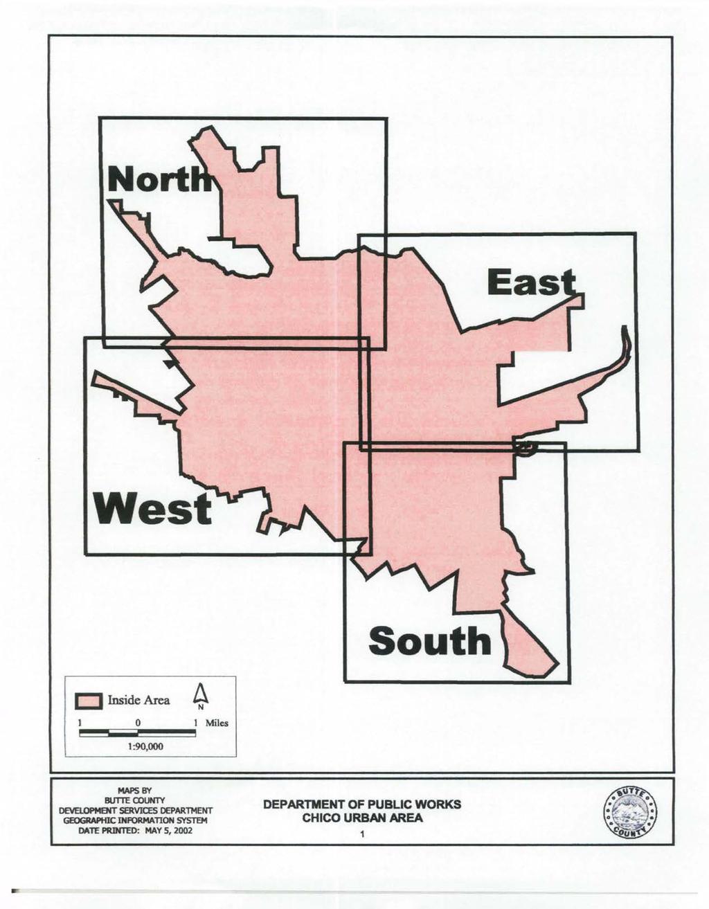
61
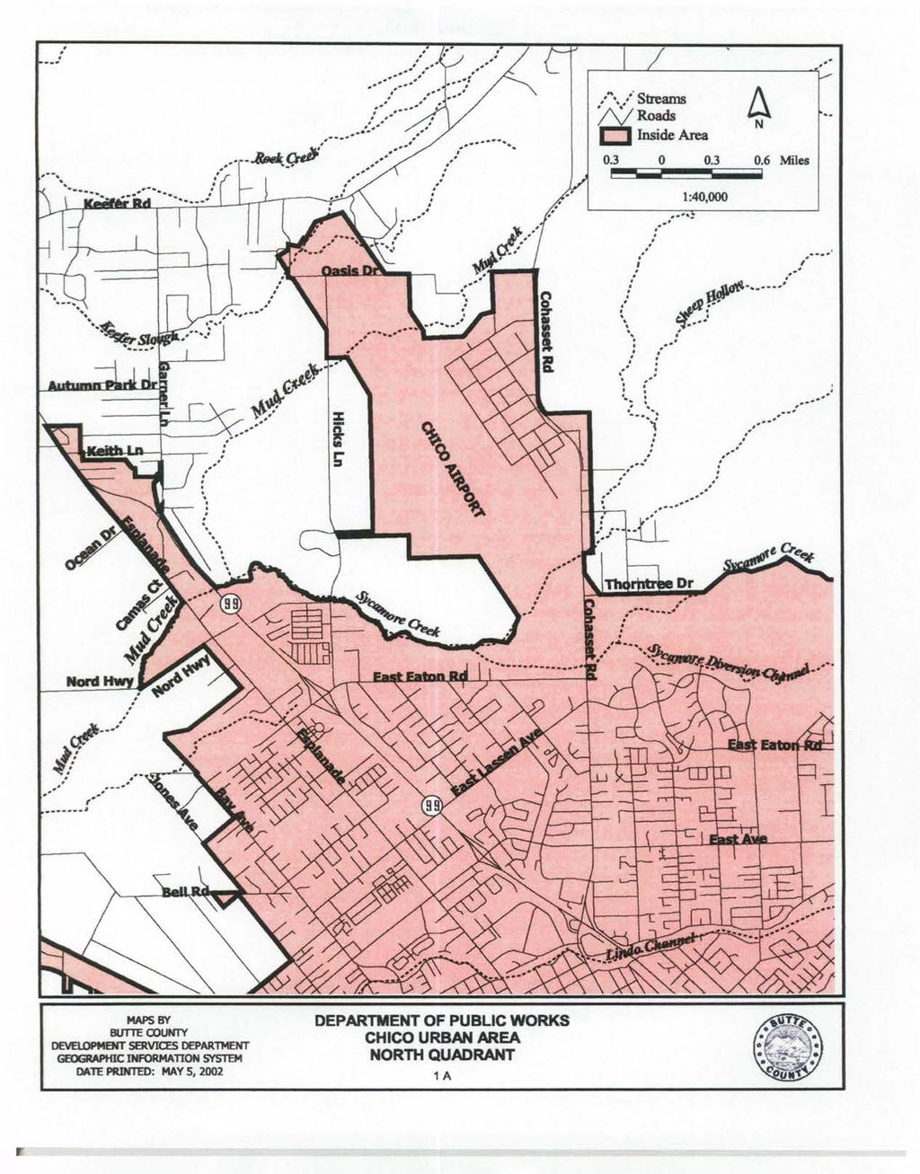
62
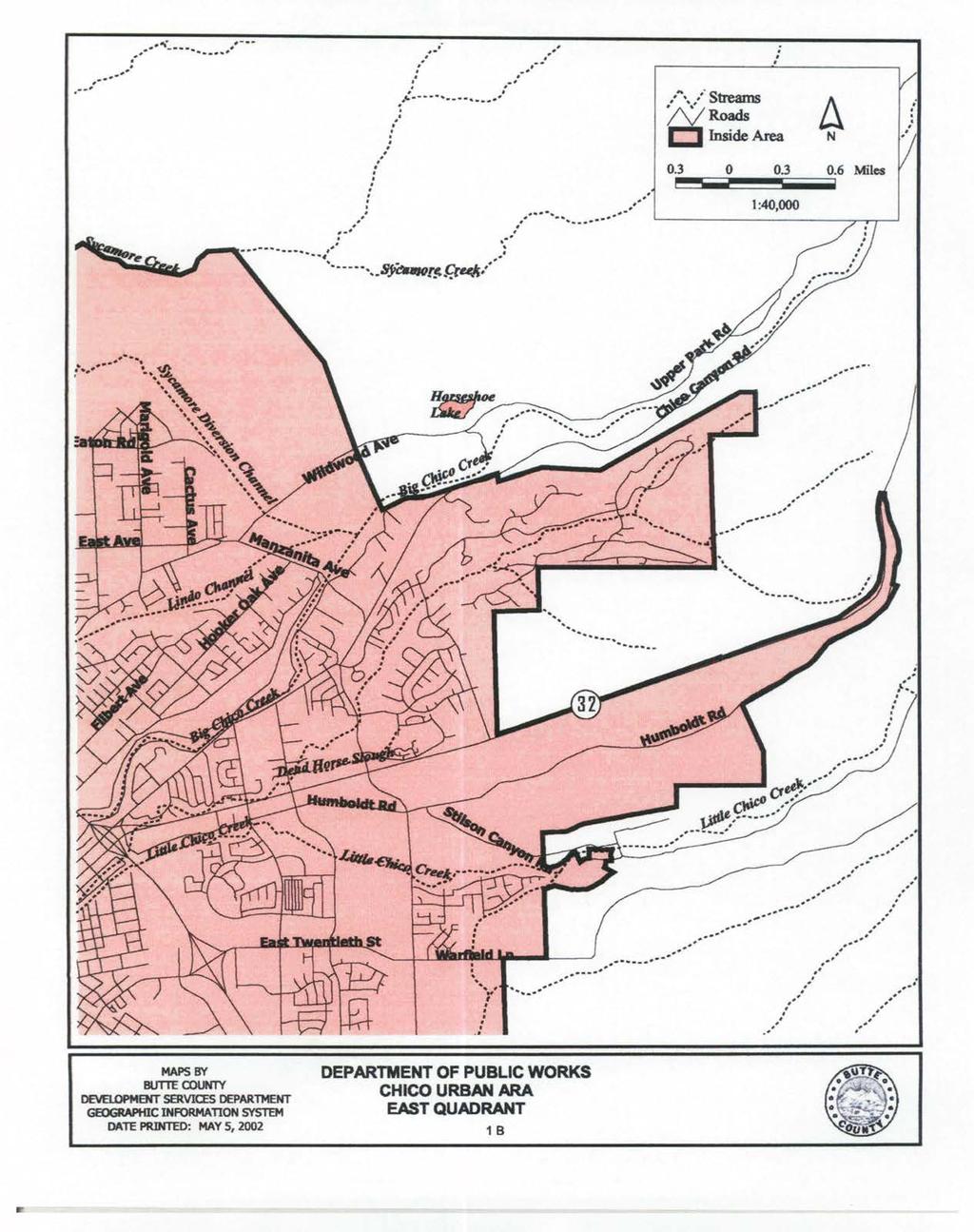
63
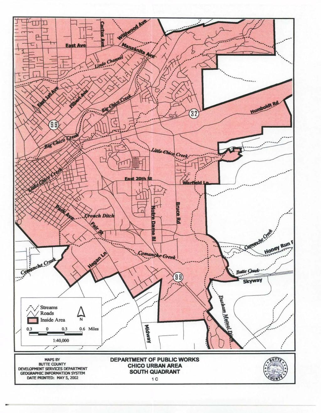
64
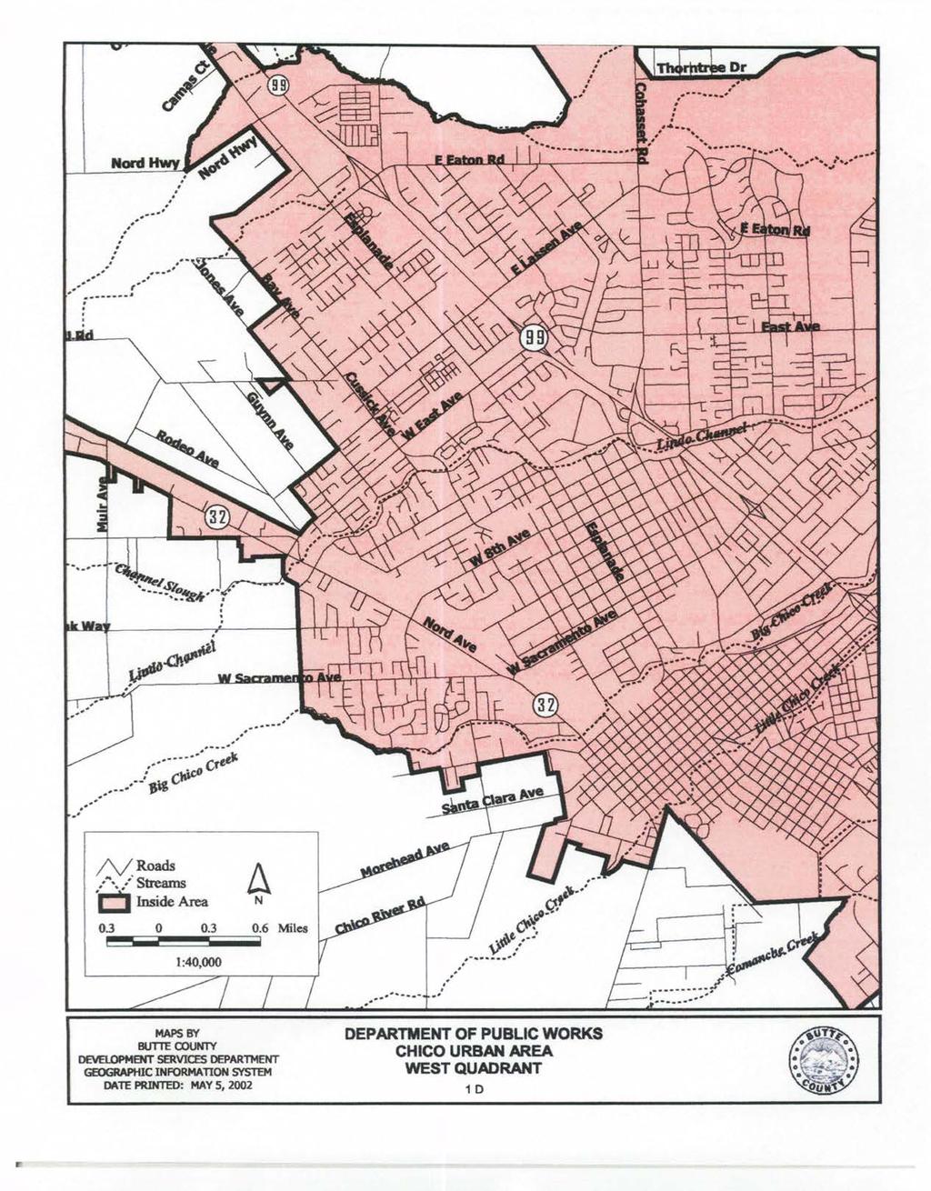
65
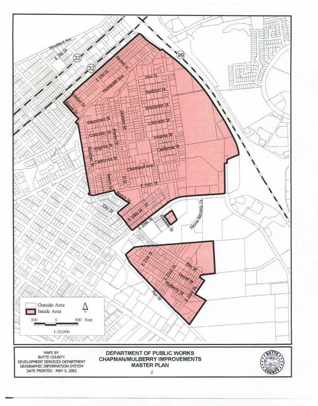
66
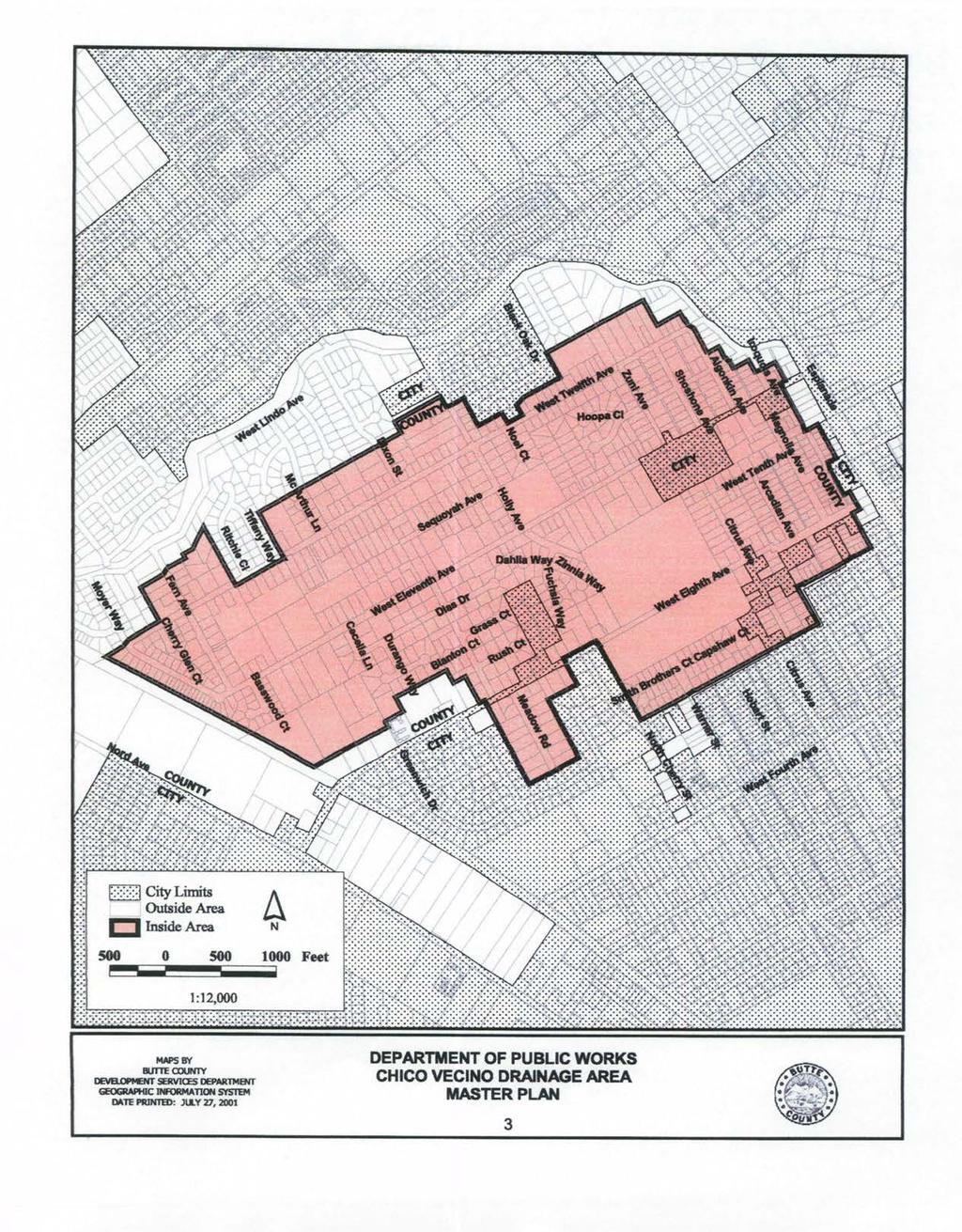
67

68
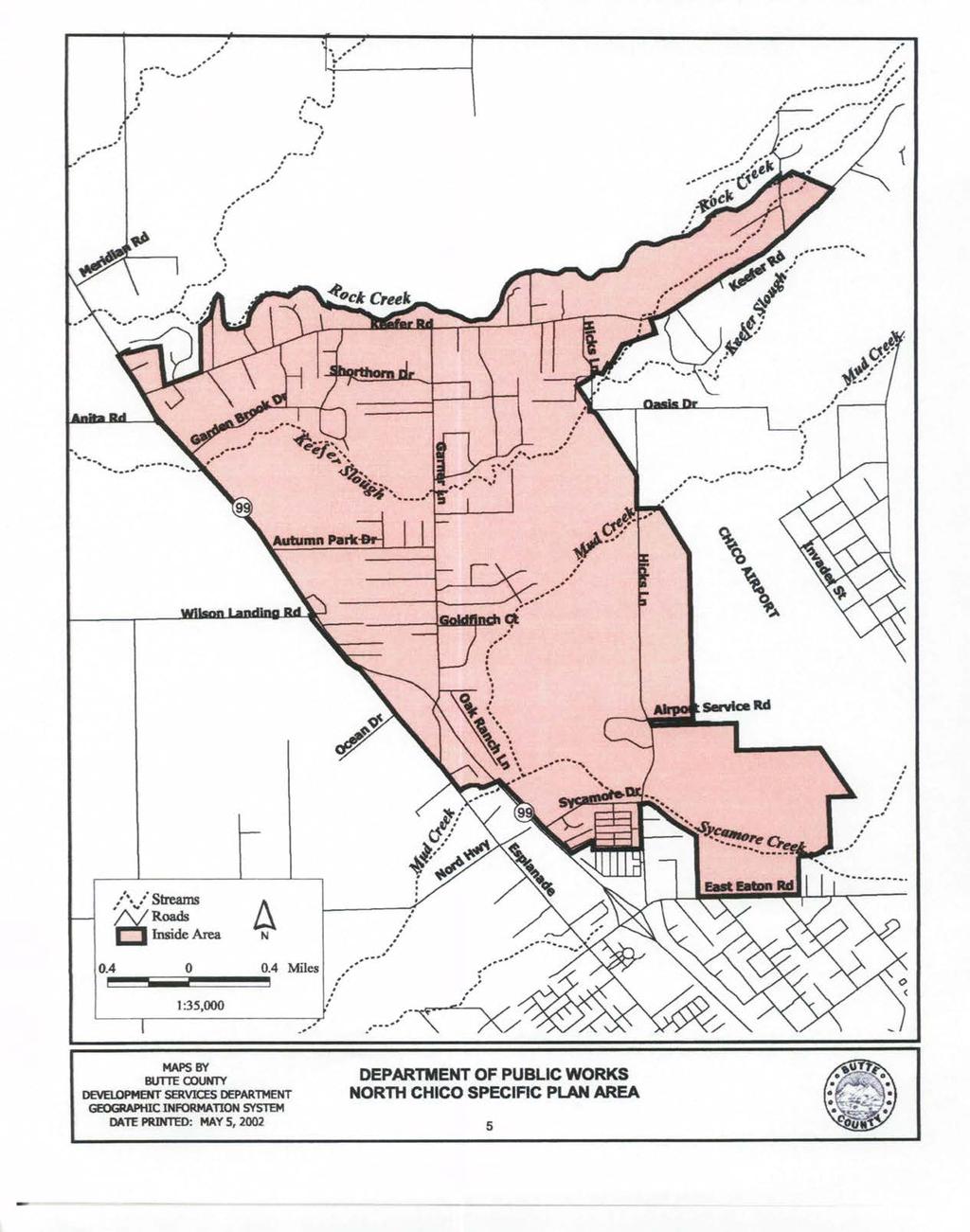
69
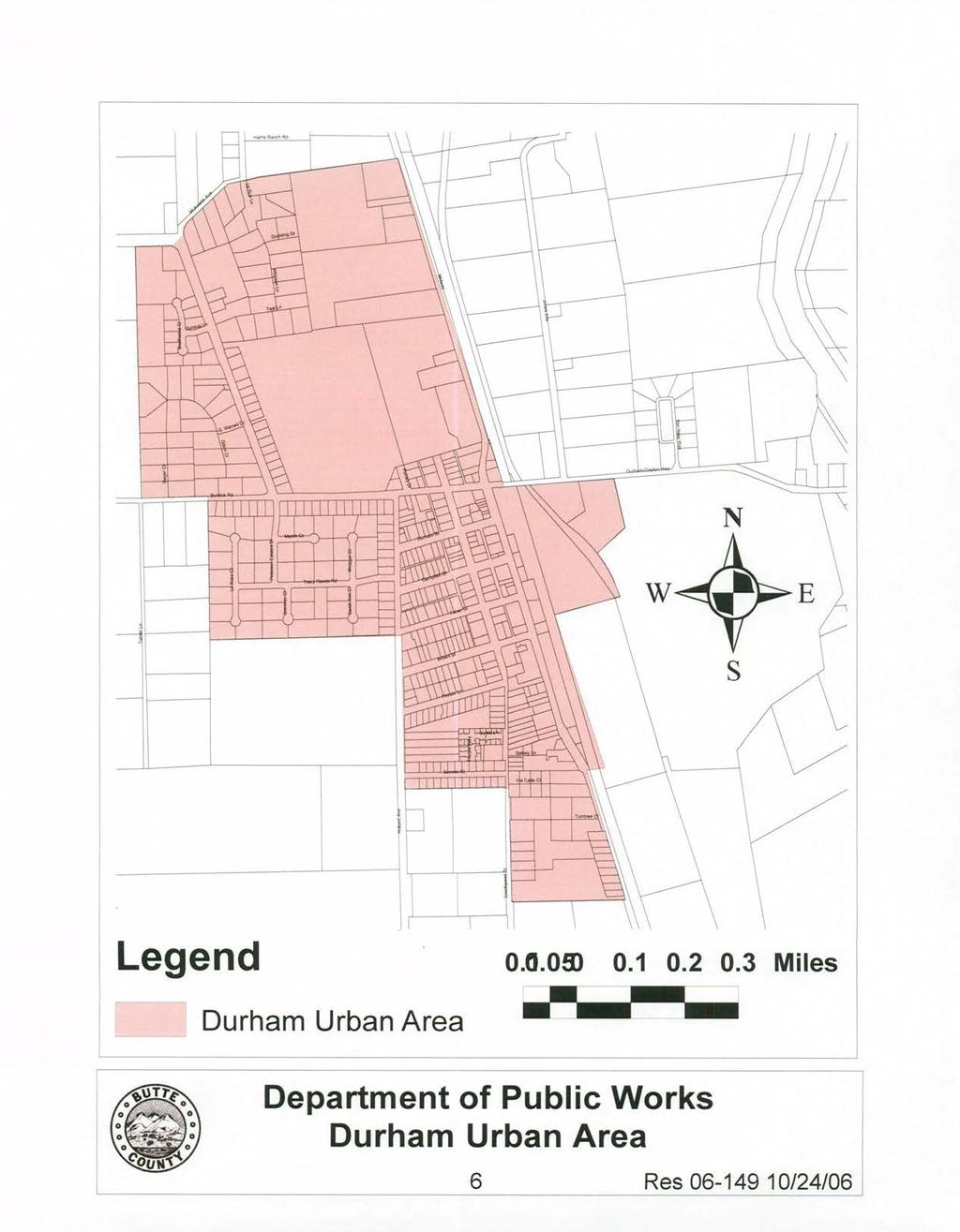
70
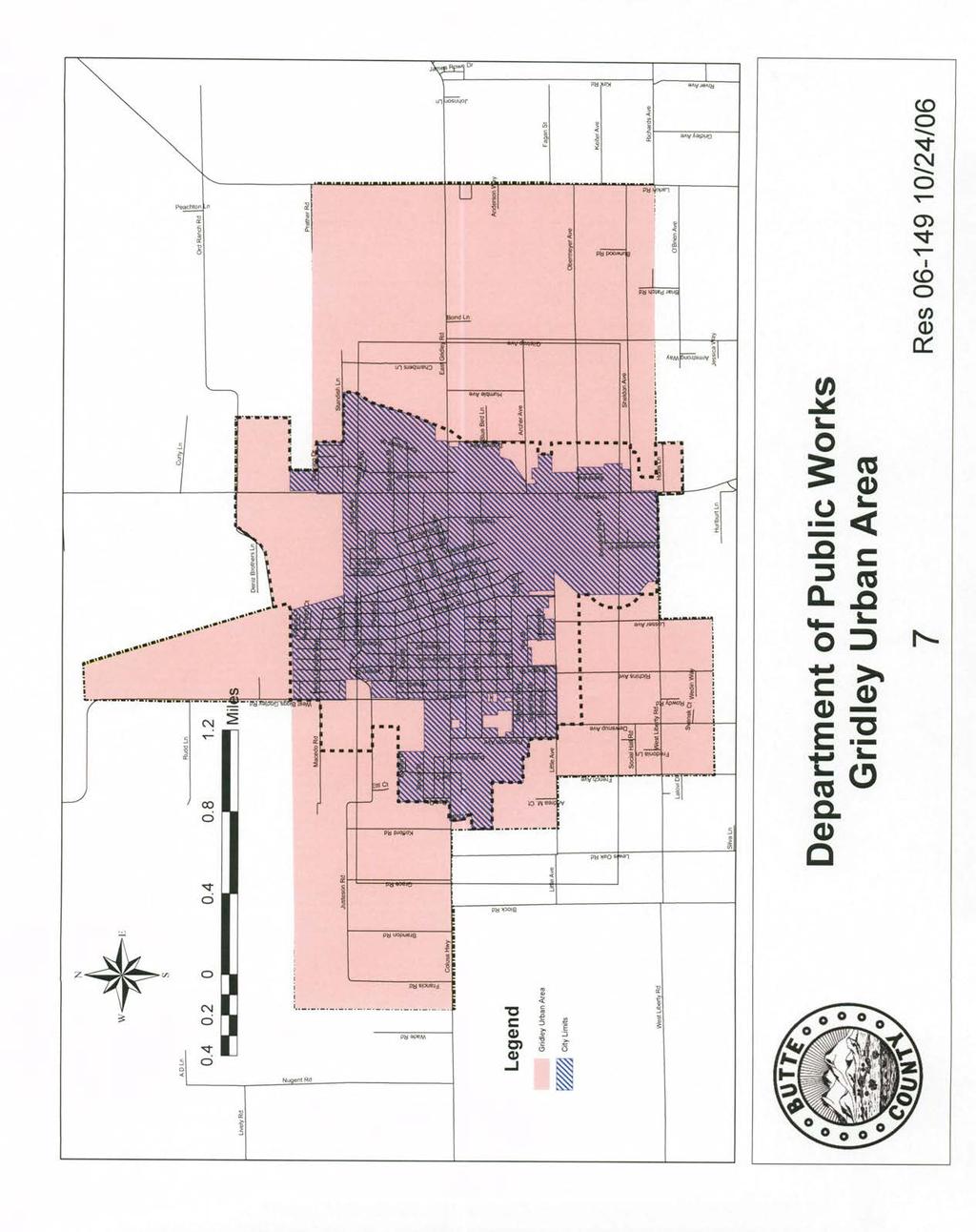
71
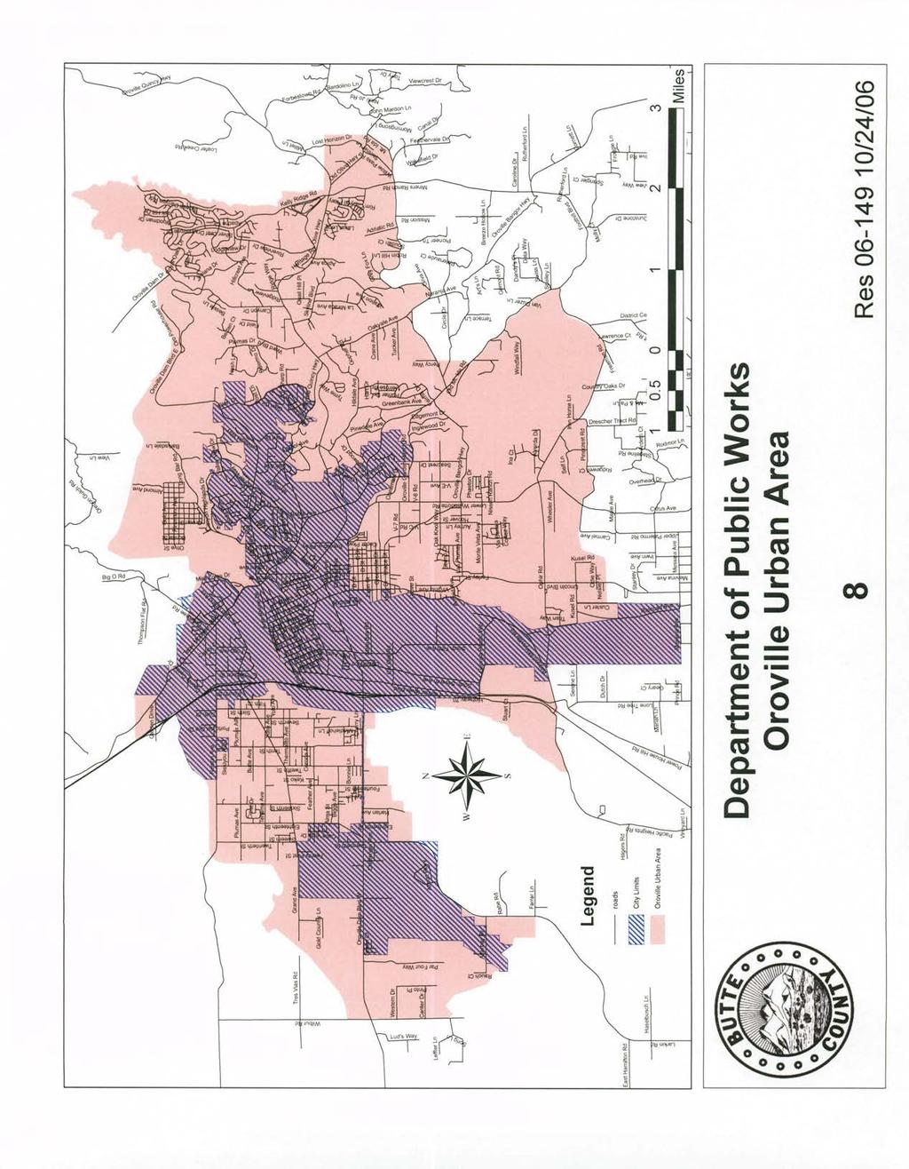
72
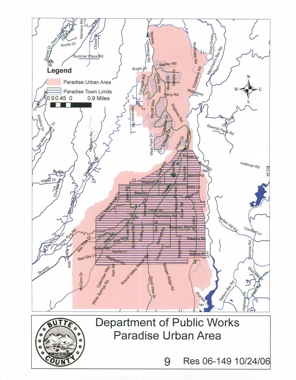
73
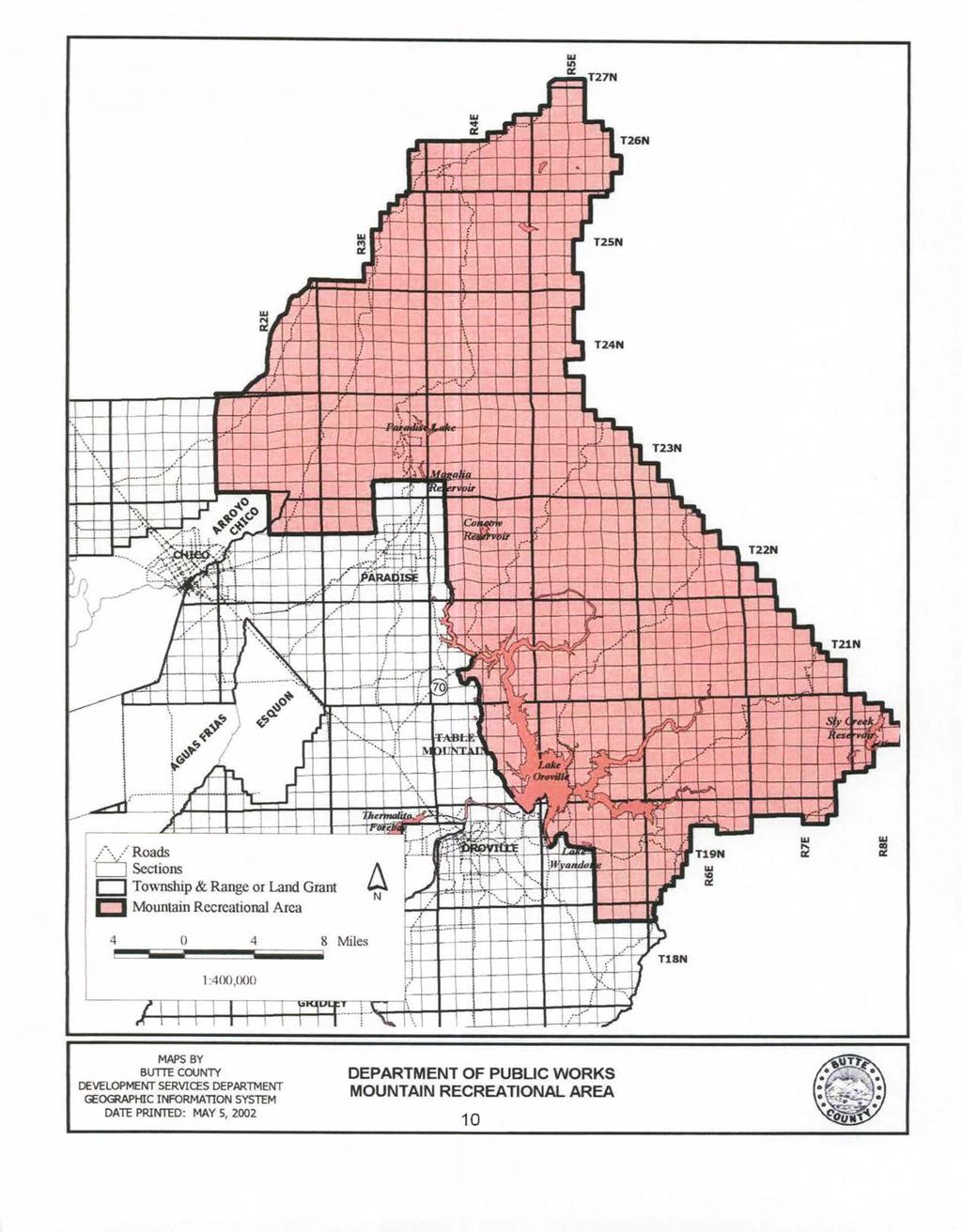
74
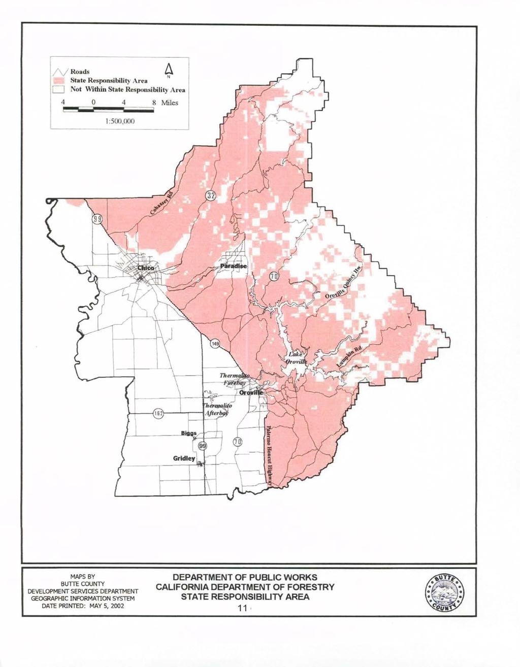
75
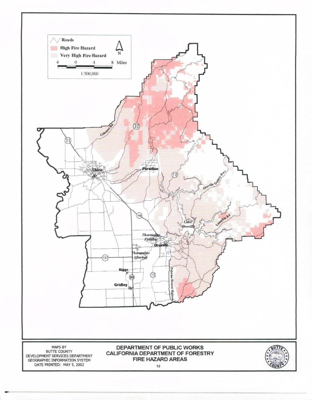
76
77 APPENDIX II SUBDIVISION ROAD STANDARDS Typical Section for Commercial and Industrial Subdivisions RS-1 Typical Road Sections for All Urban Land Divisions RS-2 Typical Road Sections for Rural Subdivisions RS-3 Typical Road Sections for Subdivisions within Mountain Recreation Area RS-4 Typical Section for Frontage Roads RS-5 Typical Section for Mountain Recreation Subdivision Private Road Improvement RS-6 Typical Section for Rural Subdivision Private Road Improvement RS-7 Typical Sections for Non-Urban Area Land Divisions RS-8-LD (I to IV) Typical Sections for Chapman/Mulberry Neighborhood Plan Northeast End Jackson Street (Wisconsin Street to End) CM-1 Typical Sections for Chapman/Mulberry Neighborhood Plan Davis Street, Martin Street, Madison Street, Wisconsin Street, Colorado Street, California Street, Jackson Street, B Street, Mulberry Street, Laurel Street, Fetter Street CM-2 Typical Sections for Chapman/Mulberry Neighborhood Plan East Tenth Street, Linden Street, Willow Street, Bartlett Street, Guill Street, Ohio Street, Elm Street, 21 st Street, 22 nd Street, 23rd Street CM-3 Typical Sections for Chapman/Mulberry Neighborhood Plan Humboldt Avenue CM-4 Typical Sections for Chapman/Mulberry Neighborhood Plan C Street, 16 th Street CM-5 Typical Sections for Chapman/Mulberry Neighborhood Plan Bruce Street CM-6 Typical Sections for Chapman/Mulberry Neighborhood Plan Virginia Street, Cleveland Street CM-7 Typical Sections for Chapman/Mulberry Neighborhood Plan Boucher Avenue CM-8 Arterial Type A-II Hicks Lane Eaton to Village Core NCSP-1 Arterial Type A-III New Arterial Hicks Lane to Mud Creek NCSP-2 Arterial Type A-IV New Arterial Mud Creek to Highway 99 Keefer Road Hicks Lane to Highway 99 Hicks Lane Eaton Road to Caballo Way Garner Lane Keefer Road to Highway 99 NCSP-3 Collector Type C-1 Village Core Collector NCSP-4 Collector Type C-1I Hicks Lane Keefer Road to Mud Creek NCSP-5 Local Type L-I Local Streets in M-1 & M-2 Zones NCSP-6 Local Type L-II Local Streets in R-1, R-2 & R-3 Zones NCSP-7 Local Type L-III Local Streets in SR-1 & SR-3 Zones NCSP-8 Local Type L-IV Cul-de-sac Streets in R-1, R-2 & R-3 Zones NCSP-9 Local Type L-V Cul-de-sac & Local Streets in SR-1 & SR-3 Zones NCSP-10 Local Type L-VI One Way Loop Street NCSP-11 Local Type L-VII Alleys in R-1 & R-2 Zones NCSP-12
78
79
80
81
82
83
84
85
86
87
88
89
90
91
92
93
94
95
96
97 APPENDIX III STANDARD DETAILS Typical Sections for: Vertical & Rolled Curb, Gutter and Sidewalk S-1 Typical Sections for Concrete: Vertical and Rolled Curb and Gutter S-2 Concrete Residential Driveway Approach S-3 Concrete Commercial Driveway Approach S-3A Cross Sections - Concrete Commercial Driveway Approach S-3B Standard Cross Gutter S-4 Concrete Pedestrian Ramp Type A S-5 Detectable Warning Surface S-5A Concrete Pedestrian Ramp Type B S-6 Typical Headwall Structural Details S-7 Type Go Drainage Inlet and Details S-8 Modified Type Go Drainage Inlet Side Opening S-8A Modified Type Go Drainage Inlet and Details Checker Plate S-8B Type Go Drainage Inlet and Details No Curb S-8C Type C Inlet S-9 Concrete Trench Cover for Streets and Sidewalks S-10 Street Survey Monument S-11 Standard Survey Control Monument S-11A County Road Sign S-12 Private Road Sign S-12A Street and Stop Sign Post Details County Right of Way S-13 Street Name Sign Post Details Private Road S-13A Temporary Cul-de-sac S-14 Permanent Cul-de-sac S-15 Offset Cul-de-sac S-15A Driveways for Rural Hillside Mountain Recreation Areas S-16 Typical Details of Pavement Replacement and Backfill Requirements S-17 Arterial Public Road Intersection S-18 Collector Public Road Connection S-18A Local Public Road Connection S-18B Standard Manhole S-19 Standard Drop Manhole S-20 Approved Methods of Laying Pipe S-21 Typical Method for Setting Appurtenances S-22 Standard Flushing Hole C.I. Frame and Cover S-23 Standard Manhole Frame and Cover Details S-24 Eccentric Manhole Details S-25 Eccentric Manhole for C-I-P-C-P S-26 Standard Fire Hydrant Installation S-27 Standard Fire Hydrants S-28 Swimming Pool and Water Tank Connection S-29 Guard Panel and Guard Post Details S-30 Private Driveway Details S-31 Concrete Private Driveway Behind Asphalt Dike Section S-31A Private Driveway Behind Asphalt Dike Section S-31B Cast-in-Place Concrete Pipe in Road or Street Right of Way S-32 Drainage Ditch Pipe Outlet Details S-33
98 Sacked Concrete Slope Protection with Storm Drain Installation into Channels S-34 Utility Trench Details S-35 Fences, Walls and Hedges Cornet Lot S-36 Fences, Walls and Hedges Interior Lot S-37 Typical Storm Drainage Leach Trench S-38 Typical Inlet to Leach Trench Connection S-39 Storm Water Management Program Drainage Inlet Marker S-40 Bicycle/Pedestrian Path Traffic Barrier Post S-41 Building Free Turn Around Area (Hammer Head T) S Speed Hump S-43 Speed Table S-44
99
100
101
102
103
104
105
106
107
108
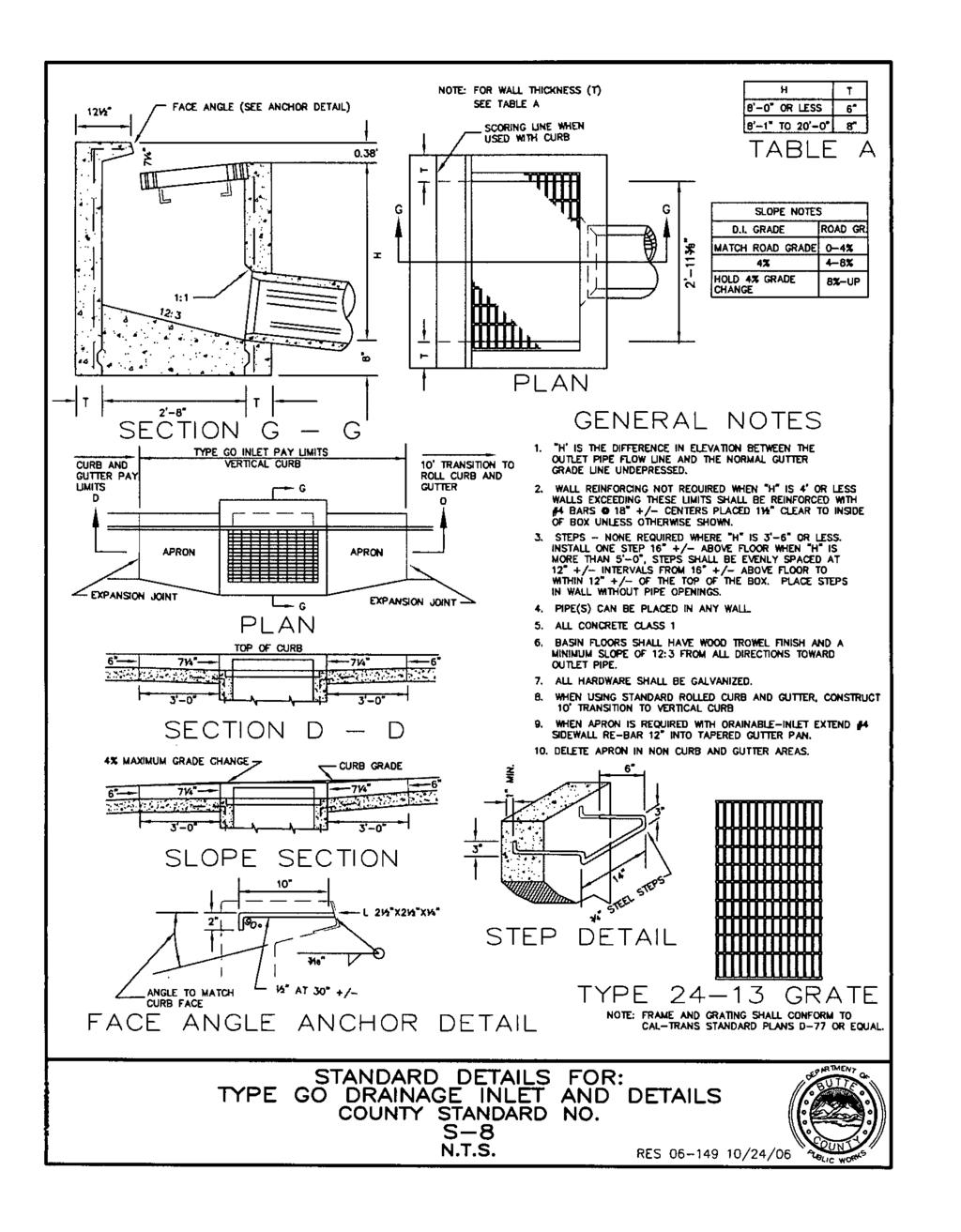
109
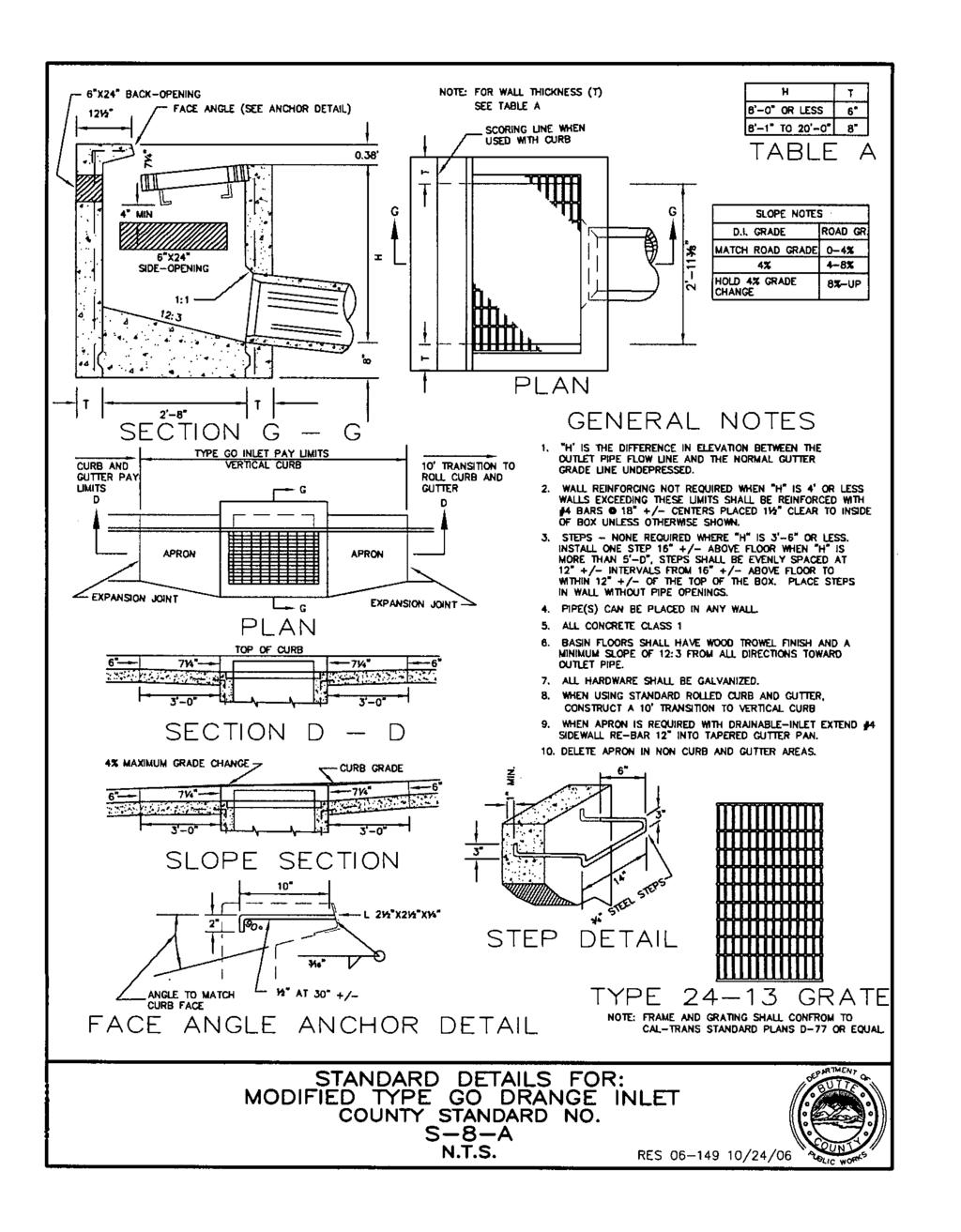
110
111
112
113
114
115
116
117
118
119
120
121
122
123
124
125
126
127
128
129
130
131
132
133
134
135
136
137
138
139
140
141
142
143
144
145
146
147
148
149
150
151
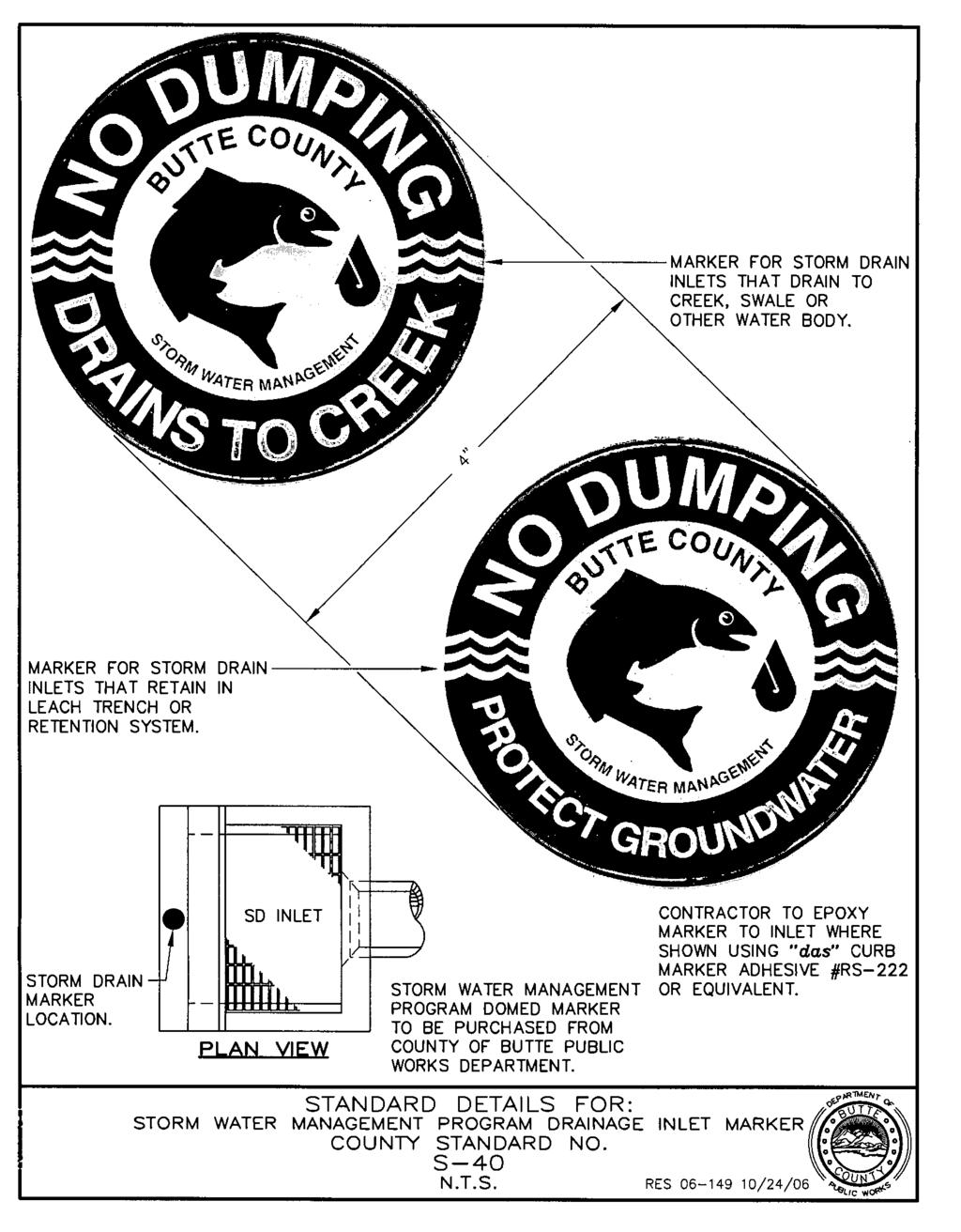
152
COUNTY OF YUBA DEPARTMENT OF PUBLIC WORKS IMPROVEMENT STANDARDS
 COUNTY OF YUBA DEPARTMENT OF PUBLIC WORKS IMPROVEMENT STANDARDS TABLE OF CONTENTS SECTION 1 PURPOSE AND DEFINITIONS 1.1 PURPOSE:... 1 1.2 DEFINITIONS:... 1 SECTION 2 GENERAL REQUIREMENTS 2.1 PLANS BY AN
CITY OF JACKSON IMPROVEMENT STANDARDS RESOLUTION NO.
 CITY OF JACKSON IMPROVEMENT STANDARDS RESOLUTION NO. April 2012 TABLE OF CONTENTS 1.00 PURPOSE AND INTENT... 1 2.00 GENERAL REQUIREMENTS... 3 2.01 PLANS AND SPECIFICATIONS REQUIRED... 3 2.02 STANDARD SPECIFICATIONS...
SECTION CONSTRUCTION SERVICES
 SECTION 01100 CONSTRUCTION SERVICES PART 1 GENERAL 1.01 - Section Includes A. Mobilization. B. Construction Surveys. C. Record Documents. 1.02 Description Of Work A. Mobilization: includes the preparatory
CONSTRUCTION SURVEY. Construction survey includes personnel, equipment, and supplies required for, but not limited to, the following:
 CONSTRUCTION SURVEY PART 1 - GENERAL 1.01 SECTION INCLUDES Construction survey includes personnel, equipment, and supplies required for, but not limited to, the following: A. Construction Survey: 1. Project
CONSTRUCTION STAKING GUIDELINES
 CITY OF LOS ANGELES DEPARTMENT OF PUBLIC WORKS BUREAU OF ENGINEERING SURVEY DIVISION CONSTRUCTION STAKING GUIDELINES Gary Lee Moore, P.E., City Engineer Tony Pratt, Chief Surveyor TABLE OF CONTENTS Dec.
CUYAHOGA COUNTY DEPARTMENT OF PUBLIC WORKS CUYAHOGA COUNTY ENGINEER TOWNSHIP SUBDIVISION STREET DESIGN STANDARDS AND IMPROVEMENT PLAN REQUIREMENTS
 CUYAHOGA COUNTY DEPARTMENT OF PUBLIC WORKS CUYAHOGA COUNTY ENGINEER TOWNSHIP SUBDIVISION STREET DESIGN STANDARDS AND IMPROVEMENT PLAN REQUIREMENTS November 25, 2013 Table of Contents Cuyahoga County Engineer's
CONSTRUCTION PLAN CHECKLIST
 CONSTRUCTION PLAN CHECKLIST The design engineer is responsible for ensuring that plans submitted for city review are in accordance with this checklist. It is requested that the executed checklist be submitted
STREET IMPROVEMENTS (Refer to Title 18, chapter entitled "STREETS" of the Layton Municipal Code.)
") STREET IMPROVEMENTS (Refer to Title 18, chapter 18.24 entitled "STREETS" of the Layton Municipal Code.) I. Street widths STREET TYPE (ALL MEASUREMENTS IN FEET) ROW WIDTH LAYTON CITY STANDARD STREET SECTIONS
STREET IMPROVEMENTS (Refer to Title 18, chapter 18.24 entitled "STREETS" of the Layton Municipal Code.) I. Street widths STREET TYPE (ALL MEASUREMENTS IN FEET) ROW WIDTH LAYTON CITY STANDARD STREET SECTIONS
PLANNING AND ZONING COMMISSION APPLICATION FOR IMPROVEMENT PLAT APPROVAL
 PLANNING AND ZONING COMMISSION APPLICATION FOR IMPROVEMENT PLAT APPROVAL Date Submitted: Project Number: CITY OF ALEXANDRIA 8236 WEST MAIN STREET ALEXANDRIA, KY 41001 (859) 635-4125 FAX (859) 635-4127
Zoning Permits 11-1 ZONING PERMITS
 Zoning Permits 11-1 ZONING PERMITS (a) Building or structures shall be started, repaired, reconstructed, enlarged or altered only after a zoning permit has been obtained from the administrator and a building
TOWN OF MANCHESTER PLANNING AND ZONING COMMISSION Subdivision Application Minimum Submission Requirements
 TOWN OF MANCHESTER PLANNING AND ZONING COMMISSION Subdivision Application Minimum Submission Requirements This checklist is to be completed and submitted with all Subdivision Applications. The Town reserves
Chapter 3: Permit Procedures and Requirements
 Chapter 1: General Provisions 1 1 Short Title 1 2 Jurisdiction 1 3 Amendments and Revisions 1 4 Enforcement Responsibility 1 5 Review Process 1 6 Prior Approval 1 7 Relationship to Other Standards 1 8
GRAYSON COUNTY POLICY, PROCEDURES AND SPECIFICATIONS OF GRAYSON COUNTY, TEXAS FOR THE INSTALLATION OF DRIVEWAY
 GRAYSON COUNTY POLICY, PROCEDURES AND SPECIFICATIONS OF GRAYSON COUNTY, TEXAS FOR THE INSTALLATION OF DRIVEWAY CULVERTS, ROAD BORES, USE OF HEAVY EQUIPMENT AND UTILITY LINES WITHIN GRAYSON COUNTY ROAD
CITY OF ASTORIA PUBLIC WORKS ENGINEERING DIVISION ENGINEERING DESIGN STANDARDS FOR IN-FILL DEVELOPMENT
 CITY OF ASTORIA PUBLIC WORKS ENGINEERING DIVISION ENGINEERING DESIGN STANDARDS FOR IN-FILL DEVELOPMENT Adopted by City Council: May 21, 2007 X:\General Eng\DESIGN STANDARDS\Engineering Design Standards
Section 7 Roadway GENERAL REQUIREMENTS I. TYPICAL SECTION...7-1
 Section 7 Roadway GENERAL REQUIREMENTS...7-1 I. TYPICAL SECTION...7-1 7.1 LANE WIDTHS...7-1 7.2 SHOULDER WIDTHS...7-1 7.3 CROSS SLOPE...7-2 7.4 CURB AND UNDERDRAINS...7-2 7.5 SIDEWALKS AND DRIVEWAYS...7-2
T a b l e o f C o n t e n t s
 C i t y o f G l a d s t o n e P u b l i c W o r k s D e s i g n S t a n d a r d s T a b l e o f C o n t e n t s SECTION THREE SANITARY SEWER REQUIREMENTS... 1 3.0000 SANITARY SEWERS... 1 3.0010 General
SECTION 12 STANDARDS FOR CONSTRUCTION PLANS AND SPECIFICATIONS
 SECTION 12 STANDARDS FOR CONSTRUCTION PLANS AND SPECIFICATIONS 12.1 The subdivider shall construct and install the improvements in accordance with the County's Standards for Construction Plans and Specifications
CONSTRUCTION PLAN REVIEW CHECKLIST FOR PRIVATE DEVELOPMENT
 ADDITION NAME: City of Grapevine, Texas CONSTRUCTION PLAN REVIEW CHECKLIST FOR PRIVATE DEVELOPMENT Updated April 16, 2018 Public Works Department Engineering Division 200 South Main Street Grapevine, Texas
CITY OF LA QUINTA GENERAL NOTES GENERAL NOTES
 CITY OF LA QUINTA GENERAL NOTES GENERAL NOTES 1. ALL WORK SHALL BE DONE IN ACCORDANCE WITH THE LATEST EDITION OF THE STANDARD PLANS OF THE CITY OF LA QUINTA, THE LATEST EDITION OF THE STANDARD SPECIFICATIONS
MONTEZUMA COUNTY COLORADO ROAD AND BRIDGE STANDARD SPECIFICATIONS
 MONTEZUMA COUNTY COLORADO ROAD AND BRIDGE STANDARD SPECIFICATIONS The following Standard Specifications for Road and Bridge Construction in Montezuma County, Colorado have been amended this 22 nd, day
SUBDIVISION CHECKLIST. Subdivision Name. Prior To Review. Preliminary plan approved by Planning Commission / Council as required.
 SUBDIVISION CHECKLIST Subdivision Name Account Number Review Engineer Prior To Review Preliminary plan approved by Planning Commission / Council as required. Review fee paid. Statement of Responsibility
PART II. - SPECIFICATIONS AND DESIGN STANDARDS TO CITY OF HEWITT, TEXAS SUBDIVISION ORDINANCE FOR PUBLIC WORKS CONSTRUCTION [TEXT]
![PART II. - SPECIFICATIONS AND DESIGN STANDARDS TO CITY OF HEWITT, TEXAS SUBDIVISION ORDINANCE FOR PUBLIC WORKS CONSTRUCTION [TEXT]](/thumbs/80/81891816.jpg "PART II. - SPECIFICATIONS AND DESIGN STANDARDS TO CITY OF HEWITT, TEXAS SUBDIVISION ORDINANCE FOR PUBLIC WORKS CONSTRUCTION [TEXT]") PART II. - SPECIFICATIONS AND DESIGN STANDARDS TO CITY OF HEWITT, TEXAS SUBDIVISION ORDINANCE FOR PUBLIC WORKS CONSTRUCTION [TEXT] A. - General. B. - Streets. C. - Stormwater drainage system. D. - Water
PART II. - SPECIFICATIONS AND DESIGN STANDARDS TO CITY OF HEWITT, TEXAS SUBDIVISION ORDINANCE FOR PUBLIC WORKS CONSTRUCTION [TEXT] A. - General. B. - Streets. C. - Stormwater drainage system. D. - Water
GRADING & DRAINAGE PERMIT SOIL EROSION AND SEDIMENTATION CONTROL PERMIT PROGRAM OVERVIEW
 GRADING & DRAINAGE PERMIT SOIL EROSION AND SEDIMENTATION CONTROL PERMIT PROGRAM OVERVIEW Chapter 8 Building and Building Regulations, Article XIII Grading and Drainage and Article XV Soil Erosion and Sedimentation
ROADWAY DESIGN AND CONSTRUCTION STANDARDS
 ROADWAY DESIGN AND CONSTRUCTION STANDARDS Adopted: 1990 Amended: 1994 2003 2011 2013 ROADWAY DESIGN AND CONSTRUCTION STANDARDS ORIGINALLY ADOPTED IN 1990 Resolution No. R-990-046 OFFICIALLY AMENDED IN
APPENDIX A DESIGN SPECIFICATIONS FOR NEW ROAD CONSTRUCTION
 APPENDIX A DESIGN SPECIFICATIONS FOR NEW ROAD CONSTRUCTION 1. GENERAL SPECIFICATIONS 1.1 Specifications: Plans shall be prepared by a professionally registered engineer duly authorized to conduct business
CHAPTER 70 PUBLIC WORKS DEPARTMENT DEVELOPMENT STANDARDS ARTICLE 70 BASIC PROVISIONS
 CHAPTER 70 PUBLIC WORKS DEPARTMENT DEVELOPMENT STANDARDS ARTICLE 70 BASIC PROVISIONS 70.010 - PURPOSE The purpose of this chapter is to establish standards for the design and development of sites in order
SECTION 14 EMBANKMENT
 SECTION 14 EMBANKMENT 14.1 DESCRIPTION A. General: This work consists of constructing roadway embankments, including preparation of the areas upon which embankments are to be placed; the construction of
Ordinance No Lot Surface Drainage
 Ordinance No. 35-2008 - Lot Surface Drainage The Township has adopted a new Lot Surface Drainage Ordinance which amends Chapter 170, Article IX, Subdivision and Site Plan Review by adding a new Section
CHAPTER 5 WATER SYSTEM DESIGN STANDARDS
 CHAPTER 5 WATER SYSTEM DESIGN STANDARDS TABLE OF CONTENTS CHAPTER 5 WATER SYSTEM DESIGN STANDARDS 5.00 Objective Page 1 5.01 Additional Referenced Standards Page 1 5.02 Special Design Problems Page 2 5.03
IMPROVEMENT STANDARDS
 VALLEY SPRINGS PUBLIC UTILITY DISTRICT IMPROVEMENT STANDARDS WATER ***** WASTEWATER Valley Springs Public Utility District PO Box 284 Valley Springs, California 95252 SEPTEMBER 2013 VALLEY SPRINGS PUBLIC
Appendix 3. POLICY & PROCEDURE No
 DEPARTMENT OF PUBLIC WORKS DIVISION: ENGINEERING SERVICES SECTION: ADMINISTRATIVE PAGE NO: 1 OF 10 REVISION NO: 3 DATE: 1995 05 01 ESTABLISHED: 1986 03 03 Appendix 3 POLICY & PROCEDURE No. 2.3.1-020 TITLE:
ARTICLE XII RECREATIONAL VEHICLE PARK REGULATIONS
 ARTICLE XII RECREATIONAL VEHICLE PARK REGULATIONS ARTICLE XII RECREATIONAL VEHICLE PARK REGULATIONS Section 1201 Applicability For the purpose of this Article, recreation vehicles and recreational vehicle
UNIFORM DESIGN AND CONSTRUCTION STANDARDS FOR EXTENDING WATER DISTRIBUTION SYSTEMS SECTION 2 DESIGN STANDARDS
 UNIFORM DESIGN AND CONSTRUCTION STANDARDS FOR EXTENDING WATER DISTRIBUTION SYSTEMS SECTION 2 DESIGN STANDARDS DESIGN STANDARDS SECTION 2 INDEX ITEM DESCRIPTION 2.00 GENERAL STATEMENT 2.01 WATER DISTRIBUTION
ARTICLE 700 LARGE SCALE DEVELOPMENTS
 ARTICLE 700 LARGE SCALE DEVELOPMENTS SEC. 700.1 APPLICABILITY A development plan shall be submitted to the Bentonville Planning Commission for all developments or building construction regardless of zone
SECTION 6. ROAD CONSTRUCTION STANDARDS
 SECTION 6. ROAD CONSTRUCTION STANDARDS Construction of new roads or reconstruction of existing roads proposed for dedication to the County shall conform to the standards set forth in this section. Roads
SPECIFICATIONS FOR STREET CONSTRUCTION WITHIN THE TOWN OF PLAINVILLE
 SPECIFICATIONS FOR STREET CONSTRUCTION WITHIN THE TOWN OF PLAINVILLE BE IT ORDAINED by the Town Council of the Town of Plainville: SECTION 1. SUBDIVISIONS. All subdivisions hereinafter developed within
SECTION GENERAL EXCAVATION
 02210-1 of 11 SECTION 02210 GENERAL EXCAVATION 02210.01 GENERAL A. Description 1. General excavation shall include but not necessarily be limited to, excavation and grading for general site work, roadways,
PUBLIC WORKS DEPARTMENT GENERAL NOTES
 PUBLIC WORKS DEPARTMENT GENERAL NOTES 1. All construction shall be in strict accordance with the standards of the City of Southlake and governed by the North Central Texas Council of Government's Standard
ZONING ORDINANCE FOR THE ZONED UNINCORPORATED AREAS ARTICLE 1500 OF PUTNAM COUNTY, WEST VIRGINIA Page 149 ARTICLE 1500 DRAINAGE AND STORM SEWERS
 OF PUTNAM COUNTY, WEST VIRGINIA Page 149 ARTICLE 1500 DRAINAGE AND STORM SEWERS 1500.01 GENERAL REQUIREMENTS 1500.02 NATURE OF STORM WATER FACILITIES 1500.03 DRAINAGE EASEMENTS 1500.04 STORM WATER MANAGEMENT
SECTION 4 - DESIGN STANDARDS FOR WATER DISTRIBUTION FACILITIES
 SECTION 4 - DESIGN STANDARDS FOR WATER DISTRIBUTION FACILITIES 4.1 GENERAL REQUIREMENTS 4.1.1 Water and fire protection distribution facilities are to be provided solely for the purpose of supplying potable
APPLICATION FOR PUBLIC INFRASTRUCTURE PERMIT
 APPLICATION FOR PUBLIC INFRASTRUCTURE PERMIT Engineering Division 550 Landa Street New Braunfels, Texas 78130 (830) 221-4020 1. Subdivision Plat Name: Location Description/ Nearest Intersection: Acreage:
Plan Name Plan No. Submitting Firm Contact Engineer. Review Date ESI Team ENGINEERS AND SURVEYORS INSTITUTE PEER REVIEW CHECKLIST CITY OF ALEXANDRIA
 EROSION AND SEDIMENT CONTROL CHECKLIST (E&S) VIRGINIA EROSION AND SEDIMENT CONTROL HANDBOOK (1 of 2) Item # Description OK NO N/A 1 Limits of clearing and grading match on all appropriate sheets 2 Construction
GENERAL NOTES REQUIRED NOTES ON ALL PLANS
 GENERAL NOTES REQUIRED NOTES ON ALL PLANS ALL MATERIALS, WORKMANSHIP AND CONSTRUCTION SHALL CONFORM TO THE CURRENT CITY OF SANTA ROSA DESIGN AND CONSTRICTIOIN STANDARDS AND CONSTRUCTION SPECIFICATIONS
SECTION 13 - EXISTING FACILITIES TABLE OF CONTENTS
 SECTION 13 - EXISTING FACILITIES TABLE OF CONTENTS Section Page 13-1 GENERAL... 13.1 13-1.01 Preservation of Property... 13.1 13-1.02 Overloading, Pavement Protection & Repair... 13.1 13-2 REMOVING EXISTING
Recommended Technical Standards for Existing Roads UNH Technology Transfer Center
 Recommended Technical Standards for Existing Roads UNH Technology Transfer Center Purposes and Acknowledgements These model standards provide New Hampshire cities and towns with a set of recommendations
I. STREET CONSTRUCTION AND RECONSTRUCTION
 CITY OF OSHKOSH POLICY FOR SPECIAL ASSESSMENTS A. GENERAL I. STREET CONSTRUCTION AND RECONSTRUCTION 1. Assessments shall be levied according to the front foot dimensions of the abutting property to the
(ITEMS APPLICABLE TO THIS PROJECT MARKED WITH "X")
") Development Services Planning Division 150 N. Lakeshore Drive Ocoee, FL 34761 Phone: 407.905.3157 Fax: 407.905.3158 Received Date Office Use Only (ITEMS APPLICABLE TO THIS PROJECT MARKED WITH "X") DATE:
Development Services Planning Division 150 N. Lakeshore Drive Ocoee, FL 34761 Phone: 407.905.3157 Fax: 407.905.3158 Received Date Office Use Only (ITEMS APPLICABLE TO THIS PROJECT MARKED WITH "X") DATE:
Project: Developer/Designer: Reviewer:
 City of Charlottesville, Virginia Engineering Plan Review Checklist (Site Plans, Site Plan Amendments, and Major Subdivisions) 610 East Market Street, Charlottesville, VA 22902 Telephone 434-970-3182;
A.1 WATER SYSTEM PLAN SUBMITTAL PROCEDURES AND GENERAL REQUIREMENTS
 PC Plan Submittal and Review A.1 WATER SYSTEM PLAN SUBMITTAL PROCEDURES AND GENERAL REQUIREMENTS All plans for water main extensions, improvements and modifications shall be submitted to the District manager.
CITY OF BENICIA IMPROVEMENT PLAN REVIEW CHECKLIST
 CITY OF BENICIA DEPARTMENT OF PUBLIC WORKS ENGINEERING DIVISION 250 EAST L STREET, BENICIA, CA 94510 Phone: (707) 746-4240 CITY OF BENICIA IMPROVEMENT PLAN REVIEW CHECKLIST Tract Map # This checklist is
This is only a general checklist; please refer to the CVWD Development Design Manual (DDM) for all requirements and regulations.
 for all requirements and regulations.") COACHELLA VALLEY WATER DISTRICT DOMESTIC WATER CHECKLIST Tract/Parcel No: Project Common Name: Developer: Engineer: Engineer Signature: Date: Phone: Phone: Print: This is only a general checklist; please
COACHELLA VALLEY WATER DISTRICT DOMESTIC WATER CHECKLIST Tract/Parcel No: Project Common Name: Developer: Engineer: Engineer Signature: Date: Phone: Phone: Print: This is only a general checklist; please
City of Elgin SUBDIVISION FINAL ENGINEERING Engineering Submittal Checklist
 If this is a re-submittal, please provide a point-by-point response to previous review comments, identifying how each comment has been addressed, location in the plan set of the changes made to address
INSPECTION AND ACCEPTANCE FOR MAINTENANCE
 Inspection and Acceptance For Maintenance Page 1 (Last revised 6/29/10) INSPECTION AND ACCEPTANCE FOR MAINTENANCE SELECTED LINKS TO SECTIONS WITHIN THIS SPECIFICATION Acceptance Sewer As Built Drwg Example
STANDARD GRADING AND SOIL EROSION & SEDIMENT CONTROL PLAN FOR SINGLE LOT SINGLE FAMILY RESIDENTIAL CONSTRUCTION AND MINOR EARTH DISTURBANCES
 DIVISION OF ENGINEERING & CONSTRUCTION MANAGEMENT PLAN REVIEW DEPARTMENT WASHINGTON COUNTY SOIL CONSERVATION DISTRICT 1260 Maryland Avenue, Suite 101 Hagerstown, MD 21740 Telephone: (301) 797-6821, Ext.
1.01 GENERAL. l.02 PIPELINE TRENCH EXCAVATION PIPELINES AND STRUCTURES REVISION: SECTION 1 PAGE : 1-1
 1.01 GENERAL A. The Contractor shall perform all excavation, backfilling, grubbing and grading required for construction and installation of pipelines, structures and appurtenances. Excavation shall include
20 North Main Alpine, UT (Phone) (Fax) SITE PLAN
 (Fax) SITE PLAN") Site Plan Instructions New Home Form #1 20 North Main Alpine, UT 84004 801-756-6347 (Phone) 801-756-1189 (Fax) www.alpinecity.org SITE PLAN A detailed site plan, drawn to scale, 1 = 20 min., shall be filed
Site Plan Instructions New Home Form #1 20 North Main Alpine, UT 84004 801-756-6347 (Phone) 801-756-1189 (Fax) www.alpinecity.org SITE PLAN A detailed site plan, drawn to scale, 1 = 20 min., shall be filed
CITY OF KANSAS CITY, MISSOURI
 KCMO Supplement April 2000 Document No. 000079 CITY OF KANSAS CITY, MISSOURI SUPPLEMENT TO APWA STANDARD SPECIFICATIONS AND DESIGN CRITERIA SECTION 2600 This is the Kansas City, Missouri Supplement to
APPLICANT any person who makes application for a permit. BOROUGH Borough of Elizabethtown, Lancaster County, Pennsylvania.
 CHAPTER 21 PART 2 TUNNELING AND EXCAVATIONS 201. Definitions. The following words and phrases, when used in this Part, shall have the meanings ascribed to them in this 201, except in those instances where
City of San Pablo Community Development Department Building Inspection Division Plan Review & Permit Requirements
 Table of Contents City of San Pablo Community Development Department Building Inspection Division Plan Review & Permit Requirements General Requirements Application & Processing Procedures o Plan Requirements
PARISH OF ASCENSION OFFICE OF PLANNING AND DEVELOPMENT BUILDING DEPARTMENT
 REQUIREMENTS FOR COMMERCIAL PERMITS 1. Submit a digital Drainage Impact Study per the current Drainage Impact Study Policy as referenced in the Ascension Parish Drainage Ordinance to Jamaica Banker JBanker@apgov.us
TOWN OF HOLLIS, NEW HAMPSHIRE
 TOWN OF HOLLIS, NEW HAMPSHIRE ROAD and DRIVEWAY SPECIFICATIONS APPENDIX (Adopted 10/7/08) APPENDIX A A. Road Design Standards 1. Pavement and drainage facilities, curbs and sidewalks, when required, shall
APPENDIX B STANDARD CONSTRUCTION DRAWING NOTES
 APPENDIX B STANDARD CONSTRUCTION DRAWING NOTES B-1 General Notes: SACWSD Standard Construction Drawing Notes 1. No work shall begin on any water or wastewater construction project until the construction
Walker County Manufactured Home Rental Community Regulations Infrastructure Development Plan
 A. In accordance with Local Government Code Section 232.007, an Infrastructure Development Plan (IDP) is required for all manufactured home rental communities, as defined in Section A 1.0 E of these regulations,
LAGRANGE TOWNSHIP 353 South center street p.o. box 565 lagrange ohio 44050
 LAGRANGE TOWNSHIP 353 South center street p.o. box 565 lagrange ohio 44050 Resolution 2004-5 Resolution of the Board of Trustees of LaGrange Township, Lorain County, Ohio, adopting general rules and regulations
Department of Building and Zoning Approaches and Sidewalks for ONE AND TWO FAMILY CONSTRUCTION
 Department of Building and Zoning Approaches and Sidewalks for ONE AND TWO FAMILY CONSTRUCTION GENERAL ITEMS SUBGRADE Prior to pouring concrete all subgrades must be wetted and compacted. All formwork
City of Tyler. Design Guidelines for Subdivision Improvements
 City of Tyler for Subdivision Improvements Revision Date July 26, 2011 Revision Date: 07.26.11 Page i City of Tyler for Subdivision Improvements Table of Contents Chapter 1 - General Information... 1 I.
SUBDIVISION SECTION STREET DESIGN MANUAL
 CITY OF ANAHEIM SUBDIVISION SECTION STREET DESIGN MANUAL A. INTRODUCTION : POLICY STATEMENT B. STREET CLASSIFICATION C. STREET STANDARDS REQUIREMENTS Requirements Approval of Street Improvement Plans Widening
CITY OF TACOMA RIGHT-OF-WAY RESTORATION POLICY. Guidance on restoration of City Rights-of-Way
 CITY OF TACOMA RIGHT-OF-WAY RESTORATION POLICY Guidance on restoration of City Rights-of-Way Public Works Department Directors Office 747 Market Street Suite 408 Tacoma, WA 98402 253-591-5525 Right-of-Way
Drainage District(s):
:") APPLICANT: APPLICATION FOR APPROVAL OF CONSTRUCTION ACROSS ESTABLISHED SAC COUNTY DRAINAGE DISTRICTS AND ESTABLISHED MULTI-COUNTY DRAINAGE DISTRICTS Name of Individual or Company Street Address or P. O.
APPLICANT: APPLICATION FOR APPROVAL OF CONSTRUCTION ACROSS ESTABLISHED SAC COUNTY DRAINAGE DISTRICTS AND ESTABLISHED MULTI-COUNTY DRAINAGE DISTRICTS Name of Individual or Company Street Address or P. O.
SECTION 14 - RESTORATION OF SURFACES TABLE OF CONTENTS
 SECTION 14 - RESTORATION OF SURFACES TABLE OF CONTENTS Section Page 14-1 GENERAL... 14.1 14-2 PRIVATE ROADS... 14.1 14-3 STREETS AND PARKING LOTS... 14.1 14-3.01 Aggregate Base... 14.1 14-3.02 Asphalt
COUNTY OF ALBEMARLE. Community Development Department 401 McIntire Road, Room 227 Charlottesville, Virginia (434)
") COUNTY OF ALBEMARLE ZONING INFORMATION PACKET (For building permits for a structure on a property with a site plan) Community Development Department 401 McIntire Road, Room 227 Charlottesville, Virginia
COUNTY OF ALBEMARLE ZONING INFORMATION PACKET (For building permits for a structure on a property with a site plan) Community Development Department 401 McIntire Road, Room 227 Charlottesville, Virginia
SITE SPECIFIC GRADING PLAN FOR CONTIGUOUS SINGLE LOT SINGLE FAMILY RESIDENTIAL CONSTRUCTION WITH PREVIOUSLY APPROVED PRELIMINARY PLAT (FORM 2)
") WASHINGTON COUNTY DIVISION OF PLAN REVIEW AND PERMITTING 80 West Baltimore Street Hagerstown, Maryland 21740-6003 Telephone: (240) 313-2460 FAX: (240) 313-2461 Hearing Impaired call 7-1-1 for Maryland
WASHINGTON COUNTY DIVISION OF PLAN REVIEW AND PERMITTING 80 West Baltimore Street Hagerstown, Maryland 21740-6003 Telephone: (240) 313-2460 FAX: (240) 313-2461 Hearing Impaired call 7-1-1 for Maryland
CHAPTER 2. Restricted Residential ½ Street** Design Speed 25 MPH 25 MPH 25 MPH 25 MPH 40 MPH 50 MPH 55 MPH
 CHAPTER 2 201 ROADS 201.1 General This section is to assist the designer in determining what is needed for the design of roads in public rights-of-way. For these standards, the terms used are: Restricted
N.J.A.C. 19: This file includes all Regulations adopted and published through the New Jersey Register, Vol. 50 No. 1, January 2, 2018
 N.J.A.C. 19:66-8.1 19:66-8.1 Purpose (a) This subchapter serves the following purposes: 1. To provide for the comprehensive and orderly development of the district in accordance with the Tourism District
SECTION 2 - DESIGN STANDARDS FOR GRAVITY SANITARY SEWERS
 SECTION 2 - DESIGN STANDARDS FOR GRAVITY SANITARY SEWERS 2.1. General Requirements Sanitary sewers are to be provided solely for the removal of sanitary waste. Under no circumstances shall any roof drains,
York County Engineering Department Roadway Inspection Requirements
 York County Engineering Department Roadway Inspection Requirements The following is a list, in order, of the roadway inspections that are required to be passed by York County before a subdivision can receive
SUBDIVISION CONTROL PROCEDURES. Pursuant to Act 288 of 1967, as Amended
 SUBDIVISION CONTROL PROCEDURES Pursuant to Act 288 of 1967, as Amended CLINTON COUNTY DRAIN COMMISSIONER 100 E. State Street, Suite 2300 St. Johns, MI 48879 (989) 224-5160 FAX (989) 224-5102 The Design
RESTORATION SPECIFICATION
 In proposed subdivision roadways where other utilities are present, the design plans should illustrate all possible utility line conflicts (crossings). During design and construction, care shall be utilized
County of Yolo Improvement Standards. Department of Planning and Public Works 292 West Beamer Street Woodland, CA 95695
 County of Yolo Improvement Standards Department of Planning and Public Works 292 West Beamer Street Woodland, CA 95695 August 5, 2008 Addenda and Updates ADDENDA AND UPDATES DATE LOCATION AND DESCRIPTION
CITY OF HILSHIRE VILLAGE SWIMMING POOL PLAN SUBMITTAL CHECK LIST ADDRESS: DATE:
 CITY OF HILSHIRE VILLAGE SWIMMING POOL PLAN SUBMITTAL CHECK LIST "THE FOLLOWING CHECKLIST IS ONLY A SUMMARY THAT IS PROVIDED FOR THE APPLICANT'S BENEFIT; HOWEVER, FULFILLING THE REQUIREMENTS OF THIS SUMMARY
York County Engineering Department Roadway Inspection Requirements
 York County Engineering Department Roadway Inspection Requirements The following is a list, in order, of the roadway inspections that are required to be passed by York County before a subdivision can receive
7.00 INTRODUCTION... 1
 SITE PLANS, REZONING, LAND DIVISION AND CONDOMINIUM SECTION 7 GENERAL REQUIREMENTS INDEX Page 7.00 INTRODUCTION... 1 7.01 SITE GRADING AND MECHANICAL PLANS... 2 7.01.01 Submission Procedures... 2 7.01.02
A.3 Concrete Cross gutter 18
 TABLE OF CONTENTS SECTION NUMBER PAGE NO. SECTION 1 - General Requirements 1-3 SECTION 2 - Preparation of Plans 4-8 SECTION 3 - Inspection 9-10 SECTION 4 - Roads and Streets 11-15 STANDARD DRAWINGS A.1
City of St. Catharines Standard Drawings JULY Revised July 21, 2017 TES-ENG (SH)
") City of St. Catharines Standard Drawings JULY 2017 Revised July 21, 2017 TES-ENG (SH) Roads Dwg No. Revision Standard Sidewalk Detail 110-2001 1 Monolithic Curb-Faced Sidewalk for Concrete Road 110-2002
City of St. Catharines Standard Drawings JULY 2017 Revised July 21, 2017 TES-ENG (SH) Roads Dwg No. Revision Standard Sidewalk Detail 110-2001 1 Monolithic Curb-Faced Sidewalk for Concrete Road 110-2002
ADAMS COUNTY ROAD STANDARDS
 ADAMS COUNTY ROAD STANDARDS June 19, ADAMS COUNTY PUBLIC WORKS 210 W. Alder Ritzville, WA 99169 (509) 659-3276 1.00 GENERAL CONSIDERATIONS 1.01 APPLICABILITY These Standards shall apply to all new construction
GCG ASSOCIATES, INC. CIVIL ENGINEERING AND LAND SURVEYING 84 Main Street Wilmington, Massachusetts 01887
 GCG ASSOCIATES, INC. CIVIL ENGINEERING AND LAND SURVEYING 84 Main Street Wilmington, Massachusetts 01887 Phone: (978) 657-9714 Fax: (978) 657-7915 November 17, 2017 Ms. Sheila Page, Town Planner 101 Main
Alaska Department of Transportation and Public Facilities. Alaska Construction Surveying Requirements (US Customary Units)
") Alaska Department of Transportation and Public Facilities Alaska Construction Surveying Requirements (US Customary Units) Alaska Construction Surveying Requirements Table of Contents Description Page
Alaska Department of Transportation and Public Facilities Alaska Construction Surveying Requirements (US Customary Units) Alaska Construction Surveying Requirements Table of Contents Description Page
TRANSPORTATION & PUBLIC WORKS DEPARTMENT TECHNICAL STANDARDS
 Athens-Clarke County Unified Government TRANSPORTATION & PUBLIC WORKS DEPARTMENT TECHNICAL STANDARDS JULY, 2009 PREFACE The technical standards presented herein reflect the current policies and practices
City of Duluth Development Regulations
 6.1 ACCESS ARTICLE 6 ACCESS AND RIGHT-OF-WAY REQUIREMENTS; AND STREET IMPROVEMENT AND CONSTRUCTION REQUIREMENTS 6.1.1 When land is subdivided into larger parcels than ordinary building lots, such parcels
SPECIFICATIONS & SPECIAL PROVISIONS FOR DESIGN AND CONSTRUCTION CITY OF MONTCLAIR - ENGINEERING DIVISION
 SPECIFICATIONS & SPECIAL PROVISIONS FOR DESIGN AND CONSTRUCTION CITY OF MONTCLAIR - ENGINEERING DIVISION City of Montclair 5111 Benito Street, Montclair, CA 91763 Tel: (909) 625-9440 Fax: (909) 621-1584
KANSAS DEPARTMENT OF TRANSPORTATION SPECIAL PROVISION TO THE STANDARD SPECIFICATIONS, 1990 EDITION
 KANSAS DEPARTMENT OF TRANSPORTATION SPECIAL PROVISION TO THE STANDARD SPECIFICATIONS, 1990 EDITION 90P-260-R5 Sheet 1 of 7 NOTE: This special provision is generally written in the imperative mood. The
BUILDING PERMIT GUIDE SHEET
 Lake Lorelei Property Owners Association 615 Lorelei Drive Fayetteville, OH 45118 (513) 875-3435 Fax (513) 875-4244 Email: gm@lakeloreleiohio.com www.lakeloreleiohio.com BUILDING PERMIT GUIDE SHEET The
PARISH OF ASCENSION OFFICE OF PLANNING AND DEVELOPMENT BUILDING DEPARTMENT
 REQUIREMENTS FOR COMMERCIAL PERMITS 1. Submit a digital Drainage Impact Study per the current Drainage Impact Study Policy as referenced in the Ascension Parish Drainage Ordinance to Patrice Johnson pjohnson@apgov.us
CUYAHOGA COUNTY ENGINEER
 CUYAHOGA COUNTY ENGINEER DRAINAGE MANUAL Supplement to O.D.O.T. LOCATION and DESIGN MANUAL, Volume 2, Drainage Design, Section 1000 and 1100 May 28, 2010 Revisions to the July 29, 2009 edition are noted
ENGINEERING DESIGN & IMPROVEMENT STANDARDS
 ENGINEERING DESIGN & IMPROVEMENT STANDARDS 2016 Prepared by: Engineering Division For latest edition of these Improvement Standards, refer to City of Visalia website at: www.visalia.city/engineeringdocuments
B-PERMIT PLAN CHECK MANUAL
 B-PERMIT PLAN CHECK MANUAL 11. PLAN SHEETS AND NOTES Preformatted B-Permit plans sheets can be downloaded from the internet on the Bureau of Engineering s website. The Plan sheets can be found under the
SECTION MAINTENANCE OF EXISTING CONDITIONS
 SECTION 02 01 00 MAINTENANCE OF EXISTING CONDITIONS PART 1 GENERAL 1.1 GENERAL A. The CONTRACTOR shall protect all existing utilities and improvements not designated for removal and shall restore damaged