Learning Objectives 9/3/2013
|
|
|
- Ashlie Ross
- 6 years ago
- Views:
Transcription
1 Air Barrier Testing for Code Compliance Theresa A. Weston, PhD. & Benjamin Meyer DuPont Building Innovations ICC Annual Conference Atlantic City, NJ October 2, 2012 Learning Objectives Understand how does air leakage impacts a building s sustainability Review recent code regulations for air leakage control Understand air leakage test methods for materials, assemblies and whole buildings Present examples of whole building testing from the USACE measurement and verification program for building envelope airtightness SECTION 1: AIR LEAKAGE ACROSS TE BUILDING ENCLOSURE: WAT IT IS AND WY WE CARE 1

 SECTION 1 2 Transport of: Impact on Buildings")

2 SECTION 1 2 What is Air Leakage? Unplanned/Unpredictable/Unintentional Airflow P i P P o Air Leakage needs BOT: 1. A Driving Force ( Pressure) 2. A Pathway (Unintended Opening) SECTION 1 2 Transport of: Impact on Buildings SECTION 1 2 Air Leakage Impact on the VAC Energy Use Exfiltration of Conditioned Air P Infiltration of Unconditioned Air *Source: NIST Report Investigation of the impact of Commercial Building Envelope Airtightness on VAC Energy Use, S. J. Emmerich, Tim McDowell, W. Anis 2


3 Effect of Air Leakage on eating and Cooling Energy 6.6% to 16.3% /AC energy reduction results from an 18.6% reduction in air leakage, dependent on climate. E. I. DuPont de Nemours and Company All rights reserved Air Leakage Impact on Energy Use: Degradation of Thermal Insulation Performance Source: Impact of Airflow on the Thermal Performance of Various Residential Wall Systems utilizing a calibrated hot box, Thermal Envelopes VI/ eat Transfer in Walls -- Principles 3


4 SECTION 1 2 Rating of Moisture Sources in Buildings Water Vapor Bulk Water Rain & Snow: (above grade envelope) Transported by air currents Diffusion 1 98% 2% >>1,000X X 1X SECTION 12 Wintertime Condensation Air leakage condensation potential can be estimated by determining the hourly dew point of the interior air, and the temperature of the potential condensation plane:» When the temperature of the condensation plane is below the dew point of the interior air, condensation would occur if air exfiltration reaches the condensation plane. Exterior Temperature Profile Cooler Surfaces Interior Interior, moisture-laden air Exfiltration could lead to condensation on cooler exterior surfaces, e.g. if the temperature of the sheathing is below the dew point of the interior air Air Leakage Condensation Potential: Chicago Example --eating Season, Air Exfiltration 4


 Source: Controlling the Transfer")
5 SECTION 1 2 Summer Time Air Leakage Condensation Potential Exterior Cooler Surfaces Interior Exterior, moisture-laden air Infiltration could lead to condensation on cooler interior surfaces, e.g. if the temperature on the back of interior Vapor Retarder is below the dew point of the exterior air SECTION 1 2 From Preventing Moisture and Mildew Problems in ospitality Industry Buildings -C2M ILL SECTION 1 2 Air Leakage Impact on Energy Use: Moisture Impact on Thermal Insulation Performance * The insulation thickness has only a small effect on the % R-value reduction (measured at 20 degree C temperature difference) Source: Controlling the Transfer of eat, Air & Moisture through the Building Envelope M.C. Swinton, W.C. Brown, G.A. Chown 5


6 SECTION 1 Garage / ouse Interface Air Leakage 1. Based on the airtightness testing completed on an additional 42 homes with attached garages, it was found that, on average, interface leakage accounts for approximately 10 per cent to 13 per cent of the total house leakage area. At these levels of garage-to-house transfer, carbon monoxide (CO) concentrations remainwithin acceptable exposure limits recommended byealth Canada. 2. If more than 25 per cent of the house air leakage occurs through the garage, our simulations show that garage based emissions could cause significant house indoor air quality problems. 3. Three remediation strategies were tested. All three strategies were found to reduce peak concentration of pollutants in both the garages and the houses where they were tested. Air sealing during construction is recommended to avoid pollutant entry. If a garage air infiltration problem is noticed in an existing house, airsealing should be the first line of defense. Source: CMC Research ighlight , April 2004 E. I. DuPont de Nemours and Company All rights reserved SECTION 1 2 What is Air Leakage Unplanned/Unpredictable/Unintentional Airflow P P i P o Air Leakage needs BOT: 1. A Driving Force ( Pressure) 2. A Pathway (Unintended Opening) No pathway: No Flow P i P P o No Air Pressure: No Flow Pathway (Unintended Opening) SECTION 1 Sources of Air Pressure Difference ( P) Wind Pressure Stack Pressure Mechanical Pressure 6


7 SECTION 1 Wind Pressure SECTION 1 Stack Pressure Source: 2009 ASRAE andbook of Fundamentals. SECTION 1 2 Source: Weston, T. A. et. al., Preliminary Investigation of Moisture in Walls of Manufactured omes presented at the Conference on Durability and Disaster Mitigation in Wood-Frame ousing, Madison, E. WI, I. October, DuPont 2001 de Nemours and Company All rights reserved 7
 2.")
 SECTION 1 2 Air Leakage can occur: Through joints between materials, or Through materials themselves")
8 SECTION 1 2 What is Air Leakage Unplanned/Unpredictable/Unintentional Airflow P P i P o Air Leakage needs BOT: 1. A Driving Force ( Pressure) 2. A Pathway (Unintended Opening) No pathway: No Flow P i P P o No Air Pressure: No Flow Pathway (Unintended Opening) SECTION 1 2 Air Leakage can occur: Through joints between materials, or Through materials themselves Section 2: Continuous Air Barriers: Code Requirements, Verification and Test Methods 8
9 Definitions AIR BARRIER. Material(s) assembled and joined together to provide a barrier to air leakage through the building envelope. An air barrier may be a single material or a combination of materials. CONTINUOUS AIR BARRIER. A combination of materials and assemblies that restrict or prevent the passage of air through the building thermal envelope. VAPOR PERMEABLE. The property of having a moisture vapor permeance rating of 5 perms (2.9 x kg/pa s m2) or greater, when tested in accordance with the desiccant method using Procedure A of ASTM E 96. A vapor permeable material permits the passage of moisture vapor. VAPOR RETARDER CLASS. A measure of the ability of a material or assembly to limit the amount of moisture that passes through that material or assembly. Vapor retarder class shall be defined using the desiccant method with Procedure A of ASTM E 96 as follows: Class I: 0.1 perm or less Class II: 0.1 < perm 1.0 perm Class III: 1.0 < perm 10 perm WATER-RESISTIVE BARRIER. A material behind an exterior wall covering that is intended to resist liquid water that has penetrated behind the exterior covering from further intruding into the exterior wall assembly. AIR-IMPERMEABLE INSULATION. An insulation having an air permanence equal to or less than 0.02 L/s-m2 at 75 Pa pressure differential tested according to ASTM E 2178 or E Commercial: IECC Air leakage. (Mandatory) Window and door assemblies. The air leakage of window and sliding or swinging door assemblies that are part of the building envelope shall be determined in accordance with AAMA/WDMA/CSA 101/I.S.2/A440, or NFRC 400 by an accredited, independent laboratory, and labeled and certified by the manufacturer and shall not exceed the values in Section Exception: Site-constructed windows and doors that are weatherstripped or sealed in accordance with Section Curtain wall, storefront glazing and commercial entrance doors. Curtain wall, storefront glazing and commercial- glazed swinging entrance doors and revolving doors shall be tested for air leakage at 1.57 pounds per square foot (psf) (75 Pa) in accordance with ASTM E 283. For curtain walls and storefront glazing, the maximum air leakage rate shall be 0.3 cubic foot per minute per square foot (cfm/ft2) (5.5 m3/h m2) of fenestration area. For commercial glazed swinging entrance doors and revolving doors, the maximum air leakage rate shall be 1.00 cfm/ft2 (18.3 m3/h m2) of door area when tested in accordance with ASTM E Sealing of the building envelope. Openings and penetrations in the building envelope shall be sealed with caulking materials or closed with gasketing systems compatible with the construction materials and location. Joints and seams shall be sealed in the same manner or taped or covered with a moisture vapor-permeable wrapping material. Sealing materials spanning joints between construction materials shall allow for expansion and contraction of the construction materials. 26 IECC Commercial Building Envelope Air Leakage Requirements 2006 / 2009 Sealing of the building envelope. Openings and penetrations in the building envelope shall be sealed with caulking materials or closed with gasketing systems compatible with the construction materials and location. Joints and seams shall be sealed in the same manner or taped or covered with a moisture vaporpermeable wrapping material. Sealing materials spanning joints between construction materials shall allow for expansion and contraction of the construction materials C Air barriers. A continuous air barrier shall be provided throughout the building thermal envelope. The air barriers shall be permitted to be located on the inside or outside of the building envelope, located within the assemblies composing the envelope, or any combination thereof. The air barrier shall comply with Sections C and C Exception: Air barriers are not required in buildings located in Climate Zones 1, 2 and 3. C Materials. Materials with an air permeability no greater than cfm/ft 2 (0.02 L/s m 2 ) under a pressure differential of 0.3 inches water gauge (w.g.) (75 Pa) when tested in accordance with ASTM E 2178 shall comply with this section.. Air barrier compliance options. C Assemblies. Assemblies of materials and components with an average air leakage not to exceed 0.04 cfm/ft 2 (0.2 L/s m 2 ) under a pressure differential of 0.3 inches of water gauge (w.g.)(75 Pa) when tested in accordance with ASTM E 2357, ASTM E 1677 or ASTM E 283 shall comply with this section C Building test. The completed building shall be tested and the air leakage rate of the building envelope shall not exceed 0.40 cfm/ft2 at a pressure differential of 0.3 inches water gauge (2.0 L/s m2 at 75 Pa) in accordance with ASTM E 779 or an equivalent method approved by the code official. 9
10 Internal Use Only ASRAE 90.1 Envelope Air Leakage Requirements Building Envelope Sealing. The following areas of the building envelope shall be sealed, caulked, gasketed, or weather-stripped to minimize air leakage: Continuous Air Barrier. The entire building envelope shall be designed and constructed with a continuous air barrier. Air barrier compliance options. Exceptions to : a. Semiheated spaces in climate zones 1 thru 6. b. Single wythe concrete masonry buildings in climate zone 2B Air Barrier Design. The air barrier shall be designed and noted in the following manner: a. All air barrier components of each building envelope assembly shall be clearly identified or otherwise noted on construction documents. b. The joints, interconnections, and penetrations of the air barrier components including lighting fixtures shall be detailed or otherwise noted. c. The continuous air barrier shall extend over all surfaces of the building envelope (at the lowest floor, exterior walls, and ceiling or roof). d. The continuous air barrier shall be designed to resist positive and negative pressures from wind, stack effect, and mechanical ventilation Air Barrier Installation The following areas of the continuous air barrier in the building envelope shall be wrapped, sealed, caulked, gasketed, or taped in an approved manner to minimize air leakage: Materials that have an air permeance not exceeding cfm/ft2 under a pressure differential of 0.3 in. w.g. (1.57psf) when tested in accordance with ASTM E Assemblies of materials and components (sealants, tapes, etc.) that have an average air leakage not to exceed 0.04 cfm/ft2 under a pressure differential of 0.3 in. w.g. (1.57psf) when tested in accordance with ASTM E 2357 ASTM E 1677, ASTM E 1680 or ASTM E283; North America Air Barrier Standards Performance Requirements Air Infiltration Requirements 0.3 in w.g.] Codes & Standards Material (ASTM E2178) Assembly (ASTM E2357 or E1677) Whole Building (ASTM E779) 1995 NBC (National Building Code of Canada) Massachusetts Energy Code (2001) Minnesota Energy Code (2009) New ampshire Energy Code (2009) Georgia Energy Code (2009) Rode Island Energy Code (2009) Oregon Energy Code (2009) Washington Energy Code (2010) ASRAE 90.1 (1) & 189.1P (2) US Army Corps of Engineers (3) Washington State; Seattle, WA or AND GSA (4) IgCC (5) (1)ASRAE , Continuous Air Barrier mandatory requirement ; (2) ASRAE 189.1P, Sustainable Buildings Standard 1st PUBLISED version, Jan. 22, 2010 (3) US Army Corps of Engineers (USACE) Building Envelope Airtightness Standard (4) GSA P100 published Jan 2011; (5) IGCC version 1 published March 2010; Final publication target date, C Materials. Materials with an air permeability no greater than cfm/ft2 (0.02 L/s m2) under a pressure differential of 0.3 inches water gauge (w.g.) (75 Pa) when tested in accordance with ASTM E 2178 shall comply with this section. E. I. DuPont de Nemours and Company All rights reserved Materials in Items 1 through 15 shall be deemed to comply with this section provided joints are sealed and materials are installed as air barriers in accordance with the manufacturer s instructions. 1. Plywood with a thickness of not less than 3/8 inch (10 mm). 2. Oriented strand board having a thickness of not less than 3/8 inch (10 mm). 3. Extruded polystyrene insulation board having a thickness of not less than 1/2 inch (12 mm). 4. Foil-back polyisocyanurateinsulation board having a thickness of not less than 1/2 inch (12 mm). 5. Closed cell spray foam a minimum density of 1.5 pcf(2.4 kg/m3) having a thickness of not less than 11/2 inches (36 mm). 6. Open cell spray foam with a density between 0.4 and 1.5 pcf(0.6 and 2.4 kg/m3) and having a thickness of not less than 4.5 inches (113 mm). 7. Exterior or interior gypsum board having a thickness of not less than 1/2 inch (12 mm). 8. Cement board having a thickness of not less than 1/2 inch (12 mm). 9. Built up roofing membrane. 10. Modified bituminous roof membrane. 11. Fully adhered single-ply roof membrane. 12. A Portland cement/sand parge, or gypsum plaster having a thickness of not less than 5/8 inch (16 mm). 13. Cast-in-place and precast concrete. 14. Fully grouted concrete block masonry. 15. Sheet steel or aluminum

11 Air Barrier Materials ASTM E2178 Current method is defined for flexible sheet and rigid boards. Standard specimen preparation for fluid applied materials still being developed. Diagram from CCMC Technical Guide for Air Barrier Materials Testing Internal Use Only Code Evaluation Reports C Assemblies. Assemblies of materials and components with an average air leakage not to exceed 0.04 cfm/ft2 (0.2 L/s m2) under a pressure differential of 0.3 inches of water gauge (w.g.)(75 Pa) when tested in accordance with ASTM E 2357, ASTM E 1677 or ASTM E 283 shall comply with this section. Assemblies listed in Items 1 and 2 shall be deemed to comply provided joints are sealed and requirements of Section C are met. 1. Concrete masonry walls coated with one application either of block filler and two applications of a paint or sealer coating; 2. A Portland cement/sand parge, stucco or plaster minimum 1/2 inch (12 mm) in thickness
12 E283 Basic air leakage test E1677 Specified opaque assembly Structural loading Option for water resistance testing (Type I) E2357 Specified opaque assembly w/ penetrations and interfaces Structural loading 34 ASTM E1677: Two Air Barrier Classifications Performance Properties Air leakage As tested by E283 Structural Integrity As tested by E330 Water Resistance As tested by E331 Water Vapor Permeance As tested by E96A Type I AB Classifications < Pa Type II 2 in. 2 0 or 500 Pa (65 mph) for 1 hr in each direction No penetration for 15 min of simulated wind driven O or 27 Pa (15 mph) Measured Not Required ASTM E1677 vs. ASTM E2357 Number of Test Specimen and configuration ASTM E ASTM E One Specimen: Test two of the three Specimens Opaque Wall (8 x 8-ft walls) (8 x 8 -ft walls): (fasteners to simulate wood siding or brick 1 Opaque Wall ties required) 2 Wall with penetrations 3 Wall-Foundation Interface Conditions for Air Leakage Testing Pressure Loading Schedule Five Test Pressures: 75Pa (1.56 psf, 25 mph) two pressures below 75 Pa two pressures above 75 Pa Air leakage results are reported at 75Pa (Positive & negative pressures) Sustained loads up to +/- 500 Pa (10.4 psf, 65 mph) (Positive & negative pressures) Seven Test Pressures: +/- 25Pa (0.56 psf, 15 mph) +/- 50Pa (1.04 psf, 20 mph) +/- 75Pa (1.56 psf, 25 mph) +/- 100Pa (2.09 psf, 30 mph) +/- 150Pa (3.24 psf, 35 mph) +/- 250Pa (5.23 psf, 45 mph) +/- 300Pa (6.24 psf, 50 mph) (Positive & negative pressures) 1 - Sustained, +/- 600Pa (12.5 psf, 71 mph) 2 - Cyclic, +/- 800 Pa (16.7 psf, 82 mph) 3 - Gust, +/ (25 psf, 100 mph) (Positive & negative pressures) 12
 in accordance with ASTM E 779 or an equivalent method approved by the code official. 37 Residential: IECC-2006 402.4 Air leakage. (Mandatory) 402.4.1 Building thermal envelope.")
13 C Building test. The completed building shall be tested and the air leakage rate of the building envelope shall not exceed 0.40 cfm/ft2 at a pressure differential of 0.3 inches water gauge (2.0 L/s m2 at 75 Pa) in accordance with ASTM E 779 or an equivalent method approved by the code official. 37 Residential: IECC Air leakage. (Mandatory) Building thermal envelope. The building thermal envelope shall be durably sealed to limit infiltration. The sealing methods between dissimilar materials shall allow for differential expansion and contraction. The following shall be caulked, gasketed, weatherstripped or otherwise sealed with an air barrier material, suitable film or solid material: 1. All joints, seams and penetrations. 2. Site-built windows, doors and skylights. 3. Openings between window and door assemblies and their respective jambs and framing. 4. Utility penetrations. 5. Dropped ceilings or chases adjacent to the thermal envelope. 6. Knee walls. 7. Walls and ceilings separating a garage from conditioned spaces. 8. Behind tubs and showers on exterior walls. 9. Common walls between dwelling units. 10. Other sources of infiltration Fenestration air leakage. Windows, skylights and sliding glass doors shall have an air infiltration rate of no more than 0.3 cfm per square foot (1.5 L/s/m2), and swinging doors no more than 0.5 cfm per square foot (2.6 L/s/m2), when tested according to NFRC 400 or AAMA/WDMA/ CSA101/I.S.2/A440 by an accredited, independent laboratory and listed and labeled by the manufacturer. Exceptions: Site-built windows, skylights and doors Recessed lighting. Recessed luminaires installed in the building thermal envelope shall be sealed to limit air leakage between conditioned and unconditioned spaces by being: 1. IC-rated and labeled with enclosures that are sealed or gasketed to prevent air leakage to the ceiling cavity or unconditioned space; or 2. IC-rated and labeled as meeting ASTM E 283 when tested at 1.57 psi (75 Pa) pressure differential with no more than 2.0 cfm (0.944 L/s) of air movement from the conditioned space to the ceiling cavity; or 3. Located inside an airtight sealed box with clearances E. I. of DuPont at least de 0.5 Nemours inch (12.7 and mm) Company from combustible All rights material reserved38 and 3 inches (76 mm) from insulation. Internal Use Only IECC Residential Building Envelope Air Leakage Requirements Compliance options: Checklist or Testing < 7 AC 50 Qualitative requirement and location list Qualitative requirement and location list

14 Residential: IECC-2009 R Building thermal envelope. The building thermal envelope shall be durably sealed to limit infiltration. The sealing methods between dissimilar materials shall allow for differential expansion and contraction. The following shall be caulked, gasketed, weatherstripped or otherwise sealed with an air barrier material, suitable film or solid material: 1. All joints, seams and penetrations. Site-built windows, doors and skylights. 3. Openings between window and door assemblies and their respective jambs and framing. 4. Utility penetrations. 5. Dropped ceilings or chases adjacent to the thermal envelope. 6. Knee walls. 7. Walls and ceilings separating a garage from conditioned spaces. 8. Behind tubs and showers on exterior walls. 9. Common walls between dwelling units. 10. Attic access openings. 11. Rim joist junction. 12. Other sources of infiltration. 40 Residential: IECC-2009 R Air sealing and insulation. Building envelope air tightness and insulation installation shall be demonstrated to comply with one of the following options given by Section or : Testing option. Building envelope tightness and insulation installation shall be considered acceptable when tested air leakage is less than seven air changes per hour (AC) when tested with a blower door at a pressure of 33.5 psf (50 Pa). Testing shall occur after rough in and after installation of penetrations of the building envelope, including penetrations for utilities, plumbing, electrical, ventilation and combustion appliances. During testing: 1. Exterior windows and doors, fireplace and stove doors shall be closed, but not sealed; 2. Dampers shall be closed, but not sealed, including exhaust, intake, makeup air, backdraft and flue dampers; 3. Interior doors shall be open; 4. Exterior openings for continuous ventilation systems and heat recovery ventilators shall be closed and sealed; 5. eating and cooling system(s) shall be turned off; 6. VAC ducts shall not be sealed; and 7. Supply and return registers shall not be sealed Visual inspection option. Building envelope tightness and insulation installation shall be considered acceptable when the items listed in Table , applicable to the method of construction, are field verified. Where required by the code official, an approved party independent from the installer of the insulation shall inspect the air barrier and insulation. 41 Internal Use Only 14
.")
15 Internal Use Only IECC Residential Building Envelope Air Leakage Requirements Compliance options: Checklist or Testing < 7 AC 50 Compliance options: Checklist and Testing Z1,2: < 5AC 50 Z3-8:: < 3AC 50 Qualitative requirement and location list Qualitative requirement and location list Residential: IECC-2012 R402.4 Air leakage (Mandatory). R402.4 Air leakage (Mandatory). The building thermal envelope shall be constructed to limit air leakage in accordance with the requirements of Sections R through R R Building thermal envelope. The building thermal envelope shall comply with Sections R and R The sealing methods between dissimilar materials shall allow for differential expansion and contraction. R Installation. The components of the building thermal envelope as listed in Table R shall be installed in accordance with the manufacturer s instructions and the criteria listed in Table R , as applicable to the method of construction. Where required by the code official, an approved third party shall inspect all components and verify compliance. R Testing. The building or dwelling unit shall be tested and verified as having an air leakage rate of not exceeding 5 air changes per hour in Climate Zones 1 and 2, and 3 air changes per hour in Climate Zones 3 through 8. Testing shall be conducted with a blower door at a pressure of 0.2 inches w.g. (50 Pascals). Where required by the code official, testing shall be conducted by an approved third party. A written report of the results of the test shall be signed by the party conducting the test and provided to the code official. Testing shall be performed at any time after creation of all penetrations of the building thermal envelope. During testing: 1. Exterior windows and doors, fireplace and stove doors shall be closed, but not sealed, beyond the intended weatherstripping or other infiltration control measures; 2. Dampers including exhaust, intake, makeup air, backdraft and flue dampers shall be closed, but not sealed beyond intended infiltration control measures; 3. Interior doors, if installed at the time of the test, shall be open; 4. Exterior doors for continuous ventilation systems and heat recovery ventilators shall be closed and sealed; 5. eating and cooling systems, if installed at the time of the test, shall be turned off; and 6. Supply and return registers, if installed at the time of the test, shall be fully open. 44 Air Barrier Test Methods and Usage Product Testing Assembly Testing As-built Testing ABAA.004 cfm/ft² at.3 in. 2O Certification (.02 L/(s Pa) IECC(2012) Residential IECC (2012) Commercial ASTM E2178 ASTM E2357 ASTM E779,.004 cfm/ft² at.3 in. 2O (.02 L/(s Pa) &.04 cfm/ft² at.3 in. 2O (.2 L/(s m²)@75 Pa).04 cfm/ft² at.3 in. 2O (.2 L/(s m²)@75 Pa) 5 AC 50 (Climate Zones 1&2) 3 AC 50 (Climate Zones 3-8).4 cfm/ft 2 at.3 in. 2O USACE Specification.004 cfm/ft² at.3 in. 2O (.02 L/(s Pa) &.25 cfm/ft 2 at.3 in. 2O (modified by USACE protocol) 15
16 Air Barrier Performance Material Properties Air Infiltration Resistance Vapor Permeability Durability Installation Continuity Structural Integrity Durability E. I. DuPont de Nemours and Company All rights reserved C Air barrier construction. The continuous air barrier shall be constructed to comply with the following: 1. The air barrier shall be continuous for all assemblies that are the thermal envelope of the building and across the joints and assemblies. 2. Air barrier joints and seams shall be sealed, including sealing transitions in places and changes in materials. Air barrier penetrations shall be sealed in accordance with Section C The joints and seals shall be securely installed in or on the joint for its entire length so as not to dislodge, loosen or otherwise impair its ability to resist positive and negative pressure from wind, stack effect and mechanical ventilation. 47 Continuity: Air Barrier System The building envelope must be designed and constructed with a continuous air barrier: Primary Air Barrier Membranes Installation & Continuity Accessories: fasteners, adhesives & primers, tapes, flashing, transition membranes, caulks & sealants, etc 16


17 Structural Integrity Air barriers must be able to withstand pressure loads (from wind, stack effect and mechanical system) or be able to transfer the loads to other elements of the building enclosure without rupture or displacement. Durability Air Barriers must withstands environmental exposures: UV* (NOT to exceed manufacturer s recommendation for UV exposure) Thermal exposure & thermal cycling Repeated exposure to water Abrasion Mechanical stresses * Most air barrier membranes are not designed for continuous UV exposure Tested Systems + = Window and Wall usually tested separately, should be tested as installed unit. E. I. DuPont de Nemours and Company All rights reserved 17


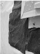

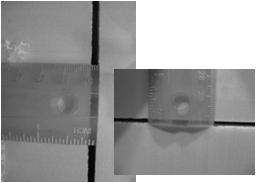
18 Material deformation and loss of adhesion Joints open E. I. DuPont de Nemours and Company All rights reserved 18

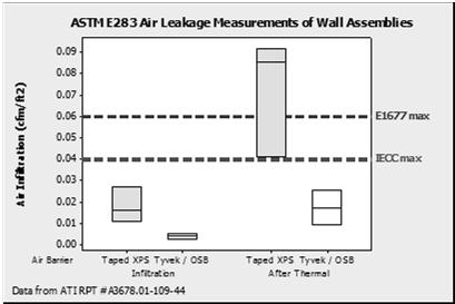
19 Taped rigid insulation is not allowed as an air barrier in Wisconsin. When some types of insulation boards get colder by 70oF, they can shrink ¼ on all sides. The tape cannot adequately perform under such circumstances. - Air Barrier Update, International Masonry Institute Technology Brief, January Energy efficiency Structural performance Fire resistance Water management NFPA 285: Standard Fire Test Method for Evaluation of Fire Propagation Characteristics of Exterior Non-Load Bearing Wall Assemblies Containing Combustible Components. Tests fire performance of the wall assembly to be used on a project. Required by code when certain combustible materials are specified to be used in a non-combustible wall assembly Applies to exterior walls of Type I-IV Construction Triggered by when specific combustible materials are specified components of the wall assembly: Combustible insulation (pre-2012 IBC) Combustible claddings (pre-2012 IBC & 2012 IBC) Combustible air & water barriers (2012 IBC) Vertical and Lateral Flame Propagation. Exterior walls on buildings of Type I, II, III or IV construction that are greater than 40 feet (12192 mm) in height above grade plane and contain a combustible water-resistive barrier shall be tested in accordance with and comply with the acceptance criteria of NFPA
20 NFPA 285 Triggers Mechanical equipment screens located on roof decks constructed of combustible materials ( ) igh-pressure Decorative Exterior- Grade Compact Laminates (PL) used as exterior wall coverings ( ) Metal composite materials (MCM), such as ACM, used as exterior wall coverings ( ) Foam plastic insulation ( ) Fiber-reinforced polymer (FRP) used on exterior walls (2612.6) Metal composite materials (MCM), such as ACM, used as exterior wall coverings ( ) Foam plastic insulation ( ) Fiber-reinforced polymer (FRP) used on exterior walls (2612.5) Metal composite materials (MCM), such as ACM, used as exterior wall coverings ( ) Foam plastic insulation ( ) Combustible water resistive barrier (1403.5) Water Management Minimize Maximize Wetting 1.Bulk Water 2. Air transport 3. Diffusion Drying 1. Drainage 2. Venting 3. Diffusion Good enclosure water management design and detailing will minimize the risk of wetting, but drying potential must ALWAYS be considered Air Barriers, Water-resistive Barriers and Vapor Barriers Air barriers can be placed anywhere in the wall. Water-resistive Barrier Vapor Barrier 20


21 Air Transported Moisturemust not be confused with Vapor Diffusion Air Transported Moisture P o > P i Water Vapor Diffusion VP* o > VP* i 98% of all water vapor migration Free ride ~ 2% of all water vapor Slow Molecular migration Movement * Vapor pressure is proportional to Water Vapor Concentration E. I. DuPont de Nemours and Company All rights reserved Where are interior vapor retarders required? 2006: Above Blue Line 2003: Above White Line 21

22 SECTION 8 International Residential Code (2009/ 2012): Condensation Protection Requirements R702.7 Vapor retarders. Class I or II vapor retarders are required on the interior side of frame walls in Climate Zones 5, 6, 7, 8 and Marine 4. Exceptions: 1. Basement walls. 2. Below grade portion of any wall. 3. Construction where moisture or its freezing will not damage the materials. SECTION 8 Since IBC 2009 Class III Vapor Retarders allowed in cold climates Includes vinyl and brick with airspace Specific sheathing R-Values dependent on climate. SECTION 8 International Residential Code (2009/2012): Condensation Protection Requirements R Class III vapor retarders. Class III vapor retarders shall be permitted where any one of the conditions in Table R is met. R Material vapor retarder class. The vapor retarder class shall be based on the manufacturer s certified testing or a tested assembly. The following shall be deemed to meet the class specified: Class I: Sheet polyethylene, unperforated aluminum foil. Class II: Kraft-faced fiberglass batts. Class III: Latex or enamel paint. R Minimum clear air spaces and vented openings for vented cladding. For the purposes of this section, vented cladding shall include the following minimum clear air spaces. Other openings with the equivalent vent area shall be permitted. 1. Vinyl lap or horizontal aluminum siding applied over a weather resistive barrier as specified in Table R Brick veneer with a clear airspace as specified in Table R Other approved vented claddings. 22

23 Total Moisture Content of Wall System Simulated 3 months starting July 1. Data originally submitted to Texas Residential Constuction Council Task-Group on Mold and Moisture Gypsum Board R Simulated 3 months starting July 1. Data originally submitted to Texas Residential Constuction Council Task-Group on Mold and Moisture New Language 2015 IBC Vapor retarders. Vapor retarders as described in Section shall be provided in accordance with Sections and , or an approved design using accepted engineering practice for hygrothermalanalysis Class I and II Vapor Retarders. Class I or II vapor retarders shall not be provided on the interior side of frame walls in Zones 1 and 2. Class I vapor retarders shall not be provided on the interior side of frame walls in Zones 3 and 4. Class I or II vapor retarders shall be provided on the interior side of frame walls in Zones 5, 6, 7, 8 and Marine 4. The appropriate zone shall be selected in accordance with Chapter 3 of the International Energy Conservation Code. Exceptions: 1. Basement walls. 2. Below-grade portion of any wall. 3. Construction where moisture or its freezing will not damage the materials. 4. Conditions where Class III vapor retarders are required in Section Class III vapor retarders. Class III vapor retarders shall be permitted where any one of the conditions in Table is met. Only Class III vapor retarders shall be used on the interior side of frame walls where foam plastic insulating sheathing with perm rating of less than 1 perm is applied in accordance with Table on the exterior side of the frame wall. 23


24 Section 3: Whole Building Airtightness: Blower Door Testing and Diagnostic Tool 3 Building Test ASTM E779 SECTION 3 US ome Airtightness Source: 2009 ASRAE andbook of Fundamentals 24
 is the measure of air leakage used in ResDB. Roughly speaking, NL = 0.")

25 SECTION 3 LBNL Data Base SECTION 3 Source: LBNL Report Number 53367: Chan, W. R, et al, Analysis of U.S. Residential Air Leakage Database, Indoor Environment Department, Lawrence Berkeley National Laboratory, July 2003 E. I. DuPont de Nemours and Company All rights reserved SECTION 3 Normalized Leakage of U.S. omes Normalized leakage (NL) is the measure of air leakage used in ResDB. Roughly speaking, NL = 0.55 corresponds to AC50 = 10 (i.e. 10 air changes per hour at a pressure difference of 50 Pa). ome Counts NL Geometric Mean NL Geometric Standard Deviation Single-Family Detached omes Single-Family Attached omes 135, , Multi-Family omes 2, Manufactured omes 8, E. I. DuPont de Nemours and Company All rights reserved 25


26 Residential Air Leakage Sequential Testing: IBACOS Lab ouse Stage ousewrap installed: Window and door openings andother penetrations integrated with air barrier and drainage plane After spray foam installed in attic, strategically sealing penetrations in 2 nd floor ceiling plane Tested Air Leakage 3.0 AC 50 ousewrap as primary air barrier required great attention to detail but it worked 0.88 AC 50 After spray foam in the band joists 0.77 AC 50 After wall cavity insulation and drywall installed 0.65 AC 50 Complete 0.54 AC 50 Ultimate target was Passivhaus level of airtightness, which is 0.6 Source: Oberg, B, Energy Efficiency Lab ome: Case Study, EEBA Conference, September SECTION 3 Whole Building Airtightness Testing: US Army Corps of Engineers (USACE) Standard All new buildings must: 1. Achieve an air leakage rate not to exceed 0.25 cfm/ft 75Pa 2. Pass an air leakage test per ASTM E779 26


27 3 USACE Standard Experience Current USACE Standard (0.25 cfm/ft 75Pa ) Future USACE Standard: (0.15 cfm/ft 75Pa ) Up to 80% more airtight than current USACE Standard Source: Dr. Alexander Zhivov, USACE ERDC, Champaign, USA: AIVC Workshop, June 14, 2010, Brussels, Belgium 3 Implementing USACE Air tightness Requirements: A General Contractor s Perspective Follow the details know what items are part of the continuous air barrier; attention to detail is critical in design and construction Materials compatibility make sure the materials specified are compatible Manufacturers installation instruction engage manufacturers representatives for training, site visits, inspections Verify & document make sure that the details are being followed. Sealing the envelope is cheap during construction but more expensive afterwards (cost 10 to 1000X more afterwards). Source: ensel Phelps Construction Co. SECTION 3 27


28 SECTION 3 SECTION 3 SECTION 3 28


29 SECTION 3 SECTION 3 SECTION 3 29
2006 INTERNATIONAL ENERGY CONSERVATION CODE
 2006 INTERNATIONAL ENERGY CONSERVATION CODE DOCUMENTATION Code Change No: EC28-06/07 Original Proposal Sections: IECC: 202, 402.5, 402.5.1 (New), Table 402.5.1 (New), 402.5.2 (New), 402.5.3 (New), 402.2.8,
Hardin County Planning and Development Commission
 Location by Climate Zone: Hardin County (per Table N1101.2), and the entire state of Kentucky is located in Climate Zone 4, the HDD is 4000 to 4999. Building Requirements; Building Thermal Envelope The
Michigan Energy Code Training and Implementation Program
 Michigan Energy Code Training and Implementation Program 1.0 Hour Advanced Program Course Number 16201 Residential Energy Air Sealing School of Planning, Design & Construction Michigan State University
2015 Michigan Residential Code Energy Worksheet for New Single-family Residential Building
 2015 Michigan Residential Code Energy Worksheet for New Single-family Residential Building Building Department 52700 Van Dyke, Shelby Township, MI 48316 Phone (586) 731-5969 Fax (586) 803-2099 building@shelbytwp.org
Feature Zone IECC 2009 IECC
 Feature Zone 3 2006 IECC 2009 IECC Window U factor 0.65 0.50 Skylight U factor 0.65 0.65 Window SHGC 0.40 0.30 Ceiling R value 30 30 Wood frame R value 13 13 Mass wall R value 1 5 5/8 Floor R value 19
Boulder City NV Prepared by (Print Name) Signature Date
 Signature Date") City of Boulder City Community Development Department Building & Safety Division 401 California Avenue Boulder City, NV 89005-2600 702-293-9282 (Main Line) 702-293-9392 (Fax) 2009 International Energy
City of Boulder City Community Development Department Building & Safety Division 401 California Avenue Boulder City, NV 89005-2600 702-293-9282 (Main Line) 702-293-9392 (Fax) 2009 International Energy
Chicago Roofing Contractors Association
 Chicago Roofing Contractors Association CSI Chicago Specifiers Roundtable CRCA Report Illinois 1/1/2013 Adoption ICC s 2012 International Energy Conservation Code Bill McHugh, CRCA Executive Director &
Moisture Considerations for Insulated Building Assemblies
 PHRC Webinar Series Tuesday, November 10, 2015 @ 1pm Description Moisture Considerations for Insulated Building Assemblies Brian Wolfgang Housing Systems Specialist One critical design consideration in
November 10, 2015 Baltimore, MD. presented by
 Baltimore, MD 2015 I code R values and best practices presented by Mark S. Graham Associate Executive Director, Technical Services National Roofing Contractors Association (NRCA) 1 IBC 2015: Ch. 15: Roofing
Date Rater Verified. Rater Verified. Slab / Pre-Drywall / Thermal Inspection
 Slab on Grade & Basements: A capillary break is installed on top of all footings Slab / Pre-Drywall / Thermal Inspection A minimum of 4" of clean or washed gravel (0.5" diameter or greater) is placed over
Insulation, Fireblocking, Draftstopping and Crawl Space Requirements REVISION DATE: JANUARY 2017
 City of Republic Community Development Department Insulation, Fireblocking, Draftstopping and Crawl Space Requirements REVISION DATE: JANUARY 2017 Insulation Requirements Insulation (2012 IRC Section R302.10.1):
Inspection of New One- and Two- Family Dwellings
 Building Safety Division 8500 Santa Fe Drive Overland Park, KS 66212 (913) 895-6225 Fax (913) 895-5016 Email: permitservices@opkansas.org Inspection of New One- and Two- Family Dwellings Planning and Development
Air Barrier Requirements for Low-Slope Roof Assemblies Myths vs. Facts
 Air Barrier Requirements for Low-Slope Roof Assemblies Myths vs. Facts Peter Kalinger Canadian Roofing Contractors Association Dr. B. Baskaran National Research Council of Canada 1 Air Leakage Controlling
Instructions for the Residential Building Data Collection Checklist 2009 International Energy Conservation Code with 2011 Georgia Amendments
 Instructions for the Residential Building Data Collection Checklist 2009 International Energy Conservation Code with 2011 Georgia Amendments Use of these instructions with a residential data collection
INSTALLING WATER-RESISTIVE BARRIERS & FLASHING
 INSTALLING WATER-RESISTIVE BARRIERS & FLASHING IN A TWO-LAYER STUCCO APPLICATION Fortifiber Building Systems Group provides this guide to assist installers by demonstrating a two-layer installation of
Incorporating Insulating Sheathing into the Design of the Thermal and Moisture Management System of the Building Enclosure
 Incorporating Insulating Sheathing into the Design of the Thermal and Moisture Management System of the Building Enclosure Peter Baker, Building Science Corporation ABSTRACT With rising utility cost, concerns
Fenestration Components: Mechanical Summary. Water heater energy factor: Ef Fuel type: Gas Electric Other
 This information must be on the drawing documents not attached to plans. The following Compliance statements must be on the drawings: 2009 International Energy Conservation Code Statement of acknowledgement
2012 IECC Residential with State Adopted Changes
 2012 IECC Residential with State Adopted Changes Salt Lake County Townships 385-468-6694 801-381-1449 bursenbach@slco.org bursenbach@yahoo.com BUILDING TALK 1 2 The Family of I-Codes International Building
RESIDENTIAL ENERGY EFFICIENCY
 CHAPTER 4 RESIDENTIAL ENERGY EFFICIENCY SECTION 401 GENERAL 401.1 Scope. This chapter applies to residential buildings. 401.2 Compliance. Projects shall comply with Sections 401, 402.4, 402.5, and 403.1,
IRC 2012 Key Changes
 IRC 2012 Key Changes Overview of changes between the 2009 and 2012 IRC A Webinar Provided by The Pennsylvania Housing Research Center November 4, 2011 Presented by Mike Turns; Associate Director, PHRC
Interpretation Variables and Common Areas of Confusion. Of the 2009 IECC
 Interpretation Variables and Common Areas of Confusion Of the 2009 IECC 1. (Mandatory) provisions vs. (Prescriptive) provisions: The IECC contains flexibility by allowing different approaches to achieve
Prescriptive Checklist for the 2015 Washington State Energy Code
 Prescriptive Checklist for the 2015 Washington State Energy Code Chapter 51-11R WAC STATE BUILDING CODE ADOPTION AND AMENDMENT OF THE 2015 EDITION OF THE INTERNATIONAL ENERGY CONSERVATION CODE, RESIDENTIAL
Building Enclosure Performance for Existing and New Buildings
 Building Enclosure Performance for Existing and New Buildings 2015 HESNI Annual Conference Rick Ziegler, PE Industry Construction Defect Claims Building Envelope - 70% Plumbing - 12% Freezing - 4% Fire
Spray Polyurethane Foam. Insulation and Air Barrier Requirements of the 2012 I-Codes. Spray Foam Coalition
 Spray Polyurethane Foam Design Guidance Insulation and Air Barrier Requirements of the 2012 I-Codes Spray Foam Coalition about the collaboration the center for the polyurathanes industry (CPI) of the
Smart Vapor Retarders
 CertainTeed Smart Vapor Retarders Insulation B UILDING S CIENCE SMART VAPOR RETARDERS: A TECHNOLOGY PRIMER For years, builders have relied on a dual climate-zone classification for the placement of vapor
DIVISION: THERMAL AND MOISTURE PROTECTION SECTION: WATER RESISTIVE BARRIERS/WEATHER BARRIERS SECTION: AIR BARRIERS
 0 Most Widely Accepted and Trusted ICC ES Evaluation Report ICC ES 000 (800) 423 6587 (562) 699 0543 www.icc es.org ESR 1993 Reissued 08/2017 This report is subject to renewal 08/2018. DIVISION: 07 00
Trusted ICC ES DIVISION: ATLANTA, CGF PRO, ENERGYS. Look. Conformity! Evaluation. ICC-ES Evaluation
 0 Most Widely Accepted and Trusted ICC ES Evaluation Report ICC ES 000 (800) 423 6587 (562) 699 0543 www.icc es.orgg DIVISION: 07 00 00 THERMAL AND MOISTURE PROTECTION SECTION: 07 21 00 THERMAL INSULATION
Alternate Means and Materials for Code Compliance
 Alternate Means and Materials for Code Compliance RESNET Conference February 29, 2016 Theresa A. Weston, PhD DuPont Protective Solutions Learning Objectives Understand how building codes effect innovation
United States Army Corp of Engineers Requirements for Air Barrier Systems in Buildings
 United States Army Corp of Engineers Requirements for Air Barrier Systems in Buildings Timothy R. Posey, MBC, Scott W. Kramer, Ph.D. and Mark C. Tatum, P.E. Auburn University Auburn, Alabama This study
ESR-2072 Reissued September 1, 2013 This report is subject to renewal September 1, 2015.
 ICC-ES Evaluation Report www.icc-es.org (800) 423-6587 (562) 699-0543 ESR-2072 Reissued September 1, 2013 This report is subject to renewal September 1, 2015. A Subsidiary of the International Code Council
Michigan Energy Code Training and Implementation Program
 Michigan Energy Code Training and Implementation Program 1.0 Hour Advanced Program Course Number 16202 Residential Energy Plan Review School of Planning, Design & Construction Michigan State University
2010 National Building Code Adoption and Associated Process Changes
 Building Inspection City of Moncton 655 Main Street Moncton, NB E1C 1E8 Phone: (506) 856-4375 Fax: (506) 856-4348 Bulletin No. 14 From: Randy Richard Date: February 9, 2015 Subject: 2010 National Building
City of High Point Airport Overlay District Noise Level Reduction Design Standards
 City of High Point Airport Overlay District Noise Level Reduction Design Standards Part A. Residential Design Standards for Zone 3 I. NOISE LEVEL REDUCTION (NLR) REQUIREMENT FOR ZONE 3. The City of High
THE GEORGIA ENERGY CODE: 2009 IECC + AMENDMENTS
 THE GEORGIA ENERGY CODE: 2009 IECC + AMENDMENTS For the Georgia Association of Home Inspectors Bourke Reeve ABOUT SOUTHFACE 1 EARTHCRAFT Regional Green Building Program HISTORY OF ENERGY CODES MEC 1992,
APPROVED. Acceptable to the code official for compliance with the provisions of the applicable Code or referenced Standard.
 Chapter 1 101.1 Title. These regulations shall be known as the North Carolina Energy Conservation Code as approved by the North Carolina Building Code Council on March 11, 2008, to be effective January
DIVISION: THERMAL AND MOISTURE PROTECTION SECTION: THERMAL INSULATION REPORT HOLDER: CERTAINTEED CORPORATION
 0 Most Widely Accepted and Trusted ICC ES Report ICC ES 000 (800) 423 6587 (562) 699 0543 www.icc es.org ESR 3758 Reissued 04/2017 This report is subject to renewal 04/2018. DIVISION: 07 00 00 THERMAL
DuPont Tyvek Air Barrier Installation Guidelines. Canadian Version. Version 2
 DuPont Tyvek Air Barrier Installation Guidelines Helping you get the job done right Canadian Version Version 2 Table of Contents Applicable Products...2 Required Materials...2 Code Requirements...3 General
DIVISION: THERMAL AND MOISTURE PROTECTION SECTION: THERMAL INSULATION REPORT HOLDER: DEMILEC (USA) LLC
 LLC") 0 ICC ES Report ICC ES (800) 423 6587 (562) 699 0543 www.icc es.org 000 Most Widely Accepted and Trusted ESR 3210 Valid: 03/15 to 03/16 DIVISION: 07 00 00 THERMAL AND MOISTURE PROTECTION SECTION: 07 21
0 ICC ES Report ICC ES (800) 423 6587 (562) 699 0543 www.icc es.org 000 Most Widely Accepted and Trusted ESR 3210 Valid: 03/15 to 03/16 DIVISION: 07 00 00 THERMAL AND MOISTURE PROTECTION SECTION: 07 21
Integrated Air & Water Barrier Systems
 Integrated Air & Water Barrier Systems Presented by [ Jeff Presenter s Key, Georgia-Pacific Name ] Wood Products AIA Course: GP-FF-WRBAB Credit Designation: LU HSW Please add relevant logo here Disclaimer:
DIVISION: THERMAL AND MOISTURE PROTECTION SECTION: WATER RESISTIVE BARRIERS/WEATHER BARRIERS SECTION: AIR BARRIERS
 0 Most Widely Accepted and Trusted ICC ES Evaluation Report ICC ES 000 (800) 423 6587 (562) 699 0543 www.icc es.org ESR 2375 Reissued 10/2017 This report is subject to renewal 10/2018. DIVISION: 07 00
SAN MIGUEL COUNTY & TOWN OF MOUNTAIN VILLAGE BUILDING DEPARTMENTS PRESCRIPTIVE ENERGY CODE & GREEN BUILDING STANDARD
 SAN MIGUEL COUNTY & TOWN OF MOUNTAIN VILLAGE BUILDING DEPARTMENTS PRESCRIPTIVE ENERGY CODE & GREEN BUILDING STANDARD The Prescriptive Energy Code & Green Building Standard requirements for San Miguel County
Low-cost Construction for High-energy Savings. Brian J. Wimmer Construction Manager Rochester Area Habitat for Humanity
 Low-cost Construction for High-energy Savings Brian J. Wimmer Construction Manager Rochester Area Habitat for Humanity construction@rahh.org Objectives: 1. Control air & moisture in high-performance, low-cost
REPORT HOLDER: THE DOW CHEMICAL COMPANY 1501 LARKIN CENTER DRIVE MIDLAND, MICHIGAN EVALUATION SUBJECT:
 0 Most Widely Accepted and Trusted ICC-ES Evaluation Report ICC-ES 000 (800) 423-6587 (562) 699-0543 www.icc-es.org ESR-3089 Reissued 07/2016 This report is subject to renewal 07/2018. DIVISION: 07 00
DIVISION: THERMAL AND MOISTURE PROTECTION SECTION: THERMAL INSULATION REPORT HOLDER: DEMILEC (USA) INC.
 INC.") 0 Most Widely Accepted and Trusted ICC ES Evaluation Report ICC ES 000 (800) 423 6587 (562) 699 0543 www.icc es.org ESR 4073 Issued 08/2017 This report is subject to renewal 08/2018. DIVISION: 07 00 00
0 Most Widely Accepted and Trusted ICC ES Evaluation Report ICC ES 000 (800) 423 6587 (562) 699 0543 www.icc es.org ESR 4073 Issued 08/2017 This report is subject to renewal 08/2018. DIVISION: 07 00 00
PREP + INSULATION. DISCLAIMER: These tools are for illustrative purposes only and
 PREP + INSULATION HOME ENERGY UPGRADES What every contractor needs to know. Copyright 2012 Advanced Energy. All Rights Reserved 103 HOME ENERGY UPGRADES Prep + Insulation Contents Air sealing is a challenging
Advanced technologies for enhancing the building envelope. 3M Building and Construction Market
 Advanced technologies for enhancing the building envelope 3M Building and Construction Market Controlling air is crucial for the health & energy efficiency of buildings Ensuring you have the right air
ESR-1826 Reissued February 1, 2013 This report is subject to renewal February 1, 2015.
 * ICC-ES Evaluation Report www.icc-es.org (800) 423-6587 (562) 699-0543 ESR-1826 Reissued February 1, 2013 This report is subject to renewal February 1, 2015. A Subsidiary of the International Code Council
DuPont. Tyvek Sheathing Membrane Installation Guidelines. Version 2. Canadian Version
 DuPont Tyvek Sheathing Membrane Installation Guidelines Helping you get the job done right Canadian Version Version 2 Table of Contents Applicable Products...2 Required Materials...2 Code Requirements...3
ESR-1655 Reissued April 2014 This report is subject to renewal April 1, 2016.
 ICC-ES Evaluation Report www.icc-es.org (800) 423-6587 (562) 699-0543 ESR-1655 Reissued April 2014 This report is subject to renewal April 1, 2016. A Subsidiary of the International Code Council DIVISION:
Trusted DIVISION: 07 SYSTEM. Conformity! ICC-ES Evaluation. not specifically. Copyright 2014
 0 ICC ES Report ICC ES (800) 423 6587 (562) 699 0543 www.icc es.orgg 000 Most Widely Accepted and Trusted ESR 3052 Valid: 11/14 to 11/16 DIVISION: 07 00 00 THERMAL AND MOISTURE PROTECTION SECTION: 07 21
Single Family Residence Building Permits
 Village of Northbrook Department of Building & Development Guide to: Designing, Documenting & Inspecting For Energy Code Compliance Single Family Residence Building Permits New Construction Additions Alterations
SECTION SLOPED TRANSLUCENT METAL SKYLIGHT SYSTEM
 PART 1- GENERAL 1.1 SUMMARY A. Section Includes: SECTION 084523 - SLOPED TRANSLUCENT METAL SKYLIGHT SYSTEM 1. Flat factory prefabricated structural insulated translucent sandwich panels; with glazed endwalls.
Questar ThermWise Duct Technical Specifications
 Questar ThermWise Duct Technical Specifications 1. Introduction and Scope: This document sets forth the specifications for duct sealing and duct insulation in accordance to Questar ThermWise Weatherization
NEXT GENERATION HIGH PERFORMANCE WALLS
 CONSTRUCTION GUIDE NEXT GENERATION HIGH PERFORMANCE WALLS CLIMATE ZONES 3-5 PART 2: 2X4 Walls with 1" 1.5" Exterior Insulative Sheathing V. Kochkin and J. Wiehagen Home Innovation Research Labs June 2017
MULTI-FAMILY USER S BULLETIN FOR INSTALLATION OF DUPONT WEATHERIZATION SYSTEMS PRODUCTS
 USER S BULLETIN MULTI-FAMILY USER S BULLETIN FOR INSTALLATION OF DUPONT WEATHERIZATION SYSTEMS PRODUCTS CONTENTS Introduction...1 Use of this Residential Multi-Family User s Bulletin...1 DuPont Multi-Family
2015 IECC Whole Building Air Leakage Compliance
 2015 IECC Whole Building Air Leakage Compliance Presented by: Jeffrey Crowe, PE Project Manager www.becx.com www.pieglobal.com September 2012 Learning Objectives Understand 2015 International Energy Code
CHAPTER 26 PLASTIC SECTION BC 2601 SECTION BC 2603 GENERAL FOAM PLASTIC INSULATION
 CHAPTER 26 PLASTIC SECTION BC 2601 GENERAL 2601.1 Scope. These provisions shall govern the materials, design, application, construction and installation of foam plastic, foam plastic insulation, plastic
Administrative Changes
 Revised 11/29/06 Knox County Residential Building Codes Significant Changes From The 1995 CABO One And Two Family Dwelling Code To The 2006 International Residential Code All one and two family dwellings
Plan Check & Field Inspection Guide
 Plan Check & Field Inspection Guide 1992 MEC, 1993 MEC, and 1995 MEC Inside This Guide Plan Check Field Inspection Plan Check Building plans and specifications must be submitted with each building application
2001 National Workshop on State Building Energy Codes July th, 2001 Burlington, Vermont
 2001 National Workshop on State Building Energy Codes July 16-19 th, 2001 Burlington, Vermont A Systems Engineering Approach to the Design of Energy and Resource Efficient Homes Presented By: Mark LaLiberte
A. Source Limitations: Obtain each type of building insulation through one source.
 SECTION 07210 - BUILDING INSULATION PART 1 - GENERAL 1.1 RELATED DOCUMENTS A. Drawings and general provisions of the Contract, including General and Supplementary Conditions and Division 1 Specification
DIVISION: THERMAL AND MOISTURE PROTECTION SECTION: THERMAL INSULATION REPORT HOLDER: DEMILEC (USA) INC.
 INC.") 0 Most Widely Accepted and Trusted ICC ES Evaluation Report ICC ES 000 (800) 423 6587 (562) 699 0543 www.icc es.org ESR 3883 Reissued 08/2017 This report is subject to renewal 04/2018. DIVISION: 07 00
0 Most Widely Accepted and Trusted ICC ES Evaluation Report ICC ES 000 (800) 423 6587 (562) 699 0543 www.icc es.org ESR 3883 Reissued 08/2017 This report is subject to renewal 04/2018. DIVISION: 07 00
Compliance Certificate
 REScheck Software Version 4.6.4 Compliance Certificate Project RESIDENCE Energy Code: 2009 IECC Location: Perkasie, Pennsylvania Construction Type: Single-family Project Type: New Construction Conditioned
Energy Efficiency: Designing Wood-Frame Buildings for Occupant Comfort
 Please add relevant logo here Energy Efficiency: Designing Wood-Frame Buildings for Occupant Comfort Presented by: Peter J. Arsenault, FAIA, NCARB, LEED-AP Disclaimer: This presentation was developed by
(Project Location) (your firm's name)
 (your firm's name)") SECTION 07 21 00 THERMAL INSULATION PART 1 GENERAL 1.1 RELATED DOCUMENTS A. Drawings and general provisions of the Contract, including the Conditions of the Contract and Division 01 Specification Sections
SECTION 07 21 00 THERMAL INSULATION PART 1 GENERAL 1.1 RELATED DOCUMENTS A. Drawings and general provisions of the Contract, including the Conditions of the Contract and Division 01 Specification Sections
Pella 250 Series. Wood Frame Construction with Vinyl Siding... V250-ID-888 Wood Frame Construction with Brick Veneer...
 SECTION DIRECTORY General Information Introduction... V250-ID-886 Installation Accessories and Applications... V250-ID-886 Typical Sealant Placement Details... V250-ID-887 Fin Installation Details Wood
DIVISION: THERMAL AND MOISTURE PROTECTION SECTION: THERMAL INSULATION REPORT HOLDER: NATURAL POLYMERS, LLC
 0 Most Widely Accepted and Trusted ICC-ES Evaluation Report ICC-ES 000 (800) 423-6587 (562) 699-0543 www.icc-es.org ESR-3136 Reissued 06/2017 This report is subject to renewal 06/2018. DIVISION: 07 00
HPW Protocol Reference Manual
 1 HPW Protocol Reference Manual Change Log: UPDATED BY DATE UPDATED VERSION UPDATE DETAILS 2 Table of Contents: HIGH PERFORMANCE WALL ASSEMBLY... 4 THERMAL SPECIFICATION... 4 REQUIREMENTS FOR HPW INSULATION...
Application Specification:
 Application Specification: GacoFireStop2 F5001 (Half-Pound) March 2014 Supersedes 7/11 Division: 07 21 19 GUIDE SPECIFICATION GacoFireStop2 F5001 INSULATION PART 1 GENERAL This guide specification discusses
Crawl Space Moisture Control
 Crawl Space Moisture Control Crawl space foundations are found in many homes. Typically, these foundation types are equipped with operable vents designed to provide ventilation for moisture control. Unfortunately,
CHAPTER 1: OVERVIEW OF ENERGY EFFICIENT CONSTRUCTION
 Chapter 1: Overview of Energy Efficient Construction 1 CHAPTER 1: OVERVIEW OF ENERGY EFFICIENT CONSTRUCTION Chapter 1 is a quick reference guide that discusses the key components and features of energy
UNIFIED FACILITIES GUIDE SPECIFICATIONS
 USACE / NAVFAC / AFCEC / NASA UFGS-07 27 10.00 10 (May 2014) ----------------------------------- Preparing Activity: USACE UFGS-07 08 27.00 10 (February 2013) UNIFIED FACILITIES GUIDE SPECIFICATIONS References
VELUX America Inc. SPECIFICATION FOR MODEL QPF SELF-FLASHED FIXED SKYLIGHT SECTION UNIT SKYLIGHTS
 SECTION 08620 UNIT SKYLIGHTS PART 1 GENERAL 1.01 SECTION INCLUDES A. Performance and product component information for VELUX QPF selfflashed fixed skylight. B. Unit skylight mounted directly to roof decking.
DIVISION: THERMAL AND MOISTURE PROTECTION SECTION: THERMAL INSULATION REPORT HOLDER: THE SPRAY MARKET, INC.
 0 Most Widely Accepted and Trusted ICC ES Evaluation Report ICC ES 000 (800) 423 6587 (562) 699 0543 www.icc es.org ESR 4195 Issued 12/2017 This report is subject to renewal 06/2018. DIVISION: 07 00 00
Recommended Amendments to the 2012 International Residential Code (IRC)
") Issue: Insulation Requirements by Components- Basement Wall R-value and U-value 2012 IECC Section: Table N1102.1.1 and Table N1102.1.3 Modify the Tables as shown below: (Delete data, add new data) CLIMATE
Issue: Insulation Requirements by Components- Basement Wall R-value and U-value 2012 IECC Section: Table N1102.1.1 and Table N1102.1.3 Modify the Tables as shown below: (Delete data, add new data) CLIMATE
2013 COMMERCIAL PRODUCTS
 2013 COMMERCIAL PRODUCTS EXPLORE GEOMETRY AND SPACE WITHOUT COMPROMISING BUILDING ENVELOPE PERFORMANCE Commercial design considerations come with very specific challenges that can t be addressed with just
The Role of Control Layers in Building Enclosure Design
 The Role of Control Layers in Building Enclosure Design COLIN SHANE M.ENG., P.ENG. ASSOCIATE, SENIOR PROJECT MANAGER OCTOBER 13, 2016 Disclaimer: This presentation was developed by a third party and is
Slab edge insulation is one of
 How to Properly Insulate a Slab Presented by: Mike Turns, Associate Director, PHRC Tuesday, April 10, 2012 1:00 PM www.enrg.psu.edu/phrc 4 Slab edge insulation is one of the most abused details in construction.
DIVISION: THERMAL AND MOISTURE PROTECTION SECTION: THERMAL INSULATION REPORT HOLDER: ICYNENE, INC.
 0 Most Widely Accepted and Trusted ICC-ES Evaluation Report ICC-ES 000 (800) 423-6587 (562) 699-0543 www.icc-es.org ESR-3500 Reissued 01/2017 This report is subject to renewal 01/2018. DIVISION: 07 00
DIVISION: THERMAL AND MOISTURE PROTECTION SECTION: THERMAL INSULATION SECTION: WATER-RESISTIVE BARRIERS/WEATHER BARRIERS
 0 Most Widely Accepted and Trusted ICC-ES Evaluation Report ICC-ES 000 (800) 423-6587 (562) 699-0543 www.icc-es.org ESR-3493 Reissued 09/2017 This report is subject to renewal 09/2018. DIVISION: 07 00
SECTION MODIFIED BITUMINOUS MEMBRANE ROOFING Peel & Roof
 SECTION 07550 MODIFIED BITUMINOUS MEMBRANE ROOFING Peel & Roof This section is based on the products of MFM Building Products Corp., which is located at: 525 Orange St. P. O. Box 340 Coshocton, OH 43812
WEB BASED APPLICATION SPECIFIC INSTALLATION INSTRUCTIONS
 WEB BASED APPLICATION SPECIFIC INSTALLATION INSTRUCTIONS Face Seal Fin and Integral J-Channel Install Although all possible measures have been taken to insure the accuracy of the material presented, WIXSYS,
REPORT HOLDER: HUBER ENGINEERED WOODS, LLC ONE RESOURCE SQUARE DAVID TAYLOR DRIVE, SUITE 300 CHARLOTTE, NORTH CAROLINA 28262
 0 Most Widely Accepted and Trusted ICC ES Evaluation Report ICC ES 000 (800) 423 6587 (562) 699 0543 www.icc es.org ESR 1474 Reissued 10/2016 This report is subject to renewal 10/2018. DIVISION: 06 00
CSI Boston Technical Paper No. 1: Specifying Air Barriers Air Barriers
 CSI Boston Technical Paper No. 1: Specifying Air Barriers 07 27 00 - Air Barriers CSI BOSTON TECHNICAL PAPER NO. 1: SPECIFYING AIR BARRIERS JULY 2014 1 TABLE OF CONTENTS Click on any heading below to be
INTERIOR ENVIRONMENT
 CHAPTER 12 INTERIOR ENVIRONMENT > SECTION 1201 GENERAL 1201.1 Scope. The provisions of this chapter shall govern ventilation, temperature control, lighting, yards and courts, sound transmission, room dimensions,
Avoiding Air Barrier Pitfalls When sub-trade activities are not in sync with air barrier requirements, installation can go poorly.
 48 D+D NOVEMBER 2013 Building Envelope Avoiding Air Barrier Pitfalls When sub-trade activities are not in sync with air barrier requirements, installation can go poorly. By Brian H. Neely, AIA, CDT, CBST,
DIVISION: THERMAL AND MOISTURE PROTECTION SECTION: THERMAL INSULATION SECTION: AIR BARRIERS REPORT HOLDER:
 0 ICC ES Report ICC ES (800) 423 6587 (562) 699 0543 www.icc es.org 000 Most Widely Accepted and Trusted ESR 2717 Reissued 07/2015 This report is subject to renewal 07/2017. DIVISION: 07 00 00 THERMAL
General Residential Code Requirements
 Residential building code review will be based on compliance with the requirements of the Louisiana State Uniform Construction code in accordance with ACT 12 of the 2005 First Extraordinary Session of
Why test a system that has already been tested? Typical Manufacturers information for window to wall interface and basis for reported test results.
 1 Pre-Construction Phase, & the Laboratory or Field Mock-Up Building Enclosure Commissioning: Train the Trainer Iowa State University, Ames Iowa May 10 12, 2016 Presented by Fiona Aldous Why test a system
EcoTouch Insulation with PureFiber Technology
 PROJECT ENGINEER RESPONSIBILITY: This is a general specification guide, intended to be used by experienced construction professionals, in conjunction with good construction practice and professional judgment.
CRITERIA FOR TESTING IMPACT & NON IMPACT RESISTANT BUILDING ENVELOPE COMPONENTS USING UNIFORM STATIC AIR PRESSURE
 TESTING APPLICATION STANDARD (TAS) 202-94 CRITERIA FOR TESTING IMPACT & NON IMPACT RESISTANT BUILDING ENVELOPE COMPONENTS USING UNIFORM STATIC AIR PRESSURE 1. Scope 1.1 This protocol covers procedures
DIVISION: THERMAL AND MOISTURE PROTECTION SECTION: THERMAL INSULATION SECTION: WATER-RESISTIVE BARRIERS/WEATHER BARRIERS
 0 Most Widely Accepted and Trusted ICC-ES Evaluation Report ICC-ES 000 (800) 423-6587 (562) 699-0543 www.icc-es.org ESR-1504 Reissued 03/2017 This report is subject to renewal 03/2018. DIVISION: 07 00
New Hampshire Residential Energy Code
 CHAIRMAN STATE OF NEW HAMPSHIRE EXECUTIVE DIRECTOR Thomas B. Getz AND SECRETARY COMMISSIONERS Debra A. Howland Susan S. Geiger TDD Access: Relay NH Nancy Brockway 1-800-735-2964 Tel. (603) 271-2431 FAX
Why Control Heat flow? How to Control Heat Flow? Thermal Performance. Modes of heat transfer: Thermal Control: Insulation & Thermal Bridges
 Fundamentals Insulation and Thermal Bridges June 13-14, 2012 Why Control Heat flow? Joseph Lstiburek, Ph.D., P.Eng John Straube, Ph.D., P.Eng 2012 Thermal Control: Insulation & Thermal Bridges 1. Occupant
Chapter 2: Foundation
 Chapter 2: Foundation Crawlspace [V502.1.2] [V502.1.2] [V502.1.3] Vents. Vents in the crawlspace help keep floor insulation and floor framing dry. Crawlspace vents also reduce the potential for radon buildup
Continuous Insulation Systems for Exterior Walls
 Continuous Insulation Systems for Exterior Walls High performance through sprayed-in-place foam insulation www.icynene.com Program Registration Icynene Inc. is a registered provider with The American Institute
REPORT HOLDER: JOHNS MANVILLE TH STREET DENVER, COLORADO EVALUATION SUBJECT:
 0 Most Widely Accepted and Trusted ICC-ES Evaluation Report ICC-ES 000 (800) 423-6587 (562) 699-0543 www.icc-es.org ESR-3398 Reissued 11/2017 This report is subject to renewal 11/2018. DIVISION: 07 00
CERTIFICATE OF FIELD VERIFICATION & DIAGNOSTIC TESTING (Page 1 of 8)
") CERTIFICATE OF FIELD VERIFICATION & DIAGNOSTIC TESTING (Page 1 of 8) Builder or Installer Name Builder or Installer Contact Telephone Plan/Permit (Additions or Alterations) Number Compliance Method (Prescriptive)
CERTIFICATE OF FIELD VERIFICATION & DIAGNOSTIC TESTING (Page 1 of 8) Builder or Installer Name Builder or Installer Contact Telephone Plan/Permit (Additions or Alterations) Number Compliance Method (Prescriptive)
ILLINOIS SPECIFIC AMENDMENTS TO THE IECC 2015 EDITION
 ILLINOIS SPECIFIC AMENDMENTS TO THE IECC 2015 EDITION CHAPTER 1 [CE] SCOPE AND ADMINSTRATION SECTION C101 SCOPE AND GENERAL REQUIREMENTS ClOl.1 Title. This code shall be known as the Illinois Energy Conservation
How to Meet Code and Manage Moisture in an Environment of Increasing Air Tightness Requirements. Ted Winslow
 How to Meet Code and Manage Moisture in an Environment of Increasing Air Tightness Requirements Ted Winslow 10.04.17 Builders are taking a Strategic Approach to Meet evolving building code requirements