research report Virginia Transportation Research Council Final Report VTRC 10-R11 D. STEPHEN LANE Associate Principal Research Scientist
|
|
|
- Christian Powell
- 5 years ago
- Views:
Transcription
1 Final Report VTRC 10-R11 Virginia Transportation Research Council research report Effect of Wet Curing Duration on Durability Parameters of Hydraulic Cement Concretes D. STEPHEN LANE Associate Principal Research Scientist Virginia Transportation Research Council, 530 Edgemont Road, Charlottesville, VA , (434)
2 Standard Title Page Report on Federally Funded Project 1. Report No.: 2. Government Accession No.: 3. Recipient s Catalog No.: FHWA/VTRC 10-R11 4. Title and Subtitle: 5. Report Date: Effect of Wet Curing Duration on Durability Parameters of Hydraulic Cement Concretes March Performing Organization Code: 7. Author(s): D. Stephen Lane 9. Performing Organization and Address: 8. Performing Organization Report No.: VTRC 10-R Work Unit No. (TRAIS): Virginia Transportation Research Council 530 Edgemont Road Charlottesville, VA Contract or Grant No.: Sponsoring Agencies Name and Address: 13. Type of Report and Period Covered: Virginia Department of Transportation 1401 E. Broad Street Richmond, VA Federal Highway Administration 400 North 8th Street, Room 750 Richmond, VA Final 14. Sponsoring Agency Code: 15. Supplementary Notes: 16. Abstract: Hydraulic cement concrete slabs were cast and stored outdoors in Charlottesville, Virginia, to study the impact of wet curing duration on durability parameters. Concrete mixtures were produced using portland cement, portland cement with slag cement, and portland cement with Class F fly ash concretes with water cementitious materials ratios (w/cm) of 0.45 and These concretes were subjected to immediate liquid membrane-forming curing or 1, 3, 7, or 14 days wet curing. Two slabs were cast for each of the wet curing durations. Following the curing period, one slab was allowed to dry naturally, and liquid membrane-forming curing compound was applied to the other. Three additional concretes containing saturated lightweight fine aggregate were produced to study the potential impact of internal curing on the durability parameters. These concretes contained portland cement with fly ash, silica fume, and both, at 0.35 w/cm. Three slabs were cast from each mixture and subjected to liquid membrane-forming curing, 1 or 3 days wet curing. The slabs were instrumented with humidity probes at two depths below the surface. Specimens were removed from two depths and tested for tensile strength, electrical conductivity, and sorptivity at 3 and 12 months of age. The success rate of the humidity measurements within the slabs was low because of water condensation. However, water condensation qualitatively indicates that the slabs did not dry out to an extent that would adversely impact concrete property development. Neither the strength, electrical conductivity, nor sorptivity results were impacted appreciably by the duration of moist curing. At most, 1 to 3 days wet curing was sufficient. Reducing w/cm had a positive impact on reducing permeability parameters, and previous work by others has shown the duration of curing needed to achieve discontinuity in the capillary pore system decreases with decreasing w/cm. No added benefit was observed by application of liquid membrane-forming curing following the wet curing. The prevailing weather conditions in the months during and following placement were humid, which would obviate any benefit from post wet-curing applications of liquid membrane-forming curing compound to slow drying. Prevailing weather conditions and the w/cm of the concrete mixture are important factors in determining adequate curing procedures and duration and should be considered by the project management team at the time of construction to establish appropriate procedures. A direct cost savings could be realized by removing the requirement for wet curing and using only in situations where it is likely to benefit the curing process. Alternatively, there may be long-term benefits that could be realized by applying these cost savings to the application of penetrating sealers, particularly for concretes that will be subjected early in their life to aggressive anti-icing and deicing programs. 17 Key Words: 18. Distribution Statement: Hydraulic cement concrete, wet curing, durability, conductivity, sorptivity, strength No restrictions. This document is available to the public through NTIS, Springfield, VA Security Classif. (of this report): 20. Security Classif. (of this page): 21. No. of Pages: 22. Price: Unclassified Unclassified 44 Form DOT F (8-72) Reproduction of completed page authorized
3 FINAL REPORT EFFECT OF WET CURING DURATION ON DURABILITY PARAMETERS OF HYDRAULIC CEMENT CONCRETES D. Stephen Lane Associate Principal Research Scientist In Cooperation with the U.S. Department of Transportation Federal Highway Administration Virginia Transportation Research Council (A partnership of the Virginia Department of Transportation and the University of Virginia since 1948) Charlottesville, Virginia March 2010 VTRC 10-R11
4 DISCLAIMER The contents of this report reflect the views of the author, who is responsible for the facts and the accuracy of the data presented herein. The contents do not necessarily reflect the official views or policies of the Virginia Department of Transportation, the Commonwealth Transportation Board, or the Federal Highway Administration. This report does not constitute a standard, specification, or regulation. Any inclusion of manufacturer names, trade names, or trademarks is for identification purposes only and is not to be considered an endorsement. Copyright 2010 by the Commonwealth of Virginia. All rights reserved. ii
5 ABSTRACT Hydraulic cement concrete slabs were cast and stored outdoors in Charlottesville, Virginia, to study the impact of wet curing duration on durability parameters. Concrete mixtures were produced using portland cement, portland cement with slag cement, and portland cement with Class F fly ash concretes with water cementitious materials ratios (w/cm) of 0.45 and These concretes were subjected to immediate liquid membrane-forming curing or 1, 3, 7, or 14 days wet curing. Two slabs were cast for each of the wet curing durations. Following the curing period, one slab was allowed to dry naturally, and liquid membrane-forming curing compound was applied to the other. Three additional concretes containing saturated lightweight fine aggregate were produced to study the potential impact of internal curing on the durability parameters. These concretes contained portland cement with fly ash, silica fume, and both, at 0.35 w/cm. Three slabs were cast from each mixture and subjected to liquid membrane-forming curing, 1 or 3 days wet curing. The slabs were instrumented with humidity probes at two depths below the surface. Specimens were removed from two depths and tested for tensile strength, electrical conductivity, and sorptivity at 3 and 12 months of age. The success rate of the humidity measurements within the slabs was low because of water condensation. However, water condensation qualitatively indicates that the slabs did not dry out to an extent that would adversely impact concrete property development. Neither the strength, electrical conductivity, nor sorptivity results were impacted appreciably by the duration of moist curing. At most, 1 to 3 days wet curing was sufficient. Reducing w/cm had a positive impact on reducing permeability parameters, and previous work by others has shown the duration of curing needed to achieve discontinuity in the capillary pore system decreases with decreasing w/cm. No added benefit was observed by application of liquid membrane-forming curing following the wet curing. The prevailing weather conditions in the months during and following placement were humid, which would obviate any benefit from post wet-curing applications of liquid membrane-forming curing compound to slow drying. Prevailing weather conditions and the w/cm of the concrete mixture are important factors in determining adequate curing procedures and duration and should be considered by the project management team at the time of construction to establish appropriate procedures. A direct cost savings could be realized by removing the requirement for wet curing and using only in situations where it is likely to benefit the curing process. Alternatively, there may be long-term benefits that could be realized by applying these cost savings to the application of penetrating sealers, particularly for concretes that will be subjected early in their life to aggressive anti-icing and deicing programs. iii
6 FINAL REPORT EFFECT OF WET CURING DURATION ON DURABILITY PARAMETERS OF HYDRAULIC CEMENT CONCRETES D. Stephen Lane Associate Principal Research Scientist INTRODUCTION Hydraulic cements and cement-pozzolan systems react with water to produce the cementitious paste that serves as the matrix of concrete. If the concrete dries too rapidly, the durability of the paste may be compromised by (1) stresses that develop causing cracking; and (2) insufficient hydration of the cementitious materials leaving a more continuous capillary pore system. Both serve to increase the ability of solutions to move through the concrete, facilitating deterioration mechanisms. Proper curing to restrict moisture loss is one of the basic steps in concrete construction. Current Virginia Department of Transportation (VDOT) specifications permit the following materials to be used in curing concrete: waterproof paper, polyethylene (PE) film, a combination of burlap and PE film, liquid membrane-forming compound (), and water. is by far the most commonly used material for curing pavements. For bridge decks, moist curing is required for a minimum of 7 days and until 70% of design compressive strength (f c) is achieved. For normal bridge deck construction, this can be accomplished using PE film with or without wet burlap, with the stipulation that the concrete surface under the PE film must remain moist for the duration of the moist-curing period. Wet burlap with PE film is required for concrete subject to the low-permeability specification and for hydraulic cement concrete bridge deck overlays. Immediately following the moist curing period, is applied. At a minimum age of 14 days and following the moist-curing period, closely spaced grooves are sawed transversely across the bridge deck surface to maintain good skid resistance. With the increased use of slag cement and pozzolans, both of which hydrate at a slower rate than portland cement, and a reduced water cementitious materials ratio (w/cm), some have emphasized the need for wet curing of critical elements, in particular, bridge decks, and some departments of transportation (DOTs) have instituted requirements for wet curing of up to 14 days for high performance concretes (HPC). Other concrete technologists have suggested that although the prompt application of moist curing to prevent water loss is critical, the benefits of moist curing diminish fairly rapidly so that beyond a few days, little actual benefit is realized with low w/cm concretes; a few have suggested that it may in fact be detrimental by contributing to increased cracking. The use of saturated, absorptive lightweight fine aggregate (LWFA) has been proposed as a method of providing water for internal curing of low w/cm concretes and thus achieving better curing of such concretes. Although VDOT has adopted requirements for wet curing of bridge decks, the construction industry has raised concerns about practicality and actual benefits. This study
7 examines these issues and provides information that will be useful in better defining appropriate curing practices for concrete construction. PURPOSE AND SCOPE The purpose of this study was to determine the effects of wet curing duration on the strength and transport properties of hydraulic cement concretes. This was a laboratory/field study. Test slabs were constructed from nine batches of ready-mixed concrete at an outdoor site in central Virginia and subjected to curing regimes including immediate application of wet curing up to 14 days duration and immediate application of a. Subsequently, the slabs were cored, and the cores tested for concrete properties. In addition, test cylinders were cast at the time the slabs were fabricated and subjected to a range of laboratory curing regimes prior to testing. METHODOLOGY Six hydraulic cement concretes with normal weight aggregates were produced at two w/cm: 0.35 and Three additional sets of concretes with 0.35 w/cm containing fly ash and/or silica fume were produced with absorptive LWFA to investigate this means of providing internal curing. The proportions for the concrete mixtures are shown in Table 1. All concretes were batched at ready-mixed concrete plants and delivered to the laboratory/field site in concrete mixing trucks. Test specimens for strength and transport properties were cast from fresh concrete and subjected to four curing regimes: (1) standard laboratory moist curing, (2) VDOT accelerated curing for permeability testing, (3) an extended 56-day moist curing, and (4) an accelerated 7-day curing. The slabs were cast in water-resistant forms that remained in place for the duration of the experiment to prevent drying from the sides or bottoms. Following strike-off, the top surface of the slabs was finished with a burlap drag. Subsequently, a bead of silicone caulk was placed at the junction of the slab surface and the form. For the normal-weight aggregate concretes, two slabs each were subjected to 1, 3, 7, and 14 days moist curing using wet burlap and PE film. Following cessation of wet curing, one slab was allowed to dry naturally; the other slab immediately received an application of. The ninth slab in each mixture received no moist curing, but was applied to the surface as soon as possible after finishing. A reduced set of three slabs each was fabricated from the three concrete mixtures with LWFA for internal curing. The proportion of the LWFA portion of these mixtures followed the practice described by Bentz et al. (2005). An outline of the slab-curing conditions is given in Table 2. 2
8 Table 1. Ingredient Proportions for Concrete Mixtures (Mass per Cubic Yard) Batch Ingredient A B C D E F G H I Portland Cement, lb % Silica Fume, lb % Slag Cement, lb % Class F Fly Ash, lb Coarse Aggregate, lb a Fine Aggregate (normal weight), lb Fine Aggregate (lightweight), lb Water, lb W/cm Air, % a The coarse aggregate in Batches B and E was crushed carbonate rock; in the remaining batches it was crushed granitic gneiss. Table 2. Outline of Curing Conditions for Slabs Batches and Slabs Curing Condition Batches A, B, C, D E, and F slabs 1 Liquid membrane-forming compound () after finishing 2 1 day wet burlap, allowed to dry 3 1 day wet burlap, following wet curing 4 3 days wet burlap, allowed to dry 5 3 days wet burlap, following wet curing 6 7 days wet burlap, allowed to dry 7 7 days wet burlap, following wet curing 8 14 days wet burlap, allowed to dry 9 14 days wet burlap, following wet curing Batches G, H, and I 1 after finishing 2 1 day wet burlap, allowed to dry, 3 3 days wet burlap, allowed to dry The slabs were instrumented with two humidity/temperature probes each at different depths (¾ in and 3 in) from the surface (Figures 1 and 2). To provide space and access to the probes, two lengths of 1-in outer diameter PVC pipe with screen covering the end were cast into the slabs at the desired depths. The probes were inserted the day of casting, within 2 to 3 hours after finishing was completed. At ages of 3 months and 1 year, 4-in-diameter cores were drilled and specimens taken from two depths (0 to 2 in and 3 to 5 in) for transport property testing. The transport property testing includes three methods: (1) bulk chloride diffusion (ASTM C 1556), which directly measures chloride ingress into concrete; (2) sorptivity (ASTM C 1585), which directly measures the rate of water absorption into the pore system of concrete at a given internal humidity condition; and (3) electrical conductivity, which indirectly assesses the connectivity of the pore system. Also at 3 months and 1 year, a 2-in-diameter core bit was drilled to selected depths and the core plug subjected to pull-off testing to measure the tensile strength. For 3- month testing, each slab was drilled to two depths for tensile pull-off testing: 5/8 in and 4 in; for 1-year testing, cores were drilled only to the 4-in depth. 3


9 Figure 1. Cast Slab With Probe Assemblies Ready for Positioning Figure 2. Humidity/Temperature Probe and Assembly. The rubber stopper is compressed by turning the thumbscrew to seal the probe near the base of the pipe. The pipe has an inside diameter of 1 in. 4
10 RESULTS AND DISCUSSION The slabs were fabricated in August and September Data from the placement conditions and the results of tests on fresh concrete are presented in Table 3. Concrete temperatures for Batches A, B, and D exceeded the 85 o F maximum specified by VDOT for bridge deck placement; B was 1 degree above, and A and D exceeded the limit by 7 and 14 degrees, respectively. Batches A and D were the two straight portland cement mixtures, so heat of hydration likely played a role. Jobsite additions of admixtures were made to Batches A through F to make adjustments in either slump or air content or both. The temperature of the air during placement of the concrete in the forms was 80 o F or above for Batches A through E and 70 o F or below for Batches F through I. With the exception of Batch D, during which the RH of the air was less that 50%, it remained above 60% for Batches A through F and above 80% for Batches G through I. Slump ranged from 5 to 7 in for Batches A through F and from 2¾ to 4½ for Batches G through I. Air content ranged from 5.3% to 8.5%, and unit weight from 140 to 144 lb/ft 3. Test specimens for strength and transport property measurement were fabricated and taken to the laboratory for curing under the stated conditions. The compressive and splitting tensile strengths of the fabricated specimens cured under the four regimes are shown in Figures 3 and 4. Error bars represent the repeatability ranges given in ASTM C 39 for compressive strength (9.1%) and ASTM C 496 for splitting tensile strength (14%). Generally speaking, compressive strengths were higher for Batches B, D, E, G, H, and I than for Batches A, C, and F. All except Batch E were 0.35 w/cm batches. The two slag cement mixtures, Batches B and E, gave roughly equivalent strengths despite batching information indicating a w/cm of 0.35 and 0.45, respectively. A similar trend occurred with the fly ash mixtures in that the strength levels of both Batches C and F, 0.45 and 0.35 w/cm, respectively, were at a level expected of the higher w/cm. The 28-day accelerated curing had a profound impact on the strength of the mixtures containing fly ash, with the compressive strength exceeding the 56-day standard cured by at least 500 psi for Batches C, F, and G and slightly less than 500 psi for Batch I. For the slag cement and straight portland cement mixtures, the highest compressive strengths were observed with the 56-day standard cured specimens. For splitting tensile strength, the 28-day accelerated curing values were roughly similar to the 56-day standard curing except for Batches B, D, and I, for which the 56-day strengths were approximately 10% higher. Similarly, 7-day accelerated curing values were in rough agreement or slightly lower than the 28-day tensile strengths with the exception of Batches G and I. Figure 5 presents the electrical conductivity of specimens cast during the placement operations and cured under the four regimes. The error bars represent the repeatability range of 14% based on a pooled coefficient of variation of 5% for conductivity tests (Lane, 2005). Electrical conductivity is the property that governs the response in the rapid chloride permeability test (RCPT) (ASSHTO T 277, ASTM C 1202) that is used by VDOT to assess compliance with the low-permeability specification. In its assessment protocol, VDOT uses the 28-day accelerated curing procedure as an indicator of the value expected at later ages for concretes. From the relationship between electrical conductivity and RCPT results developed by Lane (2005), Batches B, C, E, G, H, and I would be expected to yield RCPT values of approximately 1500 coulombs, Batch F approximately 2500 coulombs, Batch D approximately 5
11 Table 3. Placement Conditions and Results of Tests on Plastic Concrete Batch A B C D E F G H I Date 8/1/06 8/7/06 8/15/06 8/21/06 8/28/06 9/6/06 9/13/06 9/13/06 9/13/06 Time 9:00 8:15 8:55 9:15 8:15 8:50 9:30 12:00 1:10 T, air, F RH, air, % Initial slump, in In. air, % Additions at jobsite HRWR 32 oz HRWR AEA 1A: 120 oz HRWR/ 5 oz AEA 2A: 10 oz AEA 4 oz AEA 1A: 5 oz AEA 2A: 32 oz HRWR, 6 oz AEA T, con, F Slump, in Air, % Unit weight, lb/ft 3 Placement 9:50 9:00 9:20 10:00 8:45 9:45 9:45 12:15 1:25 T, air, F RH, air, % Curing 10:50 10:15 10:45 10: :55 10:30 12:40 2:00 T, air, F RH, air, % T = temperature; RH = relative humidity; In. = Initial; HRWR = ASTM C494 Type A/F admixture; AEA = ASTM C 260 air-entraining admixture; con = concrete; 1A = 1st addition; 2A = 2nd addition. 6

.")
12 Figure 3. Compressive Strength of Cylinders Fabricated During Placement Operations and Subjected to Various Curing Conditions. The repeatability range is 9.1%. Figure 4. Splitting Tensile Strength of Cylinders Fabricated During Placement Operations. The repeatability range is 14% coulombs, and Batch A approximately 6000 coulombs. For the portland cement and slag cement mixtures, Batches A, D, B, and E, the 28-day accelerated values provide a good indicator of the value obtained for 56-day standard curing; for fly ash mixtures such as Batch F, the 28-day accelerated curing value is typically expected to relate to a much later age, for instance, 1 year (Ozyildirim, 1998). The effect of pozzolanic materials and slag cement on electrical conductivity can be observed by comparing the results for Batch D with those for Batches B, G, H, and I. 7
13 S/m x acc 28D acc 28D 56D 0.00 A B C D E F G H I Figure 5. Electrical Conductivity of Cylinders Fabricated During Placement Operations. The repeatability range is 14%. Figures 6 and 7 present the initial and secondary rates of absorption data, respectively. The error bars represent expected repeatability ranges of 26% and 19% for the initial and secondary absorption values (Lane, 2006b). For the rate of absorption tests, Batches D, G, H, and I had similar low results for the 56-day standard cured specimens. These were all 0.35 w/cm mm/s 1/2 x acc 28D acc 28D 56D A B C D E F G H I Figure 6. Initial Rate of Absorption (x 10-4 ) of Cylinders Fabricated During Placement Operations. The repeatability range is 26%. 8
14 mm/s 1/2 x acc 28D acc 28D 56D A B C D E F G H I Figure 7. Secondary Rate of Absorption of Cylinders Fabricated During Placement Operations. The repeatability range is 19%. mixtures. Batches A, portland cement at 0.45 w/cm; B and E, slag cement mixtures; and C and F, the fly ash mixtures, had higher values. Whereas in the electrical conductivity test, pozzolans or slag cement is necessary to provide low test values, the rate of absorption seems more responsive to w/cm as a controlling factor, as demonstrated by the results for Batch D, the 0.35 w/cm portland cement mixture. An explanation for the contrasting results of the electrical conductivity and rate of absorption tests is that the rate of absorption test responds primarily to the microstructure while the electrical conductivity is subject to both microstructure and the ionic conductivity of the pore solution, with pozzolanic reactions reducing the conductivity of the pore solution in concretes containing pozzolans or slag cement. Chloride diffusion coefficients for select specimens are presented in Table 4. The values, on the order of 10 to 12 m 2 /s, are typical of those often reported for concretes (Rosenberg et al., 1989). They are 1 to 1.5 orders of magnitude higher than values reported for existing bridge decks (Williamson et al., 2009) and HPC bridge deck overlays (Sprinkel, 2009). The higher diffusion coefficients for the standard specimens in this study are related to two factors: maturity; 56-day standard curing or 28-day accelerated curing versus 10 to 20 years field exposure; and chloride exposure conditions. The standard specimens were saturated and exposed to a high-concentration (16.5%) salt solution so that diffusion driven by a high concentration is the primary mechanism for chloride penetration, whereas the field concretes were subjected to variable conditions of wetting and drying and either environmental (sub-aerial marine) or deicing salt applications in a range of climate zones such that multiple factors of varying degree enter into the driving force for the chloride penetration. 9
15 Table 4. Chloride Diffusion Coefficients for Specimens Fabricated During Placement Operations (m 2 /s) Batch 7-Day Accelerated Cure 28-Day Accelerated Cure 28-Day Standard Cure 56-Day Standard Cure A 20.3E E E E E-12 B 5.1E E E E-12 C 5.4E E-12 D 6.7E E E E E-12 F 10.4E E E E-12 G 6.7E E-12 H 6.0E E-12 Field-Cured Slabs Temperature and humidity data were downloaded from the probes periodically. Figure 8 shows outdoor temperature and RH from the time of placement in early August through mid- December. Humid conditions prevailed throughout the period, with the average daily RH not dropping much below 60% even during the relatively low humidity periods. Examples of the data from the probes placed in the slabs are shown in Figures 9 through 12. Although the temperature function continued to work on the probes, the humidity record in most cases gave readings that indicated that water was condensing in the chamber containing the probe, rendering the readings obtained unreliable. Qualitatively though, this does serve to indicate that the slabs were not drying to a substantial degree. In Figures 8 through 11, the initial temperature peak occurs 8 to 9 hours after casting began and reflects the thermal rise of the concrete attributable to cement hydration, in addition to solar heating. The shallow probes (D1-High and F1-High) exhibited a greater range of values because of the greater influence of solar heating. Strong drops in humidity shortly after peak temperature and persisting for 2 to 3 days were observed with the near-surface probes for Slabs D1 and F1, both of which were cured with only. After this initial period, the humidity rose to a high and more stable level, with repeated diurnal fluctuations reflecting temperature rise and fall. A similar drop in humidity, but of lesser degree and shorter duration, was noted with the deep probe in Slab D7, which received wet curing for 7 days, whereas the deep probe in Slab F1 showed a gradual increase in humidity over the initial 18 hours and then transitioned into diurnal fluctuation. Unfortunately, the success rate with these measurements was not sufficient to discern clearly the influence of the different curing regimes on early humidity conditions at the two levels in the slabs, but the early drop in humidity in Slabs D1 and F1 suggest there is some benefit to immediate application of wet curing. Slabs were cored for testing at 3 months and 1 year; 4-in-diameter cores were removed for electrical conductivity, sorptivity, and chloride diffusion testing, and 2-in-diameter cores were drilled for the pull-off tensile tests. Although the electrical conductivity and sorptivity testing was completed, the chloride diffusion testing was suspended following exposure to the chloride solution because the facilities to complete chloride analyses were out of commission. If resources become available, this testing could be completed. 10
16 Outside Temperature and Relative Humidity RH (%) T (of) /08/ /10/ /12/ /14/ /16/ /18/ /20/ /22/ /24/ /26/ /28/ /30/ /01/2006 Date 09/03/ /05/ /07/ /30/ /04/ /08/ /12/ /23/ /09/2006 Figure 8. Outside Temperature and Relative Humidity During Initial 4 Months After Placements D1-High 8/21-9/9/ %RH T of /22/ /23/ /24/ /25/ /26/ /27/ /28/ /29/ /30/ /31/ /01/ /02/ /03/ /04/ /05/ /06/ /07/ /08/2006 Figure 9. Temperature and Relative Humidity Data for Block D1, ¾ in Below Surface 11
17 D7-Low 8/21-9/8/ %RH T of /22/ /23/ /24/ /25/ /26/ /27/ /28/ /29/ /30/ /31/ /01/ /02/ /03/ /04/ /05/ /06/ /07/ /08/2006 Figure 10. Temperature and Relative Humidity Data for Block D7, 3 in Below Surface F1-High 9/6-22/ %RH T of /07/ /08/ /09/ /10/ /11/ /12/ /13/ /14/ /15/ /16/ /17/ /18/ /19/ /20/ /21/ /22/2006 Figure 11. Temperature and Relative Humidity Data for Block F1, ¾ in Below Surface 12
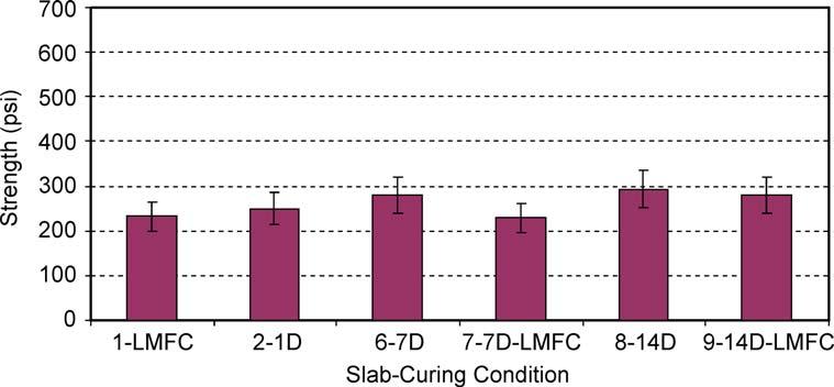
18 F1-Low 9/6-22/ %RH T of /07/ /08/ /09/ /10/ /11/ /12/ /13/ /14/ /15/ /16/ /17/ /18/ /19/ /20/ /21/ /22/2006 Figure 12. Temperature and Relative Humidity Data for Block F1, 3 in Below Surface Coring for tests at an age of 3 months was limited to two or three slabs. For Batches A through F, three slabs were cored: Slab 1 (), Slab 6 (7-day wet), and Slab 7 (7-day wet- ). For Batches G through I, two slabs were cored: Slab 1 () and Slab 3 (3-day wet). Two-inch-diameter core bits were drilled into these slabs at two depths for pull-off testing to determine the tensile strength of the concrete. The results are shown in Figures 13 and 14 for 5/8-in and 3-in depths, respectively. The error bars represent the repeatability range (29%) based on the pooled coefficient of variation (10.2%) for the pull-off tests in this study. At the 5/8-in depth (Figure 13), the 0.45 w/cm mixtures tended to show higher tensile strength with wet curing in contrast to the 0.35 w/cm mixtures. With Batches D and E, the 7-day wet- was considerably lower than the other curing conditions for these batches, but these may simply be outliers. Overall strengths were generally lower for the 3-in depths. The condition for the 0.45 w/cm Batch A at 5/8-in depth was significantly lower than the corresponding wet cured conditions, in contrast to its corresponding 0.35 w/cm Batch D. One-year tensile strengths at 3-in depth were obtained for selected blocks of all batches and are presented in Figures 15 through 23. No clear trend emerges with respect to the impact curing condition on tensile strength from these results. Although certain values stand out, in particular, the Slab 7 7-day for Batch B, the high value for this curing condition was not borne out in other batches such as Batch D (same w/cm) or E (also slag cement), so the value appears to represent an aberrant value. Likely, the 3-in depth is beyond the influence of surface curing. 13


19 Figure 13. Three-Month Pull-Off Tensile Strength at 5/8-in Depth for Batches A Through I. The repeatability range is 29%. Figure 14. Three-Month Pull-Off Tensile Strength at 3-in Depth for Batches A-I. The repeatability range is 29%. 14


20 Figure 15. Tensile Strength at 3-in Depth for Selected Slabs, Batch A. The repeatability range is 29%. Figure 16. Tensile Strength at 3-in Depth for Selected Slabs, Batch B. The repeatability range is 29%. Figure 17. Tensile Strength at 3-in Depth for Selected Slabs, Batch C. The repeatability range is 29%. 15

21 Figure 18. Tensile Strength at 3-in Depth for Selected Slabs, Batch D. The repeatability range is 29%. Figure 19. Tensile Strength at 3-in Depth for Selected Slabs, Batch E. The repeatability range is 29%. Figure 20. Tensile Strength at 3-in Depth for Selected Slabs, Batch F. The repeatability range is 29%. 16


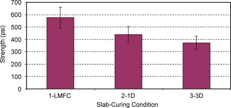
22 Figure 21. Tensile Strength at 3-in Depth for Selected Slabs, Batch G. The repeatability range is 29%. Figure 22. Tensile Strength at 3-in Depth for Selected Slabs, Batch H. The repeatability range is 29%. Figure 23. Tensile Strength at 3-in Depth for Selected Slabs, Batch I. The repeatability range is 29%. 17
23 The lack of a dramatic impact of length of moist curing on strength in these tests may seem surprising. Conventional wisdom holds that the longer the moist curing, the better particularly for HPCs with pozzolans or slag cement and/or with low w/cm. However, certain aspects of the findings with regard to strength are similar to those reported by Carino and Meeks (2001) who found 1 day of moist curing likely sufficient for HPC. Their study examined mortars at 0.30 and 0.45 w/cm, moist cured for 1, 3, or 7 days followed by drying from one surface at 50% or 70% RH and compared to continuous moist curing. Tensile testing was performed at 28 days. They noted a potential confounding influence on strength measurement that drying may have because of physical aspects that result in increased strength. However, they indicated that the drying front did not progress much beyond ½ in with deeper penetrations associated with lower RH and higher w/cm. Likewise, they found a large decrease in moisture loss after 5 days of drying for 0.45 w/cm specimens that had been moist cured for 3 days as opposed to 1 day but only a subtle effect from extending moist curing to 7 days. For the 0.30 w/cm mortars, the moist curing duration effect on moisture loss was only subtle. Carino and Meeks (2001) drew from this and much earlier work (Powers et al., 1959) that the benefit to durability of longer duration moist curing increases with increasing w/cm. Comparisons used to support extended moist curing are often referenced between continuous moist curing and indoor drying conditions at constant low humidity. This study contrasts a range of moist curing conditions that are being applied to bridge decks (up to 14 days) followed by outdoor environmental exposure over an extended period. As such, the results of this study are likely more relevant to actual field practices in similar climatic regions. The 1-year electrical conductivity results for cores removed from selected slabs are shown in Figures 24 through 32. Conductivities were measured on specimens retrieved from two depths below the surface of the slab: 0 through 2 in and 3 through 5 in. The conductivity values for Batch A (PC, 0.45 w/cm) were considerably higher than for the other batches, as is typical for straight portland cement concrete at this w/cm. For Batch D (PC 0.35 w/cm), the conductivities were considerably lower and nearly on par with the conductivities of mixtures containing pozzolans or slag cement. Batch D conductivities were lowest for the and 1- day wet curing conditions, both near-surface and at-depth. For Batch F, the near surface conductivities tended to increase with increasing wet curing duration, but the conductivities at depth were constant across curing conditions. For the remaining batches, conductivities both near-surface and at-depth were low and did not show a consistent trend with increasing wet curing duration. Batches B and C near-surface conductivities were reduced by the 1-day wet curing over the conditions, but beyond that, differences in curing exhibited little impact. The initial and secondary sorptivities for cores removed from selected slabs at 1 year are shown in Figures 33 through 41. The initial sorptivity is a function of the rate of absorption over the initial 6-hour period. The secondary sorptivity is the longer-term rate of absorption extending from 6 hours over several days (Lane, 2006b). Typically in concretes with good transport characteristics, the initial sorptivity will be higher than the secondary sorptivity, indicating a closing-off of the capillary pore system (Martys and Ferraris, 1997), suggesting that the secondary rate may be of more significance with respect to long-term durability than the initial rate. As points of reference, Lane (2006a) reported values of 20 x 10-4 and 10 x

24 mm/s 1/2, respectively, for initial and secondary sorptivity as desirable upper limits based on a survey of mature bridge decks. Figure Year Electrical Conductivity at Depths of 0-2 in and 3-5 in Below Surface for Selected Curing Conditions, Batch A. The repeatability range is 14%. Figure Year Electrical Conductivity at Depths of 0-2 in and 3-5 in Below Surface for Selected Curing Conditions, Batch B. The repeatability range is 14%. 19
25 Figure Year Electrical Conductivity at Depths of 0-2 in and 3-5 in Below Surface for Selected Curing Conditions, Batch C. The repeatability range is 14%. Figure Year Electrical Conductivity at Depths of 0-2 in and 3-5 in Below Surface for Selected Curing Conditions, Batch D. The repeatability range is 14%. 20
26 Figure Year Electrical Conductivity at Depths of 0-2 in and 3-5 in Below Surface for Selected Curing Conditions, Batch E. The repeatability range is 14%. Figure Year Electrical Conductivity at Depths of 0-2 in and 3-5 in Below Surface for Selected Curing Conditions, Batch F. The repeatability range is 14%. 21
27 Figure Year Electrical Conductivity at Depths of 0-2 in and 3-5 in Below Surface for Selected Curing Conditions, Batch G. The repeatability range is 14%. Figure Year Electrical Conductivity at Depths of 0-2 in and 3-5 in Below Surface for Selected Curing Conditions, Batch H. The repeatability range is 14%. 22
28 Figure Year Electrical Conductivity at Depths of 0-2 in and 3-5 in Below Surface for Selected Curing Conditions, Batch I. The repeatability range is 14%. Sorptivities were originally measured at 1 year following standard conditioning at 80% RH. The initial sorptivity values for Batch C (Figure 35) showed a precipitous drop between the 14-day and 14-day- conditions that raised concern that a systematic error had occurred. A likely cause for the disparate results was that specimens were not brought to similar internal RH conditions; e.g., a nearly saturated specimen will yield much lower sorptivity values that one in which the capillary pore systems have dried to a substantial extent. Consequently, the specimens were allowed to equilibrate in the laboratory atmosphere for 4 months and then retested. Following the retesting of all Batch C specimens, the near-surface specimens for the other batches were retested. Because of the differences in conditioning, direct comparisons between the 1-year and 1-year-4M values should not be made. Following the retesting of the Batch C specimens, the large disparity in results apparently related to curing did not occur. Although the initial sorptivity results do not present a dramatic impact of wet curing duration on this property, there does seem to be at least a subtle positive influence of at least 1- day through 3-day wet curing over simple in Batches A (Figure 33), B (Figure 34), E (Figure 37), G (Figure 39), and H (Figure 40), but there seemed to be little or no impact provided by the use of following moist curing. These effects are not apparent in the secondary sorptivity results. The biggest influence on sorptivity in these concretes was w/cm, where both initial and secondary sorptivities were much lower for the concretes with 0.35 w/cm (Batches D, F, G, H, and I) than for those with 0.45 w/cm (Batches A and C). The notable exceptions to this trend were Batches B (0.35 w/cm) and E (0.45 w/cm), the two slag cement concretes. Comparing the results for these two batches, the initial sorptivities were fairly similar, and both showed minimal values for 1-day wet curing. Powers et al. (1959) noted the strong influence of w/c on the continuity of the pore system and estimated necessary moist curing durations of 7 days for 0.45 w/c and 3 days for 0.40 w/c pastes to achieve a discontinuous capillary system. 23
29 Initial Sorptivity Batch A in depth 3-5 in depth mm/s 1/2 x Y 1Y-4m Curing condition Secondary Sorptivity Batch A in depth 3-5 in depth mm/s 1/2 x Y 1Y-4M Curing condition Figure Year + Initial and Secondary Sorptivity at Selected Curing Conditions, Batch A. The repeatability range is 26%. 24
30 Initial Sorptivity Batch B in depth 3-5 in depth mm/s 1/2 x Y 1Y-4m Curing condition Secondary Sorptivity Batch B in depth 3-5 in depth mm/s 1/2 x Y 1Y-4M Curing condition Figure Year + Initial and Secondary Sorptivity at Selected Curing Conditions, Batch B. The repeatability range is 26%. 25
31 Initial Sorptivity Batch C in depth 3-5 in depth mm/s 1/2 x Y 1Y-4m Curing condition Secondary Sorptivity Batch C in depth 3-5 in depth mm/s 1/2 x Y 1Y-4m Curing condition Figure Year + Initial and Secondary Sorptivity at Selected Curing Conditions, Batch C. The repeatability range is 26%. 26
32 Initial Sorptivity Batch D in depth 3-5 in depth mm/s 1/2 x Y 1Y-4m Curing condition Secondary Sorptivity Batch D 0-2 in depth 3-5 in depth mm/s 1/2 x Y 1Y-4M Curing condition Figure Year + Initial and Secondary Sorptivity at Selected Curing Conditions, Batch D. The repeatability range is 26%. 27
33 Initial Sorptivity Batch E in depth 3-5 in depth mm/s 1/2 x Y 1Y-4m Curing condition Secondary Sorptivity Batch E in depth 3-5 in depth mm/s 1/2 x Y 1Y-4M Curing condition Figure Year + Initial and Secondary Sorptivity at Selected Curing Conditions, Batch E. The repeatability range is 26%. 28
34 Initial Sorptivity Batch F in depth 3-5 in depth mm/s 1/2 x Y 1Y-4m Curing condition Secondary Sorptivity Batch F in depth 3-5 in depth mm/s 1/ Y 1Y-4M Curing condition Figure Year + Initial and Secondary Sorptivity at Selected Curing Conditions, Batch F. The repeatability range is 26%. 29
35 Initial Sorptivity Batch G in depth 3-5 in depth mm/s 1/2 x Y 1Y-4m D 3D Curing condition Secondary Sorptivity Batch G 0-2 in depth 3-5 in depth mm/s 1/2 x Y 1Y-4M D 3D Curing condition Figure Year + Initial and Secondary Sorptivity at Selected Curing Conditions, Batch G. The repeatability range is 26%. 30
36 Initial Sorptivity Batch H in depth 3-5 in depth mm/s 1/2 x Y-4m 1Y-4m D 3D Curing condition mm/s 1/2 x Secondary Sorptivity Batch H 0-2 in depth 3-5 in depth 3D 3D Curing condition 1Y 1Y-4M Figure Year + Initial and Secondary Sorptivity at Selected Curing Conditions, Batch H. The repeatability range is 26%. 31
37 mm/s 1/2 x Initial Sorptivity Batch I 0-2 in depth 3-5 in depth 3D 3D Curing condition 1-Y 1Y-4m mm/s 1/2 x Secondary Sorptivity Batch I 0-2 in depth 3-5 in depth 3D 3D Curing condition 1Y 1Y-4M Figure Year + Initial and Secondary Sorptivity at Selected Curing Conditions, Batch I. The repeatability range is 26%. 32
38 Examination of thin sections revealed a fair amount of cracking in the slag cement concretes (Figures 42 through 45), which likely explains the relatively high initial sorptivities for these concretes. The slag concretes did, however, also contain residual unhydrated slag cement particles (Figure 45) that can continue to hydrate provided sufficient moisture is present. The prospect for this appears good based on the apparent high moisture content of the slabs and from examinations of mature bridge deck concretes containing slag cement where sorptivities generally were low (Lane, 2006a), but continued monitoring of these slabs or actual bridge decks containing slag cement should be carried out to confirm their ability to provide low transport properties in the long term. The observation of unhydrated remnants of grains of cementitious materials is to be expected in concretes of this general quality. Figures 46 and 47 show unhydrated fly ash and silica fume agglomerate, respectively. Ideally the silica fume agglomerate would have been broken into the much finer individual particulates, dispersed, and hydrated. Often, a lack of unhydrated particles of portland cement, fly ash, or slag cement is a sign of high w/cm. For instance, Powers et al. (1959) reported that 100% hydration of cement was necessary to achieve discontinuity in the capillary system of a paste at 0.7 w/c; only 70% hydration was needed at 0.5 w/c. Although severe early drying could result in an excessive amount of unhydrated cementitious material, the general properties of these concretes and the observations regarding RH do not support a conclusion that that occurred. The relatively high sorptivities for the slag cement concretes (Batches B and E) stand in contrast to their low electrical conductivity (Figures 25 and 28). This feeds a recurring question of the meaningfulness of the electrical measures of concrete transport properties, particularly for mature concretes. Lane (2006a) reported low electrical conductivity for many bridge deck concretes that stood in contrast to their high initial and secondary sorptivities. Similarly, Ozyildirim and Halstead (1992) reported data for bridge deck concretes showing little correspondence between electrical charge passed in coulombs (AASHTO T 277, ASTM C 1202) and chloride penetration. Similar to the findings of the pull-off strength tests, the results of the electrical conductivity and sorptivity tests do not show a systematic improvement of transport properties of the concrete tied to increasing duration of wet curing. At best, a case might be made for 1-day through 3-day wet curing as being slightly preferable to simple. This should not be taken to imply that curing is not important for durability properties, but rather that all of the curing regimes evaluated appear more or less adequate for the weather conditions (warm, humid) during and after placement. It should also be kept in mind that regardless of what curing practice is followed, it is important to prevent drying of the concrete surface between finishing and the curing application. Further, there appears to be no impact related to following wet curing with an application of. The rationale for this practice has been that it will slow drying and thus result in slower stress development as the surface dries, thus lessening the potential for cracking. The weather conditions following cessation of wet curing may determine whether an application of is necessary to slow drying. If the prevailing air mass for the days following the curing period will be dry, conceptually there may be some benefit to the application. On the other hand, if humid conditions will prevail, as was the case in this study, then little benefit 33

, Slab 2 (1-day wet) Near Surface Showing Crack Through Paste Figure 43.")
39 would likely be observed. As it seems that atmospheric conditions during and after placement and curing periods may impact what practices are necessary, construction personnel and engineers should pay close attention to these conditions and plan and execute curing practices accordingly. Figure 42. Thin Section of Batch B (slag cement, 0.35 w/cm), Slab 2 (1-day wet) Near Surface Showing Crack Through Paste Figure 43. Thin Section of Batch B (slag cement, 0.35 w/cm), Slab 7 (7-day wet-) Near Surface Showing Crack Through Paste 34
, Slab 1 () Near Surface Showing Crack Through Paste.")

40 Figure 44. Thin Section of Batch E (slag cement, 0.45 w/cm), Slab 1 () Near Surface Showing Crack Through Paste. Box outlines field of view in Figure 44. Figure 45. Thin Section of Batch E (slag cement, 0.45 w/cm), Slab 1 () Near Surface Showing Crack Through Paste. S indicates unhydrated portions of slag cement particles. 35
, Slab 3 (3-day wet) Near Surface Showing Largely Unhydrated Fly Ash Particle")

41 Figure 46. Thin Section of Batch G (fly ash, 0.35 w/cm, LWFA), Slab 3 (3-day wet) Near Surface Showing Largely Unhydrated Fly Ash Particle (middle right). Several cement grains with unhydrated cores are present. Figure 47. Thin Section of Batch H (silica fume, 0.35 w/cm, LWFA), Slab 3 (3-day wet) Near Surface Showing Largely Unhydrated Silica Fume Agglomerate (middle). 36
research report Laboratory Comparison of Several Tests for Evaluating the Transport Properties of Concrete Virginia Transportation Research Council
 Final Report VTRC 06-R38 Virginia Transportation Research Council research report Laboratory Comparison of Several Tests for Evaluating the Transport Properties of Concrete http:/www.virginiadot.org/vtrc/main/online_reports/pdf/06-r38.pdf
Experimental Case Study Demonstrating Advantages of Performance Specifications Karthik Obla 1 Fernando Rodriguez 2 and Soliman Ben Barka 3
 Experimental Case Study Demonstrating Advantages of Performance Specifications Karthik Obla 1 Fernando Rodriguez 2 and Soliman Ben Barka 3 NRMCA is working on an initiative to evolve specifications from
NRMCA is working on. Experimental Case Study Demonstrates Advantages of Performance Specifications
 Experimental Case Study Demonstrates Advantages of Performance Specifications By Karthik Obla, Director of Research and Materials Engineering Fernando Rodriguez, Laboratory Manager and Soliman Ben Barka,
Reed, Hale 1. Slag Cement Concrete for Use in Bridge Decks. August 1, Words (6 Tables = 1500 words)
") Reed, Hale 1 1 2 3 4 5 6 7 8 9 10 11 12 13 14 15 16 17 18 19 20 21 22 23 24 25 26 27 28 29 30 31 32 33 34 35 36 37 38 39 40 41 42 43 44 45 46 Slag Cement Concrete for Use in Bridge Decks August 1, 2011
Reed, Hale 1 1 2 3 4 5 6 7 8 9 10 11 12 13 14 15 16 17 18 19 20 21 22 23 24 25 26 27 28 29 30 31 32 33 34 35 36 37 38 39 40 41 42 43 44 45 46 Slag Cement Concrete for Use in Bridge Decks August 1, 2011
FINAL REPORT EVALUATION OF HYDRAULIC CEMENT CONCRETE OVERLAYS PLACED ON THREE PAVEMENTS IN VIRGINIA. Michael M. Sprinkel, P.E.
 FINAL REPORT EVALUATION OF HYDRAULIC CEMENT CONCRETE OVERLAYS PLACED ON THREE PAVEMENTS IN VIRGINIA Michael M. Sprinkel, P.E. Research Manager Celik Ozyildirim, Ph.D. Principal Research Scientist (The
DEVELOPMENT OF A SPECIFICATION FOR LOW CRACKING BRIDGE DECK CONCRETE IN VIRGINIA
 DEVELOPMENT OF A SPECIFICATION FOR LOW CRACKING BRIDGE DECK CONCRETE IN VIRGINIA Virginia DOT Workshop Charlottesville, VA Harikrishnan Nair, Ph.D., P.E, VTRC Senior Research Scientist October 4, 2017
PERFORMANCE-RELATED SPECIAL PROVISION FOR HIGH PERFORMANCE CONCRETE MIX DESIGNS FOR CONCRETE SUPERSTRUCTURE (Tollway)
") PERFORMANCE-RELATED SPECIAL PROVISION FOR HIGH PERFORMANCE CONCRETE MIX DESIGNS FOR CONCRETE SUPERSTRUCTURE (Tollway) Effective: October 12, 2012 Revised: June 14, 2013 DESCRIPTION This work consists of
PERFORMANCE-RELATED SPECIAL PROVISION FOR HIGH PERFORMANCE CONCRETE MIX DESIGNS FOR CONCRETE SUPERSTRUCTURE (Tollway) Effective: October 12, 2012 Revised: June 14, 2013 DESCRIPTION This work consists of
Lane 1 PERFORMANCE OF SLAG CEMENT IN VIRGINIA CONCRETES
 Lane PERFORMANCE OF SLAG CEMENT IN VIRGINIA CONCRETES D. Stephen Lane Associate Principal Research Scientist Phone: -- Email: Stephen.Lane@vdot.virginia.gov Virginia Center for Transportation Innovation
Optimizing Concrete Mixtures for Performance and Sustainability
 Optimizing Concrete Mixtures for Performance and Sustainability Prepared by: Karthik Obla, Ph.D., P.E. Colin Lobo, Ph.D., P.E. Rongjin Hong National Ready Mixed Concrete Association Silver Spring, MD Haejin
Experimental Case Study Demonstrating Advantages of Performance Specifications
 RMC Research Foundation Experimental Case Study Demonstrating Advantages of Performance Specifications Prepared by: Karthik Obla, PhD, PE Colin Lobo, PhD, PE Experimental Case Study Demonstrating Advantages
Investigation of the Long Term Effects of Magnesium Chloride and Other Concentrated Salt Solutions on Pavement and Structural Portland Cement Concrete
 Investigation of the Long Term Effects of Magnesium Chloride and Other Concentrated Salt Solutions on Pavement and Structural Portland Cement Concrete Project Number: SD2002-01 Submitted by: Lawrence L.
Overlays. HCC Deck Overlays. Key Decisions for Concrete Deck Overlays
 Key Decisions for Concrete Deck Overlays Virginia Concrete Conference March 7, 2007 Michael Sprinkel, P.E. Associate Director Virginia Transportation Research Council Overlays Overlays are usually placed
SECTION 434 HIGH PERFORMANCE CONCRETE (HPC)
") SECTION 434 HIGH PERFORMANCE CONCRETE (HPC) 434.01 DESCRIPTION. This work shall consist of the construction of portland cement concrete deck slabs, headblocks, bridge sidewalks, unsurfaced bridge approach
SECTION 434 HIGH PERFORMANCE CONCRETE (HPC) 434.01 DESCRIPTION. This work shall consist of the construction of portland cement concrete deck slabs, headblocks, bridge sidewalks, unsurfaced bridge approach
Understanding its Effects on Coatings MOISTURE IN CONCRETE. VersaFlex. Copyright 2008 I N C O R P O R A T E D
 Understanding its Effects on Coatings MOISTURE IN CONCRETE Copyright 2008 Moisture, ph and Alkalies Freshly placed Portland Cement ph 12.5 Provides passivation of embedded steel Carbon Dioxide and ambient
TACAMP 2014 CONCRETE. Presented by Rick Wheeler
 TACAMP 2014 CONCRETE Presented by Rick Wheeler HISTORY OF CONCRETE 2000 years and still working Concrete is the longest lasting Man-made construction material The Roman Pantheon is the largest (43.4m dia.)
Pumice Pozz vs. Fly Ash
 Pumice Pozz vs. Fly Ash Extensive ASTM-standard Research Quantifies Pumice as the Ideal Replacement for Fly Ash in Concrete IN EACH AND EVERY ONE of the concrete performance categories that matter, clean,
Investigation of Properties of High-Performance Fiber- Reinforced Concrete: Very Early Strength, Toughness, Permeability, and Fiber Distribution
 Investigation of Properties of High-Performance Fiber- Reinforced Concrete: Very Early Strength, Toughness, Permeability, and Fiber Distribution http://www.virginiadot.org/vtrc/main/online_reports/pdf/17-r3.pdf
Fundamentals of Concrete
 Components Cement Water Fine Aggregate Coarse Aggregate Fundamentals of Range in Proportions Advantages of Reducing Water Content: Increased strength Lower permeability Fundamentals of Increased resistance
MICHIGAN CONCRETE ASSOCIATION GUIDE FOR COLD WEATHER CONCRETING
 MICHIGAN CONCRETE ASSOCIATION GUIDE FOR COLD WEATHER CONCRETING MCA:SMW 1 of 6 10-25-11 For the purposes of this document and the MCA Special Provision for Cold Weather Concreting, cold weather is determined
VDOT s New High Performance Concrete Specifications
 VDOT s New High Performance Concrete Specifications Celik Ozyildirim, Ph.D., P.E. A partnership of the Virginia Department of Transportation and the University of Virginia since 1948 3/4/2010 1 HPC in
Bridge Beams and Pier Caps With Self-Consolidating Concrete at Nimmo Parkway
 Bridge Beams and Pier Caps With Self-Consolidating Concrete at Nimmo Parkway http://www.virginiadot.org/vtrc/main/online_reports/pdf/16-r11.pdf CELIK OZYILDIRIM, Ph.D., P.E. Principal Research Scientist
Polymer Overlays of New Bridge Decks. Kyle Riding, Ph.D., P.E. Robert J. Peterman, Ph.D., P.E. Andy Shearrer
 Polymer Overlays of New Bridge Decks Kyle Riding, Ph.D., P.E. Robert J. Peterman, Ph.D., P.E. Andy Shearrer Kansas Polymer Overlays Epoxy Polymer Overlays 2 part epoxy Flint aggregate Epoxy protects the
A. Section includes cast-in-place concrete, including reinforcement, concrete materials, mixture design, placement procedures, and finishes.
 SECTION 033053 - CONCRETE PART 1 - GENERAL 1.1 RELATED DOCUMENTS A. Drawings and general provisions of the Contract, including General and Supplementary Conditions and Division 01 Specification Sections,
FINAL REPORT LOW-PERMEABILITY CONCRETES CONTAINING SLAG AND SILICA FUME. Celik Ozyildirim, Ph.D. Senior Research Scientist
 FINAL REPORT LOW-PERMEABILITY CONCRETES CONTAINING SLAG AND SILICA FUME Celik Ozyildirim, Ph.D. Senior Research Scientist (The opinions, findings, and conclusions expressed in this report are those ofthe
Frequently Asked Questions (FAQ s) about Concrete Driveways
 about Concrete Driveways") Frequently Asked Questions (FAQ s) about Concrete Driveways What type of concrete mix should be used? Your local ready mix producer and your contractor will assist you in ensuring the proper concrete mix
Frequently Asked Questions (FAQ s) about Concrete Driveways What type of concrete mix should be used? Your local ready mix producer and your contractor will assist you in ensuring the proper concrete mix
Specifying Concrete for Durability Performance-Based Criteria Offer Best Solutions Karthik Obla, Colin Lobo, Lionel Lemay NRMCA
 Specifying Concrete for Durability Performance-Based Criteria Offer Best Solutions Karthik Obla, Colin Lobo, Lionel Lemay NRMCA Introduction A specification for concrete construction is a set of instructions
EVALUATION OF DURABILITY OF ODOT PRESTRESSED/PRECAST CONCRETE IN OHIO
 EVALUATION OF DURABILITY OF ODOT PRESTRESSED/PRECAST CONCRETE IN OHIO BY NICK SCAGLIONE, PRESIDENT CONCRETE RESEARCH & TESTING, LLC 400 FRANK ROAD COLUMBUS, OHIO 43207 SEPTEMBER 2002 PREPARED FOR THE OHIO
DIVISION II CONSTRUCTION AND MATERIAL SPECIFICATIONS SECTION 2700 STRUCTURES
 DIVISION II CONSTRUCTION AND MATERIAL SPECIFICATIONS SECTION 2700 STRUCTURES APPROVED AND ADOPTED THIS 23RD DAY OF MAY 2001 KANSAS CITY METROPOLITAN CHAPTER OF THE AMERICAN PUBLIC WORKS ASSOCIATION 2701
CHAPTER 3 MATERIAL PROPERTIES AND MIX PROPORTIONS
 45 CHAPTER 3 MATERIAL PROPERTIES AND MIX PROPORTIONS 3.1 GENERAL In the present investigation, it was planned to cast M40 & M50 grade concrete with and without supplementary cementitious material such
BORAL MICRON 3 WORKABILITY, SHRINKAGE CRACK RESISTANCE, AND HIGH STRENGTH CONCRETE
 Workability reduces water and high range water reducing (HRWR) admixture demand and improves concrete workability. This is in contrast to most highly reactive pozzolans. Figure 1 is a summary of the water
SECTION CAST IN PLACE CONCRETE FOR FLOOR SLABS ON GRADE THAT WILL RECEIVE SEMI-PERMEABLE OR IMPERMEABLE FLOOR FINISHES
 GUIDE SPECIFICATION SECTION CAST IN PLACE CONCRETE FOR FLOOR SLABS ON GRADE THAT WILL RECEIVE SEMI-PERMEABLE OR IMPERMEABLE FLOOR FINISHES PART 1 - SCOPE 1.01 WORK INCLUDED: 1.1.1 This guide covers the
Nelson Testing Laboratories
 in Elmhurst, Illinois, USA has demonstrated proficiency for the testing of construction materials and has conformed to the requirements established in AASHTO R 18 and the AASHTO Accreditation policies
Hot Weather Concreting
 Hot Weather Concreting Presented by: Tom Pelo Area Sales Leader BASF Construction Chemicals Admixture Division ACI 305 Definition of Hot Weather Any combination of high ambient temperature, high concrete
AASHTO/NTPEP Rapid Set Concrete Patching Materials
 AASHTO/NTPEP Rapid Set Concrete Patching Materials User Guide 2015 Introduction: The National Transportation Product Evaluation Program (NTPEP) was established to minimize the amount of duplicative testing
Effect of Wet-Mat Curing Time and Earlier Loading on Long-Term Durability of Bridge Decks: Executive Summary
 Effect of Wet-Mat Curing Time and Earlier Loading on Long-Term Durability of Bridge Decks: Executive Summary by Sanjaya Senadheera Phillip T. Nash Research Report Number 0-2116-6 Research Project Number
FINAL CONTRACT REPORT EVAULATION OF MODELS FOR PREDICTING (TOTAL) CREEP OF PRESTRESSED CONCRETE MIXTURES
 CREEP OF PRESTRESSED CONCRETE MIXTURES") FINAL CONTRACT REPORT EVAULATION OF MODELS FOR PREDICTING (TOTAL) CREEP OF PRESTRESSED CONCRETE MIXTURES Richard Meyerson, Graduate Research Assistant Richard E. Weyers, Charles E. Via, Jr. Professor Charles
FINAL CONTRACT REPORT EVAULATION OF MODELS FOR PREDICTING (TOTAL) CREEP OF PRESTRESSED CONCRETE MIXTURES Richard Meyerson, Graduate Research Assistant Richard E. Weyers, Charles E. Via, Jr. Professor Charles
Experimental Installation of a Concrete Bridge-Deck Overlay Containing Silica Fume
 36 TRANSPORTATION RESEARCH RECORD 1204 Experimental Installation of a Concrete Bridge-Deck Overlay Containing Silica Fume CELIK 0ZYILDIRIM This popcr summarizes the experimental installation of a concrete
KANSAS DEPARTMENT OF TRANSPORTATION SPECIAL PROVISION TO THE STANDARD SPECIFICATIONS, 2015 EDITION
 Sheet 1 of 5 KANSAS DEPARTMENT OF TRANSPORTATION SPECIAL PROVISION TO THE STANDARD SPECIFICATIONS, 2015 EDITION Delete SECTION 403 and replace with the following: SECTION 403 ON GRADE CONCRETE 403.1 DESCRIPTION
Laboratory Assessment of Drying Shrinkage of Concretes Containing Shrinkage Reducing Agents Compared with a New Low shrinkage Concrete
 Laboratory Assessment of Drying Shrinkage of Concretes Containing Shrinkage Reducing Agents Compared with a New Low shrinkage Concrete Bob Bornstein, Tony Song 2, and Valentin Mukhin 3 Manager Technical
VIRGINIA S EXPERIENCE WITH HPC FOR BRIDGES. Outline HPC. Celik Ozyildirim, Ph.D., P.E. Virginia Transportation Research Council VDOT
 VIRGINIA S EXPERIENCE WITH HPC FOR BRIDGES Celik Ozyildirim, Ph.D., P.E. Virginia Transportation Research Council VDOT Virginia Concrete Conference, March 7, 2007 Outline HPC Field applications Lessons
Doç. Dr. Halit YAZICI. D. E. U. Civil Engineering Department.
 Doç. Dr. Halit YAZICI D. E. U. Civil Engineering Department http://kisi.deu.edu.tr/halit.yazici Chemical Admixtures In Concrete What Are They? Ingredients other than: Cement Water Aggregates Added before
Rapid Repair Materials and Construction Rapid Bridge Repair Workshop Holiday Inn Tanglewood-Roanoke, Virginia May 21 and 22, 2009
 Rapid Repair Materials and Construction Rapid Bridge Repair Workshop Holiday Inn Tanglewood-Roanoke, Virginia May 21 and 22, 2009 Michael Sprinkel, P.E. Associate Director Virginia Transportation Research
Comparison of Properties of Fresh and Hardened Concrete Containing Finely Ground Glass Powder, Fly Ash, or Silica Fume
 Article Comparison of Properties of Fresh and Hardened Concrete Containing Finely Ground Glass Powder, Fly Ash, or Silica Fume Rungrawee Wattanapornprom a, and Boonchai Stitmannaithum b Faculty of Engineering,
Wiss, Janney, Elstner Associates, Inc.
 in Northbrook, Illinois, USA has demonstrated proficiency for the testing of construction materials and has conformed to the requirements established in AASHTO R 18 and the AASHTO Accreditation policies
Evaluation of the Compressive Strength and Rapid Chloride Permeability of High Replacement Ternary Mixtures
 Rupnow Evaluation of the Compressive Strength and Rapid Chloride Permeability of High Replacement Ternary Mixtures Submission Date: -- By: T. D. Rupnow Tyson D. Rupnow (Corresponding Author) Louisiana
PERFORMANCE EVALUATION OF CORROSION INHIBITORS AND GALVANIZED STEEL IN CONCRETE EXPOSURE SPECIMENS
 FINAL CONTRACT REPORT PERFORMANCE EVALUATION OF CORROSION INHIBITORS AND GALVANIZED STEEL IN CONCRETE EXPOSURE SPECIMENS J ERZY ZEMAJTIS Research Associate Virginia Polytechnic Institute and State University
Hydrophilic Crystalline Waterproofing of Concrete-Admixture
 Hydrophilic Crystalline Waterproofing of Concrete-Admixture Kryton International Inc. SECTION 03305 Hydrophilic Crystalline Waterproofing of Concrete Admixture PART 1 GENERAL 1.1 SECTION INCLUDES - A.
Premature Failure of Concrete Patching: Reasons and Resolutions
 Premature Failure of Concrete Patching: Reasons and Resolutions http://www.virginiadot.org/vtrc/main/online_reports/pdf/19-r14.pdf MICHAEL M. SPRINKEL, P.E. Associate Director M. SHABBIR HOSSAIN, Ph.D.,
INTEGRALLY COLORED CONCRETE [DECORATIVE CONCRETE PAVING]
![INTEGRALLY COLORED CONCRETE [DECORATIVE CONCRETE PAVING]](/thumbs/95/122592868.jpg "INTEGRALLY COLORED CONCRETE [DECORATIVE CONCRETE PAVING]") Note to Specifier: The Admixture Systems business of BASF Corporation previously conducted business as Degussa Admixtures, Inc. and Master Builders, Inc. BASF has launched the Master Builders Solutions
Note to Specifier: The Admixture Systems business of BASF Corporation previously conducted business as Degussa Admixtures, Inc. and Master Builders, Inc. BASF has launched the Master Builders Solutions
VARIATION OF CONCRETE STRENGTH, PERMEABILITY, AND POROSITY DUE TO SPECIMEN TYPE, SEASON, AND AGE
 VARIATION OF CONCRETE STRENGTH, PERMEABILITY, AND POROSITY DUE TO SPECIMEN TYPE, SEASON, AND AGE By Matthew O Reilly David Darwin Jayne Sperry JoAnn Browning A Report on Research Sponsored by The Kansas
Study and Analysis of High Performance Concrete and Estimation of Concrete Strength
 Study and Analysis of High Performance Concrete and Estimation of Concrete Strength 1 Swapnil Bhoir, 2 Nilam Adsul, 3 Shrikant Charhate 1,2,3 Dept. of Civil Engineering Abstract --The present day world
Performance Engineered Mixtures So what
 Performance Engineered Mixtures So what 1 An Emphasis on Durability What do I want? How do I get what I want with what I have? How do I know? What Do We Want? The pavement owner wants: Strong enough Crack
Chapter 6: Admixtures for Concrete
 Chapter 6: Admixtures for Concrete Definition A material other than water, aggregates and hydraulic cement that is used as an ingredient in concrete or mortar and is added to the batch immediately before
Effects of Materials and Mixing Procedures on Air Void Characteristics of Fresh Concrete
 Effects of Materials and Mixing Procedures on Air Void Characteristics of Fresh Concrete Shihai Zhang Civil, Construction and Environmental Engineering Iowa State University 16 Town Engineering Building
Admixtures-Section 924
 Admixtures-Section 924 - Qualified Products List - Types include: - Air Entraining - Water-Reducing (Type A) - Accelerating (Type C) - Water-Reducing & Retarding (Type D) - Water-Reducer & Accelerating
Prediction of Chloride Permeability of High Performance Concrete
 Prediction of Chloride Permeability of High Performance Concrete M. Iqbal KHAN Saleh ALSAYED Assistant Professor Professor King Saud University King Saud University Riyadh 1141, KSA Riyadh 1141, KSA Summary
Lowering the Carbon Footprint of Concrete by Reducing the Clinker Content of Cement
 Lowering the Carbon Footprint of Concrete by Reducing the Clinker Content of Cement Michael Thomas, University of New Brunswick Ken Kazanis, Kevin Cail, Anik Delagrave, Bruce Blair, Lafarge North America
Evaluation of Bridge Deck With Shrinkage- Compensating Concrete
 Evaluation of Bridge Deck With Shrinkage- Compensating Concrete http://www.virginiadot.org/vtrc/main/online_reports/pdf/16-r15.pdf HARIKRISHNAN NAIR, Ph.D., P.E. Research Scientist CELIK OZYILDIRIM, Ph.D.,
I-64 DUNLAP CREEK BRIDGE REHABILITATION JOINTLESS BRIDGES, DECK OVERLAYS, AND CONCRETE MATERIALS
 I-64 DUNLAP CREEK BRIDGE REHABILITATION JOINTLESS BRIDGES, DECK OVERLAYS, AND CONCRETE MATERIALS June 8, 2016 Celik Ozyildirim, PhD, PE, Principal Research Scientist, VTRC, Charlottesville, VA Rex Pearce,
Nair, Ozyildirim, and Sprinkel 1 REDUCING CRACKS IN CONCRETE BRIDGE DECKS USING SHRINKAGE REDUCING ADMIXTURE
 Nair, Ozyildirim, and Sprinkel 0 0 0 0 REDUCING CRACKS IN CONCRETE BRIDGE DECKS USING SHRINKAGE REDUCING ADMIXTURE Harikrishnan Nair, Ph.D., P.E. Research Scientist Virginia Center for Transportation Innovation
Tolerances- Section
 Tolerances- Section 346-6.4 Do not add water to delivered concrete when it is within the target Range for slump 1 346-6.4 Tolerances: Meet the following tolerances from target values for plastic concrete
BRIDGE DECK CONCRETE VOLUME CHANGE
 FINAL CONTRACT REPORT VTRC 10-CR5 BRIDGE DECK CONCRETE VOLUME CHANGE ANDREI RAMNICEANU Research Associate RICHARD E. WEYERS Charles E. Via Jr. Professor DAVID W. MOKAREM Research Associate Charles E. Via
EFFECT OF CURING METHODS ON THE COMPRESSIVE STRENGTH OF CONCRETE
 EFFECT OF CURING METHODS ON THE COMPRESSIVE STRENGTH OF CONCRETE T. James, A. Malachi, E.W. Gadzama, V. Anametemfiok a Department of Civil Engineering, Federal University of Technology Yola, Nigeria. a
Performance-based Specifications State of the Industry and Way Forward
 Performance-based Specifications State of the Industry and Way Forward NRMCA Engineering Department NRMCA Research and Engineering Standards Committee Thank you to our 2016 Super Sponsors General Instructions
Pennoni Associates, Inc.
 in Bethlehem, Pennsylvania, USA has demonstrated proficiency for the testing of construction materials and has conformed to the requirements established in AASHTO R 18 and the AASHTO Accreditation policies
Sustainable Concrete for the Illinois Tollway. Matthew D Ambrosia, Ph.D, P.E.
 Sustainable Concrete for the Illinois Tollway Matthew D Ambrosia, Ph.D, P.E. August 20, 2013 Sustainable Concrete Must Meet Multiple Objectives Mechanical Properties Compressive Strength Tensile Strength
Advanced Concrete Inspection. Presented by Rusty Boicourt, P.G. Concrete Materials Specialist Materials Testing & Inspection
 Advanced Concrete Inspection Presented by Rusty Boicourt, P.G. Concrete Materials Specialist Materials Testing & Inspection Achieving the Goal Design: Control the constituents (cement, aggregate, water,
Designing and Proportioning Normal Concrete Mixtures
 HOME PAGE CHAPTER 9 Designing and Proportioning Normal Concrete Mixtures The process of determining required and specifiable characteristics of a concrete mixture is called mix design. Characteristics
Repairs With Self- Consolidating Concrete and Galvanic Anodes to Extend Bridge Life
 Repairs With Self- Consolidating Concrete and Galvanic Anodes to Extend Bridge Life http://www.virginiadot.org/vtrc/main/online_reports/pdf/18-r9.pdf H. CELIK OZYILDIRIM, Ph.D., P.E. Principal Research
Optimizing Concrete Pavement Mixes with Slag Cement
 WCPA Workshop Optimizing Concrete Pavement Mixes with Slag Cement WCPA Workshop February 12 th, 2015 Oshkosh, WI Bruce Blair Presentation February 12, 2015 1 of 41 Today s Topics What is slag cement? How
MnDOT s Experience With High Performance Concrete Bridge Decks & Reinforcement
 2017 Minnesota Concrete Council MnDOT s Experience With High Performance Concrete Bridge Decks & Reinforcement Ed Lutgen Bridge Construction & Maintenance Engineer Minnesota Department of Transportation
NUTC R203 BEHAVIOR OF HIGH-PERFORMANCE CONCRETE IN STRUCTURAL APPLICATIONS. Jared Brewe
 BEHAVIOR OF HIGH-PERFORMANCE CONCRETE IN STRUCTURAL APPLICATIONS by Jared Brewe NUTC R203 A National University Transportation Center at Missouri University of Science & Technology Disclaimer The contents
Update on concrete specifications, mix design, and the role of petrography in concrete construction. Ramón L. Carrasquillo, Ph.D., P.E.
 Update on concrete specifications, mix design, and the role of petrography in concrete construction by Ramón L. Carrasquillo, Ph.D., P.E. RRASQULLO ASSOCATES MATERALS, CONSTRUCTON AND STRUCTURAL CONSULTANTS
Experimental Investigation to Study Effect of Polyester Fibre on Durability of HVFA Concrete through RCPT Method
 IOSR Journal of Engineering (IOSRJEN) e-issn: 2250-3021, p-issn: 2278-8719 Vol. 3, Issue 6 (June. 2013), V2 PP 22-27 Experimental Investigation to Study Effect of Polyester Fibre on Durability of HVFA
Overview of Problems with Deicer Scaling Test Methods
 Overview of Problems with Deicer Scaling Test Methods Doug Hooton NSERC/CAC Chair in Durable & Sustainable Concrete UNIVERSITY OF TORONTO DEPARTMENT OF CIVIL ENGINEERING De-Icer Salt Scaling ASTM C672-12
Properties of Concrete. Properties of Concrete. Properties of Concrete. Properties of Concrete. Properties of Concrete. Properties of Concrete
 CIVL 1112 Contrete Introduction from CIVL 1101 1/10 Concrete is an artificial conglomerate stone made essentially of Portland cement, water, and aggregates. While cement in one form or another has been
Center for By-Products Utilization
 Center for By-Products Utilization SHRINKAGE OF CONCRETE WITH AND WITHOUT FLY ASH By Tarun R. Naik, Yoon-moon Chun, and Rudolph N. Kraus Report No. CBU-25-25 REP-596 January 27 For Presentation and Publication
Cold Weather Concreting
 Cold Weather Concreting January 9 & 10, 2019 Nebraska Concrete & Aggregate Association 2019 Quality Concrete Conference Cold Weather Concrete Requires Experience Cold Weather ACI 306R-16 Committee Definition
SECTION US Patent 8,857,130 B1 CAST-IN-PLACE CONCRETE WITH ARDEX CONCRETE MANAGEMENT SYSTEMS (ACMS ) EARLY MC APPLICATION
 EARLY MC APPLICATION") ARDEX GUIDE SPECIFICATION ARDEX CONCRETE MANAGEMENT SYSTEMS (ACMS ) Cast-In-Place Concrete to Receive the ARDEX Concrete Management Systems including ARDEX Self-Leveling Underlayments SECTION 03 30 00
ARDEX GUIDE SPECIFICATION ARDEX CONCRETE MANAGEMENT SYSTEMS (ACMS ) Cast-In-Place Concrete to Receive the ARDEX Concrete Management Systems including ARDEX Self-Leveling Underlayments SECTION 03 30 00
Drying of Concrete TDS 183
 Drying of Concrete TDS 183 As the occurrence of fast track construction continues to rise, the need to install a finished floor on a wet concrete slab is typically far too soon for the floor covering.
Effect of Curing Conditions on the Freeze-Thaw Durability of Self-Consolidating Concrete Including Fly Ash
 Effect of Curing Conditions on the Freeze-Thaw Durability of Self-Consolidating Concrete Including Fly Ash Nesibe Gozde Ozerkan and Ismail Ozgur Yaman water, and such mixtures would therefore benefit from
FHWA-RD Volume I: Final Report FHWA-RD Volume II: HIPERPAV Users Manual
 1. Report No. FHWA-RD-99-200 4. Title and Subtitle FAST TRACK PAVING: CONCRETE TEMPERATURE CONTROL AND TRAFFIC OPENING CRITERIA FOR BONDED CONCRETE OVERLAYS Volume III Addendum to HIPERPAV Users Manual
Repair of Metal Culverts Using ECC Bendable Concrete. Celik Ozyildirim, Ph.D., PE., Virginia Transportation Research Council
 Repair of Metal Culverts Using ECC Bendable Concrete Celik Ozyildirim, Ph.D., PE., Virginia Transportation Research Council Virginia Concrete Conference, 2018 Outline Corrugated metal pipes Repairs Invert
SPECIAL PROVISION Portland Cement Concrete
 1993 Specifications CSJ 0271-16-117 SPECIAL PROVISION 421---040 Portland Cement Concrete For this project, Item 421, Portland Cement Concrete, of the Standard Specifications, is hereby amended with respect
Would You Like Concrete With Little or No Shrinkage, Cracking, and Curling??? We Will Focus on:
 Would You Like Concrete With Little or No Shrinkage, Cracking, and Curling??? We Will Focus on: Coarse Aggregates Admixtures Including Shrinkage Reducing and Shrinkage Compensating Admixtures Evaporation
Bonded Concrete Overlays
 23 Bonded Concrete Overlays Michael M. Sprinkel, P.E. * 23.1 Introduction...23-1 23.2 Key Issues for Successful Bonded HCC Overlays...23-2 Contractor Performance Overlay Material Properties Overlay Bond
Comparative Study Between Externally Cured Concrete And Internally Cured Concrete
 Comparative Study Between Externally Cured Concrete And Internally Cured Concrete Aayush Chitransh 1, Deepak Kumar Sharma 2, Sarvagya Tripathi 3 1,2 B.tech(Civil engineering) Final year student, 3 Assisant
Optimization of Mixture Proportions for Concrete Pavements Influence of Supplementary Cementitious Materials, Paste Content and Aggregate Gradation
 Purdue University Purdue e-pubs JTRP Technical Reports Joint Transportation Research Program 2012 Optimization of Mixture Proportions for Concrete Pavements Influence of Supplementary Cementitious Materials,
Airfield Concrete Mixture Optimization
 Airfield Concrete Mixture Optimization SWIFT Conference Calgary, Alberta Gary L. Mitchell, P.E. Director of Airports and Pavement Technology Aknowledgement John R. Anderson, Ph.D., P.E. 4 Lawn Street Oviedo,
ALKALI-SILICA REACTION (ASR)
") High Reactivity Metakaolin Engineered Mineral Admixture for Use with Portland Cement Advanced Cement Technologies PowerPozz (a High-Reactivity Metakaolin) is a manufactured pozzolanic mineral admixture
High Reactivity Metakaolin Engineered Mineral Admixture for Use with Portland Cement Advanced Cement Technologies PowerPozz (a High-Reactivity Metakaolin) is a manufactured pozzolanic mineral admixture
Where the West Virginia DOH is at with Mass Concrete
 Where the West Virginia DOH is at with Mass Concrete WVDOH History of Mass Concrete In 2005, a large bridge crossing the Ohio River was being constructed (Blennerhassett Bridge) This project was clearly
PERFORMANCE AND COMPATABILITY OF PERMEABILITY REDUCING AND OTHER CHEMICAL ADMIXTURES IN AUSTRALIAN CONCRETES
 PERFORMANCE AND COMPATABILITY OF PERMEABILITY REDUCING AND OTHER CHEMICAL ADMIXTURES IN AUSTRALIAN CONCRETES by Robert L Munn, Gary Kao, Zhen-Tian Chang Synopsis: A substantial research program has been
ULTRA-HIGH STRENGTH SHEAR KEY GROUT
 ULTRA-HIGH STRENGTH SHEAR KEY GROUT 187 April 30, 2015 SPECIFICATION FOR ULTRA-HIGH STRENGTH SHEAR KEY GROUT SCOPE This specification consists of the proper material selection and production of Ultra-High-
JOB SPECIFIC BELLEVUE AVENUE NEWPORT, RHODE ISLAND PORTLAND CEMENT CONCRETE PAVEMENT
 PORTLAND CEMENT CONCRETE PAVEMENT This Specification consists of furnishing and placing full-panel replacement of Portland Cement Concrete Pavement on Bellevue Avenue. Portland Cement Concrete Pavement
Rapid Overlays for Deck Preservation 2011 Bridge Preservation Partnership Meeting, St. Louis, Missouri November 1-2, 2011
 Rapid Overlays for Deck Preservation 2011 Bridge Preservation Partnership Meeting, St. Louis, Missouri November 1-2, 2011 Michael M. Sprinkel, P.E. Associate Director Virginia Center for Transportation
Concrete Mixes of the Future
 Concrete Mixes of the Future Dr Peter Taylor, PE (IL) An Emphasis on Durability What do I want? What is in it and so what? How do I get what I want with what I have? How do I know? 1 What is Concrete?
Admixtures CIVL
 Admixtures CIVL 3137 1 Admixtures admixture (n.) any material other than water, aggregates, hydraulic cement and fiber reinforcement, used as an ingredient of concrete or mortar, and added to the batch
INDUSTRY RECOMMENDATION EXTERIOR CONCRETE FLATWORK
 INDUSTRY RECOMMENDATION for EXTERIOR CONCRETE FLATWORK Prepared by Ohio Concrete Inquires regarding this document may be addressed to: Ohio Concrete 2600 Corporate Exchange Dr., Ste. 165 Columbus, OH 43231
Rapid Overlays for Deck Preservation Virginia Concrete Conference Richmond, Virginia March 8-9, 2012
 Rapid Overlays for Deck Preservation Virginia Concrete Conference Richmond, Virginia March 8-9, 2012 Michael M. Sprinkel, P.E. Associate Director Virginia Center for Transportation Innovation & Research
LMC Overlays For Bridge Deck Preservation 2011 Southeast Bridge Preservation Partnership Meeting, Raleigh NC April 13-15, 2011
 LMC Overlays For Bridge Deck Preservation 2011 Southeast Bridge Preservation Partnership Meeting, Raleigh NC April 13-15, 2011 Michael M. Sprinkel, P.E. Associate Director Virginia Center for Transportation