CITY OF MODESTO HEADWORKS, DRYDEN BOX, AND INFLUENT FLUME IMPROVEMENTS PRELIMINARY DESIGN REPORT. FINAL December 2015
|
|
|
- Mabel Dalton
- 5 years ago
- Views:
Transcription

1 car,. CITY OF MODESTO HEADWORKS, DRYDEN BOX, AND INFLUENT FLUME IMPROVEMENTS PRELIMINARY DESIGN REPORT FINAL December YGNACIO VALLEY ROAD, SUITE 300 WALNUT CREEK, CALIFORNIA P F pw://carollo/documents/clienuca/modesto/9777a1 O/Deliverables/PDR/PDR.docx
2 CITY OF MODESTO HEADWORKS, DRYDEN BOX, AND INFLUENT FLUME IMPROVEMENTS PRELIMINARY DESIGN REPORT TABLE OF CONTENTS Page No. 1.0 INTRODUCTION EXISTING FACILITIES Overview Headworks Dryden Box Pumping Plant No DESIGN FLOWS Domestic Flows to Headworks Pumping Plant No HYDRAULIC PROFILE Headworks Pumping Plant No. 3 and Can Seg Outfall RECOMMENDED PROJECTS Headworks Pumping Plant No Influent Screening Additional Pumps for Pumping Plant No Dryden Box (Influent Control Structure) Junction Structure - West Trunk Junction Structure Junction Box No. 1 Modifications Construction Sequencing Influent Flumes Electrical Requirements Instrumentation and Control Geotechnical and Structural Criteria PROJECT PHASING AND COORDINATION Construction Sequencing Headworks and Influent Flume Improvements Pumping Plant No Dryden Box Improvements Influent Flume Improvements PRELIMINARY CONSTRUCTION COST ESTIMATE Cost Estimating Assumptions Cost Estimate December 2015 pw:\\carollo/documents\client/ca/modesto/9777a10/deliverables/pdr\pdr.docx i
3 LIST OF APPENDICES APPENDIX A APPENDIX B APPENDIX C C1 C2 C3 C4 C5 C6 APPENDIX D APPENDIX E ALTERNATIVES DEVELOPMENT AND SCREENING TECHNICAL MEMORANDA DRYDEN BOX CONDITION ASSESSMENT MAJOR EQUIPMENT SELECTION MULTI-RAKE BAR SCREENS COARSE SCREENS SCREENINGS WASHER COMPACTOR GRIT REMOVAL EQUIPMENT GRIT WASHER SUBMERSIBLE DRY PIT PUMPS DETAILED CONSTRUCTION COST ESTIMATE CAN-SEG OUTFALL DATA LIST OF TABLES Table 1 Design Flows for the Headworks Facility... 8 Table 2 Design Flows for Pumping Plant No Table 3 Hydraulic Profile for Pumping Plant No. 3 and Can Seg Outfall Table 4 Design Criteria - Headworks Screening Table 5 Design Criteria - Grit Washer Table 6 Design Criteria Replacement Screens for Pumping Plant No Table 7 Design Criteria - Pumping Plant No. 3 Pumping Modifications Table 8 Project Cost Summary LIST OF FIGURES Figure 1 Overall Site Plan... 3 Figure 2 Process Flow Diagram - I... 4 Figure 3 Process Flow Diagram - II... 5 Figure 4 Hydraulic Profile - Headworks Figure 5 Pumping Plant No. 3 Preliminary Pump and System Head Curves Figure 6 Hydraulic Profile - Pumping Plant No Figure 7 Pumping Plant No. 3 Modifications Plan Figure 8 Pumping Plant No. 3 Sections and Details Figure 9 MCC-18 Modifications Load Analysis Figure 10 MCC-P18 Modification One-Line Diagram Figure 11 MCC- P11 Modifications Load Analysis Figure 12 MCC P-11 Modifications One-Line Diagram Figure 13 Proposed Project Design and Construction Schedule December 2015 pw:\\carollo/documents\client/ca/modesto/9777a10/deliverables/pdr\pdr.docx ii
4 City of Modesto PRELIMINARY DESIGN REPORT 1.0 INTRODUCTION This Preliminary Design Report (PDR) discusses improvements to preliminary treatment facilities at the Sutter Avenue Primary Treatment Facility (Sutter Plant). The improvements include the following components: Headworks (screening and grit removal). Influent Flumes. Pumping Plant No. 3 (for food processing flows, commonly referred to as Can Seg flows). Dryden Box (distribution box for Can Seg and domestic flows). The PDR was commissioned by the City to develop the basis for final design and construction. The purpose of the project is to: Improve operational reliability and efficiency. Extend the life of the facilities. Increase the hydraulic capacity of the Headworks. Extend the lower range of pumping for Pumping Plant No. 3. The PDR is presented in two volumes. Volume I includes design criteria, project descriptions, conceptual layouts, project sequencing, and cost estimates. Volume II consists of preliminary (35 percent) design drawings, including site plans, equipment layouts, electrical drawings, and process instrumentation and control diagrams. The PDR is a compilation of the findings and recommendations from four technical memoranda (TM) The memoranda (located in Appendix A) present the detailed analysis of alternatives and recommended improvements for the project. The following TMs were prepared: TM No. 1 - Headworks Improvements. TM No. 2 - Pumping Plant No. 3 Improvements. TM No. 3 - Dryden Box Improvements. TM No. 4 - Parshall Flume Improvements. December pw:\\carollo/documents\client/ca/modesto/9777a10/deliverables/pdr\pdr.docx
5 2.0 EXISTING FACILITIES 2.1 Overview Figure 1 shows a site plan for the Headworks, Pumping Plant No. 3 and the Dryden Box. A schematic of the liquid stream processes is illustrated on Figure 2 and Figure Headworks The Headworks screening and grit removal systems remove debris that may damage or impede the operation of downstream equipment. The following facilities are included: An influent pump station with four screw lift influent pumps and space for a fifth pump in the future. Improvements to the influent pumps are not included in this project. Four climber-type mechanical bar screens and a fifth future/bypass channel. Three vortex grit chambers and a fourth offline chamber without the grit removal mechanism. Three Parshall flumes for influent flowmetering downstream of the grit system. The following Headworks deficiencies were identified: Insufficient hydraulic capacity for bar screens. Additional screening capacity for the bar screens is required to accommodate ultimate build-out flows for annual average and peak wet weather conditions. Debris passes through bar screens. The current bar spacing of 3/4 inches allows a significant portion of debris to pass through. Rags, paper, and plastic materials escaping through the screens foul digester mixing pumps, sludge pumps, and the anaerobic digesters. Screenings also pass through to the Jennings Plant where they foul the surface of the fixed film reactors. Limited freeboard in bar screen influent channel could restrict influent pumping. The bar screen channel that receives flow from the screw pumps has limited available freeboard, which could affect the influent pumping capacity during high flows. The influent screw pumps are unique, open-channel type pumps that rely on a free drop to the water surface at the discharge point. If the flow level were to back up because of downstream restrictions (such as blinded screens, or narrow bar rack spacing), the flow could short-circuit by spilling over the apex of the discharge apron back to the influent pump wet well. If this were to occur during peak wet weather flows, the City s sewer system could back up and cause an overflow. December pw:\\carollo/documents\client/ca/modesto/9777a10/deliverables/pdr\pdr.docx
6 20-Modesto4-15Fig1-9777A10.AI OVERALL SITE PLAN FIGURE 1 HEADWORKS, DRYDEN BOX AND INFLUENT FLUME IMPROVEMENTS
7 20-Modesto4-15Fig2-9777A10.AI PROCESS FLOW DIAGRAM - I FIGURE 2 HEADWORKS, DRYDEN BOX AND INFLUENT FLUME IMPROVEMENTS
8 20 20-Modesto4-15Fig3-9777A10.AI PROCESS FLOW DIAGRAM - II FIGURE 3 HEADWORKS, DRYDEN BOX AND INFLUENT FLUME IMPROVEMENTS
9 Lack of an emergency screen bypass channel. If an event were to occur in which a large quantity of debris were to enter into the sewers, the bar screens could blind and impede influent pumping. Ineffective removal of fine grit material. Although the vortex grit chambers are reasonably effective for larger particles, a substantial portion of medium and fine materials carries through or escapes the grit classifiers, and deposits in the anaerobic digesters. The accumulation of grit has a pronounced effect on digester capacity, because the digesters have flat bottoms. Current design practice is to provide a conical bottom to allow for grit deposition and removal as bottom sludge is withdrawn. For the City s flat bottomed digesters, grit covers the mixing nozzles near the bottom of the tank and impairs mixing velocities. Like a snowball effect, as mixing velocities decline, more and more grit settles on the digester bottom. Without a conical bottom to help convey the grit, most of it remains in the tank until it must be cleaned out manually. In addition, the grit consists of very fine sand (possibly the result of upstream sewer failures and infiltration). Improvements to the grit system are needed to allow capture of these fines. Poor hydraulic conditions upstream of Parshall flumes affect flowmeter accuracy. Upstream hydraulic conditions are affecting the Parshall flume accuracy. Upstream turbulence is creating a false depth and hence a false flow reading. Some stop-gap improvements were made to account for the skewed flow readings, but a permanent solution is required to provide accurate flow measurements for operations and planning. Corrosion is present in the Headworks screening room, including the bar rake mechanisms, screenings conveyor belt, grit classifiers, and ventilation system. 2.3 Dryden Box The Dryden Box is located at the Sutter Plant. There, most of the domestic wastewater from the collection system and all cannery flows enter from separate pipelines. Specifically, domestic flow enters from the West Trunk and River Trunk pipelines, and cannery flow enters from the Cannery Segregation Line (CSL). Domestic flow from the Sutter Trunk enters the plant from an existing Junction Box No. 1. The following deficiencies were identified: Corrosion of Equipment and Structures from Sulfide Exposure. The Dryden Box has been at the Sutter Plant for over 40 years. During this time, sulfides in the air space within the domestic sewers have attacked the concrete surfaces and gates in the Dryden Box. Details of the condition assessment are provided in Appendix B. December pw:\\carollo/documents\client/ca/modesto/9777a10/deliverables/pdr\pdr.docx
10 2.4 Pumping Plant No. 3 Pumping Plant No. 3 pumps Can Seg flow from food processing industries in the Beard Industrial Park. Flow to the pump station is conveyed by gravity through the 66-inch upper Can Seg Line (CSL). The pumps deliver Can Seg flow to the Jennings Plant via the 60-inch lower CSL to the City's ranch land for use as irrigation water. Currently there are four 13.4 mgd dry pit pumps with variable speed drives. The existing pumping capacity (with one pump out of service) ranges from a maximum of 40.2 mgd to a minimum of 7 mgd. The design criteria for the existing pumping plant modifications are summarized in Table 7. The cannery segregation system conveys Can Seg flows from five food-processing industries within the Beard Industrial Park: Stanislaus Foods, Gallo Winery, Seneca Foods, Del Monte, and Frito-Lay. Only Gallo Winery and Frito-Lay discharge flow year-round. Stanislaus Foods and Del Monte discharge seasonally during the canning season, which generally runs from July through October. The traditionally seasonal industries have expressed interest in expanding a portion of their production to year-round operation. Pumping Plant No. 3 is shut down during the non-canning season, because the year-round Can Seg flows are combined with domestic wastewater. During the canning season, all of the Can Seg flows are pumped separately (without treatment) to the Modesto Ranch. As it takes time for the canneries to reach full production, there is a transitional period as flows ramp up. Conversely, the end of the season requires a ramping down. During the transitional periods, known as "shoulder months" the flows are less than the minimum pumping capacity. Thus, the Can Seg flow must be combined during most of the shoulder months. High BOD loadings from the Can Seg flow impacts treatment processes when they are combined with domestic flows. The following deficiencies with Pumping Plant No. 3 were identified: Debris passes through bar screens. Similar to the domestic bar screens in the Headworks, the coarse bar rack spacing for the screens upstream of Pumping Plant No. 3 allow a significant portion of food processing byproducts to pass through to the Jennings Plant. It is important to capture as much of this material as possible to comply with land discharge requirements. In addition, more efficient material capture will reduce biochemical oxygen demand (BOD), which could reduce corrosion in the Cannery Segregation (Can Seg) outfall pipeline and increase capacity for the land application process. Lack of pump turndown flexibility. The inability to run the pump station at low flows during the shoulder months of the canning season impacts treatment facilities at the Sutter Plant and the Jennings Plant. Extending the turn down capability would essentially eliminate the shoulder months and allow for year round separation of the cannery flows. December pw:\\carollo/documents\client/ca/modesto/9777a10/deliverables/pdr\pdr.docx
11 3.0 DESIGN FLOWS The City's 2007 Wastewater Treatment Plant Master Plan for the treatment system and collection system is currently being updated. The updated plan will provide recommendations for influent peak wet weather flows for the Sutter plant based on the flow 2014/15 flow monitoring program and projections of future growth. Until the flow projections are finalized, an interim estimate will be used for preliminary design of the project. Final flow projections will be used for final design. Projected flows for domestic and Can Seg are presented in the following section. 3.1 Domestic Flows to Headworks The domestic peak wet weather flow (PWWF) projection in the 2007 Wastewater Treatment Plant Master Plan for future (2030) was 95.5 mgd. The revised preliminary estimate for the updated master plan predicts a lower future PWWF of approximately 85 mgd. Table 1 compares the design flows for the proposed domestic headworks improvements from both the 2007 Master Plan and the ongoing 2015 Master Plan update. Table 1 Current Flow Design Flows for the Headworks Facility Headworks, Dryden Box, and Influent Flume Improvements City of Modesto Description Units 2007 Master Plan Value Ongoing 2015 Master Plan Year Annual Average Flow (AAF) mgd Peak Day Flow mgd Peak Wet Weather Flow (PWWF) mgd Future Flow Year Projected Annual Average Flow (AAF) mgd Peak Day Flow mgd Peak Wet Weather Flow (PWWF) mgd (1) Note: (1) The projected future PWWF is based on the current Collection System Master Plan estimate of 78 mgd plus an allowance of 10 percent for the interim period before storm water direct connections are removed. December pw:\\carollo/documents\client/ca/modesto/9777a10/deliverables/pdr\pdr.docx
12 3.2 Pumping Plant No. 3 Pumping Plant No. 3 will be designed to convey current and future Can Seg flows, as projected in the Wastewater Master Plan Update. Flows were estimated for the canning and non-canning seasons. The following assumptions apply to the flow projections: Future flow from the existing canneries will not increase. The City will evaluate the impacts of increased flows and loads if any of the industries asks the City to allow for increased flows. An allowance of 25 percent over the projected flow will be assumed to accommodate flow from new industries in the future. Table 2 summarizes the projected Can Seg flows through buildout (year 2035). Table 2 Design Flows for Pumping Plant No. 3 Headworks, Dryden Box, and Influent Flume Improvements City of Modesto Description Canning Season Current Flows Units Value 2007 Master Plan Current Projection Flow Data Year Average Dry Weather Flow (ADW) mgd Peak 30-Day Flow mgd Peak Day Flow mgd Peak Hour Flow mgd Future Flow Year projected (1) Annual Average Flow (AAF) mgd Peak 30-Day Flow mgd Peak Day Flow mgd - 22 Peak Hour Flow mgd Peak Hour Flow + 25% mgd 30.5 December pw:\\carollo/documents\client/ca/modesto/9777a10/deliverables/pdr\pdr.docx
13 Table 2 Design Flows for Pumping Plant No. 3 Headworks, Dryden Box, and Influent Flume Improvements City of Modesto Description Non-Canning Season Current Flow Units Value 2007 Master Plan Current Projection Flow Data Year Annual Average Flow (AAF) mgd Peak 30-Day Flow mgd Peak Day Flow mgd Peak Hour Flow mgd Future Flow Year projected (1) Annual Average Flow (AAF) mgd Peak 30-Day Flow mgd Peak Day Flow mgd Peak Hour Flow mgd Notes: (1) Projections in the 2015 master plan (currently in progress) assume that current industries will not expand production from the planning period through However, an allowance of 25% will be assumed to accommodate possible flow from new industries in the future. 4.0 HYDRAULIC PROFILE 4.1 Headworks TM No. 1, Headworks Improvements, describes the proposed hydraulic profile for the proposed improvements. The profile is shown on Figure 4 on existing and proposed facilities. Because the future projected flows are expected to be lower than the projected flows per the current master plan, hydraulic modeling was conducted for both conditions: the projected flow in the 2007 master plan and the estimated flow in the current master plan. December pw:\\carollo/documents\client/ca/modesto/9777a10/deliverables/pdr\pdr.docx
14 20-Modesto4-15Fig4-9777A10.AI HYDRAULIC PROFILE - HEADWORKS FIGURE 4 HEADWORKS, DRYDEN BOX AND INFLUENT FLUME IMPROVEMENTS
15 4.2 Pumping Plant No. 3 and Can Seg Outfall Depending on the flow rate and the location, the lower CSL pipeline will be partially full or completely full. A hydraulic model was developed to select the two new pumps that will be added to extend the lower range of the pumping plant. A small pump, rated at 2.0 to 4.0 mgd, will be used for the non-canning season (October through June). A larger pump, rated at 4.0 to 8.0 mgd, will primarily be used to cover the transitional period between non-canning and canning season. The pump will also be available for peak year-round Can Seg flows higher than 4 mgd. Pump selections were made using the system curves developed and pump information provided from the chosen pump manufacturers. Table 3 provides the high and low static lift for the two pipeline sections and pipeline lengths used in the model to develop the system curves. The pump and system curves are illustrated on Figure 5. The hydraulic profile is shown on Figure 6. Table 3 Hydraulic Profile for Pumping Plant No. 3 and Can Seg Outfall Headworks, Dryden Box, and Influent Flume Improvements City of Modesto Pumping Plant 3 (Sutter) to Pressure MH 3 Gravity MH 6 to Cannery Waste Discharge PS (Jennings) Flow Type Pumped Flow Gravity Flow Low Static Head (feet) (1) (44 U/S to D/S) High Static Head (feet) (2) (68.87 U/S to 38 D/S) N/A (66.55 U/S to 39.5 D/S) N/A (62.00 U/S to 47.5 D/S) Outfall Pipeline Length (feet) 8,302 (3) 26,333 Notes: (1) Maximum water surface elevation at Pumping Plant No. 3 wet well to minimum water surface elevation in the highest elevation pressure manhole. (2) Minimum water surface elevation at Pumping Plant No. 3 wet well to maximum water surface elevation in the highest pressure manhole. (3) Pipe length is approximate and does not include the piping within the Sutter Plant. Piping within the plant was derived from existing drawings. 5.0 RECOMMENDED PROJECTS This section gives an overview of each project component and recommendations for improvements. Details on selected equipment are presented in Appendix C. December pw:\\carollo/documents\client/ca/modesto/9777a10/deliverables/pdr\pdr.docx
16 Pumping Plant No. 3 System and Pump Curves Design Minimum Flow = 2 mgd Current Minimum Flow = 8 mgd Design Maximum Flow = 30.5 mgd TDH (feet) New small pump (4 mgd) New medium pump (8 mgd) Flow (gpm) 20-Modesto4-15Fig5-9777A10.AI PUMPING PLANT NO.3 PRELIMINARY PUMP AND SYSTEM HEAD CURVES FIGURE 5 HEADWORKS, DRYDEN BOX AND INFLUENT FLUME IMPROVEMENTS
17 GRAVITY LINE 4 FORCE MAIN MGD 30.5 MGD PHF EL. 75 EL EL EL. 72 TOC EL PRESSURE MH1 PRESSURE MH2 PRESSURE MH3 EL INFLUENT CAN-SEG FLOW SCREENING NEW DRYDEN BOX 20 CANNERY WASTE PUMP STATION (JENNINGS) PRESSURE MH4 PUMPING PLANT NO.3 (SUTTER) PRESSURE MH5 10 HYDRAULIC PROFILE KEY NOTES BASED ON PROJECTED FUTURE (2035) PEAK HOUR FLOW FROM THE ONGOING (2015) MASTER PLAN WITH THREE BARSCREENS ONLINE. FLOW INCLUDES A 25% INCREASE FOR FUTURE FLOW. FLOW BASED ON NON CANNING SEASON FLOW AND ONE MEDIUM SIZED 8 MGD PUMP ONLINE 3 HIGHEST ELEVATION GOVERNING MANHOLE 4 GRAVITY MANHOLES NOT SHOWN LEGEND XX.XX XX.XX HIGH STATIC HEAD LOW STATIC HEAD 20-Modesto4-15Fig6-9777A10.AI EGL = ENERGY GRADE LINE HYDRAULIC PROFILE- PUMPING PLANT NO. 3 FIGURE 6 HEADWORKS, DRYDEN BOX AND INFLUENT FLUME IMPROVEMENTS
18 5.1 Headworks Design criteria are summarized in Table 4. Table 4 Design Criteria - Headworks Screening Headworks, Dryden Box, and Influent Flume Improvements City of Modesto Existing Screening Facilities Description Units Value Bar Screen Channels - 4 Bypass Channel - 1 Bar Screens Type - Chain-Driven Multi-Rake Number - 4 Bar Spacing inches 1/4 Screen Blinding % 50 Width of Bar Rack feet 6 Screen Angle from Horizontal degrees 80 Estimated Screenings Removal Rate, Max. ft 3 /MG 20 Power, each hp 5 Bypass Screen Type - Chain-Driven Multi-Rake Number - 1 Bar Spacing inches 1/2 Screen Blinding % 50 Width of Bar Rack feet 3 Screen Angle from Horizontal degrees 80 Estimated Screenings Removal Rate, Max. ft 3 /MG 20 Power, each hp 3 Bypass Gates Type Upward opening SST Sluice gates Number 2 Width, each 12 inches December pw:\\carollo/documents\client/ca/modesto/9777a10/deliverables/pdr\pdr.docx
19 The facility layout is shown on Figure 1. The following improvements are recommended: Influent Screening: Replace the four existing climber screens with chain-driven multi-rake type screens. New screens will have a clear opening of 1/4-inch. Install a 4-foot wide 1/2-inch bypass screen in the bypass channel. Provide 1-foot wide bypass gates on either side of the bypass screen to bypass peak flows. Motorize channel inlet and outlet gates. Add channel level monitoring at upstream and downstream of screen channels. Screenings Handling: Install a new skid mounted Muffin Monster washer compactor. Mount the existing washer compactor on a skid and store for redundancy. Grit Removal: Install a grit removal mechanism in the existing grit basin number 4 and bring the unit online. Install a deflector baffle on the grit basins inlet to divert the influent flow to the outer perimeter of the basin wall. Add a lip to the grit chamber effluent to raise the elevation and to decrease the settling depth required for the fine particles to be captured in the basin. Reduce the impeller speed in all four grit basins to reduce the loss of fine grit and increase capture. Install a new grit pump for the fourth grit basin. Grit Handling: Install two COANDA grit washers for grit washing/dewatering to replace the existing cyclone/grit classifiers. HVAC Modifications: Increase ventilation foul air rate from 12 AC/hr to 20 AC/hr to the bar screen room and building and to the grit and screening handling room. Replace existing metal air ductwork to the headworks building with FRP ductwork. Replace existing Air Handling Unit (AHU) with two (2) new AHUs. Odor control modifications: Design inlet H2S of biofilter with 15 ppm daily average and spikes of 25 ppm with removal efficiency of 95 to 99 percent. December pw:\\carollo/documents\client/ca/modesto/9777a10/deliverables/pdr\pdr.docx
20 Use lava rock media for the biofilter. Use slotted base plate plenum air distribution system for the biofilter. Install new VFDs for existing biofilter fans. Install Arrow lock liner for the concrete slabs and walls of existing biofilter. Replace metal ductwork with FRP ductwork for the new exhaust foul air system and biofilter. The following provisions are recommended to adequately contain and exhaust odors generated at the influent pump station: Replace covers to the existing screw lift pumps. Keep the roll-up doors closed to the existing grit and screening handling room. Table 5 Design Criteria - Grit Washer Headworks, Dryden Box, and Influent Flume Improvements City of Modesto Description Units Value (1) Type Inverted Cone-Shaped Vortex Chamber with Stirrer and Screw Conveyor Technology Huber COANDA RoSF4 Size 3 Number - 2 duty Solids Loading Capacity, each t/hr 2 Hydraulic Capacity, each gpm 400 Power, each hp 2 Estimated Construction Cost $ 0.8 M Notes: (1) All calculated values are based on future flows from the 2007 master plan unless otherwise noted. 5.2 Pumping Plant No. 3 Improvements to Pumping Plant No. 3 pump station will be made extend the pump turn-down capability and to improve screening. Design criteria are summarized in Table 6. Plan and sectional views of the improvements are shown on Figure 7 and Figure 8. Table 6 Design Criteria Replacement Screens for Pumping Plant No. 3 Headworks, Dryden Box, and Influent Flume Improvements City of Modesto Flow (Future) Parameter Units Value Peak Hour Flow + 25% mgd 30.5 December pw:\\carollo/documents\client/ca/modesto/9777a10/deliverables/pdr\pdr.docx
21 Table 6 Design Criteria Replacement Screens for Pumping Plant No. 3 Headworks, Dryden Box, and Influent Flume Improvements City of Modesto Parameter Units Value Average Dry Weather mgd 14.8 Design Minimum Flow mgd 1 Bar Screens Type - Chain-Driven Multi-Rake Number - 3 duty Bar Spacing inches 3/8 Width of Bar Rack feet 3 Screen Angle from Horizontal degrees 80 Estimated Screenings Removal Rate, maximum cf/mg 20 Power, each hp 5 Estimated Construction Cost $ 1.8M Influent Screening Replace the two existing Can Seg climber screens with new chain driven multi-rake type screens, with a bar spacing of 3/8-inches A third screen will be installed in the existing bypass channel. To maintain hydraulic capacity, the bypass channel will be converted to full-time use. Bypassing capability will be provided with a new piping arrangement from the upstream Dryden Box (see Dryden Box summary). Install motor operated actuators on existing screening channel inlet and outlet gates. Install a level sensor in the common influent channel for level monitoring and screening controls Additional Pumps for Pumping Plant No. 3 Two smaller pumps will be added to the wet well to accommodate lower flows during the non-canning season. Improvements include: Two small dry pit submersible pumps (4 mgd and 8 mgd) will be added to the existing pump station. Remove existing sump pumps in the pump room and replace them with a self-priming pump to make room for installation of the 8 mgd pump. Replace faulty pump discharge ball valves for pump No. 1 and No. 4. Install motor actuators on existing plug valves for pumps No. 2 and No. 3. December pw:\\carollo/documents\client/ca/modesto/9777a10/deliverables/pdr\pdr.docx
22 F08 F08 F08 F08 F08 20-Modesto4-15Fig7-9777A10.AI PUMPING PLANT NO.3 MODIFICATIONS PLAN FIGURE 7 HEADWORKS, DRYDEN BOX AND INFLUENT FLUME IMPROVEMENTS
23 F08 F08 20-Modesto4-15Fig8-9777A10.AI PUMPING PLANT NO.3 SECTIONS AND DETAILS FIGURE 8 HEADWORKS, DRYDEN BOX AND INFLUENT FLUME IMPROVEMENTS
24 Design criteria for the new pumps are summarized in Table 7. Table 7 Type Design Criteria - Pumping Plant No. 3 Pumping Modifications Headworks, Dryden Box, and Influent Flume Improvements City of Modesto Parameter Value Dry Pit Submersible Pump Design Turndown 50% Medium Pump Small Pump New Pump Capacity 8 mgd 4 mgd Design TDH (1) 36 feet 30 feet Motor hp 100 hp 50 hp Minimum Pumping Capacity 4 mgd 2 mgd Reliability Criteria 1 standby unit Number of Pumps 1 1 Reliable Capacity-High Flow (1 Large UOOS) (1)(3) Reliable Capacity-Low Flow (1 Large UOOS) (2)(3) 40.2 mgd 4 mgd Notes: (1) This is based solely on existing large pumps. (2) This is based solely on small pumps. Only one of the two small pumps would be online at a time depending on the flow. Existing larger pumps would be offline at low flows. (3) UOOS = Unit Out Of Service. 5.3 Dryden Box (Influent Control Structure) The Dryden Box distributes flow from the River Trunk that conveys domestic flows and the Can Seg Line. The box separates the two flow streams during the canning season, or combines them during the non-canning season and shoulder months. The Dryden Box has been at the Sutter Plant for over 40 years. Sulfides from the waste water have corroded the concrete surfaces, sluice gates, and valves. The corrosion is severe and repairs would require at least 3 months down time and bypass pumping. Instead of refurbishing the structure, it will be removed and replaced with a new box. Other pipeline modifications originally planned to be constructed with the River Trunk Realignment Project, need to be constructed before the new Dryden Box can be replaced. Accordingly, these facilities will be implemented with this project. The improvements include: December pw:\\carollo/documents\client/ca/modesto/9777a10/deliverables/pdr\pdr.docx
25 5.3.1 Junction Structure - West Trunk Junction Structure This junction structure will be constructed over the top of the existing West Trunk and is intended to divert the flows from the Sutter, River, and West Trunks down a proposed 84-inch gravity pipeline to the Junction Box No. 1 facilities Junction Box No. 1 Modifications With the River, Sutter, and West Trunk flows combined in the West Trunk and River Trunk Junction Structure, a new tie-in to Junction Box No. 1 is required. The current concept is to extend Junction Box No. 1 to the west and tie-in to the extension, while maintaining the existing downstream pipe that conveys flow to the headworks. Once the Sutter and West Trunk flows have been combined with the River Trunk flows in the West Trunk and River Trunk Junction Structure, the existing Sutter and West Trunk connections could then be plugged. However, City staff indicated that Junction Box No. 1 and the Dryden Box may not have been constructed as designed. The existing configuration of these facilities will be confirmed during final design and modifications to the current connection plans will be made if needed Construction Sequencing The following summarizes the recommended steps, proposed sequence, and bypass during construction of the new and modified influent structures. TM No. 3 further discusses the proposed influent structures and construction sequence. A layout of the proposed improvements is also presented in Volume II "35% Drawings" of this PDR. The existing Dryden Box will be demolished and replaced with a smaller box designed solely for the River Trunk and the Can Seg pipelines. The Headworks Project will include the construction of a new West Trunk Junction Structure, modifications to the existing Junction Box No. 1, and the addition of a pipeline that connects the two structures originally proposed by the ongoing River Trunk Project. Construction of the above facilities will occur during non-canning season. During construction, Can Seg flow will be diverted to the River Trunk pipeline via a diversion structure in the collection system. During construction, a temporary diversion structure will be constructed over the existing River Trunk pipeline to bypass commingled flows from the pipeline into the new West Trunk Junction Structure. After construction of the Dryden Box and the West Trunk Junction Structure, domestic flow from the River Trunk pipeline will continue to bypass the Dryden box by gravity until completion of the River Trunk Project facilities when all domestic flow is permanently diverted from the River Trunk pipeline. December pw:\\carollo/documents\client/ca/modesto/9777a10/deliverables/pdr\pdr.docx
26 Upon completion of both projects, the River Trunk pipeline, the CSL, and the new Dryden box will be dedicated to Can Seg flows. 5.4 Influent Flumes The following modifications are recommended: Bring the third Parshall flume online to increase hydraulic capacity and flow measurement accuracy during peak design flows. Install two concrete piers upstream of the Parshall flumes to improve the flow split and even out channel velocities. Modify programming for influent pumps and associated screening channels so each screening channel can be periodically aligned with its associated pump to flush out deposited sand from the channel. 5.5 Electrical Requirements The electrical systems for this project will be designed for general compliance with the standards set by the National Electrical Manufacturers Association (NEMA), American National Standards Institution (ANSI), Institute of Electrical and Electronics Engineers (IEEE), and Underwriters Laboratory, Inc. (UL). The following codes and standards are provided as design references: NFPA 70: National Electric Code. NFPA 101: Life Safety Code. NFPA 110: Emergency and Standby Power Systems. NFPA 820: Fire Protection in Wastewater Treatment and Collection Facilities. Existing Motor Control Centers (MCC) will be modified to eliminate existing loads that will be demolished and to add new loads. Specifically MCC- P18 for the Headworks Pumping Plant and MCC-"P11" for the Pumping Plant No. 3. According to a preliminary load analysis, both MCCs have the capacity to accommodate additional loads. However, a detailed load analysis will be required during final design to determine the existing MCC s spare capacity. To accomplish this, 1 month of data will need to be collected in accordance with the NEC guidelines. Both TM No. 1 "Headworks Modifications" and TM No. 2 "Pumping Plant No. 3 Modifications" discuss the preliminary load analysis in more detail under the electrical requirements section. Figure 9 and Figure 10 present the load analysis and proposed modifications to the headworks MCC-P18. Figure 11 and Figure 12 present the load analysis and proposed modifications to the Pumping Plant No. 3 MCC-P11. December pw:\\carollo/documents\client/ca/modesto/9777a10/deliverables/pdr\pdr.docx

27 20-Modesto4-15Fig9-9777A10.AI MCC-18 MODIFICATIONS LOAD ANALYSIS FIGURE 9 HEADWORKS, DRYDEN BOX AND INFLUENT FLUME IMPROVEMENTS
28 MCC-P18, 1600A, 3PH, 3 WIRE RVSS RVSS RVSS RVSS ATS-16 12KW / KW VSP-1B GC-1 GC-2 GC-3 GC-4 Grit Grit CN-1 HC-1 AHU IP-1 IP-2 IP-3 IP-4 Sump Grit Grit Grit Grit Washer Washer Screenings No.1 Influent Influent Influent Influent Pump Chamber Chamber Chamber Chamber No. 1 No. 2 Conveyor Pump Pump Pump Pump HC-2 AHU-2 PRV-1 PRV-2 VSP-1A Sump Pump Screenings Washer Compactor Motor Screenings Washer Compactor Auger SUP-1 Holding Basin Pump SUP-2 Holding Basin Pump MCC-P18, 1600A, 3PH, 3 WIRE J Modesto4-15Fig A10.AI SLG-6 SLG-7 SLG-8 SLG-9 SLG-10 BAR SCREEN NO.1 BAR SCREEN NO.2 BAR SCREEN NO.3 BAR SCREEN NO.4 BYPASS CHANNEL BAR SCREEN 18L BLW-1 Blower BLW-2 Blower BLW-3 Blower GP-1 GP-2 GP-3 GP-5 GP-6 GRIT PUMP AHU NO.3 SLG-11 SLG-12 SLG-13 SLG-14 SLG-15 MCC-P18 MODIFICATION ONE-LINE DIAGRAM FIGURE 10 HEADWORKS, DRYDEN BOX AND INFLUENT FLUME IMPROVEMENTS

29 20-Modesto4-15Fig A10.AI MCC-P11 MODIFICATIONS LOAD ANALYSIS FIGURE 11 HEADWORKS, DRYDEN BOX AND INFLUENT FLUME IMPROVEMENTS
30 800A, 480V, 3 PH Extension of MCC-P11 MCC-P11 VFD VFD VFD VFD VFD VFD From ATS-8 PS3-11 PS3-12 PS3-13 PS3-14 Jockey Pump No.1 Jockey Pump No.2 A/C A/C Bar Bar Screen Screen No. 5 No. 6 Bar Screen No. 7 Dry Well Fan No.1 Dry Well Fan No.2 Monorail 800A, 480V, 3 PH /4 3/4 20-Modesto4-15Fig A10.AI SLG-27 SLG-28 SLG-29 SLG-30 SLG-31 SLG-32 SLG-33 SLG-34 Hoist Crane Air Compressor Wet Well Fan Sump Pump Sump Pump Lighting Panel MCC P-11 MODIFICATIONS ONE-LINE DIAGRAM FIGURE 12 HEADWORKS, DRYDEN BOX AND INFLUENT FLUME IMPROVEMENTS
31 5.6 Instrumentation and Control Major process equipment will have both local and remote control capabilities. Manual controls will be added at the equipment, and remote controls will be available at a supervisory control and data acquisition (SCADA) system. Most of the major process equipment will also have automatic controls. Each TM has a control philosophy section that discusses the proposed controls specific to each equipment. Preliminary process and instrumentation diagrams are included with Volume II "Preliminary Design Drawings" of this PDR. Specific control strategies will be finalized during final design. 5.7 Geotechnical and Structural Criteria Geotechnical investigations were not conducted in preliminary design for this project. They will be conducted during final design. However, investigations conducted for the River Trunk Project were used as a guide in developing preliminary structural design criteria. Final design criteria will be developed during final design. The most recent applicable codes will be used. 6.0 PROJECT PHASING AND COORDINATION This section includes discussion of project phasing, concurrent project coordination, and the next steps as the City moves forward into final design. 6.1 Construction Sequencing Preliminary construction sequencing for each key area of improvement is presented below. A preliminary construction schedule is shown on Figure 13. The recommend phasing approach is to implement the project in a single phase, under a single construction contract Headworks and Influent Flume Improvements Two sequencing approaches are available: 1. All headworks processes upstream of the flumes (influent pumps, screening, and grit removal) would be bypassed during construction of the Headworks improvements. Domestic flow would be diverted to Pumping Plant No. 3 and pumped directly to the Jennings Plant. This approach would require Phase 2 BNR/Tertiary Facilities to be operational. The BNR/Tertiary facilities would reduce the BOD loadings to the secondary treatment facilities, which would free up capacity for increased BOD loadings from raw wastewater instead of primary effluent. December pw:\\carollo/documents\client/ca/modesto/9777a10/deliverables/pdr\pdr.docx

32 20-Modesto4-15Fig A10.AI PROPOSED PROJECT DESIGN AND CONSTRUCTION SCHEDULE FIGURE 13 HEADWORKS, DRYDEN BOX AND INFLUENT FLUME IMPROVEMENTS
33 2. The headworks facilities would remain online during construction. A sequencing plan specific to each area that would keep some of the facilities online during construction is discussed below: a. Screenings Removal: Screening channels would be taken offline sequentially for bar screen replacement. Capacity estimates of the existing screening channels indicate that two existing screens online at a time should provide sufficient screening capacity for the current peak day flows. The existing isolation gates would isolate three of the screening channels, including the bypass channel. If necessary, sand bags would be used as a backup upstream of the influent gates. Once the two existing screens are replaced and the bypass screen is installed in the bypass channel, the new screens would be brought online and operated. The remaining two screening channels would then be similarly isolated and the screens replaced. b. Grit Removal: One grit basin and its associated grit pumps would be taken out of service at a time during construction. The remaining units would be online for continued grit removal. The existing grit classifiers would be kept online. Grit basin isolation gates would be used to isolate each basin for modifications. Having one or two grit basins online at a time would sufficiently handle the current peak day flows. Each grit basin and grit pump would be put back online when the modifications are finished. c. Screenings and Grit Handling: The existing screenings conveyor and washer compactor would be kept online during bar screen replacement. Temporary receptacles would be used to collect screenings during the new washer compactor s installation. Each of the two existing grit classifiers is connected to two of the four grit basins. The grit basins associated with each grit classifier would be taken offline while the classifier is removed and replaced with the new grit washer. Once the grit washer has been replaced, it would be brought online, and the second train of grit basins, grit pumps, and washer classifier would be taken offline to replace the second grit washer classifier Pumping Plant No. 3 Modifications to the screening and pumping facilities at the pumping plant will be implemented during the non-canning season. The pumping plant will need to be offline during construction. Year-round Can-Seg flow must be comingled with the domestic flow during this period, as currently practiced. Therefore, installation of the pumps and bar screens will need to be completed within the 8-month non-canning season. December pw:\\carollo/documents\client/ca/modesto/9777a10/deliverables/pdr\pdr.docx
34 6.1.3 Dryden Box Improvements Construction sequencing steps and flow routing for the new Dryden Box, the new WTJS, associated pipelines, and modifications are summarized as follows: Step 1: Construct the new West Trunk Structure that would eventually combine all domestic flow; make any modification to the existing Junction Box No. 1; and add a new section of pipeline to connect the West Trunk Junction Structure to the modified Junction Box No. 1. Step 2: Construct a temporary junction structure over the existing River Trunk pipeline upstream of the existing Dryden Box. This structure would be used to gravity bypass flow around the facilities downstream and would be abandoned after the Headworks and the River Trunk projects are both completed. Step 3: Divert flow from the Can Seg pipeline to the River Trunk pipeline at the upstream diversion structure located on 7th Street, west of the Can Seg Trunk. Step 4: Demolish the existing Dryden Box after all flows are routed around it. Step 5: Construct the new Dryden Box and all gates and facilities required for the new box. Step 6: Stop diversion of the Can Seg flow to the River Trunk pipeline and commission the Dryden Box with flow from only the Can Seg pipeline. This step would be performed after constructing all new facilities in the Headworks Project. Step 7: Abandon the temporary diversion structure over the River trunk pipeline and remove the plug to the new Dryden Box. This step would be implemented when all River Trunk Project facilities are in place and all domestic flow has been combined in the West Trunk Junction Structure. This is the ultimate goal of the River Trunk Project. With this, the existing River Trunk Pipeline, the Can Seg Pipeline, and the new Dryden Box would be used for only Can Seg flow Influent Flume Improvements The common grit basin effluent channel upstream of the Parshall flume must be dry for access to install the baffles. The influent flume improvements will be constructed concurrently with the Headworks improvements. December pw:\\carollo/documents\client/ca/modesto/9777a10/deliverables/pdr\pdr.docx
35 7.0 PRELIMINARY CONSTRUCTION COST ESTIMATE Construction cost estimates were based on preliminary design criteria, 35-percent design drawings, and assumptions (as described below). The final project costs will depend on actual labor and material costs, when the facilities are constructed, productivity, competitive market conditions, final project scope, project schedule, environmental conditions, and other variable factors. Consequently, the final project costs will vary from the cost estimates presented in this memorandum. Because of these factors, funding needs must be carefully reviewed before making specific financial decisions or establishing final budgets. The estimates for the scenarios are in March 2015 dollars (ENR Los Angeles Construction Cost Index = 10995). The level of accuracy for construction costs varies depending on the level of detail to which the project has been defined. Feasibility studies and master plans represent the lowest level of accuracy, while pre-bid estimates (based on detailed plans and specifications) represent the highest level. The American Association of Cost Engineers (AACE) has developed the following guidelines: Type of Estimate Anticipated Accuracy Order-of-Magnitude (Master Plans) +50% to -30% Budget Estimate (Predesign Report) +30% to -15% Definitive Estimate (Pre-Bid) +15% to -5% The estimates presented within this memorandum are considered the budget estimate accuracy level (Class 4). The cost estimates were developed using a combination of quantity takeoffs, unit prices, and bid prices for past projects. Allowances for contractor overhead and profit, inflation, and sales tax were added to the construction cost estimates for both of the alternatives. 7.1 Cost Estimating Assumptions The cost estimates presented here are preliminary in that they were prepared in advance of detailed engineering effort. As such, the following contingencies were applied to each of the estimates: General conditions: 9 percent. General contingency for unforeseen conditions, changes, or design details: 20 percent. General Contractor Overhead, Profit, and Risk: 10 percent. Escalation to the mid-point of construction: The costs have been presented in present day dollars with no escalation as the construction period for this project is not definite. December pw:\\carollo/documents\client/ca/modesto/9777a10/deliverables/pdr\pdr.docx
36 Sales tax on materials: 8.1 percent on 50 percent of the estimated items (assuming that materials, which are taxable, comprise 50 percent of the estimated direct costs). 7.2 Cost Estimate Table 8 presents estimated construction and project costs for the project. The detailed construction costs for each element along with quantities and unit pricing is provided in Appendix D. December pw:\\carollo/documents\client/ca/modesto/9777a10/deliverables/pdr\pdr.docx
37 December pw:\\carollo/documents\client/ca/modesto/9777a10/deliverables/pdr\pdr.docx Table 8 Project Cost Summary Headworks, Dryden Box, and Influent Flume Improvements City of Modesto Project Element Construction Cost (1,2) Engineering, Legal and Administrative Cost (3) Owner's Reserve for Change Orders (4) Project Cost (5) Headworks Improvements 4,435, , ,000 5,544,000 Pumping Plant No. 3 Modifications 2,448, , ,000 3,060,000 Dryden Box Improvements 2,320, , ,000 2,900,000 Influent Flume Improvements 269,000 54,000 13, ,000 Odor Control Improvements 2,407, , ,000 3,009,000 Total 11,879,000 2,376, ,000 14,849,000 Notes: (1) Construction Cost includes 20% estimating contingency, 10% Contractor Overhead and Profit, 9% General Conditions, and Sales Tax at a rate of 8.1% applied to half of the direct cost. (2) Construction is based on today's dollars and does not include escalation. (3) Engineering Legal and Administrative Cost is calculated as 20% of the Construction Cost. (4) Owner's Reserve for Change Orders is calculated as 5% of the Construction Cost. (5) Project Cost is the total of the Construction Cost, Engineering, Legal, and Administrative Cost, and Owner's Reserve for Change Orders.
38 Preliminary Design Report APPENDIX A ALTERNATIVES DEVELOPMENT AND SCREENING TECHNICAL MEMORANDA pw:\\carollo/documents\client/ca/modesto/9777a10/deliverables/pdr\pdr.docx
39 This document is released for the purpose of information exchange review and planning only under the authority of Esther N. Kinyua, July 31, 2015, State of California, No CITY OF MODESTO HEADWORKS, DRYDEN BOX, AND INFLUENT FLUME IMPROVEMENTS TECHNICAL MEMORANDUM NO. 1 HEADWORKS IMPROVEMENTS DRAFT July YGNACIO VALLEY ROAD, SUITE 300 WALNUT CREEK, CALIFORNIA P F pw://carollo/documents/client/ca/modesto/9777a10/deliverables/tm01/tm01.docx
40 CITY OF MODESTO HEADWORKS, DRYDEN BOX, AND INFLUENT FLUME IMPROVEMENTS TECHNICAL MEMORANDUM NO. 1 HEADWORKS IMPROVEMENTS TABLE OF CONTENTS Page No. 1.0 INTRODUCTION BACKGROUND HEADWORKS SCREENING & SCREENING BYPASS Areas for Improvement Design Flows Hydraulic Analysis Screening Technology Selection Alternatives Development Alternatives Evaluation Alternatives Development GRIT REMOVAL Areas for Improvement Alternatives Development Modifications Implementation GRIT HANDLING Areas for Improvement Alternatives Development Basis of Design FACILITY LAYOUT HEADWORKS ANCILLARY SYSTEMS HVAC Modifications Odor Control Modifications ELECTRICAL REQUIREMENTS CONTROL PHILOSOPHY OVERVIEW Screening System Overview Screenings Handling System Overview Screenings Washer/Compactor Grit Handling System Overview Odor Control July DRAFT pw://carollo/documents/client/ca/modesto/9777a10/deliverables/tm01/tm01.docx i
41 10.0 CONSTRUCTION SEQUENCING Headworks Screening Grit Basin Modifications Screenings and Grit Handling SUMMARY OF PROPOSED IMPROVEMENTS CONSTRUCTION COST ESTIMATES Cost Estimate Assumptions Cost Estimates APPENDIX A - LOAD ANALYSIS ON EXISTING "MCC-P18" APPENDIX B - LOAD ANALYSIS ON MODIFIED EXISTING "MCC-P18" LIST OF TABLES Table 1.1 Headworks Facility Design Flows Table 1.2 Hydraulics Analysis - Headworks Facility Table 1.3 Screening Technologies Evaluation Table 1.4 Hydraulically Lifting Bar Screens Table 1.5 Pivoting Bar Screens Table 1.6 High Capacity Bar Screens Table 1.7 Screen with Bypass Gates Table 1.8 Alternative Evaluation Table 1.9 Design Criteria - Headworks Screening Table 1.10 Headworks Screening Hydraulics Table 1.11 Design Criteria - Screenings Handling Table 1.12 Grit Washing Technology Evaluation Table 1.13 Evaluation Summary of Grit Washing/Dewatering Alternatives Table 1.14 Design Criteria - Grit Washer Table 1.15 Design Criteria HVAC Improvements Table 1.16 AHU Manufacturer Evaluation Table 1.17 Biofilter Odor Control System Capacity Table 1.18 Design Criteria Odor Control Modifications LIST OF FIGURES Figure 1.1 Existing Process Flow Diagram Figure 1.2 Typical Chain-Driven Multi-Rake Screen Figure 1.3 Duperon FlexRake Screen Figure 1.4 Hydraulically Lifting Bar Screen Figure 1.5 Pivoting Bar Screens Figure 1.6 High Capacity Screens Figure 1.7 Screen with Bypass Gates Figure 1.8 Hydraulic Profile Figure 1.9 Proposed Grit Basin Modifications Figure 1.10 Typical Slurrycup/Grit Snail Figure 1.11 Typical Grit Cyclone/Classifier July DRAFT pw://carollo/documents/client/ca/modesto/9777a10/deliverables/tm01/tm01.docx ii
42 Figure 1.12 COANDA Grit Washer RoSF Figure 1.13 Bar Screen Operating Floor Layout Figure 1.14 Grit and Screening Room Layout Figure 1.15 Odor Control and HVAC Layout Figure 1.16 Air Handling Unit Manufacturer Configurations Figure 1.17 Biofilter Media Types Figure 1.18 Biofilter Air Distribution Systems Figure 1.19 MCC P-18 Demo One-Line Diagram Figure 1.20 MCC P-18 Modification One-Line Diagram July DRAFT pw://carollo/documents/client/ca/modesto/9777a10/deliverables/tm01/tm01.docx iii
43 Technical Memorandum No. 1 HEADWORKS IMPROVEMENTS 1.0 INTRODUCTION This technical memorandum (TM) analyzes and selects process alternatives for the proposed improvements to the existing headworks at the City of Modesto s Sutter Avenue Primary Treatment Facilities (Sutter Plant). The improvements are necessary for the following reasons: The facility s equipment has reached the end of its useful life and should be replaced. The facility s treatment capacity, performance, reliability, and hydraulics need improvement. The facility s operation, maintenance, and working environment need improvement. 2.0 BACKGROUND Constructed in 1998, the headworks facilities at the Sutter Plant contain the following: An influent pump station with four screw lift influent pumps and space for a fifth pump in the future. Four screening channels with climber-type mechanical bar screens and a fifth future/bypass channel. Three vortex grit chambers and a fourth offline chamber that has no grit removal mechanism. Three Parshall flumes for influent flow metering upstream of primary clarification. Figure 1.1 shows a liquid process flow diagram for the treatment facilities. The headworks screening and grit removal systems are the first step in Modesto s wastewater treatment process. These systems remove debris that may damage or impede the operation of downstream equipment. As part of the 2007 Wastewater Treatment Plant Master Plan, Carollo Engineers, Inc. (Carollo) assessed the headworks and other facilities at the Sutter Plant. This master plan, which is currently being updated, recommended various improvements to the plant. The Headworks, Dryden Box, and Influent Flume Improvements Project will be the next step in evaluating and selecting the most viable improvement alternatives. July DRAFT 1-1 pw://carollo/documents/client/ca/modesto/9777a10/deliverables/tm01/tm01.docx
44 Sutter Trunk (Domestic) Ferric Chloride Injection Headworks West Trunk (Domestic and Waste from Hauler Dump Station) Influent Pumps Bar Screens Grit Tanks Primary Clarifiers River Trunk (Domestic) Can Seg Line (Cannery) Sutter Plant Junction Box No. 1 Bar Screens Pumping Plant No. 3 (Can-Seg) M Parshall Flumes PC 1 PC 2 Effluent Pump Station (outfall Pump Station) Domestic Outfall Cannery Segregation Line (CSL) Continued below Secondary Effluent storage Domestic Outfall Secondary Treatment Irrigation Storage Ranch Land Non-Canning Season BNR/ Tertiary Treatment To Offsite Recycled Water User Cannery Segregation Canning Season Line (CSL) Cannery Waste Pump Station Can Seg Flow 23-Modesto4-15Fig A10.AI Jennings Plant EXISTING PROCESS FLOW DIAGRAM FIGURE 1.1 HEADWORKS, DRYDEN BOX AND INFLUENT FLUME IMPROVEMENTS
45 3.0 HEADWORKS SCREENING & SCREENING BYPASS Screenings removal at the front end of a wastewater treatment plant boosts reliability and reduces the need for maintaining downstream facilities. Effective screenings removal achieves the following: Helps prevent clogging of pumps and pipelines. Prevents rags from accumulating on mechanical equipment such as mixers and sludge collection mechanisms. Reduces accumulation of materials in downstream channels. Eliminates many of the existing regular maintenance activities downstream of the headworks. 3.1 Areas for Improvement Carollo identified the following areas of improvement in the headworks screening and screening bypass Screening Effectiveness Currently, the plant has ineffective screening. Flow from the Sutter Plant Influent Pump Station passes through four mechanically cleaned bar screens in the headworks screening channels. Space is available for a fifth screen in a channel that could also be repurposed into an emergency bypass for the screening system. These screens have a bar spacing of 3/4-inch, large enough for a significant amount of debris to pass through. This debris, which includes rags, paper, and plastic materials, fouls the digester mixing pumps, sludge pumps, and the anaerobic digesters. The debris has been a constant source of problems with operations and maintenance and has caused issues in the downstream processes. Solids have also accumulated in the fixed film reactors (FFR) media at the Jennings Plant. Because of this, more effective screening is required Headworks Screening Capacity The plant has insufficient screening capacity at peak wet weather flow (PWWF) and limited freeboard in the domestic bar screen influent channel that receives flow from the screw pumps. These pumps are open channel-type that rely on free discharge into the discharge point. If downstream restrictions, such as blinded screens or narrow bar rack spacing, cause the water level to increase beyond the apex of the discharge apron, the flow could short-circuit by spilling back into the influent pump wetwell. If this happens during peak wet weather flows, Modesto s sewer system could back up and overflow. To prevent this, additional hydraulic capacity is required during PWWF. July DRAFT 1-3 pw://carollo/documents/client/ca/modesto/9777a10/deliverables/tm01/tm01.docx
46 3.1.3 Headworks Screening Bypass When needed, the existing fifth screening channel is available for screening bypass. To increase screening capacity, this channel would be retrofitted with an additional screen, leaving the plant without an emergency bypass. If a large quantity of debris were to enter the sewers, the bar screens could blind and impede influent pumping causing Modesto's sewer system to overflow. Therefore, options to supply screening redundancy while maintaining flow bypass capability are necessary. 3.2 Design Flows The 2007 Wastewater Treatment Plant Master Plan projects a future (2030) peak wet weather flow (PWWF) of 95.5 mgd. The master plan is currently being updated, providing a preliminary estimate of approximately 85 mgd for future PWWF. The hydraulic analysis considers each of these peak flow estimates, although we recommend confirming the PWWF when the master plan update is complete. Table 1.1 summarizes the design flows for the proposed headworks improvements used in developing the hydraulic profile. Table 1.1 Headworks Facility Design Flows Headworks, Dryden Box, and Influent Flume Improvements City of Modesto Value 2007 Master Plan Ongoing 2015 Master Plan Description Units Current Flow Year Annual Average Flow (AAF) mgd Peak Day Flow mgd Peak Wet Weather Flow (PWWF) mgd Future Flow Year Projected Annual Average Flow (AAF) mgd Peak Day Flow mgd Peak Wet Weather Flow (PWWF) mgd Estimated Peak Wet Weather Flow (PWWF) mgd NA 85 (1) Note: (1) The projected future PWWF is expected to decrease when the master plan is complete; therefore, this flow is not yet confirmed. 3.3 Hydraulic Analysis Carollo s Hydraulix software was used to perform hydraulic modeling of the Sutter Plant Treatment Facility and its various processes from the headworks to the primary effluent July DRAFT 1-4 pw://carollo/documents/client/ca/modesto/9777a10/deliverables/tm01/tm01.docx
47 pump station. This software is an in-house, spreadsheet-based, steady-state hydraulic model that calculates the treatment plant s hydraulic and energy grade lines Hydraulics Design Criteria and Assumptions The following hydraulic design criteria and assumptions were used in the evaluation: The Sutter Plant headworks were evaluated for peak wet weather flows of 95.5 mgd and 85 mgd. The screening capacity must be able to accommodate the PWWF and have the ability to bypass flow when a screening channel unit is out of service. New bar screens would be provided with 1/4-inch bar spacing. The bar screen blinding at PWWF would occur in 50 percent of the screening area. A Manning s n friction coefficient of was used for aged pipes and channels in the hydraulic profile headloss calculations. The clear screen velocity should be between 2 feet per second and 4 feet per second. The screening channel approach velocity should be 3 feet per second at PWWF. All three Parshall flumes and all four grit basins would be online during PWWF Hydraulic Modeling Results This section presents the initial hydraulic analysis results for the proposed headworks improvements. Table 1.2 summarizes the preliminary results of the hydraulics analysis for flows of 85 mgd and 95.5 mgd. Table 1.2 Hydraulics Analysis - Headworks Facility Headworks, Dryden Box, and Influent Flume Improvements City of Modesto Description Existing Screens Multi-Rake (Mahr) Screens Multi-Rake (Mahr) Screens Peak Wet Weather Flow (mgd) No. of screens in service (1) Bar Spacing Flow per screen (mgd) Clear Screen Velocity (ft/s) Headloss through screen at 50-percent blockage (inches) Freeboard to screw pump apex (inches) (2) Notes: (1) Assumes that all four grit basins and all three Parshall flumes would be in service at peak flows. July DRAFT 1-5 pw://carollo/documents/client/ca/modesto/9777a10/deliverables/tm01/tm01.docx
48 3.3.3 Screening Capacity Carollo used velocity through the clear screen as the primary criteria for determining the bar screens hydraulic capacity. At PWWF, we recommend a maximum velocity clear screen of 4 feet per second through the screen. Higher velocity could lead to solids push-through, high headloss, and faster blinding of the screen, especially during high loading events. Since clear screen velocity changes with different water depths through the screen, Carollo evaluated the screen hydraulic capacity at various scenarios. Screening capacity was determined based on the screens ability to maintain some freeboard at the apex and their ability to screen the flow with a screening channel out of service. Table 1.2 summarizes the results of hydraulic modeling. The results show that with new 1/4-inch screens and all screening channels in service, the criteria for velocity and freeboard would be met. However, there would be no screening redundancy. The table also shows that with one screening channel offline, the clear screen velocity approaches the maximum. This means that a PWWF of 95.5 mgd would cause spilling into the influent wetwell. As recommended in the 2007 master plan, additional screening capacity for the domestic bar screens is required to handle ultimate build-out flows for peak wet weather conditions, to maintain the plant s screening redundancy, and to meet all design criteria. Modifications to the existing screening facility are discussed in the sections below. 3.4 Screening Technology Selection To select the best available technology for the proposed headworks facility, the following screening technologies were evaluated and discussed with City staff during the initial alternatives brainstorming stages: Chain-driven multi-rake screens (Mahr, Vulcan, Huber). Catenary bar screens (Duperon). The following information on each type of screen was presented to City staff Chain-Driven Multi-Rake Screen Figure 1.2 shows a typical chain-driven multi-rake screen. These screens are chain-and sprocket-type bar screens with multiple rake bars mounted onto chains attached to both sides of a self-contained frame. The three manufacturers Carollo specified design the screens with a lower sprocket assembly located in a recess at the bottom of the frame. The bearings for these sprockets are made of a self-lubricating polyethylene material with a ceramic collar bonded onto the sprocket stub shaft. The chains attached to these screens are made entirely of stainless steel, are roller-type and water lubricated, and are designed for continuous submerged duty. July DRAFT 1-6 pw://carollo/documents/client/ca/modesto/9777a10/deliverables/tm01/tm01.docx


49 23-Modesto4-15Fig A10.AI TYPICAL CHAIN-DRIVEN MULTI-RAKE SCREEN FIGURE 1.2 HEADWORKS, DRYDEN BOX AND INFLUENT FLUME IMPROVEMENTS
50 To prevent material from carrying over into the downstream channel, the screens are configured so the rakes clean and return in front of the bar rack. Additionally, a two-speed drive can be provided to increase raking speed. This would allow the screens to accommodate high flows or high volumes of screenings in the influent flow stream. Because of these features, the screens are capable of accommodating smaller bar rack spacing (down to 1/4 inch) Catenary Bar Screens The catenary bar screens considered for this project are manufactured by a single manufacturer (Duperon). Figure 1.3 shows a typical Duperon FlexRake screen. Similar to chain-driven multi-rake screens, this type of screen is also a front-raked, front return-type screen with multiple rake bars mounted onto chains attached to both sides of the channel. However, there are no lower sprockets, and the parallel chains serve as their own frame. The chains are constructed from 316 stainless steel castings that form a bar-like chain that bends in only one direction to provide both flexibility and rigidity. Table 1.3 summarizes the key pros and cons for the chain-driven multi-rake bar screen and the catenary bar screen. Prior to the prescreening workshops, Carollo arranged for City staff to visit plants with both types of screens in operation. Based on these visits and the above information, the City staff selected chain-driven multi-rake screens over the catenary bar screens. The City staff also requested installing a coarse bar rack in each influent pump channel upstream of the pump to remove large items in the influent flow before pumping and screening. 3.5 Alternatives Development Using its assessment of the facility and a hydraulic analysis, Carollo presented the City with the following alternatives to increase screening capacity and retain redundancy: Replace the existing climber screens with chain-driven multi-rake 1/4-inch screens and relocate one of the climber screens into the bypass channel to screen bypass flows. Replace the existing climber screens with hydraulically lifting bar screens that can be raised out of the channel to create a bypass channel. Replace the existing climber screens with pivoting bar screens that can be pivoted out of the channel to create flow bypass. Replace the existing climber screens with high capacity screens to handle the peak flow with a redundant unit. Install a narrower bar screen with side bypass gates in the existing bypass channel. July DRAFT 1-8 pw://carollo/documents/client/ca/modesto/9777a10/deliverables/tm01/tm01.docx
51 July DRAFT 1-9 pw://carollo/documents/client/ca/modesto/9777a10/deliverables/tm01/tm01.docx Table 1.3 Screening Technologies Evaluation Headworks, Dryden Box, and Influent Flume Improvements City of Modesto Alternative Pros Cons Chain-Driven Multi-Rake Screens Most maintenance can be done above the channel. Screens are easy to cover for odor control. Multiple rakes and a two-speed drive increase screenings removal capacity. Screens include an automatic jam protection system. Larger bars are more resistant to bending. Multiple manufacturers can be used for installation. Catenary Bar Screens There are no lower sprockets in the channel. Maintenance can be done above the channel. Screens are easy to cover for odor control. Screens pivot around large objects, keeping them in service. Bottom sprockets require occasional channel entry for inspection and maintenance. Material builds up on the chain and drive shaft, which requires weekly cleaning. Screenings removal capacity is decreased because operating speeds are lower and there are fewer rakes with spacers. Smaller bars are more prone to bending. Screens pivot around large objects, allowing debris to accumulate. Sole source procurement is required. Design is still evolving for screens with openings of 1/2 or smaller.


52 23-Modesto4-15Fig A10.AI DUPERON FLEXRAKE SCREEN FIGURE 1.3 HEADWORKS, DRYDEN BOX AND INFLUENT FLUME IMPROVEMENTS
53 3.5.1 Fatal Flaw Screening The first alternative would retain the existing climber in the bypass channel. Since this would eliminate all screening bypass capabilities entirely, this alternative was not recommended and is therefore not further evaluated. Instead, the remaining options that would simultaneously maintain the ability to bypass flow and provide screening redundancy are evaluated in the section below. 3.6 Alternatives Evaluation Hydraulically Lifting Bar Screen This alternative would provide bar screens with hydraulic lifts that can raise the bar screen several feet from the channel. During storm flows, this would create screening bypass when a screen is out of service. Figure 1.4 shows this type of screen as designed by Huber, and Table 1.4 presents an evaluation of this alternative. Table 1.4 Hydraulically Lifting Bar Screens Headworks, Dryden Box and, Influent Flume Improvements City of Modesto Pros Cons Automated operation. Minimal response time. Minimal cost differential compared to regular screens Pivoting Bar Screen Not installed in the United States. Unproven performance. Requires structural evaluation of existing slab. Requires bypass of unscreened flow. This alternative would install pivoting bar screens in all five screening channels. To handle storm flows, all five channels would be in service, leaving no redundancy and no bypass channel. However, the channels could generate redundancy by enabling an out-of-service bar screen that can be pivoted out of the channel to create an unscreened flow bypass. Figure 1.5 shows this type of screen as designed by Huber, and Table 1.5 summarizes the pros and cons of this alternative. Table 1.5 Pivoting Bar Screens Headworks, Dryden Box, and Influent Flume Improvements City of Modesto Pros Cons Proven performance. Installed in the United States. Minimal cost differential compared to regular screens. Manual operation. Significant response time and manpower required to pivot. Modifications to existing slab required for pivoting. Designed for channel maintenance. No emergency bypass. Requires bypass of unscreened flow. July DRAFT 1-11 pw://carollo/documents/client/ca/modesto/9777a10/deliverables/tm01/tm01.docx


54 23-Modesto4-15Fig A10.AI HYDRAULICALLY LIFTING BAR SCREEN FIGURE 1.4 HEADWORKS, DRYDEN BOX AND INFLUENT FLUME IMPROVEMENTS

55 23-Modesto4-15Fig A10.AI PIVOTING BAR SCREENS FIGURE 1.5 HEADWORKS, DRYDEN BOX AND INFLUENT FLUME IMPROVEMENTS
56 3.6.3 Higher Capacity Screens This alternative would install higher capacity screens in four of the five channels. Figure 1.6 shows this type of screen as designed by Huber, and Table 1.6 summarizes the pros and cons of this alternative. Table 1.6 High Capacity Bar Screens Headworks, Dryden Box, and Influent Flume Improvements City of Modesto Pros Cons Simplicity, since no lifting or pivoting is required. Minimal cost differential compared to regular screens. No unscreened flow bypass required. Not installed in the United States. Capacity increase not sufficient to provide redundancy with four screens in service. May be more prone to clogging Bar Screen with Side Bypass Gates This alternative would provide a 1/2-inch bar screen in the bypass channel with angled bypass gates on either side. Regular screens would be installed in the remaining four channels. Figure 1.7 shows the screen with bypass gates. During storm flows when the screening capacity does not sufficiently handle influent flows, the side bypass gates would be opened to provide partial bypass in this channel. Table 1.7 summarizes the pros and cons of this alternative. Table 1.7 Screen with Bypass Gates Headworks, Dryden Box and Influent Flume Improvements City of Modesto Pros Cons Simplicity, since no lifting or pivoting required. Minimal response time, since motorized gates provide ease of operation and a quick response. Requires bypass of unscreened flow. July DRAFT 1-14 pw://carollo/documents/client/ca/modesto/9777a10/deliverables/tm01/tm01.docx


57 23-Modesto4-15Fig A10.AI HIGH CAPACITY SCREENS FIGURE 1.6 HEADWORKS, DRYDEN BOX AND INFLUENT FLUME IMPROVEMENTS
58 23-Modesto4-15Fig A10.AI Bypass Gates (Typ) Bypass Screen Plan SCREEN WITH BYPASS GATES FIGURE 1.7 HEADWORKS, DRYDEN BOX AND INFLUENT FLUME IMPROVEMENTS
59 The four headworks screening improvement alternatives were further evaluated using the following criteria (see Table 1.8): Ease of operation. Emergency response time. Screening reliability (adequate screening capacity during bypass flow with one screen out of service). Availability (a minimum of two manufacturers to avoid sole-source purchase). Structural modifications. Construction cost. Table 1.8 Parameter Alternative Evaluation Headworks, Dryden Box, and Influent Flume Improvements City of Modesto Lifting Bar Screens Pivoting Bar Screens High Capacity Bar Screens Bar Screen with Side Gates Ease of Operation Emergency Response Time Screening Reliability Availability Structural Modifications Cost Construction Cost (1) $2.7 $3.0 (2) $2.2 $2.5 Notes: (1) Does not include any flow bypass, channel dewatering, or costs common to all alternatives. (2) Includes the cost of a lifting mechanism. Ratings: + = Positive comparative characteristic. - = Negative comparative characteristic. 0 = Neutral comparative characteristic. Because of its easy automated operation, the hydraulic lift bar screen would have a quick response time during storm flows. However, it has few installations, and none are in the United States. Therefore, it lacks a proven performance record. The pivoting screens would create a bypass channel when required, but the response time is prohibitive. Pivoting screens were designed to provide scheduled screen maintenance outside the channel, but they were not intended for emergency pivoting. In addition, these screens would require an expensive lifting mechanism for the heavy equipment and structural modifications to accommodate rotating the screen out of the channel. July DRAFT 1-17 pw://carollo/documents/client/ca/modesto/9777a10/deliverables/tm01/tm01.docx
60 The high capacity screens would be a viable option only if they provided adequate capacity for storm flows with a unit out of service. However, if a screen were to go out of service, this alternative would not provide the required level of redundancy. This is because it provides only moderate additional capacity over regular screens. The screen in the bypass channel with bypass side gates would provide both additional screening and bypass capabilities at minimal extra cost. This was therefore selected as the most viable option. The design criteria for the selected option are summarized in Table 1.9. Table 1.10 summarizes the plant hydraulics for this option. Table 1.9 Design Criteria - Headworks Screening Headworks, Dryden Box, and Influent Flume Improvements City of Modesto Description Units Value Existing Screening Facilities Bar Screen Channels - 4 Bypass Channel - 1 Bar Screens Type - Chain-Driven Multi-Rake Number - 4 Bar Spacing Inches 1/4 Screen Blinding % 50 Width of Bar Rack feet 6 Screen Angle from Horizontal degrees 80 Estimated Screenings Removal Rate, Max. ft 3 /MG 20 Power, each hp 5 Bypass Screen Type - Chain-Driven Multi-Rake Number - 1 Bar Spacing Inches 1/2 Screen Blinding % 50 Width of Bar Rack feet 3 Screen Angle from Horizontal degrees 80 Estimated Screenings Removal Rate, Max. ft 3 /MG 20 Power, each hp 3 Bypass Gates Type Upward opening SST Sluice gates Number 2 Width, each 12 inches July DRAFT 1-18 pw://carollo/documents/client/ca/modesto/9777a10/deliverables/tm01/tm01.docx
61 Table 1.10 Headworks Screening Hydraulics Headworks, Dryden Box, and Influent Flume Improvements City of Modesto Description Units 95.5 mgd 1 Bar Screen OOS 95.5 mgd All Units in Service Value 85 mgd 1 Bar Screen OOS 85 mgd All Units in Service Number of Screens in Service Number of Bypass Screens in Service Number of Bypass Gates in Service Flow through 1/4" Bar Screens mgd Flow through 1/2" Screen mgd Flow through Bypass Gates mgd 20.1 (1) (2) 0 Clear Screen Velocity fps Bypass Clear Screen Velocity fps Velocity through Bypass Gates fps Headloss through Screens inches Headloss through Bypass Screen inches Headloss through Bypass Gates inches 9.4 N/A 10.8 N/A Freeboard to Screw Pump Apex inches Notes: (1) Flow bypass with both bypass gates open. (2) Flow bypass with one bypass gate open. (3) OOS = Out of service. According to Table 1.10, providing a screen with bypass gates in the bypass channel would enable the plant to accommodate the PWWF when a regular screen is out of service. This would also only require some flow bypass. Figure 1.8 shows the hydraulic profile of the plant with this selected alternative. 3.7 Alternatives Development During the initial development stage, City staff reported satisfaction with the existing washer compactor from JWC and decided to proceed as follows: Add a new skid-mounted screenings washer compactor from the same manufacturer as the existing one but with a higher capacity. This is provided to accommodate the additional screenings loading from finer bar screens. Retain the existing skid-mounted washer compactor for redundancy. July DRAFT 1-19 pw://carollo/documents/client/ca/modesto/9777a10/deliverables/tm01/tm01.docx
62 51.1 MGDPWWF INFLUENT FLOW INFLUENT SCREW PUMPS WEST TRUNK JUNCTION STRUCTURE TEMPORARY DIVERSION STRUCTURE GENERAL NOTES 1. WATER SURFACE ELEVATIONS SHOWN ARE BASED ON HAVING FOUR SCREENING CHANNELS INCLUDING THE BYPASS CHANNEL, FOUR GRIT BASINS, THREE PARSHALL FLUMES, AND TWO CLARIFIERS IN SERVICE DURING PEAK WET WEATHER FLOW. 2. BYPASS CHANNEL EQUIPPED WITH A 1/2-INCH SCREEN AND TWO BYPASS GATES FOR BYPASS OF EXCESS FLOWS DURING PEAK WET WEATHER FLOW TO PREVENT BACK FLOW OVER THE INFLUENT PUMP APEX. XX.XX XX.XX W.S. PEAK WET WEATHER FLOW OF 95.5 MGD W.S. PEAK WET WEATHER FLOW OF 85 MGD KEY NOTES BASED ON PROJECTED FUTURE (2030) PEAK WET WEATHER FLOW FROM THE 2007 MASTER PLAN WITH 4 BAR SCREENS (INCLUDING THE BYPASS SCREEN) ONLINE AND TWO BYPASS GATES OPEN. BASED ON PROJECTED FUTURE PEAK WET WEATHER FLOW FROM ONGOIN MASTERPLAN (FLOW YET TO BE CONFIRMED) WITH FOUR BAR SCREENS (INCLUDING THE BYPASS SCREEN) ONLINE AND ONE BYPASS GATE OPEN. TOC = TOP OF CONCRETE TOTAL PWW FLOW (MGD) SCREENED FLOW (MGD) BYPASSED FLOW (MGD) Modesto4-15Fig A10.AI HYDRAULIC PROFILE FIGURE 1.8 HEADWORKS, DRYDEN BOX AND INFLUENT FLUME IMPROVEMENTS
63 Table 1.11 summarizes the design criteria for the new washer/compactor. Table 1.11 Design Criteria - Screenings Handling Headworks, Dryden Box, and Influent Flume Improvements City of Modesto Description Units Value (1) New Screenings Washer/Compactor Type - JWC Muffin Monster Number existing standby Minimum Rated Capacity (Washing/Throughput) cf/hr 150 Estimated Washer/Compactor Volume Reduction 50% Estimated Compacted Screenings Volume, Average Flow cy/day 7.8 Estimated Compacted Screenings Volume, PWWF cy/day 35.3 Horsepower (Auger) hp 3 Horsepower (Grinder) hp 10 Estimated Construction Cost (2) $ 0.4 M Notes: (1) All calculated values are based on future flows from the 2007 master plan unless otherwise noted. (2) This includes skid mounting of existing washer/compactor. 4.0 GRIT REMOVAL At a wastewater treatment plant, the primary purpose of grit removal is to reduce maintenance needs in downstream facilities. This is accomplished by reducing accumulation in downstream channels, basins, and digesters, and by reducing wear in mechanical equipment such as pumps, valves, and sludge-collection mechanisms. At the Sutter Plant, there are three vortex grit basins and a fourth future basin with no mechanism for grit removal. 4.1 Areas for Improvement Carollo identified the following areas of improvement for grit removal Fine Grit Capture Although the vortex grit chambers are reasonably effective in removing larger particles, they are not designed to capture fine grit. A substantial portion of medium and fine materials carry through or escape the grit classifiers and deposit in the anaerobic digesters. Because the digesters have flat bottoms, the accumulated grit has a pronounced effect on digester capacity. Current design practice is to provide a conical bottom to allow for grit deposition and removal when bottom sludge is withdrawn. For the City s flat-bottomed digesters, grit covers the mixing nozzles near the tank bottom and impairs mixing velocities. As mixing velocities decline, more and more grit settles on the digester bottom. Without a conical bottom to help convey the grit, most of it remains in the tank until it is manually cleaned. July DRAFT 1-21 pw://carollo/documents/client/ca/modesto/9777a10/deliverables/tm01/tm01.docx
64 Improving grit removal is necessary to increase the grit removal capacity for peak flows and to enhance fine grit capture. 4.2 Alternatives Development Carollo presented to the City the following alternatives for improving fine grit capture. Figure 1.9 shows the proposed modifications to the grit basins Fourth Grit Basin Online A grit-removal mechanism would be added to the fourth grit basin so it could be brought online. This would increase the grit removal capacity and decrease the flow through each grit basin. Reducing flow would decrease the velocity inside the basin and improve the settling of fine grit Reduced Impeller Speed The impeller in the grit basin re-suspends any organics that may have settled with the grit at the basin s bottom. While doing this, the impeller also re-suspends some of the finer grit. Reducing the impeller speed would reduce the loss of fine grit during the re-suspension process and enhance fine grit capture. However, it would also increase the number of organics in the captured grit. For this reason, the grit washer selected should be able to wash organics from the grit Deflector Baffle A deflector baffle would be added to the grit basins to divert flow to the outer perimeter of the basin wall. This process is shown on Figure 1.9. Adding the baffle would lengthen the flow path and increase detention time, thus improving the settlement and capture of fine grit Raised Effluent Weir A lip would be added to the grit chamber effluent weir to raise the elevation and to decrease the settling depth required for capturing fine particles in the basin. Hydraulic calculations estimated that with all screening channels in service, the system could accommodate a 3- inch weir without increasing the unscreened flow bypass. 4.3 Modifications Implementation Carollo discussed the above modifications with City staff, who were open to implementing the alternatives. The following implementation options were discussed: Modifications to one grit basin, followed by grit testing to determine the modifications effectiveness. Modifications to all grit basins simultaneously. July DRAFT 1-22 pw://carollo/documents/client/ca/modesto/9777a10/deliverables/tm01/tm01.docx
65 23-Modesto4-15Fig A10.AI Reduce Impeller Speed Raise Outlet Deflector Baffle Raise Lip at Basin Effluent PROPOSED GRIT BASIN MODIFICATIONS FIGURE 1.9 HEADWORKS, DRYDEN BOX AND INFLUENT FLUME IMPROVEMENTS
66 The City elected to simultaneously implement the modifications to all grit basins since it had the lowest cost. The modifications would be implemented in consultation with the grit basin s manufacturer to determine the optimum size and location of any additional grit basins. 5.0 GRIT HANDLING The grit-handling process consists of grit withdrawal, grit washing, and dewatering, each with a specific purpose. Grit withdrawal eliminates settled grit. This grit must be periodically removed from the bottom of the vortex units and transferred to grit dewatering equipment, which is typically accomplished by heavy-duty pumps equipped with hardened wear components that can pass any large solids that settle in the chamber. Grit washing separates grit from organic solids to lower organic content in the grit. This reduces odors and vector attraction. Finally, grit dewatering removes free water from the material to prepare for disposal. This reduces the weight, volume, and cost of materials hauled. Currently, the plant has two grit washer/classifiers. The grit-pumping system has five pumps that are being replaced with new pumps in a separate project. 5.1 Areas for Improvement The proposed modifications to the grit basins would capture more organic content and increase fine grit capture. Rather than washing captured grit back into the process stream, the selected grit washing technology should be able to wash off the organics while simultaneously retaining the captured grit. 5.2 Alternatives Development Carollo evaluated and discussed the following grit removal technologies with City staff: Eutek Slurry Cup/Grit Snail. Cyclone and grit classifier. Huber COANDA Grit Washer Eutek Slurrycup/Grit Snail The Eutek Slurrycup/Grit Snail is a proprietary system manufactured by Eutek Systems. It uses an open free vortex and the boundary layer effect to capture, classify, and remove fine grit, sugar sand, snail shells, and high density fixed solids from grit slurries. During the removal process, grit underflow from the Eutek Slurrycup is discharged into the Eutek Grit Snail clarifier, where the grit and fine abrasives settle onto slow-moving stepped cleats. Degritted water flows out of the clarifier from an overflow weir and is then returned to the treatment plant. Dewatering begins when the grit and fine abrasives are quiescently July DRAFT 1-24 pw://carollo/documents/client/ca/modesto/9777a10/deliverables/tm01/tm01.docx
67 raised from the clarifier pool to retain fine grit. The dewatered abrasives are carried to the top of the Eutek Grit Snail, where they are discharged into a dumpster. Instead of utilizing an auger to dewater the grit, the Snail lifts the settled grit to the discharge point with a stepped belt conveyor. Figure 1.10 illustrates the slurry cup/grit snail dewatering system. Carollo s experience is that, when compared to other grit washing/dewatering technologies, the Slurrycup /Snail system is often maintenance-intensive and prone to frequent plugging Cyclone and Grit Classifier Cyclone/classifier systems have many benefits. Several manufacturers supply them, and they have a long history of successful operation at municipal WWTPs. Figure 1.11 illustrates the cyclone/classifier grit dewatering system, which is also the technology currently used at the Sutter Plant. In this system, grit slurry withdrawn from the grit basin hopper is pumped to the cyclone, which is mounted on top of the classifier. When the pressurized grit flow enters the cyclone, the energy furnished by the pump is converted into a rotational motion similar to a cyclone. This motion pushes the grit to the outer walls by centrifugal force. The cyclone uses this force to concentrate the grit to as little as five percent of the total incoming flow while draining the remaining water and some organic material back to the plant influent. The concentrated cyclone underflow then discharges into the classifier below, where grit settles at the bottom and is later removed with a short helical auger. Finally, the remaining water and suspended organics discharge over a weir at the back of the classifier. The capital cost of cyclone/classifier units is lower than other technologies; however, these units can produce lower quality grit that contains more organics and is more odorous COANDA Grit Washer The COANDA grit washer is a proprietary grit washing/dewatering system manufactured by Huber that typically produces cleaner and drier grit than other systems. Figure 1.12 illustrates the COANDA grit washing/dewatering system. In this system, grit slurry is fed through a vortex chamber that generates a spinning motion. The slurry then flows down a trumpet-shaped segment into the washing/separation unit, where it is diverted along the curved inner surface of that segment. The process by which this occurs is known as the COANDA effect. This effect smoothly diverts the flow from a fast rotating vertical direction to a gradually slower rotating horizontal direction, all without generating eddies. The water flows evenly toward a circumferential overflow weir in a relatively thin layer below the water surface. July DRAFT 1-25 pw://carollo/documents/client/ca/modesto/9777a10/deliverables/tm01/tm01.docx


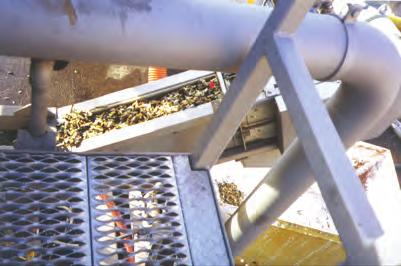


68 23-Modesto4-15Fig A10.AI TYPICAL SLURRYCUP/GRIT SNAIL FIGURE 1.10 HEADWORKS, DRYDEN BOX AND INFLUENT FLUME IMPROVEMENTS


69 23-Modesto4-15Fig A10.AI TYPICAL GRIT CYCLONE/CLASSIFIER FIGURE 1.11 HEADWORKS, DRYDEN BOX AND INFLUENT FLUME IMPROVEMENTS


70 23-Modesto4-15Fig A10.AI COANDA GRIT WASHER ROSF4 FIGURE 1.12 HEADWORKS, DRYDEN BOX AND INFLUENT FLUME IMPROVEMENTS
71 The combined forces of gravity and inertia cause grit and heavier organic particles to settle out of the flow. The separated grit is then washed, which takes place in the bottom portion of the grit washer that generates a fluidized grit bed. After this, the wash water is fed into a bottom chamber to create another fluidized bed, and the vertical flow of water carries the removed low-density organics upward, toward the overflow weir. The heavier grit remains within the fluidized bed. Periodically, washed grit is removed through the bottom of the unit. The grit drops into the inclined screw and is conveyed above the water level in the grit washer where it is drained by gravity. The washed and dewatered grit then drops into a dumpster from the conveyor. The COANDA grit washer is a relatively new proprietary technology. It has been implemented in the United States for approximately 10 years and has been implemented in over 40 US WWTPs. The equipment cost of a COANDA grit washer system is likely greater than a cyclone/classifier system. However, based on our experience with other facilities, the O&M and lifecycle cost is likely about the same or lower because the COANDA grit washer produces significantly drier, cleaner, and less odorous grit, which results in a lower hauling cost and less foul air to treat Fatal Flaw Screening In Carollo s experience, the Slurrycup /Snail system can be very maintenance-intensive and prone to frequent plugging. For this reason, this system is not recommended and will not be further evaluated Alternative Analysis Table 1.12 summarizes the key pros and cons associated with the cyclone/grit classifier and the COANDA grit washer. Table 1.12 Grit Washing Technology Evaluation Headworks, Dryden Box, and Influent Flume Improvements City of Modesto Alternative Pros Cons Cyclone/Grit Classifier COANDA Grit Washer Highly successful in similar applications. Wide range of hydraulic capacity for medium and large plants. Produces adequate product. Has a moderate capital cost. Produces cleaner, drier, less odorous product. Reduces hauling cost. Provides limited washing of grit. High capital cost. Sole-source required. July DRAFT 1-29 pw://carollo/documents/client/ca/modesto/9777a10/deliverables/tm01/tm01.docx
72 The above headworks screening improvement alternatives were further evaluated based on the criteria summarized in Table Table 1.13 Reliability Evaluation Summary of Grit Washing/Dewatering Alternatives Headworks, Dryden Box, and Influent Flume Improvements City of Modesto Evaluation Criteria Cyclone/Classifier COANDA Grit Washer Capture of fines + 0 Ease of O&M Cleaner Product - + Less Odor - + Hauling Cost - + Power Usage 0 0 Flexibility 0 0 Site Efficiency 0 0 Number of Manufacturers + - Cost 0 0 Ratings: + = Positive comparative characteristic. - = Negative comparative characteristic. 0 = Neutral comparative characteristic. Carollo and City staff visited a plant with an operating COANDA. Based on this site visit, the above information, and first-hand experience with the product, the City selected the COANDA grit washer over the cyclone/grit classifier because it produces a less odorous product that is drier and cleaner. As stated above, based on previous experience, the lifecycle cost (i.e., net present value) of a COANDA grit washer system is anticipated to be about the same or lower than that of a cyclone/classifier system. This is largely due to savings associated with odor control and grit hauling costs. 5.3 Basis of Design Table 1.14 summarizes the design criteria for the selected COANDA. July DRAFT 1-30 pw://carollo/documents/client/ca/modesto/9777a10/deliverables/tm01/tm01.docx
73 Table 1.14 Type Design Criteria - Grit Washer Headworks, Dryden Box, and Influent Flume Improvements City of Modesto Description Units Value (1) Inverted Cone-Shaped Vortex Chamber with Stirrer and Screw Conveyor Technology Huber COANDA RoSF4 Size 3 Number - 2 duty Solids Loading Capacity, each t/hr 2 Hydraulic Capacity, each gpm 400 Power, each hp 2 Estimated Construction Cost $ 0.8 M Notes: (1) All calculated values are based on future flows from the 2007 master plan unless otherwise noted. 6.0 FACILITY LAYOUT The new screening and grit removal equipment in the headworks facility would replace the existing equipment. However, we do not expect any significant changes to the existing layout. Figure 1.13 shows the layout of the new bar screens, and Figure 1.14 shows the layout with the new screenings and grit handling equipment. 7.0 HEADWORKS ANCILLARY SYSTEMS 7.1 HVAC Modifications Background There is a single Air-Handling Unit, AHU-1, for the existing bar screen room and grit and screening handling room. This unit is located outdoors and supplies fresh ventilation and air to the rooms through a metal ductwork system. The metal ductwork shows significant corrosion and will need to be replaced with a higher corrosion-resistant ductwork material. Furthermore, the existing AHU-1 has also been corroding and will need to be replaced with a unit designed to withstand higher H 2 S levels. The current AHU-1 capacity is 16,500 CFM, which is sufficient for a 12 AC/hr ventilation rate and meets the NFPA 820 recommended air rate for area classification. However, historically, the 12 AC/hr ventilation rate for headworks applications do not sufficiently provide a good working environment, and odors remain a nuisance in these buildings HVAC Improvements To improve air quality in the existing bar screen room and grit and screening handling room, the ventilation air rate should be increased from 12 AC/hr to 20 AC/hr. The 20 AC/hr has July DRAFT 1-31 pw://carollo/documents/client/ca/modesto/9777a10/deliverables/tm01/tm01.docx

 BAR SCREEN")


74 23-Modesto4-15Fig A10.AI New Bar Screens (Typ 5) BAR SCREEN OPERATING FLOOR LAYOUT FIGURE 1.13 HEADWORKS, DRYDEN BOX AND INFLUENT FLUME IMPROVEMENTS
 New Screenings")

75 23-Modesto4-15Fig A10.AI New Grit Washers (Typ 2) New Screenings Washer Compactor GRIT AND SCREENING ROOM LAYOUT FIGURE 1.14 HEADWORKS, DRYDEN BOX AND INFLUENT FLUME IMPROVEMENTS
76 been used in these types of applications and has shown to improve odor capture and air quality while providing a better and safer working environment for plant staff. Table 1.15 shows the current and proposed airflow capacity, as well as the number of airhandling units in use. This table shows that an increase of 11,000 CFM will need to be exhausted and treated in the biofilter odor control system. Table 1.15 Design Criteria HVAC Improvements Headworks, Dryden Box, and Influent Flume Improvements City of Modesto Air Rate Number of AHUs Bar Screen room Grit Screening & Handling room Total Current 12 ac/hr 1 10,350 cfm 6,150 cfm 16,500 cfm Proposed 20 ac/hr 2 17,250 cfm 10,250 cfm 27,500 cfm We recommend installing two air-handling units, each with a capacity of 13,750 CFM. Two units will provide a more reliable configuration than one. Additionally, the existing metal ductwork will be replaced with fiberglass-reinforced plastics ductwork, a proven material that is used extensively in applications of high H 2 S levels. New ductwork will also be installed in the bar screen room and the grit screening and handling room to improve the air supply and air capture in those areas. The proposed air-handling units will be located outdoors, as shown in Figure The units will be specified with double wall metal casing of either stainless steel or heavy gauge galvanized steel with corrosion-resistant powder coating to withstand the high H 2 S levels. The specifications will list reputable manufacturers that have shown sufficient and proven installations in wastewater treatment plants. Table 1.16 shows a comparison of three manufacturers for the proposed air-handling unit. Figure 1.16 shows the different manufacturers configurations for the air handler. Table 1.16 AHU Manufacturer Evaluation Headworks, Dryden Box, and Influent Flume Improvements City of Modesto Criteria TRANE ENGINEERED AIR YORK Casing Exterior Coating Insulation Accessibility Fan Filters Controls Cost Each AHU $30,000 $38,000 $36,000 July DRAFT 1-34 pw://carollo/documents/client/ca/modesto/9777a10/deliverables/tm01/tm01.docx

77 Screenings & Grit Handling Pumping Plant No. 3 Parshall Flume Grit Basins Bar Screens Enclosed Screw Pumps Electrical Building Existing Odor Control Blowers New Wall Connect New Foul Air Duct to Exisitng Buried Duct Existing Biofilter AHU No. 1 AHU No. 2 Existing Biofilter New Wall LEGEND Existing Foul Air Air Supply New Foul Air 23-Modesto4-15Fig A10.AI ODOR CONTROL AND HVAC LAYOUT FIGURE 1.15 HEADWORKS, DRYDEN BOX AND INFLUENT FLUME IMPROVEMENTS


78 23-Modesto4-15Fig A10.AI TRANE ENGINEERED AIR YORK AIR HANDLING UNIT MANUFACTURER CONFIGURATIONS FIGURE 1.16 HEADWORKS, DRYDEN BOX AND INFLUENT FLUME IMPROVEMENTS
79 7.2 Odor Control Modifications The existing biofilter odor control system consists of two cells with a total treatment capacity of 28,600 CFM. As previously discussed in Section 7.1.2, the HVAC improvements to the bar screen room and the grit screening and handling room will result in an additional 11,000 CFM to be treated. The following is the criteria associated with the biofilter modifications. Table 1.17 shows the design criteria for the existing and expanded biofilter. Table 1.17 Biofilter Odor Control System Capacity Headworks, Dryden Box, and Influent Flume Improvements City of Modesto Description Current Air Flow (CFM) Proposed Air Flow (CFM) Bar Screen Room 8,150 14,700 Bar Screen Channels 5,400 5,400 Grit and Screening Handling Room 6,750 11,200 Influent Pump Station 2,900 2,900 Grit Removal Basins 2,400 2,400 Pumping Plant 3 3,000 3, Empty Bed Residence Time Total 28,600 39,600 Empty Bed Residence Time (EBRT) is the time it takes for air to flow through a volume the same size as the media bed. Since contact time is difficult to estimate, EBRT is typically used to create sizing criteria for biological scrubbers. A high EBRT indicates that the airflow is in contact with the media for a longer time, meaning removal efficiencies are also higher. Additionally, a higher EBRT results in a lower airflow-loading rate and a lower pressure drop, which lowers energy consumption. An EBRT range between 40 to 60 seconds is typically recommended for Biofilters. This range: Is based on successful historical performance. Accounts for greater H 2 S and total odor removal efficiency. Accounts for variables such as operation, interruptions, and changes in environment. Allows for more irregular loading conditions such as spikes in H 2 S concentration levels. Yields faster recovery of the biological population. July DRAFT 1-37 pw://carollo/documents/client/ca/modesto/9777a10/deliverables/tm01/tm01.docx
80 7.2.2 Biofilter Size and Location The existing biofilter treats 28,600 CFM of foul air and consists of two cells. Each cell is approximately 48 feet wide by 80 feet long and has 4 feet of soil media bed. However, only 60 feet of the 80-foot length is used for air treatment. This is because each cell has a 16-foot access ramp for maintenance and removal of the media and other components in the biofilter. In order to treat the additional 11,000 cfm of foul air described in Section 7.2, the access ramp will need to be modified. To do this, the access ramp will be demolished, and a new concrete slab and walls will be constructed to match the biofilter s existing slab. With these modifications, each cell will be expanded to treat 19,800 CFM instead of the current 14,300 CFM. Additionally, the media bed will be expanded to 4.5 feet to provide an EBRT of 52 seconds, which is sufficient for the removal of odorous compounds. Since there are two cells, all of the foul air can be treated temporarily at a reduced rate in one cell when the other cell is out of service for maintenance. Figure 1.15 shows the size of the new biofilter and the proposed modifications Odor Removal and Efficiency The biofilter will be designed primarily to remove H 2 S. However, it will also remove some reduced sulfur compounds and VOCs depending on the media selected and the residence time. Typical historical values for H 2 S emissions from the headworks range from 10 ppm to 50 ppm. Therefore, we recommend a design for a daily average H 2 S of 10 to 50 ppm and a removal efficiency of 95 to 99 percent, which is the typical historical removal efficiency for biofilters Structural Considerations The expanded biofilter will have new walls and slabs constructed of concrete similar to the existing ones. It will also be designed to meet the seismic Zone 4 requirements and local and state codes. Furthermore, the new biofilter walls will be lined with a T-lock liner material to prevent corrosion and withstand the acidity of the drainage water, which can have a ph as low as 2. To prevent corrosion, we also recommend lining the existing Biofilter walls and slab with an arrow-lock liner, which is similar to the T-lock liner material but is typically used for existing installations Biofilter Media The existing media is a soil organic media, which is a mixture of compost, wood chips, and mulch. This type of media decomposes with time and typically last about three to six years depending on the odor concentration and how efficiently and properly the biofilter is maintained. When the media decomposes, it causes air channeling through the media and July DRAFT 1-38 pw://carollo/documents/client/ca/modesto/9777a10/deliverables/tm01/tm01.docx
81 inefficient air distribution. This increases system pressure and increases energy consumption. Criteria for Biofilter media selection is based on the following: Non-proprietary media. Successful historical data. Suitability for a large and diverse microbial population. ph buffering capabilities. Microbe retainability. Physical stability and high porosity to limit the pressure drop for the airflow. Several material options exist for the biofilter s media bed, including proprietary and nonproprietary media. Non-proprietary media include inorganic mineral-based media, such as lava rock and shale, and organic media, such as mixtures of soil and aged bark products. Proprietary media include both engineered synthetic-structured media, such as reticulated foam, and engineered coated inorganic media. Figure 1.17 shows the different types of media used in biofilters. Carollo recommends using non-proprietary inorganic media lava rock for the biofilter. This is because the lava rock media has advantages over other media, such as its low-pressure drop, its large surface area for bacteria growth, its efficient air distribution, its sustainable removal efficiencies throughout the life of the lava rock, and its longer life at low ph levels. The typical life expectancy for lava rock is over twenty years. The lava rock should also help to even water distribution, keep the media moist for longer periods, and prevent weed growth Irrigation System Irrigation is necessary to keep the media moist. This is one of the most important parts of maintaining healthy organisms in the media. The irrigation system will consist of humidification atomizers in the biofilter s inlet air plenum and the sprinklers that irrigate the top of the media bed. The existing irrigation system will be modified to include solenoid control valves monitored by adjustable timers. Furthermore, the system s irrigation piping will consist of chlorinated polyvinyl chloride (CPVC) Schedule 80 Plastic pipes Air Distribution System The existing biofilter uses a type of grating plenum system for air distribution. This system is inefficient and causes air channeling and short-circuiting, even in an area with a large footprint. Typically, biofilters use perforated laterals or slotted base plates, both of which have excellent performance records. For this reason, Carollo recommends replacing the July DRAFT 1-39 pw://carollo/documents/client/ca/modesto/9777a10/deliverables/tm01/tm01.docx


82 23-Modesto4-15Fig A10.AI BIOFILTER MEDIA TYPES FIGURE 1.17 HEADWORKS, DRYDEN BOX AND INFLUENT FLUME IMPROVEMENTS
83 existing grating distribution system with the slotted base plate system. This system has the following advantages over the perforated lateral system and the grating system: Better air distribution across the media. Lower pressure drop. Distribution slots are less prone to plugging. Sturdy and not susceptible to breakage. Ease of maintenance and removal of media. It should be noted that the slotted base plate distribution system is more costly than the perforated lateral system by approximately 30 to 40 percent. For a comparison of these types of air distribution systems, consult Figure Foul Air Ductwork The process facilities foul air conveying duct system will consist of fiberglass reinforced plastic (FRP) material. FRP is not corroded by foul air and is typically used in foul air applications. New FRP ductwork will be installed in the barscreen room and the grit and screening handling room to convey exhausted foul air to the existing buried ductwork and the biofilter. Figure 1.15 shows the new exhaust ductwork for these rooms Drainage The biofilter expansion will require draining the collected irrigation water. However, the facility will retain the existing drainage system Fans Currently, three FRP centrifugal fans send foul air from the headworks facilities to the existing biofilter. Each fan has a 75 hp constant speed motor and a capacity of 14,300 CFM at a 17-Inch WC. Normally, only two fans are in operation, and the third fan acts as a standby. To accommodate increases in foul air, we recommend putting all three existing fans in operation. If a fan is out of service, the two remaining fans will send the foul air to the biofilter at a temporarily reduced rate until the out-of-service fan is back in operation. Replacing the media will lower the system s pressure drop. Therefore, the existing fans will need to be throttled to maintain the correct airflow rate. Throttling will apply backpressure to the fans and make them draw more horsepower than is needed. To avoid this, Carollo recommends retrofitting the existing 75 hp fans motors with VFDs so the fan speed can be adjusted to account for pressure variations within the system and to maintain the exhaust foul airflow rate. This will also conserve energy and will help balance the foul air system. July DRAFT 1-41 pw://carollo/documents/client/ca/modesto/9777a10/deliverables/tm01/tm01.docx


84 23-Modesto4-15Fig A10.AI Header laterals air distribution piping system. BIOFILTER AIR DISTRIBUTION SYSTEMS Baseplate Air Plenum Distribution System. FIGURE 1.18 HEADWORKS, DRYDEN BOX AND INFLUENT FLUME IMPROVEMENTS
85 Permitting The plant s air is permitted by the Bay Area Air Quality Management District (BAAQMD). Since the existing biofilter will be modified and expanded to treat more foul air than the current treatment, the City will need to obtain one permit from BAAQMD to construct the new odor control system and another permit to operate it. Typically, this requires two phase submittals. The first phase is to submit the air permit application along with the necessary technical data, including preliminary drawings and specifications, to the BAAQMD for review. This must happen during the design phase and before construction begins. Afterward, the BAAQMD will review the material and grant the City a permit. The second phase occurs after the odor control system has been constructed and is operating for a period specified in the permit to construct requirements. Then, the BAAQMD will conduct field source testing for odorous compounds to confirm that operation and removal efficiencies comply with both the design and the permit to construct requirements. At that point, results of the field odor testing will be submitted to the BAAQMD for review. After successful review, the BAAQMD will grant the City a permit to operate the biofilter facility Summary Design Criteria Table 1.18 Design Criteria Odor Control Modifications Headworks, Dryden Box, and Influent Flume Improvements City of Modesto Equipment Units Existing Biofilter Expanded Biofilter Biofilter Capacity cfm 28,600 39,600 Footprint Size - 48' W x 130' L 48' W x 160' L Number of Cells 2 cells (each 48' w x 65' L) 2 cells (each 48' w x 80' L) Media - Soil media Lava Rock (1) Media Depth feet (2) EBRT seconds Differential Pressure inch WC 4-8 in. 4-6 in. Air Distribution System Type - grating plenum slotted base plates (3) Number of Operating Fans (4) Estimated Construction Cost $2.4 M Notes: (1) Existing soil media will be replaced with lava rock media. (2) Existing 4-foot media will be replaced with a new bed depth of 4.5 feet. (3) Existing header perforated lateral system will be replaced with a slotted base plate air distribution system. (4) Replacing the existing constant speed fans' motors with VFDs is recommended. July DRAFT 1-43 pw://carollo/documents/client/ca/modesto/9777a10/deliverables/tm01/tm01.docx
86 8.0 ELECTRICAL REQUIREMENTS The electrical systems for this project will be designed for general compliance with the standards set by the National Electrical Manufacturers Association (NEMA), American National Standards Institution (ANSI), Institute of Electrical and Electronics Engineers (IEEE), and Underwriters Laboratory, Inc. (UL). The following codes and standards are provided as design references: NFPA 70: National Electric Code. NFPA 101: Life Safety Code. NFPA 110: Emergency and Standby Power Systems. NFPA 820: Fire Protection in Wastewater Treatment and Collection Facilities. The existing Motor Control Center P18 (MCC- P18 ) is a power distribution system for the Headworks Pumping Plant. The existing MCC- P18 is rated 1,600 A main bus with a 1,600 A main breaker. Based on a preliminary load analysis of the existing MCC- P18, the MCC is currently operating at 1,362.3 A. Refer to Appendix A for the operation condition of the existing MCC- P18. The existing MCC- P18 will need to be modified to eliminate existing loads and better accommodate new loads. Based on the proposed modifications to the existing MCC- P18, the MCC will operate at 1,433.5 A. According to a preliminary load analysis, the existing MCC- P18 has the capacity to accommodate additional loads. However, a detailed load analysis would be required to determine the existing MCC s spare capacity. To accomplish this, 1 month of data would be collected in accordance with the NEC guidelines. Refer to Appendix B for a modified load analysis of the operation condition of the existing MCC- P18. Refer to Figure 1.19 for information on the demolition of the existing MCC- P18, and Figure 1.20 for modifications to the existing MCC- P CONTROL PHILOSOPHY OVERVIEW This section explains general control concepts for the proposed headworks improvements. Major process equipment would have both local and remote control capabilities. Manual controls would be added at the equipment, and remote controls would be available at a SCADA system. Most of the major process equipment would also have automatic controls. 9.1 Screening System Overview The screening system would include the following new and existing automatically controlled equipment: Existing bar screens inlet and outlet channels. July DRAFT 1-44 pw://carollo/documents/client/ca/modesto/9777a10/deliverables/tm01/tm01.docx
87 MCC-P18, 1600A, 3PH, 3 WIRE RVSS RVSS RVSS RVSS ATS-16 12KW Y2 Y2 3/ KW HC-2 AHU-2 PRV-1 PRV-2 VSP-1A Sump Pump VSP-1B Sump Pump GC-1 Grit Chamber GC-2 Grit Chamber GC-3 Grit Chamber GW-1 Grit Chamber GW-2 Grit Chamber CN-1 Screenings Conveyor CP-1 Screenings Compactor HC-1 AHU-1 IP-1 Influent Pump IP-2 Influent Pump IP-3 Influent Pump IP-4 Influent Pump SUP-1 Holding Basin Pump SUP-2 Holding Basin Pump MCC-P18, 1600A, 3PH, 3 WIRE J Modesto4-15Fig A10.AI SLG-6 SLG-7 SLG-8 SLG-9 SLG-10 SG-1 Bar Screen SG-2 Bar Screen SG-3 Bar Screen SG-4 Bar Screen 18L BLW-1 Blower BLW-2 Blower BLW-3 Blower GP-1 Grit Pump GP-2 Grit Pump GP-3 Grit Pump GP-5 Grit Pump GP-6 Grit Pump MCC-P18 DEMO ONE-LINE DIAGRAM FIGURE 1.19 HEADWORKS, DRYDEN BOX AND INFLUENT FLUME IMPROVEMENTS
88 MCC-P18, 1600A, 3PH, 3 WIRE RVSS RVSS RVSS RVSS ATS-16 12KW / KW VSP-1B GC-1 GC-2 GC-3 GC-4 Grit Grit CN-1 HC-1 AHU IP-1 IP-2 IP-3 IP-4 Sump Grit Grit Grit Grit Washer Washer Screenings No.1 Influent Influent Influent Influent Pump Chamber Chamber Chamber Chamber No. 1 No. 2 Conveyor Pump Pump Pump Pump HC-2 AHU-2 PRV-1 PRV-2 VSP-1A Sump Pump Screenings Washer Compactor Motor Screenings Washer Compactor Auger SUP-1 Holding Basin Pump SUP-2 Holding Basin Pump MCC-P18, 1600A, 3PH, 3 WIRE J Modesto4-15Fig A10.AI SLG-6 SLG-7 SLG-8 SLG-9 SLG-10 BAR SCREEN NO.1 BAR SCREEN NO.2 BAR SCREEN NO.3 BAR SCREEN NO.4 BYPASS CHANNEL BAR SCREEN 18L BLW-1 Blower BLW-2 Blower BLW-3 Blower GP-1 GP-2 GP-3 GP-5 GP-6 GRIT PUMP AHU NO.3 SLG-11 SLG-12 SLG-13 SLG-14 SLG-15 MCC-P18 MODIFICATION ONE-LINE DIAGRAM FIGURE 1.20 HEADWORKS, DRYDEN BOX AND INFLUENT FLUME IMPROVEMENTS
89 New bar screens. Existing bypass channel inlet and outlet gates. A new channel level monitoring system. Local and remote controls would be provided unless otherwise noted. Normal operation would be in remote automatic mode. The bar screen channels would be automatically placed in service based on the influent flow or liquid level in the screening channels. The bar screens would operate periodically to remove debris from the flow stream when material accumulates on the bar rack. They would deposit the screenings into the existing conveyor. Level sensors mounted in the bar screen inlet and outlet channels would monitor liquid levels upstream and downstream of the bar screens Existing Bar Screen Channel Gates Each existing bar screen channel has an inlet gate and outlet gate for isolation. The inlet gates are equipped with a motorized operator with provisions for local and remote control. The channel outlet gates would also be motorized for automated control. Furthermore, the inlet and outlet gates would open when the associated bar screen channel is in service and close when the channel is out of service. The gates would open automatically to put additional bar screen channels in service based on influent flow rate, high differential level measured across the bar screens, or high level measured upstream of the screens. The gates would close automatically when a bar screen fails Bar Screens When a bar screen channel is in service (i.e., inlet and outlet gates are open) the associated bar screen operation would be initiated automatically. A bar screen rake cycle would be initiated based on differential level across the bar screens, high level upstream of the screens, or a pre-programmed time lapse. When a rake cycle is initiated, the bar screen would operate for an adjustable time period and then stop. When multiple bar screen channels are in service, the bar screens would operate sequentially, with an adjustable time delay between each screen Bypass Channel Gates The bypass channel has existing inlet and outlet gates for isolation. In this channel, a new bypass screen with larger bar spacing would be installed. The existing bypass channel inlet gate is equipped with a motorized operator with provisions for local and remote control. The bypass channel outlet gates would also be motorized for automated control. Normally, both July DRAFT 1-47 pw://carollo/documents/client/ca/modesto/9777a10/deliverables/tm01/tm01.docx
90 gates would be closed. The gates would open only if the influent flow cannot be accommodated with all available bar screen channels in service. The excess flow would then be screened through the bypass screen with larger bar spacing Bypass Screen Gates The new bypass screen in the bypass channel would have side bypass gates for excess flow in case all screens in service (including the bypass screen) could not accommodate the influent flow. The bypass gates attached to the bypass screen would be opened manually (i.e., initiated by an operator locally or remotely) to create unscreened flow bypass. In the event of a high differential liquid level across the bar screen channels, an alarm would be annunciated and operations would choose whether to open the bypass gates or open one gate. The gates would remain open until manually closed Channel Level Monitoring The channel level monitoring system would be added to the existing channels to measure liquid levels in the bar screen inlet and outlet channels and to transmit the level data to the SCADA system for remote monitoring and control of the screening system. 9.2 Screenings Handling System Overview The screenings handling system includes an existing screenings conveyor and a new washer/compactor. Local and remote controls would be also provided to the new equipment unless otherwise noted. The equipment s normal operation would be in remote automatic mode. Under normal operation, the existing screenings conveyor would collect raw screenings removed by the bar screens and transport the material to the new washer/compactor. The washer/compactor would wash and dewater the screenings and discharge them into the existing tipping trough Existing Screenings Conveyor The existing screenings conveyor would collect raw screenings discharged from the new bar screens and convey the material to the new screenings washer/compactor. The screenings conveyor would start after a bar screen starts and continue to run for a predetermined time period after the bar screen stops. If the screenings conveyor is out of service for an extended period of time, the conveyor would be bypassed temporarily by discharging raw screenings directly from the bar screens into a tipping bin or other temporary receptacle. July DRAFT 1-48 pw://carollo/documents/client/ca/modesto/9777a10/deliverables/tm01/tm01.docx
91 9.3 Screenings Washer/Compactor The new screenings washer/compactor would accept raw screenings discharged from the existing screenings conveyor. The washer/compactor would wash the screenings to remove organic material and to dewater the washed screening before it discharges into the existing tipping trough for disposal. The contributing conveyor would start first, followed by the screenings washer/compactor, which would continue to run for a predetermined time period after the conveyor stops. The screenings washer/compactors would normally operate in a batch mode that first washes the screenings at multiple locations within the unit using the auger s cycling action combined with spray water. When the wash cycle ends, the unit dewaters the screenings by pushing them through a constricted press zone, and then discharges the material into the screenings bin. The washer/compactors can also be operated in a continuous discharge mode, which increases the throughput capacity but reduces washing effectiveness. 9.4 Grit Handling System Overview The grit-handling system includes the following equipment: Grit pump suction valves. Grit pumps. A pump seal water system. Grit slurry flowmeters. Grit washers. The grit-handling system would be provided with local and remote controls unless otherwise noted. Under normal operation, the system would be in remote automatic mode. When a grit basin is in service, its duty grit pump would run continuously and discharge to the grit washer in its train. During this continuous feed mode, the washwater feed and the stirrer at the grit washer would cycle on and off according to timers. In addition, the grit screw at the grit washer would operate based on the grit level measured by a pressure switch; when the grit level rises and remains above the grit level start set point, the screw would start. The screw would stop when the grit level falls and remains below the grit level stop set point. The organic valve at the grit washer would cycle between the open and closed positions according to a timer. When the feed pumping halts, the grit washer system would undergo an automatic shutdown cycle. July DRAFT 1-49 pw://carollo/documents/client/ca/modesto/9777a10/deliverables/tm01/tm01.docx
92 9.5 Odor Control Under normal operation, all three existing biofilter fans will operate continuously. Adequate instrumentation monitoring and controls would be provided so the biofilter facility can operate as a self-contained system. At a minimum, this would include monitoring the fan s status and installing pressure gauges across the media bed to monitor pressure drops and the fan s suction and discharge. The final design stage would determine the level of coordination and integration required for the existing control system CONSTRUCTION SEQUENCING 10.1 Headworks Screening Construction sequencing for the bar screen replacement at the headworks facility would mainly depend on the number of channels that must be in service during construction. Capacity estimates of the existing screening channels indicate that two existing screens online at a time should provide sufficient screening capacity for the current peak day flows. A potential construction sequence was developed for the modifications. First, the existing isolation gates would isolate three of the screening channels, including the bypass channel. If necessary, sand bags would be used as a backup upstream of the influent gates. Once the two existing screens are replaced and the bypass screen is installed in the bypass channel, the new screens would be brought online and operated. The remaining two screening channels would then be similarly isolated and the screens replaced. Bypass pumping is not desirable, and all screening modifications could be made without bypass pumping except when emptying the isolated channels is required Grit Basin Modifications Construction of the grit basin modification would be sequenced to continue grit removal during construction. Grit removal and grit pumping and handling would be kept online during modifications to the grit basins. One grit basin and its associated grit pump would be taken out of service at a time. The existing grit classifiers would be kept online. The existing grit basin isolation gates would be used to isolate each basin for modifications. Having one or two grit basins online at a time would sufficiently handle the current peak day flows. Each grit basin and grit pump would be put back online when the modifications are finished Screenings and Grit Handling The existing screenings conveyor and washer compactor would be kept online during bar screen replacement. Temporary receptacles would be used to collect screenings during the new washer compactor s installation. Each of the two existing grit classifiers is connected to two of the four grit basins. The grit basins associated with each grit classifier would be taken offline while the classifier is July DRAFT 1-50 pw://carollo/documents/client/ca/modesto/9777a10/deliverables/tm01/tm01.docx
93 removed and replaced with the new washer. Once the grit washer has been replaced, it would be brought online, and the second train of grit basins, grit pumps, and washer classifier would be taken offline to replace the washer classifier SUMMARY OF PROPOSED IMPROVEMENTS The key findings and recommendations for the headworks improvement process are as follows. The improved headworks facilities should be designed to accommodate the 2035 peak hourly flow of 95.5 mgd. Equipment would be sized to handle the flow range between the minimum diurnal flow and the 2035 peak wet weather flow. Screening: Replace all existing climber screens with chain-driven multi-rake type screens. New screens will have a clear opening of 1/4 inch. Install a 4-foot wide 1/2-inch bypass screen in the bypass channel. Provide 1-foot wide bypass gates on either side of the bypass screen to bypass peak flows. Motorize any manual screening channel inlet or outlet gates. Add channel level monitoring to the screening channels. Screenings Handling: Install a new skid mounted muffin monster washer compactor. Mount the existing washer compactor on a skid and store for redundancy. Grit Removal: Install a grit-removal mechanism in the existing Grit Basin No. 4 and bring the unit online. Install a deflector baffle on the grit basins inlet to divert the influent flow to the outer perimeter of the basin wall. Add a lip to the grit chamber effluent to raise the elevation and to decrease the settling depth required for the fine particles to be captured in the basin. Reduce the impeller speed in all four grit basins to reduce the loss of fine grit and to increase capture. A grit pump would need to be installed for the fourth basin when it is brought online. However, this would be done as part of another project. Grit Handling: Replace the existing cyclone/grit classifiers by installing two COANDA grit washers for grit washing/dewatering. July DRAFT 1-51 pw://carollo/documents/client/ca/modesto/9777a10/deliverables/tm01/tm01.docx
94 HVAC Modifications: Increase the ventilation foul air rate from 12 AC/hr to 20 AC/hr to the bar screen room and building and to the grit and screening handling room. Replace the existing metal air ductwork in the headworks building with FRP ductwork. Replace the existing AHU with two new AHUs. Odor control modifications: Design the biofilter s inlet H2S with a daily average of 15 ppm and spikes of 25 ppm. This would have a removal efficiency of 95 to 99 percent. Use lava rock media for the biofilter. Use a slotted base plate plenum air distribution system for the biofilter. Use VFDs for the existing biofilter fans. Install an arrow-lock liner for the concrete slabs and walls of the existing biofilter. Use FRP ductwork for the new exhaust foul air system and biofilter. The following provisions are also recommended to adequately contain and exhaust odors generated at the influent pump station: Replace covers to the existing screw lift pumps. Keep the roll-up doors closed to the existing grit and screening handling room CONSTRUCTION COST ESTIMATES Construction cost estimates were based on preliminary design criteria and several assumptions. Final project costs will depend on several factors, including actual labor and material costs, the time period in which the facilities are constructed, productivity, competitive market conditions, final project scope, project schedule, environmental conditions, and other variable factors. Consequently, final project costs will vary from the cost estimates presented in this TM. Because of these factors, funding needs must be carefully reviewed before making specific financial decisions or establishing final budgets. The estimates for the scenarios are in March 2015 dollars (ENR Los Angeles Construction Cost Index = 10995). The level of accuracy for estimating construction costs varies based on the level determined for the project. Feasibility studies and master plans represent the lowest level of accuracy, while pre-bid estimates (based on detailed plans and specifications) represent the highest level. The American Association of Cost Engineers (AACE) has developed the following guidelines: Type of Estimate Anticipated Accuracy Order-of-Magnitude (Master Plans) +50% to -30% Budget Estimate (Predesign Report) +30% to -15% Definitive Estimate (Pre-Bid) +15% to -5% July DRAFT 1-52 pw://carollo/documents/client/ca/modesto/9777a10/deliverables/tm01/tm01.docx
95 The estimates presented in this TM are at the budget estimate accuracy level (Class 4). The cost estimates were developed using a combination of quantity takeoffs, unit prices, and bid prices for past projects. Allowances for contractor overhead and profit, inflation, and sales tax were added to the construction cost estimates for both alternatives Cost Estimate Assumptions The cost estimates presented were prepared before detailed engineering effort was determined and are therefore preliminary. As such, the following contingencies were applied to each of the estimates: General conditions: 9 percent. General contingency for unforeseen conditions, changes, or design details: 20 percent. General contractor overhead, profit, and risk: 10 percent. Escalation to the mid-point of construction: costs have been presented in present-day dollars with no escalation. This is because the construction period for this project is not definite. Sales tax on materials: 8.1 percent on half of the estimated items, assuming that materials, which are taxable, comprise 50 percent of the estimated direct costs Cost Estimates The design criteria tables include cost estimates for each improvement or improvement alternatives. The total estimated project cost will be included in the Draft Preliminary Design Report. July DRAFT 1-53 pw://carollo/documents/client/ca/modesto/9777a10/deliverables/tm01/tm01.docx
96 Technical Memorandum No. 1 APPENDIX A LOAD ANALYSIS ON EXISTING "MCC-P18" pw://carollo/documents/client/ca/modesto/9777a10/deliverables/tm01/tm01.docx
97 7/2/2015 3:30 PM Client View NON-MCC ELECTRICAL LOAD LIST - V CLIENT VIEW City of Modesto EQPT: MCC Headworks, Dryden Box, and Influent Flume Improvement VOLTS: A10 PHASE: 3 MCC-18 WIRE: 3 Existing Load Analysis MIN BUS 2000 AMPS Hamid Sukar RATING: 65 KASC MINIMUM FEEDER SIZE: 1637 AMPS LOAD DATA ENG-GEN DESCRIPTION 1 DESCRIPTION 2 DESCRIPTION 3 DESCRIPTION 4 TAG (EQUIPMENT NUMBER): ( MAJOR LOADS ) VALUE: Enter Numerical Value: Breaker Trip, MLO Value, Motor Hp, Packaged Eqpt Load, or XFMR KVA If SUBFED LOAD: Max Amps UNITS Load Type DUTY (See Note 5) C = Continuous, I = Intermittent, S = Standby STARTING METHOD (Motors Only) STANDBY DESIGNATION (See Note 6) CE = Controllable Essential NCE = Non-Controllable Essential CNE = Controllable Non-Essential NCNE = Non-Controllable Non-Essential HC KW I NCNE AHU HP I FVNR NCNE PPV HP C FVNR NCE PPV HP C FVNR NCE FLOAT SWITCH MECHANICAL ALTERNATOR VSP-1A 1.50 HP S FVNR CE FLOAT SWITCH MECHANICAL ALTERNATOR VSP-1B 1.50 HP C FVNR CE GRIT CHAMBER NO. 1 GC HP C FVNR CE GRIT CHAMBER NO. 2 GC HP C FVNR CE GRIT CHAMBER NO. 3 GC HP C FVNR CE GRIT CHAMBER NO. 4 GC HP C FVNR CE GRIT WASH GW HP C FVNR CE GRIT WASH GW HP C FVNR CE SCREENINGS CONVEYOR CN HP C FVNR CE SCREENINGS COMPACTORS CP HP C FVNR CE HC KW I FVNR NCNE AHU HP I FVNR NCNE DF HP I FVNR NCNE INFLUENT PUMP IP HP S RVSS CE INFLUENT PUMP IP HP C RVSS CE INFLUENT PUMP IP HP C RVSS CE HOLDING BASIN PUMPS SUP HP C RVSS CE HOLDING BASIN PUMPS SUP HP C RVSS CE INFLUENT PUMP IP HP C RVSS CE SL -GATES 6 THRU CB.or.FUSE I PANELBOARD 18L KVA I NCNE SL -GATES 11 THRU CB.or.FUSE I CE BAR SCREEN CONTROL PANEL SC HP C FVNR CE BAR SCREEN CONTROL PANEL SC HP C FVNR CE BAR SCREEN CONTROL PANEL SC HP C FVNR CE BAR SCREEN CONTROL PANEL SC HP C FVNR CE BLOWER BLW HP C FVNR NCE BLOWER BLW HP C FVNR NCE BLOWER BLW HP S FVNR NCE GRIT PUMP GP HP C FVNR CE GRIT PUMP GP HP C FVNR CE GRIT PUMP GP HP C FVNR CE GRIT PUMP GP HP C FVNR CE GRIT PUMP GP HP S FVNR CE LOAD TOTALS POWER AMP SUMMARY CONTROLLABLE ESSENTIAL (C/E) 757 KVA 911 AMPS NON-CONTROLLABLE ESSENTIAL (NC/E) - Note KVA 203 AMPS CONTROLLABLE NON-ESSENTIAL (C/NE) NON-CONTROLLABLE NON-ESSENTIAL (NC/NE) 207 KVA 249 AMPS OPERATING LOAD TOTAL - Note 1 >> KVA AMPS EQUIPMENT SIZING CAROLLO - Note 2 >> KVA AMPS EQUIPMENT SIZING NEC - Note 3 >> KVA AMPS STDBY BUS OPERATING TOT. - Note 4 >> KVA AMPS STANDBY BUS SIZING CAROLLO >> KVA AMPS
98 Technical Memorandum No. 1 APPENDIX B LOAD ANALYSIS ON MODIFIED EXISTING "MCC-P18" pw://carollo/documents/client/ca/modesto/9777a10/deliverables/tm01/tm01.docx
99 7/2/2015 3:35 PM Client View NON-MCC ELECTRICAL LOAD LIST - V CLIENT VIEW City of Modesto EQPT: MCC Headworks, Dryden Box, and Influent Flume Improvement VOLTS: A10 PHASE: 3 MCC-18 Modify WIRE: 3 Modified Load Analysis MIN BUS 2000 AMPS Hamid Sukar RATING: 65 KASC MINIMUM FEEDER SIZE: 1729 AMPS LOAD DATA ENG-GEN DESCRIPTION 1 DESCRIPTION 2 DESCRIPTION 3 DESCRIPTION 4 TAG (EQUIPMENT NUMBER): ( MAJOR LOADS ) VALUE: Enter Numerical Value: Breaker Trip, MLO Value, Motor Hp, Packaged Eqpt Load, or XFMR KVA If SUBFED LOAD: Max Amps UNITS Load Type DUTY (See Note 5) C = Continuous, I = Intermittent, S = Standby STARTING METHOD (Motors Only) STANDBY DESIGNATION (See Note 6) CE = Controllable Essential NCE = Non-Controllable Essential CNE = Controllable Non-Essential NCNE = Non-Controllable Non-Essential HC KW I NCNE AHU HP I FVNR NCNE PPV HP C FVNR NCE PPV HP C FVNR NCE FLOAT SWITCH MECHANICAL ALTERNATOR VSP-1A 1.50 HP S FVNR CE FLOAT SWITCH MECHANICAL ALTERNATOR VSP-1B 1.50 HP C FVNR CE GRIT CHAMBER NO. 1 GC HP C FVNR CE GRIT CHAMBER NO. 2 GC HP C FVNR CE GRIT CHAMBER NO. 3 GC HP C FVNR CE GRIT CHAMBER NO. 4 GC HP C FVNR CE GRIT WASHER NO HP C FVNR CE GRIT WASHER NO HP C FVNR CE SCREENINGS CONVEYOR CN HP C FVNR CE HC KW I FVNR NCNE DF HP AHU NO HP C FVNR NCNE AHU NO HP C FVNR NCNE INFLUENT PUMP IP HP S RVSS CE INFLUENT PUMP IP HP C RVSS CE INFLUENT PUMP IP HP C RVSS CE HOLDING BASIN PUMPS SUP HP C RVSS CE HOLDING BASIN PUMPS SUP HP C RVSS CE INFLUENT PUMP IP HP C RVSS CE SL -GATES 6 THRU CB.or.FUSE I PANELBOARD 18L KVA I NCNE SL -GATES 11 THRU CB.or.FUSE I CE BYPASS CHANNEL BAR SCREEN 5.00 HP C FVNR CE BAR SCREEN NO HP C FVNR CE BAR SCREEN NO HP C FVNR CE BAR SCREEN NO HP C FVNR CE BAR SCREEN NO HP C FVNR CE BLOWER BLW HP C FVNR NCE BLOWER BLW HP C FVNR NCE BLOWER BLW HP S FVNR NCE GRIT PUMP GP HP C FVNR CE GRIT PUMP GP HP C FVNR CE GRIT PUMP GP HP C FVNR CE GRIT PUMP GP HP C FVNR CE GRIT PUMP GP HP S FVNR CE SCREENINGS WASHER COMPACTOR NO. 1 MOTOR HP C FVNR CE SCREENINGS WASHER COMPACTOR NO. 1 AUGER 3.00 HP C FVNR CE BAR SCREEN NO. 1 OUTLET GATE ACTUATOR 1.00 HP C FVNR CE BAR SCREEN NO. 2 OUTLET GATE ACTUATOR 1.00 HP C FVNR CE BAR SCREEN NO. 3 OUTLET GATE ACTUATOR 1.00 HP C FVNR CE BAR SCREEN NO. 4 OUTLET GATE ACTUATOR 1.00 HP C FVNR CE BAR SCREEN NO. 5 OUTLET GATE ACTUATOR 1.00 HP C FVNR CE LOAD TOTALS POWER AMP SUMMARY CONTROLLABLE ESSENTIAL (C/E) 791 KVA 951 AMPS NON-CONTROLLABLE ESSENTIAL (NC/E) - Note KVA 205 AMPS CONTROLLABLE NON-ESSENTIAL (C/NE) NON-CONTROLLABLE NON-ESSENTIAL (NC/NE) 231 KVA 278 AMPS OPERATING LOAD TOTAL - Note 1 >> KVA AMPS EQUIPMENT SIZING CAROLLO - Note 2 >> KVA AMPS EQUIPMENT SIZING NEC - Note 3 >> KVA AMPS STDBY BUS OPERATING TOT. - Note 4 >> KVA AMPS STANDBY BUS SIZING CAROLLO >> KVA AMPS
100 This document is released for the purpose of information exchange review and planning only under the authority of Esther N. Kinyua, July 31, 2015, State of California, No CITY OF MODESTO HEADWORKS, DRYDEN BOX, AND INFLUENT FLUME IMPROVEMENTS TECHNICAL MEMORANDUM NO. 2 PUMPING PLANT NO. 3 IMPROVEMENTS DRAFT July YGNACIO VALLEY ROAD, SUITE 300 WALNUT CREEK, CALIFORNIA P F pw://carollo/documents/client/ca/modesto/9777a10/deliverables/tm02/tm02
101 CITY OF MODESTO HEADWORKS, DRYDEN BOX, AND INFLUENT FLUME IMPROVEMENTS TECHNICAL MEMORANDUM NO. 2 PUMPING PLANT NO. 3 IMPROVEMENTS TABLE OF CONTENTS Page No. 1.0 INTRODUCTION PROJECT OBJECTIVES DESIGN FLOWS PUMP STATION CONFIGURATION ALTERNATIVES Alternative 1 Add Two Small Dry Pit Pumps to the Existing Pump Station Alternative 2 Replace Two Large Pumps with Smaller Pumps Alternative 3 Add Two Small Submersible Pumps to Existing Wetwell Alternative 5 Extending the Existing Wetwell ALTERNATIVES EVALUATION PUMPING PLANT NO. 3 SCREENING Areas for Improvement Hydraulic Analysis Basis of Design FACILITY LAYOUT PUMPING PLANT NO. 3 ANCILLARY SYSTEMS Pump Discharge Valves ELECTRICAL REQUIREMENTS CONTROL PHILOSOPHY OVERVIEW Pumping Plant No. 3 Pumping Pumping Plant No. 3 Screening SUMMARY AND CONCLUSIONS CONSTRUCTION COST ESTIMATES Cost Estimate Assumptions Cost Estimates APPENDIX A - LOAD ANALYSIS ON EXISTING "MCC-P11" APPENDIX B - LOAD ANALYSIS ON MODIFIED EXISTING "MCC-P11" July DRAFT pw://carollo/documents/client/ca/modesto/9777a10/deliverables/tm02/tm02 i
102 LIST OF TABLES Table 2.1 Design Flows for Pumping Plant No Table 2.2 Alternative 1 Design Criteria Add Two Small Dry Pit Pumps to Existing Pump Station Table 2.3 Alternative 2 Design Criteria Replace Two Large Pumps with Smaller Pumps Table 2.4 Alternative 3 Design Criteria Add Two Small Submersible Pumps to Existing Wetwell Table 2.5 Alternative 4 Design Criteria Submersible Pumps in New Wetwell Table 2.6 Alternative Evaluation Table 2.7 Hydraulics Analysis Pumping Plant No. 3 Screening Table 2.8 Design Criteria Existing Screens Replacement Table 2.9 Can Seg Pumps Discharge Valves LIST OF FIGURES Figure 2.1 Existing Process Flow Diagram Figure 2.2 Existing Pumping Plant No. 3 Process Flow Diagram Figure 2.3 Pumping Plant No. 3 Preliminary Pump and System Head Curves Figure 2.4 Typical Chain-Driven Multi-Rake Screen Figure 2.5 Proposed Pumping Plant No. 3 Layout Figure 2.6 Proposed Pumping Plant No. 3 Layout and Sections Figure 2.7 Existing MCC P-11 Demo Figure 2.8 MCC P-11 Proposed Modifications July DRAFT pw://carollo/documents/client/ca/modesto/9777a10/deliverables/tm02/tm02 ii
103 Technical Memorandum No. 2 PUMPING PLANT NO. 3 IMPROVEMENTS 1.0 INTRODUCTION This technical memorandum (TM) presents the design basis for improvements to Pumping Plant No. 3. Pumping Plant No. 3 pumps process water flows from food-processing industries in the Beard Industrial Park to the Jennings Plant ranch land for use as irrigation water. At the plant, food-processing flows, referred to as "Can Seg" flows, are conveyed through a separate conveyance system (Figure 2.1) to keep domestic wastewater flows from contaminating the Can Seg. Pumping Plant No. 3 is the first stage of this separation process. Discharge from Pumping Plant No. 3 flows through the Can Seg outfall pipeline to the Jennings Plant. At the Jennings Plant, the Can Seg flow is pumped to the irrigation pond, which then uses gravity to distribute flow to the fields. The cannery segregation system conveys industrial wastewater from five different foodprocessing industries within the Beard Industrial Park: Stanislaus Foods, Gallo Winery, Seneca Foods, Del Monte, and Frito-Lay. Only Gallo Winery and Frito-Lay discharge flow year-round. Stanislaus Foods and Del Monte discharge seasonally during the canning season, which generally runs from July through October. During the non-canning season, the year-round Can Seg flows are combined with domestic wastewater, and Pumping Plant No. 3 is shut down. During the canning season, Pumping Plant No. 3 is operated to pump Can Seg directly to the Modesto Ranch located at the Jennings Plant. At the beginning of the canning season, it takes time for the canneries to reach full production. Conversely, the end of the season requires a ramping down. Because the pumps at Pumping Plant No. 3 have a limited turndown range, the separation of Can-Seg flow from municipal wastewater cannot occur until flows reach about 8 mgd. As a result, there is a two- to three-week period prior to and just after the segregation period when elevated flows from the cannery segregation line (CSL) enter the Sutter Plant. Industrial process water contains high levels of biochemical oxygen demand (BOD) that overshadow the loadings from domestic wastewater. This means that shoulder period loadings from Can Seg significantly affect domestic wastewater treatment processes. The Can-Seg diversion operations greatly affect the flows and loads received at the Sutter Plant. For this reason, the following three distinct flow periods were considered in developing the design basis for the improvements to Pumping Plant No. 3. July DRAFT 2-1 pw://carollo/documents/client/ca/modesto/9777a10/deliverables/tm02/tm02
104 Sutter Trunk (Domestic) Ferric Chloride Injection Headworks West Trunk (Domestic and Waste from Hauler Dump Station) Influent Pumps Bar Screens Grit Tanks Primary Clarifiers River Trunk (Domestic) Can Seg Line (Cannery) Sutter Plant Junction Box No. 1 Bar Screens Pumping Plant No. 3 (Can-Seg) M Parshall Flumes PC 1 PC 2 Effluent Pump Station (outfall Pump Station) Domestic Outfall Cannery Segregation Line (CSL) Continued below Secondary Effluent storage Domestic Outfall Secondary Treatment Irrigation Storage Ranch Land Non-Canning Season BNR/ Tertiary Treatment To Offsite Recycled Water User Cannery Segregation Canning Season Line (CSL) Cannery Waste Pump Station Can Seg Flow 23-Modesto4-15Fig A10.AI Jennings Plant EXISTING PROCESS FLOW DIAGRAM FIGURE 2.1 HEADWORKS, DRYDEN BOX AND INFLUENT FLUME IMPROVEMENTS
105 Canning Season: The canneries are at full production. During this period, the CSL conveys Can Seg flow through the Dryden Box to Pumping Plant No. 3. During canning season the major non-cannery flows are combined with the cannery flows. The canning period typically begins in July and ends in late September or early October. Based on 2012 data, flows during canning season averaged 15 mgd, and peak hourly flows were as high as 25 mgd. Shoulder Period: During this period, Can-Seg flows are included into the Sutter Plant during the ramp-up and ramp-down periods at the beginning and end of peak canning season. During this time, Can-Seg flows range between approximately 2 and 7 mgd. Pumping Plant No. 3 begins its seasonal operation when this period begins. Non-Canning Season: Currently, Can Seg flows during the non-canning season are combined with domestic flows and treated in domestic treatment facilities. During this period, Can-Seg flows are typically less than 2 mgd. Improvements to Pumping Plant No. 3 at the Sutter Plant will divert Can-Seg flows around the Sutter Plant year-round. Similarly, Pumping Plant No. 3 at the Jennings Plant will be modified to allow the City to direct Can-Seg flows above a minimum flow threshold of 2 to 4 mgd directly to the Modesto Ranch. We expect these improvements to be completed in Once these improvements are in place, Can-Seg flows will no longer be treated in the Sutter Plant primary facilities during any flow period. During non-canning season, Can-Seg flows at the Jennings Plant will be directed to the plant s existing secondary treatment facilities, which consist of fixed film reactors (FFRs) and a pond system. During the canning season, after Can-Seg flows reach approximately 2 mgd, all Can-Seg flows will be discharged directly to the Modesto Ranch. This will eliminate periods of elevated flows and loads that enter the Sutter and Jennings Plants during the shoulder period. 2.0 PROJECT OBJECTIVES The objectives of the improvements to Pumping Plant No. 3 are as follows: 1. Improve turndown for Can Seg pumps to provide two key benefits: a. Cannery flow will be segregated from domestic flow year-round instead of combined during the non-canning season, which is the current practice. This will allow the use of the food process water for ranch land irrigation during the traditional dry season and the wet season when rainfall amounts are low. Providing this capability will also segregate the food-processing flows at the Sutter Plant at a point upstream of the current primary treatment facilities. This will eliminate the impacts of industrial loadings on the Sutter Plant s primary treatment facilities. July DRAFT 2-3 pw://carollo/documents/client/ca/modesto/9777a10/deliverables/tm02/tm02
106 b. The need to combine Can Seg flows with domestic flow during shoulder periods will be eliminated. This will prevent spikes in the influent loadings to the domestic treatment, which includes primary treatment at the Sutter Plant and secondary/tertiary treatment at the Jennings Plant. 2. Improve the screening of cannery/food process water flow. The traveling rake bar screens at Pumping Plant No. 3 have a bar spacing of 3/4 inches. These spaces are big enough for rags, paper, and plastics to pass through the domestic bar screens. They enter primary treatment and also accumulate in the anaerobic digesters. In the future, when Can Seg flows are segregated from domestic flows over the entire year, the influent screens to Pumping Plant No. 3 will need to operate year-round. Improved screening will reduce the quantity of inert materials and large food particles that affect both the ranch irrigation process and the FFRs should Can Seg flows be combined with domestic flows. 3.0 DESIGN FLOWS Pumping Plant No. 3 will be designed to handle current and future Can Seg flows during the canning and non-canning seasons. Table 2.1 summarizes the projected Can Seg flows into the year Table 2.1 Design Flows for Pumping Plant No. 3 Headworks, Dryden Box, and Influent Flume Improvements City of Modesto Description Units 2007 Master Plan Current Projection Value Current Flow Flow Data Year Annual Average Flow (AAF) mgd Peak 30-Day Flow mgd Peak Day Flow mgd - 22 Peak Hour Flow mgd Future Flow Year projected (1) Annual Average Flow (AAF) mgd Peak 30-Day Flow mgd Peak Day Flow mgd - 22 Peak Hour Flow mgd Peak Hour Flow + 25% mgd 30.5 Notes: (1) Projections in the 2015 master plan (currently in progress) assume that current industries will not expand production from the planning period through However, an allowance of 25% will be assumed to accommodate possible flow from new industries in the future. July DRAFT 2-4 pw://carollo/documents/client/ca/modesto/9777a10/deliverables/tm02/tm02
107 The following assumptions have been made in the current Wastewater Treatment Master Plan: Future flow from the existing canneries will not increase. The City will evaluate the impacts of increased flows and loads if any of the industries asks the City to allow for increased flows. An allowance of 25 percent will be assumed to accommodate flow from new industries in the future. 4.0 PUMP STATION CONFIGURATION ALTERNATIVES The following alternatives were developed to achieve the desired design flows: Alternative 1 Add two small dry pit submersible pumps to the existing pump station. Alternative 2 Replace two of the large pumps in the existing pump station with smaller pumps. Alternative 3 Add two small submersible pumps to the existing wetwell. Alternative 4 Add two small submersible pumps in a new wetwell. Alternative 5 Extend the existing wetwell and add new pumps. During a workshop to evaluate these alternatives, the City decided against the submersible pumps in a separate wetwell structure due to the additional cost and maintenance it requires. The initial decision was to replace two of the existing pumps with smaller pumps. However, the City later chose to design the pump station for the existing peak hour flow capacity, with an additional 25% assumed for future flows. This rendered removal of the existing pumps unfeasible. Extending the existing wetwell and Pumping Plant No. 3 building would be cost prohibitive in light of other alternatives. Adding new pumps to the existing pump station while retaining all existing pumps was not recommended due to space constraints and difficulty meeting all Hydraulic Institute standards for wetwell design. However, the City decided that two small dry pit submersible pumps could be fitted in the existing pump station with reasonable accessibility for maintenance. Below is an evaluation of each of the aforementioned alternatives. Figure 2.3 shows a preliminary analysis of the pump and system head curves based on the selected alternative. July DRAFT 2-5 pw://carollo/documents/client/ca/modesto/9777a10/deliverables/tm02/tm02
108 Existing Climber Screen (Typ 2) From Influent Control Structure (Dryden Box) Existing Channel Isolation Gates (Typ 6) 23-Modesto4-15Fig A10.AI EXISTING PUMPING PLANT NO.3 PROCESS FLOW DIAGRAM FIGURE 2.2 HEADWORKS, DRYDEN BOX AND INFLUENT FLUME IMPROVEMENTS
109 Pumping Plant No. 3 System and Pump Curves Design Minimum Flow = 2 mgd Current Minimum Flow = 8 mgd Design Maximum Flow = 30.5 mgd TDH (feet) New small pump (4 mgd) New medium pump (8 mgd) Flow (gpm) 23-Modesto4-15Fig A10.AI PUMPING PLANT NO.3 PRELIMINARY PUMP AND SYSTEM HEAD CURVES FIGURE 2.3 HEADWORKS, DRYDEN BOX AND INFLUENT FLUME IMPROVEMENTS
110 4.1 Alternative 1 Add Two Small Dry Pit Pumps to the Existing Pump Station This alternative would add two small dry pit submersible pumps to the existing pump station dry well. The two new pumps would operate during low flows, when the larger pumps cannot turn down to the required flow. Only one of the small pumps would be online at a time depending on the level of influent flow. The larger pumps would operate during the canning season, when flow exceeds 7 mgd. Section 4.1 discusses this alternative, and Table 2.2 shows its design criteria. Table 2.2 Type Alternative 1 Design Criteria Add Two Small Dry Pit Pumps to Existing Pump Station Headworks, Dryden Box, and Influent Flume Improvements City of Modesto Parameter Value Dry Pit Submersible Pump Design Turndown 50% Medium Pump Small Pump New Pump Capacity 8 mgd 4 mgd Design TDH (1) 36 feet 30 feet Motor hp 100 hp 50 hp Minimum Pumping Capacity 4 mgd 2 mgd Reliability Criteria 1 standby unit Number of Pumps 1 1 Reliable Capacity-High Flow (1 Large UOOS) (1)(3) Reliable Capacity-Low Flow (1 Large UOOS) (2)(3) Pros Greater overall pump station capacity. Exclusive small pump operation means less TDH and power requirements mgd 4 mgd Cons Space constraints in the existing pump room. Cannot meet Hydraulic Institute (HI) spacing requirements. Complicated pump controls. No redundancy for smaller pumps. Notes: (1) This is based solely on existing large pumps. (2) This is based solely on small pumps. Only one of the two small pumps would be online at a time depending on the flow. Existing larger pumps would be offline at low flows. (3) UOOS = Unit Out Of Service. July DRAFT 2-8 pw://carollo/documents/client/ca/modesto/9777a10/deliverables/tm02/tm02
111 4.2 Alternative 2 Replace Two Large Pumps with Smaller Pumps This alternative removes two of the existing large pumps and replaces them with two smaller pumps (2 to 4 mgd and 4 to 8 mgd). One of the smaller pumps would be brought online during low flows. Both new pumps would serve as redundancy for one large pump when it is out of service. Table 2.3 summarizes the design criteria and evaluation for this alternative. Table 2.3 Type Alternative 2 Design Criteria Replace Two Large Pumps with Smaller Pumps Headworks, Dryden Box, and Influent Flume Improvements City of Modesto Parameter Value Dry Pit Submersible Pump Design Turndown 50% Medium Pump Small Pump New Pump Capacity 8 mgd 4 mgd Design TDH 50 feet 50 feet Motor Horsepower (hp) 100 hp 50 hp Minimum Pumping Capacity 4 mgd 2 mgd Reliability Criteria 1 large standby unit Number of Pumps 1 1 Reliable Capacity-High Flow (1 Large UOOS) (1)(2) Reliable Capacity-Low Flow (1 Large UOOS) (1)(3) Pros No space constraints in pump room. Layout meets HI requirements mgd 4 mgd Cons Loss of some redundancy for the large pump. Lowers total installed pumping capacity. Notes: (1) UOOS = Unit Out Of Service. (2) One existing pump is out of service. (3) The larger of the two small pumps is out of service. Existing pumps would be offline during low flows. 4.3 Alternative 3 Add Two Small Submersible Pumps to Existing Wetwell This alternative would install two small submersible pumps (4 mgd and 8 mgd) in the existing Pumping Plant No. 3 wetwell, bringing the total number of pumps in the pump station to six. The existing pumps would pump high flows above 7 mgd. When flows are July DRAFT 2-9 pw://carollo/documents/client/ca/modesto/9777a10/deliverables/tm02/tm02
112 below 7 mgd, the new submersible pumps would be brought online. Table 2.4 below summarizes the design criteria and evaluations for this alternative. Table 2.4 Alternative 3 Design Criteria Add Two Small Submersible Pumps to Existing Wetwell Headworks, Dryden Box, and Influent Flume Improvements City of Modesto Parameter Value Type Submersible Pump Design Turndown 50% Medium Pump Small Pump Pump capacity (each) 8 mgd 4 mgd Design TDH 36 feet 30 feet Motor Horsepower 100 hp 50 hp Minimum Pumping Capacity 4 mgd 2 mgd Reliability Criteria 1 standby unit Number of Pumps 1 1 Reliable Capacity-High Flow (1 Large UOOS) (1)(2) 40.2 mgd Reliable Capacity-Low Flow (1 Large UOOS) (1)(3) 4 mgd Pros Higher overall pumping capacity. Lower small pump TDH means lower HP requirements. Cons Space constraints in the existing pump wetwell. Hydraulic Institute (HI) spacing requirements not met. Wetwell modifications required. No existing accessibility to the wetwell for pump removal. Complicated pump controls. Notes: (1) UOOS = Unit Out Of Service. (2) One existing pump is out of service. (3) The larger of the two small pumps is out of service. Existing pumps would be offline during low flows Alternative 4 Submersible Pumps in New Wetwell This alternative would install two submersible pumps in a new box adjacent to the existing Dryden Box. The smallest pump would be brought online when the influent flow is between 2 mgd and 4 mgd. When the flow is more than 4 mgd or below 7 mgd, the larger pump would be brought online. Excess flow would then be routed to the existing Pumping Plant No. 3 wetwell. When cannery flow exceeds 7 mgd, a predetermined water level in the July DRAFT 2-10 pw://carollo/documents/client/ca/modesto/9777a10/deliverables/tm02/tm02
113 existing wetwell would start the larger pumps and stop any submersible pump that is online. Table 2.5 provides an evaluation of this alternative. Table 2.5 Alternative 4 Design Criteria Submersible Pumps in New Wetwell Headworks, Dryden Box, and Influent Flume Improvements City of Modesto Parameter Value Type Submersible Pumps Design Turndown 50% Medium Pump Small Pump Pump capacity (each) 8 mgd 4 mgd Design TDH 36 feet 30 feet Motor Horsepower (hp) 100 hp 50 hp Minimum Pumping Capacity 4 mgd 2 mgd Reliability Criteria 1 standby unit Number of Pumps 1 1 Reliable Capacity-High Flow (1 Large UOOS) (1)(2) 40.2 mgd Reliable Capacity-Low Flow (1 Large UOOS) (1)(3) 4 mgd Pros No space or layout constraints. Higher overall pumping capacity. Cons Increased cost and maintenance of new separate structure. Complicated controls. Notes: (1) UOOS = Unit Out Of Service. (2) One existing pump is out of service. (3) The larger of the two small pumps is out of service. Existing pumps would be offline during low flows. 4.4 Alternative 5 Extending the Existing Wetwell This alternative would extend the existing Can Seg building and wetwell to accommodate the new smaller pumps. This is the most expensive option, and since there are more costeffective options, it was not evaluated in detail. 5.0 ALTERNATIVES EVALUATION Table 2.6 below summarizes an evaluation of the aforementioned alternatives based on the following criteria: total pumping capacity, flexibility, space constraints, maintenance accessibility, and cost. July DRAFT 2-11 pw://carollo/documents/client/ca/modesto/9777a10/deliverables/tm02/tm02
114 Table 2.6 Alternative Evaluation Headworks, Dryden Box, and Influent Flume Improvements City of Modesto Parameter New Submersible Dry Pit Pumps in Existing Wetwell Existing Pump Replacement with Smaller Pumps New Submersible Pumps in New Wetwell Total Pumping Capacity Flexibility Space Constraints Maintenance Accessibility Cost Ratings: + = Positive comparative characteristic. - = Negative comparative characteristic. 0 = Neutral comparative characteristic. 6.0 PUMPING PLANT NO. 3 SCREENING Screenings removal upstream of an influent pump station protects the pumps from rags and large debris and reduces the chances of pump failure. Since the influent pump station is a critical facility that must function at all times, reducing the risk of pump failure is worth the capital cost. In addition, the capital cost is also offset by reduced maintenance costs associated with the influent pumps. Effective screenings removal is an important process. It prevents clogged pipelines, reduces buildup of rags on mechanical equipment like mixers and sludge collection mechanisms, reduces accumulation of materials in downstream channels, and decreases much of the existing regular maintenance that occurs downstream of the pump station. Greater protection for the pumps also provides more flexibility in the type of influent pump used. This section summarizes the recommended preliminary design criteria for the screening process. For an evaluation of screening technology alternatives and recommendations for the new screening technology, consult TM No Areas for Improvement The two existing 3/4-inch screens upstream of the pumps are more than 30 years old and show signs of significant corrosion. An evaluation of the plant s headworks and Pumping Plant No. 3 screening yielded a recommendation to add new chain-driven multi-rake type bar screens that would capture more solids and provide the plant with newer, more reliable screening equipment. TM No. 1 contains a detailed evaluation of the Sutter plant s screening alternatives. Figure 2.4 shows a drawing of a typical headworks chain-driven multi-rake screen. July DRAFT 2-12 pw://carollo/documents/client/ca/modesto/9777a10/deliverables/tm02/tm02
115 23-Modesto4-15Fig A10.AI TYPICAL CHAIN-DRIVEN MULTI-RAKE SCREEN FIGURE 2.4 HEADWORKS, DRYDEN BOX AND INFLUENT FLUME IMPROVEMENTS
116 6.2 Hydraulic Analysis Hydraulic modeling of Pumping Plant No. 3 was performed using Carollo Engineers, Inc. (Carollo) Hydraulix software. Carollo conducted this model for two reasons: to ensure sufficient hydraulics capacity to accommodate additional headloss from the selected bar screen spacing and to ensure that there would be no manhole overflows upstream of Pumping Plant No. 3. The hydraulics design criteria are summarized below Hydraulics Design Criteria and Assumptions The following hydraulic design criteria and assumptions were used in the evaluation: The Pumping Plant No. 3 screening and pumping facility must accommodate a peak hour flow of 30.5 mgd, which includes an additional 25 percent for future flows. New bar screens would have a screening capacity of 30.5 mgd when three screening channels are in service. Screening bypass capability would be provided when the bar screens are out of service. The bar screen s blinding during PWWF would be half (50%) of the screening area. A Manning s n friction coefficient of would be used for aged pipes and channels in the hydraulic profile headloss calculations. The clear screen velocity should be between 2 feet per second and 4 feet per second. A screening channel approach velocity at PWWF should be 3 feet per second. The water depth at the inlet sewer should be at 0.75 x sewer diameter (0.75D). Several flow and bar spacing combinations were modeled to determine the optimum number of screens and bar spacing that would provide the desired screening capacity while still meeting the design criteria. Table 2.7 shows the results of this hydraulic modeling. According to Table 2.7, the three 1/4-inch screens would not meet the desired screening capacity and at the same time meet the design criteria due to excessive headloss through the small bar spacing. Two 3/4-inch screens or three 3/8-inch screens would provide the desired screening capacity of 30.5 mgd at a d/d of 0.8. According to the Gravity Sanitary Sewer Design and Construction Manual of Practice 60 (MOP 60), sewers larger than 15 inches in diameter should be designed to flow at July DRAFT 2-14 pw://carollo/documents/client/ca/modesto/9777a10/deliverables/tm02/tm02
117 July DRAFT 2-15 pw://carollo/documents/client/ca/modesto/9777a10/deliverables/tm02/tm02 Table 2.7 Description Flow Condition Hydraulics Analysis Pumping Plant No. 3 Screening Headworks, Dryden Box, and Influent Flume Improvements City of Modesto Proposed 1/4-inch Screens 1 OOS (Mahr) Existing 3/4-inch Screens 1 OOS (Climber) Proposed 1/4-inch Screens 1 OOS (Mahr) PHF + 25% PHF + 25% Screening Capacity Existing 3/4-inch Screens 1 OOS (Climber) Screening Capacity One new 1/4-inch + One Existing 3/4-inch Screen 1 OOS Screening Capacity Proposed 3/8-inch Screens 1 OOS (Mahr) Screening Capacity Proposed 1/4-inch Screens0 OOS (Mahr) Screening Capacity Proposed 3/8-inch Screens0 OOS (Mahr) Screening Capacity Proposed 3/8-inch Screens1 OOS (Mahr) Max Clear Screen Velocity Flow (mgd) 30.5 (1) 30.5 (1) 18 (2) 26.5 (2) 23 (2) 20.5 (2) 25 (2) 31 (2) 24 (2) Screens in Service 2/3 2/3 2/3 2/3 2/3 2/3 3/3 3/3 2/3 Bar Spacing 1/4" 3/4" 1/4" 3/4" 1/4" & 3/4" 3/8" 1/4" 3/8" 3/8" Clear Screen Velocity (ft/s) Headloss in inches (50% blocked) 4.7 (3) & Inlet Sewer Flow Depth 1D (3) 0.8D (3) 0.75D 0.75D 0.77D 0.75D 0.75D 0.75D 0.8D (3) Notes: (1) PHF + 25%. (2) Screening capacity at recommended design criteria. (3) XX - Design criteria not met.
118 6.3 Basis of Design Design for the proposed screen replacement was based on the following criteria: the screening facility would pass the maximum future peak hour flow of 30.5 mgd from the canneries; the new Dryden Box discussed in TM No. 3 would commingle Can Seg flow with domestic flow when a screen is out of service; the existing channel inlet and outlet gates would be motorized and retained for isolation; and the bar screens would discharge screenings into existing screenings bins that would then be emptied as needed. The screenings capture would increase with the reduced bar screen spacing, which would require more frequent emptying of the screenings bins. Table 2.8 summarizes the design criteria for the proposed screen replacement. Table 2.8 Design Criteria Existing Screens Replacement Headworks, Dryden Box, and Influent Flume Improvements City of Modesto Parameter Units Value Flow (Future) Peak Hour Flow + 25% mgd 30.5 Average Annual mgd 14.8 Design Minimum Flow mgd 1 Bar Screens Type - Chain-Driven Multi-Rake Number - 3 duty Bar Spacing inches 3/8 Width of Bar Rack feet 3 Screen Angle from Horizontal degrees 80 Estimated Screenings Removal Rate, maximum cf/mg 20 Power, each HP 5 Estimated Construction Cost $ 1.8M 7.0 FACILITY LAYOUT Two existing bar screens would be removed and replaced with new equipment, and a third screen would be installed in the existing bypass channel. No significant changes to the existing screening layout are expected. Two small pumps would be added to the existing Pumping Plant No. 3 dry well, bringing the total number of pumps in the pump station to six. The new medium-sized pump (8 mgd) would be installed on the dry well s north side. The existing sump pumps would be removed and replaced with a self-priming drain pump installed outside the sump to make room for July DRAFT 2-16 pw://carollo/documents/client/ca/modesto/9777a10/deliverables/tm02/tm02
119 the new pump suction pipe. For redundancy, an uninstalled spare would be provided for the drain pump. The new small pump (4 mgd) would be installed underneath the existing flight of stairs. The new pump s common discharge header would be routed to the building s north side and connected to the existing 36-inch discharge header. This would enable the non-canning season flow from the smaller pumps to connect to the header upstream of the existing flow meter. Figure 2.5 and Figure 2.6 show the plans for and sections of the proposed facility layout. 8.0 PUMPING PLANT NO. 3 ANCILLARY SYSTEMS 8.1 Pump Discharge Valves The pump discharge ball valves for existing pump No. 1 and pump No. 4 have had operational issues and need to be replaced. Actuators would be installed on all four discharge valves. Table 2.9 summarizes the required pump discharge valve modifications, and Figure 2.5 shows the valves locations. Table 2.9 Can Seg Pumps Discharge Valves Headworks, Dryden Box, and Influent Flume Improvements City of Modesto Valve Can Seg Pump Valve Type Condition (1) Recommendation Existing Pump PS Ball Valve Poor Replace valve, add actuator Existing Pump PS Plug Valve Good Keep valve, add actuator Existing Pump PS Plug Valve Good Keep valve, add actuator Existing Pump PS Ball Valve Poor Replace valve, add actuator Notes: (1) Information provided by City staff. July DRAFT 2-17 pw://carollo/documents/client/ca/modesto/9777a10/deliverables/tm02/tm02
 New Plug Valves (Typ 2) Existing Magmeter B SECTION 42 Cannery Waste Discharge 23-Modesto4-15Fig2.5-39777A10.AI A PLAN PROPOSED PUMPING PLANT NO.3 LAYOUT FIGURE 2.")
120 M M M New Actuators (Typ 4) Influent Flow from Dryden Box M New Actuators (Typ 6) M New Multiple Raked Bar Screen (Typ 3) M B Existing Screenings Bin M M M M M M New Multiple Raked Bar Screens (Typ 3) New Plug Valves (Typ 2) Existing Magmeter B SECTION 42 Cannery Waste Discharge 23-Modesto4-15Fig A10.AI A PLAN PROPOSED PUMPING PLANT NO.3 LAYOUT FIGURE 2.5 HEADWORKS, DRYDEN BOX AND INFLUENT FLUME IMPROVEMENTS
121 To Existing 36 Cannery Waste Discharge Pipe 20 PV New Jockey Pump No.1 New Self Priming Drain Pump Existing Pumps (Typ-4) Relocated Pipe Ladder and Handrail 20 CV New Jockey Pump No.1 New Jockey Pump No.2 14 PV 16 PV New Jockey Pump No.2 20 PV 20 PV 20 Discharge Header 16 PV 23-Modesto4-15Fig A10.AI PROPOSED PUMPING PLANT NO.3 LAYOUT AND SECTIONS FIGURE 2.6 HEADWORKS, DRYDEN BOX AND INFLUENT FLUME IMPROVEMENTS
122 9.0 ELECTRICAL REQUIREMENTS The electrical systems for this project will comply with standards set by the National Electrical Manufacturers Association (NEMA), American National Standards Institution (ANSI), Institute of Electrical and Electronics Engineers (IEEE), and Underwriters Laboratory, Inc. (UL). The following codes and standards are provided as design references: NFPA 70 - National Electric Code. NFPA Life Safety Code. NFPA Emergency and Standby Power Systems. NFPA Fire Protection in Wastewater Treatment and Collection Facilities. The existing Motor Control Center P11 (MCC- P11 ) is a power distribution system for Pumping Plant No. 3. The existing MCC- P11 is rated 800A main bus with an 800A main breaker. Based on a preliminary load analysis on the existing MCC- P11, the MCC currently operates at 622. Appendix A provides a load analysis of the operation condition of the existing MCC- P11. The existing MCC- P11 will need to be modified to eliminate the existing loads following equipment demolition and to change the main breaker to accommodate new loads. Based on modifications to the existing MCC- P11, the MCC will operate at 652.0A. Appendix B provides a modified load analysis of the operation conditions of the existing MCC- P11. The existing MCC- P11 has the capacity for the additional new loads based on preliminary load analysis. However, a detailed load analysis would be required to determine the spare capacity of the existing MCC. To do this, data would be collected for one month in accordance with the NEC. Refer to Figure 2.7 for information on the demolition of some of the existing MCC- P11, loads and Figure 2.8 for modifications to the existing MCC- P CONTROL PHILOSOPHY OVERVIEW This section explains general control concepts for the proposed pumping and screening systems at Pumping Plant No. 3. Major process equipment would have both local and remote control capabilities. Manual controls would be provided locally at the equipment, and remote controls would be available at a Supervisory Control and Data Acquisition (SCADA) system. Most of the major process equipment would also have automatic controls. July DRAFT 2-20 pw://carollo/documents/client/ca/modesto/9777a10/deliverables/tm02/tm02
123 800A, 480V, 3 PH Extension of MCC-P11 MCC-P11 800A, 480V, 3 PH VFD VFD VFD VFD /4 3/4 From ATS-8 PS3-11 PS3-12 PS3-13 PS3-14 A/C A/C Bar Screen No. 5 Bar Screen No. 6 Dry Well Fan No.1 Dry Well Fan No.2 Monorail Hoist Crane Air Compressor Wet Well Fan Sump Pump Sump Pump Lighting Panel 23-Modesto4-15Fig A10.AI EXISTING MCC P-11 DEMO FIGURE 2.7 HEADWORKS, DRYDEN BOX AND INFLUENT FLUME IMPROVEMENTS
124 800A, 480V, 3 PH Extension of MCC-P11 MCC-P11 VFD VFD VFD VFD VFD VFD From ATS-8 PS3-11 PS3-12 PS3-13 PS3-14 Jockey Pump No.1 Jockey Pump No.2 A/C A/C Bar Bar Screen Screen No. 5 No. 6 Bar Screen No. 7 Dry Well Fan No.1 Dry Well Fan No.2 Monorail 800A, 480V, 3 PH /4 3/4 23-Modesto4-15Fig A10.AI SLG-27 SLG-28 SLG-29 SLG-30 SLG-31 SLG-32 SLG-33 SLG-34 Hoist Crane Air Compressor Wet Well Fan Sump Pump Sump Pump Lighting Panel MCC P-11 PROPOSED MODIFICATIONS FIGURE 2.8 HEADWORKS, DRYDEN BOX AND INFLUENT FLUME IMPROVEMENTS
125 10.1 Pumping Plant No. 3 Pumping The pump station in Pumping Plant No. 3 would include the two new pumps, the existing pumps, an existing flow meter, and an existing wetwell monitoring system. The following controls would be provided for the pump station: Wetwell level control and monitoring using the existing level element. Automatic sequencing of pumps online and offline based on influent cannery flow and pump wetwell levels. Pump protection. Automatic pump fail over. Pump discharge flow measurement. The large existing pumps would be designated as lead, lag 1, lag 2 and standby pump. They would be brought online sequentially during the canning season based on the wet well level. The new 4 mgd pump would be designated as the non-canning season duty pump. At high wet well level, the 4 mgd pump would be taken offline and the medium sized 8 mgd pump brought online for higher non-canning season flows Pumping Plant No. 3 Screening The screening system would include the following new and existing automatically controlled equipment: the existing screening channel inlet and outlet gates, three new bar screens, and a new channel level monitoring system. Local and remote controls would be provided unless otherwise noted. Normal operation would occur in remote automatic mode Existing Screening Channel Gates Currently, the existing inlet and outlet channel gates are manually operated. With these modifications, they would be motorized for automated screening operation. This means that the gates would automatically open when the associated bar screen is called to service and would automatically close when the associated bar screen channel is taken offline. The three screening channels would be sequentially brought online. The channel gates would open automatically to put additional screening channels in service when high differential level is measured across the screens or on high level upstream of the screens. When a bar screen fails, the associated inlet and effluent gates would close automatically. July DRAFT 2-23 pw://carollo/documents/client/ca/modesto/9777a10/deliverables/tm02/tm02
126 Screening Bypass Gates The existing bypass channel would be converted into a screening channel. To ensure flow bypass, Can Seg flow would be commingled with domestic flow. To prevent further flow from entering the pumping plant, an automated gate at the Dryden Box would close at a predetermined high level in the screening channels. A second automated gate would then open to allow Can Seg flow into the domestic headworks Bar Screens Bar screen operation would be initiated automatically when the associated bar screen channel is called to service (i.e., inlet and outlet gates are open). A bar screen rake cycle would be initiated by differential level across the bar screens, a high level upstream of the screens, or a preprogrammed time lapse Channel Level Monitoring The channel level monitoring system would be added to the existing channels. This would measure liquid levels in the bar screen inlet and outlet channels and transmit the level data to the SCADA system for remote monitoring and control of the screening system SUMMARY AND CONCLUSIONS Two small dry pit submersible pumps (4 mgd and 8 mgd) will be added to the existing pump station. The existing pump discharge ball valves for pump No. 1 and No. 4 are faulty and will be replaced. The new valves and existing plug valves for pumps No. 2 and No. 3 will be fitted with actuators. The two existing Can Seg climber screens will be replaced with new 3/8-inch chain driven multi-rake type screens. A third screen will be installed in the existing bypass channel. The new Dryden Box discussed in TM No. 3 will provide Can Seg flow bypass to the domestic headworks in lieu of the existing bypass channel. All existing screening channel inlet and outlet gates will be motorized for automated operation. A level sensor will be installed in the screens common influent channel for level monitoring and screening operation. July DRAFT 2-24 pw://carollo/documents/client/ca/modesto/9777a10/deliverables/tm02/tm02
127 12.0 CONSTRUCTION COST ESTIMATES Construction cost estimates were based on preliminary design criteria and assumptions. The final project costs will depend on several factors, including actual labor and material costs, the time period in which the facilities are constructed, productivity, competitive market conditions, final project scope, project schedule, environmental conditions, and other variable factors. Consequently, the final project costs will vary from the cost estimates presented in this memorandum. Because of these factors, funding needs must be carefully reviewed before making specific financial decisions or establishing final budgets. The estimates for the scenarios are in March 2015 dollars (ENR Los Angeles Construction Cost Index = 10995). The level of accuracy for estimating construction costs varies based on the level of detail determined for the project. Feasibility studies and master plans represent the lowest level of accuracy, while pre-bid estimates (based on detailed plans and specifications) represent the highest level. The American Association of Cost Engineers (AACE) has developed the following guidelines: Type of Estimate Anticipated Accuracy Order-of-Magnitude (Master Plans) +50% to -30% Budget Estimate (Predesign Report) +30% to -15% Definitive Estimate (Pre-Bid) +15% to -5% The estimates presented in this memorandum are at the budget estimate accuracy level (Class 4). The cost estimates were developed using a combination of quantity takeoffs, unit prices, and bid prices for past projects. Allowances for contractor overhead and profit, inflation, and sales tax were added to the construction cost estimates for both alternatives Cost Estimate Assumptions The cost estimates presented here were prepared before detailed engineering effort was determined and are therefore preliminary. As such, the following contingencies were applied to each of the estimates: General conditions: 9 percent. General contingency for unforeseen conditions, changes, or design details: 20 percent. General contractor overhead, profit, and risk: 10 percent. July DRAFT 2-25 pw://carollo/documents/client/ca/modesto/9777a10/deliverables/tm02/tm02
128 Escalation to the mid-point of construction: costs have been presented in present-day dollars with no escalation. This is because the construction period for this project is not definite. Sales tax on materials: 8.1 percent on half the estimated items (assuming that materials, which are taxable, comprise 50 percent of the estimated direct costs) Cost Estimates The cost estimates for each improvement or improvement alternatives are included in the design criteria tables. The draft Preliminary Design Report includes the total estimated project cost. July DRAFT 2-26 pw://carollo/documents/client/ca/modesto/9777a10/deliverables/tm02/tm02
129 Technical Memorandum No. 2 APPENDIX A LOAD ANALYSIS ON EXISTING "MCC-P11" pw://carollo/documents/client/ca/modesto/9777a10/deliverables/tm02/tm02
130 7/2/2015 4:06 PM Client View NON-MCC ELECTRICAL LOAD LIST - V CLIENT VIEW City of Modesto EQPT: MCC Headworks, Dryden Box, and Influent Flume Improvement VOLTS: A10 PHASE: 3 MCC-P11 WIRE: 3 PUMPING PLANT#3 MIN BUS 800 AMPS Hamid Sukar RATING: 65 KASC MINIMUM FEEDER SIZE: 758 AMPS LOAD DATA ENG-GEN DESCRIPTION 1 DESCRIPTION 2 DESCRIPTION 3 DESCRIPTION 4 TAG (EQUIPMENT NUMBER): ( MAJOR LOADS ) VALUE: Enter Numerical Value: Breaker Trip, MLO Value, Motor Hp, Packaged Eqpt Load, or XFMR KVA If SUBFED LOAD: Max Amps UNITS Load Type DUTY (See Note 5) C = Continuous, I = Intermittent, S = Standby STARTING METHOD (Motors Only) STANDBY DESIGNATION (See Note 6) CE = Controllable Essential NCE = Non-Controllable Essential CNE = Controllable Non-Essential NCNE = Non-Controllable Non-Essential PUMP NO. 1 PS HP C VFD CE PUMP NO. 2 PS HP C VFD CE PUMP NO. 3 PS HP C VFD CE PUMP NO. 4 PS HP S VFD CE AIR CONDIT CB.or.FUSE I NCNE AIR CONDIT CB.or.FUSE I NCNE BAR SCREEN # HP I FVNR CE BAR SCREEN # HP I FVNR CE DRY WELL FAN # HP I FVNR CE MONRAIL 2.00 HP I FVNR CNE JIB HOIST CRANE 2.00 HP I FVNR CNE AIR COMPRESSOR 3.00 HP I FVNR CNE WET WELL FAN 3.00 HP I FVNR CE SUMP PUMP 0.75 HP C FVNR CNE LIGHTING PANEL KVA I WYE-DELTA NCNE DRY WELL FAN # HP I FVNR CE SUMP PUMP 0.75 HP S FVNR CNE LOAD TOTALS POWER AMP SUMMARY CONTROLLABLE ESSENTIAL (C/E) 464 KVA 558 AMPS NON-CONTROLLABLE ESSENTIAL (NC/E) - Note 7 CONTROLLABLE NON-ESSENTIAL (C/NE) 11 KVA 13 AMPS NON-CONTROLLABLE NON-ESSENTIAL (NC/NE) 42 KVA 50 AMPS OPERATING LOAD TOTAL - Note 1 >> KVA AMPS EQUIPMENT SIZING CAROLLO - Note 2 >> KVA AMPS EQUIPMENT SIZING NEC - Note 3 >> KVA AMPS STDBY BUS OPERATING TOT. - Note 4 >> KVA AMPS STANDBY BUS SIZING CAROLLO >> KVA AMPS
131 Technical Memorandum No. 2 APPENDIX B LOAD ANALYSIS ON MODIFIED EXISTING "MCC-P11" pw://carollo/documents/client/ca/modesto/9777a10/deliverables/tm02/tm02
132 7/8/2015 8:14 AM Client View NON-MCC ELECTRICAL LOAD LIST - V CLIENT VIEW City of Modesto EQPT: MCC Headworks, Dryden Box, and Influent Flume Improvement VOLTS: A10 PHASE: 3 MCC-P11 Modify WIRE: 3 PUMPING PLANT#3 MIN BUS 800 AMPS Hamid Sukar RATING: 65 KASC MINIMUM FEEDER SIZE: 797 AMPS LOAD DATA ENG-GEN DESCRIPTION 1 DESCRIPTION 2 DESCRIPTION 3 DESCRIPTION 4 TAG (EQUIPMENT NUMBER): ( MAJOR LOADS ) VALUE: Enter Numerical Value: Breaker Trip, MLO Value, Motor Hp, Packaged Eqpt Load, or XFMR KVA If SUBFED LOAD: Max Amps UNITS Load Type DUTY (See Note 5) C = Continuous, I = Intermittent, S = Standby STARTING METHOD (Motors Only) STANDBY DESIGNATION (See Note 6) CE = Controllable Essential NCE = Non-Controllable Essential CNE = Controllable Non-Essential NCNE = Non-Controllable Non-Essential PUMP NO. 1 PS HP C VFD CE PUMP NO. 2 PS HP C VFD CE PUMP NO. 3 PS HP C VFD CE PUMP NO. 4 PS HP S VFD CE JOCKEY PUMP NO HP S VFD CE JOCKEY PUMP NO HP S VFD CE BAR SCREEN # HP C FVNR CE BAR SCREEN # HP C FVNR CE BAR SCREEN # HP C FVNR CE DRY WELL FAN # HP C FVNR CE MONRAIL 2.00 HP I FVNR CNE JIB HOIST CRANE 2.00 HP I FVNR CNE AIR COMPRESSOR 3.00 HP I FVNR NCE WET WELL FAN 3.00 HP C FVNR CE SUMP PUMP 0.75 HP I FVNR CNE LIGHTING PANEL KVA I FVNR NCE DRY WELL FAN # HP C FVNR CE BAR SCREEN NO. 1 INLET GATE ACTUATOR SG HP I FVNR CE BAR SCREEN NO. 1 OULET GATE ACTUATOR SG HP I FVNR CE BAR SCREEN NO. 2 INLET GATE ACTUATOR SG HP I FVNR CE BAR SCREEN NO. 2 OULET GATE ACTUATOR SG HP I FVNR CE BYPASS CHANNEL INLET GATE ACTUATOR SG HP I FVNR CE BYPASS CHANNEL OULET GATE ACTUATOR SG HP I FVNR CE DRYDEN BOX GATE ACTUATOR 0.75 HP I FVNR CE DRYDEN BOX GATE ACTUATOR 0.75 HP I FVNR CE AIR CONDIT CB.or.FUSE I NCNE AIR CONDIT CB.or.FUSE I NCNE SUMP PUMP 0.75 HP C FVNR CE LOAD TOTALS POWER AMP SUMMARY CONTROLLABLE ESSENTIAL (C/E) 490 KVA 589 AMPS NON-CONTROLLABLE ESSENTIAL (NC/E) - Note 7 19 KVA 23 AMPS CONTROLLABLE NON-ESSENTIAL (C/NE) 7 KVA 8 AMPS NON-CONTROLLABLE NON-ESSENTIAL (NC/NE) 27 KVA 32 AMPS OPERATING LOAD TOTAL - Note 1 >> KVA AMPS EQUIPMENT SIZING CAROLLO - Note 2 >> KVA AMPS EQUIPMENT SIZING NEC - Note 3 >> KVA AMPS STDBY BUS OPERATING TOT. - Note 4 >> KVA AMPS STANDBY BUS SIZING CAROLLO >> KVA AMPS
133 This document is released for the purpose of information exchange review and planning only under the authority of Esther N. Kinyua, July 31, 2015, State of California, No CITY OF MODESTO HEADWORKS, DRYDEN BOX, AND INFLUENT FLUME IMPROVEMENTS TECHNICAL MEMORANDUM NO. 3 DRYDEN BOX IMPROVEMENTS DRAFT July YGNACIO VALLEY ROAD, SUITE 300 WALNUT CREEK, CALIFORNIA P F pw://carollo/documents/client/ca/modesto/9777a10/deliverables/tm03/tm03
134 CITY OF MODESTO HEADWORKS, DRYDEN BOX, AND INFLUENT FLUME IMPROVEMENTS TECHNICAL MEMORANDUM NO. 3 DRYDEN BOX IMPROVEMENTS TABLE OF CONTENTS Page No. 1.0 INTRODUCTION BACKGROUND AREAS FOR IMPROVEMENT CONDITION ASSESSMENT ALTERNATIVES EVALUATION Alternative 1 Lining Interior Concrete Surfaces with Arrow Lock Alternative 2 Coating Interior Concrete Surfaces with Epoxy Alternative 3 Dryden Box Demolition CONSTRUCTION SEQUENCING Coordinating Concurrent Projects Proposed Sequencing SUMMARY OF PROPOSED IMPROVEMENTS CONSTRUCTION COST ESTIMATES Cost Estimate Assumptions Cost Estimates APPENDIX A CONDITION ASSESSMENT TM LIST OF TABLES Table 3.1 Dryden Box Condition Assessment and Recommendations Table 3.2 Dryden Box Rehabilitation Alternatives Table 3.3 Construction Cost Estimate July DRAFT pw://carollo/documents/client/ca/modesto/9777a10/deliverables/tm03/tm03 i
135 LIST OF FIGURES Figure 3.1 Existing Collection System Figure 3.2 Existing Process Flow Diagram Figure 3.3 Sutter Plant Layout Figure 3.4 Existing Dryden Box Plan Figure 3.5 Dryden Box Interior Condition Figure 3.6 Proposed Dryden Box Modifications Layout July DRAFT pw://carollo/documents/client/ca/modesto/9777a10/deliverables/tm03/tm03 ii
136 Technical Memorandum No. 3 DRYDEN BOX IMPROVEMENTS 1.0 INTRODUCTION This technical memorandum (TM) analyzes and recommends alternatives for the proposed improvements to the existing Influent Control Structure (Dryden Box) at the City of Modesto s (City's) Sutter Plant. These improvements are necessary to rehabilitate or replace the existing box, which has corroded significantly over the years. 2.0 BACKGROUND The Dryden Box is located at the Sutter Plant. There, most of the domestic wastewater from the collection system and all cannery flows enter from separate pipelines. Specifically, domestic flow enters from the West Trunk and River Trunk pipelines, and cannery flow enters from the Cannery Segregation Line (CSL). Domestic flow from the Sutter Trunk enters the plant from an existing Junction Box No. 1. Depending on the season, cannery and domestic flows can either be combined or separated at the Dryden Box using diversion gates. During canning season, cannery flow is diverted to Pumping Plant No. 3. From there, it bypasses the Sutter Plant treatment facilities and is pumped into the cannery outfall at the Jennings Plant to irrigate the City s ranch land. Domestic flow is separately conveyed to the Headworks Influent Pumps, where it enters the headworks and passes through the Sutter Plant s primary treatment facilities. In contrast, during non-canning months, when cannery flows are below the existing pumps turndown capability, both the cannery loading and flows and domestic flow are commingled at the Dryden Box. Commingled flow is directed to the Headworks Influent Pumps and passes through the Sutter Plant s treatment facilities. Instead of combining flows during non-canning season, the City would like to separate cannery flow from domestic flow year-round. Doing so would negate the Dryden Box s original design purpose which was to commingle or separate flows as necessary. For further discussion of cannery flow segregation, consult TM No. 2. Figure 3.1 shows the existing wastewater collection system; Figure 3.2 is a schematic of the existing liquid flow processes; and Figure 3.3 shows the layout of the Sutter Plant. 3.0 AREAS FOR IMPROVEMENT The Dryden Box has been at the Sutter Plant for over 40 years. During this time, sulfides from wastewater have corroded the concrete surfaces, sluice gates, and valves. The pipeline from the Dryden Box to the headworks has also deteriorated. A condition assessment was conducted to gauge the damage in each chamber of the Dryden Box and to determine viable alternatives for either its rehabilitation or replacement. July DRAFT 3-1 pw://carollo/documents/client/ca/modesto/9777a10/deliverables/tm03/tm03

137 SAPFT Influent Control Structure 23-Modesto4-15Fig A10.AI EXISTING COLLECTION SYSTEM FIGURE 3.1 HEADWORKS, DRYDEN BOX AND INFLUENT FLUME IMPROVEMENTS
138 Sutter Trunk (Domestic) Ferric Chloride Injection Headworks West Trunk (Domestic and Waste from Hauler Dump Station) Influent Pumps Bar Screens Grit Tanks Primary Clarifiers River Trunk (Domestic) Can Seg Line (Cannery) Sutter Plant Junction Box No. 1 Bar Screens Pumping Plant No. 3 (Can-Seg) M Parshall Flumes PC 1 PC 2 Effluent Pump Station (outfall Pump Station) Domestic Outfall Cannery Segregation Line (CSL) Continued below Secondary Effluent storage Domestic Outfall Secondary Treatment Irrigation Storage Ranch Land Non-Canning Season BNR/ Tertiary Treatment To Offsite Recycled Water User Cannery Segregation Canning Season Line (CSL) Cannery Waste Pump Station Can Seg Flow 23-Modesto4-15Fig A10.AI Jennings Plant EXISTING PROCESS FLOW DIAGRAM FIGURE 3.2 HEADWORKS, DRYDEN BOX AND INFLUENT FLUME IMPROVEMENTS
 Parshall Flume Grit Basins Bar Screens Enclosed Screw Pumps Electrical Building Odor Control Blowers Existing Biofilter Existing")
139 23-Modesto4-15Fig A10.AI Screenings & Grit Handling Pumping Plant No. 3 Influent Control Structure (Dryden Box) Parshall Flume Grit Basins Bar Screens Enclosed Screw Pumps Electrical Building Odor Control Blowers Existing Biofilter Existing Biofilter SUTTER PLANT LAYOUT FIGURE 3.3 HEADWORKS, DRYDEN BOX AND INFLUENT FLUME IMPROVEMENTS
140 Figure 3.4 shows a layout of the existing Dryden Box. 4.0 CONDITION ASSESSMENT V&A Consulting Engineers was retained to provide a condition assessment for the Dryden Box. This assessment would determine the condition of the concrete interior, gates, and valves that separate the box s chambers. For the condition assessment, City staff drew down the water level in the Dryden Box as much as possible. However, the water level was still about half the height of the inlet pipes, making it impossible to walk around inside the structure. The assessment was therefore limited to what was visible and accessible from directly below the hatches. The northwest chamber and southwest chambers were not accessible. However, portions of the lower walls of the northwest chamber were visible from within the east chamber. For a complete assessment of all of the Dryden Box s chambers, flow bypass would be required. A TM dated March 6, 2015, detailed the condition assessment s methods, procedures, results, and recommendations for rehabilitation. This information is included as Appendix A of this report. Table 3.1 presents a summary of the Dryden Box condition assessment findings and the recommended improvements for each of the box s chambers. Figure 3.5 shows the box s interior condition. Additional photos that show the condition of the box s interior can be found in Appendix A. 5.0 ALTERNATIVES EVALUATION The condition assessment report recommended the following alternatives for rehabilitating the existing Dryden Box: 1. Line the interior concrete surfaces with arrow-lock lining. 2. Coat the interior concrete surfaces with epoxy. For the above two alternatives, the Dryden Box would need to be offline for at least 3 months. However, this would require continuous bypass pumping. To reduce or eliminate the costs associated with bypass pumping, Carollo Engineers, Inc. (Carollo) added the following third alternative: 3. Demolish the existing Dryden Box and replace it with a new T-lock lined Dryden Box. After discussions with the City, Carollo agreed that rehabilitating the existing Dryden Box would result in excessive bypass-pumping costs and high risks while retaining an old, corroded structure. Therefore, the City opted to replace the Dryden Box with a new smaller box. Each of the above alternatives is further discussed below. July DRAFT 3-5 pw://carollo/documents/client/ca/modesto/9777a10/deliverables/tm03/tm03
141 July DRAFT 3-6 pw://carollo/documents/client/ca/modesto/9777a10/deliverables/tm03/tm03 Table 3.1 Dryden Box Condition Assessment and Recommendations Headworks, Dryden Box, and Influent Flume Improvements City of Modesto Dryden Box Chamber Condition Recommendation East Chamber Interior surfaces in fair condition. T-lock on ceiling surfaces split in many locations. Coating on walls failed. Walls unprotected. Medium diameter exposed aggregate. Remaining cover over steel 2.3 inches where measured. Northwest Chamber Chamber not accessible for inspection. Portions of wall visible from East Chamber. Interior condition seems similar to East Chamber. Prepare surface by removing loose concrete and the existing coating. Coat unlined surfaces with arrow-lock lining or epoxy. Repair corroded concrete beneath T-lock defects. Repair defects in T-lock lining. Complete all repairs within the next 5 years. Further assessment requiring bypass is recommended. Southwest Chamber Not accessible for inspection. Assessment of this chamber is recommended. North Chamber PVC T-lock lining on walls and ceiling. T-lock mostly in good condition with isolated defects that expose concrete. 1.6 inches concrete cover depth at some locations. Inlet pipe corroded. Existing hardware (gates and valves) Replace blind flange above inlet B. Consider replacing the inlet B elbow. Not inspected. Monitoring is recommended. Replace with type 316 SST hardware if signs of corrosion appear.
142 23-Modesto4-15Fig A10.AI 20 Cannery Bypass Pipeline not Shown for Clarity Flow A A Flow 33 RCP Sectional Plan West Trunk Flow River Trunk CAN SEG Line 66 RCP Abandoned South Trunk 20 Cannery Bypass Line Top Plan Section A EXISTING DRYDEN BOX PLAN FIGURE 3.4 HEADWORKS, DRYDEN BOX AND INFLUENT FLUME IMPROVEMENTS


143 23-Modesto4-15Fig A10.AI DRYDEN BOX INTERIOR CONDITION FIGURE 3.5 HEADWORKS, DRYDEN BOX AND INFLUENT FLUME IMPROVEMENTS
144 5.1 Alternative 1 Lining Interior Concrete Surfaces with Arrow Lock Arrow-lock lining is similar to T-lock lining except that it can be used to rehabilitate existing structures. The lining process would include the following steps: 1. Bypass flow from the Dryden Box. 2. Clean, abrade, and resurface the concrete. 3. Spray application of a water-borne epoxy primer. 4. Trowel application of an epoxy mastic. 5. Embed the arrow-lock sheet into the epoxy mastic before it is cured. 6. Weld joint strips over seams. The Dryden Box would need to be offline for at least 3 months to finish this work. 5.2 Alternative 2 Coating Interior Concrete Surfaces with Epoxy This alternative would coat the interior surfaces of the Dryden Box with an epoxy coating that resists chemicals and sulfuric acid. The coating process would include the following steps: 1. Bypass flow from the Dryden Box. 2. Clean, abrade, and resurface the existing concrete. 3. Spray an application of an epoxy primer at 2 to 5 mils. 4. Spray an application of the epoxy coating at 125 mils. The Dryden Box would also need to be offline for at least 3 months to complete this work. 5.3 Alternative 3 Dryden Box Demolition This alternative would demolish the existing Dryden Box. In place of the box, a new and smaller one would be constructed. The new Dryden Box would receive flows from only the existing River Trunk and the Cannery Segregation (Can Seg) Pipelines. For this alternative to work, other structures and pipeline modifications originally designed under the scope of the ongoing River Trunk Project would need to be in place. These modifications would therefore be constructed as part of this project. The modifications are listed as follows: 1. Construct a new West Trunk Junction Structure north of the existing Dryden Box that combines Sutter Trunk and West Trunk flows. When the River Trunk Project is complete, all domestic flow to the Sutter Plant would be rerouted to this new structure following modifications to the collection system. The Dryden Box would then receive only Can Seg flow. July DRAFT 3-9 pw://carollo/documents/client/ca/modesto/9777a10/deliverables/tm03/tm03
145 2. Modify the existing Junction Box No. 1 upstream of the domestic headworks to receive combined domestic flow from the new West Trunk Junction Structure. 3. Add a new pipeline that connects the new West Trunk Junction Structure to the modified Junction Box No. 1. Pending completion of the River Trunk Project, a temporary junction structure would be constructed over the existing River Trunk pipeline upstream of the existing Dryden Box. This would be done to route River Trunk flow by gravity to the new West Trunk Junction Structure. During construction, Can Seg flow would be diverted into the existing River Trunk pipeline via a junction structure in the collection system to keep the Dryden Box dry. A pipeline between the new Dryden Box and the modified Junction Box No. 1 would be retained to allow commingling of the Can Seg and domestic flow. This would isolate Pumping Plant No. 3 in the future, if needed. Figure 3.6 shows the proposed layout for the modifications to Alternative 3. Table 3.2 summarizes the pros and cons of the three alternatives. Table 3.2 Dryden Box Rehabilitation Alternatives Headworks, Dryden Box, and Influent Flume Improvements City of Modesto Dryden Box Segment/ Manhole Pros Cons Alternative 1: Adding arrow-lock lining to interior concrete surfaces Alternative 2: Coating interior surface with epoxy Alternative 3: Demolition and replacement of Dryden Box Lower costs for lining or coating Costly bypass pumping eliminated by gravity bypass during box construction Increased flexibility of the construction period from temporary routing Minimized corrosion because of new fully T-locked box Old corroded structure removed Ability to commingle flows should the need arise Costly bypass pumping for 3 months Retains old structure The structure s original design intent rendered redundant after River Trunk Project Delamination of the new coating from remaining moisture Condition of several existing Dryden Box chambers largely unknown due to inaccessibility Odor control required Costs of a new Dryden box and temporary structures July DRAFT 3-10 pw://carollo/documents/client/ca/modesto/9777a10/deliverables/tm03/tm03
146 Abandoned (buried) plant New pipeline by River Trunk Project New West Trunk Junction Structure Close gate to abandon temporary facilities Sequence 1 2 Temporary diversion structure, pipeline and plug West trunk junction structure, modifications to JB no.1, demo of portion of buried plant, connecting pipeline. Temporary diversion structure and pipeline connecting to new West Trunk Junction Structure. Plug pipeline connecting to Dryden Box. Divert flows at 7th Street diversion structure. Demo of existing Dryden Box with all flow routed to new junction structure via temporary facilities. J.B. No.1 modifications Existing pipeline to be abandoned 1 Gate normally closed Gate normally open New Dryden Box Demolish and replace existing Dryden Box 4. Construction of new Dryden Box in same location as demolished box. New facilities Buried plant Existing facilities to be abandoned 23-Modesto4-15Fig A10.AI Facilities by other projects Temporary facilities Faclities to be demolished PROPOSED DRYDEN BOX MODIFICATIONS LAYOUT FIGURE 3.6 HEADWORKS, DRYDEN BOX AND INFLUENT FLUME IMPROVEMENTS
147 6.0 CONSTRUCTION SEQUENCING 6.1 Coordinating Concurrent Projects The 2007 Waste Water Treatment Plant Master Plan for Modesto recommended modifications to the existing influent sewers. Currently, the plan is being updated as part of an ongoing 2015 master planning effort. Ongoing projects that could potentially affect modifications to the existing Dryden Box include the River Trunk Realignment, Beard Brook Siphon, and CSL Improvement Project (River Trunk Project). Therefore, coordinating these projects with the Dryden Box replacement is imperative. The continuing River Trunk Project has made the following recommendations (shown in the River Trunk Project Preliminary Design Report) that would affect modifications to the Dryden Box. New structure and piping to combine the River Trunk and Sutter Trunk flows at the Sutter Plant. New structure to combine the River, Sutter, and West Trunk flows at the Sutter Plant. Realigning the River Trunk Pipeline. Rehabilitating the lower portion of the Sutter Trunk. A Sutter Trunk wet weather diversion structure and pipeline. Modifying Junction Box No. 1 to receive combined trunk flows. Adding CSL Diversion Structures to allow operational flexibility. As discussed in Section 5, modifications proposed by other ongoing projects that are necessary to the successful completion of the Dryden Box replacement will be constructed as part of the Headworks Project. 6.2 Proposed Sequencing To modify the Dryden Box and its associated pipelines and structures, the following sequence is proposed: Step 1: Construct the new West Trunk Structure that would eventually combine all domestic flow; make any modification to the existing Junction Box No. 1; and add a new section of pipeline to connect the West Trunk Junction Structure to the modified Junction Box No. 1. July DRAFT 3-12 pw://carollo/documents/client/ca/modesto/9777a10/deliverables/tm03/tm03
148 Step 2: Construct a temporary junction structure over the existing River Trunk pipeline upstream of the existing Dryden Box. This structure would be used to gravity bypass flow around the facilities downstream and would be abandoned after the Headworks and the River Trunk projects are both completed. Step 3: Divert flow from the Can Seg pipeline to the River Trunk pipeline at the upstream diversion structure located on 7th Street, west of the Can Seg Trunk. Step 4: Demolish the existing Dryden Box after all flows are routed around it. Step 5: Construct the new Dryden Box and all gates and facilities required for the new box. Step 6: Stop diversion of the Can Seg flow to the River Trunk pipeline and commission the Dryden Box with flow from only the Can Seg pipeline. This step would be performed after constructing all new facilities in the Headworks Project. Step 7: Abandon the temporary diversion structure over the River trunk pipeline and remove the plug to the new Dryden Box. This step would be implemented when all River Trunk Project facilities are in place and all domestic flow has been combined in the West Trunk Junction Structure. This is the ultimate goal of the River Trunk Project. With this, the existing River Trunk Pipeline, the Can Seg Pipeline, and the new Dryden Box would be used for only Can Seg flow. 7.0 SUMMARY OF PROPOSED IMPROVEMENTS The key findings and recommendations for the headworks improvement process are as follows: 1. The existing Dryden Box will be demolished and replaced with a smaller box designed solely for the River Trunk and the Can Seg pipelines. 2. The Headworks Project will include the construction of a new West Trunk Junction Structure, modifications to the existing Junction Box No. 1, and the addition of a pipeline that connects the two structures originally proposed by the River Trunk Project. 3. Construction of the above facilities will occur during non-canning season. During construction, Can Seg flow will be diverted to the River Trunk pipeline via a diversion structure in the collection system. 4. During construction, a temporary diversion structure will be constructed over the existing River Trunk pipeline to bypass commingled flows from the pipeline into the new West Trunk Structure. 5. After construction of the Dryden Box and the West Trunk Junction Structure, domestic flow from the River Trunk pipeline will continue to bypass the Dryden box by gravity July DRAFT 3-13 pw://carollo/documents/client/ca/modesto/9777a10/deliverables/tm03/tm03
149 until completion of the River Trunk Project facilities when all domestic flow is permanently diverted from the River Trunk pipeline. 6. Upon completion of both projects, the River Trunk pipeline, the CSL and the new Dryden box will be dedicated to Can Seg flows. 8.0 CONSTRUCTION COST ESTIMATES Construction cost estimates were based on preliminary design criteria and several assumptions. The final project costs will depend on several factors, including actual labor and material costs, the time period in which the facilities are constructed, productivity, competitive market conditions, final project scope, project schedule, environmental conditions, and other variable factors. Consequently, the final project costs will vary from the cost estimates presented in this TM. Because of these factors, funding needs must be carefully reviewed before making specific financial decisions or establishing final budgets. The estimates for the scenarios are in March 2015 dollars (ENR Los Angeles Construction Cost Index = 10995). The accuracy level for construction costs varies depending on the level of detail to which the project has been defined. Feasibility studies and master plans represent the lowest level of accuracy, while pre-bid estimates (based on detailed plans and specifications) represent the highest level. The American Association of Cost Engineers (AACE) has developed the following guidelines: Type of Estimate Anticipated Accuracy Order-of-Magnitude (Master Plans) +50% to -30% Budget Estimate (Predesign Report) +30% to -15% Definitive Estimate (Pre-Bid) +15% to -5% The estimates presented within this memorandum are at the budget estimate accuracy level (Class 4). The cost estimates were developed using a combination of quantity takeoffs, unit prices, and bid prices for past projects. Allowances for contractor overhead and profit, inflation, and sales tax were added to the construction cost estimates for both alternatives. 8.1 Cost Estimate Assumptions The cost estimates presented are preliminary in that they were prepared in advance of detailed engineering effort. As such, the following contingencies were applied to each of the estimates: General conditions: 9 percent. General contingency for unforeseen conditions, changes, or design details: 20 percent. July DRAFT 3-14 pw://carollo/documents/client/ca/modesto/9777a10/deliverables/tm03/tm03
150 General contractor overhead, profit, and risk: 10 percent. Escalation to the mid-point of construction: The costs have been presented in present-day dollars with no escalation, since the construction period for this project is not definite. Sales tax on materials: 8.1 percent on half of the estimated items (assuming that materials, which are taxable, comprise 50 percent of the estimated direct costs). 8.2 Cost Estimates Table 3.3 shows the cost estimates for each improvement or improvement alternative. The Draft Preliminary Design Report will include the total estimated project cost. Table 3.3 Construction Cost Estimate Headworks, Dryden Box, and Influent Flume Improvements City of Modesto Alternative Arrow-Lock Lining Epoxy Coating New Dryden Box Construction Cost Estimate $1.2 M (1) $1.15 M (1) $1.5 M (2)(3) Notes (1) Includes the cost of bypass pumping. (2) Includes the cost of the new Dryden Box and temporary bypass facilities but not the cost of the West Trunk Junction Structure that the River Trunk Project proposed. (3) Based on gravity flow bypass. July DRAFT 3-15 pw://carollo/documents/client/ca/modesto/9777a10/deliverables/tm03/tm03
151 Technical Memorandum No. 3 APPENDIX A CONDITION ASSESSMENT TM pw://carollo/documents/client/ca/modesto/9777a10/deliverables/tm03/tm03
152 TECHNICAL MEMORANDUM CITY OF MODESTO DRYDEN BOX CONDITION ASSESSMENT Prepared for: Esther Kinyua, P.E., Carollo Engineers Prepared by: Mike Johannessen, P.E., V&A Consulting Engineers Reviewed by: Manny Najar, P.E., V&A Consulting Engineers Jose Villalobos, P.E., V&A Consulting Engineers Date: March 6, 2015 V&A Project No
153 1.0 INTRODUCTION V&A Consulting Engineers, Inc. (V&A), was retained by Carollo Engineers to perform a condition assessment of the Dryden Box structure at the Sutter Avenue Wastewater Treatment Plant (WWTP) operated by the City of Modesto, California (City). The Dryden Box is a junction structure that combines flows from several large gravity trunk sewers entering the WWTP. Figure 1-1 shows the location of the Dryden Box with respect to the WWTP. The Dryden Box is a reinforced concrete structure consisting of multiple chambers. It includes sluice gates to control routing of flows entering the plant. The intent of the condition assessment was to determine the condition of the concrete interior surfaces of the structure. Condition assessment methods included visual and qualitative evaluation of the interior surfaces, concrete penetration measurements to find the depth of degraded concrete, concrete ph measurements, and measurement of the depth of concrete cover above the reinforcing steel. Figure 1-1. Dryden Box Location Map V&A Project No Introduction 1
154 City of Modesto Dryden Box Condition Assessment V&A conducted confined space entries into some of the Dryden Box chambers on February 24, Some of the chambers were not accessible for entry. Figure 1-2 shows a schematic of the Dryden Box as accessible during the condition assessment. The names and identifiers shown in the figure for the chambers, inlets, sluice gates, etc., were assigned arbitrarily for the purpose of clarity within this report. Figure 1-2. Dryden Box Condition Assessment Schematic V&A Project No Introduction 2
155 2.0 METHODS AND PROCEDURES 2.1 Visual Evaluation The primary investigative method was to conduct visual examinations supplemented with digital photographs and videos. The visual assessment focused on the condition of metal appurtenances, coatings, and reinforced concrete surfaces. Structural defects such as large cracks, spalls, and corrosion of reinforcing steel and metal fasteners were noted when found. The assessments are subjective in nature and are based on V&A s extensive experience evaluating concrete and steel structures in the water and wastewater industry. 2.2 Depth to Reinforcing Steel Measurements of the depth of concrete cover over the reinforcing steel were made using a Profometer 5+ Rebar Detection System, manufactured by Proceq USA, Inc. (Photo 2-1). The Profometer uses non-destructive pulse-induction technology as the measuring method. Concrete cover depth is an important element in corrosion protection of reinforced concrete structures. The greater the thickness of concrete cover, the less likely that corrosive constituents have reached the embedded reinforcing steel. According to ACI , Code Requirements for Environmental Engineering Concrete Structures, the minimum depth of concrete cover for corrosion protection of reinforcing steel in water-retaining structures should be 2 inches. In formed concrete surfaces Photo 2-1. Profometer 5+ Rebar Detector exposed to earth, water, sewage, weather, or in contact with the ground, the minimum depth to reinforcing steel should also be 2 inches. Thus for the Dryden Box, the minimum depth of concrete cover over reinforcing steel should be 2 inches. 2.3 Penetration Depth Measurements Penetration depth measurements involve applying a constant force from a chipping hammer to the concrete surface, until sound material is reached, and then measuring the depth of the resulting cavity. The cavity depth provides quantitative data on the integrity and condition of the concrete surfaces. Typically, as concrete deteriorates, the cement paste begins to lose integrity and becomes V&A Project No Methods and Procedures 3
156 City of Modesto Dryden Box Condition Assessment soft. The sound produced by the hammer strike also indicates the presence of cracks and voids below the surface. 2.4 Sounding Sounding a surface refers to tapping the concrete structure surfaces with a chipping hammer and listening for discontinuities within the surface. A sharp ping sounding indicates solid concrete. A dull thud indicates voids in the concrete below the surface. The hammer penetration depth and impact soundings give a qualitative indication of concrete physical condition. Soundings were conducted in conjunction with the penetration depth measurements at locations that were selected at the discretion of the evaluator. 2.5 Concrete ph Tests The ph of the exposed concrete surface can provide an indication of the corrosivity of the environment. The ph of the concrete surfaces was measured using a ph indicating pencil. V&A has developed a table correlating concrete ph with corrosivity of the environment, as shown in Table 2-1. The data in Table 2-1 is derived from past experience and a review of technical literature, such as ACI International Technical Document C-24, Durable Concrete. The concrete ph also correlates well with the overall physical integrity of the concrete surface as a result of cement paste carbonation and atmospheric hydrogen sulfide vapor attack. Table 2-1. Concrete ph versus Environmental Corrosivity ph Degree of Corrosivity < 8 Severe 8 to 10 Moderate 10 to 12 Neutral > 12 Negligible V&A Project No Methods and Procedures 4
157 City of Modesto Dryden Box Condition Assessment 2.6 VANDA Concrete Condition Rating System The VANDA TM Concrete Condition Index (Table 2-2) was created by V&A to provide consistent reporting of corrosion damage based on qualitative, objective criteria. Condition ratings can vary from Level 1 to Level 4 based upon visual observations and field measurements, with Level 1 indicating the best case and Level 4 indicating severe damage. Table 2-2. VANDA Concrete Condition Rating System Condition Rating Level 1 Level 2 Description None/Minimal Damage to Concrete Hardness: No Loss Surface Profile: No Loss Cracking: Shrinkage Cracks Spalling: None Reinforcing Steel (Rebar): Not Exposed or Damaged Damage to Concrete Mortar Hardness: Damage to Concrete Mortar Surface Profile: Some Loss Cracking: Thumbnail Sized Cracks of Minimal Frequency Spalling: Shallow Spalling of Minimal Frequency, Related Rebar Damage Reinforcing Steel (Rebar): May Be Exposed but Not Damaged Representative Photograph Level 3 Level 4 Loss of Concrete Mortar/Damage to Rebar Hardness: Complete Loss Surface Profile: Large Diameter Exposed Aggregate Cracking: ¼-inch to ½-inch Cracks, Moderate Frequency Spalling: Deep Spalling of Moderate Frequency, Related Rebar Damage Reinforcing Steel (Rebar): Exposed and Damaged, Can Be Rehabilitated Rebar Severely Corroded/Significant Damage to Structure Hardness: Complete Loss Surface Profile: Large Diameter Exposed Aggregate Cracking: ½-inch Cracks or Greater, High Frequency Spalling: Deep Spalling at High Frequency, Related Rebar Damage Reinforcing Steel (Rebar): Damaged or Consumed, Loss of Structural Integrity 2015 V&A Consulting Engineers, Inc. All rights reserved. V&A Project No Methods and Procedures 5
158 City of Modesto Dryden Box Condition Assessment 2.7 VANDA Metal Condition Rating System The VANDA TM Metal Condition Index (Table 2-3) was created by V&A to provide consistent reporting of corrosion damage based on qualitative, objective criteria. Condition ratings can vary from Level 1 to Level 4 based upon visual observations and field measurements, with Level 1 indicating the best case and Level 4 indicating severe damage. Table 2-3. VANDA Metal Condition Rating System Condition Rating Description Representative Photograph Level 1 Little or No Corrosion Loss of Wall Thickness %: None Pitting Depth (as % of Wall Thickness): None to Minimal Extent (Area) of Corrosion: None Level 2 Minor Surface Corrosion Loss of Wall Thickness %: < 25% Pitting Depth (as % of Wall Thickness): < 25% Extent (Area) of Corrosion: Localized Level 3 Moderate to Significant Corrosion Loss of Wall Thickness %: 25%-75% Pitting Depth (as % of Wall Thickness): 25%-75% Extent (Area) of Corrosion: 25%-75% Level 4 Severe Corrosion; Immediate Repair/Replacement Needed Loss of Wall Thickness %: > 75% Pitting Depth (as % of Wall Thickness): 75% or More Extent (Area) of Corrosion: Affects Most or All of Surface 2015 V&A Consulting Engineers, Inc. All rights reserved. V&A Project No Methods and Procedures 6
159 3.0 FINDINGS As noted in Section 1.0, names and identifiers for the various chambers and features within the Dryden Box were defined for clarity within this report. Refer to Figure 1-2 for a schematic of the Dryden Box and the terminology used in this section. City staff drew down the water level within the Dryden Box to the extent possible during the condition assessment. The resulting water level was still about half the height of the inlet pipes, so it was not possible to walk around within the structure. The assessment was limited to what was visible and accessible from directly below the two hatches over the East Chamber and the single hatch over the North Chamber. The Northwest Chamber was not accessible, but portions of its lower walls were visible from within the East Chamber (through Sluice Gate J). 3.1 East Chamber The interior concrete surfaces of the East Chamber may have been coated in the past, but any coating that may have been present has failed completely. The interior of the East Chamber is essentially unlined concrete, except for the bottom of the roof slab, which is lined with PVC T-Lock sheets. There was a loosely adhered layer of material over much of the walls surface area; this material may have been remnants of the coating, a thin, exfoliating layer of concrete, or both. On the ceiling surfaces, the T-Lock appeared to be in good condition and adhered well, but it was split open at many of the edges of the ceiling beams and slabs, possibly due to missing weld seams. During the assessment, the atmospheric hydrogen sulfide concentration within the Dryden Box was low, ranging from 0 to 2 parts per million (ppm). This may be attributable to the large volume of fresh air ventilation that was employed during the assessment. During the preliminary site reconnaissance visit on February 13, 2015, the structure was not ventilated and the hydrogen sulfide level measured 3 to 4 ppm. This may be more representative of typical conditions within the Dryden Box. The hydrogen sulfide concentration may vary during the day due to variations in flow. City staff indicated that slugs of flow are often received from upstream. Other notable atmospheric conditions were found within the structure during the site reconnaissance visit, including a carbon monoxide concentration up to 38 ppm, an oxygen concentration as low as 20.0%, and a flammable gas concentration up to 16% of the lower explosive limit (LEL). City staff noted that slugs of flow entering the box are often accompanied by ammonia gas. For comparison, normal air consists of 20.9% oxygen and is free of the other gases mentioned here. V&A Project No Findings 7
160 City of Modesto Dryden Box Condition Assessment Penetration, concrete cover depth, and concrete ph measurements were made on the walls directly below the hatches at three elevations, including near the elevation of the inlet pipe crowns. The measurement results are shown in Table 3-1. The penetration depth was greater on the lower portions of the walls, possibly due to a more aggressive atmosphere near the pipe head space. The penetration depths are moderate, although there appeared to have already been some loss of concrete from the original surface. The concrete is exfoliating off of the surface in thin sheets in some areas. At the penetration measurement locations, the remaining concrete was typically somewhat soft with medium-diameter exposed aggregate visible. The sound produced in making the penetration measurements indicated hard, sound concrete below the layer of soft material at the surface. The depth of concrete cover over the reinforcing steel is greater than 2 inches at the locations that were evaluated. The low surface ph measurements indicate that the interior environment of the Dryden Box is severely corrosive to concrete. Table 3-1. Concrete Condition Measurements in East Chamber Elevation About 1/3 down from grade to invert About 1/2 down from grade to invert Near top of inlet pipes Location Penetration Depth (in.) Concrete Cover over Reinforcing Steel (in.) Concrete Surface ph Near Hatch 1 1/4 Near Hatch 2 1/4 Near Hatch 1 3/8 Near Hatch 2 1/4 Near Hatch 1 1/2 Near Hatch 2 1/ north wall east wall east wall south wall north wall east wall east wall south wall 1 2 The interior surfaces of the East Chamber walls generally exhibited medium-diameter exposed aggregate. The degree of degradation increased with depth (somewhat greater degradation at lower elevations). Photo 3-1 through Photo 3-18 illustrate typical and notable observations from within the East Chamber of the Dryden Box. Based on the observations and measurements, the interior surfaces of the East Chamber are rated VANDA Level 2 for concrete condition. V&A Project No Findings 8
161 City of Modesto Dryden Box Condition Assessment Photo 3-1. Plan view from Hatch 1 (north at top). Photo 3-2. Plan view from Hatch 2 (north at top). Photo 3-3. Looking south from below Hatch 1 (through Sluice Gate H). Photo 3-4. Looking north from below Hatch 2 (through Sluice Gate H). Photo 3-5. Typical ceiling with split T-Lock at edges (arrows). Gaps in ceiling are for fiberglass gratings at grade level and sluice gate operators. Photo 3-6. West wall above Sluice Gate G (typical). Cracking and undulations appear to be mainly in the exfoliating surface layer, not the bulk underlying concrete. V&A Project No Findings 9
162 City of Modesto Dryden Box Condition Assessment Photo 3-7. Typical surfaces on west wall (Sluice Gate H hardware shown). Photo 3-8. Typical concrete surfaces with exfoliating surface layer (possible coating remnants). Photo 3-9. View of concrete surfaces beneath exfoliating layer; concrete is soft at surface and exhibits exposed aggregate. Photo Damaged concrete on Sluice Gate H guide (SG H at left, SG J at right). Photo Typical roughened concrete surfaces on lower walls (SG J at left). Photo Typical roughened concrete surfaces on lower walls (Inlet F at left). V&A Project No Findings 10
163 City of Modesto Dryden Box Condition Assessment Photo Sluice Gate G appears to be in fair condition. Photo Sluice Gate J appears to be in fair condition. Photo Sluice Gate H appears to be in fair condition. Photo Interior of Connection D with exposed aggregate similar to lower walls. Photo View inside Inlet E. Photo View inside Inlet F. V&A Project No Findings 11
164 City of Modesto Dryden Box Condition Assessment 3.2 Northwest Chamber The Northwest Chamber of the Dryden Box was not accessible for entry due to the depth of flow during the evaluation. There are no accessible roof hatches leading into the Northwest Chamber from above. Portions of the lower walls of the Northwest Chamber were visible from the East Chamber through Sluice Gate J. The lower walls of the Northwest Chamber appeared to be in a condition similar to the lower walls of the East Chamber, with medium-diameter exposed aggregate. The end of the Outlet K reinforced concrete pipe (RCP) projects into the chamber; the end of the pipe is somewhat deteriorated. Photo 3-19 through Photo 3-21 illustrate the portions of the Northwest Chamber interior that were visible. Photo Southwest corner of Northwest Chamber as viewed from below Hatch 1. End of Outlet K RCP visible at right. Photo Northwest Chamber as viewed from below Hatch 1 (through SG J). End of Outlet K RCP visible. Photo North wall of Northwest Chamber as viewed from below Hatch 2. V&A Project No Findings 12
165 City of Modesto Dryden Box Condition Assessment 3.3 Southwest Chamber The Southwest Chamber of the Dryden Box was not accessible during the evaluation. There are no accessible roof hatches leading into the Southwest Chamber from above, and Sluice Gate G was closed, preventing a view from the East Chamber. 3.4 North Chamber The North Chamber of the Dryden Box is lined with PVC T-Lock on the walls and ceiling. In general, the T-Lock appeared to be in good condition and adhered well, but there were several isolated defects that allow the underlying concrete to be exposed to the corrosive interior atmosphere. The T- Lock was terminated a few inches short of several of the pipe connections, with a band of bare concrete surrounding each pipe. There were also several holes and locations with evidence of seepage through the T-Lock. It should be noted that there were numerous small patches on the T- Lock surfaces, due to sealing holes after the concrete forms were removed, but most of these appeared to be sealed properly. Due to the location of the hatch over the North Chamber, it was not possible to reach the walls for penetration depth measurements, etc., in most locations. The condition of the bare concrete that was visible appeared to be similar to the bare concrete within the East Chamber, with mediumdiameter aggregate exposed. The concrete exposed around Inlet B was accessible and exhibited a soft surface consistency similar to that found in the East Chamber. The depth of concrete cover was measured at one location above Inlet B and found to be approximately 1.6 inches, which is less than in the East Chamber. This lower depth of cover makes the reinforcing steel more susceptible to corrosion in locations where the T-Lock is compromised. Based on these observations, the interior surfaces of the North Chamber are rated VANDA Level 2 for concrete condition in isolated locations. Inlet B consists of a pipe passing through the wall and an elbow to direct flows downward into the chamber. The pipe and elbow appeared to be made of ductile iron and were corroded. There was also a blind flange covering a second pipe connection, flush with the west wall just above Inlet B. The exterior surfaces of the pipe, elbow, and blind flange were covered in a layer of exfoliated corrosion products. Below the exfoliated layer, the remaining metal surface exhibited generalized pitting up to about 1/8 of an inch in depth. The remaining wall thickness is unknown. The nuts holding the blind flange and elbow in place were severely corroded; some of them could be scraped away by hand. The cement mortar lining inside the Inlet B elbow was deteriorated and missing several large pieces. Inlet B and the blind flange above it are rated VANDA Level 3 for metal condition. Photo 3-22 through Photo 3-37 illustrate typical and notable observations from within the North Chamber of the Dryden Box. V&A Project No Findings 13
166 City of Modesto Dryden Box Condition Assessment Photo Plan view from Hatch 3 (north at top). Photo Bare concrete strip between Hatch 3 frame and T-Lock-lined edges of roof slab. Photo T-Lock lining is split open around edges of Hatch 3 opening. Photo T-Lock lining may not be sealed (welded) at corners of ceiling (typical). Photo Evidence of seepage through T-Lock above Inlet C. Photo Evidence of seepage through T-Lock above Inlet C. V&A Project No Findings 14
167 City of Modesto Dryden Box Condition Assessment Photo Wall above Connection D with several damaged areas of T-Lock lining. Photo Wall above Connection D with damaged T-Lock lining and gap in lining around pipe. End of pipe exhibits exposed aggregate and circumferential reinforcing bars. Photo Numerous weld patches on T-Lock lining (typical). Most of these did not exhibit evidence of seepage. Photo Evidence of seepage through seams in T- Lock lining below Inlet B. V&A Project No Findings 15
168 City of Modesto Dryden Box Condition Assessment Photo Blind flange on west wall above Inlet B. Photo Nuts on blind flange can be scraped away by hand. Photo Bare concrete strip surrounding Inlet B. Exterior surfaces of pipe and elbow are corroded. Photo Cement mortar lining inside Inlet B elbow is damaged. Photo View inside Inlet A. Photo View inside Inlet C. V&A Project No Findings 16
169 4.0 CONCLUSIONS Based on the information gathered during the condition assessment, V&A presents the following conclusions (refer to Figure 1-2 for a schematic of the Dryden Box and the terminology used in this section): East Chamber: The interior surfaces of the East Chamber of the Dryden Box were in fair condition and were rated VANDA Level 2 for concrete condition. The ceiling surfaces were lined with PVC T-Lock, but the T-Lock was split open in many locations. The walls may have been coated at one time, but the coating has failed and the concrete is essentially unprotected. The walls exhibit medium-diameter exposed aggregate. The remaining depth of concrete cover over the reinforcing steel was at least 2.3 inches at the locations that were evaluated. Northwest Chamber: The Northwest Chamber of the Dryden Box was not accessible for entry, but portions of the walls were visible from the East Chamber. The visible portions appeared to be in a condition similar to the lower walls of the East Chamber, with medium-diameter exposed aggregate. Southwest Chamber: The Southwest Chamber of the Dryden Box was not accessible. North Chamber: The North Chamber of the Dryden Box is lined with PVC T-Lock on the walls and ceiling. In general, the T-Lock appeared to be in good condition and adhered well, but there were several isolated defects that allow the underlying concrete to be exposed to the corrosive interior atmosphere. The concrete cover depth over the reinforcing steel measured 1.6 inches at one location, making the reinforcing steel more susceptible to corrosion (compared to the East Chamber) in locations where the T-Lock is compromised. The interior surfaces of the North Chamber are rated VANDA Level 2 for concrete condition in isolated locations. The metallic pipe (Inlet B) and blind flange entering the chamber near the top of the west wall are corroded and are rated VANDA Level 3 for metal condition. Internal Environment: Relatively low concentrations of hydrogen sulfide gas (3 to 4 ppm) were found within the Dryden Box during the preliminary reconnaissance visit. The ph measurements of 1 to 2 on the exposed interior concrete surfaces indicate a severely corrosive internal atmosphere. Other gases, including carbon monoxide and flammable gases, were also detected within the Dryden Box. City staff indicated that ammonia is also sometimes present within the internal atmosphere. V&A Project No Conclusions 17
170 5.0 RECOMMENDATIONS Based on the conclusions of the field assessment, V&A presents the following recommendations for consideration (refer to Figure 1-2 for a schematic of the Dryden Box and the terminology used in this section): Within 5 years, repair and coat the unlined concrete walls and surfaces using the following methods: Surface Preparation Prior to the application of either coating system option below, the existing concrete should be prepared by high pressure water jetting at 20,000 psi to remove loose concrete and any existing coating and then by abrasive blasting to remove sulfate-contaminated concrete to produce an ICRI Concrete Surface Profile of 4 or 5. Any exposed, corroded reinforcing steel should be evaluated by a structural engineer to determine if repairs need to be made. The reinforcing steel should be treated with a corrosion inhibitor such as Sika Armatec 110 EpoCem or approved equal. Then the concrete substrate should be resurfaced up to the approximate original surface by sprayapplying or hand-applying a repair mortar such as Rapid Set Cement All, Tnemec Series 217 Mortarcrete or approved equal. Note that if the repair mortar is spray-applied, the repair surface should be brush-finished to an ICRI Concrete Surface Profile of 4 or 5 surface suitable for coating. Option 1: Arrow-Lock PVC Lining System Arrow-Lock PVC liners function the same way as PVC T-Lock liners. However, Arrow-Lock is primarily used as a rehabilitation product and not for new construction and typically costs $50 to $60 per square foot. Unlike T- Lock, Arrow-Lock can be applied on vertical or horizontal concrete surfaces that have already been cured. The installation requires a four-step process after the concrete has been cleaned, abraded and resurfaced: Spray application of a waterborne epoxy primer. Trowel application of an epoxy mastic. Embedment of the Arrow-Lock sheet into the epoxy mastic before it is cured. Welding of joint strips over seams. Option 2: Epoxy Novolac Coating System Epoxy novolac coatings such as Raven Lining Systems Raven 405, Sauereisen Sewergard 210X, or an approved equal, offer excellent resistance to chemicals and sulfuric acid. This type of repair typically costs $30 to $40 per square foot. The application requires a two-step process after the concrete has been cleaned, abraded and resurfaced: V&A Project No Recommendations 18
171 City of Modesto Dryden Box Condition Assessment Spray application of an epoxy primer at 2 to 5 mils. Spray application of the epoxy novolac coating at 125 mils. Either of the two coating systems above will provide the concrete surfaces of the structure with protection against hydrogen-sulfide-induced corrosion. The structure should rehabilitated within 5 years. Repair the defects in the T-Lock lining, including within the North Chamber and on the roof of the East Chamber. Repair corroded concrete that may be present beneath the defects in the lining. Ensure that the existing lining is appropriately cleaned and prepared before welding lining patches in place. Test the repaired areas for lining integrity after welding. Consider cleaning the remainder of the lined surfaces at this time, testing the remainder of the lining, and repairing any other defects found. Terminations to unlined concrete or pipe penetrations can be sealed using a spray-applied coating as in Option 2 for unlined concrete surfaces above. Consider conducting further assessment in order to better determine the condition of the Northwest and Southwest Chambers. Flow bypass is recommended to improve access. If the condition of these chambers is similar to the condition of the East Chamber, the recommendations shown above for the East Chamber will be applicable there as well. In performing the repairs mentioned above, ensure that the coatings and linings are terminated properly at edges, transitions, pipe penetrations, hatches, etc., in order to eliminate gaps in coverage that would leave areas of bare concrete exposed to the corrosive atmosphere. Monitor the sluice gates and hardware within the East Chamber for evidence of deterioration. If replacement of these metallic objects is considered, use Type 316 stainless steel for the hardware, brackets, etc., and consider using this material for the larger components such as the gates and stems themselves. Otherwise, the larger components should be coated with 12 to 16 mils of an epoxy. At a minimum, replace the blind flange above Inlet B and the hardware fastening the Inlet B elbow and pipe together. Consider replacing the corroded Inlet B pipe and elbow as well. Use Type 316 stainless steel for the hardware (nuts, bolts) and coat new piping and fittings with a 100% solids epoxy or a fusion bonded epoxy (FBE) coating. V&A Project No Recommendations 19
172 This document is released for the purpose of information exchange review and planning only under the authority of Esther N. Kinyua, July 31, 2015, State of California, No CITY OF MODESTO HEADWORKS, DRYDEN BOX, AND INFLUENT FLUME IMPROVEMENTS TECHNICAL MEMORANDUM NO. 4 PARSHALL FLUME IMPROVEMENTS DRAFT July YGNACIO VALLEY ROAD, SUITE 300 WALNUT CREEK, CALIFORNIA P F pw://carollo/documents/client/ca/modesto/9777a10/deliverables/tm04/tm04
173 CITY OF MODESTO HEADWORKS, DRYDEN BOX, AND INFLUENT FLUME IMPROVEMENTS TECHNICAL MEMORANDUM NO. 4 PARSHALL FLUME IMPROVEMENTS TABLE OF CONTENTS Page No. 1.0 INTRODUCTION BACKGROUND KEY AREAS FOR IMPROVEMENT Parshall Flumes Headworks Channels CFD MODELING Parshall Flumes Headworks Channels IMPROVEMENT ALTERNATIVES Parshall Flumes Headworks Channels STRUCTURAL CONSIDERATIONS CONSTRUCTION SEQUENCING Parshall Flumes Headworks Channels SUMMARY OF PROPOSED IMPROVEMENTS CONSTRUCTION COST ESTIMATES Cost Estimate Assumptions Cost Estimates APPENDIX A CFD MODELING RESULTS LIST OF TABLES Table 4.1 Design Criteria Existing Parshall Flumes Table 4.2 CFD Modeling Results Existing Flow Split Table 4.3 CFD Modeling Results Modified Flow Split Table 4.4 Design Criteria Flow Baffles July DRAFT pw://carollo/documents/client/ca/modesto/9777a10/deliverables/tm04/tm04 i
174 LIST OF FIGURES Figure 4.1 Sutter Avenue Plant Process Flow Diagram Figure 4.2 Existing Parshall Flumes Plan July DRAFT pw://carollo/documents/client/ca/modesto/9777a10/deliverables/tm04/tm04 ii
175 Technical Memorandum No. 4 PARSHALL FLUME IMPROVEMENTS 1.0 INTRODUCTION This technical memorandum (TM) analyzes several alternatives for the proposed improvements to the existing Parshall flumes and headworks influent and effluent channels. The Parshall flumes are used to measure plant influent flow at the City of Modesto s (City's) Sutter Plant. The proposed improvements are necessary to increase reliability and increase flow measurement capacity and to eliminate poor flow split, flow measurement inaccuracies, and sand deposit in the headworks channels. 2.0 BACKGROUND There are three Parshall flumes in the headworks facility located downstream of the grit removal facility. Two of the flumes have 5-foot throat widths, and the other has a 4-foot throat width. Currently, the City uses the two 5-foot flumes for flow metering. Effluent from each of the two 5-foot flumes connects to an existing primary clarifier, whereas the 4-foot flume has a pipe stub-out with a blind flange designed for a future primary clarifier. This means the 4-foot flume is not currently connected to a clarifier. However, all three flumes are hydraulically connected via manual gates in the discharge box. Figure 4.1 is a process flow diagram of the Sutter Plant. Figure 4.2 shows the layout of the existing flumes. Table 4.1 summarizes the original design criteria for the flumes. Table 4.1 Design Criteria Existing Parshall Flumes Headworks, Dryden Box, and Influent Flume Improvements City of Modesto Description Value Year constructed 1998 Number of flumes 3 Throat width Flume 1 5 feet Flume 2 5 feet Flume 3 4 feet July DRAFT 4-1 pw://carollo/documents/client/ca/modesto/9777a10/deliverables/tm04/tm04
176 Table 4.1 Flume Capacity (1) Flume 1 Flume 2 Flume 3 Design Criteria Existing Parshall Flumes Headworks, Dryden Box, and Influent Flume Improvements City of Modesto Description Total Capacity Notes: (1) Estimated capacity per the 2007 master plan. Value 40 mgd 40 mgd 28 mgd 108 mgd 3.0 KEY AREAS FOR IMPROVEMENT 3.1 Parshall Flumes The two main areas of improvement are: The existing flume capacity for peak wet weather flow (PWWF). The flow split and the accuracy of flow measurement. Each improvement is discussed below Flume Capacity It is recommended that the third flume be brought online. Originally, the 2007 Wastewater Treatment Master Plan predicted a peak wet weather flow of approximately 95.5 mgd by This master plan is currently being updated. Once complete, it is estimated that the peak wet weather flow projected might decrease to approximately 85 mgd. The estimated existing flume capacity requires a third flume for flows greater than 80 mgd. Therefore, even with decreased flow, the third flume should be brought online Flow Split and Metering Accuracy Past condition assessments of the existing Parshall flumes and flow monitoring programs have revealed the following problems: The flumes do not accurately meter the flow. This is because of the flume s current configuration and condition. The deformed liners, wide angle, and short length of the approach channel lead to uneven flow distribution to the three flumes. The majority of the flow favors the center flume channel. Alternatives are needed to improve the flow split and flow metering accuracy. July DRAFT 4-2 pw://carollo/documents/client/ca/modesto/9777a10/deliverables/tm04/tm04
177 Sutter Trunk (Domestic) Ferric Chloride Injection Headworks West Trunk (Domestic and Waste from Hauler Dump Station) Influent Pumps Bar Screens Grit Tanks Primary Clarifiers River Trunk (Domestic) Can Seg Line (Cannery) Sutter Plant Junction Box No. 1 Bar Screens Pumping Plant No. 3 (Can-Seg) M Parshall Flumes PC 1 PC 2 Effluent Pump Station (outfall Pump Station) Domestic Outfall Cannery Segregation Line (CSL) Continued below Secondary Effluent storage Domestic Outfall Secondary Treatment Irrigation Storage Ranch Land Non-Canning Season BNR/ Tertiary Treatment To Offsite Recycled Water User Cannery Segregation Canning Season Line (CSL) Cannery Waste Pump Station Can Seg Flow 23-Modesto4-15Fig A10.AI Jennings Plant EXISTING PROCESS FLOW DIAGRAM FIGURE 4.1 HEADWORKS, DRYDEN BOX AND INFLUENT FLUME IMPROVEMENTS
178 To Future Primary Clarifier Grit Basin No. 4 Grit Basin No. 3 Sluice Gate (Typ) Parshall Flume No. 3 To Primary Clarifier No. 1 Parshall Flume No. 2 Grit Basin No. 2 Parshall Flume No. 1 Grit Basin No. 1 To Primary Clarifier No Modesto4-15Fig A10.AI EXISTING PARSHALL FLUMES PLAN FIGURE 4.2 HEADWORKS, DRYDEN BOX AND INFLUENT FLUME IMPROVEMENTS
179 3.2 Headworks Channels City staff has reported significant sand deposit in the headworks channels both upstream and downstream of the screening channels. To dislodge this sand, the screening influent gates are closed so the influent water level will rise at the influent channel. When the gates are opened, both flow and flow velocity temporarily increase. While this method effectively removes most of the deposited sand in the headworks channels, the sudden presence of large quantities of sand in the flow leads to grit basin overload. Three-dimensional Computational Fluid Dynamics (CFD) modeling was needed to determine the cause of this problem. 4.0 CFD MODELING 4.1 Parshall Flumes Carollo Engineers, Inc. (Carollo) used CFD modeling to simulate flow through the Parshall flumes with the following objectives: To visualize areas of turbulence and to confirm the cause of the non-uniform flow split and the inaccurate flow measurement documented in previous reports. To develop and evaluate ways to optimize the flow split and reduce upstream turbulence; thereby, improving accurate flow measurement at the flumes. Carollo modeled two scenarios using existing flume conditions at a peak wet weather flow of 95.5 mgd. One model measured conditions with two flumes in service, which is the current operation. The other measured conditions with all three flumes in service. The results are discussed below Existing Conditions Flume conditions were modeled with two flumes in service and also with three flumes in service. Table 4.2 shows the flow split at the existing conditions, and Table 4A.1 in Appendix A shows the velocity distribution. Table 4.2 Flow (mgd) (1) CFD Modeling Results Existing Flow Split Headworks, Dryden Box, and Influent Flume Improvements City of Modesto % Split Scenario Flume 1 Flume 2 Flume Existing conditions with two flumes in service Offline 95.5 Existing conditions with all three flumes in service Notes: (1) Future PWWF per the 2007 master plan. July DRAFT 4-5 pw://carollo/documents/client/ca/modesto/9777a10/deliverables/tm04/tm04
180 Figure 4A.1 in Appendix A models the water surface elevation in the Parshall flumes and the velocity distribution across the flumes. Table 4.2 shows that under existing conditions, the majority of the flow travels to the center flume. Figure 4A.1 in Appendix A also shows a dip in the water surface in the flume channel, which causes an artificially low water level in the outer flume where flow is measured. This dip is caused by turbulence upstream of the flume and by flow separation at the channel inlet. The negative velocity shown in Table 4.A1 indicates flow recirculation at the flume entrance, caused by flow separation. To accurately measure flow, the water entering the flume must be subcritical, relatively uniform across the channel, and relatively tranquil. The presence of flow recirculation at the flume entrance and a dip in the water surface level indicates that water entering the flume is neither uniform nor tranquil. This explains the inaccurate flow measurements documented in past studies. To ensure a more accurate measurement, actions must be taken to minimize short-circuiting and to even out the water surface elevation New Flow Baffles Carollo modeled multiple configurations of vertical baffles in the flume common influent channel. This was done to dissipate energy, to improve the flow split, and to reduce flow separation at the channel inlets. Table 4.3 summarizes the flow splits for each modification tested, and Appendix A provides a detailed description of each modification. Table 4.3 Flow (mgd) (1) CFD Modeling Results Modified Flow Split Headworks, Dryden Box, and Influent Flume Improvements City of Modesto Scenario % Split Flume 1 Flume 2 Flume Mod 1 - One diamond pier offline 95.5 Mod 1 - One diamond pier Mod 2 - Nine submerged piers offline 95.5 Mod 2 - Nine submerged piers Mod 3 - Two full height piers offline 95.5 Mod 3 - Two full height piers Mod 4 - Three full height piers offline 95.5 Mod 4 - Three full height piers July DRAFT 4-6 pw://carollo/documents/client/ca/modesto/9777a10/deliverables/tm04/tm04
181 Table 4.3 Flow (mgd) (1) CFD Modeling Results Modified Flow Split Headworks, Dryden Box, and Influent Flume Improvements City of Modesto Scenario % Split Flume 1 Flume 2 Flume Mod 5 - Two full height piers offline 95.5 Mod 5 - Two full height piers Mod 5 - Two full height piers, 4 grit basins Notes: (1) Future PWWF per the 2007 master plan. Figures 4A.2 through 4A.6 in Appendix A show the location of the deflectors, the resulting variations in water surface elevation, and the velocity distribution across all flumes for each modification. 4.2 Headworks Channels Carollo conducted CFD modeling on the following areas with reported sand deposits: 1. The existing common influent channel upstream of the screening channels. 2. The existing common effluent channel downstream of the screening channels. The modeling objectives were to: Visualize areas of low velocity and to confirm the cause of sand deposition in the channels. Develop and evaluate ways to boost channel velocity and minimize sand deposition. Modeling was conducted at a peak day flow (PDF) of 32.2 mgd. The plant operating conditions recorded during the site survey were as follows: Influent Pumps 1 and 4 online. Screening Channels 1 and 4 online. Grit Basin 1 online. Figure 4A.7 in Appendix A shows the velocity distribution inside the channels under the above conditions. The figure shows pockets of velocities below 0.5 feet per second at the common influent and effluent channels and the bar screens at the highest flow of the day. To prevent sand deposits, a minimum velocity of 2 feet per second would be required at diurnal peak flow. This would wash away any sand that deposits during lower diurnal flows. Section 5 discusses improvement alternatives. July DRAFT 4-7 pw://carollo/documents/client/ca/modesto/9777a10/deliverables/tm04/tm04
182 5.0 IMPROVEMENT ALTERNATIVES 5.1 Parshall Flumes Baffles would be designed to even out the flow split, create a tranquil water surface elevation with no dips and no flow recirculation. Flow recirculation is indicated by negative velocity. Modification 1: The single diamond-shaped baffle in the middle of the flume improved the flow split but diverted most of the flow to the outer flumes, significantly reducing the flow entering the center flume. Modification 2: The nine submerged piers did not significantly change the split and sent nearly half the flow to the center flume. Modification 4: The three piers improved the split, although the two baffles achieved the closest split. This is shown in Modifications 3 and 5 and described in Appendix A. The results of the modeling were presented to the City, which elected to install two baffles upstream of the flumes as shown in Modification 5 in Appendix A. Modification 5 was further modeled with four grit basins in service, per the City's decision to bring the fourth grit basin online. This modification further improved the split. Table 4.4 Design Criteria Flow Baffles Headworks, Dryden Box, and Influent Flume Improvements City of Modesto Description Units Value (1) Type - Concrete baffles Number - 2 Dimensions (L x W x H) ft 5 x 1 x 6 Baffle Spacing (upstream end) ft 2 Baffle Spacing (downstream end) ft 3 Rotation Angle from Channel Centerline deg 45 Estimated Construction Cost (2) $ 70K Notes: (1) All calculated values are based on future flows from the 2007 Master Plan unless otherwise noted. (2) This does not include costs for bypass pumping. 5.2 Headworks Channels During brainstorming workshops, Carollo shared the results of the channel modeling with the City. The City staff determined that channel alignment and rotation (5.2.3) would sufficiently alleviate the problem at no cost. The following improvement alternatives were discussed prior to the above decision. July DRAFT 4-8 pw://carollo/documents/client/ca/modesto/9777a10/deliverables/tm04/tm04
183 5.2.1 Mixing Air or pump mixing would be installed in the headworks common influent and effluent channels to keep sand particles suspended Channel Staggering This alternative would be useful during low flows when only one or two pumps and screening channels are online. Operation of online pumps and screening channels would be staggered to avoid the dead zones created in the influent and effluent channels when pumps and screening channels are aligned for long periods Pump and Screening Channel Rotation This alternative would align the pumps and their associated screening channels but would bring each pump and screening channel online at least once a week to scour any grit that lands on the channel bottom. The programming would be modified to automate this rotation. 6.0 STRUCTURAL CONSIDERATIONS Modifications include installing two concrete baffles on the existing concrete channel. Each baffle would be 5 feet long by 1 foot wide and could be either precast or cast-in-place concrete. An opening would be cored into the concrete deck to allow for baffle installation. Once the installation is complete, this opening would be covered with aluminum checkered plate to retain future access or sealed with concrete. That the existing slab can support the pedestals would be determined during the final design stage. 7.0 CONSTRUCTION SEQUENCING 7.1 Parshall Flumes Because the common influent channel upstream of the Parshall flume must be dry for baffle installation, the City has two options for installation. The first option is for the City to apply for a permit to temporarily bypass preliminary treatment. In this case, all headworks processes upstream of the flumes would be taken offline. The second option would be to bypass pumping from one grit basin into the junction boxes upstream of the primary clarifiers. With the second option, fast curing concrete would be used to minimize bypass pumping cost. July DRAFT 4-9 pw://carollo/documents/client/ca/modesto/9777a10/deliverables/tm04/tm04
184 7.2 Headworks Channels Modifications to minimize sand deposit in the headworks channels would be limited to the programming of influent pumping and screening. No structural modifications are anticipated. 8.0 SUMMARY OF PROPOSED IMPROVEMENTS The key findings and recommendations for the Parshall flume and headworks channel improvements are: All three Parshall flumes would be brought online to accommodate flows greater than 80 mgd. The gates hydraulically connecting each flume discharge box would be normally open when all three flumes are online in lieu of a third clarifier. Two concrete piers would be installed upstream of the Parshall flumes per Modification 5 (described in Appendix A). This would improve the flow split and even out channel velocity. Modifications would be made to the existing programming for influent pumps and the associated screening channels. This would ensure that each screening channel periodically aligns with its associated pump to wash away any deposited sand. 9.0 CONSTRUCTION COST ESTIMATES Construction cost estimates were based on preliminary design criteria and several assumptions. Final project costs will depend on several factors, including actual labor and material costs, the time period in which the facilities are constructed, productivity, competitive market conditions, final project scope, project schedule, environmental conditions, and other variable factors. Consequently, final project costs will vary from the cost estimates presented in this TM. Because of these factors, funding needs must be carefully reviewed before making specific financial decisions or establishing final budgets. The estimates for the scenarios are in March 2015 dollars (ENR Los Angeles Construction Cost Index = 10995). The level of accuracy for estimating construction costs varies based on the level of detail determined for the project. Feasibility studies and master plans represent the lowest level of accuracy, while pre-bid estimates (based on detailed plans and specifications) represent the highest level. The American Association of Cost Engineers (AACE) has developed the following guidelines: Type of Estimate Anticipated Accuracy Order-of-Magnitude (Master Plans) +50% to -30% Budget Estimate (Predesign Report) +30% to -15% Definitive Estimate (Pre-Bid) +15% to -5% July DRAFT 4-10 pw://carollo/documents/client/ca/modesto/9777a10/deliverables/tm04/tm04
185 The estimates presented in this TM are at the budget estimate accuracy level (Class 4). The cost estimates were developed using a combination of quantity takeoffs, unit prices, and bid prices for past projects. Allowances for contractor overhead and profit, inflation, and sales tax were added to the construction cost estimates for both alternatives. 9.1 Cost Estimate Assumptions The cost estimates presented were prepared in advance of detailed design and are therefore preliminary. As such, the following contingencies were applied to each estimate: General conditions: 9 percent. General contingency for unforeseen conditions, changes, or design details: 20 percent. General contractor overhead, profit, and risk: 10 percent. Escalation to the mid-point of construction: costs have been presented in present-day dollars with no escalation. This is because the construction period for this project is not definite. Sales tax on materials: 8.1 percent on half of the estimated items, assuming that materials, which are taxable, comprise 50 percent of the estimated direct costs. 9.2 Cost Estimates The design criteria tables include cost estimates for each improvement or improvement alternatives. The total estimated project cost will be included in the Draft Preliminary Design Report. July DRAFT 4-11 pw://carollo/documents/client/ca/modesto/9777a10/deliverables/tm04/tm04
186 MODIFICATION ALTERNATIVES Modification 1 Technical Memorandum No. 4 APPENDIX A CFD MODELING RESULTS This modification added one full-height diamond-shaped deflector that is 8 feet wide and 10 feet long. Each corner has a 1-foot radius, and the leading point aligns with the channel expansion. Figure 4A.2 shows the location of this deflector and the resulting variations in water surface elevation and velocity distribution across the flumes. Modification 2 This modification added nine submerged piers that are 1-foot tall, 1-foot wide, and 2.5 feet long at the base. The leading edge has a 6-inch radius and a swept back 60-degree angle. The trailing edge has a 6-inch radius. Figure 4A.3 shows the resulting variations in water surface elevation and velocity distribution across the flumes. Modification 3 This modification added two full-height piers that are 1-foot wide and 4 feet long, with a 6-inch radius on the upstream and downstream ends. The piers were rotated 45 degrees from the channel centerline, spaced 2 feet apart, and located 1-foot downstream of the channel expansion. Figure 4A.4 shows the location of these piers in the channel and the resulting variations in water surface elevation and velocity distribution across the flumes. Modification 4 This modification added three full-height piers that are 1-foot wide and 4 feet long, with a 6-inch radius on the upstream and downstream ends. The center pier aligned with the flume channels, and the outside piers were rotated 30 degrees outward. Additionally, each pier was spaced 2 feet from the center pier. All were located 2 feet downstream from the channel expansion. Figure 4A.5 shows the location of the piers and the resulting variations in water surface elevation and velocity distribution across the flumes. pw://carollo/documents/client/ca/modesto/9777a10/deliverables/tm04/tm04 4A-1

187 23-Modesto4-15Fig A10.AI PARSHALL FLUMES EXISTING CONDITIONS FIGURE 4A.1 HEADWORKS, DRYDEN BOX AND INFLUENT FLUME IMPROVEMENTS
188 23-Modesto4-15Fig A10.AI PARSHALL FLUMES MODIFICATION 1 FIGURE 4A.2 HEADWORKS, DRYDEN BOX AND INFLUENT FLUME IMPROVEMENTS
189 23-Modesto4-15Fig A10.AI PARSHALL FLUMES MODIFICATION 2 FIGURE 4A.3 HEADWORKS, DRYDEN BOX AND INFLUENT FLUME IMPROVEMENTS
190 23-Modesto4-15Fig A10.AI PARSHALL FLUMES MODIFICATION 3 FIGURE 4A.4 HEADWORKS, DRYDEN BOX AND INFLUENT FLUME IMPROVEMENTS
191 23-Modesto4-15Fig A10.AI PARSHALL FLUMES MODIFICATION 4 FIGURE 4A.5 HEADWORKS, DRYDEN BOX AND INFLUENT FLUME IMPROVEMENTS
192 Modification 5 This modification added two full-height piers that are 1-foot wide and 4 feet long, with a 6-inch radius on the upstream and downstream ends similar to Modification 3. The piers were rotated 45 degrees from the channel centerline, were spaced 2 feet apart, and were placed 3 feet downstream of the channel expansion. Figure 4A.6 shows the variations in water surface elevation and velocity distribution across the flumes. Table 4A.1 shows the velocity distribution of the flow. pw://carollo/documents/client/ca/modesto/9777a10/deliverables/tm04/tm04 4A-7
193 pw://carollo/documents/client/ca/modesto/9777a10/deliverables/tm04/tm04 4A-8 Table 4A.1 shows the velocity distribution across the flume channels for various scenarios. Table 4A.1 Flow (1) CFD Modeling Results Flume Velocity Headworks, Dryden Box, and Influent Flume Improvements City of Modesto Scenario v max ft/s Flume 1 Flume 2 Flume 3 v min ft/s stdev v max ft/s v min ft/s stdev v max ft/s 95.5 Existing conditions with two flumes in service Offline 95.5 Existing conditions with all three flumes in service Model 1 -One baffle upstream Offline 95.5 Model 1 - One baffle upstream Model 2 - Nine submerged piers Offline 95.5 Model 2 - Nine submerged piers Model 3 - Two baffles Offline 95.5 Model 3 - Two baffles Model 4 - Three baffles Offline 95.5 Model 4 - Three baffles Model 5 - Two baffles Offline 95.5 Model 5 - Two baffles Model 5 - Two baffles, 4 Grit Basins Notes: (1) Future PWWF per 2007 master plan. v min ft/s stdev
194 23-Modesto4-15Fig4.8A-9777A10.AI PARSHALL FLUMES MODIFICATION 5 FIGURE 4A.6A HEADWORKS, DRYDEN BOX AND INFLUENT FLUME IMPROVEMENTS
195 23-Modesto4-15Fig4.8B-9777A10.AI PARSHALL FLUMES MODIFICATION 5 FIGURE 4A.6B HEADWORKS, DRYDEN BOX AND INFLUENT FLUME IMPROVEMENTS

196 23-Modesto4-15Fig A10.AI HEADWORKS CHANNELS VELOCITY DISTRIBUTION FIGURE 4A.7 HEADWORKS, DRYDEN BOX AND INFLUENT FLUME IMPROVEMENTS
197 Preliminary Design Report APPENDIX B DRYDEN BOX CONDITION ASSESSMENT pw:\\carollo/documents\client/ca/modesto/9777a10/deliverables/pdr\pdr.docx
198 TECHNICAL MEMORANDUM CITY OF MODESTO DRYDEN BOX CONDITION ASSESSMENT Prepared for: Esther Kinyua, P.E., Carollo Engineers Prepared by: Mike Johannessen, P.E., V&A Consulting Engineers Reviewed by: Manny Najar, P.E., V&A Consulting Engineers Jose Villalobos, P.E., V&A Consulting Engineers Date: March 6, 2015 V&A Project No pw:\\phx-pop-pw.carollo.local:carollo\documents\client\ca\modesto\9777a10\deliverables\pdr\appendix B
, was retained by Carollo Engineers to perform a condition assessment of the Dryden Box structure at the Sutter Avenue Wastewater Treatment Plant (WWTP) operated by the City of Modesto,")
199 1.0 INTRODUCTION V&A Consulting Engineers, Inc. (V&A), was retained by Carollo Engineers to perform a condition assessment of the Dryden Box structure at the Sutter Avenue Wastewater Treatment Plant (WWTP) operated by the City of Modesto, California (City). The Dryden Box is a junction structure that combines flows from several large gravity trunk sewers entering the WWTP. Figure 1-1 shows the location of the Dryden Box with respect to the WWTP. The Dryden Box is a reinforced concrete structure consisting of multiple chambers. It includes sluice gates to control routing of flows entering the plant. The intent of the condition assessment was to determine the condition of the concrete interior surfaces of the structure. Condition assessment methods included visual and qualitative evaluation of the interior surfaces, concrete penetration measurements to find the depth of degraded concrete, concrete ph measurements, and measurement of the depth of concrete cover above the reinforcing steel. Figure 1-1. Dryden Box Location Map V&A Project No Introduction 1 pw:\\phx-pop-pw.carollo.local:carollo\documents\client\ca\modesto\9777a10\deliverables\pdr\appendix B


200 City of Modesto Dryden Box Condition Assessment V&A conducted confined space entries into some of the Dryden Box chambers on February 24, Some of the chambers were not accessible for entry. Figure 1-2 shows a schematic of the Dryden Box as accessible during the condition assessment. The names and identifiers shown in the figure for the chambers, inlets, sluice gates, etc., were assigned arbitrarily for the purpose of clarity within this report. Figure 1-2. Dryden Box Condition Assessment Schematic V&A Project No Introduction 2 pw:\\phx-pop-pw.carollo.local:carollo\documents\client\ca\modesto\9777a10\deliverables\pdr\appendix B


201 2.0 METHODS AND PROCEDURES 2.1 Visual Evaluation The primary investigative method was to conduct visual examinations supplemented with digital photographs and videos. The visual assessment focused on the condition of metal appurtenances, coatings, and reinforced concrete surfaces. Structural defects such as large cracks, spalls, and corrosion of reinforcing steel and metal fasteners were noted when found. The assessments are subjective in nature and are based on V&A s extensive experience evaluating concrete and steel structures in the water and wastewater industry. 2.2 Depth to Reinforcing Steel Measurements of the depth of concrete cover over the reinforcing steel were made using a Profometer 5+ Rebar Detection System, manufactured by Proceq USA, Inc. (Photo 2-1). The Profometer uses non-destructive pulse-induction technology as the measuring method. Concrete cover depth is an important element in corrosion protection of reinforced concrete structures. The greater the thickness of concrete cover, the less likely that corrosive constituents have reached the embedded reinforcing steel. According to ACI , Code Requirements for Environmental Engineering Concrete Structures, the minimum depth of concrete cover for corrosion protection of reinforcing steel in water-retaining structures should be 2 inches. In formed concrete surfaces Photo 2-1. Profometer 5+ Rebar Detector exposed to earth, water, sewage, weather, or in contact with the ground, the minimum depth to reinforcing steel should also be 2 inches. Thus for the Dryden Box, the minimum depth of concrete cover over reinforcing steel should be 2 inches. 2.3 Penetration Depth Measurements Penetration depth measurements involve applying a constant force from a chipping hammer to the concrete surface, until sound material is reached, and then measuring the depth of the resulting cavity. The cavity depth provides quantitative data on the integrity and condition of the concrete surfaces. Typically, as concrete deteriorates, the cement paste begins to lose integrity and becomes V&A Project No Methods and Procedures 3 pw:\\phx-pop-pw.carollo.local:carollo\documents\client\ca\modesto\9777a10\deliverables\pdr\appendix B
202 City of Modesto Dryden Box Condition Assessment soft. The sound produced by the hammer strike also indicates the presence of cracks and voids below the surface. 2.4 Sounding Sounding a surface refers to tapping the concrete structure surfaces with a chipping hammer and listening for discontinuities within the surface. A sharp ping sounding indicates solid concrete. A dull thud indicates voids in the concrete below the surface. The hammer penetration depth and impact soundings give a qualitative indication of concrete physical condition. Soundings were conducted in conjunction with the penetration depth measurements at locations that were selected at the discretion of the evaluator. 2.5 Concrete ph Tests The ph of the exposed concrete surface can provide an indication of the corrosivity of the environment. The ph of the concrete surfaces was measured using a ph indicating pencil. V&A has developed a table correlating concrete ph with corrosivity of the environment, as shown in Table 2-1. The data in Table 2-1 is derived from past experience and a review of technical literature, such as ACI International Technical Document C-24, Durable Concrete. The concrete ph also correlates well with the overall physical integrity of the concrete surface as a result of cement paste carbonation and atmospheric hydrogen sulfide vapor attack. Table 2-1. Concrete ph versus Environmental Corrosivity ph Degree of Corrosivity < 8 Severe 8 to 10 Moderate 10 to 12 Neutral > 12 Negligible V&A Project No Methods and Procedures 4 pw:\\phx-pop-pw.carollo.local:carollo\documents\client\ca\modesto\9777a10\deliverables\pdr\appendix B
203 City of Modesto Dryden Box Condition Assessment 2.6 VANDA Concrete Condition Rating System The VANDA TM Concrete Condition Index (Table 2-2) was created by V&A to provide consistent reporting of corrosion damage based on qualitative, objective criteria. Condition ratings can vary from Level 1 to Level 4 based upon visual observations and field measurements, with Level 1 indicating the best case and Level 4 indicating severe damage. Table 2-2. VANDA Concrete Condition Rating System Condition Rating Level 1 Level 2 Description None/Minimal Damage to Concrete Hardness: No Loss Surface Profile: No Loss Cracking: Shrinkage Cracks Spalling: None Reinforcing Steel (Rebar): Not Exposed or Damaged Damage to Concrete Mortar Hardness: Damage to Concrete Mortar Surface Profile: Some Loss Cracking: Thumbnail Sized Cracks of Minimal Frequency Spalling: Shallow Spalling of Minimal Frequency, Related Rebar Damage Reinforcing Steel (Rebar): May Be Exposed but Not Damaged Representative Photograph Level 3 Level 4 Loss of Concrete Mortar/Damage to Rebar Hardness: Complete Loss Surface Profile: Large Diameter Exposed Aggregate Cracking: ¼-inch to ½-inch Cracks, Moderate Frequency Spalling: Deep Spalling of Moderate Frequency, Related Rebar Damage Reinforcing Steel (Rebar): Exposed and Damaged, Can Be Rehabilitated Rebar Severely Corroded/Significant Damage to Structure Hardness: Complete Loss Surface Profile: Large Diameter Exposed Aggregate Cracking: ½-inch Cracks or Greater, High Frequency Spalling: Deep Spalling at High Frequency, Related Rebar Damage Reinforcing Steel (Rebar): Damaged or Consumed, Loss of Structural Integrity 2015 V&A Consulting Engineers, Inc. All rights reserved. V&A Project No Methods and Procedures 5 pw:\\phx-pop-pw.carollo.local:carollo\documents\client\ca\modesto\9777a10\deliverables\pdr\appendix B
204 City of Modesto Dryden Box Condition Assessment 2.7 VANDA Metal Condition Rating System The VANDA TM Metal Condition Index (Table 2-3) was created by V&A to provide consistent reporting of corrosion damage based on qualitative, objective criteria. Condition ratings can vary from Level 1 to Level 4 based upon visual observations and field measurements, with Level 1 indicating the best case and Level 4 indicating severe damage. Table 2-3. VANDA Metal Condition Rating System Condition Rating Description Representative Photograph Level 1 Little or No Corrosion Loss of Wall Thickness %: None Pitting Depth (as % of Wall Thickness): None to Minimal Extent (Area) of Corrosion: None Level 2 Minor Surface Corrosion Loss of Wall Thickness %: < 25% Pitting Depth (as % of Wall Thickness): < 25% Extent (Area) of Corrosion: Localized Level 3 Moderate to Significant Corrosion Loss of Wall Thickness %: 25%-75% Pitting Depth (as % of Wall Thickness): 25%-75% Extent (Area) of Corrosion: 25%-75% Level 4 Severe Corrosion; Immediate Repair/Replacement Needed Loss of Wall Thickness %: > 75% Pitting Depth (as % of Wall Thickness): 75% or More Extent (Area) of Corrosion: Affects Most or All of Surface 2015 V&A Consulting Engineers, Inc. All rights reserved. V&A Project No Methods and Procedures 6 pw:\\phx-pop-pw.carollo.local:carollo\documents\client\ca\modesto\9777a10\deliverables\pdr\appendix B
205 3.0 FINDINGS As noted in Section 1.0, names and identifiers for the various chambers and features within the Dryden Box were defined for clarity within this report. Refer to Figure 1-2 for a schematic of the Dryden Box and the terminology used in this section. City staff drew down the water level within the Dryden Box to the extent possible during the condition assessment. The resulting water level was still about half the height of the inlet pipes, so it was not possible to walk around within the structure. The assessment was limited to what was visible and accessible from directly below the two hatches over the East Chamber and the single hatch over the North Chamber. The Northwest Chamber was not accessible, but portions of its lower walls were visible from within the East Chamber (through Sluice Gate J). 3.1 East Chamber The interior concrete surfaces of the East Chamber may have been coated in the past, but any coating that may have been present has failed completely. The interior of the East Chamber is essentially unlined concrete, except for the bottom of the roof slab, which is lined with PVC T-Lock sheets. There was a loosely adhered layer of material over much of the walls surface area; this material may have been remnants of the coating, a thin, exfoliating layer of concrete, or both. On the ceiling surfaces, the T-Lock appeared to be in good condition and adhered well, but it was split open at many of the edges of the ceiling beams and slabs, possibly due to missing weld seams. During the assessment, the atmospheric hydrogen sulfide concentration within the Dryden Box was low, ranging from 0 to 2 parts per million (ppm). This may be attributable to the large volume of fresh air ventilation that was employed during the assessment. During the preliminary site reconnaissance visit on February 13, 2015, the structure was not ventilated and the hydrogen sulfide level measured 3 to 4 ppm. This may be more representative of typical conditions within the Dryden Box. The hydrogen sulfide concentration may vary during the day due to variations in flow. City staff indicated that slugs of flow are often received from upstream. Other notable atmospheric conditions were found within the structure during the site reconnaissance visit, including a carbon monoxide concentration up to 38 ppm, an oxygen concentration as low as 20.0%, and a flammable gas concentration up to 16% of the lower explosive limit (LEL). City staff noted that slugs of flow entering the box are often accompanied by ammonia gas. For comparison, normal air consists of 20.9% oxygen and is free of the other gases mentioned here. V&A Project No Findings 7 pw:\\phx-pop-pw.carollo.local:carollo\documents\client\ca\modesto\9777a10\deliverables\pdr\appendix B
206 City of Modesto Dryden Box Condition Assessment Penetration, concrete cover depth, and concrete ph measurements were made on the walls directly below the hatches at three elevations, including near the elevation of the inlet pipe crowns. The measurement results are shown in Table 3-1. The penetration depth was greater on the lower portions of the walls, possibly due to a more aggressive atmosphere near the pipe head space. The penetration depths are moderate, although there appeared to have already been some loss of concrete from the original surface. The concrete is exfoliating off of the surface in thin sheets in some areas. At the penetration measurement locations, the remaining concrete was typically somewhat soft with medium-diameter exposed aggregate visible. The sound produced in making the penetration measurements indicated hard, sound concrete below the layer of soft material at the surface. The depth of concrete cover over the reinforcing steel is greater than 2 inches at the locations that were evaluated. The low surface ph measurements indicate that the interior environment of the Dryden Box is severely corrosive to concrete. Table 3-1. Concrete Condition Measurements in East Chamber Elevation About 1/3 down from grade to invert About 1/2 down from grade to invert Near top of inlet pipes Location Penetration Depth (in.) Concrete Cover over Reinforcing Steel (in.) Concrete Surface ph Near Hatch 1 1/4 Near Hatch 2 1/4 Near Hatch 1 3/8 Near Hatch 2 1/4 Near Hatch 1 1/2 Near Hatch 2 1/ north wall east wall east wall south wall north wall east wall east wall south wall 1 2 The interior surfaces of the East Chamber walls generally exhibited medium-diameter exposed aggregate. The degree of degradation increased with depth (somewhat greater degradation at lower elevations). Photo 3-1 through Photo 3-18 illustrate typical and notable observations from within the East Chamber of the Dryden Box. Based on the observations and measurements, the interior surfaces of the East Chamber are rated VANDA Level 2 for concrete condition. V&A Project No Findings 8 pw:\\phx-pop-pw.carollo.local:carollo\documents\client\ca\modesto\9777a10\deliverables\pdr\appendix B
. Photo 3-2.")
. Photo 3-4.")
.")
.")

207 City of Modesto Dryden Box Condition Assessment Photo 3-1. Plan view from Hatch 1 (north at top). Photo 3-2. Plan view from Hatch 2 (north at top). Photo 3-3. Looking south from below Hatch 1 (through Sluice Gate H). Photo 3-4. Looking north from below Hatch 2 (through Sluice Gate H). Photo 3-5. Typical ceiling with split T-Lock at edges (arrows). Gaps in ceiling are for fiberglass gratings at grade level and sluice gate operators. Photo 3-6. West wall above Sluice Gate G (typical). Cracking and undulations appear to be mainly in the exfoliating surface layer, not the bulk underlying concrete. V&A Project No Findings 9 pw:\\phx-pop-pw.carollo.local:carollo\documents\client\ca\modesto\9777a10\deliverables\pdr\appendix B
. Photo 3-8.")


. Photo 3-12.")
208 City of Modesto Dryden Box Condition Assessment Photo 3-7. Typical surfaces on west wall (Sluice Gate H hardware shown). Photo 3-8. Typical concrete surfaces with exfoliating surface layer (possible coating remnants). Photo 3-9. View of concrete surfaces beneath exfoliating layer; concrete is soft at surface and exhibits exposed aggregate. Photo Damaged concrete on Sluice Gate H guide (SG H at left, SG J at right). Photo Typical roughened concrete surfaces on lower walls (SG J at left). Photo Typical roughened concrete surfaces on lower walls (Inlet F at left). V&A Project No Findings 10 pw:\\phx-pop-pw.carollo.local:carollo\documents\client\ca\modesto\9777a10\deliverables\pdr\appendix B


209 City of Modesto Dryden Box Condition Assessment Photo Sluice Gate G appears to be in fair condition. Photo Sluice Gate J appears to be in fair condition. Photo Sluice Gate H appears to be in fair condition. Photo Interior of Connection D with exposed aggregate similar to lower walls. Photo View inside Inlet E. Photo View inside Inlet F. V&A Project No Findings 11 pw:\\phx-pop-pw.carollo.local:carollo\documents\client\ca\modesto\9777a10\deliverables\pdr\appendix B

 projects into the chamber; the end of the pipe is somewhat deteriorated.")
. End of Outlet K RCP visible. Photo 3-21.")
210 City of Modesto Dryden Box Condition Assessment 3.2 Northwest Chamber The Northwest Chamber of the Dryden Box was not accessible for entry due to the depth of flow during the evaluation. There are no accessible roof hatches leading into the Northwest Chamber from above. Portions of the lower walls of the Northwest Chamber were visible from the East Chamber through Sluice Gate J. The lower walls of the Northwest Chamber appeared to be in a condition similar to the lower walls of the East Chamber, with medium-diameter exposed aggregate. The end of the Outlet K reinforced concrete pipe (RCP) projects into the chamber; the end of the pipe is somewhat deteriorated. Photo 3-19 through Photo 3-21 illustrate the portions of the Northwest Chamber interior that were visible. Photo Southwest corner of Northwest Chamber as viewed from below Hatch 1. End of Outlet K RCP visible at right. Photo Northwest Chamber as viewed from below Hatch 1 (through SG J). End of Outlet K RCP visible. Photo North wall of Northwest Chamber as viewed from below Hatch 2. V&A Project No Findings 12 pw:\\phx-pop-pw.carollo.local:carollo\documents\client\ca\modesto\9777a10\deliverables\pdr\appendix B
211 City of Modesto Dryden Box Condition Assessment 3.3 Southwest Chamber The Southwest Chamber of the Dryden Box was not accessible during the evaluation. There are no accessible roof hatches leading into the Southwest Chamber from above, and Sluice Gate G was closed, preventing a view from the East Chamber. 3.4 North Chamber The North Chamber of the Dryden Box is lined with PVC T-Lock on the walls and ceiling. In general, the T-Lock appeared to be in good condition and adhered well, but there were several isolated defects that allow the underlying concrete to be exposed to the corrosive interior atmosphere. The T- Lock was terminated a few inches short of several of the pipe connections, with a band of bare concrete surrounding each pipe. There were also several holes and locations with evidence of seepage through the T-Lock. It should be noted that there were numerous small patches on the T- Lock surfaces, due to sealing holes after the concrete forms were removed, but most of these appeared to be sealed properly. Due to the location of the hatch over the North Chamber, it was not possible to reach the walls for penetration depth measurements, etc., in most locations. The condition of the bare concrete that was visible appeared to be similar to the bare concrete within the East Chamber, with mediumdiameter aggregate exposed. The concrete exposed around Inlet B was accessible and exhibited a soft surface consistency similar to that found in the East Chamber. The depth of concrete cover was measured at one location above Inlet B and found to be approximately 1.6 inches, which is less than in the East Chamber. This lower depth of cover makes the reinforcing steel more susceptible to corrosion in locations where the T-Lock is compromised. Based on these observations, the interior surfaces of the North Chamber are rated VANDA Level 2 for concrete condition in isolated locations. Inlet B consists of a pipe passing through the wall and an elbow to direct flows downward into the chamber. The pipe and elbow appeared to be made of ductile iron and were corroded. There was also a blind flange covering a second pipe connection, flush with the west wall just above Inlet B. The exterior surfaces of the pipe, elbow, and blind flange were covered in a layer of exfoliated corrosion products. Below the exfoliated layer, the remaining metal surface exhibited generalized pitting up to about 1/8 of an inch in depth. The remaining wall thickness is unknown. The nuts holding the blind flange and elbow in place were severely corroded; some of them could be scraped away by hand. The cement mortar lining inside the Inlet B elbow was deteriorated and missing several large pieces. Inlet B and the blind flange above it are rated VANDA Level 3 for metal condition. Photo 3-22 through Photo 3-37 illustrate typical and notable observations from within the North Chamber of the Dryden Box. V&A Project No Findings 13 pw:\\phx-pop-pw.carollo.local:carollo\documents\client\ca\modesto\9777a10\deliverables\pdr\appendix B
.")


 at")


212 City of Modesto Dryden Box Condition Assessment Photo Plan view from Hatch 3 (north at top). Photo Bare concrete strip between Hatch 3 frame and T-Lock-lined edges of roof slab. Photo T-Lock lining is split open around edges of Hatch 3 opening. Photo T-Lock lining may not be sealed (welded) at corners of ceiling (typical). Photo Evidence of seepage through T-Lock above Inlet C. Photo Evidence of seepage through T-Lock above Inlet C. V&A Project No Findings 14 pw:\\phx-pop-pw.carollo.local:carollo\documents\client\ca\modesto\9777a10\deliverables\pdr\appendix B


.")

213 City of Modesto Dryden Box Condition Assessment Photo Wall above Connection D with several damaged areas of T-Lock lining. Photo Wall above Connection D with damaged T-Lock lining and gap in lining around pipe. End of pipe exhibits exposed aggregate and circumferential reinforcing bars. Photo Numerous weld patches on T-Lock lining (typical). Most of these did not exhibit evidence of seepage. Photo Evidence of seepage through seams in T- Lock lining below Inlet B. V&A Project No Findings 15 pw:\\phx-pop-pw.carollo.local:carollo\documents\client\ca\modesto\9777a10\deliverables\pdr\appendix B


214 City of Modesto Dryden Box Condition Assessment Photo Blind flange on west wall above Inlet B. Photo Nuts on blind flange can be scraped away by hand. Photo Bare concrete strip surrounding Inlet B. Exterior surfaces of pipe and elbow are corroded. Photo Cement mortar lining inside Inlet B elbow is damaged. Photo View inside Inlet A. Photo View inside Inlet C. V&A Project No Findings 16 pw:\\phx-pop-pw.carollo.local:carollo\documents\client\ca\modesto\9777a10\deliverables\pdr\appendix B
: East Chamber: The interior surfaces of the East Chamber of the Dryden Box were in fair condition and were rated VANDA Level 2 for concrete condition.")
215 4.0 CONCLUSIONS Based on the information gathered during the condition assessment, V&A presents the following conclusions (refer to Figure 1-2 for a schematic of the Dryden Box and the terminology used in this section): East Chamber: The interior surfaces of the East Chamber of the Dryden Box were in fair condition and were rated VANDA Level 2 for concrete condition. The ceiling surfaces were lined with PVC T-Lock, but the T-Lock was split open in many locations. The walls may have been coated at one time, but the coating has failed and the concrete is essentially unprotected. The walls exhibit medium-diameter exposed aggregate. The remaining depth of concrete cover over the reinforcing steel was at least 2.3 inches at the locations that were evaluated. Northwest Chamber: The Northwest Chamber of the Dryden Box was not accessible for entry, but portions of the walls were visible from the East Chamber. The visible portions appeared to be in a condition similar to the lower walls of the East Chamber, with medium-diameter exposed aggregate. Southwest Chamber: The Southwest Chamber of the Dryden Box was not accessible. North Chamber: The North Chamber of the Dryden Box is lined with PVC T-Lock on the walls and ceiling. In general, the T-Lock appeared to be in good condition and adhered well, but there were several isolated defects that allow the underlying concrete to be exposed to the corrosive interior atmosphere. The concrete cover depth over the reinforcing steel measured 1.6 inches at one location, making the reinforcing steel more susceptible to corrosion (compared to the East Chamber) in locations where the T-Lock is compromised. The interior surfaces of the North Chamber are rated VANDA Level 2 for concrete condition in isolated locations. The metallic pipe (Inlet B) and blind flange entering the chamber near the top of the west wall are corroded and are rated VANDA Level 3 for metal condition. Internal Environment: Relatively low concentrations of hydrogen sulfide gas (3 to 4 ppm) were found within the Dryden Box during the preliminary reconnaissance visit. The ph measurements of 1 to 2 on the exposed interior concrete surfaces indicate a severely corrosive internal atmosphere. Other gases, including carbon monoxide and flammable gases, were also detected within the Dryden Box. City staff indicated that ammonia is also sometimes present within the internal atmosphere. V&A Project No Conclusions 17 pw:\\phx-pop-pw.carollo.local:carollo\documents\client\ca\modesto\9777a10\deliverables\pdr\appendix B
216 5.0 RECOMMENDATIONS Based on the conclusions of the field assessment, V&A presents the following recommendations for consideration (refer to Figure 1-2 for a schematic of the Dryden Box and the terminology used in this section): Within 5 years, repair and coat the unlined concrete walls and surfaces using the following methods: Surface Preparation Prior to the application of either coating system option below, the existing concrete should be prepared by high pressure water jetting at 20,000 psi to remove loose concrete and any existing coating and then by abrasive blasting to remove sulfate-contaminated concrete to produce an ICRI Concrete Surface Profile of 4 or 5. Any exposed, corroded reinforcing steel should be evaluated by a structural engineer to determine if repairs need to be made. The reinforcing steel should be treated with a corrosion inhibitor such as Sika Armatec 110 EpoCem or approved equal. Then the concrete substrate should be resurfaced up to the approximate original surface by sprayapplying or hand-applying a repair mortar such as Rapid Set Cement All, Tnemec Series 217 Mortarcrete or approved equal. Note that if the repair mortar is spray-applied, the repair surface should be brush-finished to an ICRI Concrete Surface Profile of 4 or 5 surface suitable for coating. Option 1: Arrow-Lock PVC Lining System Arrow-Lock PVC liners function the same way as PVC T-Lock liners. However, Arrow-Lock is primarily used as a rehabilitation product and not for new construction and typically costs $50 to $60 per square foot. Unlike T- Lock, Arrow-Lock can be applied on vertical or horizontal concrete surfaces that have already been cured. The installation requires a four-step process after the concrete has been cleaned, abraded and resurfaced: Spray application of a waterborne epoxy primer. Trowel application of an epoxy mastic. Embedment of the Arrow-Lock sheet into the epoxy mastic before it is cured. Welding of joint strips over seams. Option 2: Epoxy Novolac Coating System Epoxy novolac coatings such as Raven Lining Systems Raven 405, Sauereisen Sewergard 210X, or an approved equal, offer excellent resistance to chemicals and sulfuric acid. This type of repair typically costs $30 to $40 per square foot. The application requires a two-step process after the concrete has been cleaned, abraded and resurfaced: V&A Project No Recommendations 18 pw:\\phx-pop-pw.carollo.local:carollo\documents\client\ca\modesto\9777a10\deliverables\pdr\appendix B
217 City of Modesto Dryden Box Condition Assessment Spray application of an epoxy primer at 2 to 5 mils. Spray application of the epoxy novolac coating at 125 mils. Either of the two coating systems above will provide the concrete surfaces of the structure with protection against hydrogen-sulfide-induced corrosion. The structure should rehabilitated within 5 years. Repair the defects in the T-Lock lining, including within the North Chamber and on the roof of the East Chamber. Repair corroded concrete that may be present beneath the defects in the lining. Ensure that the existing lining is appropriately cleaned and prepared before welding lining patches in place. Test the repaired areas for lining integrity after welding. Consider cleaning the remainder of the lined surfaces at this time, testing the remainder of the lining, and repairing any other defects found. Terminations to unlined concrete or pipe penetrations can be sealed using a spray-applied coating as in Option 2 for unlined concrete surfaces above. Consider conducting further assessment in order to better determine the condition of the Northwest and Southwest Chambers. Flow bypass is recommended to improve access. If the condition of these chambers is similar to the condition of the East Chamber, the recommendations shown above for the East Chamber will be applicable there as well. In performing the repairs mentioned above, ensure that the coatings and linings are terminated properly at edges, transitions, pipe penetrations, hatches, etc., in order to eliminate gaps in coverage that would leave areas of bare concrete exposed to the corrosive atmosphere. Monitor the sluice gates and hardware within the East Chamber for evidence of deterioration. If replacement of these metallic objects is considered, use Type 316 stainless steel for the hardware, brackets, etc., and consider using this material for the larger components such as the gates and stems themselves. Otherwise, the larger components should be coated with 12 to 16 mils of an epoxy. At a minimum, replace the blind flange above Inlet B and the hardware fastening the Inlet B elbow and pipe together. Consider replacing the corroded Inlet B pipe and elbow as well. Use Type 316 stainless steel for the hardware (nuts, bolts) and coat new piping and fittings with a 100% solids epoxy or a fusion bonded epoxy (FBE) coating. V&A Project No Recommendations 19 pw:\\phx-pop-pw.carollo.local:carollo\documents\client\ca\modesto\9777a10\deliverables\pdr\appendix B
218 Preliminary Design Report APPENDIX C MAJOR EQUIPMENT SELECTION pw:\\carollo/documents\client/ca/modesto/9777a10/deliverables/pdr\pdr.docx
219 Preliminary Design Report APPENDIX C1 MULTI-RAKE BAR SCREENS pw:\\carollo/documents\client/ca/modesto/9777a10/deliverables/pdr\pdr.docx


220 WASTE WATER Solutions HUBER RakeMax Multi-Rake Bar Screen Reliable, sturdy travelling screen Very high screenings discharge capacity Low headloss Low installation height above ground level even in deep channels pw:\\phx-pop-pw.carollo.local:carollo\documents\client\ca\modesto\9777a10\deliverables\pdr\appendix C1.pdf

221 Design and function The HUBER RakeMax Multi-Rake Bar Screen is perfectly suited to both municipal and industrial wastewater, and process water screening. The cleaning elements, attached to the chain system, can easily be adjusted to different requirements. These elements can be conventional rakes, or brushes, or plastic wipers. As the cleaning elements are changeable, the screenings discharge capacity is then adjustable. This is especially favourable for high solids loads. The installation height of the RakeMax above ground level is very small and only dependent, even in case of deep channels, on the installation height of screenings transport or washing units. Both ends of the cleaning elements are connected to drive chains. Each chain is driven by a sprocket on a common shaft and a flange mounted gear motor. Furthermore, defined meshing of the cleaning rakes with the bar rack ensures a high operating reliability. If the screen operation is blocked, a mechanical overload protection interrupts the operation. Schematic drawing of the HUBER RakeMax Multi-Rake Bar Screen pw:\\phx-pop-pw.carollo.local:carollo\documents\client\ca\modesto\9777a10\deliverables\pdr\appendix C1.pdf


222 WASTE WATER Solutions The benefits of the RakeMax Screen at a glance: Very low headloss high separation efficiency Defined meshing of the cleaning rakes with the bar rack ensures a high operating reliability. Screen installation possible without a bottom step Compact design with a low installation height above ground level Completely odour-encased screen with easy to remove covers Easy-to-retrofit into existing channels, installation without channel recesses possible The screen consists of a self-supporting folded stainless steel profile so that it can easily be lifted out of the channel. Not hindered by gravel or grit Simple and easy-to-access chain tensioning unit All parts in contact with medium (except the chain, drive and bearing) are made of immersion pickled stainless steel, optional stainless steel chains. High screenings discharge capacity through adjustable cleaning elements Independently replaceable rake and comb plates RakeMax Features Drive chain made of hardened wear-resistant steel or stainless steel of different qualities as suitable for the specific requirements. Irrespective of the design, wearresistant and maintenance-free ceramic bearings are used. The RakeMax -J offers extra high hydraulic throughput capacity and the advantage of screenings removal from the bar rack starting straight at the channel bottom, in addition to all the well known benefits of the proven Rake- Max, i.e. reliable solids separation and high screenings discharge capacity. Screens with small bar spacings (here 6 mm) have specially shaped bars (tear drop design). The pressure loss is thus significantly reduced compared to flat or trapezoidal bars. The special bar shape prevents jamming of solids in the bar spacings. The screen proves thus its insensitivity to grit and gravel. A control-independent safety system (torque compensator) reliably protects the screen against damage giving an electric signal. The specific design principle ensures high adjustability and continuous control. pw:\\phx-pop-pw.carollo.local:carollo\documents\client\ca\modesto\9777a10\deliverables\pdr\appendix C1.pdf


223 WASTE WATER Solutions Installation examples: Universally applicable HUBER RakeMax screen for big channel widths... and big discharge heights Screen sizes: Channel width: Discharge height above channel floor: Bar spacing: up to 4000 mm up to 20 m 1 mm Installation angle: Rear view of a HUBER RakeMax Screen with subsequent Wash Press WAP/SL HUBER SE Industriepark Erasbach A1 D Berching Phone: Fax: info@huber.de Internet: Subject to technical modification 0,15 / Vorabdruck IFAT 2014 HUBER RakeMax Screen pw:\\phx-pop-pw.carollo.local:carollo\documents\client\ca\modesto\9777a10\deliverables\pdr\appendix C1.pdf

224 11' '-3 3'-3 30'-0 1'-0 1'-0 9'-0 3'-0 3'-0 6'-0 8'-7 5/8 1'-2 1/8 4'-0 4'-9 3/4 5'-2 9'-2 3/8 11' '-6 4'-0 1/4 bar rake height 8'-8 3/8 1'-4 2'-8 11'-2 1/2 4'-0 6'-0 7/8 6'-0 7/8 6'-0 7/8 6'-0 7/8 7'-0 6'-0 6'-0 6'-0 6'-0 7'-0 7'-0 7'-0 7'-0 C B 9'-0 13'-0 13'-0 13'-0 13'-0 9'-0 10'-0 4'-0 32'-0 A A 7'-3 5'-0 4'-0 4' /8 3'-1 1/2 11'-5 1/2 70'-0 7'-0 6'-0 7'-0 6'-0 7'-0 6'-0 7'-0 6'-0 7'-0 9'-0 1'-0 3'-2 1/4 6'-1 5/8 4 3/8 30'-0 5 1'-0 3'-6 1/2 7 1/8 3'-0 4 Section B-B inspection opening Section A-A 4x RakeMax 5300x1852x6 85 1x RakeMax 5300x952x12 85 discharge mounting angle rubber sealing channel tolerance RM 5300x952x12 4' (+ 0' - 1 1/4" / -0' - 1 1/2") channel tolerance RM 5300x1852x6 7' (+ 0' - 5/8" / -0' - 2 1/8") 7 1/8 1/4 1'-5 4'-0 1'-9 3/4 45 7'-0 baffle plate on the left and right side of the channel with integrated bypass gates and supportings, channel reduction 7' to 4' 1'-6 C B * material of construction = 304 stainless steel * motor and solenoids = Class 1, Division 1 Weight appr.: RakeMax 5300x1852x 6 (emty) 4600 Lbs RakeMax 5300x1852x 6 (emty) 3300 Lbs - CHANNEL WALLS MUST BE ABSOLUTELY VERTICAL IN THE AREA OF THE SCREEN. IN THE AREA OF THE SCREEN BOTTOM PLATE THE CHANNEL SURFACE MUST BE PLANE WITH A MAX. TOLERANCE OF +/-0'-1/8". - THESE ANCHOR BOLTS ARE ONLY PERMISSIBLE IN CONCRETE WITH A SUFFICIENT RESISTANCE! - PROVIDE SUFFICIENT LIFTING DEVICE (CRANE RAIL WITH MOVABLE HOIST ABOVE THE AXLE OF THE MACHINE) / AN INSTALLATION OPENING BY OTHERS. - PROVIDE HANDRAIL / GRATING COVER ABOVE THE CHANNEL IN THE SCREEN AREA BY OTHERS. - WASHING MEDIUM: SERVICE WATER / WATER FROM SECONDARY CLARIFICATION TANK (grain <= 0.3mm), WATER PRESSURE ~ psi. pw:\\phx-pop-pw.carollo.local:carollo\documents\client\ca\modesto\9777a10\deliverables\pdr\appendix C1.pdf WARNING: Moving machine parts. Protection against accidental contact to be supplied by client according to country specific regulations. Note: Firm standing of the plant is only guaranted after doweling! Fall protection to be supplied by client (type of protection acc. to country specific regulations). (also valid for planned or existing covers of channel > 3' - 7 1/4'' height) NO AREA GRINDING OF NON-STAINLESS WELDS OR MATERIALS PERMITTED NEAR THE HUBER EQUIPMENT. CONTRACTOR TO INSPECT HUBER EQUIPMENT AND PROPELY REMOVE/CLEAN ANY IRON PARTICULATES OCCURING FROM AREA WELDING AND GRINDING RELATED OR UNRELATED OF THE HUBER INSTALLATION Pos. Menge Bezeichnung Item Quantity Specification Diese Zeichnung ist geistiges Eigentum der Fa. HUBER SE und damit urheberrechtlich geschuetzt. Zuwiderhandlungen verpflichten zum Schadensersatz. This is a copyrighted drawing which is the intellectual property of HUBER SE. Any contravening offender will be held liabel for payment of damages HUBER TECHNOLOGY Technische Aenderungen vorbehalten / Subject to change ISO 2768-mK D Berching / Tel.: Datum/Date Name Bear./Rev rwo Gepr./Appr rwo a Blatt rel Norm. Revision Modified Date Massstab/Scale: 1:50 Aenderung Tag Name Projekt project Werkstoff/Lieferant Material/Supplier Bemerkung Annotations Harken-Umlaufrechen Multi-Rake Bar Screen RakeMax 4x 5300x1852/6 85 / 1x 5300x952x12 Nummer Blatt number Sheet Modesto CA, US /2
225 Section C-C inspection opening 8 8 discharge A-A 1'-2 1/8 9'-2 3/8 4 3'-0 1'-5 3/4 5'-3 3/4 5'-8 mounting frame 4' '-6 4'-0 1/4 bar rake height 11'-0 11'-0 13'-3 1/8 fastening channel bottom 3'-1 1/2 4'-0 7'-0 7'-0 C-C 1'-0 1'-0 23'-4 7 1/8 4 3/8 2'-10 5/8 1'-6 1'-6 3'-6 1/2 3'-0 2'-10 5/8 4'-0 7 1/8 1'-5 4'-0 1' '-10 1/8 10'-10 3/4 4'-9 3/4 7'-7 1/2 A-A pw:\\phx-pop-pw.carollo.local:carollo\documents\client\ca\modesto\9777a10\deliverables\pdr\appendix C1.pdf Pos. Menge Bezeichnung Werkstoff/Lieferant Item Quantity Specification Material/Supplier Diese Zeichnung ist geistiges Eigentum der Fa. HUBER SE und damit urheberrechtlich geschuetzt. Zuwiderhandlungen verpflichten zum Schadensersatz. This is a copyrighted drawing which is the intellectual property of HUBER SE. Any contravening offender will be held liabel for payment of damages Bemerkung Annotations HUBER TECHNOLOGY Technische Aenderungen vorbehalten / Subject to change ISO 2768-mK D Berching / Tel.: Datum/Date Name Harken-Umlaufrechen Bear./Rev rwo Gepr./Appr rwo a Blatt rel Multi-Rake Bar Screen Norm. Revi- Aenderung Tag Name sion Modified Date Massstab/Scale: 1:50 RakeMax 4x 5300x1852/6 85 / 1x 5300x952x12 Projekt Nummer Blatt project number sheet Modesto CA, US /2


 * material of construction = 304 stainless steel * motor and solenoids = Class 1, Division 1 Note: Channel walls must be")

226 5'-7 10'-5 5'-7 3'-3 3/8 12'-3 1/8 3 4'-6 1/4 8'-3 1/4 4'-10 5/8 4'-6 1/4 6 1'-2 1/8 21'-6 23'-0 special support 6 3/4 1'-6 12'-5 1/2 13'-1 1/2 13'-1 1/2 36'-7 1/4 7'-6 3'-8 7/8 15'-0 15'-0 3'-1 1/2 3'-1 1/ C-C 16'-7 5/8 4'-0 4'-0 4'-0 4'-0 4'-0 B A 16'-0 3'-9 5/8 12'-2 3/8 3'-9 5/8 23'-0 A-A B-B 2'-2 3'-2 5/8 2'-9 3/8 11'-3 1/4 2'-9 3/8 3'-2 5/8 2'-1 1/4 3'-2 1/2 4'-8 3/4 3'-2 1/2 9'-2 1/8 4'-0 4'-0 channel tolerance + 0' - 1 1/8" / -0' - 1 1/2" WARNING: Moving machine parts. Protection against accidental contact to be supplied by client according to country specific regulations. pw:\\phx-pop-pw.carollo.local:carollo\documents\client\ca\modesto\9777a10\deliverables\pdr\appendix C1.pdf C B 22'-0 7'-6 A C Fall protection to be supplied by client (type of protection acc. to country specific regulations). (also valid for planned or existing covers of channel > 3' - 7 1/4'' height) * material of construction = 304 stainless steel * motor and solenoids = Class 1, Division 1 Note: Channel walls must be absolutely vertical in the area of the screen. In the area of the screen bottom plate the channel surface must be plane with a max. tolerance of +/-3mm. * Trapezoidal channel in front of RakeMax * These anchor bolts are only permissible in concrete with a resistance of >=B25<=B55 * If there is not sufficient room height we recommend to provide an opening in the roof NO AREA GRINDING OF NON-STAINLESS WELDS OR MATERIALS PERMITTED NEAR THE HUBER EQUIPMENT. CONTRACTOR TO INSPECT HUBER EQUIPMENT AND PROPELY REMOVE/CLEAN ANY IRON PARTICULATES OCCURING FROM AREA WELDING AND GRINDING RELATED OR UNRELATED OF THE HUBER INSTALLATION Pos. Menge Bezeichnung Werkstoff/Lieferant Item Quantity Specification Material/Supplier Diese Zeichnung ist geistiges Eigentum der Fa. HUBER SE und damit urheberrechtlich geschuetzt. Zuwiderhandlungen verpflichten zum Schadensersatz. This is a copyrighted drawing which is the intellectual property of HUBER SE. Any contravening offender will be held liabel for payment of damages Bemerkung Annotations HUBER TECHNOLOGY Technische Aenderungen vorbehalten / Subject to change ISO 2768-mK D Berching / Tel.: Datum/Date Name Multi-Rake Bar Screen Bear./Rev rel Gepr./Appr rel a Installation Sketch Norm. Revi- Aenderung Tag Name sion Modified Date Massstab/Scale: 1:50 RakeMax 10300x952/12 85 Projekt Nummer Blatt project number sheet Modesto CA, USA /1
227 Preliminary Design Report APPENDIX C2 COARSE SCREENS pw:\\carollo/documents\client/ca/modesto/9777a10/deliverables/pdr\pdr.docx
228 pw:\\phx-pop-pw.carollo.local:carollo\documents\client\ca\modesto\9777a10\deliverables\pdr\appendix C2.pdf
229 Preliminary Design Report APPENDIX C3 SCREENINGS WASHER COMPACTOR pw:\\carollo/documents\client/ca/modesto/9777a10/deliverables/pdr\pdr.docx


230 SWM-10 The Cleanest Screenings Possible Screenings Washer Monster Overview The Screenings Washer Monster (SWM) produces ultra-clean discharge using a patented system to grind, wash, compact and dewater debris captured by a screen. The self contained, hopper fed system produces a cleaner, more compact end product. The key to the SWM s discharge is grinding. It breaks open rags, plastics and trash to expose more surface area for washing and removing soft organics. Liquefied organics return to the plant flow and allow the SWM to achieve dry solids content up to 50%. Ground material compacts more tightly, allowing the system to reduce volume up to 95%. The result is savings in time and money since fewer dumpster pick-ups are needed. The discharge is nearly free of fecal content eliminating odor and vector problems, safety issues, unsightly discharge, leaking dumpsters and hazardous waste fees from haulers and landfills. The SWM s hopper and discharge tube are customized to fit each site. Paired with JWC s fine screens, the complete headworks system forms our award winning Monster Separation System. Features & Benefits Dual Shafted Grinder Muffin or Macho Monster shred solids for efficient washing and compacting Provides protection for auger and screen Triple Zone Spray Wash organics (patented) Smart Controller (patented) Wash Tank and Screening Trough Dual Helix Auger eliminates material catch points Roller Base (optional) From this......to this! It takes a Monster to get screenings this clean! pw:\\phx-pop-pw.carollo.local:carollo\documents\client\ca\modesto\9777a10\deliverables\pdr\appendix C3.pdf


; 2 or 3mm (optional) Materials of Construction Tank, Hopper and Tubing: Stainless Steel Piping: Stainless")


231 1 Screenings Washer Monster 5 Performance Feature Rating SWM Capacity* Wash Water Capacity** Solids Volume Reduction 150 ft 3 /hr (4.3 m 3 /hr) 330 gpm (21 l/s) Up to 95% Operation 4 compaction zone and return to the waste stream 5) Screenings are dewatered, compacted, and conveyed to the discharge point where they emerge as a dry, solid plug Dry Solids Content Up to 50% Perforations Options ** Capacity based on both tank outlets open. 6mm (standard); 2 or 3mm (optional) Materials of Construction Tank, Hopper and Tubing: Stainless Steel Piping: Stainless Steel Auger: Steel Grinder: We ve reduced the weight of our screenings from 16,000 lbs to 660 lbs per month. CT Treatment Plant Manager Screenings are so compact and dry, they simply drop to the floor; later scooped into the grit bin. IL treatment plant manager Patented Smart Controller protects the system and records performance data Rags and trash are flushed into the cutters, where grinding and washing dislodge fecal matter. Optional roller base makes moving the system quick & easy. Headquarters Western Product Support Eastern Product Support (SWM-10-EN) pw:\\phx-pop-pw.carollo.local:carollo\documents\client\ca\modesto\9777a10\deliverables\pdr\appendix C3.pdf
232 pw:\\phx-pop-pw.carollo.local:carollo\documents\client\ca\modesto\9777a10\deliverables\pdr\appendix C3.pdf
233 Preliminary Design Report APPENDIX C4 GRIT REMOVAL EQUIPMENT pw:\\carollo/documents\client/ca/modesto/9777a10/deliverables/pdr\pdr.docx

234 WASTEWATER TREATMENT Mectan Grit Chamber pw:\\phx-pop-pw.carollo.local:carollo\documents\client\ca\modesto\9777a10\deliverables\pdr\appendix C4.pdf


235 MECTAN GRIT REMOVAL DESIGN MECTAN GRIT REMOVAL DESIGN Why grit removal Grit is a source of problems in wastewater treatment facilities, which causes wear and tear on mechanical equipment, decreases the effective treatment volume in basins, causes pipe blockages and generally increases operating costs; John Meunier Inc. presents the Mectan vortex grit removal system as the solution. Prior to the introduction of conical vortex grit chambers, grit removal systems were usually designed to remove 70-mesh particle size at a water velocity of 1ft./sec. This objective was met provided that the flowrate remained constant. The Mectan grit removal system operates efficiently over a wide range of daily flowrates. Cover: Above: Denver, CO Ste-Agathe, QC The Mectan s circular construction sets itself apart from other systems by its sloped transition section between the upper chamber and the central grit collecting well. All similar equipment on the market, at present, are modifications of our basic design. This is where we leave the others behind. Manufactured under license of Pista S. A. The influent is surface fed tangentially into the upper chamber, rather than being deflected toward the bottom of the tank, resulting in additional head losses. The Mectan design takes full advantage of the tangential inflow velocity along the peripheral wall of the chamber, to assist in the grit removal process. In addition, the 270-degree path the flow follows before going out of the chamber ensures that no short-circuiting will result. Because this design combines circular and conical shapes with natural vortex and gravity forces, turbulence is reduced considerably when compared with similar equipment. The resulting flow patterns allow for an efficient separation of grit from organic solids in the wastewater. pw:\\phx-pop-pw.carollo.local:carollo\documents\client\ca\modesto\9777a10\deliverables\pdr\appendix C4.pdf
 fully submerged propellers or jets.")
236 TOTAL EFFICIENCY SYSTEM To achieve maximum efficiency over the wide range of daily flowrates, the flow velocity inside the chamber is maintained quasiconstant by adjustable rotating paddles. The energy efficient Mectan design uses only two partially submerged paddles instead of four (or more) fully submerged propellers or jets. The constant movement of the wastewater in the tank, assisted by the sloped sides of the upper chamber, gradually move the settling solids toward the lower grit collecting well. This will ensure continuous operation without significant loss of efficiency should a power failure occur. Flat bottom type units, or ones using submerged turbines, are not inclined to operate in this manner because their design is based strictly on the operation of the turbine. The Mectan grit collecting well is fully opened at the top for easy servicing at any time. Limiting the access to the collecting well, by horizontal plates or submerged turbines, could result in grit accumulation and blockage in the upper chamber during power failures and complicated servicing. A good coarse screen ahead of the unit will protect the grit pump transfer system, should it be necessary, eliminating the need of throttling the opening between the two chambers. There are many ways to remove the grit from the collecting well. The best way to remove the grit remains the airlift pump, because of the absence of moving parts along the transfer line, whatever the system. Also the Mectan 4 airlift pump, because of its low flow capacity characteristics compared to any 4 non-clog pump, will create fewer disturbances in the upper chamber during the grit transfer cycle. Air and/or water scouring is always necessary to eliminate all possibility of grit well bridging or line blockage, mainly when a motorized pump is used. The MECTAN is engineered to remove grit over a wide range of particle size. REMOVALS MESH SIZE 95% of grit greater than 50 85% of grit greater than 70 65% of grit greater than 100 F ØA N F N (2xF) 4 to 7xF D E P G H ØI 45 ØK TYPICAL DIMENSIONS All dimensions subject to change without notice. Max flow H.P. Dimensions Model ( MGD) Turbine A D* E F* G H* I K* P(max) JMD JMD JMD JMD JMD JMD JMD JMD JMD *VARIABLE pw:\\phx-pop-pw.carollo.local:carollo\documents\client\ca\modesto\9777a10\deliverables\pdr\appendix C4.pdf
237 FEATURES AND ADVANTAGES Compact size results in low excavation and civil works costs. Retrofittable into existing plants. Energy efficient with low cost maintenance. Simple mechanics and minimum mobile parts. No moving parts subject to wear located under water. Reliable simple design. Efficient operation on a wide range of flowrates. Constant velocity assisted by only two paddles. Low ¼ head loss. Sloped transition and rotating motion eliminates accumulation of grit in the chamber under all conditions. Full accessibility to grit collecting well. THE PRETREATMENT SPECIALIST SAM Grit Dewatering Screw Cont-Flo Bar Screen Rotopac Compactor Mectan Grit Chamber Head Office 4105 Sartelon St-Laurent (Quebec) Canada H4S 2B3 Tel. : Fax : mailto:sales@johnmeunier.com Ontario Office 250 Royal Crest Court Markham (Ontario) Canada L3R 3S1 Tel. : Fax : mailto:ontario@johnmeunier.com Revised : pw:\\phx-pop-pw.carollo.local:carollo\documents\client\ca\modesto\9777a10\deliverables\pdr\appendix C4.pdf
238 Preliminary Design Report APPENDIX C5 GRIT WASHER pw:\\carollo/documents\client/ca/modesto/9777a10/deliverables/pdr\pdr.docx


239 WASTE WATER Solutions COANDA Grit Washer RoSF 4 Grit separation, washing, dewatering in one system Reduced disposal costs Utilisation of the Coanda effect ensures high grit removal efficiency. Less than 3 % organic content High solids throughput More than 2,000 installations worldwide pw:\\phx-pop-pw.carollo.local:carollo\documents\client\ca\modesto\9777a10\deliverables\pdr\appendix C5.pdf

240 The situation Grit from grit traps of wastewater treatment plants The grit contained in the wastewater is usually re moved in grit traps by gravity or centrifugal force to protect downstream equipment. Various different grit trap systems are available for this purpose which however separate not only the grit but frequently also many of the organic particles, dependent upon the hydraulic load (inflow). The separated particles are then pumped from the grit trap to a grit classifying unit (screw or pilgrim step classifier) which remove the solids from the flow without any differentiation. As a result, the loss on ignition of the classified grit trap material varies from 10 % to 80 % depending on the screen bar spacing and inflow. The water content of the grit trap material is accordingly high (50-80 %). The result are inevitably high costs for removal, transport and disposal, and in addition very bad hygienic conditions. Grit from sewer systems, gully waste, road refuse These raw materials are more or less contaminated with organics (sludge, leaves, etc.), but they contain also foreign matter that is similar to domestic waste (such as cans, screenings, stones, etc.), and a con siderable amount of water. Additionally, the indivi dual raw materials (grit, organics, foreign matter) vary seasonally so that their loss on ignition will range from 5 % to 80 % and their water content from 40 % to 90 %. This results in inevitably high costs for dewatering, removal, transport and disposal. Description: a inlet mixture: grit organics water b vortex chamber c COANDA Tulip d motor for rabbling device e outlet f organics removal by an electric ball valve g service water h i j k l m stirrer grit fluidized bed organics grit conveying screw washed and dewatered grit < 3% loss on ignition drain outlet Ua Ud Ub Ul Uc Uj Uk Ue Uh Uf Ui Ug Um Flow diagram of a COANDA Grit Washer RoSF 4 pw:\\phx-pop-pw.carollo.local:carollo\documents\client\ca\modesto\9777a10\deliverables\pdr\appendix C5.pdf


241 WASTE WATER Solutions Design and function Classifying and washing in one system The COANDA Grit Washer combines grit classifying and grit washing in a single and compact unit. By using the COANDA effect the process of classifying can be com - bined with the process of sorting to ensure a continuously high separation efficiency and outstanding washing performance. After removal of the organic material the clean grit is removed through a classifying screw, statically dewatered and discharged into a container. The organic material left in the COANDA Grit Washer is removed from the plant also auto matically but discon - tinuously, depending on the entire process, so that a defined separation capacity is constantly available. COANDA effect for excellent grit classifying A mixture of grit, organics and water is fed through a vortex chamber where a fast spinning rotational move - ment is generated. The mixture then flows down through a trumpet-shaped COANDA Tulip. The flow is diverted along the curved inner surface of the COANDA Tulip by the COANDA effect that a liquid flow is adhering to the contour of a curved surface. The flow is thus smoothly, without genera tion of eddies, diverted from a fast rotating vertical direction to a gradually slower rotating horizontal direction. The diagram shows the high flow velocity (red vectors) along the inner surface of the COANDA Tulip, the moderate radial velocity (green vectors) underneath the water surface and the again high velocity at the weir. The solids contained in the flow (grit particles, organic material) are then separated due to the flow diversion combined with flow veloci ty reduction, dependent upon the particle settling velocity, and sink down to the bottom portion of the tank. The excellent flow pattern in the COANDA Grit Washer leads to a > 95 % separation of mm diameter grit particles. The separation degree depends on the settling velocity of the solids to be separated (due to the influence of particle density and size) so that also organic material will be separated. Fluidised bed for outstanding grit washing The separated grit is then washed, i.e. attached organic matter is separated from the mineral grit particles. This takes place in the bottom portion of the COANDA Grit Washer where a fluidised grit bed is generated. Wash water is fed into a bottom chamber that is separated from the grit washer tank by a perforated plate and a per - forated rubber diaphragm. The wash water flows upwards through the diaphragm and is evenly distributed over the bottom of the tank thus generating a fluidised grit bed. Within the fluidised bed the grit particles rub against each other thus removing organics from their surfaces. This process is sup ported by the central stirrer keeping the particles in motion. Velocity m/s m/s m/s Flow velocities in the COANDA Grit Washer RoSF 4 (measured by TU Munich) Washed grit removed at a wastewater treatment plant pw:\\phx-pop-pw.carollo.local:carollo\documents\client\ca\modesto\9777a10\deliverables\pdr\appendix C5.pdf


242 WASTE WATER Solutions Options for grit washing processes Reduced disposal costs washed grit, loss on ignition < 3% 95% capture rate of mm diameter grit particles due to the COANDA Effect and low surface overflow rate grit trap outlet to S.T.W. service water Organic content reduction to < 3% loss on ignition Dewatering of washed grit to approx. 90% dry residue grit from sewer system, road refuse transporting water The user s benefits No additional preceding screening required (e.g. < 4 mm) High grit and gravel yield Suitable for treatment of grit from sewers, gully waste, road sweepings No crushing of stones and gravel inside the plant The screw is supported on both ends for minimised wear. Optional grit removal even during grit feeding due to on-line grit level measurement Separate organics discharge allows for separate further treatment of organics Large diameter screws for a high solids throughput Stainless steel stirrer and screw More than 2,000 installations worldwide give proof of customer satisfaction Easy to integrate into complete treatment processes Up to 3 m 3 solids throughput per hour Encapsulated, odour-free plant Installation examples Innovative technology: COANDA Grit Washer RoSF 4 size III with frost protection for outdoor installation Reduced disposal costs and improved hygienic conditions with the COANDA Grit Washer HUBER SE Industriepark Erasbach A1 D Berching Phone: Fax: info@huber.de Internet: Subject to technical modification 0,2 / COANDA Grit Washer RoSF 4 pw:\\phx-pop-pw.carollo.local:carollo\documents\client\ca\modesto\9777a10\deliverables\pdr\appendix C5.pdf
243 pw:\\phx-pop-pw.carollo.local:carollo\documents\client\ca\modesto\9777a10\deliverables\pdr\appendix C5.pdf
244 pw:\\phx-pop-pw.carollo.local:carollo\documents\client\ca\modesto\9777a10\deliverables\pdr\appendix
245 Preliminary Design Report APPENDIX C6 SUBMERSIBLE DRY PIT PUMPS pw:\\carollo/documents\client/ca/modesto/9777a10/deliverables/pdr\pdr.docx

246 The most highly developed pumps continue to evolve BRINGING FLYGT N-PUMPS TO DRY LAND through DRYPIT PUMP INSTALLATIONS pw:\\phx-pop-pw.carollo.local:carollo\documents\client\ca\modesto\9777a10\deliverables\pdr\appendix C6.pdf


247 We know what works you told us Since dry land has not traditionally been our element, we asked hundreds of users of dry installed pumps what they like. But also what they don t like. The result our first concerted move onto dry land is a number of intelligent innovations that will make your life easier whether treating sludge or transporting wastewater. For years, we have been there, onsite, day in, day out, helping customers around the world. This has given us a unique knowhow and understanding when it comes to wastewater and sludge. With over 60 years of experience, we can ensure a high degree of predictability when handling these unpredictable media experience that is available to our customers through exclusive system engineering software such as SECAD, which automates facility design and pump sizing. 1 Easier installation with adaptable outlet direction. When installing new vertical pumps in existing stations and plants, the inlet and outlet are already fixed. However, our newly designed flexible connection plate makes installation work much quicker and precise. In addition, each pump comes with full instructions for casting foundations. 2 3 Faster maintenance with inspection hatch and pat ented telescopic opening Sometimes you want to access the impeller without having to dismantle the entire pump. For vertical installed pumps, we ve developed an inlet elbow with a hatch giving you easy access. For horizontal installed units, our patented telescopic opening gives you access to the pump suction end. Better working environment with better drainage. We have added a drainage hole to ensure the pump housing is empty before you begin working on the pump a simple fix that makes a big difference to your working day. A history of INNOvATION Flygt revolutionizes the industry with the world s first submersible pump. The world s first submersible flood-proof wastewater pump with automatic discharge connection. Introduction of the Neva- Clog closed single vane impeller. Flygt shares its engineering expertise by releasing SECAD, the world s first IT-tool for pump station design. Launch of the revolutionary self-cleaning N-technology for wastewater and sludge applications. 2 pw:\\phx-pop-pw.carollo.local:carollo\documents\client\ca\modesto\9777a10\deliverables\pdr\appendix C6.pdf


 can be delivered with Flygt premium efficiency motors, which are optimized for wastewater and sludge applications.")
248 Plus all the innovations of the market leader N-technology has revolutionized wastewater and sludge pumping. With its selfcleaning design and newly developed Adaptive N-hydraulics, it provides sustained high efficiency, thereby cutting total cost of ownership. Flygt N-pumps can be adapted to handle any type of media: thanks to their modular design, you can exchange insert rings, impellers and material of parts. In fact, they are so flexible that you can easily turn a standard N-pump into a chopper version without having to change the existing piping. Flygt submersible pumps, whether wetor dry-installed, are of course floodproof. The integrated design eliminates leakages and the risk of unpleasant and hazardous odors. N-pumps up to 105 hp (70 kw) can be delivered with Flygt premium efficiency motors, which are optimized for wastewater and sludge applications. In-house built, these motors comply with the international standard IEC , or IE3. All our N-pumps are available as a part of the Flygt Experior program, which provides energy savings of up to 50 percent compared to conventional wastewater pumps. 4Safer handling with lifting equipment and service cart. Horizontal installed Flygt pumps can be equipped with a service cart that can be used for more than one pump. The cart lets you quickly and easily separate the drive unit from the pump housing, and the tried and tested lifting device ensures safe pump handling. 5Simpler performance checks with connection for pressure gauge. Many customers have told us that they want to read the pressure on the suction side to ensure optimum operation. To make this possible, we have added a connection for a pressure gauge. Horizontal installation, Z Patented telescopic opening with pressure gauge connection Lifting equipment Service cart Drainage hole Vertical installation, T Stand Adaptable outlet direction Inspection hatch ( = Optional ) First jet-mixer for dry installations with N-technology. Evolution of enhanced N-technology with introduction of modular hydraulics with Hard-Iron, chopper and adaptive impeller versions. Premium efficiency motor range launched for wastewater pumps. pw:\\phx-pop-pw.carollo.local:carollo\documents\client\ca\modesto\9777a10\deliverables\pdr\appendix C6.pdf Flygt Experior approved wastewater pumps for optimum sustained efficiency, overall economy and peace of mind. Intelligent innovations plus SECAD update for dry pump installations. 3
249 Xylem 'zīl m e 1) The tissue in plants that brings water upward from the roots; 2) a leading global water technology company. We re 12,000 people unified in a common purpose: creating innovative solutions to meet our world s water needs. Developing new technologies that will improve the way water is used, conserved, and re-used in the future is central to our work. We move, treat, analyze, and return water to the environment, and we help people use water efficiently, in their homes, buildings, factories and farms. In more than 150 countries, we have strong, long-standing relationships with customers who know us for our powerful combination of leading product brands and applications expertise, backed by a legacy of innovation. For more information on how Xylem can help you, go to FB Flygt DryPit Brochure 09/2012 US Xylem, Inc South Bridge Circle Charlotte, NC Tel Fax Flygt is a trademark of Xylem Inc. or one of its subsidiaries Xylem, Inc. FEB 2012 pw:\\phx-pop-pw.carollo.local:carollo\documents\client\ca\modesto\9777a10\deliverables\pdr\appendix C6.pdf
![Denom inat ion Dr a wn by Scale O I L by Ch e c k e d Da t e Reg no NZ 3356/675 3~ 870 Technical specification [ft] Head 68 64 60 56 52 48 44 40 36 80.](/docs-images/81/82638674/images/250-0.jpg "7% 32 28 24 20 16 12-8 870 420mm Note: Picture might not correspond to the current configuration.")
250 Denom inat ion Dr a wn by Scale O I L by Ch e c k e d Da t e Reg no NZ 3356/675 3~ 870 Technical specification [ft] Head % mm Note: Picture might not correspond to the current configuration. General Patented self cleaning semi-open channel impeller, ideal f or pumping in waste water applications. Modular based design with high adaptation grade. 4 Impeller 0 Impeller material Grey cast iron [US g.p.m.] Discharge Flange Diameter 13 3/4 inch Inlet diameter 350 mm Water, pure Curve ISO Impeller diameter 420 mm Number of blades 3 Installation: Z - Horizontal Permanent, Dry 21 1/2 Ø 13/16 (20X) X 48 1/4 X 10 1/4 10" 66" 9 1/2 M20(16x) 35" 31 3/4 22.5Â A E Ø18 1/8 VIEW X X POSITION HOLES FOR FASTENING ARE MARKED FROM OUTLET FLANGE DIRECTION A TO E THE STAND, WHEN IT IS MOUNTED WITH THE PUMP. WELDFLANGE OPTIONAL 2 11/16 Ø14" STD. CLASS 125 Ø14" C.I. FLANGE 10 1/4 STD. CLASS 125 (NOM. SIZE) C.I. FLANGE (NOM. SIZE) C 11.25Â B D Motor Motor # N AA-D 85hp Stator v ariant 1 Frequency 60 Hz Rated v oltage 480 V Number of poles 8 Phases 3~ Rated power 85 hp Rated current 111 A Starting current 591 A Rated speed 885 rpm Power f actor 1/1 Load /4 Load /2 Load 0.60 Efficiency 1/1 Load 3/4 Load 1/2 Load Configuration 90.5 % 91.5 % 91.0 % 24 5/8 26 3/8 15 1/2 77" NOTE: PUMP CAN BE ROTATED ABOUT ITS CENTERLINE TO 5 POSITIONS RELATIVE TO THE INLET. INCREMENTS ARE 45. AUTOCAD DRAWI NG Dimensional drwg CZ,NZ /675 Ø1 4 "/Ø1 4 " Weight (lbs) Motor Pump Stand XX XX MSu AEIN Project Project ID Created by Created on Last update pw:\\phx-pop-pw.carollo.local:carollo\documents\client\ca\modesto\9777a10\deliverables\pdr\appendix C6.pdf
When confronted with increasing peaking. Managing the deluge
 Located on more than 121 ha (300 ac) of land, the Trinity River Authority (Dallas) Central Regional Wastewater water resource recovery facility is an advanced secondary treatment facility and a winner
SMCSD Headworks, Primary and Secondary Treatment Pre-Design
 Technical Memorandum SMCSD Headworks, Primary and Secondary Treatment Pre-Design Water andenvironment Subject: Prepared For: Prepared by: Reviewed by: SMCSD Mark Takemoto, Dennis Gellerman Steve Clary
Liquid Stream Fundamentals: Grit Removal
 FACT SHEET Liquid Stream Fundamentals: Grit Removal Grit removal is an essential component of the wastewater treatment process. Not only does the removal of grit help protect downstream equipment from
Facilities Plan. Technical Memorandum No. TM-WW-7 Hydraulic Analysis and Effluent Pump Station
 City of St. Joseph, Missouri Hydraulic Analysis and Effluent Pump Station By Work Order No. 09-001 B&V Project 163509 May 20, 2010 Table of Contents 1.0 Executive Summary...1 2.0 Purpose of Study...2 3.0
Appendix J Effluent Pump Station
 Appendix J Effluent Pump Station TECHNICAL MEMORANDUM Salmon Creek Treatment Plant Effluent Pump Station Hydraulics and Phasing Analysis for the Phase 5A Project Columbia River Outfall and Effluent Pipeline
CHAPTER 10 PRELIMINARY TREATMENT
 CHAPTER 10 PRELIMINARY TREATMENT TM 5-814-3/AFM 88-11, Volume III 10-1. General considerations. Preliminary treatment of wastewater includes screening, grinding, grit removal, flotation, equilization,
Providing Infrastructure Redundancy at the Rocky River WWTP. Timothy McCann AECOM Keith Bovard Rocky River WWTP
 Timothy McCann AECOM Keith Bovard Rocky River WWTP WWTP Infrastructure Redundancy Redundancy As NASA Would Say: A Backup Plan for the Backup Plan Nuclear Power Plant Wastewater Treatment Plant Page 3 Infrastructure
WASTEWATER TREATMENT MASTER PLAN SUPPLEMENT EXECUTIVE SUMMARY
 City of Modesto Wastewater Treatment Master Plan Jennings Road Secondary Treatment Facility WASTEWATER TREATMENT MASTER PLAN SUPPLEMENT EXECUTIVE SUMMARY DRAFT June 2008 2700 YGNACIO VALLEY ROAD, SUITE
HARTFORD METROPOLITAN DISTRICT (MDC) WET WEATHER EXPANSION PROJECT PHASE 1 NEW 200 HEADWORKS FACILITIES
 WET WEATHER EXPANSION PROJECT PHASE 1 NEW 200 HEADWORKS FACILITIES") HARTFORD METROPOLITAN DISTRICT (MDC) WET WEATHER EXPANSION PROJECT PHASE 1 NEW 200 HEADWORKS FACILITIES THOMAS A. TYLER, PE GREGORY S. BAZYDOLA, PE NEWEA Conference January 22, 2018 Presentation Agenda
HARTFORD METROPOLITAN DISTRICT (MDC) WET WEATHER EXPANSION PROJECT PHASE 1 NEW 200 HEADWORKS FACILITIES THOMAS A. TYLER, PE GREGORY S. BAZYDOLA, PE NEWEA Conference January 22, 2018 Presentation Agenda
Managing the Largest Extended Wet Weather Event on Record at TRA CRWS
 Managing the Largest Extended Wet Weather Event on Record at TRA CRWS April 21, 2016 Julia J. Hunt Trinity River Authority of Texas David R. Jackson, P.E., BCEE Freese and Nichols, Inc. TRA CRWS Treatment
Norwalk, CT Water Pollution Control Facility (WPCF) CSO Capacity and Treatment Evaluation. Subject: Task 3 Existing Grit Removal System Assessment
 CSO Capacity and Treatment Evaluation. Subject: Task 3 Existing Grit Removal System Assessment") A Technical Memorandum Date: Project: Norwalk, CT Water Pollution Control Facility (WPCF) CSO Capacity and Treatment Evaluation Subject: Task 3 Existing Grit Removal System Assessment This memorandum presents
A Technical Memorandum Date: Project: Norwalk, CT Water Pollution Control Facility (WPCF) CSO Capacity and Treatment Evaluation Subject: Task 3 Existing Grit Removal System Assessment This memorandum presents
INITIAL TREATMENT By Kenny Oyler. Headworks:
 The headworks of a wastewater treatment plant is the initial stage of a complex process.this process reduces the level of pollutants in the incoming domestic and industrial wastewater to a level that will
WASTEWATER TREATMENT PLANT MASTER PLAN 6. BUSINESS CASE EVALUATION OF ALTERNATIVES
 WASTEWATER TREATMENT PLANT MASTER PLAN 6. BUSINESS CASE EVALUATION OF ALTERNATIVES A range of potential ammonia limits were identified for alternatives evaluation, as discussed in Section 2.2.5. This chapter
The City of Baltimore Back River Wastewater. No more backups Reducing SSOs with headworks improvements in Baltimore
 No more backups Reducing SSOs with headworks improvements in Baltimore Brian Balchunas, Meredith Welle, Jason Kerns, Gurminder Singh, Misrak Shiferaw, Ben Asavakarin, Thomas Demlow, and Kara Hurtig The
VILLAGE OF ALGONQUIN 2014 WASTEWATER FACILITY PLAN UPDATE EXECUTIVE SUMMARY
 EXECUTIVE SUMMARY EXECUTIVE SUMMARY INTRODUCTION AND BACKGROUND The Village of Algonquin, located along the Fox River in McHenry County, provides wastewater collection and treatment services to the entire
HIGH RATE TREATMENT AS PART OF THE SOLUTION FOR WET WEATHER FLOWS JUNE
 City of Newark, Ohio HIGH RATE TREATMENT AS PART OF THE SOLUTION FOR WET WEATHER FLOWS JUNE 22, 2011 High Rate Treatment Tanks/UV Wet Weather Screen Building JC2/Wet Weather Pump Station Wet Weather Control
PLAN SHEET INDEX TYPICAL ARCHITECTURAL DETAILS - WINDOW SCHEDULE AND DETAILS
 PLAN SHEET INDEX DESCRIPTION DESCRIPTION GENERAL S G TITLE SHEET G GENERAL LOCATION MAP AND INDEX 3 G3 GENERAL NOTES, ABBREVIATIONS, AND SYMBOLS 4 G4 PROCESS FLOW SCHEMATIC 5 G5 HYDRAULIC PRILE 64 P-7
PRELIMINARY WASTEWATER CAPACITY STUDY
 PRELIMINARY WASTEWATER CAPACITY STUDY Tentative Tract Map No. 18955 CITY OF HESPERIA Prepared for: HESPERIA VENTURES I, LLC 10410 Roberts Road Calimesa, CA 92320 Tel (714) 785 2381 Mr. John Ohanian Prepared
From manual to automatic at Spring Creek
 When upgrading its water resource recovery facility on Spring Creek, the Springfield (Ill.) Metro Sanitary District designed with operations in mind. By bringing together operators and designers, the district
Project Name: Central WWTP Capacity Improvements and CSO Reduction Project. MWS Project Number: 14-SC-0153 Last Updated: 12/19/14
 Project Name: Central WWTP Capacity Improvements and CSO Reduction Project MWS Project Number: 14-SC-0153 Last Updated: 12/19/14 BACKGROUND / PURPOSE Metro Water Services (MWS), in order to comply with
SEWER SYSTEM DESIGN GUIDELINES
 SEWER SYSTEM DESIGN GUIDELINES PART 1 GENERAL 1.1 GENERAL GUIDELINES A. The following sewer system design guidelines are based on Federal, State and Local health requirements, and the Berkeley County Water
City of Hudson. Wastewater Treatment Plant Improvements. Columbia County, New York. Facility Plan. Delaware Engineering, P.C.
 City of Hudson Columbia County, New York Wastewater Treatment Plant Improvements Facility Plan Prepared By: Delaware Engineering, P.C. 28 Madison Avenue Extension Albany, New York 12203 (Phone) 518-452-1290
Meadowbrook-Limestone (MBLS) Wastewater Treatment Plant. Wet Weather Operating Plan
 Wastewater Treatment Plant. Wet Weather Operating Plan") Meadowbrook-Limestone (MBLS) Wastewater Treatment Plant Wet Weather Operating Plan July 2014 TABLE OF CONTENTS Section 1 Introduction and Overview. 1 Section 2 Wet Weather Operational Strategy....2 a.
Meadowbrook-Limestone (MBLS) Wastewater Treatment Plant Wet Weather Operating Plan July 2014 TABLE OF CONTENTS Section 1 Introduction and Overview. 1 Section 2 Wet Weather Operational Strategy....2 a.
TODAY S COUPON: 425 MGD PUMP STATION AT 30% OFF
 ABSTRACT TODAY S COUPON: 425 MGD PUMP STATION AT 30% OFF Erin Flanagan, P.E. Freese and Nichols, Inc. 1701 North Market Street Suite 500, LB 51 Dallas, Texas 75202 Bryan Jann, P.E. Freese and Nichols,
FLEMING HILL WTP FINISHED WATER PUMP STATION ELECTRIFICATION PROJECT TECHNICAL MEMORANDUM NO. 1 HYDRAULIC ANALYSIS AND PUMP SELECTION
 CITY OF VALLEJO This document is released for the purpose of information exchange review and planning only under the authority of George C. Chin, October 15, 2015, State of California, PE No. 82654. FLEMING
Thornton Sewer Plant Operations Manual -DRAFT-
 Thornton Sewer Plant Operations Manual -DRAFT- February 2014 Prepared for: HOUSING AUTHORITY OF THE COUNTY OF SAN JOAQUIN P.O. BOX 447 421 S. EL DORADO STREET STOCKTON, CA 95203 Prepared by: BLACK WATER
City of Gardiner, Maine Wastewater Committee Meeting. CSO Storage Tank & Screening Evaluation
 City of Gardiner, Maine Wastewater Committee Meeting CSO Storage Tank & Screening Evaluation December 11, 2013 Introduction - Update on field work - Flow monitoring - Survey - GIS - Borings - Assessment
Screening, Definition: The unit involved is called a screen.
 Screening, Definition: Screening is a unit operation that separates materials in and/or on water (found in different sizes) from water and from entering water treatment facilities and mains. The unit involved
MUNICIPAL WASTEWATER PUMP STATION DESIGN PROBLEMS AND SOLUTIONS Jeff Chapin, P.E. Dewberry 8401 Arlington Boulevard Fairfax, VA 22032
 MUNICIPAL WASTEWATER PUMP STATION DESIGN PROBLEMS AND SOLUTIONS Jeff Chapin, P.E. Dewberry 8401 Arlington Boulevard Fairfax, VA 22032 ABSTRACT The growth of the Northern Virginia Area around Washington
CHAPTER 8 CAPITAL IMPROVEMENT PLAN
 INTRODUCTION CHAPTER 8 CAPITAL IMPROVEMENT PLAN This chapter presents a 10-year Capital Improvement Plan (CIP). Wastewater capital improvements have been scheduled and prioritized on the basis of growth,
McDuff WTP High Service Pump Replacement
 T E C H N I C A L M E M O R A N D U M 642-03 MCDUFF WTP HIGH SERVICE PUMP REPLACEMENT 642-03 McDuff WTP High Service Pump Replacement PREPARED FOR: PREPARED BY: Capital Budget Planning Craig Jones DATE:
PERMIT TO OPERATE SILVER CLOUD CT., MONTEREY, CA TELEPHONE (831) FAX (831)
 FAX (831)") FFR MONTEREY BAY UNIFIED AIR POLLUTION CONTROL DISTRICT PERMIT TO OPERATE 24580 SILVER CLOUD CT., MONTEREY, CA 93940 TELEPHONE (831) 647-9411 FAX (831) 647-8501 15018 OPERATION UNDER THIS PERMIT MUST BE
FFR MONTEREY BAY UNIFIED AIR POLLUTION CONTROL DISTRICT PERMIT TO OPERATE 24580 SILVER CLOUD CT., MONTEREY, CA 93940 TELEPHONE (831) 647-9411 FAX (831) 647-8501 15018 OPERATION UNDER THIS PERMIT MUST BE
Oak Orchard Wastewater Treatment Plant. Wet Weather Operating Plan
 Oak Orchard Wastewater Treatment Plant Wet Weather Operating Plan July 2014 TABLE OF CONTENTS Section 1 Introduction and Overview. 1 Section 2 Wet Weather Operational Strategy.3 a. Wet Weather Operation
Hydraulic Modeling of Deep Tunnel Provides Cost Savings
 5 Hydraulic Modeling of Deep Tunnel Provides Cost Savings Taymour El-Hosseiny, Karen Reinhart and M. P. Cherian In 2005, the City of Columbus, Ohio submitted a plan to the Ohio Environmental Protection
75 th STREET WASTEWATER TREATMENT PLANT UPGRADES PROJECT
 75 th STREET WASTEWATER TREATMENT PLANT UPGRADES PROJECT Basis of Design Memorandum Design Memo No.: DM-7 (REVISED) Date: February 2005 Project/Task: 124487.001.420 Subject: Prepared by: Reviewed by: Hydraulic
Fremont Water Pollution Control Center Plant Expansion for Nutrient Removal and Wet Weather Flow Treatment
 OWEA 2013 Annual Conference June 19, 2013 Fremont Water Pollution Control Center Plant Expansion for Nutrient Removal and Wet Weather Flow Treatment Jeff Lamson, Superintendent, WPCC Robert Hrusovsky,
TABLE OF CONTENTS. SECTION 1 INTRODUCTION 1.1 Background Purpose and Scope
 TABLE OF CONTENTS EXECUTIVE SUMMARY... Page ES-1 SECTION 1 INTRODUCTION 1.1 Background... 1-1 1.2 Purpose and Scope... 1-2 SECTION 2 BASIS OF DESIGN 2.1 Existing Discharge Permit... 2-1 2.2 Plant Capacity
WASTEWATER TREATMENT (1)
") Wastewater Engineering (MSc program) WASTEWATER TREATMENT (1) Prepared by Dr.Khaled Zaher Assistant Professor, Public Works Engineering Department, Faculty of Engineering, Cairo University Wastewater Flow
Wastewater Engineering (MSc program) WASTEWATER TREATMENT (1) Prepared by Dr.Khaled Zaher Assistant Professor, Public Works Engineering Department, Faculty of Engineering, Cairo University Wastewater Flow
A SIMPLE SOLUTION TO BIG SNAIL PROBLEMS - A CASE STUDY AT VSFCD S RYDER STREET WASTEWATER TREATMENT PLANT
 A SIMPLE SOLUTION TO BIG SNAIL PROBLEMS - A CASE STUDY AT VSFCD S RYDER STREET WASTEWATER TREATMENT PLANT Timothy R. Tekippe, P.E.,* Robert J. Hoffman, P.E.,* Ronald J. Matheson,** Barry Pomeroy** *Carollo
Technical Memorandum - Final
 Technical Memorandum Final Water andenvironment Subject: Tuscany Meadows Offsite Sewerage Impacts Evaluation Prepared For: Patricia Chapman, DDSD Prepared by: Chris van Lienden, RMC Reviewed by: Gisa Ju,
STANDARD SPECIFICATIONS SECTION TEMPORARY BYPASS PUMPING SYSTEMS
 STANDARD SPECIFICATIONS SECTION 02960 TEMPORARY BYPASS PUMPING SYSTEMS PART 1 GENERAL 1.1 DESCRIPTION A. Section includes requirements for implementing a temporary pumping system for the purpose of diverting
Facilities Plan. Volume 2 Wastewater Facilities Assessment Report Executive Summary
 City of St. Joseph, Missouri Volume 2 Wastewater Facilities Assessment Report Executive Summary By Work Order No. 09-001 B&V Project 163509 October 29, 2010 Table of Contents 1.0 Introduction...1 2.0 TM-WW-1:
WASTEWATER TREATMENT PLANT AND DALE AVENUE PUMP STATION WET WEATHER CAPACITY ANALYSIS AND ALTERNATIVES EVALUATION
 WASTEWATER TREATMENT PLANT AND DALE AVENUE PUMP STATION WET WEATHER CAPACITY ANALYSIS AND ALTERNATIVES EVALUATION Prepared for City of San M ateo, California July 7, 2009 WASTEWATER TREATMENT PLANT AND
Sanitary and Environmental Engineering I (4 th Year Civil)
") Sanitary and Environmental Engineering I (4 th Year Civil) Prepared by Dr.Khaled Zaher Assistant Professor, Public Works Engineering Department, Faculty of Engineering, Cairo University Wastewater Flow
Sanitary and Environmental Engineering I (4 th Year Civil) Prepared by Dr.Khaled Zaher Assistant Professor, Public Works Engineering Department, Faculty of Engineering, Cairo University Wastewater Flow
W O C H H O L Z R E G I O N A L W A T E R R E C L A M A T I O N F A C I L I T Y O V E R V I E W
 Facility Overview The recently upgraded and expanded Henry N. Wochholz Regional Water Reclamation Facility (WRWRF) treats domestic wastewater generated from the Yucaipa-Calimesa service area. The WRWRF
TABLE OF CONTENTS. SECTION 1 INTRODUCTION 1.1 Background Purpose and Scope
 TABLE OF CONTENTS Page EXECUTIVE SUMMARY... ES-1 SECTION 1 INTRODUCTION 1.1 Background... 1-1 1.2 Purpose and Scope... 1-2 SECTION 2 HYDRAULIC AND PROCESS ASSESSMENT 2.1 Data Gathering and Analysis...
14. SCREENS. in the Figure 8.1. BARS TROUGH
 1 14. SCREENS The primary treatment incorporates unit operations for removal of floating and suspended solids from the wastewater. They are also referred as the physical unit operations. The unit operations
Odor Dispersion Modeling, Priority Odor Sources, and Recommended Improvements. May 25, 2012
 Odor Dispersion Modeling, Priority Odor Sources, and Recommended Improvements May 25, 2012 Agenda Background Information Sampling and Monitoring Odor Modeling Background Existing System Results Control
City of Medora, ND Wastewater Infrastructure Needs Assessment November 2012
 City of Medora, ND Wastewater Infrastructure Needs Assessment November 2012 Project made possible by US Dept. of HUD Regional Substantiality Planning Grant and ND Energy Development Infrastructure and
Chapter 6 STEP System Force Main Velocity Evaluation
 Chapter 6 STEP System Force Main Velocity Evaluation \\7348101\TOC.doc CHAPTER 6 STEP System Force Main Velocity Evaluation 6.1 INTRODUCTION The City s existing STEP (septic tank effluent pump) pumps currently
SECTION 2.0 WASTEWATER TREATMENT PLANT AND DISPOSAL SYSTEM DESCRIPTION
 SECTION 2.0 WASTEWATER TREATMENT PLANT AND DISPOSAL SYSTEM DESCRIPTION Analytical Environmental Services 2-1 Jamul Indian Village Wastewater Treatment Plant Analytical Environmental Services 2-2 Jamul
CHAPTER 1 - WASTEWATER SYSTEM DESCRIPTION
 CHAPTER 1 - WASTEWATER SYSTEM DESCRIPTION 1.1 Introduction The GWA provides wastewater services for Guam s general population and for Andersen Air Force Base. The wastewater system is made up of seven
GRIT HAPPENS: KNOW HOW TO DEAL WITH IT
 GRIT HAPPENS: KNOW HOW TO DEAL WITH IT A CASE STUDY ON SELECTION OF GRIT REMOVAL SYSTEMS FOR WWTPs Murali Erat, P.E. November 18, 2014 Outline What is Grit? Characteristics of Grit Grit Removal Technologies
Wilmette - Background
 Reducing Basement Backups through Intergovernmental Cooperation and Design-Build Presented By Michael N. Young, P.E. Brigitte Ann Berger, P.E. Wilmette - Background North Shore Suburb of Chicago 5 Square
TABLE OF CONTENTS SCHEDULE 18 (TECHNICAL REQUIREMENTS) DBFO AGREEMENT SECTION 2 - WATER AND WASTEWATER SYSTEMS EXECUTION VERSION
 DBFO AGREEMENT SECTION 2 - WATER AND WASTEWATER SYSTEMS EXECUTION VERSION") TABLE OF CONTENTS 2. Description of Water and Wastewater Systems... 2 2.1 General... 2 2.2 Existing Facilities Reference and Record Documents... 2 2.3 Existing Infrastructure Location and Legal Description...
TABLE OF CONTENTS 2. Description of Water and Wastewater Systems... 2 2.1 General... 2 2.2 Existing Facilities Reference and Record Documents... 2 2.3 Existing Infrastructure Location and Legal Description...
Advanced Grit Removal Technology
 Advanced Grit Removal Technology Superior Performance Lowest Total Cost of Ownership Unequalled Experience Since pioneering the first flat-floor vortex grit removal system, S&L Engineering leads the water
Figure 6.3 STORAGE BASIN AREA OF INFLUENCE INTEGRATED WASTEWATER MASTER PLAN CITY OF SAN MATEO. sm0914f ai
 sm0914f10-8562.ai Figure 6.3 STORAGE BASIN AREA OF INFLUENCE INTEGRATED WASTEWATER MASTER PLAN CITY OF SAN MATEO 6.6 PRELIMINARY MODELING RESULTS FOR THE STORAGE ALTERNATIVES Following the preliminary
Chapter 5: Treatment Assessment Future Condition
 2020 Facilities Plan Treatment Report 5.1 Introduction Chapter 5: Treatment Assessment Future Condition The future performance of the Milwaukee Metropolitan Sewerage District (MMSD) wastewater treatment
Technical Memorandum. 1 Summary Findings and Conclusions. 2 Existing Primary Treatment Facilities
 Technical Memorandum SMCSD Headworks, Primary and Secondary Treatment Pre-Design Water andenvironment Subject: Prepared For: Prepared by: Reviewed by: SMCSD Mark Takemoto Steve Clary, Dennis Gellerman
Role of Entrant s Firm. »» Final Design»» Completion of Funding. »» Engineering Services During Applications. »» Plant Startup and Filtration
 ROLE OF OTHERS For the design focus of the project, key partners included:»» Mortenson Construction, Contractor»» Jacobs, Contract Plant Operator»» Portland Engineering and Controls, I&C The City of The
AECOM Amendment 2. Thien Ng Interim Public Works Director. December 13, 2017
 AECOM Amendment 2 Thien Ng Interim Public Works Director December 13, 2017 AECOM Agreements to be Combined Public Works Department On-Call Engineering Services $250,000 Increase $250,000 Existing Water
EPA Waste Water Discharge Licence Application
 Duleek Waste Water Treatment Works EPA Waste Water Discharge Licence Application ARTICLE 16 COMPLIANCE REQUIREMENTS Meath County Council EPA Document Ref: D0133-01 Section A: Non-Technical Summary Update
Dealing with Unexpected Wastewater Treatment Plant Disruptions. February 16, 2017
 Dealing with Unexpected Wastewater Treatment Plant Disruptions February 16, 2017 Location Map WPCP History Original WPCP constructed on this site in 1928 consisting of primary treatment and chlorination;
CHAPTER 5 SEWAGE PUMPS AND LIFT STATIONS
 15 October 1973 FM 5-163 CHAPTER 5 SEWAGE PUMPS AND LIFT STATIONS 5-1. General Pumps for lifting sanitary sewage, storm water, and plant-unit effluents are usually high-capacity, low-head types with large
6.2.1 Intermediate Pumping Overview
 6.2.1 Intermediate Pumping Overview The intermediate pumps are the feed pumps to the MBR system. The pumps take flow from the primary effluent channel and pump it to the channel in front of the fine screens.
TODAY S COUPON: 425 MGD Pump Station at 30% OFF
 TODAY S COUPON: 425 MGD Pump Station at 30% OFF Bryan Jann, P.E. Freese and Nichols, Inc. July26, 2012 The Big Picture South Dallas Peak Flow Pump Station DWU Central Wastewater Treatment Plant Permitted
DESIGN INFORMATION MEMORANDUM NO. 2 CENTRAL FACILITIES SITING, ALIGNMENT AND CONFIGURATION
 ORANGE COUNTY SANITATION DISTRICT JOB NO. I-10 REPLACEMENT OF THE ELLIS AVENUE PUMP STATION DESIGN INFORMATION MEMORANDUM NO. 2 CENTRAL FACILITIES SITING, ALIGNMENT AND CONFIGURATION REVISION: D APRIL
Environmental Task Force SSSMP Summary, September 18, 2011 Scheduled for City Council Approval September 26, 2017
 Attachment 1 Environmental Task Force SSSMP Summary, September 18, 2011 Scheduled for City Council Approval September 26, 2017 Sanitary Sewer System Master Plan Summary Points - City s sanitary system
EAST VALLEY WATER DISTRICT Wastewater Collection System Master Plan. Table 4-1 Capacity Evaluation d/d Criteria
 EAST VALLEY WATER DISTRICT Wastewater Collection System Master Plan 4 Capacity Analysis The capacity analysis used the calibrated dry weather and wet weather wastewater collection system model to evaluate
South Davis Sewer District Pump Station Hydraulic Capacity Evaluation
 Utah State University DigitalCommons@USU All Graduate Plan B and other Reports Graduate Studies 5-11 South Davis Sewer District Pump Station Hydraulic Capacity Evaluation James W. Dixon Utah State University
Technical Memorandum No. 1
 To: From: Steve McGowan, P.E., BCEE Project Manager, Malcolm Pirnie, Inc. Eric Wang, P.E. Project Engineer, Malcolm Pirnie, Inc. Date: Subject: August 11, 28 (Final) Madison MSD Project No. 84251 Malcolm
Contingency Planning for Temporary Pumping of Storm Water & Flooding Presented By: Ryan Booth
 Contingency Planning for Temporary Pumping of Storm Water & Flooding Presented By: Ryan Booth Why is this important to me? Population Density in Coastal Shoreline Counties & Coastal Watershed Counties
CITY OF MANTECA 2012 WASTEWATER COLLECTION SYSTEM MASTER PLAN UPDATE
 CITY OF MANTECA 2012 WASTEWATER COLLECTION SYSTEM MASTER PLAN UPDATE Executive Summary The City of Manteca (City) desires to update the 2006 Wastewater Collection System Master Plan (2006 Master Plan)
Ann Arbor Wastewater Treatment Plant Facilities Renovations Project October 2017
 Ann Arbor Wastewater Treatment Plant Facilities Renovations Project October 2017 The Facilities Master Plan was completed in 2004 and identified the need for improvements to the City of Ann Arbor s Wastewater
City of Ames. Water Pollution Control. Long Range Facility Plan
 City of Ames Water Pollution Control Long Range Facility Plan Introduction Over 25 years ago, the City of Ames last completed a Wastewater Facility Plan. That Facility Plan prompted design and construction
Monthly Operating Report
 Executive Summary Wastewater Treatment Plant Operations staff is working with partners to evaluate 1) a system to automate control of the solids balance aspect of the treatment plant s activated sludge
3.0 DESIGN CRITERIA FOR SANITARY SEWER FACILITIES
 3.0 DESIGN CRITERIA FOR SANITARY SEWER FACILITIES All sanitary sewers shall be designed in accordance with these Design Standards, LBWD Rules and Regulations, and to accepted engineering principles. In
Air Lift Pumps (Grit Pump) ST-027
 ST-027") Air Lift Pumps (Grit Pump) ST-027 I. Grit removal facilities at Gilroy/Morgan Hill Plant. a. Aerated grit chambers and appurtenant equipment. 1. 2 grit tanks 2. Effective volume 47,713 Gal each. 3. Aeration
Air Lift Pumps (Grit Pump) ST-027 I. Grit removal facilities at Gilroy/Morgan Hill Plant. a. Aerated grit chambers and appurtenant equipment. 1. 2 grit tanks 2. Effective volume 47,713 Gal each. 3. Aeration
Progressive Design Build Services for the th Street, 6217 Wilson Blvd., 7703 Blanding Blvd. and Robitzsch Ln. Wastewater Pump Station
 Progressive Design Build Services for the 5104 118th Street, 6217 Wilson Blvd., 7703 Blanding Blvd. and Robitzsch Ln. Wastewater Pump Station Rehabilitation or Replacement for Solicitation Number 025-18
CITY OF GRAND RIVERS LIVINGSTON COUNTY, KENTUCKY
 CONTRACT I CONTRACT II CONTRACT III WASTEWATER TREATMENT PLANT INFLUENT PUMP STATION, FORCE MAIN, AND WATER MAIN EXTENSION WWTP & INFLUENT PUMP STATION ELECTRICAL CITY OF GRAND RIVERS LIVINGSTON COUNTY,
Grit Collection & Classification Case Studies
 Grit Collection & Classification Case Studies OWEA 2010 Specialty Biosolids Specialty Workshop Brian F. McNamara, HRSD Definition of Grit Metcalf & Eddy 2 nd Edition 1979 grit, consisting of sand, gravel,
CHAPTER 5. COLLECTION SYSTEM ALTERNATIVES
 CHAPTER 5. COLLECTION SYSTEM ALTERNATIVES This chapter evaluates alternative wastewater collection system technologies. Each technology is described along with the relative advantages and drawbacks for
ADVANCED SLUDGE DEGRITTING - A COST EFFECTIVE SOLUTION TO ABRASIVES REMOVAL
 ADVANCED SLUDGE DEGRITTING - A COST EFFECTIVE SOLUTION TO ABRASIVES REMOVAL PRESENTED BY: Pat Herrick Hydro International 2925 NW Aloclek Drive #140 Hillsboro, OR 97124 Tel: (503) 679-0273 pherrick@eutek.com
SECTION WASTEWATER FORCE MAINS
 SECTION 02732 WASTEWATER FORCE MAINS PART 1 GENERAL 1.01 GENERAL: A. This section includes the general requirements for design and installation of force main systems serving wastewater lift stations. B.
ATTACHMENT 1 GENERAL FACILITY INFORMATION. BOD5 mg/l mg/l TSS mg/l mg/l NH3-N mg/l mg/l
 ATTACHMENT 1 GENERAL FACILITY INFORMATION 1. Facility Name: 2. Type of Facility: 3. Population Served: Present: Design: 4. Flow: Average Maximum Peak 5. Water Quality: Present Design Assumed Actual Source:
Hydraulic Challenges of Designing for a High-Capacity and. High-Head Pump Station
 Hydraulic Challenges of Designing for a High-Capacity and High-Head Pump Station Bruce Ball and Emil Voges, Brown and Caldwell 701 Pike Street, Suite 1200 Seattle, WA 98101 Rick Andrews and Bruce Kessler,
SSO Reduction Program. WWTP Effluent Violation Corrective Actions
 SSO Reduction Program WWTP Effluent Violation Corrective Actions Report to United States Environmental Protection Agency: SSO Reduction Program This page intentionally left blank i WWTP Effluent Violation
Index Number District II Primary Clarifier #2 and #3 Rehabilitation Project Definition FINAL
 T E C H N I C A L M E M O R A N D U M DISTRICT II PRIMARY CLARIFIER #2 AND #3 REHABILITATION PROJECT DEFINITION Index Number 129-15 and #3 Rehabilitation Project Definition FINAL PREPARED FOR: JEA Capital
CHAPTER 6 COLLECTION SYSTEM HYDRAULIC MODEL
 CHAPTER 6 COLLECTION SYSTEM HYDRAULIC MODEL INTRODUCTION The District developed a hydraulic model of the sanitary sewer system as part the 2000 Wastewater Comprehensive Plan. The output from this model
6.2 Umgeni Water Owned Wastewater Works
 6. WASTEWATER 6.1 Overview Umgeni Water owns and operates the Darvill and Ixopo Wastewater Works (WWW), but manages a number of other WWW on behalf of Municipalities. Management contracts are in place
Request for Proposals for Professional Engineering Services for the Front Street Pump Station Upgrade
 Request for Proposals for Professional Engineering Services for the Front Street Pump Station Upgrade May 11, 2015 Capital Region Water Administrative Offices 212 Locust Street, Suite 302 Harrisburg, PA
Bekaa Valley 10 x 40 miles. Aitanit-Quraoun WWTP 5000m 3 /day Commissioned May Lake Qaraoun
 USAID/Lebanon WWTP for Small Communities Design for Lower Cost Operations Construction & Startup John N Crippen, PE Re ad Ghantous Matt Antill September 16, 2009 PNCWA Annual Conference, Boise, Idaho Agenda
ONTARIO ROCK ROAD LIFT STATION EQUALIZATION FACILITY
 City of Ontario, Ohio Environmental Engineering Plans and Specifications, Construction Administration Cost $1.78 milliion 1.2 MG Professional Services: 2012 2013 PDG Project Manager Michael Atherine, P.E.
CITY OF BELTON, MISSOURI WWTF FACILITY PLAN UPDATE TECHNICAL MEMORANDUM NO. 1 WWTF FLOW PROJECTIONS AND PROJECT PHASING. FINAL September 2012
 CITY OF BELTON, MISSOURI WWTF FACILITY PLAN UPDATE TECHNICAL MEMORANDUM NO. 1 WWTF FLOW PROJECTIONS AND PROJECT PHASING FINAL September 2012 903 E. 104TH STREET, SUITE 320 KANSAS CITY, MISSOURI 64131 P.
DOWNTOWN SHALL NOT FLOOD AGAIN
 DOWNTOWN SHALL NOT FLOOD AGAIN Robert C. Steidel**, Robert Stone**, Lin Liang*, Edward J. Cronin*, Federico E. Maisch* *Greeley and Hansen LLC 2116 W Laburnum Avenue, Suite 100 Richmond, Virginia 23227
APPENDIX A TECHNICAL SPECIFICATIONS Engineering Services for the Twin Creeks RW Storage Tank and Booster Pump Station
 APPENDIX A TECHNICAL SPECIFICATIONS 069-18 Engineering Services for the Twin Creeks RW Storage Tank and Booster Pump Station DESCRIPTION OF SCOPE OF SERVICES GENERAL The Twin Creeks project include the
Transport of Wet Weather and Average Flows An Innovative Approach
 Transport of Wet Weather and Average Flows An Innovative Approach Erin Flanagan, P.E. Regina Stencel, P.E. Bryan Jann, P.E. TEXAS ASSOCIATION OF CLEAN WATER AGENCIES MEETING March 30, 2012 DWU Central
SVCW Conveyance System Program Front-of-Plant Electrical Power Planning Report
 SVCW Conveyance System Program Front-of-Plant Electrical Power Planning Report Prepared for Silicon Valley Clean Water Redwood City, CA April 12, 2017 Table of Contents 1. Introduction... Page 1 1.1 Background......Page
UPGRADING GAZA WASTEWATER TREATMENT PLANT. Gaza City is populated with 550,000 inhabitants and it forms 45% of the Gaza strip population.
 Gaza City Gaza City is populated with 550,000 inhabitants and it forms 45% of the Gaza strip population. Gaza City has the oldest wastewater system in Gaza Strip; it consists of some of 280 kilometers
Here is a description of the City of Delphos collection system in its entirety and provide
 CITY OF DELPHOS 24793 Pohlman Rd DELPHOS OH 45833 419-692-0991 PHONE Annual Report The City of Delphos is required to provide an Annual Report to the public in accordance with Ohio Environmental Protection