CODE OF PRACTICE FOR IRONWORK SYSTEMS INSTALLATION AND REFURBISHMENT
|
|
|
- Bartholomew Morris
- 5 years ago
- Views:
Transcription


1 CODE OF PRACTICE FOR IRONWORK SYSTEMS INSTALLATION AND REFURBISHMENT May
2 Foreword This first edition of the Code of Practice has been produced by the RSTA Ironwork Sub-Committee. This document only covers installation and refurbishment of ironwork systems. This document cross references HA104/09 Chamber Tops and Gulley Tops for Road Drainage and Services: Installation and Maintenance in the Design Manual for Roads and Bridges. It also cross references the Specification for Reinstatement of Openings in Highways (SROH). This document specifically excludes the following; Composite covers are not currently included Steel for carriageways Raising and refurbishment of ironwork during all road surface treatment maintenance activities (guidance on raised ironwork should be sought from the installing contractor) For Surface Treatments refer to relevant treatment Code of Practice available from Some systems and products have HAPAS certification and/or a CE mark and some products and systems are proprietary with proven use. The purpose of this Code of Practice is to provide practical guidance on avoiding early life failure and to achieve a high quality installation and a high quality repair. This document has been peer reviewed by Highways England, ADEPT, NJUG, HAUC and TAG. The information contained herein is intended to represent industry best practice. No liability is accepted by RSTA, Highways England, ADEPT, TAG, HAUC (UK) and NJUG for any damages caused to property or personal injury resulting from using the guidance contained within this document. RSTA is The Road Surface Treatments Association Highways England manages the Strategic Road Network in England ADEPT is the Association of Directors of Environment, Economy, Planning and Transport NJUG is the National Joint Utilities Group TAG is The Local Government Technical Advisors Group HAUC (UK) is the Highway Authorities and Utilities Committee May
3 DOCUMENT CONTROL Issue Statement Issue 1 May 2017 REVISION LIST AMENDMENTS MADE IN THIS ISSUE Revision Page May
4 Contents Page 1. Preamble General Mutual Recognition Safety, Health and Environment Quality Systems Planning and Coordination Failure Mechanisms 7 2. Traffic Management Requirements System and Product Selection Site Information Ironwork Specification and Selection Installation Brickwork Supporting the Frame and Cover Bedding Mortar Selection around Ironwork Installation Backfill Material Selection around Ironwork Installation Surfacing Around Ironwork Over-banding Material Selection around Ironwork Installation 24 Appendix A: System Selection Table Recommended Minimum 25 Requirements Appendix B: Checklists 28 Appendix C: Glossary of Terms 29 Appendix D: References 34 Appendix E: Feedback on This Document 36 Appendix F: Images 37 May
5 1 PREAMBLE 1.1 General The correct installation of ironwork and compatibility of the constituent materials is critical to the service life of the installation. The main objectives of the RSTA Sub-committee in producing this Code of Practice are:- To increase the average service life of ironwork installations and refurbishments by illustrating a right first time approach using appropriate materials and good design, which when combined offer lowest whole life cost. To raise expectations regarding the in-service performance of ironwork assets. To minimise return visits, customer complaints and any potential public health and safety issues associated with failed ironwork. Currently the service life expectation and specification guidance for the installation and refurbishment of ironwork varies greatly from location to location and between clients and guidance often covers products and components in isolation. This Code of Practice considers all aspects of installation and maintenance and consolidates existing industry experience into one document offering best practice for these applications. For the purposes of clarification, ironwork includes gulley tops and chamber covers made from; Cast irons to EN124 Steel or aluminium alloys Steel reinforced concrete Composite materials (currently excluded from this Code of Practice) Polypropylene and polyethylene or un-plasticised polyvinylchloride Under typical conditions, the price of materials and components is dwarfed by the cost of traffic management, installation of the ironwork and reinstatement of the surfacing. If this has to be repeated because of poor installation workmanship, these costs rise considerably. Research has shown that under typical conditions the cost of materials and components used in ironwork installation, covered within this document, account for about 20% of the overall cost (information provided by a sample of contractors working on ironwork installation contracts for large telecommunications organisations). Therefore the whole life cost saving arises from reduced maintenance frequency i.e. less repeat visits to site. This Code of Practice recommends the use of products with appropriate third party certification. This document does not cover the use of hot mix asphalts (Asphaltic Concrete, Stone Mastic Asphalt and Hot Rolled Asphalt) for reinstatement in any detail, however it does cover the use of May
6 Polymer Modified Mastic Asphalt. For further information on the use of these materials see HA 104/09 in the DMRB Volume 4, Section 2, Part 5, para 9.18 Reinstatement of surrounding flexible carriageway. Also refer to Appendix A2 A4 in the Specification for Reinstatement of Openings in Highways (SROH). 1.2 Mutual Recognition Any reference in this document to a British Standard, or to a British Standard which is an adopted European Standard, is to be taken to include reference also to the following standards; a. A standard or Code of Practice of a national standards body or equivalent body of any EEA state or Turkey. b. Any international standard recognised for use as a standard or code of practice by any EEA state or Turkey. c. A technical specification recognised for use as a standard by a public authority of any EEA state or Turkey. d. A European technical approval (ETA) issued in accordance with the procedure set out in directive 89/106/EEC Where there is a requirement in this document for compliance with any part of a British Standard or a British Standard recognised for use as a standard or code of practice by any EEA state or Turkey, that requirement may be met by compliance with any of those standards given above, provided that the relevant standard imposes an equivalent level of performance and safety provided for by a British Standard or a British Standard which is an adopted European Standard. EEA State means a state which is a contracting party to the EEA agreement. EEA agreement means the agreement on a European Economic Area signed at Oporto on 2 nd May 1992 as adjusted or amended. 1.3 Safety, Health and Environment The client, the designer and all contractors have an obligation to ensure the works are carried out in a safe manner, through the CDM 2015 regulations, the Health and Safety at Work Act and H&S obligations under COSHH. The contractor should also be aware of their obligations to their operatives under the working time regulations and manual handling regulations. Health and Safety Plan Once the works commence the contractor has control of health, safety and environmental matters but liaison with the client, police and the general public on issues of congestion, diversions or closures must be on-going throughout the contract. The contractor has additional duties under legislation to look after the health and safety not only of his own employees but of other persons who work alongside them and also of the passing public. The Health and Safety plan should identify contract and site specific hazards and the May
7 necessary mitigation to remove or reduce these hazards. Written specific risk assessments must be prepared which can be used to identify control measures for both physical and chemical hazards. The measures must form the contractor s safe systems of work which enhance the safe behaviour of the workforce as well as protect the general public during the various stages of the works. These measures must be communicated to all involved in the project by the contractor. 1.4 Quality Systems The contractor shall operate a quality management system and evidence to demonstrate compliance could be certification to ISO The contractor shall operate an appropriate competency management system such as that given in ISO Training and Qualifications All supervising staff and operatives shall be competent in their assigned task and experienced in working in the road environment. Evidence of competency could include relevant training and qualification certificates and holding the appropriate CSCS card. 1.5 Planning and Co-ordination Careful and detailed planning before work commences is an essential element of successful ironwork installation or refurbishment. It is in the interests of both installers and clients that the site/programme of works flows smoothly. A method of working, drawn up by the contractor before the works commence will assist in the smooth running of the works. There must be close co-ordination between contractors and their clients at every stage of the planning process, commencing with a pre-works meeting, the purpose of which is to ensure understanding of the way that the site works and the stages required in the refurbishment process. 1.6 Failure Mechanisms The installation shall be fit for its intended purpose, this means the cover and frame shall be stable and silent when trafficked (carriageway use and above), and capable of giving trouble free performance during the service life. The University of Nottingham; The Mechanical Performance of Road Ironwork/Pavement Systems (2002), and more recently, the Water Research Council (WRc) Street Ironwork - Cost Effective Management, highlighted the need for asset owners, specifiers and contractors to consider the components used in the installation or refurbishment of carriageway ironwork as a total or combined solution. The research went on to illustrate the logical simple steps that can be adopted in order to reduce or avoid the issues first arising. May
.")

8 There are common indications of an installation beginning to fail which are listed below; a) Cracking of the surface course, typically beginning at corners of the ironwork combined with transition dynamic traffic loading, support can deteriorate leading to settlement, progressive deterioration and a potential safety hazard (fig 1). b) Clanking or rattling which is a result of the failure of the bond between the ironwork, bedding and refurbishment materials. Under load the ironwork will deflect, and as the load is released it will recover, generating the noise. Fig 1 This does not mean that the ironwork has failed and if rectified early enough often the ironwork can be salvaged and reinstated. There are various mechanisms that are often the root cause of many of the issues observed including the following; Chamber construction, condition or stability resulting in the failure of the chamber structure and the surrounding road surface. Fig 2 May


9 Incorrect product selection or specification (footpath grade cover in the carriageway) results in the sinking of the ironwork into the road surface and/or the premature breakup or failure of the matrix surrounding the ironwork. Fig 3 Incompatibility of the chamber size and ironwork resulting in the chamber failing to support the ironwork properly, with the ironwork falling into the chamber. Fig 4 May


10 Quality of the workmanship general failure of the chamber, ironwork and/or the surfacing around it. Fig 5 Performance and quality of the refurbishment materials used resulting in the failure of the construction of the chamber, the ironwork or bedding mortar. Fig 6 Performance and quality of the ironwork and its ability to resist movement and settlement correctly specified for the conditions (wheel weight and traffic load) and accurately manufactured and finished products. Fig 7 May
11 2. TRAFFIC MANAGEMENT REQUIREMENTS All traffic management erected on sites must be in accordance with the Traffic Signs Manual Chapter 8 and the NRSWA. Evidence of competency of contractors and operatives could include relevant training and qualification certificates, and holding the appropriate CSCS card by individuals. For major schemes and works involving more than one contractor, the traffic management is the responsibility of the main contractor. For small works, where the ironwork contractor is responsible for the works, the Safety at Street Works and Road Works A Code of Practice (2013) published by the DfT is a good place to start for an operative unfamiliar with the Traffic Signs manual and TRSGD. Free to download from; 3 SYSTEM AND PRODUCT SELECTION Refer to Appendix A for overall guidance. More detailed information is given in the following sections. 4 SITE INFORMATION The installation of ironwork is rarely the only activity happening on site, and the contractor should always be aware that he might be sharing the site with other activities happening at the same time. There could be activities such as road marking removal and pavement reinstatement that are dependent on the ironwork contractor working with the client and other contractors. The client determines the programme and timeframe of the works and the contractor provides a method of working for the clients information/approval (depending on the contract). 5 IRONWORK SPECIFICATION AND SELECTION A holistic approach should be applied when considering ironwork specification that should extend beyond the product itself with consideration given to location, application, frequency of access, security, safety and efficiency. An ideal specification is constructed in layers starting with any generic product and industry standards then client or application specific requirements added. This approach has been adopted in other sectors which can serve as guidance when compiling a specification to suit the needs of the client. For the specification and selection of carriageway ironwork Highways England Advice Note, HA104/09, Chamber Tops and Gully Tops for Road Drainage and Services: Installation and Maintenance may be used. Ironwork should be specified to BSEN 124. BSEN124 divides manhole covers and drainage gratings into six classes as follows: May
12 A15 areas that can only be used by cyclists and pedestrians. B125 footways, pedestrian and comparable areas, carparks or car parking decks. C250 for gulley tops installed in the area of kerbside channels of roads when measured from the kerb edge, extending a maximum of 0.5 meters into the carriageway and a maximum of 0.2 meters into the footway. D400 carriageway of roads (including pedestrian streets), hard shoulders and parking areas, for all types of road vehicles. E600 areas imposing high wheel loads, e.g. docks, aircraft pavements, roads with over 1500 cvd. F900 areas imposing particularly high wheel loads, e.g. aircraft pavements. The classification denotes the test load expressed in KN s. Please note BSEN124 is the minimum performance specification, if there is any doubt, a higher category covering frame should be selected. The following information in italics is extracted from HA 104/09; Section 3: Design Considerations for Chamber Tops and Gully Tops 3.1 Chamber tops and gully tops shall be specified in accordance with BS EN 124:1994 Gully Tops and Manhole Tops for Vehicular and Pedestrian Areas Design Requirements, Type Testing, Marking, Quality Control. Access covers with clear opening of greater than 1m shall comply with BS 9124:2008 Specification for steel and aluminium access covers systems with over 1m clear opening. 3.2 The minimum classification for all chamber tops and gully tops installed in areas of trunk roads and motorways that are likely to be subject to traffic, either directly or indirectly, shall be D400 of BS EN The installation of higher category covers and frames such as E600 should be considered in applications where the chamber is located in the wheel path of a motorway, trunk road or other road carrying over 1,500 commercial vehicles per day in each direction. Such proposals should be discussed with the Overseeing Organisation. It should be noted that EN 124 is a minimum performance specification and if there is any doubt, a higher category cover and frame should be selected. 3.4 Where chamber tops are likely to be subject to trafficking, including vehicles, cyclists, pedestrians or equestrians, covers proved to provide an adequate level of skid resistance shall be selected. Measurement of in-service skid resistance potential shall be by means of a Polished Skid Resistance Value (PSRV) in accordance with BS Alternatively, direct measurements made on similar covers in similar conditions of use can be used as an indication of expected levels of in-service performance. An unpolished test value (USRV) will not necessarily indicate the in-service skid or slip resistance of a cover and as such may give rise to safety concerns. May
13 For sites carrying predominantly pedestrian traffic, cyclists or equestrians a value of not less than PSRV 45 for average or low risk sites or PSRV 60 for potentially high risk sites should be specified. The Unpolished Skid Resistance Value (USRV) is not an acceptable alternative. Site risk is defined by the following: (i) (a) (b) (c) (d) (e) (ii) (a) (b) (c) (d) Potentially High Risk includes: Traffic signals, pedestrian crossings and railway level crossings including 50m approaches. Roundabouts and their exits, including 50m approaches. Bends <100m radius where the speed limit >40mph (65km/h), including 50m approaches. Downhill gradients >10% for more than 50m (single or dual carriageway). Uphill gradients >10% for more than 50m (single carriageway only). Average or Low Risk is applied to all other situations on single and dual carriageways: Including generally straight sections of carriageway. Approaches to and across major/minor road junctions. Bends of 100m radius or greater, at any speed limit. Downhill/uphill sections of 10% gradient or less. Certification requirements should be as per HA104/09, Section 3. Section 4: Design Requirements - Chamber Tops 4.3 The frame and cover should be silent and stable when trafficked. Notwithstanding the advice given in paragraph 1.1 the frame should normally be at least 150 mm deep for installations in trunk roads and motorways. The depth of the insertion of the cover within the frame should be not less than 50 mm, or not less than 80 mm if the design relies upon the depth of insertion for security. 4.4 Where couplings, either fixed or loose, are present as a design feature in the casting, then loose couplings should be of steel or spheroidal graphite cast iron (ductile iron). If bolts are used as couplings in chamber covers, they should comply with BS 4190, be of no less than M16 grade and be hexagon headed complete with hexagon nuts. Other types of loose couplings should have a minimum cross-sectional area of 140 mm 2. Any pins or circlips used as part of the securing device should be of equal cross section or be sufficiently protected to give equivalent performance. Any loose coupling should not be able to vibrate free during its service life. Fixed couplings must be made of the parent metal. 4.6 Seatings of covers within frames are to be manufactured in such a way as to ensure that stability and quietness are achieved when trafficked without periodic maintenance/replacement of any cushioning inserts. Sealing of covers within frames is not required unless specified in Appendix 5/1 of the Specification for Highway Works (MCHW 1). 4.7 The frame bearing area should be designed in such a way that: (a) The nominal bearing pressure in relation to the test load (BS EN 124) should not exceed 2.1N/mm2. (b) Frames should have an overall minimum bedding width of 50 mm of metal. It is considered desirable to limit the maximum overall bedding width to 120 mm of metal. May
14 (c) For openings with corners, external corners of the frame should be solid (unless it can demonstrated to the Overseeing Organisation that the inclusion of holes does not reduce the structural integrity of the system) and may be square, curved or chamfered but at no point should the width be less than the minimum bedding width. 4.8 The bedding flange should have a minimum thickness of 5 mm. Where vertical frame stiffening webs/gussets are provided, they should be located adjacent to seating s. The tops of such triangular webs/gussets should be as permitted in BS Frames weighing more than 15 kg should be provided with suitable lifting holes located to permit a balanced lift and should be marked accordingly Frames should not contain holes within the seating areas of the bedding flanges beneath the cover seating s. Any holes within the bedding area of the frame should be minimal and should not reduce the specified bearing area of the frame Preference should be given to designs which are ergonomic in accordance with the Management of Health and Safety at Work Act to facilitate safe removal of the cover (e.g. keyholes, slots, etc.). Other Functional requirements chamber tops (not covered by HA 104/09) If a hinged solution is utilised, consideration must be given to the following; The manhole cover shall include features as standard that allow safe and efficient man entry to below ground assets for inspection and maintenance purposes. Preference will be given to products that include the following standard features; Cover s sections will be of a design that reduces the required effort to operate or remove the individual cover sections. Each cover section shall be independently hinged and will be one man-operable, by means of single standard heavy duty lifting key, keyways shall be compliant to BS Each cover section shall be safely retained/ blocked at a minimum 90 o angle to prevent accidental closure, potentially avoiding the need for cover removal. The 90 o blocking feature shall be deactivated without the need to lift the whole mass of the cover section. Section 5: Design requirements - Gully Tops 5.1 Gully tops shall be to BS EN 124 and in accordance with clauses 3.2 and 3.3 stated above. 5.2 Gully gratings and frames shall be made from suitable material as specified in BS EN 124. Hinged gratings may be either kerb hinged or side hinged appropriate to the direction of traffic flow. 5.3 Nominal widths of gratings and minimum areas of waterway shall be in accordance with BS EN 124 and BS UK practice is that the minimum area of waterway should be 900 cm 2. Of the total waterway area, there should be a minimum waterway area of 45 cm 2 between the kerb face of the frame and a parallel line 50 mm distant, and there should be a minimum waterway area of 65 cm 2 between the kerb face of the frame and a parallel line 90 mm distant. The frame should be at least 100 mm deep. May
15 Other Functional requirements gully tops (not covered by HA 104/09) Careful consideration must be given to the chosen gully top to ensure compatibility between the clear opening of the grating and that of the support structure or gully pot in order to maximise frame flange contact and adhesion to the bedding material. Other general functional requirements, chosen products should; Be made of non-malleable spheroidal graphite cast iron (ductile iron) grade 500/7 in accordance with EN1563:2011. Have product conformity certificates to BSEN * Pt 1 & 2 that are issued by a UKAS accredited certification body [e.g. BSI Kitemark]. This body shall have both EN & EN within its Code of Practice. Be tested by a UKAS accredited or UKAS accepted third-party organisation that has BSEN Pt 1&2 within its Code of Practice. Bear visible, durable and integral markings required by BSEN 124. Certification schemes (e.g. BSI Kitemark) for BSEN 124:2015 came into effect in November The Standard is, however, not yet Harmonized so there is no current requirement to CE mark. 6 INSTALLATION 6.1 Refurbishment Prior to removal inspect all ironwork components. Where a frame and chamber cover is being refurbished ensure the chamber covers are uniquely numbered and the orientation of the frame and chamber cover marked so they can be replaced as a unit in the same orientation as the original emplacement. Remove covers from the frame and ensure that the underside of the frame is dry and clean from grease and foreign matter (slimes, moulds etc). Any loose scale or rust must be removed. When reinstating existing frames all seating s should be free from debris prior to re-fitting the cover sections. New frames and chamber covers When selecting a new frame and chamber cover ensure they have no cracks or visible damage, the connecting pins are in place and the covers fit snug and not protruding above the frame. Any that are damaged or deficient (faulty) shall be set aside for return to the supplier/manufacturer. Existing frames and chamber covers The existing frame and chamber cover can be reused if it only needs levelling and both the frame and cover are free from any obvious defects including connecting pins. Note: Under no circumstances should the connecting pins be removed. Note: Never fit new cover sections into existing frames, as trafficking is likely to produce areas of preferential wear in the frame. May
16 6.2 Excavation A perimeter area, indicating the minimum width needed for excavation, is marked out around the existing frame of a failed installation. The SROH formula for the trim back area is; Trim back area = flange width + compactor sole plate width + 50mm (Polymer Modified Mastic Asphalt this should be at least 200mm with at least 50mm extending beyond the width of the flange). Also refer to specific manufacturers installation guidelines. The marked area is saw-cut and excavated to uncover the flange of the existing cover and frame. The existing cover and frame are removed using a suitable lifting device, taking care to avoid dropping loose materials into the shaft. All existing bedding mortar is removed and the supporting structure/chamber cut back until a sound base is achieved. The newly-exposed substrate must be clean and structurally sound prior to commencing refurbishment work. 6.3 Preparing for installation (New and Refurbished) The depth needed to install the frame and cover level to the road surface is determined, taking into account the depth of the frame and at least 10mm for the bedding mortar. The HA104 requires brick mortar materials for the chamber/shaft to be non-shrink, at least 30N/mm 2 compressive strength and achieve 5N/mm 2 tensile strength in 3 hours. Polymer Modified Mastic Asphalt can also be used as a brick mortar with essential characteristics including; binder content to BS EN , particle size distribution to BS EN and minimum and maximum indentation to BS EN Once the minimum depths required for the frame and bedding mortar have been determined the finishing course of the supporting structure/chamber must be adjusted accordingly to take up any excess depth. For brick structures, levelling should be achieved prior to installation of the final course using brick course made of engineering brick (MCHW Series 2400 Clause Table 24/2). Concrete structures must be repaired using an appropriate repair material. 6.4 Levelling the Frame The frame and cover shall be installed flush and level with the surrounding surface to prevent highway defects, excessive wear to the frame and damage to the chamber/shaft through uneven wheel travel over the frame and covers. Method Once the supporting structure/chamber is complete, the contractor should always check that the supporting structure/chamber is the right size and has achieved the necessary mortar strengths to accept the frame and chamber cover. The chamber should be clean and free from debris. The mortar should be appropriate for installation, further advice on this subject can be found in section 9. May
17 Packing materials used to support and level the frame must be compatible with the bedding mortar being used as defined in HA 104 or Polymer Modified Mastic Asphalt. The chosen mixed bedding mortar should be immediately placed on the supporting structure/chamber, allowing a 5mm excess over the required depth. They must be placed and receive the required frame within 10 minutes of mixing. The frame is lowered into position using a suitable lifting device and placed on to the bedding mortar, ensuring that it is fully supported and checking that the frame does not overhang the mortar at any point. It is important to eliminate voids in the bedding mortar under the frame, particularly in the vicinity of the cover seating, to reduce the risk of water ingress and weakness in the mortar. The frame is then tamped down into place, ensuring the specified level is obtained. This is checked by placing a straight edge over the frame and surrounding carriageway with a max tolerance of +/- 6mm. Any holes within the frame are infilled and the flanges of the frame covered by at least 10mm of bedding mortar however 20mm is recommended as best practice. Exposed surfaces of the bedding mortar around the frame are float finished and textured to create a key, ensuring any voids or loose material are removed ready for the surfacing contractor. The inside surface should be pointed to a smooth finish. 7. BRICKWORK SUPPORTING THE FRAME AND COVER 7.1 Reinstatement of existing ironwork Where existing access covers or grating assemblies are considered suitable for reinstatement, the contractor should ensure he has the following materials necessary for this function including; reinstatement materials, packing components and engineering bricks. Where the ironwork reinstatement has resulted from premature failure of the surfacing surround and/or bedding materials, the material type responsible for the premature failure shall not be used again in the reinstatement, unless the underlying cause of the failure has been addressed. Wherever possible, full courses of class A or B engineering bricks (MCHW Series 2400 Clause Table 24/2), interlocking mono-polymer bricks or precast concrete alternatives should be used to support frames and covers where sufficient under-frame space allows for their use together with the required minimum thickness of bedding mortar. It should be ensured that the uppermost brick course is arranged so that it at least exceeds the footprint area of the ironwork frame in order to provide a minimum level of structural support to the ironwork, particularly at ironwork cover seating positions. Ideally, their plan layout should exceed the footprint of the ironwork frame flange area whilst also supporting the inside frame edges of the ironwork to maintain the required clear area/opening. Where the under-frame space is not sufficient for a full-depth course of engineering bricks, the space shall be filled with appropriate packing components and/or bedding materials. Where shims or similar packing components are used as supports to ironwork frames, they shall be placed in positions in accordance with the manufacturer s instructions. May
18 Packing components shall have similar properties to the intended encapsulating bedding materials. 7.2 New Build All requirements as per 8.1 and 8.3 apply equally for this type of construction. Commonly, concrete slabs are used to cap the top of chambers, on top of which are formed shallow transition chambers which use one or a combination of; engineering bricks, interlocking mono-polymer bricks, packing components and/or bedding materials arranged to support the ironwork frame as per 8.1 above. Standard sand and cement mortar mixes are not recommended; only bedding materials selection referenced in Appendix A should be used. The product TDS (technical data sheet), method statement, and SDS (safety data sheet) should be sought from the manufacturer; the TDS should be used to confirm that the product is suitable and meets the specification and that it can be used in the anticipated weather conditions. The method statement, if not the TDS, should provide mixing instructions and the SDS will enable a COSHH assessment to be made for safe handling and use of the product on site and also detail PPE requirements. Well before use the product labelling should be checked to ensure that it falls within the use by / expiry date. 7.3 Polymer Brick Chamber Construction Where interlocking mono-polymer bricks are to be used as an alternative to class B engineering brick courses as a part or full chamber construction, they shall be suitable to support the frame and chamber cover. Any bedding material used between the ironwork and chamber top in this type of construction shall demonstrate mechanical properties that take account of the likely flexural differences of the various components close to the ironwork/polymer brick interface. A chamber construction using interlocking mono-polymer bricks shall require them to be placed onto a suitable bedding material, ensuring that material exceeds the footprint area of the polymer chamber walls. The ironwork shall then be placed on top of the polymer chamber wall, with the frame level with the surrounding surface. The bedding material should then be allowed to cure or cool for a period in accordance with the manufacturer s instructions. Existing chambers in-situ testing (hammer test) A hammer test should be carried out to check if the walls/shaft of the chamber is sound and provide firm supporting surfaces. This test is carried out by using a hammer and tapping the top of the structure to assess if sound and firm. Any cracks / crumbling, loose bricks must be repaired before the new cover is installed. If the structural repairs are less than the first two courses of bricks, or the walls/shaft just needs levelling, then proceed with the work as this is within the pricing for a frame and cover renewal. If structural repairs are below the first two courses of brick, but less than a 1/3 of the depth of the chamber/shaft, then it is recommended that additional depth of brickwork repair/replacement is carried out. If the structural repairs of the walls/shaft are deeper than 1/3 of the depth, or beyond repair, then demolish and rebuild is necessary. May
19 The test and assessment may indicate other serious issues with the chamber/shaft which could indicate that: The existing box dimensions are such that the frame cannot be fully supported by approved methods. The box condition does not allow approved method of installation to be used. Either weather or site conditions prevent the frame & cover from being fitted in accordance with the specification. Under no circumstances should the frame be fitted to a sub-standard chamber/shaft, as this will only shorten the life of the installation as the underlying issues have not been resolved. Constructing chambers All brickwork should be constructed with a 10mm flush joint of mortar and engineering bricks using English Bond. The brickwork must be at least 2 course s deep and equal to concrete wall thickness. The Starter course for English Bond is the same as Stretcher Bond so this can only be applied when there are at least 2 courses being installed. If brickwork is being installed onto a brick built box, then 3 courses of English Bond should be used, with the closure brick-laid behind the two header bricks. On the next course of bricks the closure brick should move to the front of the two header bricks, thereby ensuring that the whole wall is tied in. After completion of each course of brick the tops of the bricks should be flushed up with mortar. If the mortar mix fails to harden to the touch(a hammer test could be used) within 60 minutes and the manufacturer s instructions have been followed, the manufacturer should be informed and a note made on installation documents. Remove the mortar and replace it with material from a different batch. If multiple failures occur all relevant batches should be quarantined. When using concrete products to repair the structure, or to raise the top of the wall/shaft surface to between mm from highway level, the area of contact to existing surfaces must be prepared by initially scabbling and then cleaning and dampening the area. If any steel reinforcement is encountered the exposed steel must be wire-brushed in preparation before concrete is applied. Appropriate shuttering should then be securely fixed flush to existing walls/shaft and the concrete prepared in accordance with manufacturer s instructions. When the concrete is placed it must be worked from one side to the other, into sides and bottom of the prepared area to ensure satisfactory bonding has occurred. It is important that all structural repairs have had adequate cure time to be trafficked in accordance with manufacturer s instructions. Further confirmation of cure should be made by pressing a hammer or probe into the material. To install a frame and cover to manufacturer s requirements a 10 50mm* depth of bedding below the carriageway frame will normally be required. If the wall/shafts clear openings are lesser or greater than standard openings so that the frame does not fit, brick corbelling with a maximum 12 mm protruding per course, or ring beams, must be installed. May
20 If the gap is greater than 50mm, use Class A / B Engineering bricks (MCHW Series 2400 Clause Table 24/2) or manufactured tiles (brick slips) to build up the height. Always allow flush 10mm thick joints with appropriate mortar between courses. Then complete as per above. If the change in level is less than the existing surface, then a course/s of bricks may have to be removed using non percussive methods. If the chamber is of concrete construction non percussive methods must be adopted to lower the structure. If any steel reinforcement is encountered then the exposed steel must be cut and treated with a proprietary rust inhibitor. Where a frame and cover is being renewed ensure that the covers are numbered/ marked so that they can be replaced in the same order. Remove covers from the frame and ensure that the underside of the frame is dry and grease free. Any loose scale or rust must be removed using a wire brush. When reinstating existing frames care must be taken to ensure that all seating s are free from debris prior to re-fitting the cover sections. 8. BEDDING MORTAR SELECTION AROUND IRONWORK INSTALLATION The selection of bedding material for ironwork is critical to the success of the installation and many factors must be considered in determining the most suitable bedding material. For heavily trafficked areas and type 0-2 classified roads it is recommended that a material is selected that meets the high performance criteria, being a non-shrink material with a minimum compressive strength of 30N/mm 2 within 3 hours, a minimum tensile strength development of 5N/mm 2 within 3 hours and hold third party certification e.g. HAPAS or equivalent, as a product or as part of a complete approved system. To gain this rate of strength development materials that fully conform to HA104/09 criteria should be adopted. This could include cementitious or polyester based products. In medium loading installations such as type 3 or 4 carriageways, a rapid set bedding mortar developing a compressive strength of 20 N/mm 2 will enable the installation to be opened to traffic after 1 hour and as with higher stress installation, material selection of a third party approved material is advised to ensure that product performance will be as specified. In lower stress applications such as footpaths and cycle paths, bedding materials that do not develop strength as outlined above can be utilised. However, it is still advisable that a rapid set bedding material which can be trafficked within 2 hours be used to minimise potential delays in re-opening the site, thereby minimising disruption and ensuring consistent product performance. Polymer Modified Mastic Asphalt complying with BS EN can also be used as a bedding mortar, including binder content to BS EN , particle size distribution to BS EN and minimum and maximum indentation to BS EN Bricks can be bedded into the Polymer Modified Mastic Asphalt to build up the chamber to the required level. The Ironwork can also be bedded directly into the Polymer Modified Mastic Asphalt. Once an appropriate material has been selected, please refer to APPENDIX A for guidance on selection. Measure between the top of the wall/shaft to level of the road surface then subtract the height of the frame to give the required mortar depth. Select suitable packing material, 25x80 mm by (thickness of the required gap), then position and install the packing system. Using mechanical means (to prevent manual handling injury) the frame should be squarely located over the May
21 chamber and in a controlled manner, lowered onto the shims. It is critical to achieve a level installation. When using non-flowable cementitious mortar systems, prior to application of any bedding material, the receiving surface should be free from oil, grease, dust or any other visible contaminants. All loose particles must be removed to ensure a sound substrate. Pre-soaking of the area with clean water will aid the mortar bond, but any ponded water should be removed. The bedding material should be applied onto a pre-soaked area and firmed well into position, allowing a 5mm excess thickness. The frame should then be placed onto the bedding mortar ensuring that it is fully supported and that the frame does not overhang the bedding mortar at any point. For resin systems consult the product manufacturer, minimum preparation should include ensuring a contamination free substrate that is sound, level and free from oil, grease and moisture. Ensure there are no air voids between the bedding and the frame and that sufficient material has been applied to provide a robust bond between the substrate, mortar and cover. Any holes within the frame should be in-filled and the flanges enveloped by a minimum thickness of 10mm of bedding material. All exposed areas of bedding material should be float finished, ensuring voids are filled and any loose material removed prior to the application of backfilling material. When using flowable materials the mortar should be mixed in accordance with manufacturer s instructions and by means of a trowel or similar, compacted into the void on the front edge of the chamber to leave a smooth finish ensuring no gaps are left. This creates a dam to prevent the bedding material pouring out into the chamber. The mortar should be left to stiffen; assessed by taping a hammer into the mortar - if it resists and only indents the next stage can be undertaken. The bedding material should be mixed in accordance with manufacturer s instructions and poured so that it flows into the gaps under the frame. Pouring from one side of the excavation initially, then proceeding all the way around the frame until the flowable bedding material flows over the frame haunching to a depth of 20mm. The bedding should be allowed to set hard, testing by hammer tapping until no depression is left, at which point reinstating layers can be applied. 9. BACKFILL MATERIAL SELECTION AROUND IRONWORK INSTALLATION Once the ironwork has been bedded onto a suitable bedding material it is important to ensure that an equally suitable material is selected for backfilling purposes. The primary purpose of the backfill material is to provide structural strength and secure the bedded ironwork in situ with surrounding support. Prior to application all surfaces should be free from any visual contaminants such as oil, grease and dust. 9.1 Concrete Backfill Unless a full road closure is in place a minimum strength gain of 20N/mm 2 in minutes is recommended with a 28 day strength of at least 40N/mm 2. Flexural strength is also an important consideration. It will ensure that the materials selected have sufficient strength gain prior to May
22 trafficking to remove risk of early life failure under loading. Bond will be aided via pre-soaking of the substrate. The backfill concrete should be mixed as per the manufacturer s instructions. 9.2 Polymer Modified Mastic Asphalt Backfill Prior to reinstatement, all loose excavation material and loose supporting materials shall be removed, the area cleared of any debris and then the outside of the frame and all exposed edges and joints shall be primed in accordance with the manufacturer s instructions to increase the bond strength between the existing surface and the new Polymer Modified Mastic Asphalt. The installation of the Polymer Modified Mastic Asphalt must be in accordance with the manufacturer s instructions and must also conform to the requirements of the Specification for the Reinstatement of Openings in Highways (SROH). CE marked products should be used where a harmonised standard exists and essential characteristics declared. The essential characteristics of Polymer Modified Mastic Asphalt are as follows; Grading limits as defined in BS EN :2016 section Grading Binder limits as defined in BS EN :2016 section Minimum binder content. Indentation limits as defined in BS EN :2016 section Indentation and resistance to permanent deformation In some systems pre-manufactured Polymer Modified Mastic Asphalt blocks can be lightly bedded into the hot Polymer Modified Mastic Asphalt to act as a heat sink, with sufficient space between them to allow the Polymer Modified Mastic Asphalt to flow and fill the voids around each block. For deeper excavations, extra layers of Polymer Modified Mastic Asphalt and blocks are used as required. When all the blocks have been placed, the grout is allowed to cool for 10 minutes. The excavation is filled to within 30-50mm of the finished carriageway surface to allow final installation of the Polymer Modified Mastic Asphalt surfacing. 10. SURFACING AROUND IRONWORK 10.1 Permanent Cold Lay Surfacing Materials (PCSM) Prior to refurbishment, all loose excavation material and loose supporting materials shall be removed, the area cleared of any debris and then the outside of the frame and all exposed edges and joints shall be primed with an approved Edge Sealant to increase the bond strength between the existing surface and applied surfacing material. The installation of the PCSM should be in line with the manufacturer s instructions and must also conform to the requirements of the Specification for the Reinstatement of Openings in Highways (SROH). It is recommended that any Permanent Cold Lay Surfacing Material (PCSM) used in ironwork installation should have HAPAS or equivalent product certification and the certificate should be sought from the manufacturer. May
23 PCSM refurbishment materials require compaction as per best practice and so the width of trim back required will be the width of the frame base plus the width of the compaction tool sole plate plus 50mm. Typically, a frame which has a 150mm flange will require 350mm width of trim back to accommodate a compaction tool sole plate of 150mm. A picture frame should be saw cut around the repair/installation area and once clean from debris vertical edges and substrate should receive an application of a suitable edge sealant. Once the above is completed the material should be applied in sections of material layers with 50% surcharge to allow for compaction, for example approximately 45mm of material will realise 30mm once compacted. Further layers can be applied where required by repeating the procedure of application of edge sealant and subsequent application of HAPAS approved PCSM. All compaction of PCSM should be carried out in accordance with Appendix 8 of the SROH Hot Mix Asphalt Refer to HA 104/09 in the DMRB Volume 4, Section 2, Part 5 para 9.18 Reinstatement of Surrounding Flexible Carriageway. Also refer to Appendix A2 A4 in the Specification for Reinstatement for Openings in Highways (SROH) Polymer Modified Mastic Asphalt Prior to reinstatement, all loose excavation material and loose supporting materials shall be removed, the area cleared of any debris and then the outside of the frame and all exposed edges and joints shall be primed in accordance with the manufacturer s instructions to increase the bond strength between the existing surface and the new Polymer Modified Mastic Asphalt. The installation of the Polymer Modified Mastic Asphalt must be in line with the manufacturer s instructions and must also conform to the requirements of the Specification for the Reinstatement of Openings in Highways (SROH). It is recommended that Polymer Modified Mastic Asphalt used in ironwork installation should be CE Marked to EN or have HAPAS or equivalent product certification and the certificate should be sought from the manufacturer. Polymer Modified Mastic Asphalt reinstatement materials require no compaction, trim back of 200mm is recommended with at least 50mm extending beyond the width of the flange. Installation of Polymer Modified Mastic Asphalt should only be carried out in dry conditions with a road surface temperature in excess of -5ºC. Ambient and road surface temperatures shall be recorded at the start and if the weather is variable, during the installation process. When possible this shall be recorded on the relevant Site Assessment and Installation Report. If this is not possible then the site supervisor should log the required temperatures. The area and surrounding surfaces shall be suitably dry prior to and during the installation of the system. The curing period for the prevailing weather conditions shall be established with the purchaser / client. Polymer Modified Mastic Asphalt shall be supplied in block form for re-melting on site or in molten form in purpose built hot charge transporters. All heating equipment must be specifically manufactured for the re-melting or transportation of Polymer Modified Mastic Asphalt. It must be thermostatically controlled to maintain the mix at the manufacturer s recommended installation temperature. May
24 The Polymer Modified Mastic Asphalt surfacing shall be applied within the manufacturer s recommended temperature range at a thickness of 30-50mm in a single layer. It shall be spread by means of a wooden float to finish flush with the surrounding surfacing. Polymer Modified Mastic Asphalt shall be finished with a suitable surfacing to provide the necessary skid resistance. This can be either 6mm/14mm/20mm bitumen coated chippings or 1-3mm calcined bauxite to the specified PSV. These are applied directly to the hot Polymer Modified Mastic Asphalt and when suitably cooled, are lightly rolled or tamped to ensure adequate embedment. Allow the Polymer Modified Mastic Asphalt to cool to ambient temperature before opening to traffic (typically a minimum of 45 minutes). During the cooling period no disturbance or trafficking of the system shall be permitted. Assisted cooling during the installation by means of industrial fans may be required. Before opening to traffic at the end of the cooling period, any excess aggregate shall be removed by sweeping or other suitable method. 11 OVER-BANDING MATERIAL SELECTION AROUND IRONWORK INSTALLATION High performance over-banding technologies offer additional benefit to the durability of any surface installation. Through sealing of the joints of a refurbishment, risk and impact of water ingress is directly mitigated. Also over-banding provides an aesthetic finish whilst also promoting high performance characteristics through surface grip and longevity. It is recommended that only over banding materials with HAPAS certification or equivalent third party approvals should be used in all applications and hold a minimum Skid Resistance Value (SRV) of 55 and be installed no more than 40mm wide and no more than 3mm thick. The HAPAS certificate should be sought from the manufacturer and/or supplier to ensure compliance. Prior to application it is advised that the application area is clean, dry and free from any dust, chemicals and oil substances, if the surface is wet it is advised to dry the application area with a heat lance or similar prior to application. The over banding should then be applied as per the manufacturer s instructions. May
25 APPENDIX A: SYSTEM SELECTION TABLE RECOMMENDED MINIMUM REQUIREMENTS Road Class Brickwork Bedding Mortar Backfill Edge Sealant Surfacing Ironwork Suggested Ancillaries Type 0 MCHW Series 2400 Clause Table 24/2. Group 4 D400 or Group 5 E600 third party approved to BS EN124 Type 1 Type 2 Interlocking mono-polymer bricks MCHW Series 2400 Clause Table 24/2. Interlocking mono-polymer bricks MCHW Series 2400 Clause Table 24/2. Interlocking mono-polymer bricks HA 104 Compliant HAPAS (or similar third party) Approved by product or as part of a HAPAS approved system Or polymer modified Mastic Asphalt System HA 104 Compliant HAPAS (or similar third party) Approved by product or as part of a HAPAS approved system Or polymer modified Mastic Asphalt System HA 104 Compliant HAPAS (or similar third party) Approved by product or as part of a HAPAS approved system Or polymer modified Mastic Asphalt System HAPAS approved rapid set concrete 10mm, gaining 20N/mm 2 within mins Or polymer modified Mastic Asphalt System HAPAS approved rapid set concrete 10mm, gaining 20N/mm 2 within mins Or polymer modified Mastic Asphalt System HAPAS approved rapid set concrete 10mm, gaining 20N/mm 2 within mins Or polymer modified Mastic Asphalt System Prior to all surfacing works an appropriate tack/bond coat must be used aerosol or emulsion Prior to all surfacing works an appropriate tack/bond coat must be used aerosol or emulsion Prior to all surfacing works an appropriate tack/bond coat must be used aerosol or emulsion Bituminous Mixtures with a CE mark to BS EN parts 1, 2, 4, 5 and 6 or suitable products with HAPAS certification. Bituminous Mixtures with a CE mark to BS EN parts 1, 2, 4, 5 and 6 or suitable products with HAPAS certification Bituminous Mixtures with a CE mark to BS EN parts 1, 2, 4, 5 and 6 or suitable products with HAPAS certification Group 4 D400 third party approved to BS EN 124 Group 4 D400 third party approved to BS EN 124 HAPAS Approved Over banding HAPAS Approved Over banding HAPAS Approved Over banding May
26 Type 3 Type 4 Footpath MCHW Series 2400 Clause Table 24/2. Interlocking mono-polymer bricks MCHW Series 2400 Clause Table 24/2. Interlocking mono-polymer bricks MCHW Series 2400 Clause Table 24/2. Interlocking mono-polymer bricks Rapid set bedding mortar, with a strength development of 20N/mm2 within 60 minutes HAPAS (or similar third party) Approved by product or as part of a HAPAS approved system Or polymer modified Mastic Asphalt System Rapid set bedding mortar, with a strength development of 20N/mm2 within 60 minutes HAPAS (or similar third party) Approved by product or as part of a HAPAS approved system Or polymer modified Mastic Asphalt System Rapid set bedding mortar, with a strength development of 20N/mm2 within 120 minutes Or polymer modified Mastic Asphalt System HAPAS approved rapid set concrete 10mm, gaining 20N/mm 2 within mins Or polymer modified Mastic Asphalt System HAPAS approved rapid set concrete 10mm, gaining 20N/mm 2 within mins Or polymer modified Mastic Asphalt System HAPAS approved rapid set concrete 10mm, gaining 20N/mm 2 within mins Or polymer modified Mastic Asphalt System Prior to all surfacing works an appropriate tack/bond coat must be used aerosol or emulsion Prior to all surfacing works an appropriate tack/bond coat must be used aerosol or emulsion Prior to all surfacing works an appropriate tack/bond coat must be used aerosol or emulsion HAPAS approved Permanent cold lay surfacing material (PCSM) - 10mm Or polymer modified Mastic Asphalt System HAPAS approved Permanent cold lay surfacing material (PCSM) - 10mm Or polymer modified Mastic Asphalt System HAPAS approved Permanent cold lay surfacing material 6mm Or polymer modified Mastic Asphalt System Group 4 D400 third party approved to BS EN 124 Group 4 D400 third party approved to BS EN 124 Group 2 B125 or if accessible by infrequent light traffic Group 3 C250third party approved to BS EN 124 HAPAS Approved Over banding HAPAS Approved Over banding HAPAS Approved Over banding May
27 Cycle path MCHW Series 2400 Clause Table 24/2. Interlocking mono-polymer bricks Rapid set bedding mortar, with a strength development of 20N/mm2 within 120 minutes Or polymer modified Mastic Asphalt System HAPAS approved rapid set concrete 10mm, gaining 20N/mm 2 within mins Or polymer modified Mastic Asphalt System Prior to all surfacing works an appropriate tack/bond coat must be used aerosol or emulsion HAPAS approved Permanent cold lay surfacing material 6mm Or polymer modified Mastic Asphalt System Group 2 B125 third party approved to BS EN 124 HAPAS Approved Over banding Note 1: Materials recommended for a particular road class can also be used on lower road classes. May
28 APPENDIX B: CHECKLISTS Pre-contract checklist 1 Does the contractor have all relevant site information i.e. location of schools, bus route, market days, events etc.? 2 What type of traffic control is to be operated and is there enough labour to carry out the works in a safe and proper manner? 3 Have all operatives and supervisors received the appropriate training? 4 Has the correct and adequate plant been allocated as required under the contract? 5 Are the materials specified under the contract available when required? Site Checklist 6 Has the road been swept if required? 7 Is the road clear of parked vehicles or any other obstructions? 8 Are the correct signs in place? 9 Are the operatives all present and correct and wearing the relevant Personal Protection Equipment and possess appropriate CSCS card? 10 Is all the plant present and in safe working order? 11 Are there enough materials available, in good condition, at the correct storage area? 12 Are the weather conditions appropriate for the work to commence, i.e. check forecast daily for relative humidity, air and ground temperatures and rain? 13 Is the planned method of operation safe, both to the operatives and the public? 14 What type of traffic control is to be implemented and does everybody understand the method of operation? Post Contract Checklist. 15 Have arrangements been made for post-contract inspections? 16 Have the signs been removed? 17 Is the required contract information being collected and documented? 18 Are re-inspection arrangements clear and agreed? May
29 APPENDIX C: GLOSSARY OF TERMS ADEPT Association of Directors of Environment, Economy, Planning and Transport, previously known as the County Surveyors Society (CSS). ADHESION The property by means of which a binder sticks to the surface of a solid body, e.g. the road. AGGREGATES Aggregate from mineral sources which has been subjected to nothing more than mechanical processing and which has a particular grading. BACKFILL The material used to provide a solid structural base to receive the surface course material and to hold the ironwork, already bedded onto suitable bedding material, in place. BEDDING MATERIAL The material used to fix the ironwork frame to the substrate. BINDER Material serving to coat the particles of an aggregate and to assure its cohesion. BITUMEN - MODIFIED Bituminous binder whose rheological properties have been modified during manufacture by the use of one or more chemical agents. BOND The adhesion between the repair material and the underlying substrate. BSI British Standards Institution. CDM Construction (Design and Management regulations) provides guidance on legal requirements published by the Health & Safety Executive (HSE). CE MARKING CE Marking on a product is a manufacturer's declaration that the product complies with the essential requirements of the relevant European health, safety and environmental protection legislation, in practice by many product directives. May
30 COSHH The Control of Substances Hazardous to Health Regulations 2002, as amended is a UK Statutory Instrument that states general requirements on employers to protect employees and other persons from the hazards of substances used at work by risk assessment, control of exposure, health surveillance and incident planning. CSCS CARD Construction Skills Certification Scheme card that demonstrates a workers skills and competencies to undertake specific tasks and activities. DURABILITY A products capability of maintaining its required performance, under the influence of foreseeable actions, for a reasonable economic working life. GULLEY TOPS Man-made drainage components usually located along the road side channel. HAPAS The Highway Authorities Product Approval Scheme is a Product Certification Scheme for the highways sector enabling products not covered by a Standard to obtain 3 rd Party product certification to provide evidence of performance and service life. HARMONISED STANDARD A harmonised standard is a European Standard developed by a recognised European Standards Organisation such as CEN. It is created following a request from the European Commission. HA 104/09 This document is a design standard produced by Highways England entitled Chamber Tops and Gulley Tops for Road Drainage and Services: Installation and Maintenance. It forms part of the Design Manual for Roads and Bridges. IRONWORK Sometimes called street furniture, this term usually applies to manhole covers and gully tops and chambers installed on a road surface. ISO 9001 This international standard defines the requirements to create a Quality Management System (QMS) so that organisations can create a documented plan for delivering consistency of service or product. JOINTS Longitudinal or horizontal (Transverse)narrow lengths along or across the pavement surface. May
31 LAYING RECORD A documented record providing details of the installation process. LGV S Light Goods vehicles. MANUAL OF CONTRACT DOCUMENTS FOR HIGHWAY WORKS (MCHW) VOLUME 1: SPECIFICATION FOR HIGHWAY WORKS SERIES 900 This is a Standard Document produced and maintained by Highways England to provide specifications for various bituminous bound materials used in road pavements. MONO POLYMER BLOCKS Mono-polymer blocks are cold polymer mastic asphalt blocks made to BS1447:1988 and designed to absorb the heat from hot applied mastic asphalt to form a monolithic structure with the mono-polymer bricks, which are in turn supporting the frame and cover. The system cools rapidly to an ambient temperature allowing repairs to be completed and the area to be re-opened within restricted working periods. NRSWA New Roads and Street Works Act. NVQ National Vocational Qualifications (NVQs) are work based awards in England, Wales and Northern Ireland that are achieved through assessment and training. In Scotland they are known as Scottish Vocational Qualification (SVQ). To achieve an NVQ, candidates must prove that they have the ability (competence) to carry out their job to the required standard. NVQs are based on National Occupational Standards that describe the 'competencies' expected in any given job role. OVER-BANDING Usually associated with using bituminous or resin based sealants applied hot or cold to seal narrow cracks or joints usually less than 5mm wide on a road surface. The maximum applied width is normally less than 40mm. PCSM Permanent Cold Lay Surfacing Materials (PCSM s) are manufactured and laid at ambient temperatures and are used mainly for reinstating around ironwork, utility trenches and filling potholes. These materials remain workable (useable) for several weeks post manufacture which facilitates their delivery in small loads, tubs and bags which is ideal for hand lay work. POLISHED STONE VALUE (PSV) The Polished Stone Value of aggregate gives a measure of resistance to the polishing action of vehicle tyres under conditions similar to those occurring on the surface of a road. May
32 POLYMER MODIFED MASTIC ASPHALT Mastic asphalt manufactured using a polymer modified binder to impart additional beneficial properties aimed at improving end performance and durability. PSRV Polished Skid Resistance Value. QA An abbreviation for Quality Assurance. QUALITY ASSURANCE Quality assurance, or QA for short, is the systematic monitoring and evaluation of the various aspects of an operation to maximize the probability that minimum standards of quality are being attained by the production process. Registration to BSEN ISO 9001 issued by a certification body indicates the requirements of this standard are being attained. REINSTATEMENT The process by which utility trench excavations in carriageways or footways are repaired and the road returned to normal service. ROAD MARKINGS These are usually white or yellow thermoplastic materials installed on road surfaces to control traffic movement and to alert road users to potential hazards. ROLLER Mobile plant/equipment used to compact road materials. RSTA The Road Surface Treatments Association is the trade body representing the road surface treatments industry. SCABBLING In modern construction, scabbling is a mechanical process of removing a thin layer of concrete from a structure, typically achieved by compressed air powered machines. SERVICE LIFE Service life is the average or typical life of a product and as such can be used for asset management purposes. On any given road the product may have a greater or lesser life depending upon circumstances. The life of a product is the time at which significant maintenance becomes necessary. May
33 SHUTTERING Wooden planks or strips used as a temporary structure to contain setting concrete. SKID RESISTANCE The frictional forces between tyre and road which are available to oppose skidding. SROH Specification for the Reinstatement of Openings in Highways. THERMOPLASTIC A term used to describe the materials used in most road markings and over-bandings. TRAFFIC SIGNS MANUAL Regulatory guidance on the use of traffic signs at mobile works. Traffic Signs Manual Chapter 8: Traffic Safety Measures and Signs for Road Works and Temporary Situations. UKAS United Kingdom Accreditation Services. May
34 APPENDIX D: REFERENCES Design Manual for Roads and Bridges. Her Majesty's Stationery Office, London. HD 24/06 Traffic assessment (DMRB 7.2.1). HD 28/04 Skidding resistance (DMRB 7.3.1). HD 36/06 Surfacing material for new and maintenance construction (DMRB 7.5.1). HD 37/99 Bituminous surfacing materials and techniques (DMRB 7.5.2). Volume 4, Geotechnics and Drainage, Section 2, Part 5, HA 104/09 Chamber Tops and Gulley Tops for Road Drainage and Services: Installation and Maintenance. Manual of Contract Documents for Highway Works.Her Majesty's Stationery Office, London. Volume 1: Specification for Highway Works (MCHW 1) Volume 2: Notes for Guidance on the Specification for Highway Works (MCHW 2) DEPARTMENT FOR TRANSPORT Traffic Signs Manual, Chapter 8; Traffic safety measures & signs for roadworks and temporary situations. Her Majesty's Stationery Office, London. HOUSE OF COMMONS Health and Safety at Work, etc., Act Her Majesty's Stationery Office, London. HOUSE OF COMMONS Control of Substances Hazardous to Health (COSHH) Regulations Her Majesty's Stationery Office, London. BS EN European Product Standard for Aggregates for bituminous mixtures and surface treatments for roads, airfields and other trafficked areas. BS EN European Product Standard for Asphalt. Part 6 includes Polymer Modified Mastic Asphalt. New Roads and Street Works Act 1991: Specification for the Reinstatement of Openings in Highways (SROH) published by DfT. BS EN Parts 1-6: Bituminous Mixtures Material Specifications BS EN 124 Gully tops and manhole tops for vehicular and pedestrian areas. Design requirements, type testing, marking, quality control. ISO9001 Quality Management Standard published by ISO. Safety at Street Works and Road Works A Code of Practice (the red book) published by DfT. BS 9124 Specification for steel and aluminium access cover systems with over 1 m clear opening. BS 4190:2014 ISO metric black hexagon bolts, screws and nuts. Specification. BS 7903:1997 Guide to selection and use of gully tops and manhole covers for installation within the highway. May
35 BS EN General requirements for bodies operating product certification systems. BS EN Bituminous mixtures. Test methods for hot mix asphalt. Soluble binder content. BS EN Bituminous mixtures. Test methods. Determination of particle size distribution. BS EN Bituminous mixtures. Test methods for hot mix asphalt. Indentation using cube or cylindrical specimens (CY). BS 1447 Specification for mastic asphalt (limestone fine aggregate) for roads, footways and paving s in building. The latest published version of each standard must be used. May
36 APPENDIX E: FEEDBACK ON THIS DOCUMENT Any observations, feedback or complaints relating to the content of this document or the process described herein should be addressed (using the form below) to: Chief Executive The Road Surface Treatments Association Ltd Technology Centre Glaisher Drive Wolverhampton WV109RU Tel: Issue Identified: Suggested Action: Name: Organization: Address: Contact details: Date: May


37 APPENDIX F: IMAGES Brickwork Bedding May


38 Levelling Backfill May


39 Edge Sealing Surfacing May
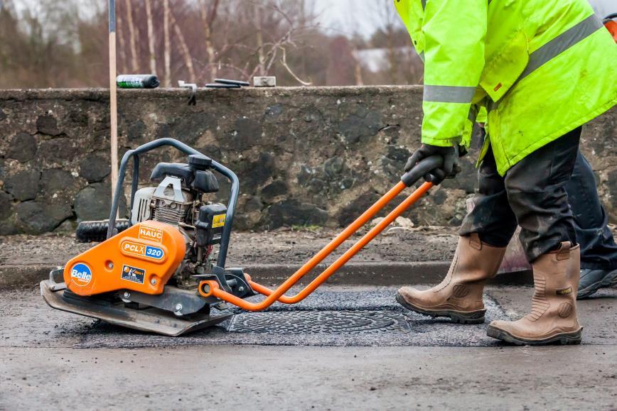

40 Compaction Over-banding May

41 Using Polymer Modified Mastic Asphalt to install Ironwork Manhole chamber top exposed Polymer modified mastic asphalt as bedding mortar May


42 Layer of engineering brick Installing second layer of polymer modified mastic asphalt as bedding May

43 Second layer of polymer modified mastic asphalt as bedding Placing frame and cover May


44 Polymer modified mastic asphalt placed as binder course Polymer modified mastic asphalt placed as surface course May

45 Completed installation May
1.3 It is recognised that the DCMS Guidance document significantly restricts the use of microtrenching. Recommendations 2 and 3 state:
 1. Introduction/Scope 1.1 A separate Specification, as a supplement to the Specification for Reinstatement of Openings in the Highway 3 rd Edition (England) (hereafter the SROH ), has been produced to
INSTARMAC PERMANENT COLD LAY SURFACING MATERIALS ULTRACRETE INSTANT ROAD REPAIR 6 MM
 H A P A S Instarmac Group plc Danny Morson Way Birch Coppice Business Park Dordon, Tamworth Staffordshire B78 1SE Tel: 01827 872244 Fax: 01827 874466 HAPAS Certificate e-mail: enquiries@instarmac.co.uk
Telecommunications Infrastructure
 Telecommunications Infrastructure Table of Contents Contents 1. INTRODUCTION... 2 2. DUCTING CAPACITY... 3 3. SUB DUCT SIZING... 4 4. DUCTING AND SUB DUCTING CONSTRUCTION AND COLOUR... 5 5. BUILDING ENTRANCE:...
ROAD PAVEMENTS GENERAL
 ROAD PAVEMENTS GENERAL Contents Clause Title Page 701 Pavement Construction... 2 702 Horizontal Alignments, Surface Levels and Surface Regularity of Pavement Courses... 2 703 Not Used... 4 704 Not Used...
HAPAS Roads and Bridges Roadtechs Specialist Products Ltd
 HAPAS Roads and Bridges Roadtechs Specialist Products Ltd Barondale Lane Topcroft, Bungay Norfolk NR35 2BE Tel: 01508 536360 Fax: 01508 536160 e-mail: info@roadtechs.net website: www.roadtechs.net ROADTECHS
ROADTECHS CRACK SEALING SYSTEMS FOR HIGHWAYS ROADFLEX FLEXIBLE INLAID CRACK SEALING SYSTEM FOR HIGHWAYS
 HAPAS Roadtechs Specialist Products Ltd APPROVAL INSPECTION TESTING CERTIFICATION Barondole Lane Topcroft Bungay Suffolk NR35 2BE Tel: 01508 536360 Fax: 01508 536160 TECHNICAL APPROVALS FOR CONSTRUCTION
SERIES 1100 KERBS, FOOTWAYS AND PAVED AREAS
 MANUAL OF CONTRACT DOCUMENTS FOR HIGHWAY WORKS VOLUME 1 THE SPECIFICATION FOR HIGHWAY WORKS SERIES 1100 KERBS, FOOTWAYS AND PAVED AREAS Contents Clause Title Page 1100 (02/17) General 2 #1101 Precast Concrete
Part 4 A. Supervising paving for road and footway works. What you need to know before work starts re materials to be used
 Part 4 A Supervising paving for road and footway works What you need to know before work starts re materials to be used 1 Documents relating to asphalt paving 1. BS doc, PD6691, The guide to specifying
TARMAC THIN SURFACING SYSTEMS FOR HIGHWAYS ULTIPAVE 10 D THIN SURFACING SYSTEM
 H A P A S Tarmac Trading Ltd Bickenhill Lane Solihull Birmingham B37 7BQ Tel: 0845 812 6400 Fax: 0845 812 6200 e-mail: enquiries@tarmac.com website: www.tarmac.com TARMAC THIN SURFACING SYSTEMS FOR HIGHWAYS
LAFARGE TARMAC THIN SURFACING SYSTEMS FOR HIGHWAYS. ULTIPHALT 10 mm D THIN SURFACING SYSTEM
 HAPAS Lafarge Tarmac Trading Ltd Bickenhill Lane Solihull Birmingham B37 7BQ Tel: 0845 812 6400 Fax: 0845 812 6200 e-mail: enquiries@lafargetarmac.com website: www.lafargetarmac.com LAFARGE TARMAC THIN
SECTION 3 Hartlid Range. Ultracrete. Ductile Iron Access Covers Page 82 Ductile Iron Gully Grates Page 86. Ironwork Reinstatement System Page 87
 SECTION 3 Hartlid Range Ductile Iron Access Covers Page 82 Ductile Iron Gully Grates Page 86 Ultracrete Ironwork Reinstatement System Page 87 www.burdens.co.uk 81 Introduction Burdens Limited, the UK s
Withdrawn. NRA Interim Advice Note 08/13. Specification and Notes for Guidance on the Use of Permanent Repair Material Systems.
 October 2013 NRA Interim Advice Note 08/13 Specification and Notes for Guidance on the Use of Permanent Repair Material Systems Withdrawn St. Martin s House, Waterloo Road, Dublin 4 Tel: +353 1 660 2511
CIP DENSIPHALT GROUTED MACADAM SURFACE COURSE CIP DENSIPHALT
 H A P A S Roads and Bridges CIP Densiphalt Ltd Unit 2, Ouse Road Bicton Industrial Estate Kimbolton Cambridgeshire PE28 0LW Tel: 01480 861880 Fax: 01480 861097 e-mail: sales@cipltd.co.uk website: www.cipltd.co.uk
HAPAS APPROVAL INSPECTION TESTING CERTIFICATION
 HAPAS APPROVAL INSPECTION TESTING CERTIFICATION Breedon Southern Ltd Breedon Quarry Main Street Breedon-on-the-Hill Derbyshire DE73 8AP Tel: 01332 694000 Fax: 01332 865402 TECHNICAL APPROVALS FOR CONSTRUCTION
DUCTILE IRON. Manhole Covers, Gratings & Surface Box
 DUCTILE IRON Manhole Covers, Gratings & Surface Box BS-EN-124 IS:1726 Quality Policy We are committed to produce quality Products (C.I., D.I., C.S. Valves, Pipes, Fittings, Manhole Covers, Surface box
TARMAC THIN SURFACING SYSTEMS FOR HIGHWAYS. ULTIPAVE 6 mm THIN SURFACING SYSTEM
 H A P A S Tarmac Trading Ltd Bickenhill Lane Solihull Birmingham B37 7BQ Tel: 0845 812 6400 Fax: 0845 812 6200 e-mail: enquiries@tarmac.com website: www.tarmac.com TARMAC THIN SURFACING SYSTEMS FOR HIGHWAYS
SPECIFICATION FOR PRECAST/ COMPOSITE CONCRETE FLOORS/ ROOF DECKS SECTION E60
 SPECIFICATION FOR SECTION E60 A 2007-09-26 S.W. Revision Date Issue Authorised By Approved for Issue SW Date 24.09.07 clarkebond Page 1 of 6 To be read with Preliminaries/ General Conditions. GENERAL 10
HAPAS Certificate Tel: Fax: /H271 website: Product Sheet 2
 FM Conway Ltd Conway house Vestry Road Sevenoaks Kent TN14 5EL Page 1 of 7 HAPAS Certificate Tel: 0208 636 8822 Fax: 0208 636 8827 17/H271 website: www.fmconway.co.uk Product Sheet 2 FM CONWAY ASPHALT
TARMAC THIN SURFACING SYSTEMS FOR HIGHWAYS ULTIFLEX 6 mm THIN SURFACING SYSTEM
 H A P A S Tarmac Trading Ltd Bickenhill Lane Solihull Birmingham B37 7BQ Tel: 0845 812 6400 Fax: 0845 812 6200 e-mail: enquiries@tarmac.com website: www.tarmac.com This Certificate relates to the ULTIFLEX
TARMAC THIN SURFACING SYSTEMS FOR HIGHWAYS. ULTIFLEX 14 mm THIN SURFACING SYSTEM
 H A P A S Tarmac Trading Ltd Bickenhill Lane Solihull Birmingham B37 7BQ Tel: 0845 812 6400 Fax: 0845 812 6200 e-mail: enquiries@tarmac.com website: www.tarmac.com TARMAC THIN SURFACING SYSTEMS FOR HIGHWAYS
TARMAC THIN SURFACING SYSTEMS FOR HIGHWAYS. ULTICOLOUR 6 mm THIN SURFACING SYSTEM
 H A P A S Tarmac Trading Ltd Bickenhill Lane Solihull Birmingham B37 7BQ Tel: 0845 812 6400 Fax: 0845 812 6200 e-mail: enquiries@tarmac.com website: www.tarmac.com TARMAC THIN SURFACING SYSTEMS FOR HIGHWAYS
RESIN FLOORING. To be read with Preliminaries/ General Conditions TYPE(S) OF FLOORING
 OF FLOORING") M12 To be read with Preliminaries/ General Conditions TYPE(S) OF FLOORING 110A - Primer reference: None or Altro Prime standard dependant on substrate - Resin flooring reference: Altro Grip 1mm slip-resistant
M12 To be read with Preliminaries/ General Conditions TYPE(S) OF FLOORING 110A - Primer reference: None or Altro Prime standard dependant on substrate - Resin flooring reference: Altro Grip 1mm slip-resistant
PRODUCT SHEET 1 DURAKERB HALF-BATTERED (HB2) KERB UNITS
 KERB UNITS") H A P A S Roads and Bridges Durakerb Ltd Old House Gorsey Lane, Coleshill Birmingham B46 1JU Tel: 01675 432109 Fax: 01675 432119 e-mail: info@durakerb.com website: www.durakerb.com Agrément Certificate
H A P A S Roads and Bridges Durakerb Ltd Old House Gorsey Lane, Coleshill Birmingham B46 1JU Tel: 01675 432109 Fax: 01675 432119 e-mail: info@durakerb.com website: www.durakerb.com Agrément Certificate
Integrated Manhole Ladder System
 Application: This innovative product has been designed to provide safe access and egress to precast concrete manholes and inspection chambers. It can also be used within any other underground concrete
BISON PRECAST FLOORING SPECIFICATION
 BISON PRECAST FLOORING SPECIFICATION 1.0 SCOPE OF THE SPECIFICATION 1.01 Relates to: This specification covers the design, manufacture and associated site work of the following types of floors:- Hollowcore
roofing ROOFING Design of the base ROOFING DETAILS
 DETAILS The general arrangement details and the principles to be followed at skirtings, upstands, abutments, verges, gutters and expansion joints are as details illustrated. SELECTION PARAMETERS It is
SERIES NG 1100 KERBS, FOOTWAYS AND PAVED AREAS
 MANUAL OF CONTRACT DOCUMENTS FOR HIGHWAY WORKS VOLUME 2 NOTES FOR GUIDANCE ON THE SPECIFICATION FOR HIGHWAY WORKS SERIES NG 1100 KERBS, FOOTWAYS AND PAVED AREAS Contents Clause Title Page NG 1101 General
Installation Guide DURABLE, VERSATILE, ECONOMICAL
 Installation Guide DURABLE, VERSATILE, ECONOMICAL 1 Installation Guide Installation - General Comments This information is intended only as a guide to best practice installation. The installation procedure
Drexus Pave Drain. Linear Channel. Water Management. Water Linear Management Drainage Design Guide Drexus Pave Drain Linear Drainage Channel
 Linear Channel Water Management Linear Channel Drexus Pave Drain Textured Silver Grey Textured Charcoal Textured Buff D400 Yorkstone, Scoutmoor Mid Grey Granite Silver Grey Granite Drexus Pave Drain Concrete
TUFFPAVE THIN SURFACING SYSTEMS FOR HIGHWAYS TUFFPAVE 10 MM THIN SURFACING SYSTEM
 H A P A S Hanson Quarry Products Europe Ltd Hanson House 14 Castle Hill Maidenhead Berkshire SL6 4JJ Tel: 01628 774100 e-mail: enquiries@hanson.com website: www.hanson.co.uk TUFFPAVE THIN SURFACING SYSTEMS
HAPAS Certificate 12/H190 website: Product Sheet 1
 Asphalt Research Technology, Inc d/b/a, The EZ Street Company 13611 S. Dixie Hwy, Suite 430 Miami Florida 33176 USA Tel: 00 1 305 663 3090 Fax: 00 1 305 663 0832 Page 1 of 7 HAPAS Certificate e-mail: sales@ezstreetasphalt.com
Reassessed Streetworks Excavation and Reinstatement ( )
") Reassessed Streetworks Excavation and Reinstatement (6156-24) Qualification unit handbook for centres www.cityandguilds.com October 2015 Version 4.0 Ov 0 Reassessed Streetworks Excavation and Reinstatement
Reassessed Streetworks Excavation and Reinstatement (6156-24) Qualification unit handbook for centres www.cityandguilds.com October 2015 Version 4.0 Ov 0 Reassessed Streetworks Excavation and Reinstatement
JOINTMASTER CRACK SEALING SYSTEM FOR HIGHWAYS JOINTMASTER IMP (GRADE H) INLAID CRACK SEALING SYSTEM FOR HIGHWAYS
 INLAID CRACK SEALING SYSTEM FOR HIGHWAYS") Rhino Asphalt Solutions Ltd Suite S8 Waterside Centre North Street Lewes East Sussex BN7 2PE For internal use only HAPAS Certificate Tel: 01273 402 900 e-mail: info@rhino-uk.com 09/H149 website: www.rhino-uk.com
Rhino Asphalt Solutions Ltd Suite S8 Waterside Centre North Street Lewes East Sussex BN7 2PE For internal use only HAPAS Certificate Tel: 01273 402 900 e-mail: info@rhino-uk.com 09/H149 website: www.rhino-uk.com
FERFA GUIDE TO FLOWABLE POLYMER SCREEDS AS UNDERLAYMENTS FOR RESIN FLOOR FINISHES
 FERFA GUIDE TO FLOWABLE POLYMER SCREEDS AS UNDERLAYMENTS FOR RESIN FLOOR FINISHES FeRFA Guidance Note No. 8 www.resdev.co.uk 1 CONTENTS 1. Introduction... 3 1.1 Scope... 3 2. SELECTION Criteria... 3 2.1.
TRUSTSEAL HIGH-FRICTION SURFACING SYSTEM KEYGRIP EPOXY 924
 HAPAS Roads and Bridges Trustseal Ltd Unit 10 Southfield Industrial Estate Southfield Lane Whitwell, Worksop Nottinghamshire S80 4NW Tel: 01909 722662 Fax: 01909 720228 e-mail: info@trustseal.co.uk website:
The Role of the Resident Engineer. Liam Geoghegan MSc
 The Role of the Resident Engineer Liam Geoghegan MSc Inroduction Liam Geoghegan, RPS Consulting Engineers Experience in Road Construction Projects since 1991 I have worked for Local Authorities, Consulting
INTERIM ADVICE NOTE 169/12 Revision 1. Temporary Cover Plates over Bridge Expansion Joints
 INTERIM ADVICE NOTE 169/12 Temporary Cover Plates over Bridge Expansion Joints Summary This IAN highlights the issues to be considered when using temporary cover plates. IAN 169/12 Page 1 of 6 July 2013
ACO Water Management: Urban + Landscape
 ACO Water Management: Urban + Landscape Uniclass L567 CI/SfB (7.) EPIC E48 ACO Universal Channel Gully 4 Provides fast and simple connection for all ACO channels up to 00mm bore width 4 Modular system
JOINTMASTER CRACK SEALING SYSTEMS FOR HIGHWAYS JOINTMASTER JMB FLEXIBLE INLAID CRACK SEALING SYSTEM FOR HIGHWAYS
 Rhino Asphalt Solutions Ltd Suite S8 Waterside Centre North Street Lewes East Sussex BN7 2PE Tel: 01273 402 900 e-mail: info@rhino-uk.com website: www.rhino-uk.com For internal use only JOINTMASTER CRACK
3.5 What guidance is there?
 3.5 What guidance is there? 3.5.1 General A number of specifications and codes of practice for the use of road plates were identified during the literature review. The main points from these documents
Manufacturing standard
 CI/SfB I I (52.5) I f I I Landscaping Charcon Highway OHS61759 FM96927 EMS96928 Highway is a high capacity combined kerb and drainage system, offering a cost-effective all-in-one alternative to conventional
PRODUCT DATA SHEET Sikadur -31 DW
 PRODUCT DATA SHEET 2-PART EPOXY ADHESIVE WITH APPROVAL FOR DRINKING WATER CONTACT DESCRIPTION 2-part adhesive and repair mortar, based on epoxy resins and special fillers which has been specially formulated
BELMURO WALL SYSTEM INSTALLATION GUIDE
 BELMURO WALL SYSTEM INSTALLATION GUIDE TABLE OF CONTENTS TABLE OF CONTENTS... 1 SYSTEM DESCRIPTION... 2 DRY STACK SYSTEM: INSTALLATION GUIDE... 5 GEOGRID WALL SYSTEM: INSTALLATION GUIDE... 9 MASONRY WALL
System Data Sheet. Permatrack Bridge Surfacing Product Scope. April 2016
 System Data Sheet April 2016 Permatrack Bridge Surfacing Product Scope This product data sheet relates to Permatrack Bridge Surfacing for use as a surface course, and as a protection layer on new and maintenance
TECHNICAL DATA SHEET SIKADUR 31 CF NORMAL 6KG
 TECHNICAL DATA SHEET SIKADUR 31 CF NORMAL 6KG Sikadur 31 is a two component solvent-free, cold cure, thixotropic epoxy adhesive suitable for damp and dry substrates. Available in two grades - Normal and
STAR URETECH HIGH-FRICTION SURFACING SYSTEM URETECH HFS
 HAPAS Roads and Bridges Star Uretech Ltd Enterprise House Hollin Bridge Street Blackburn Lancashire BB2 4AY Tel: 01254 663444 Fax: 01254 681886 e-mail: info@star-uretech.com website: www.star-uretech.com
Technical Manual - Section 7 Lytag LWA Roof and Floor Screeds
 Uniclass L526+L5371:P224 EPIC E35+E451:X223 CI/SfB (43)+(47) Pq7 Technical Manual - Section 7 Lytag LWA Roof and Floor Screeds Introduction... 2 Weight saving... 3 Strength... 4 Shrinkage... 4 Thermal
Specification for Installation of Quadbox Modular Access Chambers JMF102, JMF104, JMF106
 Specification for Installation of Quadbox Modular Access Chambers JMF102, JMF104, JMF106 Page 1 of 8 INDEX 1 General information...3 2 Safety...3 3 Installation Procedure...3 3.1 Chamber Depth... 4 3.2
Specification for Road Works Series Road Restraints Systems (Vehicle and Pedestrian)
") Specification for Road Works Series 400 - Road Restraints Systems (Vehicle and Pedestrian) CC-SPW-00400 March 2013 CC Construction & Commissioning Standards TRANSPORT INFRASTRUCTURE IRELAND (TII) PUBLICATIONS
Specification for Road Works Series 400 - Road Restraints Systems (Vehicle and Pedestrian) CC-SPW-00400 March 2013 CC Construction & Commissioning Standards TRANSPORT INFRASTRUCTURE IRELAND (TII) PUBLICATIONS
TECHNICAL DATA SHEET SIKADUR 31 RAPID 1.2KG
 TECHNICAL DATA SHEET SIKADUR 31 RAPID 1.2KG Sikadur -31 is a two component solvent free, cold cure, thixotropic epoxy adhesive suitable for damp and dry substrates. Available in two grades - 31CF Normal
CHAPTER 10: Finishes CONTENTS 10.1 PLASTERWORK 10.2 SECOND AND THIRD FIX FINISHES. Chapter 10
 CONTENTS 10.1 PLASTERWORK 10.2 SECOND AND THIRD FIX FINISHES 283 Chapter 10 FUNCTIONAL REQUIREMENTS FUNCTIONAL REQUIREMENTS 10.1 PLASTERWORK Workmanship i. All workmanship must be within the tolerances
Construction Specification for Utility Adjustments
 Engineering & Construction Services Division Standard Specifications for Road Works TS 4.50 September 2017 for Utility Adjustments Table of Contents TS 4.50.01 SCOPE... 2 TS 4.50.02 REFERENCES... 2 TS
Suggested laying methods for STONE pavers
 Suggested laying methods for STONE pavers These suggestions are a guide only and should be used in addition to the relevant Australian Standards for trade practices. It is to be noted that installation
Unit 9 Reinstatement of modular surfaces and concrete footways
 This unit covers the requirements that you must meet when reinstating modular surfaces and concrete. You must ensure that you act in accordance with all current specifications and procedures and that you
BEAM & BLOCK SYSTEM. 108mm. 175mm Deep (160mm) Wide Beam. 160mm
 Wide Beam. 160mm") RH F RACKHAM HOUSEFLOORS BEAM & BLOCK SYSTEM BEAM & BLOCK SYSTEM 1. THE BEAMS 60mm 108mm 90mm 75mm 75mm 100mm 175mm 100mm 175mm 125mm 100mm 175mm Deep Beam 175mm Deep (160mm) Wide Beam 225mm Deep Beam
RH F RACKHAM HOUSEFLOORS BEAM & BLOCK SYSTEM BEAM & BLOCK SYSTEM 1. THE BEAMS 60mm 108mm 90mm 75mm 75mm 100mm 175mm 100mm 175mm 125mm 100mm 175mm Deep Beam 175mm Deep (160mm) Wide Beam 225mm Deep Beam
TECHNICAL SPECIFICATION FOR CURED-IN-PLACE MANHOLE REHABILITATION LINER SYSTEM
 TECHNICAL SPECIFICATION FOR CURED-IN-PLACE SYSTEM PART 1 GENERAL 1.01 SCOPE OF WORK Furnish all materials, labor, equipment, tools and required incidentals for providing and installing a resin impregnated
CHAPTER 10: Finishes CONTENTS 10.1 PLASTERWORK ND AND 3 RD FIX FINISHES
 CONTENTS 10.1 PLASTERWORK 10.2 2 ND AND 3 RD FIX FINISHES FUNCTIONAL REQUIREMENT 10.1 Plasterwork Workmanship Design Technical Manual TS-011-09-010412 i. All workmanship must be within defined tolerances
CONCRETE TILE PAVERS
 Section 32 14 13 CONCRETE TILE PAVERS (1995 MasterFormat Section 02780) Note: This guide specification for the U.S. is for the installation of concrete tile paving units whose thickness are less than the
Micro-trench Reinstatement
 TECHNICAL ADVICE NOTE 11-09 Micro-trench Reinstatement 1. Introduction Fibre to the property (FTTP) or Fibre to the Home (FTTH) initiatives in many countries around the world have created the requirement
Use of BS 5400: Part 4: 1990
 Volume 1 Section 3 Part 1 NRA BD 24/00 The Design of Concrete Road Bridges and Structures Use of BS 5400: Part 4: 1990 December 2000 St. Martin s House, Waterloo Road, Dublin 4. Tel:+353 1 660 2511 Fax
RONACRETE BEDDING MORTARS RONABOND BEDDING MORTAR
 Ronacrete Ltd Ronac House Flex Meadow Merring Way Harlow Essex CM19 5TD Tel: 01279 638700 Fax: 01279 638701 e-mail: techweb@ronacrete.co.uk website: www.ronacrete.co.uk APPROVAL INSPECTION TESTING CERTIFICATION
Specification for Road Works Series Waterproofing for Concrete Structures
 Specification for Road Works Series 2000 - Waterproofing for Concrete Structures CC-SPW-02000 December 2010 CC Construction & Commissioning Standards TRANSPORT INFRASTRUCTURE IRELAND (TII) PUBLICATIONS
ULTIMAT GUIDE FOR APPROVED CONTRACTORS
 ULTIMAT GUIDE FOR APPROVED CONTRACTORS November 2015 ULTIMAT GUIDE FOR APPROVED CONTRACTORS CONTENTS Introduction 1. Approval of Laying Contractors 1.1 Preparation for Approval 1.2 Initial Contract 1.3
For Bridge Decks, Buildings and Construction.
 For Bridge Decks, Buildings and Construction www.stirlinglloyd.com INNOVATION AND EXPERIENCE Since 1970 Stirling Lloyd has been involved in the development, manufacture and application of specialist membrane
SECTION 503 TEMPORARY PAVEMENT RESTORATION
 SECTION 503 TEMPORARY PAVEMENT RESTORATION 503-1 DESCRIPTION: This work consists of furnishing, placing, compacting, and maintaining a temporary pavement surface suitable for driving in accordance with
Supaflow HF Grout. Dual Expansion Class C Grout. Description. Areas of application. Features
 Supaflow HF Grout Dual Expansion Class C Grout Description Supaflow HF is a free flowing cement based grout offering high performance and non-shrink characteristics. This product is suitable for pumping
KU Design Guidelines APPENDIX II PERMEABLE BITUMINOUS PAVEMENT
 PERMEABLE BITUMINOUS PAVEMENT PART 1: GENERAL 1.01. RELATED DOCUMENTS: A. Drawings and general provisions of Contract, including Special Requirements General Conditions and Division 1 Specifications Sections,
asphalt applications Asphalt surfacings for high stress areas mpa asphalt Asphalt Information Service Mineral Products Association
 asphalt applications 6 Asphalt surfacings for high stress areas Asphalt Information Service mpa asphalt November 2009 Mineral Products Association Introduction Information Sheet 2 in this series, Construction
Bison Precast Flooring Specification
 Page: 1 of 4 1.0 SCOPE OF THE SPECIFICATION 1.01 Floor types: This specification covers the design, manufacture and associated site work for the following floor types; Hollow core floors Composite hollow
Reinforced concrete slot channel
 Applicable Bodies of Rules: DIN EN 1433»Drainage channels for vehicular and pedestrian areas«din 19580»Drainage channels for vehicular and pedestrian areas«the following laying instructions are general
EDGE RESTRAINT SYSTEM
 EDGE RESTRAINT SYSTEM Whether its decorative block paving or precast flags, alternate edge restraint systems are taking the world of paving by storm and IrandiPRO is South Africa s first such system. Proudly
Product Data Sheet Sikadur -31 CF Normal Product Description Uses ruction Const Characteristics / Advantages
 Construction Product Data Sheet Edition 02/12/2013 Identification no: 02 04 02 03 001 0 000039 Sikadur -31 CF Normal 2-part thixotropic epoxy adhesive Product Description Uses Characteristics / Advantages
CHESHIRE EAST COUNCIL. Highways Service. Abridged Conditions, Requirements and Specification of Workmanship and Materials for the Construction of
 !"#$!%& '( )*& CHESHIRE EAST COUNCIL Highways Service Abridged Conditions, Requirements and Specification of Workmanship and Materials for the Construction of Highways Act 1980: Section 184. C O N T E
TECHNICAL INFORMATION SCREED
 TECHNICAL DATA SHEET SCREED Ver Nov 2015 TECHNICAL INFORMATION SCREED Product Data Sheet No. 110/01 INTRODUCTION Tarmac ready-to-use cement sand levelling screed is a correctly proportioned factory produced
Author: M Shaw, Sika Limited. Construction. A Guide to the Concrete Repair European Standards BS EN 1504 Series
 Author: M Shaw, Sika Limited A Guide to the Concrete Repair European Standards BS EN 1504 Series 1 Contents Section Heading Page Introduction 3 1.0 Overview of BS EN 1504 Documents 4 2.0 BS EN 1504 Principles
GUARANTEED ASPHALT LIMITED
 GUARANTEED ASPHALT LIMITED GuaraTEC Installation Guide Installing our fully bonded hot melt system. 2016 Barratt Homes, Osiers Road Guaranteed Asphalt Limited 2 Mercury Way, London, SE14 5RR, 020 7277
SUGGESTED MANHOLE FRAME SEALING SPECIFICATION (Rehabilitation)
") PART 1 GENERAL SUGGESTED MANHOLE FRAME SEALING SPECIFICATION (Rehabilitation) 1.01 SCOPE This specification includes the materials and procedures required for the internal sealing of the frame-chimney
PART 1 GENERAL SUGGESTED MANHOLE FRAME SEALING SPECIFICATION (Rehabilitation) 1.01 SCOPE This specification includes the materials and procedures required for the internal sealing of the frame-chimney
The work required for this project includes, but is not limited to, the following items, not listed in order of execution.
 ESTIMATE OF QUANTITIES SPECIFICATIONS Construction Specifications: South Dakota Standard Specifications for Roads and Bridges, 2004 Edition and Required Provisions, Supplemental Specifications and/or Special
SERIES 1100 KERBS, FOOTWAYS AND PAVED AREAS
 MANUAL OF CONTRACT DOCUMENTS FOR HIGHWAY WORKS VOLUME 1 THE SPECIFICATION FOR HIGHWAY WORKS SERIES 1100 KERBS, FOOTWAYS AND PAVED AREAS Contents Clause Title Page 1100 (02/17) General 2 #1101 Precast Concrete
Product Data Sheet Product n Description Uses tio tru Characteristics / C Advantages Tests Approval / Standards
 Product Data Sheet Edition 01/02/2012 Identification no: 01 04 02 03 001 0 000039 Sikadur -31 CF Normal 2-part thixotropic epoxy adhesive Construction Product Description Uses Characteristics / Advantages
PRODUCT DATA SHEET Sikadur 31 CF Normal (formerly Sikadur 731)
") PRODUCT DATA SHEET (formerly Sikadur 731) 2-part Thixotropic Epoxy Adhesive PRODUCT DESCRIPTION Sikadur-31 CF Normal is a solvent-free, moisture tolerant, thixotropic, structural two part adhesive and
PRODUCT DATA SHEET (formerly Sikadur 731) 2-part Thixotropic Epoxy Adhesive PRODUCT DESCRIPTION Sikadur-31 CF Normal is a solvent-free, moisture tolerant, thixotropic, structural two part adhesive and
FUNCTIONAL REQUIREMENTS
 FUNCTIONAL REQUIREMENTS FUNCTIONAL REQUIREMENTS 7.6 BALCONIES Workmanship i. All workmanship must be within the tolerances defined in Chapter 1 of this manual. ii. All work is to be carried out by a technically
GROUNDtrax GROUNDGRIDZ
 INSTALLATION GUIDE The product is asymmetric and must be lifted by placing the hands on the diagonally opposed corners of the central paver (as shown). 1. Place grids onto the prepared well consolidated
Mini Beany. Combined Kerb and Drainage System. Water Linear Management Drainage Design Guide Mini Beany Linear Drainage Channel
 Mini Beany, Conservation, Bedford Conservation Silver Grey Standard Grey Mini Beany Combined Kerb and Drainage System Mini Beany is a low to medium capacity combined kerb and drainage system which evolved
SAFETY SYSTEM. G-Deck Consideration. Manual Handling
 INTRODUCTION The G-Deck load deck system is a high strength, low cost access platform which is quick to erect, durable and flexible enough to meet your site access needs. Safety is a priority and G-Deck
Installation instructions. MEA Drainage systems
 80 210 400 General installation instructions Our installation instructions are general suggestions only. The planners must ascertain whether site conditions necessitate special requirements as regards
Safety Method Statement External Works
 Description of Work and Location EXTERNAL WORKS A.Generally Preambles for other Sections of work shall apply equally to this section where applicable. B.Weed Killer The weed killer to excavations to be
F10. BRICK/BLOCK WALLING To be read with Preliminaries/General conditions. TYPES(S) OF WALLING 110 CLAY FACING BRICKWORK SHALL BE:
 OF WALLING 110 CLAY FACING BRICKWORK SHALL BE:") F10 BRICK/BLOCK WALLING To be read with Preliminaries/General conditions. TYPES(S) OF WALLING 110 CLAY FACING BRICKWORK SHALL BE: Product Name: Olde English Grey Size: 215x102x65mm Manufacturer and reference:
F10 BRICK/BLOCK WALLING To be read with Preliminaries/General conditions. TYPES(S) OF WALLING 110 CLAY FACING BRICKWORK SHALL BE: Product Name: Olde English Grey Size: 215x102x65mm Manufacturer and reference:
B. Reinforcing. Materials shall be as specified in Section 2000 Concrete or as indicated on the plans.
 SECTION 1400 - CONCRETE PAVEMENT 1401 SCOPE. This section governs the furnishing of all labor, equipment, tools, and materials and the performance of all work necessary to construct concrete pavement.
CONSTRUCTION SPECIFICATION FOR INSTALLATION OF ELECTRICAL CHAMBERS
 ONTARIO PROVINCIAL STANDARD SPECIFICATION OPSS.PROV 602 NOVEMBER 2017 CONSTRUCTION SPECIFICATION FOR INSTALLATION OF ELECTRICAL CHAMBERS TABLE OF CONTENTS 602.01 SCOPE 602.02 REFERENCES 602.03 DEFINITIONS
CONSTRUCTION SPECIFICATION FOR CONCRETE PAVEMENT AND CONCRETE BASE
 ONTARIO PROVINCIAL STANDARD SPECIFICATION METRIC OPSS 350 MARCH 1998 CONSTRUCTION SPECIFICATION FOR CONCRETE PAVEMENT AND CONCRETE BASE 350.01 SCOPE 350.02 REFERENCES 350.03 DEFINITIONS TABLE OF CONTENTS
Joint Free Slabs On Grade Website:
 Joint Free Slabs On Grade Website: www.jointfreeslabs.com Specification Revised March 2014 Warwick Colefax Robert Colefax Phone (02) 9999 6688 Phone (07) 4051 9466 Fax (02) 9999 6680 Fax (07) 4051 9477
BITUMEN-SET PRECAST CONCRETE PAVING SLABS
 SECTION 32 14 13.16 BITUMEN-SET PRECAST CONCRETE PAVING SLABS (1995 MasterFormat Section 02784) NOTE: This guide specification is the U.S. for concrete paving slabs adhered with a neoprene mastic to a
Resin Bound and Bonded Surfacing. RonaDeck UV Rubber Granule Tree Pit Base. Resin bound rubber granule porous tree pit system.
 FEATURES SuDS compliant highly permeable UV stable non yellowing resin includes recycled rubber granules alternative to tree grilles installed by approved contractors design can accommodate some tree growth
WAVIN ROAD GULLIES. Date of First issue: 16 April 2014 Brian Chamberlain Claire Curtis-Thomas
 HAPAS Wavin Ltd Parsonage Way Chippenham Wiltshire SN15 5PN Tel: 01249 766600 Fax: 01249 443286 e-mail: info@wavin.co.uk website: www.wavin.co.uk WAVIN ROAD GULLIES APPROVAL INSPECTION TESTING CERTIFICATION
Requirements for Measuring and Pricing of Structural Concrete
 Requirements for Measuring and Pricing of Structural Concrete October 2016 TRANSPORT INFRASTRUCTURE IRELAND (TII) PUBLICATIONS About TII Transport Infrastructure Ireland (TII) is responsible for managing
9 Revision B
 JJI-JOIST TECHNICAL BULLETIN SUBJECT: Ground Floor Design & Restraint Bulletin Number: Date Issued: Sheet 1 of 11 Introduction When designing the ground floor of a residential dwelling using I-Joists,
F10. BRICK/BLOCK WALLING To be read with Preliminaries/General conditions. TYPES(S) OF WALLING 110 CLAY FACING BRICKWORK SHALL BE:
 OF WALLING 110 CLAY FACING BRICKWORK SHALL BE:") F10 BRICK/BLOCK WALLING To be read with Preliminaries/General conditions. TYPES(S) OF WALLING 110 CLAY FACING BRICKWORK SHALL BE: Product Name: Pre War Common Size: 215x102x65mm Manufacturer and reference:
F10 BRICK/BLOCK WALLING To be read with Preliminaries/General conditions. TYPES(S) OF WALLING 110 CLAY FACING BRICKWORK SHALL BE: Product Name: Pre War Common Size: 215x102x65mm Manufacturer and reference:
CONSTRUCTION SPECIFICATION FOR THE INSTALLATION OF ELECTRICAL CHAMBER
 ONTARIO PROVINCIAL STANDARD SPECIFICATION METRIC OPSS 602 MARCH 1993 CONSTRUCTION SPECIFICATION FOR THE INSTALLATION OF ELECTRICAL CHAMBER 602.01 SCOPE 602.02 REFERENCES 602.05 MATERIALS TABLE OF CONTENTS
CAPRICORN MUNICIPAL DEVELOPMENT GUIDELINES PRECAST BOX CULVERTS CONSTRUCTION SPECIFICATION
 CAPRICORN MUNICIPAL DEVELOPMENT GUIDELINES C222 CONSTRUCTION SPECIFICATION CAPRICORN MUNICIPAL DEVELOPMENT GUIDELINES C222 ISSUE: NO:3 July 2018 TABLE OF CONTENTS CLAUSE CONTENTS PAGE GENERAL... 2 C222.01