Possible solution to past CM examination question. Question 3 - January Temporary pedestrian bridge. by Saprava Bhattacharya
|
|
|
- Meghan Baldwin
- 5 years ago
- Views:
Transcription
.")
1 Possible solution to past CM examination question Question 3 - January 2015 Temporary pedestrian bridge by Saprava Bhattacharya The information provided should be seen as an interpretation of the brief and a possible solution to a past question offered by an experienced engineer with knowledge of the examiners expectations (i.e. it's an individual's interpretation of the brief leading to one of a number of possible solutions rather than the definitive "correct" or "model" answer).
2 Chartered Membership Examination 9 Question 3. Temporary pedestrian bridge Client s requirements 1. A temporary pedestrian bridge is required to provide access from the shore to an existing jetty serving passenger ferries: see Figure Q3. The temporary bridge is needed while the jetty is extended, putting the permanent access bridge out of use. Access for fishermen s boats is required under the temporary bridge. 2. The tidal range is 2.0m, from +0.5m high water to 1.5m low water. Datum is Mean Sea Level (MSL). The bridge is to be 150m long and to provide a 4.0m clear width for pedestrians. The jetty is 100m away from the shore at low water. A minimum clearance of 3.5m is required under the bridge at all states of the tide, over an uninterrupted length of 50.0m and a second uninterrupted length of 20m within the 100m distance between the jetty and shore. 3. No temporary or permanent foundations may be installed closer than 75.0m to the jetty. The client advises that the existing jetty is capable of supporting unfactored loads of 500kN vertically and 250kN laterally in both horizontal directions from the temporary bridge. The existing jetty deck level is +4.5m above MSL. 4. In the 50.0m length of bridge over the tidal zone of the shore, no construction may leave any footprint after the bridge is removed. 5. All existing services should remain uninterrupted during the construction, use and removal of the bridge. There is a 30.0m-high electricity transmission tower and line close to the proposed bridge which will remain live throughout the construction, use and removal of the bridge. Imposed loading 6. Live load on bridge deck. 5.0kN/m 2 Site conditions 7. The site is located in the open sea. Basic wind speed at sea level is 46.0m/s based on a 3-second gust; the equivalent mean hourly wind speed is 23.0m/s. 8. Ground Conditions Sea bed 30m below datum Stiff clay, C = 200kN/m 2 30m - depth Rock, characteristic compressive strength 1,000kN/m 2 Omit from consideration 9. Longitudinal imposed loading. SECTION 1 a. Prepare a design appraisal with appropriate sketches indicating two distinct and viable solutions for the proposed structure. Indicate clearly the functional framing, load transfer and stability aspects of each scheme. Identify the solution you recommend, giving reasons for your choice. b. After the completion of the design the client advises that a mistake was made in the calculation of the jetty load capacity, and the correct values are 50% of those previously advised in both the horizontal and vertical directions. Write a letter to your client advising of the implications this would have on your design and ways in which the design could be modified. SECTION 2 For the solution recommended in Section 1(a): c. Prepare sufficient design calculations to establish the form and size of all the principal structural elements including the foundations. d. Prepare general arrangement plans, sections and elevations to show the dimensions, layout and disposition of the structural elements and critical details for estimating purposes. e. Prepare a detailed method statement for the safe construction of the works and an outline construction programme. (50 marks) (40 marks) (10 marks) (50 marks) (20 marks) (20 marks) (10 marks)
3
4 Question 3. Temporary pedestrian bridge Question 3 Client s requirements 1. A temporary pedestrian bridge is required to provide access from the shore to an existing jetty serving passenger ferries: see Figure Q3. The temporary bridge is needed while the jetty is extended, putting the permanent access bridge out of use. Access for fishermen s boats is required under the temporary bridge. 2. The tidal range is 2.0m, from +0.5m high water to 1.5m low water. Datum is Mean Sea Level (MSL). The bridge is to be 150m long and to provide a 4.0m clear width for pedestrians. The jetty is 100m away from the shore at low water. A minimum clearance of 3.5m is required under the bridge at all states of the tide, over an uninterrupted length of 50.0m and a second uninterrupted length of 20m within the 100m distance between the jetty and shore. 3. No temporary or permanent foundations may be installed closer than 75.0m to the jetty. The client advises that the existing jetty is capable of supporting un-factored loads of 500kN vertically and 250kN laterally in both horizontal directions from the temporary bridge. The existing jetty deck level is +4.5m above MSL. 4. In the 50.0m length of bridge over the tidal zone of the shore, no construction may leave any footprint after the bridge is removed. 5. All existing services should remain uninterrupted during the construction, use and removal of the bridge. There is a 30.0m-high electricity transmission tower and line close to the proposed bridge which will remain live throughout the construction, use and removal of the bridge. Imposed loading 6. Live load on bridge deck. 5.0kN/m2 Site conditions 7. The site is located in the open sea. Basic wind speed at sea level is 46.0m/s based on a 3-second gust; the equivalent mean hourly wind speed is 23.0m/s. 8. Ground Conditions Sea bed 30m below datum Stiff clay, C = 200kN/m2 30m - depth Rock, characteristic compressive strength 1,000kN/m2 Omit from consideration 9. Longitudinal imposed loading. SECTION 1 (50 marks) a. Prepare a design appraisal with appropriate sketches indicating two distinct and viable solutions for the proposed structure. Indicate clearly the functional framing, load transfer and stability aspects of each scheme. Identify the solution you recommend, giving reasons for your choice. (40 marks) b. After the completion of the design the client advises that a mistake was made in the calculation of the jetty load capacity, and the correct values are 50% of those previously advised in both the horizontal and vertical directions. Write a letter to your client advising of the implications this would have on your design and ways in which the design could be modified. (10 marks) SECTION 2 (50 marks) For the solution recommended in Section 1(a): c. Prepare sufficient design calculations to establish the form and size of all the principal structural elements including the foundations. (20 marks) d. Prepare general arrangement plans, sections and elevations to show the dimensions, layout and disposition of the structural elements and critical details for estimating purposes. (20 marks) e. Prepare a detailed method statement for the safe construction of the works and an outline construction programme. (10 marks)

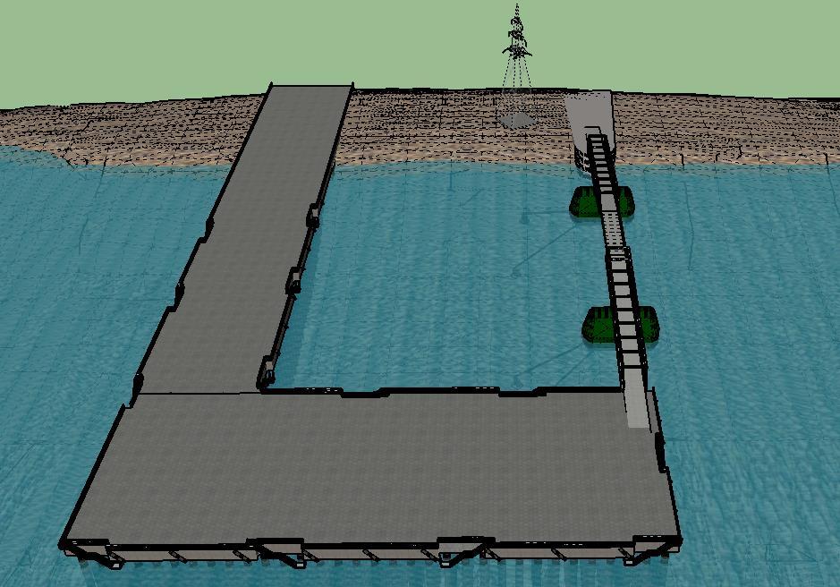
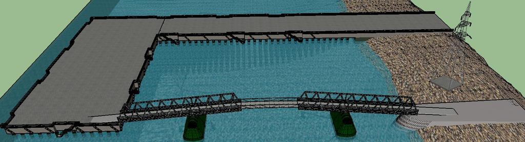
5 Introduction: Figures 1 and 2 show the site in three dimension Figure 1: Front View

6 Figure 2: side view This is a question where engineers are expected to think outside the box to come up with a very simple solution for a complicated problem and not the other way round. This was a real life problem. There are plenty of jetty out there for which similar situation could arise at any point of their service life.

.")

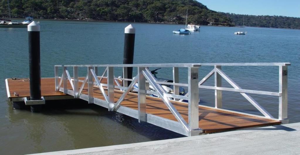
7 Looking at the client s requirements and the description of the site the only simple solution to the problem is nothing but a pedestrian walkway supported by floating barges at appropriate distance. One of the wellknown examples of floating bridge is the temporary bridge prior to construction of present Howrah Bridge at the capital city of Bengal state of India named Kolkata (Figure 3 and 4). Figure 3 Figure 4 Figure 5 Another example of an existing Floating foot bridge is Canary Warf Bridge (Figure 5) A simple pedestrian access to a small jetty is a possible way to join two approach trusses to overcome such problem as shown in Figure 6 below. This type of structure could be a joiner of two Trusses from either end as shown in the solutions shown through figure 7 and further.
8 Figure 6
9 Solution 1 Simple truss bridge dropped on top of Pontoons (spans 25m 55m & 25m) resting on Jetty on one end and on temporary embankment at the other end. This solution is the easiest. Simply supported truss bridges supported on pontoons / floating barges with appropriate overhang to support a simply supported dropping span in between, the basic cantilever bridge concept. Span adjustment could be such that the clearance envelops are compiled, as well as the reactions on the existing jetty never exceed as mentioned in client s brief. 3D model in figure 9 to 12 as well as sketches in figure 7 & 8 is self- explanatory to demonstrate the simplest possible solution to this particular problem. If required these floating pontoon / barge can be tied back to some form of anchors on seabed. This particular will be the only solution which can really be considered as a pure temporary solution. Figure 7 Cross sectional view of the proposed solution 1
10 Figure 8 Long sectional view of the proposed solution 1 In the following figures 9 to 12 three dimensional views of the proposed simple solution should be sufficiently self-explanatory to demonstrate its appropriateness.
11 Figure 9

12 Figure 11 Figure 10

13 Figure 12 Though the question asks candidates to propose two solutions for a temporary bridge structure, truss superstructure were inevitable. To make them fully distinct from each other, it was essential to propose two truss bridge superstructures whose supporting arrangements are significantly different from each other so that the load path is different.
14 Solution 2 To be a complete distinct as well a temporary solution - one half of Tokyo Gate Bridge with suspended span can easily be a discarded but feasible solution. The length of the suspended span to be decided based on its reaction to the existing jetty. Precast concrete deck may be used on top of the under slung truss for the approach span to balance some permanent load and avoid any possible uplift at the end abutment when there isn t any live load. Although both the proposed solutions are based on cantilever bridge concept but the load path and structural configuration of both the solutions are totally different in spite of the same material being used. Figure 13 and followed by other figures of three dimensional representations are self- sufficient to demonstrate its appropriateness for this particular problem. Figure 13 Long sectional view of the proposed solution 2


15 Figure 14 Figure 15

16 Figure 16 Comparison of two options: Looking at the two proposals it is obvious that the first solution is much more appropriate to the problem for many reasons. For Example: Purely temporary structure, least construction period and disruption to the users, much more economical, and many more.
17 Letter writing: Controlling support reactions to the given value itself is one of the major challenges for this question. Unless span and structural arrangements are appropriately proposed like the above two solutions it is impossible to meet the given criterion. Therefore it is inevitable to come up with an arrangement which will comply with allowable reaction forces. For the chosen solution it is essential to establish what could be the reactions on the existing Jetty with different patterns of live loading. As per the question, the restriction is on vertical positive reaction, but not on the negative reaction. Letter criterion is also in the same line, hence should be dealt accordingly. Calculation: First aim of this part should be to demonstrate the vertical reaction on the existing Jetty 4m wide 5kN/m 2 LL => 20kN/m. Considering, a conservative approach all other possible vertical loads add up to another 20kN/m allows maximum span of 25m simply supported. For any overhang superstructure for a cantilever bridge arrangement as considered, the reaction at the support on top of the existing jetty can never reach 500kN. In fact an Influence line diagram for the end support reaction will confirm that. L 3/5L L 3/5L L The main trusses at either end will have bottom cord in compression whereas in the top cord of the suspended span. The compression force in them can easily be worked out from the BMD of the above idealised single line beam model and designed accordingly. Use of RHS could easily be adopted.

18 Drawings Further improvement in figure 7 and 8 and adding few cross sections of the bridge superstructures could be sufficient as general arrangement drawing for the chosen solution. 4000mm Pontoon / Floating Barge Figure 17: Typical Through truss bridge superstructure cross section
19 Method of Statement: For the chosen solution, construction activity at site is negligible. Other than the construction of approach embankment there is hardly any construction activity left for this. However fabrication, transportation and erection of truss bridge superstructure especially on top of pontoon or floating barge should be highly important aspect of this method of statement. Hence the Bar chart on construction programme must be prepared with extra amount of care.
Possible solution to past CM examination question. Question 3 - April Footbridge over a waterfall. by Saprava Bhattacharya
 Possible solution to past CM examination question Question 3 - April 2013 Footbridge over a waterfall by Saprava Bhattacharya The information provided should be seen as an interpretation of the brief and
Chartered Membership Examination
 Chartered Membership Examination 1 Chartered Membership Examination Friday 9 January 2015 Structural Engineering Design and Practice 09.30 13.00 and 13.30 17.00 (Discussion between individuals is not permitted
Chartered Membership Examination Friday, 7 July 2017
 Chartered Membership Examination Friday, 7 July 2017 Structural Engineering Design and Practice 09.30 13.00 and 13.30 17.00 (Discussion between individuals is not permitted during lunch period). A period
The HKIE Structural Examination Written Examination
 The HKIE Structural Examination Written Examination Section 2: Design Questions (80% of the Written Examination) Date: 28 November 2014 (Friday) Time: 12:00 nn - 06:00 pm Answer ONE question only Question
Chartered Membership Examination
 The Institution of Structural Engineers Chartered Membership Examination Thursday 3 APRIL 2008 Structural Engineering Design and Practice 9.30a.m. 1p.m. and 1.30 5p.m. (Discussion between individuals is
The HKIE Structural Examination Written Examination 2016
 The HKIE Structural Examination Written Examination 2016 Section 2: Design Questions (80% of the Written Examination) Date: 2 December 2016 (Friday) Time: 12:00 nn - 06:00 pm Answer ONE question only Question
(Old examination format for reference only)
") The Institution of Structural Engineers Associate-Membership Examination 11 APRIL 2003 INSTRUCTIONS TO CANDIDATE 1. The examination comprises two sessions separated by a lunch break of 1 2 hour, during
The Institution of Structural Engineers Associate-Membership Examination 11 APRIL 2003 INSTRUCTIONS TO CANDIDATE 1. The examination comprises two sessions separated by a lunch break of 1 2 hour, during
Chartered Membership Examination
 Chartered Membership Examination 1 Chartered Membership Examination Friday 8 January 2016 Structural Engineering Design and Practice 09.30 13.00 and 13.30 17.00 (Discussion between individuals is not permitted
Associate-Membership Examination
 Associate-Membership Examination 1 Associate-Membership Examination Friday 13 April 2012 Structural Engineering Design and Practice 09.30 13.00 and 13.30 17.00 (Discussion between individuals is not permitted
The HKIE Structural Examination Written Examination 2017
 The HKIE Structural Examination Written Examination 2017 Section 2: Design Questions (80% of the Written Examination) Date: 5 December 2017 (Tuesday) Time: 12:00 nn 06:00 pm (Duration: 6 hours) Question
Chartered Membership Examination Friday, 6 January 2017
 Chartered Membership Examination Friday, 6 January 2017 Structural Engineering Design and Practice 09.30 13.00 and 13.30 17.00 (Discussion between individuals is not permitted during lunch period). A period
The HKIE Structural Examination Written Examination. Section 2: Design Questions (80% of the Written Examination)
") The HKIE Structural Examination Written Examination Section 2: Design Questions (80% of the Written Examination) Date: 17 November 2011 (Thursday) Time: 12:00 nn - 06:00 pm Answer ONE question only Page
The HKIE Structural Examination Written Examination Section 2: Design Questions (80% of the Written Examination) Date: 17 November 2011 (Thursday) Time: 12:00 nn - 06:00 pm Answer ONE question only Page
Chartered Membership Examination
 Chartered Membership Examination 1 Chartered Membership Examination Friday 5 April 2013 Structural Engineering Design and Practice 09.30 13.00 and 13.30 17.00 (Discussion between individuals is not permitted
The Institution of Structural Engineers Chartered Membership Examination
 The Institution of Structural Engineers Chartered Membership Examination 16th APRIL 2004 Structural Engineering Design and Practice 9.30 a.m. - 1 p.m. and 1.30-5 p.m. (Discussion between individuals is
Chartered Membership Examination
 CM Exam US 30/3/06 11:40 Page 1 The Institution of Structural Engineers Chartered Membership Examination Friday 21 APRIL 2006 Structural Engineering Design and Practice 9.30a.m. 1p.m. and 1.30 5p.m. (Discussion
Possible solution to past CM exam question. Question 2 July New city centre office block. by Rajavel Inbarajan
 Possible solution to past CM exam question Question 2 July 2015 New city centre office block by Rajavel Inbarajan The information provided should be seen as an interpretation of the brief and a possible
Chartered Membership Examination
 Chartered Membership Examination A Chartered Membership Examination Thursday 28 April 2011 Structural Engineering Design and Practice 09.30 13.00 and 13.30 17.00 (Discussion between individuals is not
Example. Monday, October 19, 2015
 Example Monday, October 19, 2015 11:26 AM Using a prestressed Y4 beam with reinforced concrete deck slab as the deck example as shown in Fig.1; the deck having a 10 skew, a span of 20m and carrying a 7.3m
2012/3/10. How to pass the Exam? Examiners report a guideline for how to answer. 1. Preparation for the exam. 1. Preparation for the exam
 1. Preparation for the exam How to pass the Exam? 1. Preparation for the Exam 3. Understand the Question 1. Prepare & Review the exam material, - your own notes & reference folder 2. Do past paper under
Bridge articulation No. 1.04
 Bridge articulation Scope This Guidance Note gives advice on the selection of the articulation arrangements, the choice of bearing types and dispositions of bearings, for bridges where relative movement
ENR202 Mechanics of Materials Lecture 1A Slides and Notes
 Slide 1 Copyright Notice Do not remove this notice. COMMMONWEALTH OF AUSTRALIA Copyright Regulations 1969 WARNING This material has been produced and communicated to you by or on behalf of the University
Semi-framed steel and glass panel balustrade
 Semi-framed steel and glass panel balustrade design elements G2 Semi-framed steel and glass panel balustrade G2 design The G2 semi-frameless balustrade design is one of the most elegant balustrade formats
PHASING CONSIDERATIONS FOR BRIDGES
 PHASING CONSIDERATIONS FOR BRIDGES Christopher Miller, P.E. 6/11/18 Table of contents 1 What Not to Do 3 2 Span Arrangement 4-9 3 4 5 6 Superstructure Geometric Considerations Superstructure Structural
The New Incremental Launching Construction Technology of Jiubao Bridge Long-span Hybrid Arch-girder Structure
 The New Incremental Launching Construction Technology of Jiubao Bridge Long-span Hybrid Arch-girder Structure C.Y. Shao Shanghai Municipal Engineering Design & Research General Institute (Group) Co. Ltd.,
DESIGN OF THE MAIN SPANS OF THE CHONGQING CAIYUANBA BRIDGE
 Design of the Main Spans of the Chongqing Caiyuanba Bridge ARCH 04 M.C. Tang and J. Sun @CIMNE, Barcelona, 2004 DESIGN OF THE MAIN SPANS OF THE CHONGQING CAIYUANBA BRIDGE Man-Chung Tang* and John Sun+
IV/IV B.Tech (Regular) DEGREE EXAMINATION. Answer ONE question from each unit.
 DEGREE EXAMINATION. Answer ONE question from each unit.") CE421 March, 2017 EighthSemester IV/IV B.Tech (Regular) DEGREE EXAMINATION Transportation Engineering - II 1 Answer all questions (1X12=12 Marks) a) Define vehicular characteristics? b) Write down the
CE421 March, 2017 EighthSemester IV/IV B.Tech (Regular) DEGREE EXAMINATION Transportation Engineering - II 1 Answer all questions (1X12=12 Marks) a) Define vehicular characteristics? b) Write down the
Introduction. Structures may be classified on the basis of materials used for construction, as follows: Steel structures. Aluminium structures
 Steel Structures 1 Introduction Structures may be classified on the basis of materials used for construction, as follows: Steel structures Aluminium structures Concrete structures Composite structures
Note. Floor beams can also be made from wooden beams put through the holes in the longitudinal beam and boards nailed to it.
 Assembly instructions for HAKI IV These assembly instructions are designed for the construction of sectional HAKI IV scaffolding approved in accordance with the technical standards TP 73-05-60/020/83.
Modjeski and Masters, Inc. Consulting Engineers 04/18/06 St. Croix River Bridge 3D Analysis Report Introduction
 Introduction This memo presents a summary of a three dimensional (3D) analysis of the Organic concept for the proposed St. Croix River bridge project. The Organic concept has several attributes that are
Design and construction of Hechang Bridge, Quanzhou, China
 Design and construction of Hechang Bridge, Quanzhou, China G. Peng and B. Chen College of Civil Engineering, Fuzhou University, Fuzhou 302, China ABSTRACT: Hechang Bridge is a pedestrian bridge, located
Design and Construction of the SH58 Ramp A Flyover Bridge over IH70. Gregg A. Reese, PE, CE, Summit Engineering Group, Inc.
 Design and Construction of the SH58 Ramp A Flyover Bridge over IH70 Gregg A. Reese, PE, CE, Summit Engineering Group, Inc., Littleton, CO ABSTRACT: The SH58 Ramp A bridge in Golden, CO is the latest on
THE EUROPE BRIDGE, IN PORTUGAL: THE CONCEPT AND STRUCTURAL DESIGN
 THE EUROPE BRIDGE, IN PORTUGAL: THE CONCEPT AND STRUCTURAL DESIGN A.J.Reis 1,J.J.Oliveira Pedro 2 ABSTRACT The Europe bridge is a cable stayed bridge with a main span of 186m. A 3D stay cable arrangement
New Pumarejo Bridge over the river Magdalena in Barranquilla. Colombia.
 New Pumarejo Bridge over the river Magdalena in Barranquilla. Colombia. J. Manterola S. Fernández S. Fuente J. Muñoz-Rojas J. A. Navarro ABSTRACT The overall length of the new bridge over the River Magdalena
IV. Analysis I Structural Truss Redesign
 IV. Analysis I Structural Truss Redesign Introduction The Stuckeman Family Building for Architecture and Landscape Architecture features many design aspects which distinguish it as a unique building. Included
The construction technology of Chongqing Chaotianmen Bridge
 The construction technology of Chongqing Chaotianmen Bridge Zhongfu Xiang School of Civil Engineering & Architectures, Chongqing Jiaotong University, Chongqing, China Wei Xu China zhongtie major bridge
Danielle Shetler - Structural option Courtyard by Marriott Lancaster, PA
 Structural Analysis Overview: During the structural analysis of the in Lancaster, Pa, a redesign of the lateral and gravity system from masonry bearing and shear walls to a staggered truss system was performed.
CHAPTER 1. Introduction
 CHAPTER 1 Introduction In the past it was common practice to teach structural analysis and stress analysis, or theory of structures and strength of materials as they were frequently known, as two separate
Design & Seismic Detailing of Nonstandard Deep Precast Concrete Box Girders For Long Span Railroad Bridges By:
 Design & Seismic Detailing of Nonstandard Deep Precast Concrete Box Girders For Long Span Railroad Bridges By: ABSTRACT Shafi M. Sharifan, Ph.D., P.E. Wei Koo & Associates Orange, California Kosal Krishnan,
Comparison of variants for New Peljesac Bridge in Croatia
 Multi-Span Large Bridges Pacheco & Magalhães (Eds.) 2015 Taylor & Francis Group, London, ISBN 978-1-138-02757-2 Comparison of variants for New Peljesac Bridge in Croatia J. Radic, Z. Savor & M. Srbic Zagreb
THE RION ANTIRION BRIDGE DESIGN AND CONSTRUCTION
 THE RION ANTIRION BRIDGE DESIGN AND CONSTRUCTION Jean-Paul TEYSSANDIER 1, Jacques COMBAULT 2 And Pierre MORAND 3 SUMMARY The RION-ANTIRION Bridge (Greece) is located in a zone of difficult environmental
OCTAGONAL SHAPE REDUCES AIRPLANE HANGAR COSTS
 OCTAGONAL SHAPE REDUCES AIRPLANE HANGAR COSTS While a square hangar would have been simpler to design, an octagonal building substantially reduced life cycle costs By Charles Sacre, P.E. THE PROGRAM FOR
Introduction to Bridges
 Introduction to Bridges Clinton Pandaraoan Civil Engineer Japan Engineer District February 5, 2010 US Army Corps of Engineers Scope Definition of a bridge Examples of the different types of bridges Principles
The Europe Bridge in Portugal: concept and structural design
 Journal of Constructional Steel Research 60 (2004) 363 372 www.elsevier.com/locate/jcsr The Europe Bridge in Portugal: concept and structural design A.J. Reis a,b,, J.J. Oliveira Pedro a,b a GRID-Consulting
Design and Construction of the Nan-Tien Pedestrian Bridge, a Continuous Super-T Bridge over Princes Motorway.
 Design and Construction of the Nan-Tien Pedestrian Bridge, a Continuous Super-T Bridge over Princes Motorway. ABSTRACT James Nasr, Senior Bridge Engineer, Cardno The Nan-Tien Pedestrian Bridge project
Model Answer Q2, 2015: Institution of Structural Engineers Chartered Membership Examination
 Model Answer Q2, 2015: Institution of Structural Engineers Chartered Membership Examination Model Answer Q2, 2015 Institution of Structural Engineers Chartered Membership Examination Version Issue Purpose
We have engaged Beacon Construction Consultants to act as the price estimate reviewer.
 Stantec Consulting Ltd. 400-655 Tyee Road Victoria BC V9A 6X5 Tel: (250) 388-9161 Fax: (250) 382-0514 June 10, 2010 File: 1123-10987 (rev) City of Victoria #1 Centennial Square Victoria, BC V8W 1P6 Attention:
Anchor bolts ASTM F1554, Gr. 36 Wide flange beams ASTM A992, Fy = 50 ksi Misc. structural steel ASTM A36, Fy = 36 ksi
 STRUCTURAL NOTES MATERIAL STRENGTHS Structural Steel Reinforcing Steel Concrete Masonry Structural Lumber Anchor bolts ASTM F1554, Gr. 36 Wide flange beams ASTM A992, Fy = 50 ksi Misc. structural steel
Half through bridges No. 1.10
 Half through bridges Scope This Guidance Note describes the structural action and typical applications of this type of bridge. Aspects requiring particular attention are identified. Basic form and structural
3.4.2 DESIGN CONSIDERATIONS
 3.4.2 DESIGN CONSIDERATIONS Formwork Where Flatdeck sheet is used as formwork, the profile provides resistance to wet concrete (G) and construction loads (Q). Maximum formwork spans given in Section 3.4.4.1
Modeling and Design of Bridge Super Structure and Sub Structure
 Topic 3 Day 2 Modeling and Design of Bridge Super Structure and Sub Structure Naveed Anwar 1. Over view of Bridge Design Process and Bridge Types 2. Advances and recent trends in Modeling and Analysis
Design and Rating of Steel Bridges
 2014 Bentley Systems, Incorporated Parametric and Integrated Bridge Design LEAP Bridge Steel Steve Willoughby Design and Rating of Steel Bridges 2 WWW.BENTLEY.COM 2014 Bentley Systems, Incorporated 1 Discussion
BALANCED CANTILEVER GIRDER BRIDGE OVER THE DANUBE-BLACK SEA CHANNEL
 DOI: 10.1515/rjti-2015-0017 BALANCED CANTILEVER GIRDER BRIDGE OVER THE DANUBE-BLACK SEA CHANNEL Aldo Giordano, PH.D. Professor of Structural Engineering, ITALROM Inginerie Internationala, e-mail: a.giordano@italrominginerie.com
5.4 Analysis for Torsion
 5.4 Analysis for Torsion This section covers the following topics. Stresses in an Uncracked Beam Crack Pattern Under Pure Torsion Components of Resistance for Pure Torsion Modes of Failure Effect of Prestressing
DESIGN OF WALLS FOR SHEAR
 mortarless masonry Design Manual Part 3 (IS 456:2000) Section 5 Page: 1 SECTION 5. DESIGN OF WALLS FOR SHEAR Shear walls: Load-bearing walls are mostly designed to carry axial compression loads, however
Abstract Introduction and Background Formulation Results and Discussion Conclusion and Future Work References...
 Table of Contents Abstract... 1 Introduction and Background... 2 Formulation... 3 Results and Discussion... 6 Conclusion and Future Work... 7 References... 8 Appendix A West Point Bridge Designer Truss
CAIYUANBA BRIDGE, CHONGQING, CHINA. Man-Chung Tang, Chairman, T.Y. Lin International. Guolei Ren, Vice President, T.Y. Lin International (China)
") CAIYUANBA BRIDGE, CHONGQING, CHINA Zhonggui Jiang, Chief Engineer, T.Y. Lin International (China) Man-Chung Tang, Chairman, T.Y. Lin International Guolei Ren, Vice President, T.Y. Lin International (China)
CAIYUANBA BRIDGE, CHONGQING, CHINA Zhonggui Jiang, Chief Engineer, T.Y. Lin International (China) Man-Chung Tang, Chairman, T.Y. Lin International Guolei Ren, Vice President, T.Y. Lin International (China)
Types : Metal rockers, rollers or slides or merely rubber or laminated rubber, POT - PTFE
 Bridge Components Loading Codal Provisions Suhasini Madhekar College of Engineering Pune Faculty Development Program on Fundamentals of Structural Dynamics and Application to Earthquake Engineering 12
CASE STUDY OF LONG SPAN STEEL BRIDGE STABILITY DURING DESIGN AND CONSTRUCTION
 CASE STUDY OF LONG SPAN STEEL BRIDGE STABILITY DURING DESIGN AND CONSTRUCTION KEVIN D. SEAR, PE SUSAN STEELE, PE BIOGRAPHY Kevin Sear has been a structural engineer for over 42 years, the first 10 years
Seismic Evaluation of a 1930 Steel Bridge with Lightly Reinforced Concrete Piers
 Seismic Evaluation of a 1930 Steel Bridge with Lightly Reinforced Concrete Piers R. Tinawi & M. Leclerc École Polytechnique de Montréal, Canada D. Mitchell McGill University, Canada A. Massad Hydro-Québec,
Canadian Consulting Engineering Awards 2016 CANADIAN NIAGARA POWER FOREBAY BRIDGE RECONSTRUCTION
 Canadian Consulting Engineering Awards 2016 CANADIAN NIAGARA POWER FOREBAY BRIDGE RECONSTRUCTION April 2016 ELLIS Engineering Inc. 214 Martindale Road, Suite 201 St. Catharines, Ontario L2S 0B2 www.ellis.on.ca
Austral Deck Design for Construction Loading. Permanent formwork and Span capability
 Austral Deck Design for Construction Loading Permanent formwork and Span capability Introduction The purpose of this document is to demonstrate the process of designing Austral Deck as formwork complying
Sabah Shawkat Cabinet of Structural Engineering 2017
 3.1-1 Continuous beams Every building, whether it is large or small, must have a structural system capable of carrying all kinds of loads - vertical, horizontal, temperature, etc. In principle, the entire
Ironton Russell Bridge Project
 Construction Update October 1, 2015 Rendering by URS Responsible for Construction Inspection & Engineering Prepared by: Brian Davidson, P.E. Ironton Russell Bridge Project Project Summary: October 1, 2015
Basis of Structural Design
 Basis of Structural Design Course 7 The process of structural design Load paths Course notes are available for download at http://www.ct.upt.ro/users/aurelstratan/ References ESDEP http://www.esdep.org/members/master/wg01b/l0100.htm
MIDAS Training Series
 MIDAS midas Civil Title: All-In-One Super and Sub Structure Design NAME Edgar De Los Santos / MIDAS IT United States 2016 Substructure Session 1: 3D substructure analysis and design midas Civil Session
Level 6 Graduate Diploma in Engineering Structural analysis
 9210-111 Level 6 Graduate Diploma in Engineering Structural analysis Sample Paper You should have the following for this examination one answer book non-programmable calculator pen, pencil, ruler, drawing
CHICAGO AVENUE BRIDGE STRUCTURE TYPE STUDY MEMO APRIL 2015
 CHICAGO AVENUE BRIDGE STRUCTURE TYPE STUDY MEMO APRIL 2015 TABLE OF CONTENTS INTRODUCTION 2 BRIDGE ALTERNATIVE 1.3 BRIDGE ALTERNATIVE 2 13 BRIDGE ALTERNATIVE 3 27 BRIDGE ALTERNATIVE 4 39 LIFTING SCHEMES.
VALLIAMMAI ENGINEERING COLLEGE KATTANKULATHUR ST7014-INDUSTRIAL STRUCTURES QUESTION BANK
 VALLIAMMAI ENGINEERING COLLEGE KATTANKULATHUR ST7014-INDUSTRIAL STRUCTURES QUESTION BANK Prepared by Ms.K.Suganya Devi Assistant Professor Department of Civil Engineering UNIT-1 PLANNING AND FUNCTIONAL
Structural Engineering Project Structures/Structures with Management
 MEng year 1 Structural Engineering Project Structures/Structures with Management Bridge Msida Valley CVE 5101 CVE 5101: Structures CVE 5103: Structures with Management Design Workshop Workshop Co ordinator:.
Whose responsibility is it? Design Responsibility. Steel Joist Institute. Standard Assumptions. Common Pitfalls in Steel Joist Specification
 Common Pitfalls in Steel Joist Specification Whose responsibility is it? Joist supplier? Steel fabricator? Contractor? Other trades? Specifier? Design Responsibility Joist Supplier s responsibilities include
S T R U C T U R. One-of-a-Kind Design The New San Francisco-Oakland Bay Bridge Self-Anchored Suspension Span. magazine. Copyright
 One-of-a-Kind Design The New San Francisco-Oakland Bay Bridge Self-Anchored Suspension Span By Marwan Nader, Ph.D., P.E. and Brian Maroney, Dr. Engr., P.E. How do you design a replacement span that is,
Willamette River Transit Bridge. Portland - Milwaukie Light Rail Willamette River Bridge WRBAC
 Portland - Milwaukie Light Rail Willamette River Bridge WRBAC 12.11.08 Vision Deliver a bridge that embodies the Portland aesthetic, is functional and affordable Aesthetic the right bridge for the context
Recommended Good Practice
 Recommended Good Practice Enclosures to Resist Wind Loads conducted on behalf of the Nursery & Garden Industry Queensland (NGIQ) by the James Cook University, Cyclone Testing Centre (JCU CTC) and the Department
Newton Group CANADACAR SYSTEM. Basic Construction of the CANADACAR System. CANADACAR Module Format
 Basic Construction of the CANADACAR System The CANADACAR System is a prefabricated, engineered and constructed freestanding parking garage structure that utilizes superior technology combining pre-cast
Through-glass patch fittings supporting cantilevered glass panels
 Through-glass patch fittings supporting cantilevered glass panels design elements F8 190 (rise) 38 domestic grade patch fittings used. 190 (rise) 38 domestic grade patch fittings used. Through-glass patch
1/26/2015 DETAILS CIP DETAIL EXAMPLES WHY SIMPLIFY DETAILS? CIP DETAIL EXAMPLES DETAILING FOR SIMPLICITY
 Detailing of ABC Bridges for Simplicity and Durability Michael P. Culmo, P.E. CME Associates, Inc. East Hartford, CT DETAILS This presentation contains many preferred details My favorite details will be
Bamboozle Engineering
 CENE 476 Project Bid Prepared by Dom Good, Michael Malisa, Aziz Almansur, Steven Kohr Prepared for CENE 476 Instructor Dr. Bridget Bero CENE 476 Grading Instructor Lar Reiboldt CENE 476 Technical Advisor
Construction of Bridges
 Construction of Bridges Materials suitable for the Construction of Long-span Bridges 1. Stone in arch masonry 2. Steel in girder or box-section constructed in steel plates and standard sections 3. Steel
The Institution of Structural Engineers Examiners Report 2011
 The Institution of Structural Engineers Examiners Report 2011 Chartered Membership Examination 2011 Questions 1. Theatre 2. Exhibition Centre 3. Farm Access Bridge 4. Hotel Building 5. Town Centre Car
Rail Structure Interaction
 Rail Structure Interaction Case Study Modelling and Benefits Jeremy Barnes Associate Director Hewson Consulting Engineers Nathan Griffiths Design Engineer Hewson Consulting Engineers Introduction Development
Comparative Study of R.C.C and Steel Concrete Composite Structures
 RESEARCH ARTICLE OPEN ACCESS Comparative Study of R.C.C and Steel Concrete Composite Structures Shweta A. Wagh*, Dr. U. P. Waghe** *(Post Graduate Student in Structural Engineering, Y.C.C.E, Nagpur 441
UNIVERSITY OF BOLTON SCHOOL OF ENGINEERING. BEng (Hons) CIVIL ENGINEERING
 CIVIL ENGINEERING") TW7 UNIVERSITY OF BOLTON SCHOOL OF ENGINEERING BEng (Hons) CIVIL ENGINEERING SEMESTER 2 EXAMINATION 2015/2016 ADVANCED STRUCTURAL ANALYSIS & DESIGN MODULE NO. CIE6001 Date: Thursday 19 th May 2016 Time:
TW7 UNIVERSITY OF BOLTON SCHOOL OF ENGINEERING BEng (Hons) CIVIL ENGINEERING SEMESTER 2 EXAMINATION 2015/2016 ADVANCED STRUCTURAL ANALYSIS & DESIGN MODULE NO. CIE6001 Date: Thursday 19 th May 2016 Time:
Prestressed Concrete Design (SAB 4323) Composite Beams. Dr. Roslli Noor Mohamed
 Composite Beams. Dr. Roslli Noor Mohamed") Prestressed Concrete Design (SAB 4323) Composite Beams Dr. Roslli Noor Mohamed 1 Introduction Composite construction implies the use, in a single structure acting as a unit, of different structural element
Prestressed Concrete Design (SAB 4323) Composite Beams Dr. Roslli Noor Mohamed 1 Introduction Composite construction implies the use, in a single structure acting as a unit, of different structural element
1. THE PROJECT Introduction to The Project History and status of The Tender for the D&B contract... 3
 TABLE OF CONTENTS 1. THE PROJECT... 2 1.1 Introduction to The Project... 2 1.2 History and status of The Tender for the D&B contract... 3 1.3 The Tender documents for the D&B Contract... 3 1.4 Special
Potential Solutions- Background: Current Designs. Potential Solutions. Goals for Design What are we concerned about?
 Potential Solutions Potential Solutions- Background: Current Designs Goals for Design What are we concerned about? Primary Goal: Get the deck on successfully Stability during deck pour Girder plumbness
Jonathan R. Torch Thesis Proposal Columbia University. Thesis Proposal. Columbia University Northwest Science Building
 Thesis Proposal Columbia University Broadway & 120 th Street, New York, NY Jonathan R. Torch Pennsylvania State University Architectural Engineering Adviser: Ali M. Memari January 15 th, 2010 Pennsylvania
MICHIGAN DEPARTMENT OF TRANSPORTATION SPECIAL PROVISION FOR PREFABRICATED STEEL PEDESTRIAN BRIDGE, TYPE 2
 MICHIGAN DEPARTMENT OF TRANSPORTATION SPECIAL PROVISION FOR PREFABRICATED STEEL PEDESTRIAN BRIDGE, TYPE 2 OFS:MJF 1 of 10 APPR:JAB:POJ:09-29-18 FHWA:APPR:10-01-18 a. Description. This work consists of
Ironton Russell Bridge Project
 Construction Update January 1, 2016 Rendering by URS Responsible for Construction Inspection & Engineering Prepared by: Brian Davidson, P.E. Project Overview The Ironton Russell Bridge Project entails
Introduction.» Demolition Concepts» Concept Design» Final Design» Construction» Health Monitoring
 Location of Project Introduction» Demolition Concepts» Concept Design» Final Design» Construction» Health Monitoring Existing Bridge» Built in 1928» 255-foot Open Spandrel Concrete Arch Bridge» 24-foot
Media Release # 4. Melville Bay East Arnhem Land Mud Wharf Community Project Stages 7c & 7d
 Media Release # 4. Melville Bay East Arnhem Land Mud Wharf Community Project Stages 7c & 7d. 10.07.2016 Work is now underway on the next Stage of the Community Boat Ramp works as part of the $500,000 commitment
103rd Annual T.H.E. Conference February 28 & March 1, 2017 University of Illinois at Urbana-Champaign. Planning and Design. of IL-104 BRIDGE OVER
 103rd Annual T.H.E. Conference February 28 & March 1, 2017 University of Illinois at Urbana-Champaign Planning and Design of IL-104 BRIDGE OVER ILLINOIS RIVER MEREDOSIA, IL Presenter: Vinod C. Patel, PE,
MICHIGAN DEPARTMENT OF TRANSPORTATION SPECIAL PROVISION FOR PREFABRICATED STEEL PEDESTRIAN BRIDGE, TYPE 2
 MICHIGAN DEPARTMENT OF TRANSPORTATION SPECIAL PROVISION FOR PREFABRICATED STEEL PEDESTRIAN BRIDGE, TYPE 2 OFS:MJF 1 of 10 APPR:JAB:POJ:07-07-17 FHWA:APPR:07-11-17 a. Description. This work consists of
HAMBRO COMPOSITE FLOOR SYSTEM
 HAMBRO COMPOSITE FLOOR SYSTEM OUR EXPERTISE AT YOUR SERVICE Canam has been offering owners, real estate developers, architects, engineers and contractors an array of construction solutions since 1970.
RESPONSIBILITIES IN THE DESIGN PROCESS INVOLVING METAL PLATE CONNECTED WOOD TRUSSES
 CHAPTER 2 RESPONSIBILITIES IN THE DESIGN PROCESS INVOLVING METAL PLATE CONNECTED WOOD TRUSSES 2.1 PURPOSE The purpose of this chapter is as follows: 2.1.1 To define and draw attention to the typical duties
STRESS-RIBBON BRIDGES STIFFENED BY ARCHES OR CABLES
 2nd Int. PhD Symposium in Civil Engineering 1998 Budapest STRESS-RIBBON BRIDGES STIFFENED BY ARCHES OR CABLES Tomas Kulhavy Technical University of Brno, Department of Concrete and Masonry Structures Udolni
Civil Engineering and Architecture Detailed and Performance Objective Outline
 Civil Engineering and Architecture Detailed and Performance Objective Outline Unit 1: History of Civil Engineering and Architecture (21 Total Days) Lesson 1.1: History of Civil Engineering and Architecture
STATE UNIVERSITY CONSTRUCTION FUND. UNIVERSITY CON DIRECTIVE 5-1 Issue date: October 2014
 STATE STRUCTION FUND DIRECTIVE 5-1 Issue date: October 2014 STRUCTURAL STEEL 1. General: It is the Fund's policy that the design of the structural steel is the prime responsibility of the project's Structural
Stay Tuned! Practical Cable Stayed Bridge Design
 midas Civil Stay Tuned! Practical Cable Stayed Bridge Design 2017 Francesco Incelli I. Introduction II. Modeling of the cable-stayed bridge a. Bridge wizard b. Girder Cross Section III. Nonlinear Effect
SPECIFICATION FOR PRECAST/ COMPOSITE CONCRETE FLOORS/ ROOF DECKS SECTION E60
 SPECIFICATION FOR SECTION E60 A 2007-09-26 S.W. Revision Date Issue Authorised By Approved for Issue SW Date 24.09.07 clarkebond Page 1 of 6 To be read with Preliminaries/ General Conditions. GENERAL 10