Harvesting Systems and Equipment in British Columbia
|
|
|
- Esther Singleton
- 6 years ago
- Views:
Transcription


1 Harvesting Systems and Equipment in British Columbia Ministry of Forests Forest Practices Branch
2 Harvesting Systems and Equipment in British Columbia PART 2: REFERENCE PRIMARY TRANSPORT EQUIPMENT Part 1 Page The handbook does not attempt to define a single best system for any site. Instead, it presumes that readers need to be aware of the key factors that influence the probability of achieving success with any given combination of equipment and site characteristics. Readers will then use their own judgement to evaluate the merits of the various options. The information in the handbook should be considered only as part of an overall process for equipment selection which will vary from company to company.


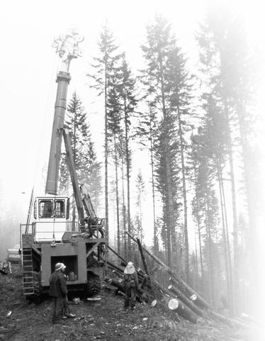
3 PRIMARY TRANSPORT EQUIPMENT Harvesting timber consists of several phases: falling the trees, manufacturing them into logs, and transporting the logs from the stump to a landing or roadside and then to a conversion facility. Many factors influence the exact sequence and details of these phases, but regardless of the details, the basic concept remains the same: harvesting timber consists of cutting trees and transporting them from one location to another. The operations are conducted sequentially, and the output of one phase becomes the input to the subsequent phase. The most common method for classifying harvesting systems is to consider the primary transport phase; that is, from stump to the landing or roadside. Although usually the second phase in sequence, primary transport is discussed first in the handbook because of its importance. The three basic classes of primary transport are ground-based, cable, and aerial. In groundbased harvesting systems, the logs are dragged or carried from the stump to the landing by a machine that travels over the ground. In cable systems, an overhead cable attached to a stationary machine is used to drag or carry the logs; in aerial systems, the logs are lifted above the ground by a machine that derives its lift from the air. This section of the handbook describes the defining features of these three classes of primary transport equipment. The features described here determine the generally accepted operating range of the equipment, but not necessarily the entire operating range. Some makes or models may include unique features used to extend the normal operating range. These unique design Figure 4 A mid-sized skidder, typical of many ground-based operations in the Interior of British Columbia, working on a landing with a dangle-head processor. Figure 5 A mid-sized swing yarder. Figure 6 A heavy-lift helicopter used in coastal areas. 49

4 features, or even special operating techniques, allow equipment to be operated outside of its normal operating range. While the handbook describes typical operating ranges, every situation should be examined on its own merit to determine the risk of using the proposed equipment under the expected site conditions. Common Features of Ground-based Equipment Ground-based equipment travels from the landing or roadside to the stump and returns with a payload of logs. This process requires that roads be located within an acceptable skidding distance of the felling site, and that the site have terrain that is not too steep or broken and soils strong enough to support the machine. Machines travel across the ground to the cutting site Since they simply drive over the ground, ground-based equipment can be less complex than either cable or aerial equipment. And since, by definition, they drive over the growing site, this equipment may affect the growing conditions. Less complex ground-based equipment is typically less costly to own and operate than either cable or aerial systems. Figure 7 A large grapple skidder operating from a landing in the Interior of British Columbia. There is an inherent risk of soil damage from machine traffic. Soil damage typically occurs when the machines travel over the same route several times, exceed the soil bearing strength (see soil bearing strength, following), and turn around at the felling site, landing, or roadside. Design features or operating techniques that reduce the risk of these occurrences are important to consider. For example, the turning action for tracked machines causes one track to skid over the ground which can cause soil disturbance. Some tracked machines have proportional steering between the tracks to reduce or eliminate the skidding effect when turning. Two operating strategies to reduce disturbance from turning are (1) to turn the machine only on debris, or (2) to back the machine from the landing to the felling site, and drive forward on the return trip. The latter strategy is commonly used for forwarders and clambunk skidders. Ground-based machines can drive between the residual stems in a partial cutting prescription. Unlike cable systems, a straight corridor is not required; however, a sufficient number of trees must be cut to allow the machine and its payload to pass without binding or breaking, or damaging residual trees. Crossing streams with ground-based equipment may cause unacceptable disturbance, and must be strictly controlled. Temporary bridge crossings may provide one method for crossing the stream within allowable disturbance limits, and equipment such as forwarders can carry the bridge to the site and place it in position with minimal disturbance. 50 Primary Transport Equipment

5 Soil requires adequate load-bearing strength Because the soil must support the machine and payload weight, inadequate soil strength can result in soil degradation such as compaction or rutting. In general, coarse, welldrained soils are stronger than fine-textured or moist soils. The soil s strength may be enhanced by frozen conditions, or the machine s weight can be distributed over a wider area by using wide tires, wide-track pads, flotation mats, woody debris, or deep snow to prevent damage to the soil. On sites that are highly sensitive to soil compaction and puddling, it is common to schedule harvesting operations when the soil strength is greatest (i.e., under dry or frozen conditions), or to select harvesting systems other than groundbased. Operating in areas with soils with low load-bearing capacity may require different operating techniques such as operating only at certain times of the year, using wide tires, or using particular skidding patterns. These techniques are discussed later in the handbook. Figure 8 Wide tires reduce the ground pressure of this skidder. Operating on soils with low load-bearing capacity will increase the cycle times because the machine may get stuck, its travel speed may be reduced, or its payload may be reduced. Maintenance costs will be increased because of increased wear and tear on the machine. Soil compaction and rutting can result from operating ground-based equipment on soils with low load-bearing capacity, which can lead to soil erosion or reduction in growing site. Suitable ground slope required The ground slope must be within the safe operating range, which varies depending on the type of equipment. Typical maximum favourable slope limits for wheeled skidders are 35%, and tracked machines can work to about 50%. Some specialized tracked machines can operate on slopes up to 60%. The upper limit for loaders working as forwarders is about 25 35%. Occupational safety rules may restrict the range of slopes for ground-based equipment. Check for regulations that may apply in the particular operating area or jurisdiction. Ground-based equipment can become unstable on steep slopes, especially when turning. Small obstacles such as windfalls and stumps that can be negotiated safely on lesser slopes may cause the machine to overturn. When skidding downhill with line skidders on steep slopes, the logs may run ahead into the machine, thus presenting a safety hazard. Common Features of Ground-based Equipment 51
6 Skidders can travel in random patterns on gentle slopes, but require trails to be constructed on steeper slopes. Constructing and deactivating trails increase costs. Cycle times are increased on steep slopes. Bladed skid trails are a potential source of sediment generation. Subsurface flow can be intercepted and concentrated by bladed skid trails, and become a way to transport sediment. Without site rehabilitation, skid trails may not become sufficiently restocked with desirable species. Roads required within skidding distance The typical maximum skidding distance for wheeled equipment is approximately m, although some machines can operate economically up to m. Track-mounted machines are typically economical for shorter distances below 200 m. Distances of 800 m cannot usually be obtained within a single cutblock; instead, they often imply travel through dead ground that is not being harvested. An exception is forwarding from small patches long-distance skidding equipment can be used to centralize the processing and loading in a single location rather than in each of the patches. Figure 9 The relative advantage of different machines changes depending on the skidding distance. The maximum skidding distances are determined by economics, not by physical limitations of the machines. Longer skid distances increase the cycle times and skidding costs, while shorter skidding distances reduce the skidding costs and increase the road density and the road-construction costs. Larger payloads can offset the effect of longer skidding distances because fewer cycles are required to transport the same volume of timber. The relative effect of skidding distance on productivity varies according to the type of equipment, and is a function of travel speed, payload, and hookup and unhook times. Machines with fast hookup times and low payloads (e.g., grapple skidder) are most effective at short skidding distances. Conversely, machines with large payloads and longer loading and unloading times (e.g., line skidder) are more effective at longer distances. In Figure 9 (adapted from Plamondon and Favreau 1994), the productivity functions for grapple and line skidders cross at about 100 m skidding distance. The relative effectiveness of the two machines varies with distance. Short skidding distances increase the road density, which increases the potential for siltation and reduces the net area for restocking. Longer skidding distances reduce the road density, but can increase the soil compaction on skid trails. Longer skid distances can also increase the amount of soil compaction near the road because of increased traffic. 52 Primary Transport Equipment

7 Favourable travel surface required Ground-based equipment requires that the ground surface be relatively uniform, and free from large, impassable obstacles. For example, large boulders, gullies, or stumps may hamper the machine s mobility. However, broken ground can also enhance the mobility if the ground is interspersed with passable trails. For example, steep ground with benches can be harvested safely, especially if the timber can be felled towards the benches within the machine s reach. Short pitches of steep ground can be traversed safely. Figure 10 A forwarder working under nearly ideal conditions: the terrain is uniform, with no obstacles, and has only a slight adverse grade. Obstacles increase the cycle times and skidding costs, and can become hazards for overturning the machines. Every part of the cutblock must be close enough to a safe travel corridor for the machine to reach the logs. The potential for soil disturbance, erosion, or mass wasting caused by channelling water increases near gullies. Downhill skidding preferred Ground-based equipment can usually skid downhill better than uphill; therefore, the truck road should be located in the lower portion of the cutblock. Short, steep pitches or sustained, gentle adverse slopes are acceptable. The amount of adverse grade that is acceptable depends on the type of machine. Skidding on adverse slopes reduces travel speed and decreases productivity, and may require specialized equipment. The average skidding distance for a cutblock increases for a given road spacing because most of the skidding is from one side of the road only, instead of both sides as it would be for both adverse and favourable skidding. Spinning wheels or tracks on adverse skids can cause soil damage that can lead to increased siltation. Distinguishing Features of Ground-based Equipment Three major features distinguish the various ground-based machines from one another: the machine type or method for transporting the trees or logs, the tractive system, and the machine size. An additional characteristic of skidders is the method used for holding the logs. Distinguishing Features of Ground-based Equipment 53


8 Figure 11 The skidder pushes the logs into a pile to keep the landing clear. Figure 12 A tracked skidder with a swing-boom grapple. The track frame is extended towards the rear of the machine to improve the balance. Log transport method Ground-based machines use several different methods for holding and transporting the logs: the method used defines the type of machine. The most common ground-based equipment is the skidder, which drags the logs behind itself while holding one end of the logs off the ground. The clambunk, a variation of the skidder, holds the logs in an inverted grapple. A second type is the forwarder, which carries the logs completely off the ground. A third type is the loader-forwarder, a loader that picks up the logs to swing or carry them a short distance. When log loaders are used from the haul road without travelling into the cutblock, they are usually called cherry pickers. Horse logging or small-scale equipment such as chainsaw-powered winches or allterrain vehicles are generally limited to smaller, niche operations. Each of these types will be discussed in detail. Skidder Skidders are used for a wide range of applications, from the smallest operations to large, fully mechanized systems various sizes suit different purposes. Skidders can be classified by their tractive system (rubber tires or tracks) and their method for holding the logs (chokers, grapple, or swing-boom grapple), as discussed later in detail. In a typical work cycle, skidders travel from the landing or roadside to the felling site, turn around to hook the logs, and drag the logs to the destination. Depending on what other equipment is working in the system, the skidder may push the logs into larger piles to keep the landing area clear. Log breakage may result from rough handling with the skidder. The weight of the logs is usually distributed unevenly between the front and rear of the machine, with the rear usually carrying a larger portion of the load. This results in increased ground pressure on the rear of the machine and adversely affects the machine s ability to skid uphill. Some skidders are specially designed to distribute the weight more evenly, thus improving their adverse skidding and ground pressure characteristics. Many contractors choose skidders because they are less expensive to own and operate, are versatile, and are well understood. Skidders are best suited to short to medium skidding distances. At longer distances (over m), skidders become less economical to operate.the economically 54 Primary Transport Equipment


9 operable distance depends on travel speed and turn volumes machines with faster cycle times or larger turn volumes can operate economically at longer distances. Turning the machine around at the felling site on a steep sideslope is one of the most hazardous phases of the work cycle because skidders are unstable when positioned crossways on the slope. One technique to address this problem is to construct a trail to the top of the hill for returning to the work site. This allows the skidders to travel straight downhill over the steep ground. On broken ground, the skidders can turn on the benches and back up the hill for a short distance. Figure 13 A rubber-tired grapple skidder about to hook up a turn before starting to the landing. Because of their low payloads, skidders require many trips over the same ground to harvest all the volume. This travel can lead to soil compaction on sensitive sites. Skidders may require bladed skid trails on steep ground, which can result in the loss of productive growing sites. In addition, skid trails may require rehabilitation after harvesting to restore the original ground slope and natural drainage patterns to reclaim the growing site and reduce the potential for soil erosion. On steep ground, the tracks caused by dragging the logs on the ground can become pathways for water to accumulate and flow. Clambunk A clambunk resembles a large skidder with a log loader and grapple mounted on the rear of the machine. The grapple, which is mounted with the opening facing upwards, opens like a clamshell, thus deriving the machine s name. In a typical work cycle, the clambunk travels in reverse from the roadside to the backline, eliminating the need to turn the machine around at either end of its cycle. Operators face the rear of the machine, looking over their shoulder when the machine travels forwards; the low travel speed makes this practical. The butt ends of the logs are lifted into the grapple with the loader; when all the nearby logs have been loaded, the grapple is closed to secure the load. The machine travels forward to the next loading site, and the process is repeated until the grapple is full. Then the clambunk travels to the roadside to unload the logs, either by opening the grapple and driving out from under the load, or by using the log loader. The former technique is faster, but leaves the logs somewhat tangled for subsequent processing. Figure 14 A clambunk skidder. Note the large, inverted grapple ( clambunk ) and the tracks over the tires. Distinguishing Features of Ground-based Equipment 55

10 Clambunks usually have more axles than conventional skidders, and have a tire-andtrack tractive system, so they can work on weaker soils. Figure 15 A clambunk skidder operating on flat ground on the Interior Plateau. Clambunks are large, slow-moving, and highly productive machines with large payloads and high ownership costs. Therefore, to minimize production costs, they are best suited to working with other high-production equipment such as feller-bunchers and mechanical processors in a highly mechanized, roadside system. The high capital cost means that the operating season must be extended as long as possible to help amortize the ownership costs. Clambunks usually build their payloads from several smaller piles over a relatively long distance during which time they must travel more-or-less straight ahead. They require a fairly deep cutblock to use their full payload capacity. With their long loading times, clambunks are better suited for long skidding distances than for short distances. Backline distances of m are reasonable for clambunk skidding, and distances up to 800 m are feasible, especially if the clambunk is paired with a conventional skidder. The skidder works on the front portion of the cutblock, while the clambunk works on the back end. However, too deep a cutblock can be detrimental if the volume of timber becomes so large that it cannot all be piled easily at roadside. One method to deal with large volume is to skid, process, and load a portion of the timber at a time. This technique requires extra travel for the processing and loading equipment, and more coordination between phases. Alternatively, the clambunk can offload the logs with its loader to pile them higher, or a secondary loader can be used. Because the ground bearing area is larger for clambunks than for skidders, the clambunks may be able to operate on softer ground without causing excessive soil disturbance. Therefore, the operating season for clambunks can be longer than for skidders (e.g., can operate when the soil moisture content may be too high for conventional skidders). Clambunks do very little turning compared with conventional skidders, so they are not limited by the same slope constraints. Furthermore, the weight of the load bears down on the machines which helps them from overturning. Clambunks can be operated safely on slopes up to 60%. Clambunks can operate on weaker soils than skidders because of their track and wheel systems (see Tractive systems section). Furthermore, their loading sequence requires them to travel over a portion of the skidding distance with only a partial payload. With proper planning and supervision, the partly loaded portion of the cycle could coincide with the weaker soils, thus reducing the ground impact. Their large size and limited maneuverability make clambunks poorly suited to partial cutting operations. Their wide trails compared with conventional skidders make it 56 Primary Transport Equipment
 systems with equipment such as feller-processors and shortwood loaders and trucks.")


11 harder to protect advance regeneration. Forwarder Forwarders are highly specialized machines used in cut-to-length (CTL) systems with equipment such as feller-processors and shortwood loaders and trucks. A key feature of the CTL system is the work done by the feller-processor; it fells and delimbs the trees, cuts the stems into lengths up to 8 m long, and sorts and piles the logs for the forwarder. As the fellerprocessor works, it creates a debris mat from limbs and tops to distribute the weight of the machinery. After the feller-processor cuts the logs, the forwarder travels over the same debris mat to retrieve the logs. See the Operating Techniques section later in the handbook for additional information about the CTL system. Forwarders are built on articulated chassis with two, three, or four axles and large rubber tires. On forwarders with two rear axles, the rear tires are usually equipped with tracks over the tires; the front axles may or may not have tracks. The rear of the forwarder consists of bunks to hold logs, and a log loader mounted behind the cab. The logs are loaded onto the forwarder using its log loader, and then carried to the roadside where they are unloaded. For sorting logs, forwarders can pick individual logs from the piles created by the feller-processor to produce loads of a single type. Once a homogenous load has been moved to the roadside, it can be unloaded into its own area with little additional effort. Different sorts can also be kept separate in the machine s bunk if required. Forwarders travel equally well forward or backward, and the operator s seat is reversible and comfortable for travelling in either direction. Depending on the layout of the Figure 16 A four-axle forwarder. Note that neither the front nor rear axles have tracks over the tires; such equipment is optional, although commonly used. Figure 17 A three-axle forwarder. Note the larger tire on the single front axle. Figure 18 A two-axle forwarder. This configuration is uncommon in British Columbia. Distinguishing Features of Ground-based Equipment 57


12 particular cutblock, the forwarder may travel backward from the roadside to the felling site so that the machine is not required to turn at either end of the cycle. Forwarders can travel quite quickly over bladed trails, especially when empty. They travel more slowly over the debris mat trails, and even more slowly when loaded. Figure 19 A forwarder unloading the logs at roadside. Sawlogs and pulp logs are piled separately. Figure 20 The large load raises the centre of gravity which may cause instability. Economics are an important consideration in the decision to use a CTL system because they are typically more expensive in the stump-to-truck phase than other ground-based systems. The equipment is generally more expensive and less productive than other mechanical systems. However, the stump-to-truck costs should not be considered in isolation of benefits that may accrue to other phases. Some of these benefits include reduced soil disturbance, lengthened operating season, more stable work force, increased fibre recovery from the stand, less breakage, improved log quality, cleaner logs, better sorting, better ability to harvest short trees, and more suitability to partial cuts. The true worth of the CTL system can be determined only by accounting for all costs and benefits for the particular company and location. For additional information about CTL, see the discussion about Combined Systems in the Operating Techniques section later in the handbook. Forwarders are less efficient at short skidding distances than at medium to long distances because of their comparatively long loading and unloading times. Also, short distances may provide less opportunity to make complete loads of a single sort. Forwarders can travel up adverse pitches that could stop a conventional wheeled skidder. Forwarders operate within fully mechanized harvesting systems in which all workers are enclosed in protective cabs; therefore, the safety hazard is low compared to non-mechanized systems. Furthermore, forwarders travel slowly compared with skidders, which further decreases the safety hazard. However, the forwarder payload is carried high on the machine as compared with skidders or clambunks which raises the centre of gravity and introduces some instability. The travel routes for the forwarders should be straight down slopes to eliminate the possibility of becoming turned crossslope and tipping over. 58 Primary Transport Equipment

13 By travelling on a debris mat, rutting and compaction is limited to the forwarder trails. Under some conditions (e.g., soft ground or large amounts of traffic), the debris mat may become beaten into the ground, making it difficult to establish regeneration. Rehabilitating the trails may be required. With at-the-stump processing, all the limbs and tops remain on the cutblock, which eliminates roadside accumulations and may benefit nutrient recycling on some sites. One of the benefits of CTL systems is the ease with which the equipment can maneuver between the residual trees in a partial cutting prescription. The logs are cut short, so winding travel routes can be used to avoid damaging the residual trees. Operating successfully in a partial cut depends on the residual tree spacing and the machine size. Loader-forwarder The loader-forwarder, commonly called hoe-chucker, is a log loader used to move logs from the stump to the roadside. Most loader-forwarders are hydraulic loaders modified with high-clearance undercarriages, although line loaders can be used as loader-forwarders. Starting from the cutblock backline, the loader-forwarder moves the logs closer to the road one step at a time by the length of its reach. The number of logs in the pile increases with each successive pass, until every log from the cutblock is piled at the roadside. Depending on the timber type, falling system, and processing system, the loaderforwarder may travel parallel to or perpendicular to the road. Regardless of the pattern chosen, the objective is to minimize the number of times the machine travels over each section of ground to minimize soil disturbance and operating cost. Loader-forwarders can be outfitted with tongs for hooking logs beyond the reach of the grapple. When used with a free-spooling winch and operated by an experienced worker, the tongs can be cast up to 100 m, thus covering a substantial area. This system requires a second worker to hook the logs, and close communication between the two workers to ensure safe operations. Figure 21 A loader-forwarder working in a secondgrowth forest on Vancouver Island. The loader-forwarder is the most economical method of harvesting for gentle terrain in coastal conditions; for many operations, it has replaced the grapple yarder as the preferred harvesting system. The labour costs are low because only one worker is required. However, loader-forwarders must handle each log several times before it reaches the roadside, so the maximum distance for moving logs is short compared with other ground-based equipment. Four or five passes with the machine is considered normal, although examples of up to 10 passes are not uncommon for special circumstances. The distance covered with each pass varies with the machine size, but for large coastal equipment, m per pass is common, which equates to a maximum backline distance of about 150 m. Distinguishing Features of Ground-based Equipment 59

14 To improve their productivity, loader-forwarders are used to great advantage with other machines such as grapple yarders and skidders, especially when working around sensitive zones. The loader-forwarders can travel close to the sensitive zones, extract the logs without encroaching on the protected areas, and place the logs in a more advantageous position for the primary equipment to reach. This technique can be more economical for the overall system. Excavators are highly mobile machines that can traverse a wide variety of terrain. The grapple can be used to stabilize the machine on steep ground to minimize the danger of overturning. Since there is only one worker with the machine, the hazard to other personnel is low. Sideslope and soil type govern the limit to safe operation. The maximum sideslope for using a loader-forwarder is about 25 35%, especially if the sideslope is uniform. For more broken terrain, loader-forwarders can operate on steeper terrain, provided that they can travel and work safely on an acceptable route through the steep ground. Loader-forwarders cannot work safely on thin soils overlaying bedrock because of the danger of sliding. However, the hazard can be reduced by using flotation mats. The sliding hazard is aggravated with snowfall. Figure 22 The loader-forwarder is often the preferred machine on gentle terrain in coastal operations. The travel routes must be planned carefully to avoid soft soils and excessively steep ground, or special precautions must be used to avoid disturbing the soil. Proper route planning is a key factor in minimizing environmental impact. The soil must be strong and dry enough to support the machine, although building mats with debris or using manufactured mats allows the machine to be used on softer ground. Soil disturbance is more likely to occur where the machine changes its travel direction, so turning in the more sensitive areas should be avoided. The logs harvested by a loader-forwarder are actually carried from the stump to the roadside so the logs themselves do not cause any soil disturbance. Loader-forwarders can work in partial cutting prescriptions to remove timber without causing significant damage to the residual trees. Loader-forwarders can work safely around riparian zones without affecting the actual watercourse because these machines can reach into the stand to retrieve logs while remaining outside of the machine-free zone. Furthermore, they can move with minimal soil disturbance if the travel route avoids turns within the sensitive zone. Lastly, they can grasp standing trees that are being felled to help with directional control and avoid affecting the protected areas. These features make excavators ideally suited to working near riparian areas to harvest the timber without affecting water quality. 60 Primary Transport Equipment

15 Cherry picker A cherry picker is a loader used for loading right-of-way logs directly onto log trucks without another machine having first transported the logs to the roadside. Rightof-way logs usually have the lowest production costs of all harvesting methods, and forest companies often maximize the amount of volume produced by this method. Figure 23 A coastal line loader. The boom extension ( snorkel ) on this machine is quite long identifying it as a cherry picker suited to working away from confined spaces such as near a yarder. Cherry pickers can be line loaders or hydraulic loaders. Line loaders can typically reach a wider area than hydraulic loaders because they can throw or cast the grapple beyond their normal range. The grapple can be cast m downhill, but cannot be cast on the uphill side of the road. Extending the boom of a line loader with a snorkel is a common method for increasing the amount of accessible timber. Super snorkels are specialized line loaders with boom extension up to 35 m long. The total distance from the centreline of the loader to the tip of the snorkel is about 45 m, so a significant area can be harvested without a machine actually travelling off the road surface. The extra-long snorkel, which reduces the mobility of the machine, must be removed for transport between work sites. Super snorkels are seldom used for loading trucks because the snorkel can reach over the log truck cab, which presents an unacceptable safety hazard. Figure 24 The boom on this super snorkel has three 12-m extensions. The machine can retrieve logs about 50 m from the road without additional support equipment. Since cherry pickers work directly from the road surface, their impact is limited to the road itself. Drainage structures such as ditches and culverts must remain functional during and after operations. Since super snorkels are large, heavy machines, the road and drainage structures must be built wide and firm enough to support the weight of the machine without failing. Horse Horses are quiet, can maneuver easily in partial cuts, and have an aesthetic appeal to the public that gives them a special advantage in certain situations. They work well for selection and thinning operations, and near urban areas. However, they have Distinguishing Features of Ground-based Equipment 61

16 limited productivity and can work only on gentle terrain. Furthermore, as living creatures, they require a special level of tending and handling. Figure 25 Skidding with horses in a partial cut. Horses are limited to gentle terrain with favourable grades up to 25%. On steeper ground, the logs can overrun the horses. The ground must be dry or frozen, and heavy underbrush or slash can impede their travel. Snow can improve skidding conditions by reducing the friction between the log and the ground. All branch stubs must be trimmed so they do not poke into the ground, making the logs difficult to move. Horses can maneuver easily through partial cuts, and their low travel speed can help to minimize the scarring to residual trees. The average skidding distance should be kept under 100 m, with long corners up to 300 m. Horses can also be used for forwarding, with the addition of a wagon or sleigh, and economic distances can be increased up to 500 m. The travel corridor must be cleared of logs or debris ahead of time because horses cannot clear their own trail. The logs are usually piled manually at roadside in preparation for self-loading trucks. The main environmental advantage of horse logging, in addition to working well in thinning or selection cutting, is its quiet operation and visual appeal. The soil disturbance caused by horses is limited to the travel corridors, but can be severe on the skid trails because the horses ground pressure is relatively high. Soil disturbance can also be caused by the ends of the logs gouging the soil; various accessories are available to lift the logs and reduce this damage. Small-scale equipment Various small winches, arches, all-terrain-vehicles (ATVs), and tractors, as well as cable systems such as chainsaw-powered winches, are available for small-scale operations. None of these systems is widely used in British Columbia. In Eastern Canada, where small woodlots constitute a higher proportion of the total harvested volume, these systems have more acceptance. Small-scale equipment has low capital requirements compared with more conventional equipment. However, it is less productive, and generally limited to specialized operations. These systems are usually low-speed, low-impact machines that can be used in and around sensitive areas. These machines are less likely to be used by a large company, and more likely to be used by an individual operator who may not have established management and control 62 Primary Transport Equipment


17 procedures. Environmental awareness could be lacking. On the other hand, the individual may be more aware of environmental protection. Self-discipline and environmental awareness are as important with smallscale equipment as with conventional equipment. Figure 26 A small, powered tractor which is loaded by hand. This system makes it possible for one worker to move several logs at a time. Tractive system The tractive system defines how the machine transfers the engine power to the ground to propel it forward. The four systems are rubber tires, tracks, flex tracks, and tracks over tires. These different systems affect the machine s travel speed, operating costs, stability, and soil disturbance levels. Rubber tires Rubber tires provide the highest travel speeds, although they also require the best ground conditions for travelling comfortably. In general, wheeled machines are suitable for slopes up to about 35%, although steeper slopes can be crossed for short distances or by using extra care. Above 35%, machine stability decreases, traction becomes a limiting factor, and cycle times and costs increase. The high travel speed for wheeled machines makes them suitable for longer skidding distances, especially if combined with a large payload. Typical maximum skidding distances for wheeled machines are up to 300 m, but distances up to 800 m may be feasible for machines with large payloads. Wheeled machines are poorly suited to adverse grades. They are also adversely affected by deep snow, and may require a helper machine to build trails for travelling. Figure 27 Tire tracks are used to increase the contact area of the tire and reduce ground pressure. Wheeled machines often require bladed trails for operating on slopes over 35%. Bladed trails generate siltation and occupy potential growing site. Wheeled machines typically cause more soil compaction than tracked machines. They are especially susceptible to causing damage when the soil moisture content is high. Chains or tracked devices can be fitted to rubber tires to improve traction and reduce soil disturbance. Wide tires or dual tires increase the footprint of the machine and reduce the ground pressure, but they also make the machine more difficult to maneuver between residual stems, advance regeneration, or windfall. The operating costs are also increased with these modifications. Distinguishing Features of Ground-based Equipment 63

18 Figure 28 A small tractor with a high drive track system. It provides better machine balance and elevates the drive gears above the dirt and debris. Tracks Tracked machines are typically slower than wheeled machines, but they have increased stability, traction, and skidding power. Tracked machines turn by varying the relative speed between the two tracks. To vary the speed, either one track is disengaged from the drive system (i.e., with a clutch), or the distribution of power is altered between the tracks (i.e., with planetary or hydrostatic drive system). The latter method, although more complex mechanically, maintains power to both tracks at all times. Such design can result in less soil disturbance while turning. Tracked machines can typically be used on slopes up to 50%, although steeper ground can be negotiated safely for short pitches by using extreme caution. Tracked machines can skid up adverse slopes better than rubber-tired machines. Their slower travel speed makes tracked machines more suited to shorter skidding distances, typically under 200 m. At longer distances, working with a wheeled machine is effective. The tracked machine does the initial skidding, typically from steep slopes to a staging area; the faster machine then completes the skidding to the landing. Tracked machines do not work well on rock because of the danger of sliding, but they can work in deep snow that may stop wheeled machines from working. The owning and operating costs for tracked undercarriages are higher than for wheeled machines. Tracks are usually available in several widths. Narrow tracks increase the ground pressure, while wide tracks reduce the ground pressure of the machine. Wide tracks also make the machine less maneuverable, more expensive to purchase and maintain, and more prone to sliding in slippery conditions. When operated appropriately, tracked machines have minimal soil impact; however, they can significantly damage soil if operated improperly. For example, operating tracked machines on sensitive soils during wet conditions can cause significant soil compaction and/or puddling. During turning, tracked machines can cause significant soil disturbance where the machines are turned. Paying strict attention to where and how often the machines are turned can have a large impact on the soil disturbance levels. Flex tracks In contrast to conventional, rigid-frame tracked machines, flex-track machines have suspensions that allow the track to conform to the shape of the ground. This feature allows the machine to maintain ground contact over the full length of the track at all times. 64 Primary Transport Equipment

19 On steep ground, flex-track machines are less affected than rigid-frame machines by obstacles such as stumps and windfalls. The flexible suspension allows the machines to walk over the obstacles by conforming to their shape and provides a higher level of stability. In contrast, conventional tracked machines have rigid track-frames that cause them to lose contact with the ground except for a short length of track when they climb over obstacles. Flex-track machines can operate safely on slopes up to 60%. The tracks ability to maintain ground contact can aid flex-track machines on adverse skids. Flex-track machines can also travel faster than conventional tracked machines, thus increasing their productivity and lowering the costs. Higher travel speed also makes them more suitable for longer skid distances. However, these machines are generally perceived to have higher operating and maintenance costs than conventional tracked machines, and are justified for only a narrow range of sites. For example, flex-track machines may be considered for sites too steep or sensitive for conventional ground equipment, yet not steep or sensitive enough to justify cable systems. When used carefully, flex-track machines can operate on soft ground without causing rutting because they maintain full contact with the ground and cause no pressure points where the ground pressure is increased. The flex-track feature can further reduce soil damage because track spinning and shock loading as the machines travel over obstacles are reduced. However, these machines also travel faster than conventional tracked machines, which can lead to mechanical soil damage if they are operated carelessly on sensitive sites. Figure 29 The flex-track system. The wheels run on the inside of the track and are suspended independently, allowing the tracks to conform more closely to the ground profile than rigid-frame tracked machines. Figure 30 Comparison of rigidframe and flex-track suspensions crossing an obstacle. The weight on the rigidframe suspension is concentrated at two points, but is spread out for the flex-track suspension. Furthermore, the rigid-frame suspension exerts a high-impact loading at the front of the track when it pivots over the obstacle. Distinguishing Features of Ground-based Equipment 65

20 Figure 31 Tracks increase the contact area of the wheels and decrease ground pressure. This tractive system is typical for forwarders and clambunks. Tires with tracks A common method for reducing the ground pressure and improving traction of forwarders or clambunks is to mount a set of tracks over double-bogie tires. Tire-and-track machines travel quite slowly. However, they typically have large payloads that make them suitable for longer skidding distances. The slow travel speed minimizes the amount of mechanical damage to the soil. The lower ground pressure compared with rubber-tired machines means that they can operate successfully on weaker soils without causing as much soil compaction. This also has the effect of extending the operating season, which can improve the operating economics. Method used by skidders to hold logs Skidders can be equipped with one of three different ways of holding the logs: chokers, grapple, or swing-boom grapple. These different methods affect the suitability of the skidder to different tasks. Chokers Chokers are wire ropes for hooking the logs to the skidder. Skidders that use chokers are often called line or cable skidders. Chokers can be pulled from the skidder for up to 25 m to hook scattered logs; the skidder does not have to travel to the logs as it would with a grapple. A single choker can be used for a single log or several logs in a bunch, and several chokers are normally used at a time. Line skidders are less expensive to purchase than grapple skidders, but their productivity is lower over short skidding distances because the hookup and unhook times are much longer. However, chokers are more suitable for long skidding distances, with scattered logs, or for situations where the skidder cannot travel right up to the log. For example, a line skidder may be used to harvest logs from a gully by stopping away from the actual hookup site and winching the logs out of the gully. The skidder operators must climb on and off the skidder frequently to hook and unhook the chokers, which exposes them to slip-and-fall accidents, a common injury to skidder operators. Chokers are more labour-intensive than grapples. When skidding downhill on steep slopes, the logs may slide forward and strike the skidder. Chokers are commonly used for skidders involved in cleanup operations, such as after blowdown. Logs can be hooked and unhooked individually, which facilitates sorting. 66 Primary Transport Equipment


21 Chokers can be used to pull logs from riparian zones without the machine encroaching on the protected zone. For partial cutting prescriptions on sites where feller-bunchers cannot be used, chokers can retrieve the logs from among the residual trees. Chokers allow the machines to stay on designated trails, and avoid soil disturbance between the trails. If the skidder encounters a section of soft ground, the winch can be disengaged, and the skidder moved ahead to better ground. The winch can be engaged, and the logs pulled into the machine. This technique, which can decrease soil disturbance, is especially valuable on adverse skids. Grapple A grapple is a tong-like mechanism for grasping logs; its primary benefit is to reduce the hookup and unhook times. To hook the logs with the grapple, the skidder must drive to within a few metres of the logs and be aligned with their ends. Grapple skidders work best with feller-bunchers because making a turn with individual logs is very time-consuming. Figure 32 Chokers require the operator to dismount from the machine to hook the logs. Figure 33 Hookup with a grapple is controlled from the machine s cab. This skidder uses a parallelogram mounting that allows for fore-and-aft movement of the grapple. Grapple skidders are more expensive to purchase than line skidders, but they can also be more productive. More important, however, is the requirement to use the grapple skidder with a feller-buncher. This combination increases the total capital requirements of the whole logging system and changes the business environment: switching from a line skidder to a grapple skidder requires production levels high enough to justify the capital expense of the additional equipment. Grapple skidders are better suited to highproduction operations; line skidders are better suited to smaller operations. Since the skidder must be aligned with the bunches to hook onto them, using grapple skidders can increase the amount of maneuvering, and the machine can roll over on steep slopes if the operator is not careful. On a positive note, the operator remains enclosed in a protective cab, which reduces the risk of injury. Distinguishing Features of Ground-based Equipment 67

22 Figure 34 This swing-boom grapple facilitates reaching logs on either side of the skidder. Note the use of tire chains to improve traction. Because grapple skidders must be immediately adjacent to the logs to hook onto them, they are poorly suited to working around sensitive riparian zones. Some grapple skidders are equipped with an auxiliary winch to use with chokers in such situations. More maneuvering at the hookup site compared with line skidders may increase soil disturbance and increase damage to advance regeneration. Swing-boom grapple A swing-boom grapple is like a log-loader mounted on the rear of the skidder. While similar to a conventional grapple, it can reach logs farther away from the machine, especially those that lie to one side of the machine. The reach is limited to about 3 m. Swing-boom grapples are smaller than conventional grapples, so their payload is reduced, which is a disincentive to use them exclusively. On steep slopes, the swing-boom grapple can reach log bunches that would normally require maneuvering the machine. This feature can reduce the cycle times as well as improve the safety factor. Conversely, the weight distribution between the axles is adversely affected compared with conventional grapple skidders, which reduces the pulling ability of the skidders. At the landing, the logs can be piled using the swing capability of the grapple without the skidder driving onto the log pile. This technique can reduce log damage. The swing-boom grapple requires less turning than conventional grapples to align with the logs, which can reduce soil disturbance. Size One of the most obvious distinguishing features between different machines is their size, which can make them suitable for different purposes. It is important to match the machine size to the expected timber size, turn volume, and annual production to minimize costs. Larger machines can handle larger timber without being overloaded and with a reduced risk of mechanical failures. If insufficient timber is available to fully load a large machine, production costs will increase. Large machines generally cost more to own and operate than small machines, both in absolute terms and hourly costs. However, they can be more productive so their unit costs can be lower. But to keep the unit costs lower, the total annual production must be higher. 68 Primary Transport Equipment


23 This requirement makes the cost of production delays more critical for larger machines than for smaller machines; owners prefer to keep the big machines doing what they do best harvesting timber. This preference can influence the techniques for harvesting near sensitive zones where special care may be required and production may be delayed. A strategy to reduce the effect of production delays is to use a secondary machine for special areas. This strategy allows the primary machine to continue working at full capacity, but also requires that the contractor and/or licensee be able to afford a second machine for special projects. Smaller machines can work better between the residual trees in a partial cutting prescription. Large machines generally have more power than small machines, and may be better suited to working on random skid patterns on steeper ground. Where skid trails are required, large machines require larger trails to be constructed, which can increase the amount of site disturbance. Large machines are usually better able to travel through deep snow without assistance. Figure 35 A mid-size skidder with a single-action grapple mounting. This mounting has a limited range of movement compared with swingboom grapples or parallelogram grapple mounts. Figure 36 This conventional tractor is one of the smaller machines used for skidding. It was used in an individualtree-selection harvesting system in second growth on Vancouver Island. A barrel used to protect the trees from scarring damage is visible on the left. Distinguishing Features of Ground-based Equipment 69

24 Common Features of Cable Equipment Cable logging machines ( yarders ) are positioned and anchored on the landing or truck road, and use one or more cables to drag the logs from the felling site to the landing or roadside. Cable systems require that a path be cleared in a straight line from the yarder to the backline anchor. Furthermore, the path must have a ground profile to accommodate the load path as it supports the payload. Figure 37 Adequate deflection and clearance are required for successful cable operations from both operational and environmental perspectives. Figure 38 A mid-sized swing yarder capable of grapple or skyline yarding. Its small size allows for easy transport between work sites. Cable should hang free and clear of the ground Several factors determine the payload capacity of a cable system: the safe working tension for the cable, the anchor strength, and the cable geometry as determined by the ground profile and engineering. The distance between the chord and the cable, or deflection, is important in determining the payload the greater the deflection, the greater the potential payload. Since cables hang in an arc, concave ground profiles provide the maximum payload. The critical point for maximum payload can occur at any point within the span, but is usually specified as if it occurs at midspan. For short distances and light payloads, 6% deflection may be adequate, but for larger payloads, up to 15% deflection may be required (deflection is measured as a percentage of the horizontal span). In addition to the cable deflection, the ground profile must also provide adequate clearance for the carriage, chokers, grapple, and part of the logs lengths as determined by the obstacle-clearance requirements. This distance can be 20 m or more below the cable for fully suspended payloads. Adequate deflection and clearance allow for the front ends of the logs to be lifted clear of the ground as they are yarded. The term deflection is often used to describe the general shape of a ground profile; in this context, it refers to the combination of deflection and clearance. While not strictly correct, it provides a good measure for the suitability of the profile for successful cable operations. Ultimately, the user must include clearance in the analysis. When used with the appropriate yarding system, backspars, intermediate supports, or both can increase ground clearance in areas of insufficient deflection. 70 Primary Transport Equipment

25 Inadequate deflection and clearance may limit the maximum yarding distance to less than the machine s capacity. Payload will be reduced below optimal, reducing productivity and increasing costs. Without adequate clearance, the cables could drag on the ground and the logs may cause soil disturbance or become stuck behind obstacles. Proper engineering before falling commences ensures that deflection and clearance will be adequate to harvest the timber from all parts of the cutblock. Productivity is reduced when logs become stuck or equipment is broken because of poor deflection. The risk of debris being tossed through the air and striking a worker or of cables breaking and causing injury increases with poor deflection. Too much deflection can increase cycle times for skylines because of the increased time required to lower the chokers from the carriage to the ground and then back to the carriage. Ground disturbance usually occurs in areas of poor deflection where the leading end of the log cannot be lifted clear of the ground. Full and partial suspension are discussed in more detail in the Operating Techniques section of this handbook. The cable must lie in a straight line from the yarder to the tailhold. Therefore, a straight corridor must be cut through the residual trees when a cable system is used for a partial cutting prescription. Traffic over the ground is reduced Machine traffic on the ground is virtually eliminated with cable systems compared with groundbased systems (mobile backspars are sometimes used). Logs can be lifted clear of the ground with some cable systems, although partial suspension is more common. A significant amount of soil disturbance can occur near the landing, where the logs usually touch the ground. The ground disturbance caused by the logs can become a pathway for surface water to travel and cause erosion. See the Machine mobility section for a discussion of the differences between towers, swing yarders, and yarding direction relating to surfacewater flow. Figure 39 A skyline corridor cut through a secondgrowth stand on Vancouver Island. The corridor is approximately 4 m wide, and cut in a straight line from the yarder to the backspar. It allows the skyline cable to hang free and clear, without any interference from the ground or the residual trees. The labour and equipment requirements for cable yarding often make it more expensive to own and operate than ground-based systems. Depending on the capability of the specific yarder, road construction costs can be reduced by increasing the yarding distances. Common Features of Cable Equipment 71

26 The machinery does not usually leave the truck road, which reduces the risk of soil damage and its subsequent effect on water quality. With the proper setup, deflection, and operation, trees can be lifted out of gullies or over streams without operating any equipment near the stream channel. Logs can be lifted over existing plantations or other sensitive zones without having to construct roads or skid trails through the protected zones. However, full suspension does not necessarily ensure zero impact debris may fall from the logs or the logs may knock into saplings as they swing from side to side. Backspar trails may be required for grapple yarding; their locations must be planned carefully to minimize site disturbance. Figure 40 A highlead tower operating from a landing. Three guylines hold the tower in position. The yarder and cable are anchored when operating The yarder is anchored to the ground at one end of the span and one or more tailholds are anchored at the other end. The anchors must be strong enough to support the tower, cable, and payload. Stumps are typically used for anchors, but in some situations, stumps are either unavailable or inadequate. In these situations, fabricated anchors such as rock bolts or deadmen will be required. With grapple yarders, auxiliary machines such as excavators or crawler tractors are often used as mobile backspars. Anchoring the tower at each setup requires a certain amount of time, the cost of which must be amortized over the volume to be harvested from that setup. Furthermore, the tailhold must be moved continually from one location to another during yarding to cover the cutblock. In this respect, cable yarding is different from either ground-based or aerial systems because a higher proportion of the total time is spent in setup activities for which there is no production. The costs for this non-productive time must be amortized over the volume harvested at setup, making the cost for cable yarding particularly sensitive to the volume of timber per unit area. In partial cuts, less timber is removed and more setups are required, thus increasing the harvesting costs. Some cable machines are designed for ease of mobility, with minimal setup and moving time, while others require a significant amount of setup time. For example, a longdistance skyline yarder may require several days for each setup, while a small, mobile yarder may be ready for operations within a few hours of arriving at the work site. Pulling a guyline anchor or tailhold out of the ground can result in the tower falling over or the main cables being whipped around the work site. Either situation is very dangerous, and all anchors must be checked thoroughly to ensure that they are safe. 72 Primary Transport Equipment
27 The stumps remaining in a plantation may be too decayed to use as anchors. If fabricated anchors are required, holes may be excavated to bury deadman anchors, which could destroy some existing regeneration. Alternatively, a machine such as an excavator or tractor may be parked in the plantation to use as an anchor. Roads required within yarding distance The maximum yarding distance with cable systems is limited by the amount of cable carried by the yarder, and can be reduced to less than the maximum capacity by inadequate deflection and clearance. A typical maximum yarding distance is between 200 and 400 m, although some specialized machines can reach up to 2000 m or more. Careful engineering and layout is required to ensure that all the timber lies within yarding distance. In contrast to ground-based or aerial systems that incur only incremental costs to travel additional distance, timber beyond the reach of the cables is difficult to retrieve. Cable extensions can sometimes be added, or additional road may be required, both of which are expensive solutions. Different cable logging systems have different economical yarding distances, depending on cable speeds and payload. Swing yarders configured for grapple yarding typically retrieve logs one at a time, and are short-distance machines (under 200 m). Configured as skylines, they can operate up to 400 m. Long-distance skyline yarders can operate successfully over distances of 1000 m or more, while highlead machines typically operate in the m range. Longer yarding distances can reduce the road network density, which can reduce the amount of siltation generated from the roads and reduce the amount of productive land occupied by roads. Uphill or downhill yarding is feasible Cable systems can be used for both uphill and downhill yarding, although they often work better uphill. The cables remain in tension at all times with uphill yarding and the logs are always under the operator s control. With downhill yarding, the logs tend to slide ahead and may be uncontrolled. On steep downhill yarding, the logs may slip out of the choker and slide down to the road, perhaps striking the machinery or workers. Proper placement of the yarder on the landing or road is critical to ensure safe working conditions. Log breakage may be reduced in uphill yarding because the logs are always fully controlled. In downhill yarding, the operator has less control of the logs, and breakage is more likely. With uphill yarding, the logs tend to slide over the stumps more easily because of the shape of the stumps and the upward pull of the cable, so hangups and delays are reduced compared with downhill. Swing yarders configured for grapple yarding are an exception they are better suited for downhill yarding because the logs are easier to land and pile in this direction. Also, the operator has improved visibility. Common Features of Cable Equipment 73

28 Figure 41 Moving cables always represent a safety hazard. To avoid accidents when working with cable systems, workers must remain alert and aware of their surroundings at all times. Surface water flows down the depressions left by dragging the logs over the ground. With downhill yarding, especially with tower yarding, the tracks tend to converge, thus the runoff tends to converge. With uphill yarding, the tracks tend to diverge, thus spreading out the runoff. See the Machine mobility section for a discussion of the differences between tower and swing yarders, and how the yarding direction can influence the erosion caused by water flowing in the yarding tracks. Moving cables pose a safety hazard There is an inherent safety hazard of working near moving cables. Workers must be aware of the increased hazards posed by moving cables compared with groundbased systems. The increased hazard also results in a higher classification rating and increased fees for workers insurance coverage. The fire hazard posed by cable friction during hot weather requires the use of an after-work watchman once the fire hazard rating has reached specified levels. Distinguishing Features of Cable Equipment The various yarders can be distinguished from one another by four major features: configuration, degree of mobility, method used to hold the logs, and machine size. Figure 42 A highlead yarder. Figure 43 A running skyline. Highlead and skyline configurations All cable systems share one characteristic: a cable fastened to a drum on a winch is used to pull a payload from one location to another. Beyond that, a wide variety of configurations and complexities is possible, although two basic ways to lift the payload off the ground describe the main differences: highlead and skyline. A highlead system consists of only two cables, and operates much like a clothesline. By comparison, a skyline system uses a carriage running on a cable to lift the logs fully or partially off the ground and transport them to roadside. Skylines have many variations, but the addition of a carriage distinguishes skyline systems from highlead systems. 74 Primary Transport Equipment
29 Single-span skylines can be rigged with backspars to elevate the tailhold, and improve deflection. If the deflection is inadequate, then one or more intermediate supports must be added, thus defining the multi-span skyline. Some yarders can be configured as different cable systems by using different setups, cables, and carriages. Highlead The simplest cable system consists of a yarder with a two-drum winch, one of which holds a heavy cable called the mainline, while the other holds a lighter cable called the haulback. The haulback is fastened to the mainline at the point where the chokers are attached using an apparatus called buttrigging. From the butt-rigging, the haulback is run through two sheaves anchored at the backline and back to the yarder. The butt-rigging is raised by applying tension to one line and braking pressure to the other. Typically, only one end of the logs is lifted from the ground. Highlead is considered the most rudimentary cable system because its equipment requirements are minimal. Any two-drum yarder can be rigged for highlead yarding. Capital costs and training requirements are lowest of any of the cable systems. Highlead yarding is relatively unsophisticated. It can be used when deflection is poor because the system will still work even if the cables contact the ground. This practice can cause excessive soil disturbance and reduced productivity, and should be avoided if possible. By attaching a block that runs on the haulback to the butt-rigging, the highlead system can be converted into a running skyline system to provide additional lifting capacity. Figure 44 A live skyline with motorized slackpulling carriage. Figure 45 A multi-span skyline. Figure 46 A highlead yarder typical of coastal cable systems. Chokers are attached to the buttrigging, visible about halfway up the tower. It is difficult to lift the payload completely off the ground because the lift is provided via braking pressure: the only way to lift the payload is to increase the braking pressure on the haulback. This means that one end of the logs must always drag across the ground. Skyline A wide variety of skyline systems is available, from simple conversions of highlead systems, to purpose-built highly mobile swing yarders, to large skyline Distinguishing Features of Cable Equipment 75


30 Figure 47 A large tower rigged for skyline yarding on northern Vancouver Island. towers. Furthermore, skylines can be rigged in many different ways, depending on the equipment, the workers skill and experience, and the requirements of the site. The common characteristic of all these systems is that a cable provides lift to a carriage by means other than simple braking pressure on the haulback. The carriage must run clear of the ground at all locations along the skyline. The carriage can run on the haulback cable (as in grapple yarders), in which case it is called a running skyline, or it can run on a separate cable. If the skyline can be raised and lowered during yarding, it is called a live skyline or slackline; a skyline that is fixed in position during yarding is known as a standing skyline. Skylines are built in a wide range of sizes, as discussed later in this section. Figure 48 A radio-controlled carriage containing an engine to operate the dropline. A similar carriage is visible on the skyline in Figure 47. The main benefit of skylines is that the logs can be given more lift, thus reducing hangups, providing clearance over sensitive zones, extending the yarding distance, and reducing soil disturbance (assuming that the ground profile provides adequate deflection and clearance). Logs can be either fully or partially suspended, as discussed in the Operating Techniques section. Skyline systems require more highly trained workers than highlead systems, especially if backspars are required. The availability of trained workers may be a concern. The cables carry higher loads than highlead systems, so the workers must be more aware of the hazards of working with cables. More safety items must be checked, and communication between various workers becomes more critical. More planning and engineering are also required. The capital costs are higher because of the more sophisticated machinery and the extra hardware required. Setup costs may be increased because of the system complexity. For very large cutblocks, helicopters may be required to transport crew and equipment from the road to the work sites. Skylines provide capabilities that are unavailable in less sophisticated cable systems. They can be used to carry logs over sensitive zones or plantations with minimal impact. Some skylines can extend over 2000 m to provide access to areas without roads. 76 Primary Transport Equipment

31 Depending on cutblock size, a large volume of timber can flow through skyline landings, which can result in site disturbance around the landing. Skyline systems, with their ability to use slackpulling carriages, can work in partial cutting prescriptions where highlead systems cannot operate. However, not all skyline systems are equally well suited to partial cutting. Cable movement within the corridor, with its potential for damaging residual trees, should be considered for assessing the system s suitability; running skylines have the most cable movement. Residual trees can also be damaged as the logs are pulled into the skyline corridor. Multi-span skyline Multi-span skylines use intermediate supports to circumvent the problem of inadequate deflection on uniform or convex slopes. A jack is suspended from a tree in one or more locations to hold the skyline off the ground, and a special carriage that can pass over the jack is required. Suitable equipment must be used to make multi-span skylines feasible. The yarder must be configured correctly, and the carriage must be capable of passing over a jack. Rigging a multi-span skyline adds more complexity to the system compared with other cable systems, and requires more worker training. The number of workers skilled in multi-span yarding limits the use of these skylines. Companies disagree on the usefulness of multi-span skylines. FERIC found during the interviews that multi-span skylines should either be used wherever possible or avoided at all costs, depending on corporate experience. Productivity was reported as either better or worse than conventional cable systems. Notwithstanding the differing opinions on their suitability and cost-effectiveness, multi-span skylines can be used to reach areas of poor deflection without the need of additional roads. Figure 49 This intermediate support was suspended on a cable between two trees. The carriage is about to pass over the support. Soil disturbance can occur in areas of poor deflection, and multi-span skylines are one method of harvesting these areas with less soil disturbance. Any skyline allows for roads to be located away from sensitive areas multi-span skylines extend this capability into areas where single-span skylines might not reach without additional road construction. Multi-span skylines are well suited to partial cutting prescriptions because the intermediate supports keep the skyline within the corridor. Yarder mobility Although yarders remain more-or-less stationary while working, they can be divided into two classes based on their degree of mobility. Towers are intended for use in one place for an extended period of time, while swing yarders are designed to move relatively quickly between sites. Tower Towers are vertical spar trees that are anchored to fixed locations while yarding. The cutblock is harvested by moving the tailhold from one location to another between Distinguishing Features of Cable Equipment 77


32 Figure 50 Towers are anchored in one location when operating. They require substantial landings to provide space for the logs, loader, and truck. This tower was rigged for skyline yarding using a slackpulling carriage. Figure 51 Lacking the ability to swing, towers must drop the logs in a pile beside the landing. yarding roads. The tower itself is not moved between roads, resulting in an overall fanshaped pattern. Since all the logs are yarded to a single location, landings can become congested. After unhooking and piling a number of logs, the pile can become too high for safe working conditions. The landing must provide sufficient room for the machines to be positioned with safe clearances all around for the on-the-ground workers, and for landing, processing, storing, and loading the logs. Much activity is concentrated in a small area, and safety can be a concern, especially on steep, difficult ground where landing size is usually restricted. An auxiliary machine should work with the yarder to keep the landing clear of logs. In coastal operations, a loader usually works with the yarder, while in the Interior, a skidder is often used to forward the logs to another landing. In either case, costs are higher because the productivity of the second machine is governed by the yarder productivity even though it can produce more. Two techniques to help manage the costs of the auxiliary machine are to operate two towers close together, servicing both with a single loader, or to use the loader for primary transport ( cherry-picking ) during its idle times. The ability to work in simultaneously from two landings depends highly on good planning and the site and terrain conditions. In small cutblocks all the timber can possibly be piled in one spot and an auxiliary machine may not be required. The crew size for tower yarders is typically larger than for swing yarders, because chokers are used almost exclusively, and moving the tower and tailhold is a laborious process. Crews of five to seven workers are typical for large highlead towers, although low-production systems require as few as two workers. Towers are typically taller than swing yarders, so they have improved deflection for any given location, which can result in less soil disturbance over the entire cutblock. However, the tracks left by dragging the logs over the ground are concentrated around the landing which can cause high levels of soil disturbance in specific areas. For uphill yarding, any surface drainage flowing in the tracks left by the logs will be 78 Primary Transport Equipment

33 dispersed; however, the reverse is true for downhill yarding, and the water will be concentrated at the landing. This can cause soil erosion if the water is left uncontrolled at the landing. Proper control involves adequate ditching and regular maintenance. Landings located near gullies can cause problems. On one hand, material must not enter the gully because of water quality and slope stability concerns. On the other hand, a landing location near the gully can improve deflection and provide lift to the logs. Alternative landing locations and harvesting systems must be examined thoroughly before proposing a landing that encroaches on a gully. The space occupied by landings may be a concern because it reduces the available growing site. The inability to swing may be a concern in partial cutting the logs remain piled inside the corridor after they are unhooked unless an auxiliary machine is used. Parallel corridors oriented perpendicular to the contours are preferred, but some fan-shaped corridors may be needed if the terrain dictates (e.g., when the yarder is positioned on a nose or ridge). Swing yarder Swing yarders are distinguished from towers by their basic construction: they have rotating superstructures and inclined booms and are built on track-mounted or rubber-tired carriers. Swing yarders, which face the harvesting site when yarding but can swing to either side to pile the logs, can thus work from an ordinary road surface as well as from a landing. In addition, swing yarders typically have only two guylines. This feature, combined with their basic construction, allows swing yarders to be moved more easily than towers. Historically in British Columbia, swing yarders have been rigged with grapples rather than chokers, although most can be rigged with either system as required. Rigging them as grapple yarders limits them to short-distance yarding. Figure 52 Swing yarders can be used in roadside applications, without the need of a landing. This large swing yarder, rigged with a slackpulling carriage, will land the logs on the road surface. The ability to pile logs away from the immediate landing area allows swing yarders to work independently of a loader, which reduces costs. The crew size is usually smaller than for towers, which also reduces costs. Swing yarders are easier and less costly than towers to move between setups. When configured for grapple yarding, safety improves, and when equipped with lights, grapple yarders can be used for nighttime operations. The relative preference between swing yarders and towers is different between the Coast and the Interior swing yarders are generally preferred on the Coast, whereas towers are preferred in the Interior. The reasons are related to ownership costs, productivity, and timber size. For any given size class, swing yarders are more expensive to purchase than towers, and the owner must consider the ratio between ownership costs and productivity. Since productivity is often related to payload size, and payloads can be kept high when using a grapple in coastal stands because of larger trees, the higher ownership costs can be offset by higher productivity. However, grapples are impractical for many Distinguishing Features of Cable Equipment 79

34 interior locations because of the small average tree size and a corresponding small payload size. Therefore, the higher ownership costs are not offset by a corresponding increase in productivity, and towers are preferred for their lower ownership costs. This relationship can be altered by bunching the trees, which essentially increases the payload even with a small average tree size. Figure 53 The European cable crane system uses a sled-mounted yarder with a single drum. The carriage runs on a fixed skyline. During yarding, the logs are lowered from the felling site to the haul road at the bottom of the hill. Figure 54 This sled-mounted yarder for a European cable crane is anchored to trees at the top of the corridor. The large fan on the right-hand side of the sled acts as an air brake to control the carriage s speed as it descends on the skyline. Landings may or may not be required. Roadside logging may result in more plugged ditches and culverts; the drainage must be re-established after logging. The yarding roads for swing yarders are generally parallel to one another. This pattern tends to avoid concentrating any surface water flow into a single location, and thus avoids the detrimental effects of accumulated water that happen with towers. Swing yarders are well suited for partial cutting because they can pull the logs completely out of the corridor for piling on the road, where they are easily accessible. Moving between corridors is easy because of the few guylines required to anchor the yarder. Swing yarders configured for grapple yarding are limited to short yarding distances, and require that haul roads be located close together. Swing yarders equipped with slackpulling carriages can yard over longer distances, with a corresponding increase in road spacing. Sled The original yarders in British Columbia used wooden spar trees with sledmounted winches. The sled was dragged between sites a time-consuming process. Sleds have been replaced almost entirely by self-propelled, mobile carriers; however, some specialized yarders still use sleds for carriers. Sleds can be moved between locations with no road access. For example, European cable cranes are usually used for long-span skylines and require the winch to be located at the top of the hill, or another area devoid of roads. These yarders can be transported by helicopter after disassembly, or can move under their own power by pulling on a stump in the desired direction of travel. Once in position, the sled is anchored to trees or stumps. Some roads may be unnecessary to build with the European cable crane system. Fewer roads can mean fewer sources for generating sediment, less potential for mass wasting, and less land removed from the productive land base. The 80 Primary Transport Equipment
 apply to cable systems as to ground-based systems and are discussed previously.")

35 reduction in the road network is especially important considering the typical location of the roads made redundant by this yarding system steep, rough, and unstable terrain often associated with difficult road construction. Method used to hold logs Two basic ways are used to hold the logs for cable systems: chokers and grapples. The same issues for chokers versus grapples (e.g., hookup and unhook time, accessibility to logs) apply to cable systems as to ground-based systems and are discussed previously. Chokers Chokers are wire ropes for hooking the logs to the butt-rigging or carriage. Chokers allow for several logs to be yarded in each turn either with several chokers used at a time, or one choker holding several logs. Multi-span skylines and yarders with slackpulling carriages must be used with chokers. Towers use chokers almost exclusively. The workers must be well clear of the hookup site before the turn is pulled into the landing. They must also be far enough away that any debris that is dislodged during yarding cannot reach them. On steep or rugged ground, the time involved for moving to safety can be significant. Most chokers must be unhooked manually once the logs reach the landing, a task usually performed by a worker other than the yarder operator. Effective communications between the two workers is essential to maintain a safe working environment. For smaller yarders designed for one-person operations, the cab is located near the ground so the operator can unhook the chokers without a second worker. Alternatively, various models of self-releasing chokers have been developed that allow the yarder operator to release the chokers remotely without requiring a second worker. Such chokers can improve the safe working environment and reduce costs. When grapple yarding, chokers can be used to reach areas of poor deflection. They are useful during cleanup to reach isolated logs. Figure 55 Chokers can be attached directly to the carriage, as with this gravity slackline yarding system. This attachment method limits the lateral yarding capability to within the length of the chokers, thus requiring more frequent changes of the tailhold anchor. Figure 56 Several logs can be hooked at once when using chokers. The chokers on this slackpulling carriage are attached to a dropline, thus allowing for a wide swath to be covered. Chokers are often used on difficult ground where a grapple cannot be used because of poor deflection, and soil disturbance may result. While the chokers do not cause soil disturbance, they may be associated with the soil disturbance in these poor-deflection areas. Distinguishing Features of Cable Equipment 81

36 Grapples Grapples are tongs used to hold the logs. Unlike grapples on ground-based equipment, gravity and cable tension control the opening and closing action, respectively. Figure 57 Operator visibility is a limiting factor for grapple yarders. This grapple was brightly painted to improve its visibility from the yarder. The hookup and unhook times are greatly reduced with grapples, which can improve productivity, but the effect on productivity also depends on turn volumes. Grapples typically hold just one log at a time, so the average turn volume may be quite small if the tree size is small. On some sites, it may be feasible to use a feller-buncher for falling or a loader-forwarder to pre-bunch the trees to increase the average payload size. A high skill level is required to balance the tensions in all the cables to operate the grapple efficiently, and the difficulty increases with yarding distance. Hookup is easiest if the operator can see the logs, which further limits the maximum yarding distance. At longer distances, the operator may require a spotter with a radio to help with hooking the logs. Operations become difficult during inclement weather because of reduced visibility. For these reasons, grapples are not well suited to long yarding distances (over 200 m). Safety improves when using grapples. The crew size is smaller, and the hazard exposure for the remaining workers is reduced because they can stay farther away from the moving cables. Using mobile backspars reduces the amount of manual labour for road changes and ensures that all workers are enclosed in protective cabs when the lines are being moved. Unlike chokers, the grapple can hook onto logs that may be partially buried in the soil or covered by snow. Grapples may cause more log breakage than chokers, especially for small trees that can be broken easily. Recovery of broken slabs may be more effective with grapples (Forrester 1995). The road density is greater with grapples compared with chokers because of the shorter yarding distance. Grapple yarders are often used with mobile backspars, which may require trails to be constructed, so the amount of land susceptible to soil disturbance is increased. Size The range of sizes for yarders is wider than for any other equipment class. The smallest yarders are about 8 m high, are mounted on trailers, and can be pulled easily by small vehicles, while large skyline towers stand over 30 m high and weigh over 100 tonnes. In general, the machine size determines the amount of cable that can be carried, the ability to yard over difficult terrain (taller means more deflection), pulling power, mobility, and crew size requirements. Large machines are expensive, and are better 82 Primary Transport Equipment
 A mid-sized tower that can be equipped for highlead or skyline operations.")


37 Figure 58 (L) Large towers require six to eight guylines to hold them in position. The tower is raised part way using a large hydraulic ram, and then pulled upright with the guylines. Figure 59 (R) A mid-sized tower that can be equipped for highlead or skyline operations. suited to high-production operations in large cutblocks where the setup time can be amortized over a larger volume. Smaller yarders are more economical than large yarders on smaller cutblocks because their setup time is less, and can be amortized economically over a smaller volume. The machine must be matched in size to move the largest logs. In stands with a wide range of tree sizes, a machine large enough to handle the largest logs may be uneconomic for the smaller timber. With more uniform trees, such as in coastal second-growth stands or in the Interior, the machine size can be matched more closely to the average tree size. Using a feller-buncher on smaller timber to increase the average payload volume can help improve the yarding economics. Large yarders require more substantial guyline anchors than the smaller machines, and more substantial tailholds when used for long-span skylines. If the cutblock is adjacent to a plantation, the stumps may be too badly decayed to serve as anchors, so fabricated anchors will be required. This step may involve burying deadman anchors or using rock bolts. Either option requires additional equipment. Machine size drastically affects the ease of mobility for the yarder, especially if travel on public roads is required between cutblocks. Some yarders are specially designed to the maximum size allowable for travel on public roads without dismantling. Even on private roads, the yarder size may be a factor in road design. Large swing yarders configured for grapple yarding require wide roads for safe working and tall skyline yarders may have difficulty negotiating tight switchbacks on narrow roads. Figure 60 Small yarders are mounted on skidders for improved mobility. Distinguishing Features of Cable Equipment 83
38 The size versus capacity relationship has exceptions. For example, yarders for the European cable crane system are relatively small machines that are designed specially for long-distance yarding up to 1200 m or more. See the Machine mobility section for more detail. Large machines can generally carry more cable and yard over longer distances than small machines. More height can also help with areas of poor deflection, although large cable capacity and good engineering that take full advantage of the ground profile are also important. Longer yarding distances result in a less dense road network. Large yarders can fully suspend the payload over sensitive sites. Small yarders are also capable of full suspension, but usually over shorter yarding distances. Number of drums on the yarder Each cable requires a separate drum, and a yarder can have up to four drums. In addition to drums for the operating lines, yarders usually have a strawline drum for the workers to pull the other cables into position. In general, the number of drums determines the skyline configurations that can be used with the yarder. With one drum, the yarder is limited to systems like the European cable crane. A two-drum yarder can be used for highlead or simple skylines like the shotgun system. For slackpulling with a two-drum winch, a carriage that can clamp to the skyline is required; adding more lines removes the clamping requirement. For example, adding a third drum allows for slackpulling with a motorized carriage and a live skyline, or with a non-motorized carriage and a running skyline. Adding a fourth drum allows for slackpulling with a live skyline with a non-motorized carriage. Grapple yarding is a special case of a three-drum yarder and a running skyline. Specialized yarders and carriages can achieve some of these capabilities with fewer drums. Additional drums increase the complexity and capital cost of the yarder, and the skill-level requirement for workers. Interlocked winch Some yarders are equipped with interlocked winches, in which the mainline and haulback drums are linked mechanically or hydraulically. The interlock captures the power from one drum and returns it to the other drum instead of wasting it in the form of heat as happens with non-interlocked winches that use brakes to maintain tension. As one drum turns to wind in the cable, the other drum automatically pays out an equal amount of cable. Since braking pressure is not used to hold the lines in tension, less energy is consumed during yarding. Higher line speeds are also possible, thus allowing for longer yarding distances to be economical. Interlocked winches provide more control over the turn as it is being yarded, so that log breakage is reduced. In grapple yarders, the interlocks also offer more control over the grapple as the logs are being hooked productivity can be increased because of the extra control. Interlocked yarders may be used in areas with less deflection than conventional yarders. Higher line tensions are required to hold the same payload, and the loading on tailholds 84 Primary Transport Equipment

39 is increased. Line wear also increases and more care must be taken to ensure that the tailhold anchors can withstand the yarding forces. The better control over the line tensions allows grapple yarders equipped with interlocked winches to work more effectively than non-interlocked machines in gullied terrain. This feature provides the possibility of moving the machine to a different location that may be preferable from an environmental perspective. Slackpulling carriage The lateral yarding capability of highlead yarders is limited to the length of the chokers. Skyline yarders can use slackpulling carriages with lateral yarding capability to extend the reach. The cable to which the chokers are attached is called the dropline, tongline, or skidding line. The chokers can be pulled 30 m or more from the skyline road using a dropline. Slackpulling carriages can be divided into manual or mechanical types, and the mechanical carriages can be further subdivided into those where the line is pulled by the yarder and those where it is pulled by the carriage (Studier 1993). Figure 61 This slackpulling carriage is a simple modification of a grapple carriage. The grapple was removed, and the closing-line used as the dropline. A slackpulling carriage makes a wider band of timber available to each yarding road, which helps to amortize the setup costs at a lower rate. Fewer setups are required to cover the entire cutblock when a slackpulling carriage is used. Two sets of chokers can be used with a slackpulling carriage, and the workers can be hooking one set while the second set is being yarded to the landing with a payload. Preset or hot and cold chokers can improve productivity significantly. This technique requires close coordination between the yarder operator and the hookup crew to ensure safe operations. The skyline carriage must be designed specifically to accommodate a dropline. The types available range in complexity from simple modifications of grapple-yarder carriages to self-clamping carriages to radio-controlled, motorized carriages with separate drums for the dropline. The owning and operating costs vary according to the complexity of the carriage. A slackpulling carriage makes partial cutting feasible; without the slackpulling capability, the chokers could not reach beyond the skyline corridor, and cable harvesting would be impractical. Distinguishing Features of Cable Equipment 85

40 Common Features of Aerial Systems Aerial systems include both helicopters and balloons. Helicopters lift the logs directly from the felling site to a truck road or water drop, while balloon systems are essentially two-drum systems with a lighter-than-air balloon tethered to the butt-rigging to lift the payload into the air. Since balloons have been used only sporadically in the logging industry, this discussion will focus on helicopters. Figure 62 Helicopters can reach remote areas without the need to construct roads. The cutblocks on this ridge were logged with helicopters. Roads can be far from the cutting site Aerial logging systems are unique in that they can fly the timber from one location to another without regard to intervening obstacles. With helicopters, economics determines the maximum flying distance, but with balloon systems, the yarder s cable capacity determines the maximum yarding distance. In some remote coastal areas, helicopters are used without roads at all the logs are dropped directly into the ocean or lake. Costly roads across unstable terrain can be eliminated, and high-value timber in remote locations can be harvested. The economic flying distance for helicopters, which depends upon the timber values and the helicopter payload capacity, may be over 2 km. The vertical relationship between the felling site and the landing can influence the economics. The road should be located below the felling site, although it is feasible to lift logs to a higher landing. The flight angle to the landing must not be too steep for the selected model of helicopter. Eliminating road construction across unstable terrain will reduce the road network and its associated erosion. Difficult stream crossings may be eliminated. Trees can be harvested from inaccessible locations to salvage trees damaged by fire, disease, or insects. Any post-harvesting surveys and treatments must be planned and accounted for during the harvesting activities because the areas will be roadless, and access may be difficult and costly. Logs are lifted clear of the ground and obstacles Once the logs have been hooked and lifted, they do not touch the ground until they are deposited on the landing. Workers must be made aware of the hazards associated with overhead equipment, especially in partial cutting prescriptions. 86 Primary Transport Equipment

41 On-block skid roads and the associated soil disturbance are eliminated. Logs can be transported over existing plantations or other sensitive areas without causing damage. Helicopters can be used in clearcuts, or they can be used to lift individual trees through the residual canopy in a partial cutting prescription. Equipment is expensive Helicopters are more expensive to own and operate than other harvesting equipment. In addition to the aircraft itself, helicopter harvesting requires an extensive support crew and equipment that is not typically available to the average logger. Helicopter operations are labour-intensive, and the high cost of operations can be recovered only by maximizing productivity and log value. Specialized crews for specific cutblocks are typical. Mobilization costs are high, and must be amortized over the cutblock volume. A substantial volume of timber for harvesting must be scheduled to keep the per-unit mobilization costs within acceptable limits. Equipment capacity must closely match resource The yarding capacity of the helicopter is strictly limited by its lifting capacity. The payload must not exceed the lifting capacity of the helicopter. If the tree size exceeds the lifting capacity of the helicopter, then the trees must be cut into shorter lengths. Logs may be manufactured according to their weight, rather than by the most desirable length. The ability to drop part of the load under pilot control is an important feature a two-part hook with independent control on both parts provides this ability. The ground crew hooks up the logs according to their estimated weight, but the pilot makes the final decision about which logs to fly. Little time is wasted dropping the excess weight. Similarly, underloading the helicopter wastes its capacity and is expensive. Ground crews must be trained thoroughly to ensure that the helicopter is loaded to its optimum payload. Figure 63 A helicopter lifting tree-length logs near Boston Bar. Matching the helicopter size to the tree size allowed for full-tree logging. Landing is busy Helicopter operations typically have several hookup crews in different locations to ensure that the helicopter is not delayed during hookup. Usually only one landing is active at a time, resulting in a work site that can become congested. Common Features of Aerial Systems 87


42 Figure 64 The workers on this landing must be constantly aware of the helicopter s position and remain in the clear as it approaches the landing. Helicopters are expensive to operate, and any delays can be very costly. Activities must be well coordinated to ensure that costs are acceptable and that all workers in the landing can operate in a safe environment. Weather and climate affect operations As flying machines, helicopters are more seriously affected by adverse weather than other types of logging equipment. Operations must be shut down during adverse weather such as fog and high wind. Hot weather or high altitude can affect the lifting capacity of the helicopters and reduces their payload. The climate in the operating area should be considered to ensure a reasonable number of flying days during the proposed operating period. Distinguishing Features of Aerial Systems Size Helicopter models commonly used for logging in British Columbia range in lifting capacity from 1600 to about kg. The size also determines the owning and operating costs, which can run into thousands of dollars per hour. Figure 65 This helicopter is purpose-built for external lifting. It has two counter-rotating rotors and no tail rotor, and seats only one person. For all helicopter sizes, the high cost and productivity place a high premium on proper planning the entire operation must be well coordinated to minimize delays. Fallers, choker setters, flight crews, landing personnel, and maintenance personnel must all be well trained for maximum efficiency. This training becomes even more important with larger helicopters because of their extremely high operating costs. The decision where to buck the trees into logs is critical to helicopter operations because of lifting limitations. If the timber is large and the helicopter is small, then short logs must be manufactured at the stump, possibly reducing log value. Larger helicopters can help maximize log value because of their larger payloads longer logs can be manufactured and lifted. As the 88 Primary Transport Equipment

43 timber size decreases, the number of options increases with smaller timber, the trees may not even require bucking, and smaller helicopters may still be able to lift the trees intact. The large payload with large helicopters is derived from high engine power that generates a strong downwash, which can cause breakage in the standing trees. Ground crews must be specially trained to work safely under such conditions. Landing and storage space must be adequate for the safe operation of any size helicopter plus its support vehicles. The larger the helicopter, the larger the landing area required. Figure 66 Small helicopters are used for support services such as ferrying workers and supplies. They can also be used for primary transport of certain products such as cedar shake blocks. Larger helicopters may be able to lift payloads out of difficult locations, such as gullies or canyons, that are beyond the lifting capability of smaller helicopters. This capability may make more areas available for salvage harvesting. However, larger helicopters also require more maneuvering room, and the stronger downwash may damage adjacent plantations or break branches and residual trees. Distinguishing Features of Aerial Systems 89
Harvesting Systems and Equipment in British Columbia
 Harvesting Systems and Equipment in British Columbia Ministry of Forests Forest Practices Branch Harvesting Systems and Equipment in British Columbia REFERENCE Operating Techniques Page 127 134 The handbook
Harvesting Systems and Equipment in British Columbia
 Harvesting Systems and Equipment in British Columbia Ministry of Forests Forest Practices Branch Harvesting Systems and Equipment Part One EQUIPMENT SELECTION Chart 1 to 13 The handbook does not attempt
LOGGING METHODS for WISCONSIN WOODLANDS. A landowner s guide to timber harvesting in Wisconsin s forests
 LOGGING METHODS for WISCONSIN WOODLANDS A landowner s guide to timber harvesting in Wisconsin s forests 1 Equipment descriptions & Illustrations Timber harvesting is an integral part of sound forest management.
Harvesting Systems and Equipment in British Columbia
 Harvesting Systems and Equipment in British Columbia Ministry of Forests Forest Practices Branch Harvesting Systems and Equipment in British Columbia PART 2: REFERENCE PRIMARY TRANSPORT EQUIPMENT Part
Harvesting Systems and Equipment in British Columbia
 Harvesting Systems and Equipment in British Columbia Ministry of Forests Forest Practices Branch Harvesting Systems and Equipment in British Columbia REFERENCE SITE AND STAND CHARACTERISTICS Page 151 168
Harvesting Systems and Equipment in British Columbia
 Harvesting Systems and Equipment in British Columbia Ministry of Forests Forest Practices Branch Harvesting Systems and Equipment in British Columbia A.J. MacDonald Forest Engineering Research Institute
Harvesting Systems and Equipment in British Columbia
 Harvesting Systems and Equipment in British Columbia Ministry of Forests Forest Practices Branch Harvesting Systems and Equipment in British Columbia REFERENCE EXTERNAL REQUIREMENTS Page 169 183 The handbook
Forestry Operations. Safety Guide. ForestPro Consulting Services Visit us at
 Forestry Operations Safety Guide ForestPro Consulting Services Visit us at www.forestpro.com Forestry Operations Safety Guide ForestPro Consulting Services TABLE OF CONTENTS GENERAL PROCEDURES 5-10 MACHINE
Agricultural mechaniza0on: present meets future!
 27 th Members Mee2ng of the Club of Bologna Agricultural mechaniza0on: present meets future! 12-13 November 2017 Hannover, Germany A case study: ground yarding opera2ons in mountainous terrain Raffaele
Forest Harvesting in Virginia
 Forest Harvesting in Virginia Characteristics of Virginia s Logging Operations ANR-5 Forest Harvesting in Virginia Characteristics of Virginia s Logging Operations Scott M. Barrett Joshua L. Chandler M.
Productivity and Cost of Processing and Top-skidding Long Logs *
 Council on Forest Engineering (COFE) Conference Proceedings: Working Globally Sharing Productivity and Cost of Processing and Top-skidding Long Logs * Bruce McMorland Senior Researcher, Harvesting Operations,
Best Practices for Building High-Performance Resource Roads. Road Drainage. Developed by: The Roads and Infrastructure Group
 Best Practices for Building High-Performance Resource Roads Road Drainage Developed by: The Roads and Infrastructure Group THIS GUIDE IS INTENDED FOR EQUIPMENT OPERATORS CONSTRUCTION CONTRACTORS FIELD
Hydraulic Excavators
 Chapter 8 Hydraulic Excavators Hydraulic excavators are designed to excavate below the ground surface on which the machine rests. These machines have good mobility and are excellent for general-purpose
Lesson 11: Harvesting Timber Products
 Lesson 11: Harvesting Timber Products TEACHER: SCHOOL: GRADE LEVEL: 9-12 TASKS/COMPETENCIES ANR8040.102 Demonstrate ability to fell trees according to cutting patterns, using chain saw. ANR8040.103 Demonstrate
use only equipment which is in good order and has been tested for the purpose.
 5. Harvesting operations - 35-5.2.1 Operational equipment Principles use only equipment which is in good order and has been tested for the purpose. Operational equipment Felling and Logging Machines: Implements
INTERCONTINENTAL STATISTICS COMMITTEE DEFINITIONS
 INTERCONTINENTAL STATISTICS COMMITTEE DEFINITIONS EARTHMOVING PRODUCTS Crawler Tractors (EM01) A self-propelled, tracked machine used to exert a push and pull force through mounted equipment (dozer, drawbar,
TREE FELLING TECHNIQUES MANUAL
 TREE FELLING TECHNIQUES MANUAL This manual is an excerpt from the Forest Industry Safety and Training Alliance Loggers Safety Training Guide compiled by the Sustainable Resources Institute, Inc. This IS
Harvesting Systems and Equipment in British Columbia
 Harvesting Systems and Equipment in British Columbia Ministry of Forest Practices Branch REFERENCE SELECTED BIBLIOGRAPHY AND SUGGESTED READING LIST The handbook does not attempt to define a single best
Best practice guidelines for Ground-Based Logging
 This document is due for tion review and some informa may not be current. re A decision about the futu of the Best Practice Guide will be made in 2017. Best practice guidelines for Ground-Based Logging
A Primer for Timber Harvesting
 A Primer for Timber Harvesting EB 1316 Washington State University Extension Pullman, Washington Authors Francis R. Greulich, Ph.D., Professor of Forest Engineering, College of Forest Resources, University
Harvesting Western Juniper (Juniperus occidentalis) in Eastern Oregon - A Case Study
 in Eastern Oregon - A Case Study") Harvesting Western Juniper (Juniperus occidentalis) in Eastern Oregon - A Case Study J.F. McNeel, University of British Columbia and L. Swan, U.S. Forest Service This paper summarizes the results of a
Harvesting Western Juniper (Juniperus occidentalis) in Eastern Oregon - A Case Study J.F. McNeel, University of British Columbia and L. Swan, U.S. Forest Service This paper summarizes the results of a
Slash mats (figure 1) are used to help reduce impacts
 are used to help reduce impacts") Fire United States Department of Agriculture Forest Service Technology & Development Program May 2008 5100 0851 2312 MTDC Removing Slash Mats James Scott Groenier, Project Leader Slash mats (figure 1)
Fire United States Department of Agriculture Forest Service Technology & Development Program May 2008 5100 0851 2312 MTDC Removing Slash Mats James Scott Groenier, Project Leader Slash mats (figure 1)
LOG SKIDDING WITH FARM TRACTORS
 FORMEC 2010 Forest Engineering: Meeting the Needs of the Society and the Environment July 11 14, 2010, Padova Italy LOG SKIDDING WITH FARM TRACTORS Yilmaz Turk *, Selcuk Gumus ** * Ress. Assist., Faculty
Log Transportation. Teacher Notes No prior knowledge of log transportation is needed to successfully deliver this lesson plan.
 Log Transportation Grade Level Grade 11&12 Main Idea Before the introduction of the steam engine, log transportation was in the hands of men and animals. Various techniques were used to lug logs to a loading
Leveler for Compact Utility Loaders
 Form No. 3353-817 Rev A Leveler for Compact Utility Loaders Model No. 22419 890001 and Up Operator s Manual Register your product at www.toro.com Original Instructions (EN) Contents Page Introduction................................
Appropriate technologies for small scale forest harvesting operations in Tasmania
 Appropriate technologies for small scale forest harvesting operations in Tasmania Rob Smith Private Forests Tasmania Private Forests Tasmania 1 Background: New person to Australia identifies: Perceived
Forest Recreation Management
 Forest Recreation Management 1 Forest Recreation Management Introduction...3 CONTENTS The Benefits of Guidelines...3 Considerations...4 Planning...5 Construction of Recreation Areas...6 Protecting Cultural
Overview. LANTw46. Attach and detach timber onto a skidder
 Overview This standard is about attaching and detaching timber onto a skidder. Skidders can include grapple skidder or line skidder and are used to extract trees and timber to an accumulation point and
WRITTEN SAFE WORK PROCEDURES FELLER BUNCHER OPERATOR
 WRITTEN SAFE WORK PROCEDURES FELLER BUNCHER OPERATOR PERSONAL PROTECTIVE EQUIPMENT: Hi-vis Hard Hat Hearing Protection Substantial appropriate Footwear Hi Vis Vest when off machine Procedures: Inspect
Skidding/Forwarding Trails
 Skidding/Forwarding Trails Logging supervisors should ensure that: ~ trails have been clear-felled and danger trees removed before skidding commences ~ trails are of the appropriate width to minimize skidding
Dry structural excavation is usually done with front-end loaders, bulldozers or backhoes.
 1.1 Excavation - General Excavation is the removal of all material (including ice, water, etc.) required for the construction of foundations or substructures as indicated on the drawings or as determined
Installation Manual. ArchCast Bridge. 3-Sided Precast Concrete Bridge Structure
 ArchCast Bridge 3-Sided Precast Concrete Bridge Structure Installation Manual Salem Location: 749 West Commercial Ave. Salem, IL 62881 (618) 548-1190 countymaterials.com Email: info@countymaterials.com
BNSF RAILWAY COMPANY
 BNSF RAILWAY COMPANY GUIDELINES FOR PREPARATION OF BRIDGE DEMOLITION & REMOVAL PLAN OVER THE BNSF RAILWAY OFFICE OF DIRECTOR BRIDGE ENGINEERING KANSAS CITY, KANSAS August 21, 2008 INDEX ITEM PAGE I. General
Snip & Skid: Partial Cut Logging to Control Mountain Pine Beetle Infestations in British Columbia
 Snip & Skid: Partial Cut Logging to Control Mountain Pine Beetle Infestations in British Columbia Han-Sup Han Department of Forest Products, University of Idaho, Moscow, ID, USA 83844 1132, Phone: (208)
Road rehabilitation in the Normandy operating block, Caribou Forest. Brad Sutherland Senior Researcher
 Field Note March 2011 Road rehabilitation in the Normandy operating block, Caribou Forest Site Brad Sutherland Senior Researcher In July 2010, FPInnovations visited a road rehabilitation site northeast
Critical Slope in Downhill Timber Skidding. Andreja Đuka Tomislav Poršinsky Tibor Pentek Dubravko Horvat
 Critical Slope in Downhill Timber Skidding Andreja Đuka Tomislav Poršinsky Tibor Pentek Dubravko Horvat Limiting slopes throught time wheeled skidder o Rowan (1977) 20 (33)% skidding up the slope and 50%
Guide to safe manual tree felling
 Guide to safe manual tree felling INTRODUCTION This Guide has been developed by WorkSafe New Zealand for principals and contractors involved in tree felling operations. The Guide offers some advice on
Road Network Planning, Timber Harvesting and Forest Road Construction in Austria
 Faculty of Forestry March 2016, Zagreb Road Network Planning, Timber Harvesting and Forest Road Construction in Austria Univ. Prof. Dipl.-Ing. Dr. Karl Stampfer Institute of Forest Engineering, Department
Results of biomass harvesting in Missouri
 Results of biomass harvesting in Missouri A project was initiated in 2007 in an effort to develop a small scale harvesting system that will economically and efficiently deliver a biomass product to an
"SUPPORTED SCAFFOLDING SAFETY IN CONSTRUCTION ENVIRONMENTS"
 PRESENTER'S GUIDE "SUPPORTED SCAFFOLDING SAFETY IN CONSTRUCTION ENVIRONMENTS" Part of the "CONSTRUCTION SAFETY KIT" Series "Quality Safety and Health Products, for Today...and Tomorrow" OUTLINE OF MAJOR
HookUpandGo. 4 Sawmill & Woodlot
 E Q U I P M E N T R E V I E W HookUpandGo A 3-Point Hitch Log Skidder Retired mechanical engineer Tom Repko designed and manufactured a log skidder for use on his 40-acre woodlot. His design appealed to
EASTERN MAINE COMMUNITY COLLEGE NORTHERN MAINE COMMUNITY COLLEGE PROFESSIONAL LOGGING CONTRACTORS OF MAINE WASHINGTON COUNTY COMMUNITY COLLEGE
 DEVELOPED BY EASTERN MAINE COMMUNITY COLLEGE NORTHERN MAINE COMMUNITY COLLEGE PROFESSIONAL LOGGING CONTRACTORS OF MAINE WASHINGTON COUNTY COMMUNITY COLLEGE Proposal for Mechanical Forest Operator Training
PRECISION TILLAGE System
 PRECISION TILLAGE System PRECISION SEEDBEDS IN A SINGLE PASS NO WONDER THE ORTHMAN 1tRIPr IS THE MOST POPULAR STRIP- TILL SYSTEM ON EARTH. THREE PRINCIPLES OF More seedbeds on more acres around the world
WEST VIRGINIA DIVISION OF FORESTRY STATE FOREST STANDARDS for LOGGING ROADS AND SKID TRAILS HAUL ROADS
 WEST VIRGINIA DIVISION OF FORESTRY STATE FOREST STANDARDS for LOGGING ROADS AND SKID TRAILS HAUL ROADS The objective of these specifications is to provide the construction requirements for haul roads and
Forest Practices and the Hummingbird Creek Debris Flow
 Forest Practices and the Hummingbird Creek Debris Flow Complaint Investigation 990189 FPB/IRC/50 August 2001 Table of Contents The Investigation...1 Background...1 Relevant Legislation...3 Discussion...3
Industry guidance for the safe operation of tilt-tray vehicles
 Industry guidance for the safe operation of tilt-tray vehicles This document provides practical advice on meeting the Duty of Care requirements of the Occupational Safety and Health Act 1984 (the Act)
INNOVATIVE METHODS FOR STEEP TERRAIN HARVESTING
 FORMEC 2010 Forest Engineering: Meeting the Needs of the Society and the Environment July 11 14, 2010, Padova Italy INNOVATIVE METHODS FOR STEEP TERRAIN HARVESTING Dzhamal Amishev, Tony Evanson Scion (New
Fire Management CONTENTS. The Benefits of Guidelines...3 Considerations...4
 Fire Management CONTENTS Fire Management 1 Introduction...3 The Benefits of Guidelines...3 Considerations...4 Planning...5 Burn Plan Development...5 Operational Activities...8 Pre-Ignition Activities...8
A Safe Workplace A Workplace Safety and Health Manual for Your Community Section: III-C Subject: G-20
 Page 1 of 6 PPE Required: Chainsaw boots, chainsaw pants or chaps, hearing protection, leather gloves, hard hat with face shield, forestry screen or safety glasses, General: Proper Felling Procedure Consider
CHAPTER 3 Environmental Guidelines for WATERCOURSE CROSSINGS GOVERNMENT OF NEWFOUNDLAND AND LABRADOR DEPARTMENT OF ENVIRONMENT AND LABOUR
 GOVERNMENT OF NEWFOUNDLAND AND LABRADOR DEPARTMENT OF ENVIRONMENT AND LABOUR CHAPTER 3 Environmental Guidelines for WATERCOURSE CROSSINGS WATER RESOURCES MANAGEMENT DIVISION Water Investigations Section
Risk Assessment Form (Qualitative)
") Assessment Form (Qualitative) Project / ocation:..d.a.s WATERS RA & Issue No: 004 Prepared by:.r.sit Date: 10/10/16 Signature: ACTIVITY DESCRIPTION: Person (s) at risk: Tree Felling (Non Climbing) Employees
Assessment Form (Qualitative) Project / ocation:..d.a.s WATERS RA & Issue No: 004 Prepared by:.r.sit Date: 10/10/16 Signature: ACTIVITY DESCRIPTION: Person (s) at risk: Tree Felling (Non Climbing) Employees
This qualification has been reviewed. The last date to meet the requirements is 31 December 2018.
 NZQF NQ Ref 1412 Version 4 Page 1 of 20 National Certificate in Forest Operations Advanced (Level 4) with strands in Establishment and Silvicultural Operations Management, Production Tree Felling, Hauler
ALABAMA S BEST MANAGEMENT PRACTICES. Protection of Water Quality During Timber Harvesting
 ALABAMA S BEST MANAGEMENT PRACTICES Protection of Water Quality During Timber Harvesting Water Quality Responsibility Landowners and/or involved professional forestry practitioners such as: Forest resource
Forklift Operator Training
 Forklift Operator Training the tireless workhorse of the lumber industry Before you start, keep this in mind Forklifts are the backbone of 84 Lumber and 84 Components Without them, we cannot receive material
Alabama s Best Management Practices
 Alabama s Best Management Practices Protection of Water Quality During Timber Harvesting Water Quality Responsibility Landowners and/or involved professional forestry practitioners such as: Forest resource
DOUBLE SLIDE RAIL INSTALLATION METHOD. Double Slide Rail August
 Double Slide Rail August 2015 1 DOUBLE SLIDE RAIL INSTALLATION METHOD Introduction Slide rail shoring systems can be used for trenches up to 12m wide and 6m deep. Module length is determined by panels
Portable Skidder Bridges Amy Thompson and Jeff Stringer
 UNIVERSITY OF KENTUCKY COLLEGE OF AGRICULTURE THE KENTUCKY L GJAM Spring 2003 Volume 7 No. 3 COOPERATIVE EXTENSION SERVICE ONE HOUR CONTINUING EDUCATION CREDIT Portable Skidder Bridges Amy Thompson and
Temporary Watercourse Crossing: Culverts
 Temporary Watercourse Crossing: Culverts DRAINAGE CONTROL TECHNIQUE Low Gradient Velocity Control Short Term Steep Gradient Channel Lining Medium-Long Term Outlet Control Soil Treatment Permanent Symbol
Grassed Waterway Improvement and Gully Restoration
 Revised April 2007 Agdex 573-5 Grassed Waterway Improvement and Gully Restoration Each year, tonnes of topsoil are eroded from localized areas on some Alberta farms. This loss is serious for several reasons:
GRAYBACK THINNING KV PROJECT ROAD REHABILITATION AND SEDIMENT CONTROL
 Maureen Joplin, Hydrologist June 25, 2009 Background GRAYBACK THINNING KV PROJECT ROAD REHABILITATION AND SEDIMENT CONTROL Thinning and fuels reduction activities were completed in a managed stand located
The use of small scale harvesting machines in Scandinavia and their application in Ireland. Pieter D. Kofman
 The use of small scale harvesting machines in Scandinavia and their application in Ireland Pieter D. Kofman The open question Is small smart? or Is big beautifull? Why use small machines in Scandinavia
Artificial Sports Turf Pitch Care
 Artificial Sports Turf Pitch Care All sports surfaces need care and attention, not just real turf pitches. New artificial surfaces are a considerable investment designed to provide extended periods of
W. Goodrich Jones State Forest. Best Management Practices Virtual Demonstration Tour
 W. Goodrich Jones State Forest Best Management Practices Demonstrations of commonly implemented Texas Forestry BMPs for Water Quality Protection Texas Forest Service Water Resources P.O. Box 310 Lufkin,
Electricity at work: Forestry
 FURTHER READING Using petrol-driven chainsaws FISA301 Use of winches in directional felling and takedown FISA310 Tree-climbing operations FISA401 Mobile elevating work platforms (MEWPs) for tree work FISA403
ERI Safety Videos DVDs, Digital Media & Custom Production MOVE IT SAFELY: Avoiding Injury While Moving Materials. Leader s Guide.
 ERI Safety Videos DVDs, Digital Media & Custom Production 1309 MOVE IT SAFELY: Avoiding Injury While Moving Materials Leader s Guide ERI Safety Videos MOVE IT SAFELY: Avoiding Injury While Moving Materials
ATAS International, Inc. BUILDING PANEL TRANSIT, JOB SITE HANDLING AND STORAGE PROCEDURES
 ATAS International, Inc. BUILDING PANEL TRANSIT, JOB SITE HANDLING AND STORAGE PROCEDURES 800.468.1441 www.atas.com info@atas.com Contents Objectives Transit Receiving Forklift unloading and handling Crane
Protecting the Logging Workforce: Development of Innovative Logging Techniques for a Safer Working Environment
 Protecting the Logging Workforce: Development of Innovative Logging Techniques for a Safer Working Environment The Team Kevin Boston 1, Woodam Chung 1, Tamara Cushing 1, John Garland 3, Laurel Kincl 2,
HANDLINE CONSTRUCTION. A written test
 TOPIC: HANDLINE CONSTRUCTION TIME FRAME: 1:00 LEVEL OF INSTRUCTION: Level I AUTHORITY: 1997 NFPA 1001 3-3.18 BEHAVIORAL OBJECTIVE: Condition: Behavior: Standard: A written test The student will confirm
Procedure for Safe Loading and Unloading of Vehicles. Date: 02 nd November 2017 Prepared by: Harvey Hunt with information Provided by Paul Thompson
 Procedure for Safe Loading and Unloading of Vehicles Date: 02 nd November 2017 Prepared by: Harvey Hunt with information Provided by Paul Thompson 1 Foreword 2 Who This Guide Applies To 3 Introduction
VERTICAL TILLAGE. Viking
 VERTICAL TILLAGE Viking GROUNDBREAKING POWER WORKING DEPTH 0 to 5" THE QUALITY AND DURABILITY YOU'VE COME TO EXPECT FROM VERSATILE IS NOW AVAILABLE IN A NEW LINE OF VERTICAL TILLAGE. Versatile tillage
SAFE WORK PROCEDURE: MOBILE ELEVATED WORK PLATFORMS (MEWP)
") Rev: 01 Date: March 2017 Page: 1 of 8 SAFE WORK PROCEDURE: MOBILE ELEVATED WORK PLATFORMS (MEWP) A. OVERVIEW: Safe Work Procedures are crucial to preventing workplace injuries and accidents. Safe Work
Rev: 01 Date: March 2017 Page: 1 of 8 SAFE WORK PROCEDURE: MOBILE ELEVATED WORK PLATFORMS (MEWP) A. OVERVIEW: Safe Work Procedures are crucial to preventing workplace injuries and accidents. Safe Work
Scaffolds. OSHA Office of Training & Education 1
 Scaffolds OSHA Office of Training & Education 1 What Is A Scaffold? An elevated, temporary work platform Three basic types: Supported scaffolds -- platforms supported by rigid, load bearing members, such
Unit D: Agricultural Equipment Systems. Lesson 6: Operating, Calibrating, and Maintaining Forage Harvesting and Handling Systems
 Unit D: Agricultural Equipment Systems Lesson 6: Operating, Calibrating, and Maintaining Forage Harvesting and Handling Systems 1 Terms Baling Cutterbar lead Direct cut silage Green chop Hay Haylage Knife
Section 1 OBC FADS /13 Access to Parking Areas
 Section 1 OBC 3.8.2.2 4.3.12/13 Access to Parking Areas A barrier-free path of travel is provided from: a) the entrance to the exterior parking area b) at least one parking level where a passenger elevator
Universal-Fit LIFT HOOK - Model 1371B
 4101 GARLAND DR, FORT WORTH, TX 76117 Ph 817-485-6073 Fax 817-428-6008 www.starindustries.com Bulletin LH- OM0510B Universal-Fit LIFT HOOK - Model 1371B Installation, Use & Safety Precautions SPECIFICATIONS:
Contact the Jurisdictional Engineer for materials allowed by each jurisdiction.
 Design Manual Chapter 3 - Sanitary Sewers 3C - Facility Design 3C-1 Facility Design A. Capacity of Pipe Pipe sizes 15 inches and smaller should carry the peak flow at a depth of no more than 0.67 of the
and Timber Removal Plan Updated, Rev. 1
 ATLANTIC COAST PIPELINE, LLC ATLANTIC COAST PIPELINE Docket Nos. CP15-554-000 CP15-554-001 and DOMINION TRANSMISSION, INC. SUPPLY HEADER PROJECT Docket No. CP15-555-000 Timber Removal Plan Updated, Rev.
Reinforced Earth wall Construction Manual
 COVER PAGE CT-PE-W02 Rev: 5 Reinforced Earth wall Construction Manual Concrete Facing Reinforced Earth Malaysia Sdn Bhd 80-1, Jalan 8/62A Bandar Menjalara 52200 Kuala Lumpur Tel : 03-62746162, Fax : 03-62747212
SHAREHOLDER FIREWOOD PROCEDURE
 SHAREHOLDER FIREWOOD PROCEDURE Ahtna Shareholders have two options for firewood harvesting: Commercial Firewood - Firewood harvested on Regional and former Village Corporation lands to be sold for monetary
1.02 RELATED WORK: Refer to the following sections for related work: Section 4000-Concrete Materials and Methods
 SECTION 2000- EARTHWORK PART 1- GENERAL 1.01 SCOPE: This Section covers excavation, fill, and compaction of earth and rock for roadway, embankments, structural foundations, and planted areas. Topics include
Productivity and cost of farm tractor skidding
 JOURNAL OF FOREST SCIENCE, 58, 2012 (1): 21 26 Productivity and cost of farm tractor skidding N. Gilanipoor, A. Najafi, S.M. Heshmat Alvaezin Tarbiat Modares University, Tehran, Iran ABSTRACT: In this
Loading Productivity of Untrimmed and Trimmed Pulpwood
 Loading Productivity of Untrimmed and Trimmed Pulpwood Jason Thompson 1, John Klepac 1, and Dana Mitchell 2 1 Engineer, Forest Operations Research Unit, Southern Research Station, USDA Forest Service 2
Installation of RMG Cranes at Intermodal Rail Yard ABSTRACT INTRODUCTION
 1 ABSTRACT Installation of RMG Cranes at Intermodal Rail Yard Louis A. Klusmeyer, MASCE, PE, SE 1 Project Manager, BergerABAM, 1301 Fifth Avenue, Suite 1200, Seattle, WA 98101; PH (206) 357-5600, email:
THE GEORGIA SEEDLING HARVESTER. S. P. Darby Chief of Reforestation Georgia Forestry Commission Macon, Ga.
 THE GEORGIA SEEDLING HARVESTER S. P. Darby Chief of Reforestation Georgia Forestry Commission Macon, Ga. Forest tree seedlings are normally harvested manually. The need for accomplishing this work mechanically
550 Surface Treatments
 Table of Contents 550 Surface Treatments... 550-1 550.1 Introduction... 550-1 551 Crack Sealing... 550-1 551.1 Project Selection... 550-1 551.2 Design Considerations... 550-1 552 Chip Sealing... 550-2
FW66 FORESTRY WINCH FW66. Owner s Manual 19/02/2016
 FW66 FORESTRY WINCH FW66 19/02/2016 Owner s Manual TABLE OF CONTENTS INTRODUCTION ---------------------------------------------------------------------------------- 2 INTENDED USE -----------------------------------------------------------------------------------
Basic chainsaw felling and manual takedown
 302 Basic chainsaw felling and manual takedown Introduction This leaflet covers basic felling and manual takedown in plantations, or of single trees in open spaces where there is a minimum of two tree
Construction Best Management Practices Handbook BEST MANAGEMENT PRACTICES
 Construction Best Management Practices Handbook www.montereysea.org BEST MANAGEMENT PRACTICES 26 www.montereysea.org Construction Best Management Practices Handbook VEHICLE TRACKING AND DUST CONTROL IN
Design and Installation Guidelines for Retaining Walls. 1 P age. Geo Products, LLC 8615 Golden Spike Lane Houston, TX Phone:
 Design and Installation Guidelines for Retaining Walls 1 P age Geo Products, LLC 8615 Golden Spike Lane Houston, TX 77086 Phone: 281.820.5493 2011 Geo Products, Fax: 281.820.5499 LLC www.geoproducts.org
Soil Compaction on Woodland Properties
 THE A WOODlJklS WORKBOOK ef FOREST PROTECTION EC 1109 Reprinted March 1998 $1.50 Soil Compaction on Woodland Properties P.W. Adams Contents ^\ oil compaction can happen whenever machinery, livestock, or
Excavation Safety Program
 Excavation Safety Program Excavation, Trenching & Shoring Safety I. Purpose The purpose of this policy is to establish safe operating procedures for any earthwork or underground work that is done on a
Forklift Course Pre-Reading Information. Version 2.0. March 2011
 Forklift Course Pre-Reading Information Version 2.0 March 2011 Reading through this manual prior to sitting your forklift course will assist you in preparing for your in-class theory session and written
Is it Time to Revisit the Log-Sort Yard?
 Is it Time to Revisit the Log-Sort Yard? John Rusty Dramm, Forest Products Utilization Specialist Gerry Jackson, Forest Products Marketing Specialist USDA Forest Service, State & Private Forestry Forest
Issues from British Columbia FILE 1
 Issues from British Columbia FILE 1 FILE 2 MPB attack mature stands of Pine The Interior of BC is a vast forested area, with an estimated area of over 18.1 million ha infected with MPB The Pine infestation
SECTION TRENCHING & BACKFILLING
 SECTION 02225 - TRENCHING & BACKFILLING 1.0 GENERAL 1.1 Work included in this Section includes trenching and backfilling for underground pipelines and related structures only. 1.2 Reference Specifications
Flood Hazard Assessment Report Falls Gulch, Larimer County, Colorado January 16, 2013
 United States Department of Agriculture Natural Resources Conservation Service Denver Federal Center Building 56, Room 2604 P.O. Box 25426 Denver, CO 80225 720-544-2818-OFFICE alton.albin@co.usda.gov Flood
Sustainable Forest Utilization Concepts in Central Europe A Model for the World?.
 Sustainable Forest Utilization Concepts in Central Europe A Model for the World?. Prof. Dr. Dr. h.c. Gero Becker Chair of Forest Utilization Alumni Summerschool July 21, 2014 Learning Objectives Gaining
PARTIAL-CUTTING SAFETY HANDBOOK
 PARTIAL-CUTTING SAFETY HANDBOOK WORKERS COMPENSATION OF BRITISH BOARD COLUMBIA Forest Practices Branch Ministry of Forests July 1997 ii Partial Cutting Worker Safety Handbook April 1996 DRAFT PARTIAL-CUTTING
OUTLAW AUTOMATION INC. Safety Management System
 Preparation: Safety Mgr Authority: President Issuing Dept: Safety Page: Page 1 of 6 Purpose The purpose of this program is to provide employees general information for working on owner client or other
Mechanical Site Preparation
 Mechanical Site Preparation 1 Mechanical Site Preparation Introduction...3 CONTENTS The Benefits of Guidelines...3 Considerations...5 Design Outcomes To Maintain Soil Productivity...6 Planning...7 Planning