Reverse Osmosis User s Manual
|
|
|
- Dale Parsons
- 6 years ago
- Views:
Transcription
1 Reverse Osmosis User s Manual Model BT-1500, BT-1800, BT-2000 BT-2000 Pictured
2 This Page Left Blank 2
3 Table of Contents INTRODUCTION... 4 SAFETY... 4 FEED WATER AND OPERATION SPECIFICATIONS... 5 REJECTION, RECOVERY AND FLOW RATES... 5 SYSTEM REQUIREMENTS AND OPERATION GUIDELINES... 6 MEMBRANE ELEMENTS... 8 BT-1500, BT-1800, BT-2000 SYSTEM IDENTIFICATION BT-1500 MEMBRANE FLOW DIAGRAM BT-1800 MEMBRANE FLOW DIAGRAM BT-2000 MEMBRANE FLOW DIAGRAM SYSTEM PURGING INITIAL START-UP DESIGN BASIS FOR BT-1500, BT-1800, BT OPERATING DO s AND DON Ts OPERATION AND MAINTENANCE MEMBRANE REMOVAL AND REPLACEMENT FLUSHING THE SYSTEM PREPARING UNIT FOR STORAGE OR SHIPMENT REVERSE OSMOSIS TROUBLESHOOTING TEMPERATURE CORRECTION FACTORS FOR MEMBRANE OPERATION DRAWINGS
4 INTRODUCTION Your BT-Series system is a durable piece of equipment which, with proper care, will last for many years. This User s Manual outlines installation, operation, maintenance and troubleshooting details vital to the sustained performance of your system. The test results which are included with this User s Manual indicate your system s permeate (product) and concentrate (waste) test results. If your system is altered at the site of operation or if the feed water conditions change, please contact your local dealer or distributor to determine the proper recovery for your application. NOTE: IN ORDER TO MAINTAIN THE MANUFACTURER S WARRANTY, AN OPERATING LOG MUST BE MAINTAINED AND COPIES WILL NEED TO BE SENT TO YOUR LOCAL DEALER OR DISTRIBUTOR FOR REVIEW. NOTE: PRIOR TO OPERATING OR SERVICING THE REVERSEE OSMOSIS SYSTEM, THIS USER S MANUAL MUST BE READ AND FULLY UNDERSTOOD. KEEP THIS AND OTHER ASSOCIATED INFORMATION FOR FUTURE REFERENCE AND FOR NEW OPERATORS OR QUALIFIED PERSONNEL NEAR THE SYSTEM. SAFETY The Safety section of this User s Manual outlines the various safety headings used throughout this manual s text and are enhanced and defined below: NOTE: INDICATES STATEMENTS THAT PROVIDE FURTHER INFORMATION AND CLARIFICATION. CAUTION: INDICATES STATEMENTS THAT ARE USED TO IDENTIFY CONDITIONS OR PRACTICES THAT COULD RESULT IN EQUIPMENT OR OTHER PROPERTY DAMAGE. WARNING: INDICATES STATEMENTS THAT ARE USED TO IDENTIFY CONDITIONS OR PRACTICES THAT COULD RESULT IN INJURY OR LOSS OF LIFE. FAILURE TO FOLLOW WARNINGS COULD RESULT IN SERIOUS INJURY OR EVEN DEATH. MKTF /12
5 DO NOT UNDER ANY CIRCUMSTANCE REMOVE ANY CAUTION, WARNING, OR OTHER DESCRIPTIVE LABELS FROM THE SYSTEM. FEED WATER AND OPERATION SPECIFICATIONS Nothing has a greater effect on a reverse osmosis system than the feed water quality. NOTE: IT IS VERY IMPORTANT TO MEET THE MINIMUM FEED WATER REQUIREMENTS. FAILURE TO DO SO WILL CAUSE THE MEMBRANES TO FOUL AND VOID THE MANUFACTURER S WARRANTY. OPERATING LIMITS NOTE: HIGHER TDS AND/OR LOWER TEMPERATURES WILL REDUCE THE SYSTEM S PRODUCTION. REJECTION, RECOVERY AND FLOW RATES BT-Series reverse osmosis systems are designed to produce permeate water at the capacities indicated by the suffix in the system s name under the conditions listed above. For example, the BT-1500 produces 1500 gallons per day of permeate water at the listed operating test conditions. MKTF /12
6 The amount of total dissolved solids (TDS) rejected by the membrane is expressed as a percentage. For example, a 98.5% rejection rate means that 98.5% of total dissolved solids do not pass through the membrane. To calculate the % rejection, use the following formula: % Rejection = [(Feed TDS Product TDS) / Feed TDS] x 100 Example: 98.5% = [( )/550] x 100 NOTE: ALL TDS FIGURES MUST BE EXPRESSED IN THE SAME UNITS, TYPICALLY PARTS PER MILLION (PPM) OR MILLIGRAMS PER LITER (MG/L). BT-Series reverse osmosis systems are designed to reject up to 98.5% NaCl, unless computer projections have been provided or stated otherwise. The amount of permeate water recovered for use is expressed as a percentage. To calculate % recovery, use the following formula: % Recovery = (Product Water Flow Rate / Feed Water Flow Rate) x 100 Example: 50% = (1.04/2.04) x 100 NOTE: ALL FLOW RATES MUST BE EXPRESSED IN THE SAME UNITS, TYPICALLY GALLONS PER MINUTE (GPM). PLUMBING SYSTEM REQUIREMENTS AND OPERATION GUIDELINES The membranes and high pressure pumps used on BT-Series systems require a continuous flow of water with a minimum feed pressure of 45 psi, not to exceed 85 F. FEED WATER CONNECTION 1. Locate the 1 FNPT solenoid valve feed water inlet. (Figure 1A, Page 13) 2. Attach the inlet piping to the 1 FNPT solenoid valve feed water inlet. 6
7 3. Be certain that all of the components of the feed water are soluble at the concentrations attained in the system. NOTE: FEED LINE MUST BE MINIMUM 1/2 INCH. PERMEATE (PRODUCT WATER) CONNECTION Locate the 3/8 tubing labeled permeate and attach to storage tank. Ensure that the permeate water can flow freely with no backpressure. Backpressure can cause irreversible damage to the membrane elements. The 3/8 permeate line can be run to the holding tank with PVC fittings, or other FDA approved materials. This is so the material being used does not dissolve into the permeate water. CAUTION THE PH OF THE REVERSE OSMOSIS PERMEATE WATER WILL TYPICALLY BE 1-2 POINTS LOWER THAN THE FEED WATER PH. A LOW PH CAN BE VERY AGGRESSIVE TO SOME PLUMBING MATERIALS SUCH AS COPPER PIPING. CONCENTRATE (WASTE WATER) CONNECTION Locate the 3/8 tubing labeled concentrate and attach the tubing to a drain. Run the concentrate line to an open drain in a free and unrestricted manner (no backpressure). CAUTION: ANY RESTRICTIONS OR BLOCKAGE IN THE DRAIN LINE CAN CAUSE BACKPRESSURE, WHICH WILL INCREASE THE SYSTEM S OPERATING PRESSURE. THIS CAN RESULT IN DAMAGE TO THE SYSTEM S MEMBRANES AND COMPONENTS. ELECTRICAL The motor used on the BT-Series systems is a carbonator motor. The motor is available in 110/220 Volt 50/60 Hertz 1 Phase. Each BT-Series system is equipped with a 5 foot electrical cord. 110V models are equipped with a plug. Ensure that the electrical circuit supplying the system is compatible with the requirements of the specific BT model you are installing. MKTF /12
8 NOTE: IT S RECOMMENDED THAT A LICENSED ELECTRICIAN WIRE YOUR SYSTEM IN ACCORDANCE WITH LOCAL AND NATIONAL ELECTRICAL CODES (NEC). WARNING: TO REDUCE THE RISK OF ELECTRICAL SHOCK, THE INCOMING POWER SUPPLY MUST INCLUDE A PROTECTIVE EARTH GROUND. BT-Series systems are typically controlled with a liquid level switch in a storage tank. The liquid level switch turns the system on when the water level in the tank drops, and off when the tank is full. Liquid level switches can be obtained by your local dealer or distributor. If a liquid level switch is to be used, install it at this time. PRE-FILTRATION BT-Series systems are supplied with a 5 micron sediment filter and a 10 micron carbon block. Change the cartridge once a month or when a psi differential exists between the two pre-filters. Ask your local dealer or distributor about Pre-Filtration systems, if required. NOTE: THE SYSTEM MUST BE OPERATED ON FILTERED WATER ONLY. PUMP The pump type used on the BT-Series systems is brass rotary vane pumps. These pumps are also available as an option in stainless steel. If any damage occurs to your system s pump, a re-build kit may be available. Contact your local dealer or distributorr and inform them of your system and pumpp model. MOUNTING The free standing system should be bolted down in compliance with locall regulation standards or securely fastened. MEMBRANE ELEMENTS BT-Series reverse osmosis systems come pre-loaded with Thin Film Composite (TFC) HF1 High Flow Low Energy membranes, unless otherwise specified. General membrane element performance characteristics are listed on the next page. MKTF /12
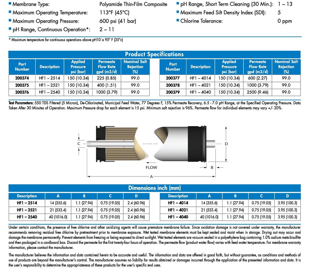
9 HF1-STANDARD 9
10 HF4-OPTIONAL 10
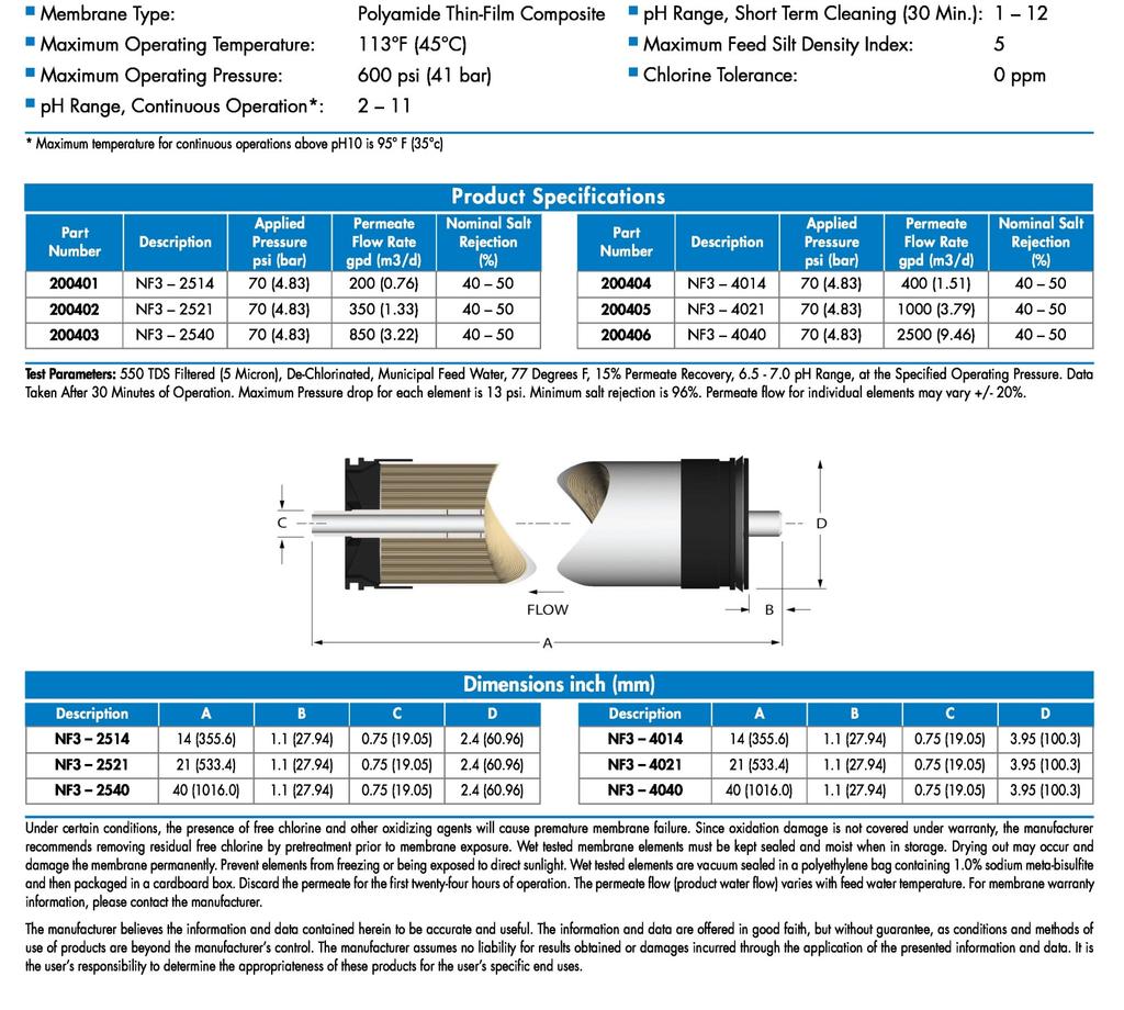
11 NF3-OPTIONAL 11
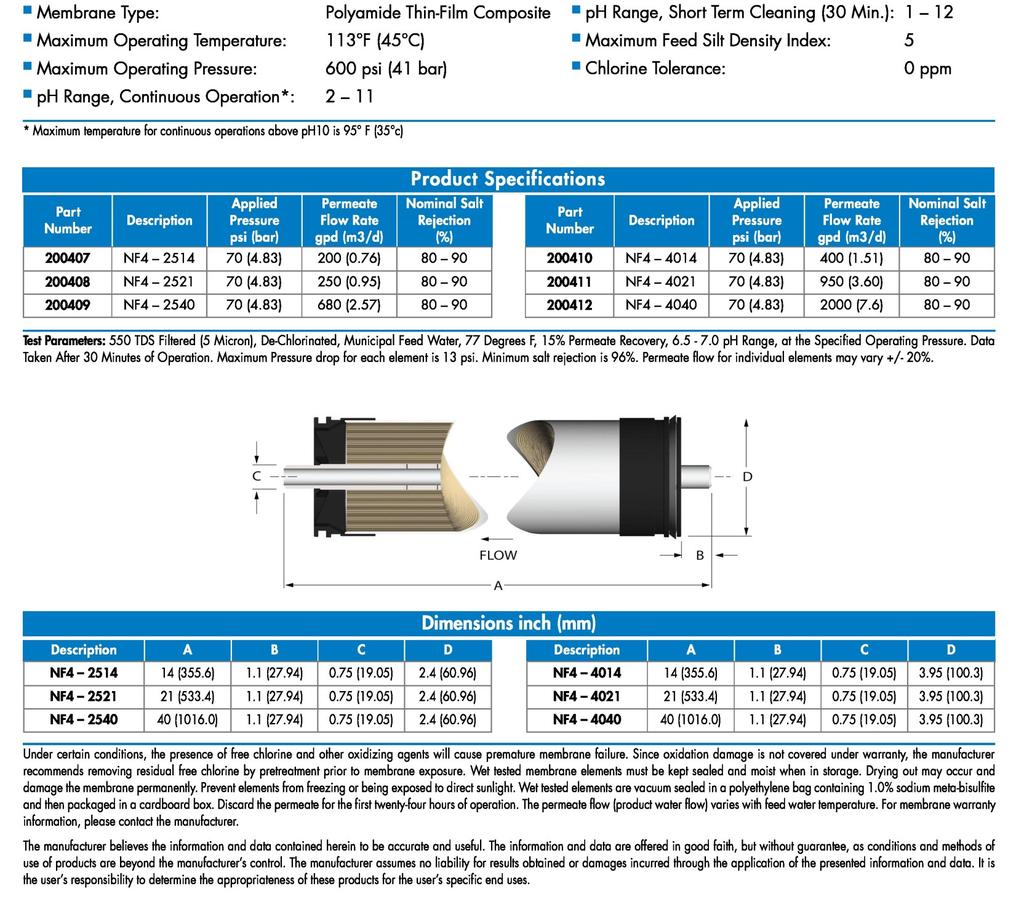
12 NF4-OPTIONAL 12
13 BT-1500, BT-1800, BT-2000 SYSTEM IDENTIFICATION FIGURE 1A NUMBER IDENTIFICATION 1. Solenoid Valve Turns On/Off Feed Water 2. 5 Micron Sediment Removes particulates Micron Carbon Block Chlorine reduction 4. Pressure Gauge - Measures feed pressure 5. Pressure Gauge - Measures pressure after filters 6. Control Switch - Controls RO system 7. Recycle Valve Recycles concentrate back to feed (if applicable) 8. Concentrate Valve Controls flow of concentrate (waste) water to the drain 9. RO Pump - Pressurizes RO System 10. Flow Meter - Measures flow of permeate water 11. Flow Meter - Measures flow of concentrate (waste) water 12. Flow Meter - Measures flow of concentrate recycle water (if applicable) 13. Pressure Gauge Measures Pump discharge pressure 14. Pressure Switch Turns the Pump off at less than 15 PSI feed pressure 15. Permeate Check Valve- Protects membranes from back pressure 16. Pressure Vessels Houses Membrane Elements 13
14 FIGURE 1B FIGURE 1C 14
15 FIGURE 1D FIGURE 1E 15
16 FIGURE 1F Note: A portion of the frame has been removed to expose components. 16
17 BT-1500 MEMBRANE FLOW DIAGRAM FIGURE 1G Note: Black arrows represent concentrate water and white arrows represent permeate water. 17
18 BT-1800 MEMBRANE FLOW DIAGRAM FIGURE 1H Note: Black arrows represent concentrate water and white arrows represent permeate water. 18

19 BT-2000 MEMBRANE FLOW DIAGRAM FIGURE 1I Note: Black arrows represent concentrate water and white arrows represent permeate water. 19
20 SYSTEM PURGING Carefully inspect your system before initial start-up. Check that all plumbing and electrical connections are not loose or have not come undone during shipment. A user s manual, test results, and filter housing wrench will accompany your BT-Series reverse osmosis system. NOTE: LEAVE THE POWER TO THE SYSTEM OFF FOR THIS PROCEDURE. 1. Redirect permeate water to the drain for this procedure. 2. Fully open the concentrate valve #8 (counter clockwise). (Figure 1B, Page 14) 3. Fully close the recycle valve # 7 (clockwise) (if applicable). (Figure 1B, Page 14) 4. Offset the position of the bypass white lever on the solenoid valve #1. (Figure 2, Page 20) 5. Turn the feed water on and let the system purge until no visible bubbles appear from concentrate flow meter #11. (Figure 1B, Page 14) Lever Inline Operating Position Lever Offset Bypass Position FIGURE 2 20
21 INITIAL START-UP 1. Keep the permeate water line to drain for this procedure. 2. Fully open the concentrate valve #8 (counter clockwise). (Figure 1B, Page 14) 3. Fully close the recycle valve # 7(clockwise)(if applicable). (Figure 1B, Page 14) 4. Return position of the bypass white lever inline on the solenoid valve #1. (Figure 2, Page 20) 5. Turn the RO system on #6 and adjust the concentrate (waste) valve #8, recycle valve # 7 (if applicable), and the bypass screw on the pump to the designed flow and pressure. (Figure 3, Page 25) 6. Inspect the system for leaks. 7. Allow the system to run for one hour to flush the preservative solution from the system. 8. After one hour, shut down the system. 9. Re-direct the permeate water back to the tank and then turn the system back on. 10. Record the readings daily for a week. After a week, record the readings once a week. Adjust the pump bypass valve and concentrate valve until the correct flow is achieved. For example, BT-1500 should be adjusted until it produces about 1500 GPD or 1.04 GPM of permeate (product water) at 77 F. Design flow might be achieved below 150 PSI. GPM = GPD/1440 Example: 1.04 =1500/
22 DESIGN BASIS FOR BT-1500, BT-1800, BT WARNING: NEVER EXCEED THE MAXIMUM PRESSURE RATING OF YOUR SYSTEM. MKTF /12
23 DO: Change the cartridge filters regularly OPERATING DO s AND DON Ts Monitor the system and keep a daily log Run the system as much as possible on a continuous basis Adjust the system recovery to the recommended value Always feed the pump with filtered water DON T Permit chlorine to enter or be present in the feed water Shut down the system for extended periods Close the throttle valve completely Operate the system with insufficient feed flow Operate the pump dry OPERATION AND MAINTENANCE The reverse osmosis process causes the concentration of impurities. The impurities may precipitate (come out of solution) when their concentration reaches saturation levels. NOTE: PRECIPITATION CAN SCALE OR FOUL MEMBRANES AND MUST BE PREVENTED. Check your feed water chemistry and pre-treat the water and/or reduce the system s recovery as required. If necessary, consult with your local dealer or distributor. 23
24 PRE-FILTER PRESSURE GAUGES These gauges measure the feed water pressure when it enters and exits the pre-filters. A pressure differential of psi or more on the two pressure gauges indicates that the pre-filters require servicing. For example, if the inlet pressure is 40 psi, the filter should be changed when the outlet pressure is 30 psi or below. PERMEATE (PRODUCT) FLOW METER AND CONCENTRATE (WASTE) FLOW METER These flow meters indicate the flow rates of the permeate and concentrate water. The measurements, when added together, also indicate the feed water flow rate or (total flow rate); if the system is not equipped with a concentrate recycle valve. CAUTION: EXCESSIVE RECYCLING MAY CAUSE PREMATURE FOULING OR SCALING OF THE MEMBRANE ELEMENTS. LOW PRESSURE SWITCH The low pressure switch shuts off the system when the feed water pressure drops below 15 PSI, preventing damage to the pump. The system restarts automatically when there is a constant pressure of 35 PSI or more. If you notice the pressure fluctuating, and the system cycling off and on, turn the system off and ensure that proper feed flow and pressure are available to the system. PUMP BYPASS VALVE This valve is installed as a standard feature on the BT-Series reverse osmosis systems. It provides an adjustment for pump pressure, which will vary as the required system pressure changes. As the feed water temperature decreases, and/or the feed water TDS increases, the system will require a higher operating pressure to produce the specified permeate flow. A BT system installed in Florida may provide the specified permeate flow of 1.04 gpm at 100 psi; however the same system installed in Maine much colder feed water may require 150 psi to produce the same amount of permeate. Never exceed 150 psi. 24
25 Example: 98.5% = [( )/550] x 100 % Rejection = (Feed TDS Product TDS)/ (Feed TDS) x 100 ADJUSTING THE BYPASS VALVE Use a fat screw driver to increase or decrease the pressure to the bypass valve. To increase the pressure, turn the screw clockwise. To decrease the pressure, turn the screw counter clockwise. (See Figure 3, Page 25) FIGURE 3 25
26 MEMBRANEE REMOVAL AND REPLACEMENT Replacing membranes in the pressure vessels is an easy process if you have the proper information and tools at hand. Please refer to the following instructions when removing and replacing membrane elements: WARNING: ALL PRESSURE GAUGES MUST READ ZERO BEFORE PROCEEDING. BEFORE ATTEMPTING, DISCONNECT THE POWER FROM THE SYSTEM AND BLEED ALL WATER PRESSURE FROM THE SYSTEM. 1. Remove the end caps from the top of the membrane housings. This is done by removing the white snap ring of the membrane housing. 2. Remove the membranee bag containing the membrane element from the shipping box. WEAR GLOVES FOR THE FOLLOWING STEPS IN ORDER NOT TO CONTAMINATE THE MEMBRANE. 3. Cut the bag open as close as possible to the seal at the end of the bag, so the bag may be re-used if necessary. 4. Make sure that all parts are clean and free from dirt. Examine the brine seal and permeate tube for nicks or cuts. Replace the O-rings or brine seal if damaged. 5. Flow directions should be observed for installation of each element into each housing. (Figure 4, Page 28) As time progresses, the efficiency of the membrane will be reduced. In general, the salt rejection does not change significantly until two or three years after installation when operated on properly pretreated feed water. The permeate flow rate will begin to decline slightly after one year of operation, but can be extended with diligent flushing and cleaning of the system. A high ph and/or precipitation of hardness can cause premature loss in rejection. MKTF /12
27 REPLACING THE MEMBRANE ELEMENT: WARNING: THE BRINE SEAL MUST BE IN THE SAME POSITION FOR EACH MEMBRANE ELEMENT HOUSING, SO MARK EACH HOUSING PRIOR TO REMOVING THE MEMBRANE ELEMENTS. THE BRINE SEAL IS A RUBBER SEAL THAT PROTRUDES ON ONE SIDE OF THE MEMBRANE AND IS ALWAYS ON THE FEED SIDE OF THE MEMBRANE ELEMENT. 1. Remove one membrane element at a time from the membrane element housings, from the top of the housing. Long nose pliers may be necessary to pull the old membrane element out of the membrane element housing. 2. Lubricate the brine seal with non petroleum based lubricant, Silicone DC Install the brine seal side of the membrane element first (Figure 4, Page 28). When the housings have a direction of flow from bottom to top, the brine seal should be located at the bottom of the housing. 4. At a slight angle, insert the membrane while slightly rotating the element being careful not to tear or flip the brine seal. A slow twisting motion should be used to insert the membrane element, to ensure the brine seal stays in place. Re-lube the brine seal if necessary. 5. With a smooth and constant motion, push the membrane element into the housing so the brine seal enters the housing without coming out of the brine seal groove. 6. Re-install the end caps by gently twisting the end cap while pushing it onto the housing. Ensure that you do not pinch or fatigue any O-rings while re-installing the end plug. Push the end plug on until the outer diameter of the plug is flush with the outer diameter of the membrane housing. 7. Insert the snap ring until it is fully seated. Install the locking clip if available. 8. Reconnect any fittings that may have been disconnected when the membrane element housings weree disassembled. 9. To start-up the system, please refer to the Initial Start-Up section of this manual. (See Page 21) CAUTION: WET MEMBRANES ARE SHIPPED IN A PRESERVATIVE SOLUTION. THE MEMBRANES MUST BE FLUSHED FOR AT LEAST 1 HOUR TO REMOVE THE PRESERVATIVE FROM THE MEMBRANE. DISCARD ALL OF THE PERMEATE AND CONCENTRATE, WHICH IS PRODUCED DURING THE FLUSH PERIOD. MKTF /12
28 FIGURE 4 View from the back of BT-1500, BT-1800, and BT-2000 reverse osmosis system. 28
29 FLUSHING THE SYSTEM The system should be flushed weekly to remove sediment from the surface of the membranes. To manually flush the system, follow the preceding steps: 1. The system must be operating during the flush procedure. 2. Fully open the concentrate valve. (Figure 1B, Page 14) 3. Allow the system to run for 10 to 20 minutes. 4. After 10 to 20 minutes, close the concentrate valve to its previous setting. Ensure the proper concentrate flow rate is going to the drain. 5. The system is now ready to operate. PREPARING UNIT FOR STORAGE OR SHIPMENT Prior to shipping or storing your system, the system should be cleaned with an appropriate cleaner, flushed with water and protected from biological attack with an appropriate solution for membrane elements. The membrane housing(s) and plumbing lines of the system must be completely drained. Any water remaining in the plumbing of a system may freeze, causing serious damage. Preparing system for storage: 1. Totally immerse the elements in the membrane housing in a solution of 2 % Memstor, venting the air outside of the pressure vessels. Use the overflow technique: circulate the Memstor solution in such a way that the remaining air in the system is minimized after the recirculation is completed. After the pressure vessel is filled, the Memstor solution should be allowed to overflow through an opening located higher than the upper end of the highest pressure vessel being filled. 2. Separate the preservation solution from the air outside by closing all valves. Any contact with oxygen will oxidize the Memstor. 3. Check the ph once a week. When the ph becomes 3 or lower, change the preservation solution. 4. Repeat this process at least once a month. During the shutdown period, the plant must be kept frost-free, or the temperature must not exceed 113 F (45 C). 29
30 Preparing unit for shipment: 5. Disconnect the inlet, concentrate, pre-filter, and permeate plumbing. 6. Drain all water from the pre-filter cartridge housings by unscrewing the housings, removing the pre-filter cartridges, and drain the water from the housings. 7. Disconnect the tubing from the connectors on the permeate and concentrate inlets and outlets. 8. Fully open the concentrate valve. 9. Drain the flow meters. 10. Allow the system to drain for a minimum of eight hours or until the opened ports quit dripping. 11. After draining is complete, reconnect all of the plumbing. 30
31 REVERSE OSMOSIS TROUBLESHOOTING SYMPTOMS POSSIBLE CAUSES CORRECTIVE ACTION Low Inlet Pressure Low Permeate Flow High permeate flow Poor permeate quality Membrane fouling Low supply pressure Cartridge filters plugged Solenoid valve malfunction Motor may not be drawing correct current Concentrate valve might be damaged Leaks Low inlet flow Cold feed water Low operating pressure Defective membrane brine seal Fouled or scaled membrane Damaged product tube o-rings Damaged or oxidized membrane Exceeding maximum feed water temperature Low operating pressure Damage product tube o-rings Damaged or oxidized membrane Metal Oxide Fouling Colloidal Fouling Scaling (CaSO4, CaSO3, BaSO4, SiO2) Biological Fouling Organic Fouling Chlorine Oxidation Abrasion of membrane by Crystalline Material Increase inlet pressure Change filters Replace sol. valve and/or coil Use clamp-on amp meter to check the motor amp draw. Replace needle valve Fix any visible leaks Adjust concentrate valve See temperature correction sheet See low inlet pressure Inspect and/or replace brine seal Clean membranes Inspect and/or replace Replace membrane See temperature correction sheet See low inlet pressure Inspect and/or replace Replace membrane Improve pretreatment to remove metals. Clean with acid cleaners. Optimize pretreatment for colloid removal. Clean with high ph anionic cleaners. Increase acid addition and antiscalant dosage for CaVO3 and CaCO4. Reduce recovery. Clean with acid cleaners Shock dosage of Sodium Bi-Sulfate. Continuous feed of Sodium Bi- Sulfate at reduced ph. Chlorination and de-chlorination. Replace cartridge filters. Activated Carbon or other pretreatment. Clean with high ph cleaner. Check Chlorine feed equipment and de-chlorination system. Improve pretreatment. Check all filters for media leakage. 31
32 ABNORMAL PERMEATE FLOW Permeate flow should be within 20% of the rated production, after correcting the feed water temperatures above or below 77 F. Check your permeate flow meter to determine the permeate flow rate. NOTE: TO DETERMINE THE TEMPERATURE CORRECTION FACTOR, LOCATE THE TEMPERATURE CORRECTION TABLE IN THIS USER S MANUAL AND FOLLOW THE DIRECTIONS 32

33 TEMPERATURE CORRECTION FACTORS FOR MEMBRANE Find the temperature correction factor (TCF) from the table below. Divide the rated permeate flow at 77 F by the temperature correction factor. The result is the permeate flow at the desired temperature. (See example on the next page) 33
34 If a system is rated to produce 5 gpm of permeate 77 F, the same system will produce more water at a higher temperature. It will also produce less water at a lower temperature. Use the temperature correction table to obtain the correct flow. Example: 5 59 F (5 1.42=3.52 gpm) 5 77 F (5 1=5 gpm) 5 84 F (5 0.89=5.62 gpm) SERVICE ASSISTANCE If service assistance is required, please complete the following process: Contact your local dealer or distributor. Prior to making the call, have the following information available: system installation date, serial number, daily log sheets, current operating parameters (e.g. flow, operating pressures, ph, etc.) and a detailed description of the problem. 34
35 OPERATION Company: Date of Start- Up: Location: Date of Last Cleaning: Week Of: System Serial #: Date Time Hour of Operation Filter inlet pressure (psi) Filter outlet Pressure (psi) Concentrate Pressure (psi) Pump Discharge Pressure (psi) Feed Flow (gpm) Permeate Flow (gpm) Concentrate Flow (gpm) Recovery % Feed Temperature Feed TDS (ppm) Permeate TDS (ppm) Rejection % Feed PH Permeate PH Scale Inhibitor Feed (ppm) Iron (mg/l) Free Chlorine (mg/l) Hardness (gpg CaCO3) 35
36 DRAWINGS FIGURE 5 36
37 Note: A portion of the frame has been removed to expose components. FIGURE 6 37
38 FIGURE 7 38
39 FIGURE 8 39
40 BT-1500 SYSTEM PART LIST Item No. Qty. Part No. Description GAUGE, BTM, NO FILL, 0-100PSI/BAR, 2 DIA VALVE, SOLENOID, N/C, UL, 110V, 1 FNPT CART, SEDIMENT, POLYPRO, 4.5 x 20, 5 MIC CARTRIDGE, CARBON, BLOCK, 4.5 x 20, 10 MIC HOUSING, FILTER, BLK/BLU, 4.5 x 20, 1 FNPT METER, FLOW, PM, 0-5GPM, 1/2 x 1/2 MNPT METER, FLOW, PM, 0-2GPM, 1/2 x 1/2 MNPT GAUGE, BKM, FILL, 0-300PSI/BAR, 2.5 DIA SWITCH, ON/OFF, SINGLE POLE, 110V BOX, SWITCH, GANG, SINGLE, PROOF, WEATHER VALVE, NEEDLE, SS 316L, 1/4" FNPT, PUROTECH VALVE, CHECK, PP, 3/8 FNPT x 3/8 FNPT SWITCH, PRESSURE, LOW, N/O 15-30, 1/4 FNPT MOTOR, CARB, 3/4" HP, 110/220V, 50/60 HZ PUMP, VANE, BRASS, BYPASS, 5.3GPM, MEM, HF1, 2540, SYSTEMS MHS, PVC, 2540, 3/8 x 3/8 SP FNPT, SYSTEMS SNAP RING, DELRIN, END PLUG, OPEN, GTX, 2.5, 3/8 FNPT END CLOSED, OPEN, GTX, 2.5, 3/8 FNPT CLAMP, SADDLE, NYLON, BLK, 2.5, PVC 40
41 BT-1800 SYSTEM PART LIST Item No. Qty. Part No. Description GAUGE, BTM, NO FILL, 0-100PSI/BAR, 2 DIA VALVE, SOLENOID, N/C, UL, 110V, 1 FNPT CART, SEDIMENT, POLYPRO, 4.5 x 20, 5 MIC CARTRIDGE, CARBON, BLOCK, 4.5 x 20, 10 MIC HOUSING, FILTER, BLK/BLU, 4.5 x 20, 1 FNPT METER, FLOW, PM, 0-5GPM, 1/2 x 1/2 MNPT METER, FLOW, PM, 0-2GPM, 1/2 x 1/2 MNPT GAUGE, BKM, FILL, 0-300PSI/BAR, 2.5 DIA SWITCH, ON/OFF, SINGLE POLE, 110V BOX, SWITCH, GANG, SINGLE, PROOF, WEATHER VALVE, NEEDLE, SS 316L, 1/4" FNPT, PUROTECH VALVE, CHECK, PP, 3/8 FNPT x 3/8 FNPT SWITCH, PRESSURE, LOW, N/O 15-30, 1/4 FNPT MOTOR, CARB, 3/4" HP, 110/220V, 50/60 HZ PUMP, VANE, BRASS, BYPASS, 5.3GPM, MEM, HF1, 4040, SYSTEMS MHS, PVC, 4040, 1/2 x 1/2 SP FNPT, SYSTEMS SNAP RING, DELRIN, END PLUG, OPEN, GTX, 4, 1/2 FNPT END CLOSED, OPEN, GTX, 4, 1/2 FNPT CLAMP, SADDLE, NYLON, BLK, 4, PVC 41
42 BT-2000 SYSTEM PART LIST Item No. Qty. Part No. Description GAUGE, BTM, NO FILL, 0-100PSI/BAR, 2 DIA VALVE, SOLENOID, N/C, UL, 110V, 1 FNPT CART, SEDIMENT, POLYPRO, 4.5 x 10, 5 MIC CARTRIDGE, CARBON, BLOCK, 4.5 x 10, 10 MIC HOUSING, FILTER, BLK/BLU, 4.5 x 20, 1 FNPT METER, FLOW, PM, 0-5GPM, 1/2 x 1/2 MNPT METER, FLOW, PM, 0-2GPM, 1/2 x 1/2 MNPT GAUGE, BKM, FILL, 0-300PSI/BAR, 2.5 DIA SWITCH, ON/OFF, SINGLE POLE, 110V BOX, SWITCH, GANG, SINGLE, PROOF, WEATHER VALVE, NEEDLE, SS 316L, 1/4" FNPT, PUROTECH VALVE, CHECK, PP, 3/8 FNPT x 3/8 FNPT SWITCH, PRESSURE, LOW, N/O 15-30, 1/4 FNPT MOTOR, CARB., 3/4" HP, 110/220V, 50/60 HZ PUMP, VANE, BRASS, BYPASS, 5.3GPM, MEM, HF1, 2540, SYSTEMS MHS, PVC, 2540, 3/8 x 3/8 SP FNPT, SYSTEMS SNAP RING, DELRIN, END PLUG, OPEN, GTX, 2.5, 3/8 FNPT END CLOSED, OPEN, GTX, 2.5, 3/8 FNPT CLAMP, SADDLE, NYLON, BLK, 2.5, PVC 42
43 BT-1500 FLOW DIAGRAM 43
44 BT-1800 FLOW DIAGRAM 44
45 BT-2000 FLOW DIAGRAM 45
46 110V ELECTRICAL SCHEMATIC 46
47 220V ELECTRICAL SCHEMATIC 47
48 48
This Page Left Blank 2
 Reverse Osmosis User s Manual Model DT-10000, DT-15000, DT-20000 DT-20000 Pictured This Page Left Blank 2 Table of Contents INTRODUCTION... 4 SAFETY... 4 FEED WATER AND OPERATION SPECIFICATIONS... 5 REJECTION,
Membrane System User s Manual
 Membrane System User s Manual Model IH2O: 2000-8000 Series IH2O 4000 PICTURED This Page Left Blank MKTF-357` 2 9/14 TABLE OF CONTENTS INTRODUCTION 4 SAFETY 5 FEED WATER AND OPERATION SPECIFICATIONS 7 REJECTION,
Membrane System User s Manual. L1-Series
 Membrane System User s Manual L1-Series This Page Left Blank MKTF-258 2 9/14 TABLE OF CONTENTS INTRODUCTION... 4 SAFETY... 5 FEED WATER AND OPERATION SPECIFICATIONS... 6 REJECTION, RECOVERY AND FLOW RATES...
Reverse Osmosis User s Manual
 Reverse Osmosis User s Manual Models InteliPure IP-2000 Table of Contents Introduction...3 Safety...3 Labeling...3 System Specifications...3 Feed Water & Operation Specifications...4 Rejection, Recovery,
Reverse Osmosis Manual
 Reverse Osmosis Manual H-Series Models HT-250, HT-500 HT-1000, HT-1500, HT-2500 INTRODUCTION Your reverse osmosis system is a durable piece of equipment which, with proper care, will last for many years.
Reverse Osmosis User s Manual
 Reverse Osmosis User s Manual J-Series Models JT-2000, JT-4000 INTRODUCTION Your Titan J-Series reverse osmosis system is a durable piece of equipment which, with proper care, will last for many years.
Owners Manual Models: 200-USCRO-600FR. US Water 600 GPD Floor-Mount Light Commercial Economy RO System. Visit us online at
 Visit us online at www.uswatersystems.com US Water 600 GPD Floor-Mount Light Commercial Economy RO System Owners Manual Models: 200-USCRO-600FR REVISION # 1.2 REVISION DATE June 27 2017 US Water Systems
Spot Zero Mobile Wash Down System SZMWD SZMWDWH 110v SZ MWDZ SZ MWDZ WH 220v
 md Dometic SPBT ZERO Spot Zero Mobile Wash Down System 0111212015 SZMWD SZMWDWH 110v SZ MWDZ SZ MWDZ WH 220v 2000 N Andrews Ext. Pompano Beach, FL 33069 Phone 954-973-2477 Fax 954-979-4414 Email: info@spotzerowater.com
REVERSE OSMOSIS INSTALLATION AND OPERATION MANUAL. R12-Wall Mount
 REVERSE OSMOSIS INSTALLATION AND OPERATION MANUAL R12-Wall Mount IMPORTANT Please read the entire manual before proceeding with the installation and startup: Do not use where the water is microbiologically
The motors used on Thunder 500, 1000, 1500, 1800 and 2500 systems are carbonator motors. They are available in 110/220 volt 50/60 hertz 1 phase.
 ELECTRICAL The motors used on Thunder 500, 1000, 1500, 1800 and 2500 systems are carbonator motors. They are available in 110/220 volt 50/60 hertz 1 phase. Please ensure that the electrical circuit supplying
PURE WATER. Installation, Operation and Maintenance Manual. Wall Mounted Commercial Reverse Osmosis Systems. Series PWR2511. Table Of Contents.
 Installation, Operation and Maintenance Manual Wall Mounted Commercial Reverse Osmosis Systems Series PWR2511 IOM-WQ-PWR2511 PURE WATER! WARNING Please read carefully before proceeding with installation.
PURE WATER. Installation, Operation and Maintenance Manual. Reverse Osmosis System Series PWRO440. Important. Notes. Table of Contents IOM-WQ-PWRO440
 Installation, Operation and Maintenance Manual Reverse Osmosis System Series PWRO440 IOM-WQ-PWRO440 PURE WATER Important Please read the entire manual before proceeding with the installation and startup:
Crystal Quest Thunder Reverse Osmosis INSTALLATION AND OPERATION GUIDE
 Crystal Quest Thunder Reverse Osmosis INSTALLATION AND OPERATION GUIDE MODELS 4000, 5000, & 7000 ONLINE WARRANTY INFORMATION CrystalQuest.com/warranty.html Copyright 2018 Crystal Quest All rights reserved
MASTER. Water Conditioning Corp. OPERATION MANUAL. PURO PRO 1200 SCP Series Modular Reverse Osmosis System. January 2012 Version
 MASTER Water Conditioning Corp. www.masterwater.com OPERATION MANUAL PURO PRO 1200 SCP Series Modular Reverse Osmosis System January 2012 Version Table of Contents Model Number... 1 Shipping Description
MASTER. Water Conditioning Corp. OPERATION MANUAL. PURO PRO 1200 SC Series Modular Reverse Osmosis System. January 2012 Version
 MASTER Water Conditioning Corp. www.masterwater.com OPERATION MANUAL PURO PRO 1200 SC Series Modular Reverse Osmosis System January 2012 Version Table of Contents Model Number... 1 Shipping Description
Thunder Reverse Osmosis
 CRYSTAL QUEST Thunder Reverse Osmosis Installation and Maintenance Instructions MODELS 10,000, 15,000, & 20,000 CRYSTAL QUEST Copyright 2017 All rights reserved. Made in the USA COMPONENTS Introduction
Mission Statement. Profile and History. R.O. UltraTec s Advantages
 2005 PRODUCT CATALOG» Reverse Osmosis Systems» Water Coolers» Filter Cartridges» Filter Housings» Filtration Systems & Water Softeners» Membrane Housings» Membranes» Pumps & Motors» Disinfection Equipment
Feed Water Specifications Free Chlorine <0 ppm Manganese <0.05 ppm Total Dissolved Solids <2000 ppm Organics <1 ppm Turbidity (SDI) <5 Silica <1 ppm
 <5 Silica <1 ppm") Waste Connection 1" 1" 1" Minimum Feed (gpm) 6 7 10 Recovery* 33%-50% 33%-50% 33%-50% * Recovery ratio may vary between 33% - 50% and up to 75% if system projections have been provided. Feed Water & Operation
Waste Connection 1" 1" 1" Minimum Feed (gpm) 6 7 10 Recovery* 33%-50% 33%-50% 33%-50% * Recovery ratio may vary between 33% - 50% and up to 75% if system projections have been provided. Feed Water & Operation
PSP Series Water Purification Systems
 Operations and Maintenance Manual for PSP Series Water Purification Systems PSP-1000 PSP-1600 PSP-2700 Rev. 2 / 08/26/14 Compact Design, Self-Contained Water Processing Unit for Point-Of-Use or Point-Of-Entry
Installation, Operation, and Maintenance Manual Aquapurion 600 GPD Line Pressure Reverse Osmosis System
 Installation, Operation, and Aquapurion 600 GPD Line Pressure Reverse Osmosis System US Water Systems, Inc. 1209 Country Club Road Indianapolis, IN 46234 1-800-608-8792 support@uswatersystems.com www.uswatersystems.com
NOTES P: 888-H2O-LOGIC ( ) F:
 F:") NOTES P: 888-H2O-LOGIC (426-5644) F: 831-336-9840 info@hydrologicsystems.com www.hydrologicsystems.com BEFORE INSTALLING THE RO SYSTEM WARRANTY Best performance of the system will be achieved when the
NOTES P: 888-H2O-LOGIC (426-5644) F: 831-336-9840 info@hydrologicsystems.com www.hydrologicsystems.com BEFORE INSTALLING THE RO SYSTEM WARRANTY Best performance of the system will be achieved when the
REVERSE OSMOSIS. MODELS MRO GPD (For models manufactured November 2012 and beyond.) INSTALLATION, OPERATION, AND MAINTENANCE MANUAL
 INSTALLATION, OPERATION, AND MAINTENANCE MANUAL") REVERSE OSMOSIS MODELS MRO-2.5 500 GPD (For models manufactured November 202 and beyond.) INSTALLATION, OPERATION, AND MAINTENANCE MANUAL COMPLETE FOR FUTURE REFERENCE: MODEL NO: SERIAL NO: DATE INSTALLED:
REVERSE OSMOSIS MODELS MRO-2.5 500 GPD (For models manufactured November 202 and beyond.) INSTALLATION, OPERATION, AND MAINTENANCE MANUAL COMPLETE FOR FUTURE REFERENCE: MODEL NO: SERIAL NO: DATE INSTALLED:
Premium Water Filtration Systems
 SETUP AND MAINTENANCE GUIDE Premium Water Filtration Systems RO SYSTEM 150 GPD Product # 738300 & Product # 738306 RO SYSTEM 300 GPD Product # 738305 & Product # 738308 WHAT S IN THE BOX? Premium Water
RO400 USER'S MANUAL. Memo PURE-PRO REVERSE OSMOSIS SYSTEM RO400. Type of product. Date of purchase. Address
 Type of product RO400 Memo Date of purchase Name Address Tel REVERSE OSMOSIS SYSTEM 19 RO400 USER'S MANUAL 01 Introduction of RO400 02 What is Reverse Osmosis 03 Components& Selections 04 Cartridge filters
SETUP AND MAINTENANCE GUIDE
 SETUP AND MAINTENANCE GUIDE 100 GPD Classic RO System Product # 8 200 GPD Classic RO System Product # 88 WHAT S IN THE BOX? IDEAL H 2 O REVERSE OSMOSIS 100 GPD PART LIST: Reverse Osmosis - 100 GPD Three
REVERSE OSMOSIS SYSTEM INSTALLATION, OPERATION, AND MAINTENANCE MANUAL
 REVERSE OSMOSIS SYSTEM INSTALLATION, OPERATION, AND MAINTENANCE MANUAL Table of Contents REVERSE OSMOSIS SYSTEM...1 1. INTRODUCTION...1 2. SYSTEM INFORMATION...1 3. INSTALLATION...2 4. FEED WATER SPECIFICATIONS...3
Mar Cor Purification. Carbon Block Filtration System. Operation & Maintenance Manual
 Mar Cor Purification Carbon Block Filtration System Operation & Maintenance Manual 3027337 Rev. B 8Jan13 3027337 Rev. B 8Jan13 Operation & Maintenance Manual Table of Contents Page CHAPTER ONE: GENERAL
S800-Direct Flow USER'S MANUAL. Memo REVERSE OSMOSIS SYSTEM. Type of product. Date of purchase. Address
 Memo Type of product S800-Direct Flow Date of purchase Name Address Tel REVERSE OSMOSIS SYSTEM 15 S800-Direct Flow USER'S MANUAL 01 Introduction of S800-Direct Flow 02 What is reverse osmosis 03 Components
SRO-1000 SRO-2000 SRO-4000 INSTALLATION MANUAL US 33 N. Churubusco, IN Ph. (260) Fax (260)
 Fax (260)") INSTALLATION MANUAL SRO-1000 SRO-2000 SRO-4000 SRO-1000 pictured 12630 US 33 N. Churubusco, IN 46723 Ph. (260)693-1972 Fax (260)693-0602 www.sterlingwatertreatment.com SRO-1000 through SRO-4000 (170203).docx
INSTALLATION MANUAL SRO-1000 SRO-2000 SRO-4000 SRO-1000 pictured 12630 US 33 N. Churubusco, IN 46723 Ph. (260)693-1972 Fax (260)693-0602 www.sterlingwatertreatment.com SRO-1000 through SRO-4000 (170203).docx
COMMERCIAL REVERSE OSMOSIS. Installation Considerations. Model C350
 COMMERCIAL REVERSE OSMOSIS Installation Considerations Model C350 COMMERCIAL REVERSE OSMOSIS Installation Requirements The C350 system is to be used on potable water only. If there is a hot water heater,
ERS-106UV USER'S MANUAL. Memo PURE-PRO REVERSE OSMOSIS SYSTEM. Type of product. Date of purchase. Address
 Type of product Memo Date of purchase Name Address Tel REVERSE OSMOSIS SYSTEM 15 ERS-106UV USER'S MANUAL 01 Introduction of ERS-106UV 02 What is reverse osmosis 03 Components & Selected filters 04 Cartridge
Reverse Osmosis Purifiers
 Reverse Osmosis Purifiers Reverse Osmosis & Deionization (RO/DI) units are used in reef tanks and saltwater aquariums; all coral tanks need RO/DI water for initial water and make up water. RO/DI removes
Aqualife Products (Australia) Pty Ltd Steam Sterilisor Water System
 Pty Ltd Steam Sterilisor Water System") Aqualife Products (Australia) Pty Ltd Steam Sterilisor Water System AquaClave P5 REVERSE OSMOSIS WATER TREATMENT SYSTEM Attention USER S MANUAL 01 Introduction of AquaClave 02 What is reverse osmosis 03
Aqualife Products (Australia) Pty Ltd Steam Sterilisor Water System AquaClave P5 REVERSE OSMOSIS WATER TREATMENT SYSTEM Attention USER S MANUAL 01 Introduction of AquaClave 02 What is reverse osmosis 03
Advanced water purifier system operation manual and setup guide
 Advanced water purifier system operation manual and setup guide What is Reverse Osmosis? Reverse osmosis, also known as hyper filtration, is the finest filtration known. This process will allow the removal
Access manuals, spec sheets and additional educational materials for foodservice water treatment at our website.
 OP-70 Simple Install Guide Rev. 1.1 Access manuals, spec sheets and additional educational materials for foodservice water treatment at our website. www.optipurewater.com OP70_Simple_Install_v1-1.indd
FS-8000 USER'S MANUAL. Memo PURE-PRO REVERSE OSMOSIS SYSTEM. Type of product FS Date of purchase. Address
 Type of product FS-8000 Memo Date of purchase Name Address Tel REVERSE OSMOSIS SYSTEM 15 FS-8000 USER'S MANUAL 01 Introduction of FS-8000 02 What is Reverse Osmosis 03 Components& Selections 04 Cartridge
Features Reliable, DOW FILMTEC Membrane 4 - Stage Reverse Osmosis System - Part Number:
 REVERSE OSMOSIS MANUAL Features Reliable, DOW FILMTEC Membrane 4 - Stage Reverse Osmosis System - Part Number: 15-3000 Waterlogic Commercial Products, LLC 11710 Stonegate Circle Omaha, NE 68164 (800) 288-1891
Owners Manual Models: 200-RODI4-XXX. US Water Systems 4 Stage RO/DI System Installation and Maintenance Manual.
 Visit us online at www.uswatersystems.com US Water Systems 4 Stage RO/DI System Installation and Maintenance Manual Owners Manual Models: 200-RODI4-XXX US Water 4 Stage RO/DI System REVISION 1.0, 5/12/2015
ALAMO WATER REFINERS REVERSE OSMOSIS INSTALLATION AND OPERATION MANUAL. R14-Wall Mount
 ALAMO WATER REFINERS REVERSE OSMOSIS INSTALLATION AND OPERATION MANUAL R14-Wall Mount Alamo Water Refiners, Inc. 13700 Hwy. 90 West San Antonio, TX 78245 U.S.A. 210-677-8400 www.alamowater.com IMPORTANT
E4, E4LE, EZ4 Series
 E4, E4LE, EZ4 Series Water Purification Machines Operation and Maintenance Manual 2,200 GPD to 13,200 GPD 8.3 m 3 /day to 50 m 3 /day July 4, 2014 Document PN 1161875, Rev G http://www.gewater.com 1 TABLE
HRO-50 Water Purifier
 HRO-50 Water Purifier Product Installation & Operation Manual Honeywell Environmental & Combustion Controls (Tianjin) Co., Ltd. Content Important Notes P2 Product Functions P3-P5 Installation Instructions
REVERSE OSMOSIS SYSTEM USER'S MANUAL. Excellent Product, Excellent Water! My PurePro X6
 REVERSE OSMOSIS SYSTEM USER'S MANUAL UV Plus! Excellent Product, Excellent Water! My PurePro X6 PUREPRO X6 Thank you very much for selecting Pure-Pro Water Corp. In order to bring the best use of your
OPERATIONS AND MAINTENANCE MANUAL
 OPERATIONS AND MAINTENANCE MANUAL s 16,000 GPD to 43,200 GPD 60.6 m 3 /day to 163.5 m 3 /day NOTICE The enclosed materials are considered proprietary property of GE Water & Process Technologies. No assignments,
RO102 P URE PRO DRINKING WATER SYSTEM USER'S MANUAL. Memo REVERSE OSMOSIS SYSTEM. Type of product. Date of purchase. Address RO102
 Type of product RO102 Memo Date of purchase Name Address Tel REVERSE OSMOSIS SYSTEM PURE- REVERSE OSMOSIS SYSTEM 15 RO102 USER'S MANUAL 01 Introduction of RO102 02 What is reverse osmosis 03 Components
SGLP-RO. Installation and Operating Instructions for SCALEGARD TM LP REVERSE OSMOSIS FILTRATION SYSTEM. 3M TM Water Filtration Products
 3M TM Water Filtration Products Installation and Operating Instructions for SCALEGARD TM LP REVERSE OSMOSIS FILTRATION SYSTEM SGLP-RO Installer: Please leave this manual with owner/operator. LIMITED WARRANTY
AstroBoy Quick install guide
 AstroBoy Quick install guide Water Inlet connection Water can be diverted to the AstroBoy by either using the tap diverter or the opella valve. Tap diverter From your main kitchen mixer tap unscrew the
SRO70 Installation Manual
 SRO70 Installation Manual Rev. 2.2 SRO70_Simple_Install_v2-2.indd 2018 Procam Controls, Inc. All Rights Reserved Access manuals, spec sheets and additional educational materials for foodservice water treatment
Table of Contents BEFORE INSTALLATION INSTALLATION OPERATION MAINTENANCE TECHNICAL & WARRANTY INFORMATION
 Table of Contents BEFORE INSTALLATION Overview...1 Using Quick-Connect Fittings...2 System Maintenance...2 Installation Notes...2 Operational Parameters...3 Contents of the Reverse Osmosis (RO) System...3
OPERATIONS AND MAINTENANCE MANUAL. E8 Series Water Purification Machines
 OPERATIONS AND MAINTENANCE MANUAL s 57,000 GPD to 144,000 GPD 216 m 3 /day to 545 m 3 /day NOTICE The enclosed materials are considered proprietary property of GE Water & Process Technologies. No assignments,
Dear customer, Thank you for purchasing our company s water purifier. You now have water treatment equipment that is at the world s leading position
 Dear customer, Thank you for purchasing our company s water purifier. You now have water treatment equipment that is at the world s leading position in today s water treatment field. It produces pure water
3M Water Filtration Products Model SGLP-RO Reverse Osmosis System- Quick Installation Guide
 3M Water Filtration Products Model SGLP-RO Reverse Osmosis System- Quick Installation Guide Note: Installer - please leave with owner/operator. SAFETY INFORMATION Read, understand, and follow all safety
Commercial Reverse Osmosis Systems and Accessories
 Section 10 Commercial Reverse Osmosis Systems and Accessories R13 Compact Wall Mount RO Commercial Reverse Osmosis Systems And Accessories 249 Commercial Reverse Osmosis Systems And Accessories Specifications
OPERATION AND MAINTENANCE MANUAL UF-6-HF ULTRAFILTRATION SYSTEM
 OPERATION AND MAINTENANCE MANUAL UF-6-HF ULTRAFILTRATION SYSTEM Con-Serv Manufacturing 805 West Brannen Road Lakeland, FL 33813 (800) 868 9888 www.con-servwater.com Introduction This manual includes the
REVERSE OSMOSIS WATER TREATMENT
 REVERSE OSMOSIS WATER TREATMENT LTF 2, LTF 3 and LTF 4 SERIES RO SYSTEMS 14,400 TO 252,000 GALLONS PER DAY AND LARGER Lakeside Water for Affordable Pure Water Technology 1 P age Packaged Reverse Osmosis
DIE CAST ALUMINUM & THERMOPLASTIC SUMP PUMP
 INSTRUCTION MANUAL DIE CAST ALUMINUM & THERMOPLASTIC SUMP PUMP Vertical Switch Models WSSP3V 1/3 HP WSSP5V 1/2 HP Tethered Switch Models WSSP3 1/3 HP WSSP5 1/2 HP WARRANTY: PRODUCT DEFECTS COVERED 12 MONTHS
ChungHo Dealer Technical Guide
 ChungHo Dealer Technical Guide Recommendations Prior to Installation -Flush out the system -Check for leaks / hose connections -Test Board connections Installation Procedures -Basic POU Installation -Do
Owner s Manual Calcite Cartridge System
 Owner s Manual Calcite Cartridge System Page 2 Copyright 2011 Enviro Water Solutions, Inc. All rights reserved. All information contained herein is the property of Pelican Water Technologies. Pelican Water
REVERSE OSMOSIS SYSTEM
 REVERSE OSMOSIS SYSTEM Wall Mount (Hinged) Design INSTALLATION, OPERATION, AND MAINTENANCE MAUAL Table of Contents REVERSE OSMOSIS SYSTEM...3 1. INTRODUCTION...3 2. SYSTEM INFORMATION...3 2.1. FACTORY
P URE PRO DRINKING WATER SYSTEM USER'S MANUAL REVERSE OSMOSIS SYSTEM. Type of product. Date of purchase. Address
 International Reverse Osmosis System Standard Under Industry Standard #SBT-02204 Type of product UV-301 Memo Date of purchase Name Address Tel REVERSE OSMOSIS SYSTEM PURE- REVERSE OSMOSIS SYSTEM 15 U.S.A.
Membrane Technology: From Manufacture to. May Production
 Membrane Technology: From Manufacture to May 2018 Production Osmosis Graphic pulled from https://earthobservatory.nasa.gov/features/water/page2.php Water Sources Surface Waters Ground Water Seawater Lakes
1 YEAR FROM DATE OF PURCHASE
 INSTRUCTION MANUAL CAST IRON SUMP PUMP WSSPC5V 1/2 HP WARRANTY: PRODUCT DEFECTS COVERED 1 YEAR FROM DATE OF PURCHASE. RECEIPT AND PRODUCT DATE CODE REQUIRED FOR WARRANTY CLAIM. This pump is controlled
Commercial Reverse Osmosis System
 Commercial Reverse Osmosis System Aqua Clear Water Treatment Specialists manufacturers and engineers standard and custom commercial reverse osmosis systems water to accomodate many different water conditions.
Boss Water Systems Australia Reverse Osmosis System Model 021-4P-GM
 Boss Water Systems Australia Reverse Osmosis System Model 021-4P-GM Congratulations on your purchase of the most advanced water purifier system available! Installation and Service Guide short web version,
PURE-PRO REVERSE OSMOSIS SYSTEM
 REVERSE OSMOSIS SYSTEM 15 RO36000 Industrial RO System 01 Feed water quality requirement 01 System specifications 02 Part list 07 Installation 08 Operation process & maintenance 10 Trouble shooting 13
SRO-300 INSTALLATION MANUAL
 SRO-300 INSTALLATION MANUAL 12630 US 33 N. Churubusco, IN 46723 Ph. (260)693-1972 Fax (260)693-0602 www.sterlingwatertreatment.com 1 PRE-INSTALLATION Thank you for choosing the Sterling SRO Series commercial
YOUR SPLASH PAD RESOURCE
 1 Index Permits & Inspections Material List Warnings Splash Pad Types Pre-Site Grading Plumbing Schematic Pressure Testing Concrete Preparation and Pour Housing/Nozzle Installation Above Ground Water Feature
VaVie Water Purifier
 VaVie Water Purifier Installation instructions Thank you for purchasing VaVie water purifier. Please read the instructions carefully before using. Please keep this booklet for later reference. Model: WA75-A
Operating Guidelines Cleaning
 Technical Bulletin Operating Guidelines Cleaning Cleaning Pure Water Membrane Elements Introduction Regular cleaning of Desal membrane elements is important because foulants can build up on membrane surfaces,
RO105TDS P URE PRO DRINKING WATER SYSTEM USER'S MANUAL. Memo PRO REVERSE OSMOSIS SYSTEM. Type of product RO105TDS. Date of purchase.
 Power Good Bad Type of product RO105TDS Memo Date of purchase Name Address Tel REVERSE OSMOSIS SYSTEM PURE- REVERSE OSMOSIS SYSTEM 15 RO105TDS USER'S MANUAL 01 Introduction of RO105TDS 02 What is reverse
1000 GPD Marlin Reverse Osmosis Instruction & Owner s Manual
 1000 GPD Marlin Reverse Osmosis Instruction & Owner s Manual AQUAFX INSTALLATION INSTRUCTIONS Congratulations on your new AquaFX water treatment system from Aqua Engineering & Equipment, Inc. We hope your
REVERSE OSMOSIS SYSTEM INSTALLATION, OPERATION, AND MAINTENANCE MAUAL
 REVERSE OSMOSIS SYSTEM INSTALLATION, OPERATION, AND MAINTENANCE MAUAL Table of Contents REVERSE OSMOSIS SYSTEM...1 1. INTRODUCTION...1 2. SYSTEM INFORMATION...1 3. INSTALLATION...2 4. FEED WATER SPECIFICATIONS...3
1500G-3000G USER'S MANUAL. Trouble shooting
 Trouble shooting Problem Possible reason Solution System is not functioning 1.Controller box set at 0..The pressure of feed water isn't high enough. ( more than 1.5kg/cm ) 1.Make an adjustment..check water-in
Installation Manual for SGLP-CL Series Reverse Osmosis Filtration Systems
 3M Water Filtration Products Installation Manual for SGLP-CL Series Reverse Osmosis Filtration Systems SGLP100-CL SGLP100-CL-BP SGLP200-CL SGLP200-CL-BP Note: Installer - please leave with owner/operator.
Installation Manual /warranty/certification 600G Advanced Water Purifier
 Installation Manual /warranty/certification 600G Advanced Water Purifier Model: RO-75P-600 (The appearance is just for reference) Thank you for choosing this water purifier! Do read the installation booklet
USER'S MANUAL. Memo REVERSE OSMOSIS SYSTEM. Type of product. Date of purchase. Address EC Introduction of EC What is reverse osmosis
 Memo Type of product Date of purchase EC105 Name Address Tel REVERSE OSMOSIS SYSTEM USER'S MANUAL 01 Introduction of EC105 02 What is reverse osmosis 03 Components & Selected filters 04 Cartridge filters
Model T Professional Series 1/2HP 2 YEAR WARRANTY SUBMERSIBLE SUMP PUMP
 Model T00718 REPAIR PARTS REF. PART DESCRIPTION 1 310883 Upper casing 2 310885 Motor housing 3 310889 Stator 4 310887 Shaft / rotor 5 310895 Mechanical seal 6 310892 Impeller 7 310893 Strainer 8 310890
OPERATION AND MAINTENANCE MANUAL
 OPERATION AND MAINTENANCE MANUAL Pure Water Group P.O. Box 785 Calistoga, CA 94515 pure-water-group.com Toll Free: 310.993.9929 Pure Water Group 2015 puropod is Made in the USA Distributed by Pure Water
BG-PURE Reverse Osmosis Drinking Water System Performance Data Sheet
 BG-PURE Reverse Osmosis Drinking Water System Performance Data Sheet Model VTFC5G-PB is tested and certified by WQA against NSF/ANSI 58 for the reduction of TDS BG-PURE SYSTEM CONFIGURATION Table Model
WH5-2 Iron & Hydrogen Sulfide Reduction Filter Package
 WH5-2 Iron & Hydrogen Sulfide Reduction Filter Package Package Contents: one (1) heavy-duty Pentek Big Blue 20 filter housing (1 NPT) w/ pressure relief button one (1) stainless steel mounting bracket
You get more for less at FSHS!
 You get more for less at FSHS! www.puromax.com Phone (941)625 4550 Fax (941)625-6635 4210 Whidden Blvd. Port Charlotte, FL 33980 Phone (941)625-4550 Fax (941)625-6635 www.puromax.com Contacts President
AXEON Tap Water Reverse Osmosis Systems... SECTION 1. FLEXEON Tap Water Reverse Osmosis Systems... SECTION 2
 AXEON Tap Water Reverse Osmosis Systems.............. SECTION 1 AXEON CRO Series Reverse Osmosis System..................................... 1 2 AXEON L1 Series Reverse Osmosis Systems.......................................
Introduction of HR-800(M) Components. Cartridge filters. Installation diagram. Change membrane. Change filters. Operation regulation FAQ
 Components. Cartridge filters. Installation diagram. Change membrane. Change filters. Operation regulation FAQ") Introduction of HR-800(M) Components Cartridge filters Installation diagram Change membrane Change filters Operation regulation FAQ Maintenance checking list Memo Thank you very much for selecting Hyundai
Introduction of HR-800(M) Components Cartridge filters Installation diagram Change membrane Change filters Operation regulation FAQ Maintenance checking list Memo Thank you very much for selecting Hyundai
RS-106M-P USER'S MANUAL. Memo PURE-PRO REVERSE OSMOSIS SYSTEM. Type of product. Date of purchase. Address
 Type of product Memo Date of purchase Name Address Tel REVERSE OSMOSIS SYSTEM 15 RS-106M-P USER'S MANUAL 01 Introduction of RS-106M-P 02 What is reverse osmosis 03 Components & Selected filters 04 Cartridge
Double Star P URE PRO USER'S MANUAL. Memo PRO REVERSE OSMOSIS SYSTEM. Type of product. Doublestar. Date of purchase. Address
 Type of product Doublestar Memo Date of purchase Name Address Tel REVERSE OSMOSIS SYSTEM PURE- REVERSE OSMOSIS SYSTEM 15 Double Star USER'S MANUAL 01 Introduction of Double Star 02 What is Reverse Osmosis
SPIRIT. Water purifier. Complete User Manual
 SPIRIT Water purifier Complete User Manual Document No 822901692 Revision BB1522 Bluewater 2015 Contents INTRODUCTION...03 About this manual...03 Limited warranty...03 Environment information...03 Disposal...03
Specifications: MoBetta Pro Series Water Store Skid 2600/5200/7800
 Specifications: MoBetta Pro Series Water Store Skid 2600/5200/7800 Product Offering Overview Part Number Product Flow Rate Mobetta Pro Series Water Store Skid 2600-1.81 USGPM 2600/5200/7800 5200-3.62 USGPM
ESSENTIAL FOR SURVIVAL
 ESSENTIAL FOR SURVIVAL LIFESAVER LIBERTY USER MANUAL SLI00 YOUR LIFESAVER LIBERTY BOTTLE PRIMING Priming is an essential step that must be performed before you start to use the bottle to drink from. Correct
Seawater Desalination Plant General Specification
 Seawater Desalination Plant General Specification *Desalination plant design will depend on indivdual customer s requiements. Chlorine Dosing System of different functions such as the stroke length and
HydroLink Watering System with Snake Tubing Installation, Operation & Maintenance Manual
 HydroLink Watering System with Snake Tubing Installation, Operation & Maintenance Manual This manual provides detailed instructions for safely installing, operating and maintaining the HydroLink Watering
RO105UV P URE PRO DRINKING WATER SYSTEM USER'S MANUAL. Memo REVERSE OSMOSIS SYSTEM. Type of product RO105UV. Date of purchase.
 Type of product RO105UV Memo Date of purchase Name Address Tel REVERSE OSMOSIS SYSTEM PURE- REVERSE OSMOSIS SYSTEM 15 International Reverse Osmosis System Standard Under Industry Standard #SBT-02204 U.S.A.
Part Numbers. Kinetico Drinking Water Systems. Revised: 07/2016 Drinking Water Systems Parts Pages Section 7 Page 1
 Part Numbers Kinetico Drinking Water Systems Revised: 07/2016 Drinking Water Systems Parts Pages Section 7 Page 1 Model 7000/7500 Components 4 7A 1 8 7B 2 5A 3 5B 6A 6B Dwg. No. Description Part No. 1
REVERSE OSMOSIS SYSTEM EWR 5075C & EWR 5075E
 REVERSE OSMOSIS SYSTEM EWR 5075C & EWR 5075E 1 TABLE OF CONTENTS Introduction... 2 Filtration Stages... 2 Mechanical Filtration... 2 Carbon Blocks... 2 Reverse Osmosis Membrane... 2 Enalka Filter (Premium
Thank you for purchasing an Aquatic Life Classic Reverse Osmosis & Deionization Water Unit.
 Classic 00 GPD Thank you for purchasing an Aquatic Life Classic Reverse Osmosis & Deionization Water Unit. When maintained properly, this unit will provide you with years of service. OVERVIEW Reverse osmosis
BRILLIANT WONDERS LED WATERFALL INSTALLATION INSTRUCTIONS CMP SERIES. Brilliant Wonders LED WATERFALLS
 R BRILLIANT WONDERS LED WATERFALL INSTALLATION INSTRUCTIONS CMP 25677 SERIES Brilliant Wonders LED WATERFALLS TABLE OF CONTENTS 1 Product Overview....2 1.1. Packing List...2 2 Safety.3 3 Installation Guide.....4
Installation and Maintenance Manual Reverse Osmosis Filtration Systems
 Installation and Maintenance Manual Reverse Osmosis Filtration Systems INTRODUCTION AND SAFETY INFORMATION Read and follow all steps and information boxes carefully before installing and using your Reverse
INSTALLATION INSTRUCTIONS. MODEL Version W SUBMERSIBLE SUMP PUMP
 www.burcam.com 2190 Dagenais Blvd. West TEL: 514.337.4415 LAVAL (QUEBEC) FAX: 514.337.4029 CANADA H7L 5X9 info@burcam.com Your pump has been carefully packaged at the factory to prevent damage during shipping.
300828TWP INSTALLATION INSTRUCTIONS MODEL SUBMERSIBLE SUMP PUMP
 www.burcam.com 2190 Dagenais Blvd. West TEL : 514.337.4415 LAVAL (QUEBEC) FAX : 514.337.4029 CANADA H7L 5X9 info@burcam.com Your pump has been carefully packaged at the factory to prevent damage during
EC106M-P USER'S MANUAL. Memo PURE-PRO REVERSE OSMOSIS SYSTEM. Type of product EC106M-P. Date of purchase. Address
 Type of product EC106M-P Memo Date of purchase Name Address Tel REVERSE OSMOSIS SYSTEM 15 EC106M-P USER'S MANUAL 01 Introduction of EC106M-P 02 What is reverse osmosis 03 Components & Selected filters
PURE WATER. Installation, Operation and Maintenance Manual. Commercial Reverse Osmosis Systems. Series PWR4024. Table Of Contents.
 Installation, Operation and Maintenance Manual Commercial Reverse Osmosis Systems Series PWR4024 IOM-WQ-PWR4024 PURE WATER! CAUTION: Please read the entire manual before proceeding with the installation
Installation Instructions, Pressure Regulator Series Manual Model: 20313, Air motor Operated: F20313, Hydraulic Motor Operated: G20313
 Installation Instructions, Pressure Regulator 20313 Series Manual Model: 20313, Air motor Operated: F20313, Hydraulic Motor Operated: G20313 1. GENERAL ------------------------------------------------------------------------------