DRAINAGE AND STORMWATER MANAGEMENT REPORT
|
|
|
- Aubrey McCormick
- 6 years ago
- Views:
Transcription

1 Square One Drive Extension Municipal Class Environmental Assessment Environmental Study Report Appendix H Drainage and Stormwater Management Report DRAINAGE AND STORMWATER MANAGEMENT REPORT

2 Drainage and Stormwater Management Report Square One Drive Extension Class EA & Preliminary Design Prepared for: City of Mississauga Prepared by: Stantec Consulting Cochrane Drive West Tower Markham, ON, L3R 0B8 Job Number: June 19, 2017 Revision Description Author Quality Check Independent Review
3 Sign-off Sheet This document entitled Drainage and Stormwater Management Report was prepared by Stantec Consulting Ltd. ( Stantec ) for the account of the City of Mississauga (the Client ). Any reliance on this document by any third party is strictly prohibited. The material in it reflects Stantec s professional judgment in light of the scope, schedule and other limitations stated in the document and in the contract between Stantec and the Client. The opinions in the document are based on conditions and information existing at the time the document was published and do not take into account any subsequent changes. In preparing the document, Stantec did not verify information supplied to it by others. Any use which a third party makes of this document is the responsibility of such third party. Such third party agrees that Stantec shall not be responsible for costs or damages of any kind, if any, suffered by it or any other third party as a result of decisions made or actions taken based on this document. Prepared by (signature) Mustafa Mukhtar, P. Eng., Water Resource Engineer Reviewed by (signature) Roy Johnson, P. Eng., Senior Water Resources Engineer
4 Sign-off Sheet Table of Contents ABBREVIATIONS... V GLOSSARY... I 1.0 INTRODUCTION EXISTING CONDITIONS GENERAL EXISTING DRAINAGE SOILS STORMWATER MANAGEMENT CRITERIA SQUARE ONE DRIVE EXTENSION PROPOSED CONDITIONS SWM PLAN Low Impact Development (LID) Available Measures QUANTITY CONTROL Underground Tank Superpipe LID Error! Bookmark not defined. 4.3 QUALITY CONTROL Alternative 1: CB Shields and Oil-Grit Separator Alternative 2: Jellyfish Filter WATER BALANCE EROSION AND SEDIMENT CONTROL RATHBURN ROAD WEST PROPOSED CONDITIONS QUANTITY CONTROL QUALITY CONTROL WATER BALANCE EROSION AND SEDIMENT CONTROL CONVEYANCE DESIGN CRITERIA MINOR FLOW MAJOR FLOW SUMMARY LIST OF TABLES Table 1: Proposed OGS Characteristics... 9 Table 2: Proposed Jellyfish Filter Characteristics Table 3: Storm Sewer Networks Conditions iii
5 Sign-off Sheet LIST OF FIGURES FIGURE 1 EXISTING DRAINAGE CONDITIONS FIGURE 2 STORMWATER MANAGEMENT PLAN FIGURE 3 STORM SEWER PROFILE LIST OF APPENDICES QUALITY CONTROL... A.1 EROSION AND SEDIMENT CONTROL... B.2 STORM SEWER DESIGN SHEET... C.3 QUANTITY CONTROL... D.1 iv
6 Sign-off Sheet Abbreviations BMP CB CA ESC ET LID MOECC OGS SWM TSS Best Management Practice Catch Basin Conservation Authority Erosion and Sediment Control Evapotranspiration Low Impact Development Ministry of Environment and Climate Change Oil-Grit Separator Stormwater Management Total Suspended Solids v
7 DRAINAGE AND STORMWATER MANAGEMENT REPORT Glossary Enhanced Quality Control Evapotranspiration Filtration Hydraulics Hydrology Infiltration Low Impact Development Quality Control Quantity Control Retention Return Period Storm Enhanced protection corresponds to the end-of-pipe storage volumes required for the long-term average removal of 80% of suspended solids. The combined loss of water to the atmosphere from land and water surfaces by evaporation and from plants by transpiration. the technique of removing pollutants from runoff as it infiltrates through the soil. the branch of science and technology concerned with the conveyance of liquids through pipes and channels, especially as a source of mechanical force or control. the branch of science concerned with the properties of the earth's water, especially its movement in relation to land. The process by which water on the ground surface enters the soil a stormwater management strategy that seeks to mitigate the impacts of increased runoff and stormwater pollution by managing runoff as close to its source as possible. The first-order impacts of stormwater runoff are primarily related to suspended solids (SS), however, so the design of facilities is usually based on the long-term removal of SS from the stormwater discharge. Stormwater runoff peak flow control Storage of stormwater without discharge to a pipe or other structure, typically the volume is infiltrated/exfiltrated or used on site an estimate of the likelihood of a storm or flooding event to occur. For example, the term "100-year flood" means a flood that statistically has a 1-percent chance of occurring in any given year. Likewise, the term "100-year storm" means a
8 DRAINAGE AND STORMWATER MANAGEMENT REPORT rainfall event that statistically has this same 1-percent chance of occurring Total Suspended Solids Water Balance Watercourse Watershed the dry-weight of particles trapped by a filter. It is a water quality parameter used for example to assess the quality of wastewater after treatment in a wastewater treatment plant Accounting of rainfall, infiltration, runoff, and evapotranspiration over some time period an identifiable depression in the ground in which a flow of water regularly or continuously occurs (Conservation Authorities Act). an area or ridge of land that separates waters flowing to different rivers, basins, or seas
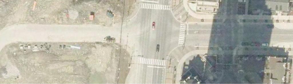
9 DRAINAGE AND STORMWATER MANAGEMENT REPORT Introduction June 19, INTRODUCTION Stantec Consulting Ltd. (Stantec) has been retained by the City of Mississauga (City) to complete a Class Environmental Assessment (Class EA) Schedule C and preliminary design for the extension of Square One Drive in Mississauga from Confederation Parkway west to Rathburn Road West. The project study area (hereafter the Site ) covers a road distance of approximately 250 m including the intersection of Square One Drive with Confederation Parkway and the proposed roundabout at Square One Drive and Rathburn Road West. The proposed extension will be a two-lane local road with a road width of approximately 9 m in addition to a boulevard and concrete sidewalk to the south and a boulevard and multi-use trail to the north. In addition to the works within the proposed Square One Drive Extension corridor, Rathburn Road West will be realigned from Confederation Parkway to near Hazineh Court to accommodate the proposed roundabout. This Drainage and Stormwater Management (SWM) Report has been prepared to document the existing drainage, water quantity and quality conditions in the study area, evaluate the relative impacts of the preferred design on the receiving surface water systems, and recommend measures to mitigate the potential impacts. The following materials were reviewed in the preparation of this report: Geotechnical Investigation, proposed Square One Drive Extension, City of Mississauga, On, prepared by GeoPro Consulting Limited, March 23, 2017 [Geotechnical Report]; City of Mississauga Development Requirements, City of Mississauga, September 2016 [City Design Manual]; Credit Valley Conservation Stormwater Management Criteria, Credit Valley Conservation Authority, 2012 [CVC SWM Criteria]; Appendix B, Landscape Design Guide for Low Impact Development, prepared by Credit Valley Conservation Authority (CVC), 2012 [CVC LID Guidelines]; Low Impact Development Stormwater Management Planning and Design Guide, prepared by CVC and Toronto and Region Conservation Authority (TRCA), 2010 [LID Guidelines]; Functional Servicing Report, City Centre Lands, City of Misusages, Sernas Associates, May 2004; and High-Rise Apartment Condominium Site Plan, Rathburn Road and Confederation Parkway, City of Mississauga, Stormwater Management Report, The Conservatory Group, July mm v:\01650\active\ square_one_drive\21_drainage_stormwater_water_resources\swm report _ \ _swm_rpt_ docx 1
10 DRAINAGE AND STORMWATER MANAGEMENT REPORT Existing Conditions June 19, EXISTING CONDITIONS 2.1 GENERAL Square One Drive is a minor collector road running northeast/southwest in the central portion of the City of Mississauga (Ward 4). The proposed extension of Square One Drive travels through mostly undeveloped land southwest of a condominium complex at 330/350 Rathburn Road. Near the west end of the Site, the proposed extension passes through Zonta Meadows Park. Near the southern edge of the right of way (ROW) for the proposed extension there is an existing Enersource building. The proposed extension is 23.5 m wide and approximately 250 m in length and captures runoff from some additional areas where it intersects with Rathburn Road West for a total area of approximately 0.71 ha. The Site falls within the Mary Fix Creek Subwatershed of the Credit River and is under the jurisdiction of the Credit Valley Conservation Authority (CVC). SWM criteria for this project have been derived from the requirements of the CVC and the City of Mississauga. The section of Rathburn Road West that is to be realigned is a four-lane road with sidewalks on both sides, a bicycle path to the south, a grassed boulevard to the north, and a grassed boulevard to the south in some sections. This section of Rathburn Road West, including both the current and the realigned road, paths, and boulevards has a total area of 1.98 ha. 2.2 EXISTING DRAINAGE Under existing conditions, the Site generally drains from northeast to southwest. Stormwater flows overland through parkland and enters catch basins (CB) before flowing through storm sewers to a 1500 mm x 3000 mm concrete box culvert approximately 150 m to the southwest. Drainage from the Rathburn Road West is picked up by CBs in the road and is conveyed to the to the same 1500 mm x 3000 mm concrete box culvert near Schneider Court. Existing drainage patterns were studied using orthoimagery of the Site and the following drawings and design sheets provided by the City of Mississauga (see Appendix A): Drawing no. G-38, Underground Services Storm Drainage, prepared by G.M. Sernas, 1992 [Rathburn Drainage Plan]; Square One Drive, Drawing no P01 prepared by AECOM, January 2007; Rathburn Road W., Drawing P-3, prepared by G.M. Sernas, 1986; and Storm Drainage Design Chart, The Woods North, by G.M. Sernas, The existing drainage pattern is identified in the existing condition plan (Figure 1). 2.3 SOILS A geotechnical investigation was conducted to obtain information on the existing subsurface conditions by means of five boreholes. Results show that the existing soil is predominantly clayey mm v:\01650\active\ square_one_drive\21_drainage_stormwater_water_resources\swm report _ \ _swm_rpt_ docx 2
11 DRAINAGE AND STORMWATER MANAGEMENT REPORT Existing Conditions June 19, 2017 silt till (HSG type D). Sandy silt was encountered below a depth of 1.4 m at borehole no. 5. The boreholes were between 1.7 to 2.0 m deep due to spoon refusal on probable shale bedrock. Groundwater was encountered at a depth of 0.6 m and 0.9 m below ground surface at boreholes BH3 and BH4, respectively. These two boreholes are located within the proposed road right of way. The other three boreholes, which are located at both ends of the proposed road, were dry upon completion of drilling. mm v:\01650\active\ square_one_drive\21_drainage_stormwater_water_resources\swm report _ \ _swm_rpt_ docx 3
12 DRAINAGE AND STORMWATER MANAGEMENT REPORT Stormwater Management Criteria June 19, STORMWATER MANAGEMENT CRITERIA Additional stormwater runoff from new pavement can impact receiving watercourses and cause flooding, erosion, and water quality impacts. Quantity and quality control measures to treat runoff should be considered for all new impervious areas and, where possible, existing surfaces. The following applicable SWM criteria are based on the City Design Manual and CVC SWM Criteria: Quantity Control: The 10-year post development flow must be controlled to the 2-year pre-development peak (City Design Manual Table, c); Quality Control: Implement Enhanced Level (80 % Total Suspended Solids (TSS) Removal) water quality control for all new developments; Water Balance: The CVC SWM Criteria Table 2-2 requires providing a minimum postdevelopment recharge of the first 3 mm for any precipitation event. The subject Site is considered a Low Volume Groundwater Recharge Areas (LGRA), which does not impact a sensitive ecological feature, or require a subwatershed study, or EIR. A 3 mm per precipitation event must be captured and infiltrated; Erosion and Sediment Control: CVC Section 4.2 requires on-site detention of 5 mm as a minimum for this Site where conditions do not warrant the detailed analyses; and Conveyance: The storm sewer system should be designed to capture and convey runoff generated by the 10-year storm event. The minimum initial time of concentration is to be 15 minutes (City of Mississauga). mm v:\01650\active\ square_one_drive\21_drainage_stormwater_water_resources\swm report _ \ _swm_rpt_ docx 4
13 DRAINAGE AND STORMWATER MANAGEMENT REPORT Square One Drive Extension Proposed Conditions June 19, SQUARE ONE DRIVE EXTENSION PROPOSED CONDITIONS 4.1 SWM PLAN The proposed extension will be a two-lane local road with a maximum pavement width of approximately 9 m (including on-street parking) in addition to a boulevard and concrete sidewalk to the south and a boulevard and multi-use trail to the north. The proposed work will increase the imperviousness within the right-of-way due to a change from grass to asphalt/concrete. A wide range of best management practices (BMPs) are available to mitigate the impacts of the increased imperviousness of the proposed road. The SWM Plan will review and evaluate the available SWM alternatives and will develop a recommendation of the suitable SWM practices based on the capital cost, level of treatment, maintenance requirements, space constraints and site-specific conditions. A preliminary design will be provided for the preferred alternative to satisfy the SWM criteria as stated in Section Low Impact Development (LID) LID is a SWM strategy that seeks to mitigate the impacts of increased runoff and stormwater pollution by managing runoff as close to its source as possible. LID comprises a set of site design strategies that minimize runoff and distributed, small scale structural practices that mimic natural or predevelopment hydrology through the processes of infiltration, evapotranspiration, harvesting, filtration and detention of stormwater. To protect the health of the Credit River watershed, the updated water management strategy calls for an immediate shift to more proactive and innovative stormwater management systems that include LID practices. Studies show that implementing LID practices can have multiple positive environmental effects which help to mitigate potential negative impacts of climate change on groundwater levels, risk of flooding and stream channel erosion. Therefore, evaluation of the available SWM measures for the subject Site will include different types of the source treatment LID options as described below. Feasible LID measures will be implemented in the proposed SWM plan Available Measures The available measures are generally classified into source, conveyance and end-of-pipe treatment alternatives. Source Treatment Alternatives: This alternative includes measures that treat precipitation where it falls, typically through infiltration or water reuse. Suitable source treatment for roads includes permeable pavement and engineered soil cells. Permeable pavement is generally not appropriate for this type of urban road due to concerns regarding maintenance requirements to prevent clogging of the permeable pathways through the pavement and due to potential groundwater contamination. mm v:\01650\active\ square_one_drive\21_drainage_stormwater_water_resources\swm report _ \ _swm_rpt_ docx 5
14 DRAINAGE AND STORMWATER MANAGEMENT REPORT Square One Drive Extension Proposed Conditions June 19, 2017 Engineered soil cells, such as Silva Cells are modular support systems that provide a sturdy and permeable ground level decking that transfers surface loads to a compacted subbase m below grade without compacting the near-surface soil layers. Because the near-surface layers remain uncompacted, void ratios remain high making the near surface layers useful for stormwater detention and infiltration. Engineered soil cells also provide suitable soil conditions for large tree growth. Engineered soil cells are recommended to provide water balance and erosion and sediment control for the proposed road. Conveyance Treatment Alternatives: This alternative includes measures which treat runoff as it flows from the source to the receiving watercourse. Conveyance treatment for roads includes enhanced roadside swales, dry grassed swales, pervious pipe and CB SHIELDS. Enhanced roadside swales should have a wide flat bottom that acts to slow and infiltrate road runoff. The established vegetation will further slow the flow and traps pollutants through filtering and nutrients uptake. Due to site constraints, no opportunities exist for a grassed swale. Dry grassed swales with check dams on shallow grades can be effective in providing detention of stormwater and infiltration where soils permit. The boulevard areas adjacent to the road could be graded as shallow dry swales to detain and infiltrate the relatively clean water from the sidewalk. Since the native soil is predominantly clay, no opportunities exist for a dry grassed swale. Pervious pipe systems are another conveyance control measure. The expected traffic volume indicates that extensive pre-treatment would be required to prevent clogging of the system with fine particles and to prevent ground water contamination. Also, clay is the predominant soil in this Site, which limits the potential effectiveness of this alternative. Therefore, pervious pipe system is not a recommended alternative for this site. CB Shields are devices that encourage sedimentation and reduce scour by intercepting influent stormwater and deflecting it toward the side of the CB. On their own, CB SHIELDS have been demonstrated to provide 50-80% TSS removal. CB SHIELDS are recommended as part of a quality control treatment train. End-of-pipe Treatment Alternatives: This alternative includes wet ponds, Oil-Grit Separators (OGS) and stormwater filter devices like Jellyfish Filters. Wet Ponds have been applied extensively for road works where the contributory drainage area exceeds 5.0 ha. Since the proposed site area is only 0.71 ha, which is less than the minimum requirement, wet ponds will not be used. OGS units are generally applied to road drainage systems, either on their own or as part of a treatment train. OGS units provides treatment through sedimentation and oilgrit capture. The Jellyfish Filter is a proprietary filtration system currently undergoing mm v:\01650\active\ square_one_drive\21_drainage_stormwater_water_resources\swm report _ \ _swm_rpt_ docx 6
15 DRAINAGE AND STORMWATER MANAGEMENT REPORT Square One Drive Extension Proposed Conditions June 19, 2017 evaluation by the Ontario Ministry of the Environment and Climate Change (MOECC). Through a combination of filtration, sedimentation and oil-grit capture, the Jellyfish Filter can be sized to provide >80% TSS removal. This system would be installed at the downstream end of the Site s storm sewer line either in a manhole or an underground vault structure. It requires removal of collected contaminants and filter washing a minimum of once per year and filter replacement every 2-5 years. Both OGS and Jellyfish Filters are suitable for this Site. 4.2 QUANTITY CONTROL Because the Site lies within the Mary Fix Creek Subwatershed, it is required that the 10-year post development flow is controlled to the 2-year pre-development peak (City Design Manual, Table c). Under existing conditions the Site has a weighted runoff coefficient of The time of concentration has been found to be 11 minutes using the Bransby-Williams method and 14 minutes using the Uplands method; therefore, the City minimum of 15 minutes has been used. yielding a 2-year pre-development peak flow from the Site is m 3 /s (see Appendix D). Under post-development conditions, the Site will have a runoff coefficient of 0.90 and a time of concentration of 15 minutes yielding a 10-year post-development runoff rate is m 3 /s. Using an 80 mm orifice tube at the downstream end of the Site to connect the proposed storm sewers to MH50, and assuming that the system backs up to the top of lowest CB during the 10- year event (DCB 17), the discharge rate from the Site is m 3 /s. Using the modified rational method, 135 m 3 of detention storage is required upstream of the orifice tube. Several methods of quantity storage that may be appropriate for this Site are discussed below Underground Tank An stormwater detention tank could be used to provide the required 141 m 3 of storage. In order to make full use of an underground tank, the top of the tank must be below the lowest CB in the system to prevent stormwater from spilling out of the CB. As such, any such system should be provided near the west end of the Site so that the tank can be installed at a minimum depth. Tank materials and styles that could be considered include: Concrete box tanks (e.g., StormTrap ); Plastic arch tanks (e.g., StormTech ); and Large-diameter HDPE pipe tank (e.g., Weholite). mm v:\01650\active\ square_one_drive\21_drainage_stormwater_water_resources\swm report _ \ _swm_rpt_ docx 7
16 DRAINAGE AND STORMWATER MANAGEMENT REPORT Square One Drive Extension Proposed Conditions June 19, Superpipe The required storage could be provided through the use of oversized conveyance pipes. The total length of proposed storm sewer pipe on the site is 190 m. The pipes would, therefore need to be approximately 1050 mm ø which is much larger than required for the conveyance of stormwater from the site. Oversizing pipes to this extent is generally much more expensive than providing the same volume in an underground tank and is not recommended for this Site Engineered Soil Cells Engineered soil cells can serve multiple purposes including stormwater detention, retention, and quality improvement. Engineered soil cells can provide significant detention volumes in the void spaces within the soil. These systems can be designed to accept stormwater directly from CBs. Section of the City Design Manual states that: With respect to optimizing the infrastructure if site grading and configuration allow, there may be the potential to replicate the stormwater quantity control storage typically provided by way of superpipes within the low impact development measures. If this is the case, the City would consider a volumetric credit if: Engineering design demonstrates technical adequacy and sufficient storage such that pipe or surface storage are redundant, and; A stormwater charge credit application is submitted which obliges the site tenant or property manager to maintain the infrastructure and also allows the City ability to inspect and enforce should there be any concerns particularly since the credit discussed here links back to flood resiliency. Subject to approval by the City, the use of engineered soil cells (e.g., Silva Cells ) could be used to achieve the detention storage required for flow attenuation Recommended Design It is recommended that the required stormwater detention volume be provided primarily through an underground storage tank. As an example, a Weholite storage system (HDPE pipe tank) has been sized for this application. The tank would be approximately 2440 mm in diameter and 29 m long(see Appendix D for preliminary design report). It is proposed that this unit be located near the proposed roundabout (see Figure 2). The size of the tank may be reduced through the use of engineered soil cells. It is recommended that this option be explored further with the City during detailed design. At that point it will be important to establish with the City the detention storage volume per m 3 of soil that will be accepted for quantity control. mm v:\01650\active\ square_one_drive\21_drainage_stormwater_water_resources\swm report _ \ _swm_rpt_ docx 8
17 DRAINAGE AND STORMWATER MANAGEMENT REPORT Square One Drive Extension Proposed Conditions June 19, QUALITY CONTROL The study area currently does not include any water quality control measures to treat runoff before discharging into the storm sewer. The SWM criteria require the implementation of enhanced level water quality control (80% TSS removal) for all new developments. CVC is adopting the City of Toronto Guidelines for OGS application. Essentially, OGS is recommended as a pre-treatment device or may be used as part of a multi-component (treatment train) approach to achieve Enhanced quality control. According to the City of Toronto Guidelines, OGS devices, operating alone at their original design capacities, are capable of achieving a TSS removal efficiency of 50%. The proposed Square One Drive Extension is located within a completely urbanized area; with limited opportunities of SWM practices that can be applied to achieve the required 80% TSS removal. Two design alternatives have been proposed. The first consists of an OGS installed at the outlet of the Site s storm sewer piping along with CB Shield on each CB. The second employs an inline filter unit installed at the outlet of the Site s storm sewer piping to meet the quality criterion. For both alternatives, the proposed Silva Cells will provide further treatment and enhance the performance of the proposed treatment train Alternative 1: CB Shields and Oil-Grit Separator An OGS unit would be located at the downstream end of the Site s storm sewer line and sized to provide 50% TSS removal. Additional treatment would be provided at each CB through the use of CB Shield devices, which will provide 50-80% TSS removal. As an example, PCSWMM for Stormceptor software was used to size a Stormceptor OGS unit, Table 1 below provides summary of the required OGS characteristics (see Appendix A for a full Stormceptor report). The combined TSS removal for the treatment train should exceed the Enhanced Level of target of 80%. Area (ha) Table 1: Proposed OGS Characteristics Imp. (%) Required TSS Removal (%) Required Annual Runoff Volume (%) % 75% Alternative 2: Jellyfish Filter An inline filter unit would be located at the downstream end of the Site s storm sewer line and sized to provide 80% TSS removal. As an example, a Jellyfish Filter unit has been sized for the Site. Table 2 below provides summary of the proposed Jellyfish characteristics. A detailed Jellyfish sizing report is included in Appendix A. mm v:\01650\active\ square_one_drive\21_drainage_stormwater_water_resources\swm report _ \ _swm_rpt_ docx 9
18 DRAINAGE AND STORMWATER MANAGEMENT REPORT Square One Drive Extension Proposed Conditions June 19, 2017 Area (ha) Table 2: Proposed Jellyfish Filter Characteristics Imp. (%) JF Type TSS Removal (%) Annual Runoff Volume (%) % JF % WATER BALANCE The CVC categorizes the Site area as being a Low Volume Groundwater Recharge Area and, therefore, requires a minimum of 3 mm per storm event to be captured and infiltrated. The Site includes approximately 0.71 ha of paved roadway which is unsuitable for infiltration without pretreatment. Soil Investigation results show that the existing soil is predominantly clayey silt till. Groundwater was encountered at a depth of 0.6 m and 0.9 m below ground surface at the two boreholes within the roadway area. Since the quality treatment of the runoff from the roadway will be accomplished with an inline treatment device installed in the storm sewer at the downstream end of the site, and due to the low permeability of the native soil and high ground water, infiltrating runoff from the road on-site is not feasible. 4.5 EROSION AND SEDIMENT CONTROL CVC requires on-site detention of 5 mm as a minimum for this Site where conditions do not warrant the detailed analyses. The peak flow generated by the 5 mm storm event over the 0.71 ha drainage area was calculated as 0.01 m 3 /s using PCSWMM software. The minimum allowable orifice size of 75 mm will release 0.02 m 3 /s, which exceeds the peak flow generated by the 5-mm storm event. Accordingly, 5 mm storage detention cannot be met by controlling the outflow from the road areas. Therefore, technologies such as Silva Cells should be considered during detailed design to achieve the erosion and sediment control targets by retaining and consuming the runoff generated by the 5-mm storm event through evapotranspiration (ET). As an example of how Silva Cells could be implemented for this Site, retention of an equivalent of 5 mm rainfall event could be provided using Silva Cells installed in the southern boulevard. A minimum of six trees would be planted along the southern boulevard. The total volume of planting soil is 90 m 3, which would provide a storage volume of 36 m 3, assuming 0.40 void ratio. The proposed Silva Cell system would capture and retain the first 12.5 mm of precipitation falling over the southern half of the roadway, which is equivalent to 5 mm over the total site area (0.71 ha). Example Erosion and Sediment Control Calculations are included in Appendix B. mm v:\01650\active\ square_one_drive\21_drainage_stormwater_water_resources\swm report _ \ _swm_rpt_ docx 10
19 DRAINAGE AND STORMWATER MANAGEMENT REPORT Rathburn Road West Proposed Conditions June 19, RATHBURN ROAD WEST PROPOSED CONDITIONS The proposed realignment of Rathburn Road West shifts the roadway south by a maximum of approximately 7 m. The width of the realigned roadway will be approximately the same as that of the current roadway. Landscaped areas south of the existing roadway that will be converted to paved lanes in the proposed condition will be offset by increases in landscaped areas north of the realigned roadway. As such, the imperviousness and existing drainage patterns in and around Rathburn Road West will be generally maintained under the proposed conditions. 5.1 QUANTITY CONTROL The imperviousness and drainage area of the realigned Rathburn Road West will remain unchanged in the proposed condition; therefore, no quantity controls have been proposed. 5.2 QUALITY CONTROL According to the Rathburn Drainage Plan, under existing conditions, the storm sewer under Rathburn Road West immediately east (downstream) of the intersection with the Square One Drive Extension receives drainage from 9.2 ha. The area of Rathburn Road West that is being realigned totals 1.98 ha. Since the storm sewer in this area conveys flows from a significantly larger area than is being realigned, it is not feasible to provide centralized quality treatment on the storm sewer under Rathburn Road West. It is proposed that CB Shield devices be installed on all catch basins of the realigned road to provide 50-80% TSS removal. 5.3 WATER BALANCE The imperviousness and drainage area of the realigned Rathburn Road West will remain unchanged in the proposed condition; therefore, no water balance controls have been proposed. 5.4 EROSION AND SEDIMENT CONTROL As with the Square One Drive Extension, it is proposed that erosion and sediment control requirements for the Rathburn Road West realignment (5 mm detention) be achieved through the use of engineered soil cells. For example; minimum of 17 trees could be planted in Silva Cells along the northern boulevard. The total volume of planting soil would be 255 m 3, which would provide a storage volume of 102 m 3, assuming 0.40 void ratio. The proposed Silva Cell system would capture and retain the first 9.7 mm of precipitation falling over the northern 24 m of the 40 m road right of way, which is equivalent to 5 mm over the total Rathburn Road West right of way area (1.98 ha). Erosion and Sediment Control Calculations are included in Appendix B. mm v:\01650\active\ square_one_drive\21_drainage_stormwater_water_resources\swm report _ \ _swm_rpt_ docx 11
20 DRAINAGE AND STORMWATER MANAGEMENT REPORT Conveyance June 19, CONVEYANCE 6.1 DESIGN CRITERIA The existing drainage pattern shows that the Site drains towards the west into an existing 1500 mm x 3000 mm concrete box culvert which flows southeast. It is proposed that runoff from the Site will be conveyed via a proposed storm sewer system along Square One Drive and discharged into the 900 mm storm sewer line along Rathburn Road West. Approximately 100 m south of its intersection with Square One Drive, the 900 mm storm sewer empties into the existing 1500 mm x 3000 mm concrete box culvert. Runoff from Rathburn Road West between Confederation Drive to Hazineh Court is collected in a storm sewer under Rathburn Road which empties into a 1500 mm x 3000 mm concrete box culvert near Schneider Court. The realignment of Rathburn Road West will result in the existing storm sewer being located underneath the proposed curb. The design of the proposed storm water drainage system was based on the following design criteria, as per The City of Mississauga Guidelines: The storm sewer network should be designed with adequate capacity to accommodate runoff generated by the 10-year storm events, and 15 minutes initial time of concentration; Sewer must have an adequate gradient to maintain a velocity of 0.75 m/s minimum for circular concrete pipes and maximum velocity of 4.0 m/s; The storm sewers shall be located 1.5 m south or west of the centre line of the right of way; Maximum spacing of manholes shall be 120 m for sewers 600 mm or less in diameter and 170 m for sewers 675 mm or greater in diameter; The maximum area to be served by any catch basin shall be 2000 m 2 of paved area or 5000 m 2 of sodded area; Maximum spacing for catch basins shall be as follows: o Road 0.5% - 70 m o Road 0.5% to 3% - 90 m o Road grade greater than 3% - 70 m; Design flow calculations must be completed on City of Mississauga forms shown on City Standard Drawing No.'s and , for this purpose; and Since the future buildings in the vicinity of the Site will not discharge into the proposed road storm sewers, hence the pipes will be placed with 1.2 m cover below the centre line of the road. mm v:\01650\active\ square_one_drive\21_drainage_stormwater_water_resources\swm report _ \ _swm_rpt_ docx 12
21 DRAINAGE AND STORMWATER MANAGEMENT REPORT Conveyance June 19, MINOR FLOW Under existing conditions, the Site generally drains from northeast to southwest. Stormwater flows overland through parkland and enters CBs before flowing through storm sewers to a 1500 mm x 3000 mm concrete box culvert approximately 150 m to the southwest. Based on the Existing Underground Services, Storm Drainage drawing and storm sewer design sheets provided by the City, two alternatives were evaluated for the proposed outlet for the Square One Drive Extension. The first alternative is to outlet into the existing 900 mm storm sewer on Rathburn Road West, which is currently flowing at 87% of full flow capacity during the 10-year event. Table 3 below shows pipe capacities, existing condition and proposed condition peak flows (using a runoff coefficient of 0.90). The proposed junction point for the storm sewer from the Site is at existing MH 50 at the intersection of Rathburn Road West and Via Russo Court. It should be noted that the 10-year flow from the proposed road will be reduced by passing the flow into the proposed Silva cell tree boxes. Table 3: Storm Sewer Networks Conditions Fro m MH To MH Pipe Diameter (mm) Full Flow Capacity (m 3 /s) Drainage Area (ha) Existing Conditions m 3 /s Flow From 10 Year Event % Full With Runoff from Site Drainage Area (ha) m 3 /s % Full x 1500 (Box Culvert) The second considered alternative is to discharge into the storm sewer running along Confederation Parkway, however, the addition of the 10-year flow from the Site would result in an expected flow of 0.29 m 3 /s which exceeds the capacity of the pipe on Confederation Parkway of 0.21 m 3 /s (expected flow in this pipe under existing conditions is 0.11 m 3 /s). Therefore, Alternative 1 is recommended, and the proposed storm sewer for Square One Drive Extension is designed to discharge into the existing storm sewer along Rathburn Road West. The storm sewer design sheet is included in Appendix C. It is noted that the Storm Sewer under Rathburn Road West is flowing nearly at capacity and will likely require upsizing in the future. An assessment of the extent of the improvements required is beyond the scope of this report; however, it is recommended that the City investigate this further during detailed design. mm v:\01650\active\ square_one_drive\21_drainage_stormwater_water_resources\swm report _ \ _swm_rpt_ docx 13
22 DRAINAGE AND STORMWATER MANAGEMENT REPORT Conveyance June 19, MAJOR FLOW Under existing conditions, the Site drains overland to CBs that connect to 250 mm pipes that graduate to 300 mm pipes then feed directly into the 1500 mm x 3000 mm box culvert without using the storm sewer line running along Rathburn Road West. The proposed road slopes from a high point of at the intersection with the Confederation Parkway, to a low point of at the intersection with Rathburn Road West. Accordingly, the major flow will be conveyed via the proposed roadway as overland flow towards Rathburn Road West. The overland flow route on Rathburn Road West will be maintained. mm v:\01650\active\ square_one_drive\21_drainage_stormwater_water_resources\swm report _ \ _swm_rpt_ docx 14
23 DRAINAGE AND STORMWATER MANAGEMENT REPORT Summary June 19, SUMMARY The proposed plan meets the SWM criteria as summarized below with the exception of the detention and infiltration of precipitation falling on the paved road area. Water Quantity Control: A stormwater detention system along with an orifice tube at the downstream end of the system will reduce the 10-year post development flow rate to the 2-year pre-development flow rate. Water Quantity Control: Either an OGS in conjunction with CB Shields on all CBs or a Jellyfish will be used to achieve the quality control target of 80 % TSS removal efficiency for the developed areas. Water Balance: Due to the low permeability of the native soil and high ground water, infiltrating runoff from the road on-site is not feasible. Erosion and Sediment Control: Engineered soil cells could be used to retain (then reuse) runoff generated by the 5-mm storm event. Conveyance: Based on evaluation of the available alternatives, it is recommended to connect the proposed storm sewer into the existing stormsewer along Rathburn Road West. We trust the information provided will assist you in completing your review of the SWM plan for this study area. Should you require any additional information, please contact the undersigned. Sincerely, STANTEC CONSULTING LTD. Mustafa Mukhtar, P. Eng. Water Resources Engineer Tel : (905) mustafa.mukhtar@stantec.com Steffen Pentelow, EIT Water Resources Engineering Intern Tel : (905) steffen.pentelow@stantec.com mm v:\01650\active\ square_one_drive\21_drainage_stormwater_water_resources\swm report _ \ _swm_rpt_ docx 15


24 R 3000x1500 CONCRETE BOX CULVERT ZONTA MEADOWS PARK ELO STUDY AREA E RIV D A HBU RAT PARKSIDE VILLAGE DRIVE ST WE AD O R RN CONFEDERATIO N PARKWAY PRINCE OF WALES DRIVE ARE SQU IVE DR ONE


25 RN BU TH RA A RO T D S WE ZONTA MEADOWS PARK RA ELO VE I DR ha 4.85ha PARKSIDE VILLAGE DRIVE ha CONFEDERATIO N PARKWAY PRINCE OF WALES DRIVE SQUARE ONE DRIVE
26
27 APPENDICES
28 DRAINAGE AND STORMWATER MANAGEMENT REPORT Appendix A Quality Control April 21, 2017 QUALITY CONTROL A.1

29 STANDARD OFFLINE Jellyfish Filter Sizing Report Project Information Date Thursday, April 20, 2017 Project Name Square One Rd Ext Project Number revised area Location Mississauga Jellyfish Filter Design Overview This report provides information for the sizing and specification of the Jellyfish Filter. When designed properly in accordance to the guidelines detailed in the Jellyfish Filter Technical Manual, the Jellyfish Filter will exceed the performance and longevity of conventional horizontal bed and granular media filters. Please see for more information. Jellyfish Filter System Recommendation The Jellyfish Filter model JF6-4-1 is recommended to meet the water quality objective by treating a flow of 22.7 L/s, which meets or exceeds 90% of the average annual rainfall runoff volume based on 18 years of TORONTO CENTRAL rainfall data for this site. This model has a sediment capacity of 256 kg, which meets or exceeds the estimated average annual sediment load. Number of Number of Manhole Treatment Jellyfish Sediment High-Flo Draindown Diameter Flow Rate Model Capacity (kg) Cartridges Cartridges (m) (L/s) JF The Jellyfish Filter System The patented Jellyfish Filter is an engineered stormwater quality treatment technology featuring unique membrane filtration in a compact stand-alone treatment system that removes a high level and wide variety of stormwater pollutants. Exceptional pollutant removal is achieved at high treatment flow rates with minimal head loss and low maintenance costs. Each lightweight Jellyfish Filter cartridge contains an extraordinarily large amount of membrane surface area, resulting in superior flow capacity and pollutant removal capacity. Maintenance Regular scheduled inspections and maintenance is necessary to assure proper functioning of the Jellyfish Filter. The maintenance interval is designed to be a minimum of 12 months, but this will vary depending on site loading conditions and upstream pretreatment measures. Quarterly inspections and inspections after all storms beyond the 5-year event are recommended until enough historical performance data has been logged to comfortably initiate an alternative inspection interval. Please see for more information. Thank you for the opportunity to present this information to you and your client. CDN/Int'l: 1 (800) US: 1 (888)

30 Performance Jellyfish efficiently captures a high level of Stormwater pollutants, including: 89% of the total suspended solids (TSS) load, including particles less than 5 microns 59% TP removal & 51% TN removal 90% Total Copper, 81% Total Lead, 70% Total Zinc Particulate-bound pollutants such as nutrients, toxic metals, hydrocarbons and bacteria Free oil, Floatable trash and debris Field Proven Peformance The Jellyfish filter has been field-tested on an urban site with 25 TARP qualifying rain events and field monitored according to the TARP field test protocol, demonstrating: A median TSS removal efficiency of 89%, and a median SSC removal of 99%; The ability to capture fine particles as indicated by an effluent d50 median of 3 microns for all monitotred storm events, and a median effluent turbidity of 5 NTUs; A median Total Phosphorus removal of 59%, and a median Total Nitrogen removal of 51%. Jellyfish Filter Treatment Functions Pre-treatment and Membrane Filtration CDN/Int'l: 1 (800) US: 1 (888)
31 Project Information Date: Thursday, April 20, 2017 Project Name: Square One Rd Ext Project Number: revised area Location: Mississauga Designer Information Company: Stantec Contact: Steffen Petelow Phone #: Notes Rainfall Name: TORONTO CENTRAL State: ON ID: 100 Record: 1982 to 1999 Co-ords: 45 30'N, 90 30'W Drainage Area Total Area: 0.71 ha Imperviousness: 100% Upstream Detention Peak Release Rate: n/a Pretreatment Credit: n/a Design System Requirements Flow 90% of the Average Annual Runoff based on 18 years Loading of TORONTO CENTRAL rainfall data: Treating 90% of the average annual runoff volume, Sediment 4232 m³, with a suspended sediment concentration of Loading 60 mg/l. Recommendation 254 kg The Jellyfish Filter model JF6-4-1 is recommended to meet the water quality objective by treating a flow of 22.7 L/s, which meets or exceeds 90% of the average annual rainfall runoff volume based on 18 years of TORONTO CENTRAL rainfall data for this site. This model has a sediment capacity of 256 kg, which meets or exceeds the estimated average annual sediment load. Jellyfish Model Number of High-Flo Cartridges Number of Draindown Cartridges Manhole Diameter Wet Vol Below Deck (L) Sump Storage 19.3 L/s Oil Capacity Treatment Flow Rate (L/s) Sediment Capacity (kg) (m) (m³) (L) JF JF JF JF JF JF JF JF JF JF JF JF JF JF JF JF JF JF JF JF JF JF JF JF JF JF JF JF JF CDN/Int'l: 1 (800) US: 1 (888)
32 Jellyfish Filter Design Notes Typically the Jellyfish Filter is designed in an offline configuration, as all stormwater filter systems will perform for a longer duration between required maintenance services when designed and applied in off-line configurations. Depending on the design parameters, an optional internal bypass may be incorporated into the Jellyfish Filter, however note the inspection and maintenance frequency should be expected to increase above that of an off-line system. Speak to your local representative for more information. Jellyfish Filter Typical Layout Typically, 18 inches (457 mm) of driving head is designed into the system, calculated as the difference in elevation between the top of the diversion structure weir and the invert of the Jellyfish Filter outlet pipe. Alternative driving head values can be designed as 12 to 24 inches (305 to 610mm) depending on specific site requirements, requiring additional sizing and design assistance. Typically, the Jellyfish Filter is designed with the inlet pipe configured 6 inches (150 mm) above the outlet invert elevation. However, depending on site parameters this can vary to an optional configuration of the inlet pipe entering the unit below the outlet invert elevation. The Jellyfish Filter can accommodate multiple inlet pipes within certain restrictions. While the optional inlet below deck configuration offers 0 to 360 degree flexibility between the inlet and outlet pipe, typical systems conform to the following: Model Diameter (m) Minimum Angle Minimum Inlet Pipe Minimum Outlet Pipe Inlet / Outlet Pipes Diameter (mm) Diameter (mm) º º º º º The Jellyfish Filter can be built at all depths of cover generally associated with conventional stormwater conveyance systems. For sites that require minimal depth of cover for the stormwater infrastructure, the Jellyfish Filter can be applied in a shallow application using a hatch cover. The general minimum depth of cover is 36 inches (915 mm) from top of the underslab to outlet invert. If driving head caclulations account for water elevation during submerged conditions the Jellyfish Filter will function effectively under submerged condtions. Jellyfish Filter systems may incorporate grated inlets depending on system configuration. For sites with water quality treatment flow rates or mass loadings that exceed the design flow rate of the largest standard Jellyfish Filter manhole models, systems can be designed that hydraulically connect multiple Jellyfish Filters in series or alternatively Jellyfish Vault units can be designed. CDN/Int'l: 1 (800) US: 1 (888)

33
34
35
36
37
38
39 Stormceptor Design Summary PCSWMM for Stormceptor Project Information Date 3/30/2017 Project Name Square One Road Project Number Location Mississauga Designer Information Company Contact Notes N/A Drainage Area Stantec Mustafa Total Area (ha) 0.71 Imperviousness (%) 90 The Stormceptor System model STC 750 achieves the water quality objective removing 75% TSS for a City of Toronto (clay, silt and sand) particle size distribution and 91% runoff volume. Rainfall Name TORONTO CENTRAL State ON ID 100 Years of Records 1982 to 1999 Latitude 45 30'N Longitude 90 30'W Water Quality Objective TSS Removal (%) 50 Runoff Volume (%) 90 Upstream Storage Storage Discharge (ha-m) (L/s) 0 0 Stormceptor Sizing Summary Stormceptor Model TSS Removal Runoff Volume % % STC STC STC STC STC STC STC STC STC STC STC STC Stormceptor Design Summary - 1/2
40 Particle Size Distribution Removing silt particles from runoff ensures that the majority of the pollutants, such as hydrocarbons and heavy metals that adhere to fine particles, are not discharged into our natural water courses. The table below lists the particle size distribution used to define the annual TSS removal. City of Toronto (clay, silt and sand) Particle Size Distribution Specific Settling Specific Settling Particle Size Distribution Gravity Velocity Gravity Velocity µm % m/s µm % m/s Stormceptor Design Notes Stormceptor performance estimates are based on simulations using PCSWMM for Stormceptor version 1.0 Design estimates listed are only representative of specific project requirements based on total suspended solids (TSS) removal. Only the STC 300 is adaptable to function with a catch basin inlet and/or inline pipes. Only the Stormceptor models STC 750 to STC 6000 may accommodate multiple inlet pipes. Inlet and outlet invert elevation differences are as follows: Inlet and Outlet Pipe Invert Elevations Differences Inlet Pipe Configuration STC 300 STC 750 to STC STC 9000 to 6000 STC Single inlet pipe 75 mm 25 mm 75 mm Multiple inlet pipes 75 mm 75 mm Only one inlet pipe. Design estimates are based on stable site conditions only, after construction is completed. Design estimates assume that the storm drain is not submerged during zero flows. For submerged applications, please contact your local Stormceptor representative. Design estimates may be modified for specific spills controls. Please contact your local Stormceptor representative for further assistance. For pricing inquiries or assistance, please contact Imbrium Systems Inc., Stormceptor Design Summary - 2/2
41 80% Lab Testing Results for CB Shield - % Capture vs. Flow Rate 70% CB Shield in Place 60% No Shield - Control Run Log. (CB Shield in Place) 50% Log. (No Shield - Control Run) PERCENT CAPTURE 40% 30% 20% 10% 0% FLOW (L/S)
42
43


44 indicates in his that t
45 Average Annual Sediment Removal Rates (%) using a CB Shield (based on ETV Sediment - 1 to 1000 micron Particle Size Distribution) Area to CB (ha) Imperviousness 1 (%) 20% 35% 50% 65% 80% 100% % 57% 57% 57% 56% 56% % 56% 56% 55% 55% 54% % 55% 54% 53% 52% 51% % 53% 51% 49% 48% 46% % 50% 48% 46% 45% 43% % 48% 46% 44% 42% 40% % 47% 44% 42% 40% 38% % 45% 43% 40% 39% 36% Notes: 1. Runoff Coefficient 'C' is approximately equal to *Impervious Fraction. 2. Above chart is based on long term continuous hydrologic analysis of Toronto, Ontario (Bloor St) rainfall data. 3. Assumes 0.6 m sump in CB and that maintenance is performed (i.e. CB cleaning) when required by sediment/pollutant build-up or otherwise. 4. See accompanying chart for suggested maintenance scheduling - AND - get CB Shield Inc. to monitor it for you in field. 5. Sediment/Pollutant removal rates based on third party certified laboratory testing using ETV sediment (PSD analysis available on request). 6. See additional discussion regarding scour protection from CB Shield during more infrequent runoff events.


Shield, under urban environments.")


 Water runs down the slanted plate and over the slotted grate.")


")
 Filtering water; e) Indoor drying Chemical Total")

 Organic Content")


46 Catch Basin Shield: Localized Sediment Control in Urban Environments Pavneet Brar, Jennifer Drake, Ph.D., Stephen Braun Context Discussion Annual Sediment Retention Degradation of stormwater runoff quality has lead to implementation of Treatment Train Approach by many municipalities. Many localized controls exist, but not all are implemented, due to: Perceived additional costs Unknown maintenance and long-term functionality Lack of credible verification protocols An exploratory field study was conducted by the University of Toronto to evaluate the performance and feasibility of a catch basin insert, called Catch Basin (CB)Shield, under urban environments. Objective: Ease the transition of CB Shields from testing stage to field-implementation stage. CB Shield Source Conveyance End-of-Pipe CB Shield can simply be placed in catch basins to improve their sediment retention capability. 1) Water enters through the catch basin frame on the top. 2) Water runs down the slanted plate and over the slotted grate Methodology Two locations at the University of Toronto are tested: at each location, there is a control and a retrofitted catch basin. June to December 2015: Sumps sampled bi-weekly and tested for chemical, physical, and microbiological parameters. December 2015: Complete catch basin clean out. Once only sediment remained, they were analyzed. Retaining more sediments in the sump is beneficial for municipal infrastructure, local waterbodies, and aquatic habitats. The use of localized controls, such as CB Shield, can be encouraged by: Establishing better communication between hierarchical operational entities Having clear dissemination of maintenance requirements and practices Promoting best management practices and novel technologies through pilot field testing Conventional Catch basin with CB Shield a) b) c) d) e) Catch basin disturbed during study; accidently cleaned out early by UofT Facilities Services a) Cleanout using trashpump; b) Pail-and-shovel method for sediment; c) Rooftop drying; d) Filtering water; e) Indoor drying Chemical Total Nitrogen (TKN) Total Phosphorus (TP) Metals scan (Arsenic, Cadmium, Chromium, Copper, Lead, Manganese, Nickel, Selenium, Silver, and Zinc) a) b) c) d) e) Physical Dry weight Particle Size Distribution (Fine: <53μm, Medium: 53μm -2mm, Coarse: 2-4mm) Organic Content Location 1: Sandford Fleming (SF) Building Catch basin not properly cleaned prior to study; older sediment deposited below 11 depth Dried sediment weight (kg) captured in the sumps Location 2: Graduate Student Union (GSU) Building Control Shielded Control Shielded Volume (%) of the sump filled by sediment Weight (g) of total Nutrients captured (F = fine, M = medium, and C = coarse) F M C F M C TKN TP Weight (g) of total Heavy Metals captured F M C F M C TKN TP F M C F M C TKN TP 3) The sump is not turbulent, so sediments and other material are able to settle out. a) Weigh dry sediment; b) Particle size distribution using sieves; c) Samples for chemical analysis; d) Organic content using ignition; e) Dried sediment for SF shielded, GSU control, and GSU shielded, respectively F M C F M C F M C Cu Pb Zn F M C F M C F M C Cu Pb Zn F M C F M C F M C Cu Pb Zn
47 DRAINAGE AND STORMWATER MANAGEMENT REPORT Appendix B Erosion and Sediment Control April 21, 2017 EROSION AND SEDIMENT CONTROL B.2
48 Erosion Control Project Name :Square One Missussaga Project No. : Runoff from the south portion of the roadway will be captured via catchbasins which drain into the Silva Cells soil. April 24, 2017 Total Site Area 0.71 ha Targe Volume (based on retention of 5 mm over site area) 36 m 3 Available Retention Volume: Total no. of trees within the boulevard 6 tree Volume of planting soil per tree 15 m 3 Total volume of planting soil 90 m 3 Void ratio 0.4 Total void volume 36 m 3 Captured Rainwater Volume Half Road Width 11.5 m Total length of boulevard + sidewalk 250 m Total Area 2,875 m 2 Capture event 12.5 mm Total rain volume captured by the trees 36 m 3 Target volume 36 m 3 % of target 101% Ok
49 Erosion Control: Rathburn Road West Project Name :Square One Missussaga Project No. : Runoff from the north portion of the roadway will be captured via catchbasins which drain into the Silva Cells soil. June 19, 2017 Total Site Area 1.98 ha Targe Volume (based on retention of 5 mm over site area) 99 m 3 Available Retention Volume: Total no. of trees within the boulevard 17 trees Volume of planting soil per tree 15 m 3 Total volume of planting soil 255 m 3 Void ratio 0.4 Total void volume 102 m 3 Captured Rainwater Volume Total ROW Width 40 m Captured ROW Width 24 m Total length of boulevard + sidewalk 425 m Total Area 10,158 m 2 Capture event 9.7 mm Total rain volume captured by the trees 99 m 3 Target volume 99 m 3 % of target 100% Ok
50 Erosion Control Project Name :Square One Missussaga Project No. April 24, 2017 CVC requires on-site detention of 5 mm to satisfy the erosion and sediment control requiremets The peak flow generated by the 5 mm storm event over the 0.71 ha drainage area was calculated as 0.01 m3/s using PCSWMM software. The minimum allowable orifice size of 75 mm will release 0.02 m 3 /s, which exceeds the peak flow generated by the 5-mm storm event Accordingly, 5 mm storage detention cannot be met by controlling the outflow from the road areas. PCSWMM Model Rainfall and Runoff Graphs Rainfall Runoff
51 PCSWMM Report EPA STORM WATER MANAGEMENT MODEL - VERSION 5.1 (Build ) Square One Dr Extension WARNING 01: wet weather time step reduced to recording interval for Rain Gage 5mm ********************************************************* NOTE: The summary statistics displayed in this report are based on results found at every computational time step, not just on results from each reporting time step. ********************************************************* **************** Analysis Options **************** Flow Units... CMS Process Models: Rainfall/Runoff... YES RDII... NO Snowmelt... NO Groundwater... NO Flow Routing... NO Water Quality... NO Infiltration Method... CURVE_NUMBER Starting Date... AUG :00:00 Ending Date... AUG :00:00 Antecedent Dry Days Report Time Step... 00:01:00 Wet Time Step... 00:01:00 Dry Time Step... 00:05:00 ************************** Volume Depth Runoff Quantity Continuity hectare-m mm ************************** Total Precipitation Evaporation Loss Infiltration Loss Surface Runoff Final Storage Continuity Error (%) ************************** Volume Volume Flow Routing Continuity hectare-m 10^6 ltr **************************
52 Dry Weather Inflow Wet Weather Inflow Groundwater Inflow RDII Inflow External Inflow External Outflow Flooding Loss Evaporation Loss Exfiltration Loss Initial Stored Volume Final Stored Volume Continuity Error (%) *************************** Subcatchment Runoff Summary *************************** Total Total Total Total Total Total Peak Runoff Precip Runon Evap Infil Runoff Runoff Runoff Coeff Subcatchment mm mm mm mm mm 10^6 ltr CMS C


53 Stormwater and the Silva Cell System SCHEMATICS Raingarden Schematic - Section View Plan View Rainleader Schematic - Section View Plan View Catch Basin Schematic - Section View Plan View Curb Cut Schematic - Section View Plan View Updated 2/15/2011

54 Drawing is for schematic purposes only. Project designer must determine Silva Cell system and pipe sizing, location, overflow design, and slopes to meet project requirements. Stormwater shall be pre-treated as needed prior to distribution through the Silva Cell system. Please refer to the Silva Cell standard details and specifications for more information. RAINGARDEN BUILDING STREET Pipe cleanout and monitoring well in gap between Silva Cells Perforated Distribu on Pipe within Cell frames. Pipe level set for ow through or reten on per project. Surge basin collects runo and dissipates energy, stormwater over ows into raingarden Silva Cell system - see standard details and speci ca ons Emergency over ow. Pipe level set for ow through or reten on per project. Stormwater and the Silva Cell System Raingarden Schematic Updated 2/15/2011


55 Drawing is for schematic purposes only. Project designer must determine Silva Cell system and pipe sizing, location, overflow design, and slopes to meet project requirements. Stormwater shall be pre-treated as needed prior to distribution through the Silva Cell system. Please refer to the Silva Cell standard details and specifications for more information. BUILDING Perforated Distribu on Pipe within Cell frames. Pipe level set for ow through or reten on per project. Silva Cell system - see standard details and speci ca ons Pipe cleanout and monitoring well RAINGARDEN STREET Surge basin collects runo and dissipates energy, stormwater over ows into raingarden SECTION Emergency over ow. Pipe level set for ow through or reten on per project. Updated 2/15/2011 Stormwater and the Silva Cell System Raingarden Schematic


56 Drawing is for schematic purposes only. Project designer must determine Silva Cell system and pipe sizing, location, overflow design, and slopes to meet project requirements. Stormwater shall be pre-treated as needed prior to distribution through the Silva Cell system. Please refer to the Silva Cell standard details and specifications for more information. Standard Rainleader diverted into Silva Cell system Silva Cell system - see standard details and speci ca ons Perforated Distribu on Pipe within Cell frames. Pipe level set for ow through or reten on per project. STREET Emergency Rainleader bypasses Silva Cell system BUILDING Stormwater and the Silva Cell System Rainleader Schematic Updated 2/15/2011


57 Drawing is for schematic purposes only. Project designer must determine Silva Cell system and pipe sizing, location, overflow design, and slopes to meet project requirements. Stormwater shall be pre-treated as needed prior to distribution through the Silva Cell system. Please refer to the Silva Cell standard details and specifications for more information. Silva Cell system - see standard details and speci ca ons BUILDING Standard Rainleader diverted into Silva Cell system Emergency Rainleader bypasses Silva Cell system Perforated Distribu on Pipe within Cell frames. Pipe level set for ow through or reten on per project. STREET SECTION Updated 2/15/2011 Stormwater and the Silva Cell System Rainleader Schematic


58 Drawing is for schematic purposes only. Project designer must determine Silva Cell system and pipe sizing, location, overflow design, and slopes to meet project requirements. Stormwater shall be pre-treated as needed prior to distribution through the Silva Cell system. BUILDING Please refer to the Silva Cell standard details and specifications for more information. STREET Pipe cleanout and monitoring well in gap between Silva Cells Perforated Distribu on Pipe within Cell frames. Pipe level set for ow through or reten on per project. Silva Cell system - see standard details and speci ca ons Catch Basin - slows ow, collects debris BUILDING Perforated Distribu on Pipe within Cell frames. Pipe level set for ow through or reten on per project. Pipe cleanout and monitoring well in gap between Silva Cells Silva Cell system - see standard details and speci ca ons Catch Basin - slows ow, collects debris Stormwater and the Silva Cell System Catch Basin Schematic Updated 2/15/2011


59 Drawing is for schematic purposes only. Project designer must determine Silva Cell system and pipe sizing, location, overflow design, and slopes to meet project requirements. Stormwater shall be pre-treated as needed prior to distribution through the Silva Cell system. Please refer to the Silva Cell standard details and specifications for more information. BUILDING Pipe cleanout and monitoring well Perforated Distribu on Pipe within Cell frames. Pipe level set for ow through or reten on per project. Silva Cell system - see standard details and speci ca ons SECTION 2 STREET SECTION Catch Basin - slows ow, removes debris Emergency over ow. Pipe level set for ow through or reten on per project. Updated 2/15/2011 Stormwater and the Silva Cell System Catch Basin Schematic
60 Drawing is for schematic purposes only. Project designer must determine Silva Cell system and pipe sizing, location, overflow design, and slopes to meet project requirements. Stormwater shall be pre-treated as needed prior to distribution through the Silva Cell system. Please refer to the Silva Cell standard details and specifications for more information. BUILDING Curb cut with splash pad or apron STREET Silva Cell system - see standard details and speci ca ons Stormwater and the Silva Cell System Curb Cut Schematic Updated 2/15/2011


61 Drawing is for schematic purposes only. Project designer must determine Silva Cell system and pipe sizing, location, overflow design, and slopes to meet project requirements. Stormwater shall be pre-treated as needed prior to distribution through the Silva Cell system. Please refer to the Silva Cell standard details and specifications for more information. BUILDING Silva Cell system - see standard details and speci ca ons Curb cut with splash pad or apron to dissipate energy STREET SECTION Updated 2/15/2011 Stormwater and the Silva Cell System Curb Cut Schematic
62 DRAINAGE AND STORMWATER MANAGEMENT REPORT Appendix C Stormsewer Design Sheet April 21, 2017 STORMSEWER DESIGN SHEET C.3
63 Storm Sewer Design Sheet Rainfall Intensity = A City of Mississauga (Tc+B)^c 10-YEAR 100-YEAR Project: Square One Drive Extension A= Project No: B= Date: 21-Apr-17 c= Designed by: SP Starting Tc = 15 min 10-YR 10-YR 10-YR 10-YR 10-YR 10-YR Location of Secion FROM TO AREA RUNOFF "AR" ACCUM. RAINFALL ACCUM. LENGTH SLOPE PIPE FULL FLOW FULL FLOW TIME OF ACC. TIME OF MH MH COEFFICIENT "AR" INTENSITY FLOW DIAMETER CAPACITY VELOCITY CONCENTRATION CONC. (ha) "R" (mm/hr) (m 3 /s) (m) (%) (mm) (m3/s) (m/s) (min) (min) Square One Square One
64 DRAINAGE AND STORMWATER MANAGEMENT REPORT Appendix D Quantity Control June 19, 2017 QUANTITY CONTROL D.1
65 Project: Square One Drive Extension Project Number: Project Location: Mississauga, ON Date: 6/19/2017 Pre-Development 2-year Peak Flow Storm A B C 2-year Area Impervious Pervious Total/Weighted Runoff Coefficient C Time of concentration 15.0 minutes Rainfall Intensity 60 mm/hr Rational Method = 2.78 C = Runoff Coefficient i = Rainfall Intensity (mm/hr) A = Contributing Area (ha) Q = Flow (m 3 /s) Target Flow = m 3 /s (Existing conditions 2-year peak flow) Post Development Conditions Orifice Control: Orifice Equation: Q = C d A(2gh) 1/2 C d 0.82 (Orifice tube) Location MH50 Lowest CB Elevation m Orifice Size 80 mm Orifice Invert m Centroid m Obvert m Head 4.41 m
66 Flow Area m 2 Proposed Release Rate 38 L/s Modified Rational Method Storage Calculation Storm A B C 10-year Area = 0.71 ha Runoff Coefficient = 0.90 Time of Conc = 15.0 min Time Increment = 5.0 min Design Release Rate = m 3 /s Maximum Storage = 135 m 3 Time (min) Rainfall Intensity (mm/hr) Storm Runoff (m 3 /s) Runoff Volume (m 3 ) Volume Released (m 3 ) Storage Required (m 3 )

67 Weholite LIGHTWEIGHT PIPE SYSTEM

68 The lightweight pipe that takes a heavier load Weholite pipe is large diameter, profile wall pipe made from highdensity polyethylene (HDPE) resin, which is manufactured to ASTM F-894. Designed for gravity and low-pressure applications, Weholite s raw material properties have been combined with patented structural wall technology to create a lightweight engineered pipe with superior loading capacity. Lighter. Stronger. Chemical Resistant. Weholite pipe is much lighter than similarly sized concrete pipe. Combine this with longer manufacturing lengths and Weholite allows you to achieve savings in labour and equipment Weholite HDPE pipe will not corrode, tuberculate or support biological growth, making it the material of choice in wastewater and harsh chemical environments. It is inert to salt water and the chemicals likely to be present in sanitary sewage effluent. Like all HDPE pipe, Weholite has a smooth ID that maintains its flow capability over time. The low Manning s roughness factor of 0.01 remains constant, even after years of use. Easier to Transport. Easier to Install. Reliable Joints. Weholite pipe is much easier to handle and install than heavier, rigid concrete or metallic pipe. This means potential cost savings during the construction process. Weholite offers a variety of joining methods that meet or exceed your project's tightness requirements. Field fusion welding, Weholite Coupling Bands and Threaded Joints each meet the unique demands for the wide range of applications for which they are designed. 2


69 Cost Effective. Permanent. Weholite pipe offers distinct chemical and physical advantages over FRP, concrete and cast or ductile iron pipe. It can be field bent to a radius 200 times the nominal pipe diameter eliminating many fittings required for directional changes in piping systems made from other materials. In addition, the flexibility of Weholite pipe makes it well suited for dynamic soils and areas prone to earthquakes. Weholite is cost effective in both the short and long term. The fact that it is lightweight makes it easier to transport and install. The fact that it utilizes reliable joining methods means years of maintenance free use. The Plastics Pipe Institute conservatively estimates the service life for HDPE pipe to be years. The Weholite Advantage Lightweight Impact Resistant Corrosion Resistant Chemical Resistant Fatigue Resistant Reliable Joints Flexible Long Life Environmentally Friendly 3


70 Proven performance in many applications Since its development, large diameter HDPE pipe has been used successfully in thousands of installations world-wide. Weholite has proven itself in both municipal and industrial applications including new pipeline and pipeline rehabilitation projects. Biofilters Culverts Drainage Systems Gravity Sewers Hydroelectric Irrigation Municipal Low Pressure Projects Weholite provides all the advantages of solid wall polyethylene pipe with substantial savings in weight for increased ease of installation and cost effectiveness. Some of the successful applications of Weholite include: Manholes Pipe Rehabilitation & Relining Sanitary Sewers Storage Tanks Storm Drains & Sewers Water Intakes Water Outfalls Drainage & Roads Uponor Infra provides Weholite drainage systems for virtually any requirement in civil construction including: culverts, culvert relining and drainage pipe for storm water drains, roadways and railroads. Weholite pipe has enhanced hydraulic flow and unparalleled chemical and abrasion resistance when measured against other materials. It is unbeatable when it comes to flexibility in unstable ground conditions. Hydroelectric Large diameter profile wall Weholite pipe is an ideal solution for hydroelectric applications such as turbine feed water supply and water diversion. It is lightweight, which makes transportation and installation easier. The flexibility of the pipe allows for large radius bends, which is important for water diversion where the terrain may control the area of installation. Industry Long-term reliable piping solutions are always in demand for a wide range of industrial applications. Large diameter profile wall Weholite offers resistance to corrosion, abrasion and chemicals that industry requires. Odorous compounds are released from many industrial processes, waste disposal and recycling. A Weholite biofiltration system is a simple, low cost technology that can reduce odour emissions by as much as 95%. 4


71 Weholite Tanks Uponor Infra manufactures Weholite Tanks in a large array of sizes. All tanks can be outfitted with custom fabricated components suitable to the design requirements of each individual specific job. Weholite tanks are suitable for gravity plastic pipe systems, water storage, storm water systems, sewage systems and chemical storage. Irrigation Weholite HDPE pipe has proven to be an ideal solution in irrigation and low pressure water conveyance applications including: river and canal diversion, agricultural irrigation systems, underground irrigation systems, irrigation pipelines, water conservation and safety. The properties of Weholite including strength and durability ensure that your irrigation system will withstand the test of time. Heating & Cooling Weholite pipe has proven to be a strong, virtually leak-proof and chemically inert solution for use as a high volume water intake line for district cooling applications. It has distinct installation advantages due its light weight. In certain shallow depth marine applications the pipe can be assembled on shore in a continuous length, floated into position and then submerged as a continuous structure. Its resistance to both corrosion and zebra mussel fouling make it an ideal solution in lake and river applications. Waste Water Systems After more than 50 years use in sewer applications, polyethylene pipe has proven to be a reliable, long-term solution for sewer and wastewater systems. Weholite pipe has distinct advantages over other piping materials. Its resistance to abrasion and chemicals make it a lasting solution. Weholite pipe is also flexible and does not corrode or tuberculate over time. 5

72 Choose from a wide range of sizes Weholite pipe is tough, flexible, lightweight, surge and chemical resistant. It offers installation economy and long service life. Available in a wide range of sizes from 18" to 132" in diameter, and standard pipe lengths of up to 50'. Special pipe lengths can be produced to meet almost any need. Product Size Range Item Dimensions Size Class Spec Avg. OD Avg. ID* (inch) (inch) (inch) F F F F F F F F F F F F F F F F F F F F F F F F F F F F F F F F F F F F F F F F F F

73 Online Analysis Tool The Uponor Infra online analysis calculator evaluates your selection of pipe size and grade to suit the hydraulic capacity, internal pressures, thermal factors and burial conditions of your application. Please visit our web site and use our online analysis tool to determine the best Weholite pipe size and class to suit your specific application. Note: This dimensional table (page 6) for Weholite pipe contains a range of product sizes and stiffness classes. The specification associated with each of these items is ASTM F894. If the analysis using our online tools indicates that one of these lower stiffness items is suitable, the standard that will be indicated on all documentation is NONF894. The items comply in all respects with ASTM F894 except the waterway wall. 7
, headers, laterals, reducers and tees.")


74 Fittings and custom configurations for any application Uponor Infra provides a wide range of complimentary products to meet the requirements of just about any piping system. Our comprehensive selection of factory fittings includes elbows (30, 45, 60 and 90 degree), headers, laterals, reducers and tees. You can choose from standard fittings or design custom fittings for your unique application. We can custom manufacture piping assemblies to include branch connections commonly found in foul air and other industrial piping applications. Weholite can be easily fabricated into water storage tanks, inspection chambers and manholes for sewage applications. A wide range of sizes and designs are possible, with pipe connections suitable for any standard sewer pipe. Inspection chambers and manholes are available complete with an adjustment pipe for final height installation on site if desired. Covers are selected according to application and traffic load, and ladders can be fitted inside as required. 8

75 Product innovation and quality assurance For over 50 years Uponor Infra has been a leader in the design, development, manufacturing and engineering support of polyethylene piping systems. Extensive R&D in the early 1960 s led us to produce 16" NPS polyethylene pipe at a time when many considered this size a technical impossibility. Today Uponor Infra produces 132" profile wall Weholite pipe for a wide range of applications. All Uponor Infra products are manufactured from special, high strength resins with complete quality control maintained from raw material to finished pipe product. Uponor Infra produces Weholite to the exacting standards of its quality management system which is registered to ISO 9001:2008. Our strict manufacturing specifications are verified daily, using precise dimensional controls and accelerated long term hydrostatic testing. Our continuous quality control process assures long-term pipe performance. Since Weholite pipe is lightweight and flexible, it is easy to transport and install. Small misalignments of pipeline can be accommodated by bending the pipe itself. Long lengths of pipe can be ordered to reduce the number of joints and the associated time and expense of installation. 9
 stiffness that reduces the number of support points required to lift these long lengths of pipe.")


76 Simplified Material Handling Light weight and long lengths reduce the material handling requirements at construction and storage sites. In addition, Weholite has high axial (or beam) stiffness that reduces the number of support points required to lift these long lengths of pipe. The durable PE material helps ensure that product damage due to handling is minimized. Joining Options Gravity Piping Systems The Weholite Coupling Band has been designed to meet the requirements of your gravity piping system. Suitable for gravity wastewater, storm drainage and tank systems this mechanical coupling combines a high-strength, corrosion resistant stainless steel casing with a high-grade elastomeric seal to provide durable joining systems that exceeds the requirements of ASTM D3212 Low Internal Pressure Piping Systems Field applied thermally fused extrusion welded connections are utilized for applications with low internal operating pressures. Fused joints offer reliable performance against leakage and result in a fully restrained system eliminating the requirement for thrust restraints. Rehabilitation and Reline Systems The unique Threaded Joint is a simple and reliable joining method providing an economic solution for slip lining applications. Weholite Threaded Joint facilitates the work of maintenance crews and contractors to rehabilitate pipe systems at the fraction of the cost of replacement. 10


77 Grouting Reline Pipe Weholite s high axial stiffness and high resistance to the hydrostatic collapse pressure caused by grouting, simplifies the installation and grouting procedures when using this pipe to reline deteriorated highway culvert pipe. Relining offers substantial savings over replacement of distressed pipe and avoids traffic disruption. Pipe Installation The bedding and backfill requirements for Weholite pipe are the same as those used for all plastic pipe. ASTM standard D2321 that applies to PE and PVC plastic pipe installation, is appropriate for describing the process for placement of bedding, and backfill materials on a Weholite pipe installation. Where native materials are suitable, imported embedment materials may not be required. Manhole Installation Weholite manholes are designed in accordance with ASTM F1759. HDPE manholes when used with HDPE piping produce a sewage system that is virtually leak-free and is not subject to the corrosion experienced in many sanitary sewage systems. Weholite manholes may be provided with corrosion resistant OSHA ladders, and field cut to the required height. 11
E. STORMWATER MANAGEMENT
 E. STORMWATER MANAGEMENT 1. Existing Conditions The Project Site is located within the Lower Hudson Watershed. According to the New York State Department of Environmental Conservation (NYSDEC), Lower Hudson
6 STOREY CONDOMINIUM 7480 DERRY ROAD WEST, MILTON
 6 STOREY CONDOMINIUM 7480 DERRY ROAD WEST, MILTON STORM WATER MANAGEMENT DESIGN BRIEF NEW DEVELOPMENT DRAINAGE SYSTEM REV 0 August 29, 2017 PREPARED BY: HALLEX PROJECT #170532 HALLEX NIAGARA HALLEX HAMILTON
Municipal Stormwater Ordinances Summary Table
 APPENDIX F Municipal Ordinances Summary Table Municipality Abington Bryn Athyn Borough Hatboro Borough Ordinance, SALDO Runoff equals pre post Erosion Sediment Control Water Quality Requirements Any which
APPENDIX C INLETS. The application and types of storm drainage inlets are presented in detail in this Appendix.
 Storm Drainage 13-C-1 APPENDIX C INLETS 1.0 Introduction The application and types of storm drainage inlets are presented in detail in this Appendix. 2.0 Inlet Locations Inlets are required at locations
6.0 Runoff. 6.1 Introduction. 6.2 Flood Control Design Runoff
 October 2003, Revised February 2005 Chapter 6.0, Runoff Page 1 6.1 Introduction 6.0 Runoff The timing, peak rates of discharge, and volume of stormwater runoff are the primary considerations in the design
MODEL Stormwater Local Design Manual. City of Centerville
 MODEL Stormwater Local Design Manual City of Centerville Adopted December 6, 2005 TABLE OF CONTENTS 1. FORWARD... 1 2. GENERAL LEVEL OF SERVICE STANDARDS... 1 2.1. DETENTION REQUIREMENTS... 1 2.1.1. Discharge
Stormwater Local Design Manual For Houston County, Georgia
 Stormwater Local Design Manual For Houston County, Georgia Adopted November 15, 2005 TABLE OF CONTENTS 1. FORWARD... 1 2. GENERAL LEVEL OF SERVICE STANDARDS... 2 2.1. DETENTION REQUIREMENTS... 2 2.1.1.
16.0 Water Quality Management Criteria for Developed Land
 October 2003, Revised February 2005 Criteria for Developed Land Page 1 16.1 Introduction 16.0 Water Quality Management Criteria for Developed Land Stormwater quality control is an integral part of any
Chapter 7. Street Drainage. 7.0 Introduction. 7.1 Function of Streets in the Drainage System. 7.2 Street Classification
 7. Introduction This chapter summarizes methods to evaluate runoff conveyance in various street cross sections and curb types in the Town of Castle Rock and identifies acceptable upper limits of street
Chapter 6. Hydrology. 6.0 Introduction. 6.1 Design Rainfall
 6.0 Introduction This chapter summarizes methodology for determining rainfall and runoff information for the design of stormwater management facilities in the City. The methodology is based on the procedures
Pennsylvania Stormwater Best Management Practices Manual. Chapter 3. Stormwater Management Principles and Recommended Control Guidelines
 Pennsylvania Stormwater Best Management Practices Manual Chapter 3 Stormwater Management Principles and Recommended Control Guidelines 363-0300-002 / December 30, 2006 Chapter 3 Stormwater Management Principles
STANDARD SPECIFICATION STORMWATER QUALITY MEMBRANE FILTRATION TREATMENT DEVICE
 STANDARD SPECIFICATION STORMWATER QUALITY MEMBRANE FILTRATION TREATMENT DEVICE PART 1 GENERAL 1.1 WORK INCLUDED Specifies requirements for construction and performance of an underground stormwater quality
STORMWATER RUNOFF AND WATER QUALITY IMPACT REVIEW
 SUBCHAPTER 8 STORMWATER RUNOFF AND WATER QUALITY IMPACT REVIEW 7:45-8.1 Purpose and scope of review Except for those projects expressly exempted by this chapter or waived by the Commission, the Commission
Stormwater Attenuation Systems Sustainable Drainage Solutions for Domestic & Commercial Applications
 Environmental Stormwater Attenuation Systems Sustainable Drainage Solutions for Domestic & Commercial Applications Sustainable, Reliable, Affordable Stormwater Attenuation Systems Sustainable Drainage
BMP #: Infiltration Basin
 Structural BMP Criteria BMP #: Infiltration Basin An Infiltration Basin is a shallow impoundment that stores and infiltrates runoff over a level, subtle, uncompacted, (preferably undisturbed area) with
A Case for the Design and Modeling of BMP Infiltration and LID Techniques. By: Bob Murdock
 A Case for the Design and Modeling of BMP Infiltration and LID Techniques 2009 IAFSM Annual Conference 2009 IAFSM Annual Conference By: Bob Murdock Presentation Outline 1. Runoff Reduction (RR) and Low
SECTION STORM DRAINAGE DESIGN, GRADING, AND WATER QUALITY TECHNICAL CRITERIA TABLE OF CONTENTS PAGE 402 STORM DRAINAGE DESIGN CRITERIA 400-1
 CITY OF THORNTON Standards and Specifications Revised: October 2012 SECTION 400 - STORM DRAINAGE DESIGN, GRADING, AND WATER QUALITY TECHNICAL CRITERIA TABLE OF CONTENTS PAGE 401 GENERAL PROVISIONS 400-1
CRITERIA FOR STORMWATER DESIGN
 ..CHAPTER.. CRITERIA FOR STORMWATER DESIGN 2.1 Integrated Site Design Approach 2.1.1 Introduction This chapter represents the requirements, policies and other guidance for stormwater management design
UNIVERSITY OF OREGON NORTH CAMPUS CONDITIONAL USE PERMIT PROJECT Draft Conditional Use Permit Stormwater, Sanitary Sewer, and Water Analysis Report
 UNIVERSITY OF OREGON NORTH CAMPUS CONDITIONAL USE PERMIT PROJECT Draft Conditional Use Permit Stormwater, Sanitary Sewer, and Water Analysis Report Prepared for: Cameron McCarthy Landscape Architects LLP
COON CREEK WATERSHED DISTRICT PERMIT REVIEW. Spring Lake Park Schools Westwood Middle School st Avenue NE, Spring Lake Park, MN 55432
 PAN 16-112, Westwood Middle School, Page 1 of 6 COON CREEK WATERSHED DISTRICT PERMIT REVIEW MEETING DATE: August 22, 2016 AGENDA NUMBER: 10 FILE NUMBER: 16-112 ITEM: Westwood Middle School RECOMMENDATION:
NEW CASTLE CONSERVATION DISTRICT. through. (Name of Municipality) PLAN REVIEW APPLICATION DRAINAGE, STORMWATER MANAGEMENT, EROSION & SEDIMENT CONTROL
 PLAN REVIEW APPLICATION DRAINAGE, STORMWATER MANAGEMENT, EROSION & SEDIMENT CONTROL") NEW CASTLE CONSERVATION DISTRICT through (Name of Municipality) PLAN REVIEW APPLICATION DRAINAGE, STORMWATER MANAGEMENT, EROSION & SEDIMENT CONTROL Office use only: Received by Municipality: Received by
NEW CASTLE CONSERVATION DISTRICT through (Name of Municipality) PLAN REVIEW APPLICATION DRAINAGE, STORMWATER MANAGEMENT, EROSION & SEDIMENT CONTROL Office use only: Received by Municipality: Received by
Pre-Treatment Bioretention Cells Bioswales IOWA STORMWATER MANAGEMENT MANUAL DECEMBER 16, 2015
 Pre-Treatment Bioretention Cells Bioswales IOWA STORMWATER MANAGEMENT MANUAL DECEMBER 16, 2015 Urban Runoff Background How we got here What Problem?? Provenance of the Problem Unified Sizing Criteria What
STORM WATER MANAGEMENT REPORT
 Silvercreek Junction STORM WATER MANAGEMENT REPORT Howitt Creek at the Silvercreek Parkway Site Guelph, Ontario August, 2008 TSH File 22304A-04 August 19, 2008 STORMWATER MANAGEMENT REPORT Howitt Creek
Project Name: Add a unique name that appropriately identifies the submission
 PTAPP Online Municipal Tracking Tool Instructions Project Name: Add a unique name that appropriately identifies the submission Municipal Project: Check this box if the project is part of municipal efforts
Pennsylvania Stormwater Best Management Practices Manual
 Pennsylvania Stormwater Best Management Practices Manual Presented by the Pennsylvania Department of Environmental Protection Bureau of Watershed Protection In cooperation with: Cahill Associates Environmental
APPENDIX D STORMWATER QUALITY CONTROL INFORMATION AND INFILTRATION SIZING
 APPENDIX D STORMWATER QUALITY CONTROL INFORMATION AND INFILTRATION SIZING Source: TRCA/CVC LID Plannign and Design Guide (Version 1.0) Figure 4.10.5 Schematic of perforated pipe system integrated with
1956 Altona Road, City of Pickering Functional Servicing and Stormwater Management Report. Marshall Homes. Project # E15031
 1956 Altona Road, City of Pickering Functional Servicing and Stormwater Management Report Marshall Homes Project # E15031 August 2016 Table of Contents 1.0 Introduction and Background... 1 2.0 Existing
BMP #: Water Quality Inserts
 Structural BMP Criteria BMP #: Water Quality Inserts Catch basin inserts are commercially available (manufactured) devices and are generally configured to remove one or more of the following contaminants:
SECTION 3 DRAINAGE. 3-1 General. 3-2 Drainage Ordinances and Legal Requirements
 SECTION 3 DRAINAGE 3-1 General All Drainage plans for proposed development shall be prepared by a Professional Engineer registered in Virginia, except as noted below. Further, their seal and signature
Infiltration Guidelines
 Appendix E Infiltration Guidelines As a stormwater management method, infiltration means retaining or detaining water within soils to reduce runoff. Infiltration can be a cost-effective method to manage
Implementing Stormwater Management through Split-Flow Drainage Design
 Implementing Stormwater Management through Split-Flow Drainage Design Stuart Patton Echols PhD, ASLA, RLA Assistant Professor - Department of Landscape Architecture 210 Engineering Unit D Center for Watershed
Boise City Public Works General Drainage Plan Review Requirements Checklist
 Boise City Public Works General Drainage Plan Review Requirements Checklist Development Name Bldg. Permit # Drainage Reviewer Site Address Initial Review Date ODI Number Designer Company Name Treated Acres
SECTION 4 SURFACE WATER MANAGEMENT DESIGN AND CONSTRUCTION REQUIREMENTS
 SECTION 4 SURFACE WATER MANAGEMENT DESIGN AND CONSTRUCTION REQUIREMENTS Page 4-1 INTRODUCTION 4-3 4-1.01 Applicability of VMCs 14.24, 14.25, 14.26 4-4 4-1.02 Minimum Requirements - Projects Below Threshold
Chapter 3 Calculating the WQCV and Volume Reduction
 Contents 1.0 Introduction... 1 2.0 Hydrologic Basis of the WQCV... 1 2.1 Development of the WQCV... 1 2.2 Optimizing the Capture Volume... 3 2.3 Attenuation of the WQCV (BMP Drain Time)... 4 2.4 Excess
Bio-Filter TM Stormwater Biofiltration System
 Bio-Filter TM Stormwater Biofiltration System Inspection and Maintenance Manual March 2017 AquaShield, TM Inc. 2733 Kanasita Drive, Suite 111 Chattanooga, TN 37343 Phone: (423) 870-8888 Fax: (423) 826-2112
Nutrient Management in. A presentation to the West Metro Water Alliance
 Nutrient Management in Developing and Agricultural Areas A presentation to the West Metro Water Alliance Chris Meehan, P.E. May 25, 2011 Agenda Physical Improvements Planning Improvements How to get it
The Islamic University of Gaza- Civil Engineering Department Sanitary Engineering- ECIV 4325 L5. Storm water Management
 The Islamic University of Gaza- Civil Engineering Department Sanitary Engineering- ECIV 4325 L5. Storm water Management Husam Al-Najar Storm water management : Collection System Design principles The Objectives
Pennsylvania Stormwater Best Management Practices Manual. Section 3 Stormwater Management Principles, Goals, and a Management Model
 Pennsylvania Stormwater Best Management Practices Manual DRAFT - JANUARY 2005 Section 3 Stormwater Management Principles, Goals, and a Management Model This page intentionally left blank. Section 3 Stormwater
City of Saint John. Storm Drainage Design Criteria Manual
 Storm Drainage Design Criteria Manual March 7, 2016 LIST OF 2016 REVISIONS PAGES SECTION TITLE iii, iv, v, vi All Table of Contents 31-35 3 SUBMISSION REQUIREMENTS March 7, 2016 Page i DISCLAIMER The material
Simple Method for Estimating Phosphorus Export
 Appendix L Simple Method for Estimating Phosphorus Export 1. The Simple Method The Simple Method is a technique used for estimating storm pollutant export delivered from urban development sites. The method
Erosion & Sedimentation Control Policy
 Issue Date 10/22/2010 Page 1 of 8 Erosion & Sedimentation Control Policy Introduction: Soil erosion is the removal of soil by water, wind, ice or gravity and sediment deposition occurs when the rate of
2011 Guidance Manual for Development Stormwater Quality Control Measures
 CITY OF MODESTO STORMWATER MANAGEMENT PROGRAM 2011 Guidance Manual for Development Stormwater Quality Control Measures Prepared for NPDES Permit No. CAS083526; Order R5-2008-0092 This page intentionally
Standards for Soil Erosion and Sediment Control in New Jersey May 2012 STANDARD FOR SLOPE PROTECTION STRUCTURES. Definition
 STANDARD FOR SLOPE PROTECTION STRUCTURES Definition Structures to safely conduct surface runoff from the top of a slope to the bottom of the slope. Purpose The purpose of this practice is to convey storm
Project Drainage Report
 Design Manual Chapter 2 - Stormwater 2A - General Information 2A-4 Project Drainage Report A. Purpose The purpose of the project drainage report is to identify and propose specific solutions to stormwater
Design Specifications & Requirements Manual
 Design Specifications & Requirements Manual 10 SEDIMENT AND EROSION CONTROL 10.1 INTRODUCTION... 1 10.2 REFERENCE... 1 10.3 GENERAL INFORMATION REQUIREMENTS... 1 10.3.1 ESC Plan... 1 10.3.2 Servicing Drawings...
CHECKLIST FOR STREETS, INLETS, AND STORM SEWER DESIGN
 CHECKLIST FOR STREETS, INLETS, I. STREET CLASSIFICATION AND DESIGN CRITERIA A. Determine drainage classification for the roadway section using Table 7-1 or Table 7-2. B. Determine the allowable flow depth
Our Eastern Shore Groundwater Part IV Groundwater Quality on the Eastern Shore: How safe is our groundwater and are there ways we can protect it?
 Our Eastern Shore Groundwater Part IV Groundwater Quality on the Eastern Shore: How safe is our groundwater and are there ways we can protect it? Britt McMillan, Malcolm Pirnie, Inc. Mercury Venus Mars
SUBSURFACE INFILTRATION SYSTEM DESCRIPTION. Alternative Names: Sump, Drywell, Infiltration Trench, Infiltration Galleries, Leach Fields
 4.1-d SUBSURFACE INFILTRATION SYSTEM Alternative Names: Sump, Drywell, Infiltration Trench, Infiltration Galleries, Leach Fields BMP DESIGN APPROACH Pollutant Source Control Hydrologic Source Control Stormwater
New Draft Model BMP Design Manual for San Diego Region
 New Draft Model BMP Design Manual for San Diego Region Public Input 2013 Storm Water Permit June 10, 2014 & June 11, 2014 1 Welcome Sign-In Refreshments Sponsor Break Q&A and Input 2 Outline of Presentation
Western Washington Hydrology Model (WWHM) Software Introduction. Doug Beyerlein, P.E., P.H., D.WRE Clear Creek Solutions, Inc. Mill Creek, Washington
 Software Introduction. Doug Beyerlein, P.E., P.H., D.WRE Clear Creek Solutions, Inc. Mill Creek, Washington") Western Washington Hydrology Model (WWHM) Software Introduction Doug Beyerlein, P.E., P.H., D.WRE Clear Creek Solutions, Inc. Mill Creek, Washington Clear Creek Solutions Hydrology Expertise Clear Creek
Western Washington Hydrology Model (WWHM) Software Introduction Doug Beyerlein, P.E., P.H., D.WRE Clear Creek Solutions, Inc. Mill Creek, Washington Clear Creek Solutions Hydrology Expertise Clear Creek
Module 2: Basic Stormwater Principles
 Module 2: Basic Stormwater Principles 2a. Overview... 2 Inspectors and stormwater management...2 Definition of stormwater runoff...3 VSMP technical criteria...3 Environmental Site Design...4 Best management
ENGINEERED SOLUTIONS. Terre Arch Concrete Detention/Infiltration. Solutions Guide
 ENGINEERED SOLUTIONS Terre Arch Concrete Detention/Infiltration Solutions Guide Stormwater Solutions from Contech Selecting the Right Stormwater Solution Just Got Easier... It s simple to choose the right
f) Culverts in series shall be spaced at least 20 feet between each other. 2.7 C Culverts
 Culverts in series shall be spaced at least 20 feet between each other. 2.7 C Culverts") 2.7 C Culverts 1. General Culverts are intended to safely pass flow under road crossings. Criteria are designed to protect, maintain, and enhance public health, safety, and the environment. Where culverts
2.7 C Culverts 1. General Culverts are intended to safely pass flow under road crossings. Criteria are designed to protect, maintain, and enhance public health, safety, and the environment. Where culverts
Article 20: Erosion Control and Stormwater Management
 Article 20: Erosion Control and Stormwater Management Section 360: Purpose, Scope of Authority, Performance Guarantee and Approvals A. Purpose. The purpose of this document is to set forth minimum requirements
Standards for Soil Erosion and Sediment Control in New Jersey May 2012 STANDARD FOR GRASSED WATERWAYS. Definition. Purpose
 STANDARD FOR GRASSED WATERWAYS Definition A natural or constructed watercourse shaped or graded in earth materials and stabilized with suitable vegetation for the safe conveyance of runoff water. Purpose
Learning objectives. Upon successful completion of this lecture, the participants will be able to:
 Solomon Seyoum Learning objectives Upon successful completion of this lecture, the participants will be able to: Describe and perform the required step for designing sewer system networks Outline Design
DIVISION 5 STORM DRAINAGE CRITERIA
 DIVISION 5 STORM DRAINAGE CRITERIA Section 5.01 GENERAL The following storm drainage design criteria shall apply to all storm drainage designs in the City. Additional design criteria are specified in the
CHAPTER 7 - INFRASTRUCTURE INSPECTION AND ACCEPTANCE... 2
 CHAPTER 7 - INFRASTRUCTURE INSPECTION AND ACCEPTANCE... 2 7.1. GENERAL.... 2 7.1.1. Inspection Restriction Dates.... 2 7.1.2. Complete Improvements.... 2 7.1.3. Public Improvements.... 2 7.1.4. Warranty
At least 2 feet above the seasonal high water table Overflow path or structure provided
 General Conditions Map of proposed subwatershed to each subbasin, including total area and CN Design Flow or Design Volume to each STF, as appropriate Operation and Maintenance instructions for each STF
StormTech Product Catalogue
 StormTech Product Catalogue The Most Advanced Name in Drainage Systems StormTech Subsurface Stomwater Management Table of Contents Subsurface Stormwater Management...2 Specifications and Product Comparison...3
Stormwater Management Standards
 Stormwater Management Standards In 1996, the Massachusetts Department of Environmental Protection (the Department or MassDEP ) issued the Stormwater Policy that established Stormwater Management Standards
Storm Drain Inlet Protection
 Categories EC Erosion Control SE Sediment Control TC Tracking Control WE Wind Erosion Control Non-Stormwater NS Management Control Waste Management and WM Materials Pollution Control Legend: Primary Category
DEVELOPMENT AND INTERFERENCE WITH WETLANDS AND WATERCOURSES REGULATION - POLICIES AND PROCEDURES MANUAL For Planning Act Applications
 DEVELOPMENT AND INTERFERENCE WITH WETLANDS AND WATERCOURSES REGULATION - POLICIES AND PROCEDURES MANUAL For Planning Act Applications REVISED JANUARY, 2017 (administrative edits) Executive Board Motions
PERVIOUS PAVEMENT. Alternative Names: Permeable Pavement, Porous Concrete, Porous Pavers
 4.1-a PERVIOUS PAVEMENT Alternative Names: Permeable Pavement, Porous Concrete, Porous Pavers DESCRIPTION Pervious pavement is any system comprised of a load bearing surface that allows for movement of
Plan Name Plan No. Submitting Firm Contact Engineer. Review Date ESI Team ENGINEERS AND SURVEYORS INSTITUTE PEER REVIEW CHECKLIST CITY OF ALEXANDRIA
 EROSION AND SEDIMENT CONTROL CHECKLIST (E&S) VIRGINIA EROSION AND SEDIMENT CONTROL HANDBOOK (1 of 2) Item # Description OK NO N/A 1 Limits of clearing and grading match on all appropriate sheets 2 Construction
Review Zone Application for D&R Canal Commission Decision
 Review Zone Application for D&R Canal Commission Decision MEETING DATE: December 21, 2016 DRCC #: 16-4345 Latest Submission Received: December 7, 2016 Applicant: Robert McCarthy, PE PSE&G 4000 Hadley Road,
JellyFish filter Technical manual Issue 2
 JellyFish filter Technical manual Issue 2 Filter Contents JellyFish filter 1 System components 2 Membrane filtration cartridge 4 System operation 5 Self-cleaning functions 6 System performance 7 Treatment
Location Drainage Study
 Location Drainage Study PROJECT ROUTE: LIMITS: MUNICIPALITY/COUNTY: JOB NUMBER: IL 47 at Burlington Road 750ft NW to 750ft SE of IL 47(Burlington), & 1000ft S to 1000ft N of Burlington (IL47) Kane County
APPENDIX G HYDRAULIC GRADE LINE
 Storm Drainage 13-G-1 APPENDIX G HYDRAULIC GRADE LINE 1.0 Introduction The hydraulic grade line is used to aid the designer in determining the acceptability of a proposed or evaluation of an existing storm
A Summary of the International Stormwater BMP Database
 A Summary of the International Stormwater Tuesday, February 12, 2013, 1:00PM Presented by: Katie Blansett, Ph.D., P.E. Pennsylvania Housing Research Center www.engr.psu.edu/phrc Objective The objective
Stormwater Management Studies PDS Engineering Services Division ES Policy # 3-01
 Stormwater Management Studies PDS Engineering Services Division Revised Date: 2/28/08 INTRODUCTION The City of Overland Park requires submission of a stormwater management study as part of the development
MC-3500 and MC-4500 Design Manual
 MC-3500 / MC-4500 MC-3500 and MC-4500 Design Manual StormTech Chamber Systems for Stormwater Management Table of Contents 1.0 Product Information...2 2.0 Foundations for Chambers...8 3.0 Required Materials/Row
CHAPTER 9 STORMWATER MANAGEMENT PLAN REQUIREMENTS
 CHAPTER 9 9.1 INTRODUCTION The Virginia Stormwater Management Program (VSMP) Act and Regulations require that Henrico County adopt a local program to administer the requirements. The requirements are addressed
COLE ENGINEERING GROUP LTD.
 CITY OF MARKHAM PROJECT FILE Stormwater Management Facilities Retrofit Municipal Class EA ES12-0316 COLE ENGINEERING GROUP LTD SEPTEMBER 2015 [ Month Year ] HEAD OFFICE 70 Valleywood Drive Markham, ON
INTRODUCTION BMP DATABASE PROJECTS IN PA
 The International Stormwater BMP Database Part 2: Data Summary for the Design of Residential BMPs PHRC Land Development Brief Katherine L. Blansett, Ph.D., P.E. February 2013 INTRODUCTION This brief is
Constructed Wetland Pond T-8
 Constructed Wetland Pond T-8 Description A constructed wetlands pond is a shallow retention pond designed to permit the growth of wetland plants such as rushes, willows, and cattails. Constructed wetlands
PA Municipal Separate Storm Sewer System (MS4) TMDL Plan
 TMDL Plan") PA Municipal Separate Storm Sewer System (MS4) TMDL Plan Instructor: Bryan Seipp, Watershed Manager- CWP Lee Epstein, Director, Lands Program- CBF 1 To Adjust How the Slides Appear on Your Screen To make
PA Municipal Separate Storm Sewer System (MS4) TMDL Plan Instructor: Bryan Seipp, Watershed Manager- CWP Lee Epstein, Director, Lands Program- CBF 1 To Adjust How the Slides Appear on Your Screen To make
Parking Area Maintenance
 Description Parking lots can contribute a number of substances, such as trash, suspended solids, hydrocarbons, oil and grease, and heavy metals that can enter receiving waters through stormwater runoff
NORTHWOOD STORMWATER TECHNOLOGIES. A Final Report to The New Hampshire Estuaries Project
 NORTHWOOD STORMWATER TECHNOLOGIES A Final Report to The New Hampshire Estuaries Project Submitted by: The Water Resources Sub-Committee Town of Northwood, NH Prepared by: TTG Environmental Consultants,
Table of Contents. Overview... 1
 Chapter 3 Chapter 3 Table of Contents Overview... 1 Rainfall... 2 3-2-1 Rainfall Depths and Intensities... 2 3-2-2 Design Storm Distribution for Colorado Urban Hydrograph Procedure (CUHP)... 5 3-2-3 Temporal
Taking the pain out of the treatment train: continuous simulation modelling for integrated water management
 Engineers & Consultants Taking the pain out of the treatment train: continuous simulation modelling for integrated water management Stu Farrant & Reuben Ferguson, Morphum Environmental Limited Abstract
CACHE VALLEY STORM WATER DESIGN STANDARDS. As Amended by Logan City November 2010
 CACHE VALLEY STORM WATER DESIGN STANDARDS As Amended by Logan City November 2010 Updated November 2010 Table of Contents A. Definitions... 3 B. Design Requirements... 5 1. Storm Event... 5 2. Allowable
Sustainable Urban Drainage System (SUDS) Malaysian Experiences
 Malaysian Experiences") Sustainable Urban Drainage System (SUDS) Malaysian Experiences A. AB. GHANI 1 *, N.A. ZAKARIA 1, C.K. CHANG 1, A. AINAN 2 1 River Engineering and Urban Drainage Research Centre (REDAC), Universiti Sains
Sustainable Urban Drainage System (SUDS) Malaysian Experiences A. AB. GHANI 1 *, N.A. ZAKARIA 1, C.K. CHANG 1, A. AINAN 2 1 River Engineering and Urban Drainage Research Centre (REDAC), Universiti Sains
9.2 STANDARD CONSTRUCTED WETLANDS
 9.2 STANDARD CONSTRUCTED WETLANDS Standard constructed wetlands are stormwater management systems designed to maximize the removal of pollutants from stormwater runoff. Flow is directed through an engineered,
EXAMPLE Stormwater Management Plans w/ CSS BMP Sizing Calculator (v2.1)
") 525 Golden Gate Avenue, 11th Floor San Francisco, CA 94102 EXAMPLE Stormwater Management Plans w/ CSS BMP Sizing Calculator (v2.1) The following example Stormwater Management Plans (SMPs) are provided
525 Golden Gate Avenue, 11th Floor San Francisco, CA 94102 EXAMPLE Stormwater Management Plans w/ CSS BMP Sizing Calculator (v2.1) The following example Stormwater Management Plans (SMPs) are provided
CITY OF TROY DESIGN STANDARDS AND CONSTRUCTION SPECIFICATIONS
 CITY OF TROY DESIGN STANDARDS AND CONSTRUCTION SPECIFICATIONS PREPARED BY: F-7587 JANUARY 2010 TABLE OF CONTENTS SECTION 1 SECTION 2 SECTION 3 SECTION 4 SECTION 5 SECTION 6 APPENDIX ROADWAY DESIGN DRAINAGE
Aqua-Swirl Stormwater Treatment System
 Aqua-Swirl Stormwater Treatment System Inspection and Maintenance Manual AquaShield TM, Inc. 2705 Kanasita Drive Chattanooga, TN 37343 Toll free (888) 344-9044 Phone: (423) 870-8888 Fax: (423) 826-2112
Lyon Creek Cedar Way Stormwater Detention Dam Operation and Maintenance Manual
 Lyon Creek Cedar Way Stormwater Detention Dam Operation and Maintenance Manual Prepared by: Mike Shaw Stormwater Program Manager City of Mountlake Terrace January 2010 Section I General Information This
Constructed Wetland Use in Nonpoint Source Control
 Constructed Wetland Use in Nonpoint Source Control Description Constructed wetlands are excavated basins with irregular perimeters and undulating bottom contours into which wetland vegetation is purposely
Hydrology and Water Management. Dr. Mujahid Khan, UET Peshawar
 Hydrology and Water Management Dr. Mujahid Khan, UET Peshawar Course Outline Hydrologic Cycle and its Processes Water Balance Approach Estimation and Analysis of Precipitation Data Infiltration and Runoff
City of Redwood City Stormwater Pollution Prevention Program. Drainage Guidelines for Residential Development
 City of Redwood City Stormwater Pollution Prevention Program Drainage Guidelines for Residential Development General Requirements A. Plot & Finished Grading Plan must be submitted with Building Permit
FUNCTIONAL SERVICING REPORT ONTARIO STREET RESIDENTIAL TOWNHOUSE DEVELOPMENT BUCCI HOMES TOWN OF MILTON REGION OF HALTON.
 FUNCTIONAL SERVICING REPORT 405-475 ONTARIO STREET RESIDENTIAL TOWNHOUSE DEVELOPMENT BUCCI HOMES TOWN OF MILTON REGION OF HALTON Submitted to: Submitted by: AMEC Earth & Environmental, a division of AMEC
City of Tulsa. Stormwater Design Criteria Manual
 City of Tulsa Stormwater Design Criteria Manual 2014 Table of Contents Chapter 100 EXECUTIVE SUMMARY... 101 101 INTRODUCTION... 101 101.1 Manual Organization... 101 101.2 Manual Contents... 101 101.2.1
Product Catalogue. Not intended for design layouts; refer to the appropriate StormTech Design Manual for specific chamber design information.
 Product Catalogue Not intended for design layouts; refer to the appropriate Design Manual for specific chamber design information. Subsurface Stomwater Management Specifications and Product Comparison
Chatham Park Stormwater Manual
 Chatham Park Stormwater Manual Table of Contents A. Introduction... 2 B. Calculation Methods... 2 C. BMP Design Standards... 3 D. Compliance Points... 3 E. Critical Environmental Resources... 3 F. Submittal
Streamlines V2, n2 (May 1997) A Newsletter for North Carolina Water Supply Watershed Administrators
 A Newsletter for North Carolina Water Supply Watershed Administrators") Page 1 of 5 STREAMLINES A Newsletter for North Carolina Water Supply Watershed Administrators Volume 2, Number 2 May 1997 Non-Point Source (NPS) Pollution This issue of Streamlines provides basic information
Page 1 of 5 STREAMLINES A Newsletter for North Carolina Water Supply Watershed Administrators Volume 2, Number 2 May 1997 Non-Point Source (NPS) Pollution This issue of Streamlines provides basic information
Tolin Hessell 4/21/2010. Literature Review on Stormwater Management Basin Retrofits. I. Introduction
 Tolin Hessell 4/21/2010 Literature Review on Stormwater Management Basin Retrofits I. Introduction This document reviews various aspects of storm water management basins and basin retrofits. Critical characteristics
iswm TM Criteria Manual City of Azle Section 14 City of Azle Subdivision Ordinance DRAFT-June Chapter 1
 City of Azle Section 14 City of Azle Subdivision Ordinance DRAFT-June 2010... Chapter 1 i CITY OF AZLE iswm CRITERIA MANUAL FOR SITE DEVELOPMENT AND CONSTRUCTION Incorporating the Regional NCTCOG Integrated
UMD Storm Water Program Construction Requirements. Greg Archer, MBA Environmental Compliance Specialist
 UMD Storm Water Program Construction Requirements Greg Archer, MBA Environmental Compliance Specialist Phase 2 Regulatory Overview Dec. 1999 EPA issues Phase 2 Federal Register Municipalities (MS4) from
Stormwater Guidelines EPB 322
 Stormwater Guidelines EPB 322 January 2014 Preface Under The Environmental Management and Protection Act, 2002 (EMPA) and The Water Regulations, 2002; stormwater quality and most aspects of its management