Aqua-Filter Table of Contents
|
|
|
- Angelica Haynes
- 5 years ago
- Views:
Transcription

1
2 Aqua-Filter Table of Contents AQUA-FILTER 2 Stormwater Filtration Systems 2 System Operation 3 Step 1: Pretreatment 4 Step 2: Filtration 4 Aqua-Filter Filter Media 4 Installation 5 Buoyancy 5 Traffic Loading 6 Retrofit Applications 6 Inspection and Maintenance 6 Aqua-Filter Bypass Orientation 8 Aqua-Site Worksheets 9 Aqua-Filter Sizing Chart (English) 13 Aqua-Filter Sizing Chart (Metric) 14 Aqua-Filter Sample Detail Drawings 15 Aqua-Filter Specifications 17 GENERAL 17 SCOPE OF WORK 17 MATERIALS 17 PERFORMANCE 18 AQUA-SWIRL TM CONSTRUCTION 19 FILTRATION CHAMBER CONSTRUCTION 20 INSTALLATION 20 A. Excavation and Bedding 20 B. Backfill Requirements 21 C. Pipe Couplings 21 DIVISION OF RESPONSIBILITY 21 A. Stormwater /System Manufacturer 21 B. Contractor 21 SUBMITTALS 22 QUALITY CONTROL INSPECTION 22 A. Materials 22 B. Inspection 22 C. Defects Kanasita Drive, Suite B Chattanooga, Tennessee Phone (888) Fax (423)

3 Aqua-Filter Stormwater Filtration Systems The Aqua-Filter Stormwater Filtration System is designed for sites that require advanced treatment of runoff stormwater that may discharge into sensitive receiving waters. Each Aqua-Filter system is custom engineered and utilizes a unique approach for pollutant removal. This patented configuration begins with the removal of gross pollutants by the Aqua-Swirl TM Stormwater Treatment System, followed by the removal of fine sediments and waterborne pollutants by the filtration chamber. The Aqua-Filter is not only unique because of its modular design, and HDPE construction, but also because of the ease of installation. The system can be designed for new construction projects or be retrofit for existing storm drainage structures. The Aqua-Filter system is engineered such that the filtration capacity complies with established water quality treatment requirements. This means that the system filters the initial movement of fine sediment pollutants that can be particularly harmful. Performance testing is a normal part of our quality assurance program. Third party testing has demonstrated Total Suspended Solids (TSS) removals of greater than 80% and the effective removal of additional pollutants including hydrocarbons (i.e. light and heavy oils and grease), phosphorus, and various heavy metals (i.e. copper, zinc). See the Performance and Testing Section for details. 2
4 System Operation The Aqua-Filter Stormwater Filtration System operates under gravitational and hydrodynamic forces with no moving parts or valves, which simplifies the treatment process. The Aqua-Filter system also normally operates in an off-line configuration as recommended by the Center for Watershed Protection and most municipalities; fully treating the more frequent 6-month to 1-year design storms (or roughly 90% - 95% of the annual rainfall on a given site). Larger, more intermittent storm events (i.e. 10-year or 25-year) are treated in the Aqua- Swirl TM, and the peak over-flow is permitted to partially bypass the filter media internally beneath the filter bed, avoiding the need for external diversion chambers. The unique Aqua-Filter treatment method is illustrated in the drawing shown below and described in the following steps. 3


5 Step 1: Pretreatment Peripheral pre-treatment of stormwater is not necessary when using the Aqua- Filter Stormwater Filtration System. In fact, each Aqua-Filter is custom engineered to utilize a unique treatment sequence where both the coarse- and fine- grained pollutants are removed. This sequence begins with the Aqua- Swirl TM Stormwater Treatment System designed to target the removal of TSS and free-floating oil and debris. The addition of the Aqua-Swirl TM allows larger debris to settle before filtration and increases filtration effectiveness. Step 2: Filtration Aqua-Filter system lowered into place Aqua-Swirl TM to be connected to the Aqua- Filter TM Stormwater Filtration System The filtration chamber in the Aqua-Filter is designed to refine and enhance the stormwater quality prior to discharge into sensitive receiving waters. The peak filtration flow rate is based on the calculated water quality treatment requirements desired for the site. The Sizing Chart provided later in this Section indicates the peak filtration flow rate for the specific Aqua-Filter model. As the pre-treated water enters the filtration chamber, it is evenly distributed across the filter bed and allowed to permeate through the filter media. The filter media are contained in individual sections, which are layered in a pattern to avoid short-circuiting. Aqua-Filter Filter Media The natural filter media used for filtration are capable of removing the remaining waterborne pollutants such as oils, grease, fine silts and clays, nutrients (nitrogen, phosphorus), and heavy metals (copper, lead, zinc). The most commonly used media is medium-grained perlite. Other filter media, such as zeolite, granulated activated carbon, leaf compost, and various media blends are available. Performance test reports are provided in the Performance and Testing Section of this manual. 4


6 Installation The Aqua-Filter Stormwater Filtration System has been designed and fabricated to facilitate easy installation of the system. Due to the lightweight durable nature of HDPE, typically no special lifting equipment is required to off load the Aqua-Filter. Lifting supports or cables are provided on each unit, and installation can typically be accomplished with an excavator or track-hoe. Compared to concrete systems, using an Aqua-Filter can significantly reduce installation costs. The coupling between the Aqua-Swirl and Aqua-Filter system In addition, stub-outs for the inlet and outlet are provided. AquaShield will furnish the coupling between the Aqua-Swirl TM and filter chamber. This requires the contractor to attach the pipes to the Aqua-Filter rubber couplings for the system to function properly. Typically, an AquaShield representative is present on-site to assist in the installation process. Buoyancy All Aqua-Filter systems are supplied with anchor feet at each end of the filter chamber. These anchor feet provide additional surface area to counter any buoyant force exerted on the system. If needed, concrete can be poured directly onto the anchors to provide additional surface area for resistive force. The AquaShield engineering staff can provide buoyancy calculations for your site-specific conditions. Aqua-Filter system shown anchored to counteract buoyant force 5


7 Traffic Loading When installed in traffic areas, the Aqua-Filter system is designed to withstand H-20 loading. In order to accomplish this, a reinforced concrete pad shall be poured in place above the system. Further details can be found in the Installation and Fabrication Section of this manual. A concrete pad is required in traffic loading areas Retrofit Applications The Aqua-Filter system is designed so that it can be used for retrofit applications. The filtration system can be installed both above and below grade, and can be used for industrial applications to meet new, more stringent permit requirements. Inspection and Maintenance Maintenance of the Aqua- Filter Stormwater Filtration System is twofold. First, inspect the Aqua-Swirl TM and then inspect the filtration chamber. The first step is to inspect and cleanout the Aqua- Swirl TM pre-treatment chamber. Free-floating oil Workers use a vacuum truck to clean out an Aqua-Filter System and floatable debris can be directly observed and removed through the 32-inch service access provided. If cleanout is needed, a vacuum truck can be used to remove the accumulated sediment and debris. The second step is to inspect and cleanout the Aqua-Filter filtration chamber. Inspection of the filtration chamber can be performed from the surface by 6

8 observing the color change of the filter media from its original light color to dark brown. If the filter containers need replacing, entry into the system is required. The spent filter containers are lifted from the chamber as shown below. Replacement filters are then lowered into the system and set into position. The filters are placed into two-foot by two-foot grates that should be overlapped such that the lower two containers are parallel to the length of the filtration chamber, and the upper two are perpendicular to the length of the chamber. Care must be taken to ensure that the containers are seated into position to promote good contact with the walls on all sides. Typically, the spent filters do not require any special treatment or handling for disposal. AquaShield recommends that all materials removed be handled and disposed of in accordance with local and state requirements. Spent filters removed from the Aqua-Filter System An Inspection and Maintenance Manual is provided with the Aqua- Filter system for more detailed maintenance procedures. 7
9 Aqua-Filter Bypass Orientation 1 ST FLUSH TO AQUA-SWIRL DIVERSION STRUCTURE (MANHOLE WITH WEIR WALL) UP-STREAM DIVERSION STRUCTURE BY-PASS FLOW 1 ST FLUSH TO AQUA- SWIRL INLET HIGH FLOW BY-PASS DIVERSION WEIR WALL (Plan View) ( View) TREATED WATER FROM AQUA-FILTER DIVERSION OPTION 2 1 ST FLUSH TO AQUA- SWIRL (Plan View) HIGH FLOW BY- PASS FLOW CONVERGENCE MANHOLE UP-STREAM DIVERSION MANHOLE TREATED WATER FROM AQUA-FILTER HIGH FLOW BY-PASS 1 ST FLUSH TO AQUA- SWIRL ( View) 8

10 Aqua-Site Worksheets Aqua-Site worksheets are provided as an example of the information that AquaShield will need to customize an Aqua-Filter to a specific work site. 1 completed example 2 blank worksheets 9
: AnyTown, USA Designer's Name: Sheri Phillips Specifier Information Design Firm: Phillips")
11 AquaShield TM, Inc Kanasita Drive, Suite B Chattanooga, TN Phone: (888) Fax: (423) Aqua-Site Worksheet Project Information Project Name: County Recreation Center Location (City, State): AnyTown, USA Designer's Name: Sheri Phillips Specifier Information Design Firm: Phillips Engineering Site Use (circle one): Residential Commerical Industrial Other Address: 123 Main Street Site Plan Attached: YES NO City, State, Zip: AnyTown, USA Pollutants (TSS, Floatable Debris, oils/grease, TP, etc.): TSS, Debris, TP, Heavy Metals Phone: AutoCAD Version: 4.0 Fax: Date Submitted: 3/12/ sheri@phillipsengr.com Specifications Unit Label or Manhole Number AquaShield TM Model Design Flow Rate Water Quality Treatment Flow 1 Peak Design Flow 2 Size (ID) Inlet/Outlet Pipe Invert Pipe Material Type Rim Finish Grade Area Drainage Area Info Incoming Slope Runoff Coefficient Estimated Groundwater Traffic Loads Is the system subject to H-20 loadings? (cfs - L/s) (cfs - L/s) (in - mm) (ft - m ) (ft - m) (acres - ha) (%) C (ft - m) Yes or No A-1 AF RCP N/A Yes Special Site Conditions or Requirements: How did you learn about Aqua-Shield TM? Website Please provide copy of Site Plans showing orientation (1) Water Quality Treatment Flow is presribed by local regulatory agencies to achieve full treatment of specific amount of stormwater. (2) Peak Design Flow refers to maximum calculated flow for an outfall or recurrence interval (10-yr, 25-yr event) Specifier's Signature: Sheri Phillips Date: 12-Mar-04
12 AquaShield TM, Inc Kanasita Drive, Suite B Chattanooga, TN Phone: (888) Fax: (423) Aqua-Site Worksheet Project Information Specifier Information Project Name: Designer's Name: Location (City, State): Design Firm: Site Use (circle one): Residential Commerical Industrial Other Address: Site Plan Attached: YES NO City, State, Zip: Pollutants (TSS, Floatable Debris, oils/grease, TP, etc.): Phone: AutoCAD Version: Fax: Date Submitted: Specifications Unit Label or Manhole Number AquaShield TM Model Design Flow Rate Water Quality Treatment Flow 1 Peak Design Flow 2 Size (ID) Inlet/Outlet Pipe Inlet Outlet Pipe Material Type Rim Finish Grade Area Drainage Area Info Incoming Slope Estimated Groundwater Traffic Loads Is the system subject to H-20 loadings? (cfs - L/s) (cfs - L/s) (in - mm) (ft - m ) (ft - m ) (ft - m) (acres - ha) (%) (ft - m) Yes or No Special Site Conditions or Requirements: How did you learn about Aqua-Shield TM? Please provide copy of Site Plans showing orientation (1) Water Quality Treatment Flow is presribed by local regulatory agencies to achieve full treatment of specific amount of stormwater. (2) Peak Design Flow refers to maximum calculated flow for an outfall or recurrence interval (10-yr, 25-yr event) Specifier's Signature: Date:
13 AquaShield TM, Inc Kanasita Drive, Suite B Chattanooga, TN Phone: (888) Fax: (423) Aqua-Site Worksheet Project Information Specifier Information Project Name: Designer's Name: Location (City, State): Design Firm: Site Use (circle one): Residential Commerical Industrial Other Address: Site Plan Attached: YES NO City, State, Zip: Pollutants (TSS, Floatable Debris, oils/grease, TP, etc.): Phone: AutoCAD Version: Fax: Date Submitted: Specifications Unit Label or Manhole Number AquaShield TM Model Design Flow Rate Water Quality Treatment Flow 1 Peak Design Flow 2 Size (ID) Inlet/Outlet Pipe Inlet Outlet Pipe Material Type Rim Finish Grade Area Drainage Area Info Incoming Slope Estimated Groundwater Traffic Loads Is the system subject to H-20 loadings? (cfs - L/s) (cfs - L/s) (in - mm) (ft - m ) (ft - m ) (ft - m) (acres - ha) (%) (ft - m) Yes or No Special Site Conditions or Requirements: How did you learn about Aqua-Shield TM? Please provide copy of Site Plans showing orientation (1) Water Quality Treatment Flow is presribed by local regulatory agencies to achieve full treatment of specific amount of stormwater. (2) Peak Design Flow refers to maximum calculated flow for an outfall or recurrence interval (10-yr, 25-yr event) Specifier's Signature: Date:


14 Aqua-Filter Sample Detail Drawings Sample Aqua-Filter detail drawings are provided as examples of the type of systems that AquaShield can offer for a specific work site. 15
15
16 Aqua-Filter Specifications GENERAL This specification shall govern the performance, materials, and fabrication of the Aqua-Filter TM Stormwater Filtration Systems. SCOPE OF WORK The filtration system shall be provided by AquaShield, Inc Kanasita Drive, Suite B Chattanooga, TN ( ) and shall adhere to the following material and performance specifications at the specified design flows, and storage capacities. MATERIALS A. The Aqua-Filter TM Stormwater Filtration System shall be made from High-Density Polyethylene (HDPE) resins meeting the following requirements: 1) HDPE Material The HDPE material supplied under this specification shall be high density, high molecular weight as supplied by manufacturer. The HDPE material shall conform to ASTM D with minimum cell classification values of C. 2) PHYSICAL PROPERTIES OF HDPE COMPOUND a) Density - the density shall be no less than g/cm 3 as referenced in ASTM D b) Melt Index - the melt index shall be no greater than 0.15 g/10 minutes when tested in accordance with ASTM D Condition 190/2.16. c) Flex Modulus - flexural modulus shall be 110,000 to less than 160,000 psi as referenced in ASTM D 790. d) Tensile Strength at Yield - tensile strength shall be 3,000 to less than 3,500 psi as referenced in ASTM D
17 e) Slow Crack Growth Resistance shall be greater than 100 hours (PENT Test) as referenced in ASTM F 1473 or greater than 5,000 hours (ESCR) as referenced in ASTM D 1693 (condition C). f) Hydrostatic Design Basis shall be 1,600 psi at 23 degrees C when tested in accordance with ASTM D Color black with minimum 2% carbon black. B. REJECTION - The Aqua-Filter TM Stormwater Filtration System may be rejected for failure to meet any of the requirements of this specification. PERFORMANCE A. The Aqua-Filter TM Stormwater Filtration System shall include a - foot inner diameter circular Aqua-Swirl TM to pre-treat the incoming water. A tangential inlet shall be provided to induce a swirling flow pattern that will cause settleable solids to accumulate in the bottom center of the chamber in such a way as to prevent resuspension of captured particles. An arched baffle wall shall be provided in such a way as to prevent floatable liquids and solids from exiting the Aqua-Swirl TM. B. The Aqua-Filter TM Stormwater Filtration System shall include a - foot inner diameter filtration chamber with a filter bed no less than - feet long and -feet in diameter containing -filter containers. A distribution system shall be provided in such a way as to evenly distribute low flows across the filter containers. An overflow bypass shall be provided in such a way as to allow flows larger than the filter bed design capacity to bypass the filter bed and exit the filtration chamber. The filter media shall be manufactured from natural materials as provided by AquaShield, Inc. and be capable of removing up to 80% total suspended solids, and 95% total petroleum hydrocarbons, and 80% phosphorus, and 90% zinc on a net annual basis. C. The Aqua-Filter TM Stormwater Filtration System shall have a sediment storage capacity of cubic feet and be capable of capturing gallons of petroleum hydrocarbons. The system shall have a peak hydraulic flow capacity of cubic feet per second (cfs) and a water quality filtration flow rate of cfs. 14
18 D. Maintenance access to the treatment system shall be provided via 30- inch (ID) man-way(s) and one (1) 40-inch (ID) man-way with ladder (reduced to 30-inch at grade) such that all maintenance areas are accessible. AQUA-SWIRL TM CONSTRUCTION A. The Aqua-Swirl TM Stormwater Treatment System shall be constructed of solid wall high-density polyethylene (HDPE) ASTM F 714 cell class c. For sizes above 63-inches, the treatment chamber shall be constructed from profile wall HDPE ASTM F 894 RSC 250 or solid wall pipe. B. The bottom thickness of the Aqua-Swirl TM will be determined in accordance with ASTM D Calculations must be provided to justify the thickness of the bottom. C. The inlets and outlets shall be extrusion welded on the inside and outside of the structure using good welding practice. D. All Aqua-Swirl TM inlet connections larger than 4-inch nominal OD pipe shall be butt fusion welded, electro-fusion welded, or flange connected. For 4-inch OD pipe and smaller threaded transition fittings can be used as well as the acceptable connections listed. E. Top of the Aqua-Swirl TM shall be built to the requirements of the drawings. If air testing is required, flanged tops or man-ways will be required. F. Reinforced concrete pads spanning the Aqua-Swirl TM will be required when the Aqua-Filter TM is used in traffic areas. A traffic rated frame and cover will be required. A professional engineer shall approve the design of the concrete pad. Their calculations must be included in the submittal. G. The manufacturer upon request can supply typical anti-flotation/ buoyancy calculations. In addition, typical drawings of the Aqua- Filter TM with concrete anti-flotation structures can also be provided. Anti-flotation structure design and approval are ultimately the responsibility of the specifying engineer. The contractor shall provide the anti-flotation structure. 15
19 FILTRATION CHAMBER CONSTRUCTION A. The filtration chamber of the Aqua-Filter TM shall be constructed from profile wall HDPE ASTM F 894 RSC 250 pipe or solid wall pipe. B. The inlets and outlets shall be extrusion welded on the inside and outside of the structure using good welding practice. C. All filtration chamber outlet connections larger than 4-inch nominal OD pipe shall be butt fusion welded, electro-fusion welded, or flange connected. For 4-inch OD pipe and smaller threaded transition fittings can be used as well as the acceptable connections listed. D. Ends of the filtration chamber shall be built to the requirements of the drawings. If air testing is required, flanged tops or man-ways will be required. E. Reinforced concrete pads spanning the filtration chamber should be used in traffic loading situations when required by Specifying Engineer. A traffic rated frame and cover will be required for each man-way. A professional engineer shall approve the design of the concrete pad. The Engineer s calculations must be included in the submittal. F. Contractor, if required, shall provide anti-floatation and/or anti-settling anchors, with appropriate straps and/or connection devices. INSTALLATION A. Excavation and Bedding The trench and trench bottom shall be constructed in accordance with ASTM D 2321, Section 6, Trench Excavation, and Section 7, Installation. The HDPE Aqua-Filter TM shall be installed on a stable base consisting of 12-inches of Class I stone materials (angular, crushed stone or rock, crushed gravel; large void content, containing little or no fines) as defined by ASTM D 2321, Section 5, Materials, and compacted to 95% proctor density. Additional bedding shall be tamped uniformly under the lower portion of the filtration chamber up to the spring-line to provide adequate support. All required safety precautions for the Aqua-Filter TM installation are the responsibility of the Contractor. 16
20 B. Backfill Requirements Backfill materials shall be Class I or II stone materials, (well graded gravels, gravelly sands; containing little or no fines) as defined by ASTM D 2321, Section 5, Materials and compacted to 90% proctor density. Class I materials are preferred. Backfill and bedding materials shall be free of debris. Backfilling shall be done to conform to ASTM F 1759, Section 4.2, Design Assumptions. Backfill shall extend at least 3.5 feet beyond the edge of the Aqua-Filter TM and for the full height to sub-grade and extend laterally to undisturbed soils. C. Pipe Couplings Couplings to and from the Stormwater Treatment System shall be Fernco, Mission or equal type flexible boot with stainless steel tension bands. A metal sheer guard should be used when available. DIVISION OF RESPONSIBILITY A. Stormwater /System Manufacturer The Manufacturer shall be responsible for delivering the Aqua-Filter TM to the site. The system includes the Aqua-Swirl TM with all internal components and service access riser to surface, the filtration chamber with all internal components, service access risers to surface, filter media, pipe coupling between the Aqua-Swirl TM and filtration chamber, and manhole frames and covers. B. Contractor The Contractor shall be responsible for preparing the site for the system installation including, but not limited to, temporary shoring, excavation, cutting and removing pipe, new pipe, bedding, and compaction. The Contractor shall be responsible for furnishing the means to lift the system components off the delivery trucks. The Contractor shall be responsible for providing any concrete antifloatation/anti-creep restraints, anchors, collars, etc. with any straps or connection devices required. The Contractor shall be responsible for field cutting, if necessary, HDPE service access risers to grade. The Contractor shall be responsible for sealing the pipe connections to the Stormwater Filtration System, backfilling and furnishing all labor, tools, and materials needed. 17
21 SUBMITTALS The Contractor shall be provided with dimensional drawings and, when specified, utilize these drawings as the basis for preparation of shop drawings showing details for construction and reinforcing. Shop drawings shall be annotated to indicate all materials to be used and all applicable standards for materials, required tests of materials and design assumptions for structural analysis. Shop drawings shall be prepared at a scale of not less than ¼ inch per foot. Three (3) hard copies of said shop drawings shall be submitted to the Specifying Engineer for review and approval. QUALITY CONTROL INSPECTION A. Materials The quality of materials, the process of manufacture, and the finished sections shall be subject to inspection by the Engineer. Such inspection may be made at the place of manufacture, or on the work site after delivery, or at both places. The sections shall be subject to rejection at any time if material conditions fail to meet any of the specification requirements, even though sample sections may have been accepted as satisfactory at the place of manufacture. Sections rejected after delivery to the site shall be marked for identification and shall be removed from the site at once. All sections, which have been damaged beyond repair during delivery, will be rejected and, if already installed, shall be repaired to the Engineer s acceptance level, if permitted, or removed and replaced, entirely at the Contractor's expense. B. Inspection All sections shall be inspected for general appearance, dimensions, soundness, etc. C. Defects Structural defects may be repaired, subject to the acceptance of the Engineer, after demonstration by the manufacturer that strong and permanent repairs will be made. The Specifying Engineer before final acceptance shall carefully inspect repairs. 18
22
...10 Aqua-Guardian Sizing Chart (Metric)...11 Aqua-Guardian Sample Detail Drawings.")
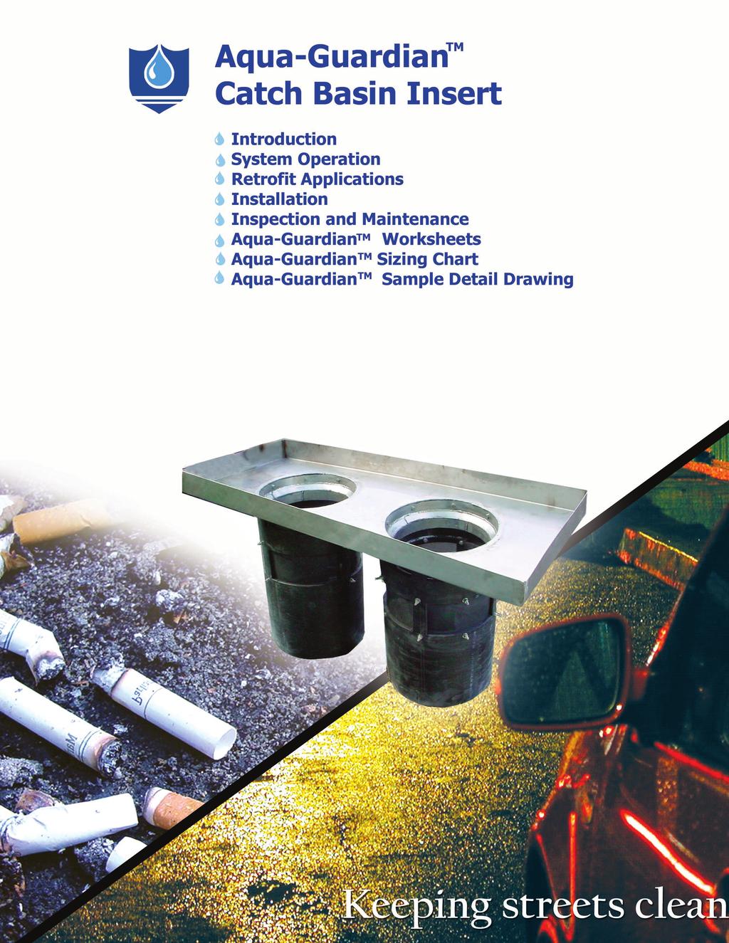
23 Aqua-Guardian Table of Contents AQUA-GUARDIAN...2 Catch Basin Insert...2 System Operation... 2 Retrofit Applications... 3 Installation... 4 Inspection and Maintenance... 4 Aqua-Guardian Worksheet...6 Aqua-Guardian Sizing Chart (English)...10 Aqua-Guardian Sizing Chart (Metric)...11 Aqua-Guardian Sample Detail Drawings Kanasita Drive, Suite B Chattanooga, Tennessee Phone (888) Fax (423)
Table of Contents AQUA-SWIRL 2
 Table of Contents AQUA-SWIRL 2 STORMWATER TREATMENT SOLUTIONS 2 System Operation 2 Custom Applications 4 Retrofit Applications 4 Installation 5 Buoyancy 5 Traffic Loading 6 Inspection and Maintenance 6
Fabrication and Installation Table of Contents
 Fabrication and Installation Table of Contents HDPE AQUASHIELD PRODUCTS 2 Fabrication and Installation 2 System Fabrication 3 Aqua-Swirl Installation 4 Step 1 Excavation and Bedding 4 Step 2 Pipe Connection
Aqua-Swirl Stormwater Treatment System
 Aqua-Swirl Stormwater Treatment System Inspection and Maintenance Manual AquaShield, Inc. 2705 Kanasita Drive, Chattanooga, TN 37343 Phone: (423) 870-8888 Fax: (423) 826-2112 Email: info@aquashieldinc.com
Aqua-Swirl Stormwater Treatment System
 Aqua-Swirl Stormwater Treatment System Inspection and Maintenance Manual AquaShield TM, Inc. 2705 Kanasita Drive Chattanooga, TN 37343 Toll free (888) 344-9044 Phone: (423) 870-8888 Fax: (423) 826-2112
Aqua-Swirl Stormwater Treatment System
 Aqua-Swirl Stormwater Treatment System Inspection and Maintenance Manual AquaShield TM, Inc. 2733 Kanasita Drive Suite 111 Chattanooga, TN 37343 Toll free (888) 344-9044 Phone: (423) 870-8888 Fax: (423)
Bio-Filter TM Stormwater Biofiltration System
 Bio-Filter TM Stormwater Biofiltration System Inspection and Maintenance Manual March 2017 AquaShield, TM Inc. 2733 Kanasita Drive, Suite 111 Chattanooga, TN 37343 Phone: (423) 870-8888 Fax: (423) 826-2112
Table 1: Water Quality Event (WQE) Design Intensities. i 1 (t c 5 min) (in/hr) a b. tc c
 Design Intensities. i 1 (t c 5 min) (in/hr) a b. tc c") Supplemental Technical Specification for Stormwater Manufactured Treatment Devices (MTDs) SCDOT Designation: SC-M-815-13 (8/11) 1.0 Stormwater Manufactured Treatment Devices Stormwater Manufactured Treatment
Supplemental Technical Specification for Stormwater Manufactured Treatment Devices (MTDs) SCDOT Designation: SC-M-815-13 (8/11) 1.0 Stormwater Manufactured Treatment Devices Stormwater Manufactured Treatment
System Maintenance Table of Contents
 Table of Contents AQUASHIELD PRODUCTS 2 System Maintenance 2 Inspection 3 Aqua-Swirl Maintenance 3 Aqua-Swirl Inspection Procedure 3 Aqua-Swirl Cleanout Procedure 4 Aqua-Swirl Inspection Data Sheet 5 Aqua-Swirl
April 19, Mark B. Miller, Research Scientist AquaShield, Inc Kanasita Drive, Suite 111 Chattanooga, Tennessee 37343
 CHRIS CHRISTIE Governor KIM GUADAGNO Lt. Governor DEPARTMENT OF ENVIRONMENTAL PROTECTION Bureau of Nonpoint Pollution Control Division of Water Quality Mail Code 401-02B Post Office Box 420 Trenton, New
Capability of the Aqua-Swirl Concentrator to Remove Trash from Stormwater Runoff
 Capability of the Aqua-Swirl Concentrator to Remove Trash from Stormwater Runoff June 27, 2012 The purpose of this document is to demonstrate the capability of the Aqua-Swirl Concentrator to capture trash
Stormwater Manufactured Treatment Devices (MTDs)
") Supplemental Technical Specification for Stormwater Manufactured Treatment Devices (MTDs) SCDOT Designation: SC-M-815-13 (08/13) 1.0 Stormwater Manufactured Treatment Devices Stormwater Manufactured Treatment
Supplemental Technical Specification for Stormwater Manufactured Treatment Devices (MTDs) SCDOT Designation: SC-M-815-13 (08/13) 1.0 Stormwater Manufactured Treatment Devices Stormwater Manufactured Treatment
Hydrodynamic Separation Product Calculator
 Hydrodynamic Separation Product Calculator Example Project BMP #1 CDS 2015-4 Project Information Project Name Example Project Option # A Country US State Kentucky City Covington Contact Information First
SECTION DOWNSTREAM DEFENDER
 SECTION 02631 DOWNSTREAM DEFENDER PART 1 - GENERAL 1.01 SCOPE A. Work described in this section includes furnishing all labor, equipment, materials, tools and incidentals required for a complete and operable
MATERIALS STORM DRAIN PIPE TABLE OF CONTENTS
 TABLE OF CONTENTS 1. TYPES OF STORM DRAIN PIPE AND JOINTS...2 2. MANHOLES, CATCH BASINS AND INLETS BLOCK AND BRICK...3 3. PRECAST MANHOLES, CATCH BASINS AND INLETS...4 4. STORM DRAIN STUBS...4 5. STORM
Section [ ] Storm Water Treatment Device
![Section [ ] Storm Water Treatment Device](/thumbs/72/67039599.jpg "Section [ ] Storm Water Treatment Device") PART 1 GENERAL Section [ ] Storm Water Treatment Device 01.01.00 Purpose The purpose of this specification is to establish generally acceptable criteria for Storm Water Treatment Devices (SWTD) that treat
PART 1 GENERAL Section [ ] Storm Water Treatment Device 01.01.00 Purpose The purpose of this specification is to establish generally acceptable criteria for Storm Water Treatment Devices (SWTD) that treat
WQ-06 SAND FILTER. 1.0 Sand Filter. Greenville County Technical Specification for: 1.1 Description
 Greenville County Technical Specification for: WQ-06 SAND FILTER 1.0 Sand Filter 1.1 Description Sand Filters remove pollutants through sedimentation and filtration within the sand. The primary components
DRAFT PTP-06. Activity: Water Quality Units
 Shelbyville, Kentucky Stormwater Best Management Practices (BMPs) Stormwater Pollution Treatment Practices (Structural) Activity: Water Quality Units PLANNING CONSIDERATIONS: Design Life: 35 years WQ Acreage
STANDARD SPECIFICATION STORMWATER QUALITY MEMBRANE FILTRATION TREATMENT DEVICE
 STANDARD SPECIFICATION STORMWATER QUALITY MEMBRANE FILTRATION TREATMENT DEVICE PART 1 GENERAL 1.1 WORK INCLUDED Specifies requirements for construction and performance of an underground stormwater quality
BMP 6.4.4: Infiltration Trench
 BMP 6.4.4: Infiltration Trench An Infiltration Trench is a leaky pipe in a stone filled trench with a level bottom. An Infiltration Trench may be used as part of a larger storm sewer system, such as a
Construction Inspection Checklists
 III. Construction Inspection Checklists 33 Bioretention - Construction Inspection Checklist Project: Location: Site Status: Date: Time: Inspector: Construction Sequence Satisfactory / Unsatisfactory Comments
Chapter 12 - Emerging Technologies
 Chapter 12 - Emerging Technologies This Chapter addresses emerging (new) technologies that have not been evaluated in sufficient detail to be acceptable for general usage in new development or redevelopment
SAMPLE SPECIFICATION for HIGH DENSITY POLYETHYLENE PIPING LEACHATE COLLECTION SYSTEMS
 ISCO INDUSTRIES, LLC SAMPLE SPECIFICATION for HIGH DENSITY POLYETHYLENE PIPING LEACHATE COLLECTION SYSTEMS 1. GENERAL This specification shall govern the materials and installation of high density polyethylene
Aqua-Filter Maintenance
 System Maintenance Aqua-Filter Maintenance Proper maintenance of the Aqua-Filter system is needed for the unit to operate efficiently. Typically, inspection of the Aqua-Swirl pretreatment chamber and the
Fiberglass Basin Installation Reference Guide
 Fiberglass Basin Installation Reference Guide PURPOSE The purpose of this is to provide a brief reference to the recommended methods and procedures for installing Topp Industries underground sump and sewage
BAYFILTER SPECIFICATIONS
 PART 1.00 GENERAL 1.1 DESCRIPTION BAYFILTER SPECIFICATIONS A. The BayFilter system s internal components manufacturer selected by the Contractor and approved by the Engineer, shall furnish all labor, materials,
SECTION STORM DRAINAGE
 SECTION 02720 STORM DRAINAGE PART 1 - GENERAL 1.01 WORK INCLUDED A. Trenching and other excavation. B. Ground water control. C. Pipe bedding. D. Installation of storm drains and appurtenances. E. Installation
Inlet Protection. Fe= (Depends on soil type)
") 3.4 DESIGN CRITERIA: KEY CONSIDERATIONS Evaluate drainage patterns to ensure inlet protection will not cause flooding of roadway, property or structures Never block entire inlet opening Size according
3.4 DESIGN CRITERIA: KEY CONSIDERATIONS Evaluate drainage patterns to ensure inlet protection will not cause flooding of roadway, property or structures Never block entire inlet opening Size according
SC-01 Surface Outlet and Baffle Sediment Basin
 Greenville County Technical Specification for: SC-01 Surface Outlet and Baffle Sediment Basin 1.0 Surface Outlet and Baffle Sediment Basin This Specification contains requirements for the design and construction
GWINNETT COUNTY STORM SEWER PIPE STANDARDS
 1.0 Standard Specifications GWINNETT COUNTY STORM SEWER PIPE STANDARDS 1.1 Unless otherwise specifically set forth herein or in the Gwinnett County Standard Drawings, all of the materials, methods of the
Section [ ] Storm Water Treatment Device
![Section [ ] Storm Water Treatment Device](/thumbs/94/121044142.jpg "Section [ ] Storm Water Treatment Device") PART 1 GENERAL Section [ ] Storm Water Treatment Device 01.01.00 Purpose The purpose of this specification is to establish generally acceptable criteria for Storm Water Treatment Devices for treating storm
PART 1 GENERAL Section [ ] Storm Water Treatment Device 01.01.00 Purpose The purpose of this specification is to establish generally acceptable criteria for Storm Water Treatment Devices for treating storm
EFFECTIVE AND EASILY MAINTAINED TREATMENT SOLUTIONS
 EFFECTIVE AND EASILY MAINTAINED TREATMENT SOLUTIONS When it rains, surface runoff carries pollutants, suspended solids and hydrocarbons. Floating debris is swept through collection systems in subsurface
THE ADVANTAGES HDPE MANHOLES
 NIC HDPE manholes are custom fabricated for many varied applications including municipal and industrial manholes, sewer and storm water manholes, leach ate collection, sewer lift stations, siphon structures,
Features: The Most Advanced Name in water management solutions TM
 S4 The Barracuda S4 is a market-changing stormwater quality technology. This high performance vortex hydrodynamic separator is designed to remove total suspended solids in order to protect our precious
Flygt Advanced Low Pressure Sewer System Package
 PURPOSE Xylem The purpose of this document is to provide a brief reference to the recommended methods and procedures for installing Flygt's underground sump and sewage basins to ensure that damage or premature
PERKFILTER. Design Guide
 PERKFILTER Design Guide TABLE OF CONTENTS Description Function Treatment Processes System Hydraulics System Sizing PerkFilter Configurations Inspection and Maintenance Requirements Verification and Approvals
Filterra TM Bioretention System Specification VAULT CONFIGURATION March, 2016
 Filterra TM Bioretention System Specification VAULT CONFIGURATION March, 2016 PART 1 GENERAL 1.1 Description The Contractor shall furnish and install the Filterra TM Bioretention System, complete and operable
Jensen Deflective Separator (JDS) Stormwater Treatment Unit
 Stormwater Treatment Unit") Jensen Deflective Separator (JDS) Stormwater Treatment Unit A Full Capture, Screening, Swirl-Concentrating, Stormwater Treatment Unit The Jensen Deflective Separator (JDS) is a fullcapture, screening,
Jensen Deflective Separator (JDS) Stormwater Treatment Unit A Full Capture, Screening, Swirl-Concentrating, Stormwater Treatment Unit The Jensen Deflective Separator (JDS) is a fullcapture, screening,
SECTION 39 - MANHOLES TABLE OF CONTENTS 39-1 GENERAL PRECAST CONCRETE MANHOLES
 Section SECTION 39 - MANHOLES TABLE OF CONTENTS 39-1 GENERAL... 39-1 39-2 PRECAST CONCRETE MANHOLES... 39-1 39-2.01 Precast Concrete Storm Drain Manholes... 39-1 39-3 SADDLE MANHOLES... 39-2 39-3.01 Saddle
SECTION HIGH DENSITY POLYETHYLENE PIPE AND FITTINGS
 SECTION 02620 PART 1 GENERAL 1.1 SCOPE OF WORK A. Furnish all labor, materials, equipment, and incidentals required to install High Density Polyethylene (HDPE) pressure pipe, fittings, and appurtenances
Chapter 6 Sand Filtration Treatment Facilities
 Sand Filtration Treatment Facilities 6.1 Purpose This chapter presents criteria for the design, construction and maintenance of runoff treatment sand filters. Treatment sand filters are used to collect,
Features: The Most Advanced Name in water management solutions TM
 S4 The Barracuda S4 is a market-changing stormwater quality technology. This high performance vortex hydrodynamic separator is designed to remove total suspended solids in order to protect our precious
STANDARD SPECIFICATION FOR OIL GRIT SEPARATOR (OGS) STORMWATER QUALITY TREAMENT DEVICE
 STORMWATER QUALITY TREAMENT DEVICE") STANDARD SPECIFICATION FOR OIL GRIT SEPARATOR (OGS) STORMWATER QUALITY TREAMENT DEVICE PART 1 GENERAL 1.1 WORK INCLUDED This section specifies requirements for constructing underground stormwater treatment
STANDARD SPECIFICATION FOR OIL GRIT SEPARATOR (OGS) STORMWATER QUALITY TREAMENT DEVICE PART 1 GENERAL 1.1 WORK INCLUDED This section specifies requirements for constructing underground stormwater treatment
INSTALLATION MANUAL. Hydrodynamic Separation. Bio Clean Environmental Services, Inc. 398 Via El Centro Oceanside, CA 92058
 Hydrodynamic Separation INSTALLATION MANUAL Bio Clean Environmental Services, Inc. 398 Via El Centro Oceanside, CA 92058 www.biocleanenvironmental.com p: 760.433.7640 f: 760.433.3176 INSTALLATION PROCEDURES
4.8. Subsurface Infiltration
 4.8. Subsurface Infiltration Subsurface infiltration systems are designed to provide temporary below grade storage infiltration of storm water as it infiltrates into the ground. Dry wells, infiltration
SECTION STORM UTILITY DRAINAGE PIPING PART 1 - GENERAL 1.1 SUMMARY 1.2 SUBMITTALS 1.3 PROJECT CONDITIONS
 SECTION 334100 - STORM UTILITY DRAINAGE PIPING PART 1 - GENERAL 1.1 SUMMARY Section Includes: 1. Pipe and fittings. 2. Drain Basin. 3. De-chlorination tablet feeder. 4. Non-pressure transition couplings.
PASSAIC COUNTY TECHNICAL INSTITUTE CCA 1422 NEW S.T.E.M. BUILDING 2017
 SECTION 02630 - STORM DRAINAGE PART 1 - GENERAL 1.1 RELATED DOCUMENTS A. Drawings and general provisions of the Contract, including General and Supplementary Conditions and Division 01 Specification Sections,
March 15, Mark B. Miller, Research Scientist AquaShield TM, Inc Kanasita Drive, Suite 111 Chattanooga, Tennessee 37343
 KIM GUADAGNO CHRIS CHRISTIE Governor Lt. Governor DEPARTMENT OF ENVIRONMENTAL PROTECTION Bureau of Nonpoint Pollution Control Division of Water Quality 401-02B Post Office Box 420 Trenton, New Jersey 08625-0420
Submittal Requirements. Post Construction Verification Document Plan Requirements
 Submittal Requirements Post Construction Verification Document survey plan in accordance with the items of this Checklist Supporting calculations in accordance with the items of this Checklist A copy of
STANDARD SPECIFICATION FOR OIL GRIT SEPARATOR (OGS) STORMWATER QUALITY TREAMENT DEVICE
 STORMWATER QUALITY TREAMENT DEVICE") STANDARD SPECIFICATION FOR OIL GRIT SEPARATOR (OGS) STORMWATER QUALITY TREAMENT DEVICE PART 1 GENERAL 1.1 WORK INCLUDED This section specifies requirements for constructing underground stormwater treatment
STANDARD SPECIFICATION FOR OIL GRIT SEPARATOR (OGS) STORMWATER QUALITY TREAMENT DEVICE PART 1 GENERAL 1.1 WORK INCLUDED This section specifies requirements for constructing underground stormwater treatment
SPECIAL SPECIFICATION 4425 Thermoplastic Pipe
 2004 Specifications CSJ 0264-07-028 SPECIAL SPECIFICATION 4425 Thermoplastic Pipe 1. Description. Furnish and install thermoplastic pipe for constructing thermoplastic pipe culverts or thermoplastic storm
4.8. Subsurface Infiltration
 4.8. Subsurface Infiltration Subsurface infiltration systems are designed to provide temporary below grade storage infiltration of stormwater as it infiltrates into the ground. Dry wells, infiltration
ITEM 706 PIPE SLOPE DRAIN
 AFTER NOVEMBER 1, 2008 ITEM 706 PIPE SLOPE DRAIN 706.1 Description. This work shall consist of the installation of temporary erosion protection and sediment control pipe slope drains, utilized during construction
STORMFILTER THE MOST PROVEN. stormwater filtration system
 STORMFILTER THE MOST PROVEN stormwater filtration system SOLVES THE MOST STRINGENT PROBLEMATICS in stormwater treatment The evolution and implementation of a more stricter regulatory framework is gradually
SPECIFICATIONS FOR PRECAST MODULAR BLOCK RETAINING WALL SYSTEM (revised 5/8/7)
") Page 1 of 7 STONE STRONG SYSTEMS SPECIFICATIONS FOR PRECAST MODULAR BLOCK RETAINING WALL SYSTEM (revised 5/8/7) PART 1: GENERAL 1.01 Description A. Work includes furnishing and installing precast modular
Page 1 of 7 STONE STRONG SYSTEMS SPECIFICATIONS FOR PRECAST MODULAR BLOCK RETAINING WALL SYSTEM (revised 5/8/7) PART 1: GENERAL 1.01 Description A. Work includes furnishing and installing precast modular
The Most Advanced Name in Water Management Solutions TM. The most cost-effective slotted and trench surface drain systems.
 The Most Advanced Name in Water Management Solutions TM The most cost-effective slotted and trench surface drain systems. A sensible alternative to metal and concrete Since 1987, Duraslot surface drains
STORMWATER MANAGEMENT
 DRAINAGE SOLUTIONS SINCE 1908 STORMWATER MANAGEMENT STORMWATER TREATMENT AND FLOW CONTROL ENVIRONMENTAL PROTECTION EASE OF MAINTENANCE RELIABLE PERFORMANCE ARMTEC.COM STORMWATER TREATMENT Armtec is excited
SPECIFICATION for ISCO HDPE DUAL CONTAINMENT PIPE
 SPECIFICATION for ISCO HDPE DUAL CONTAINMENT PIPE SECTION 15000 MECHANICAL 1. GENERAL 1.1 This specification shall govern the materials and installation of polyethylene dual contained system of pipe, structures
STORMWATER MANAGEMENT
 Distributed by: www.interfaceh2o.com 616-931-5584 STORMWATER MANAGEMENT STORMWATER MANAGEMENT R-Tank stormwater systems provide underground storage of stormwater. After a rain event fills the R-Tank, stormwater
MANHOLES, VAULTS AND CATCH BASINS SECTION A. Section Soil and Aggregate Materials. C. Section Storm Drainage Systems
 SECTION 02607-1 1.0 GENERAL 1.1 SCOPE: A. This section covers the work necessary for the construction of sanitary and storm system manholes, catch basins, and miscellaneous concrete structures complete.
SPECIAL SPECIFICATION 4653 Polypropylene Pipe
 2004 Specifications CSJ 2158-01-013, Etc. SPECIAL SPECIFICATION 4653 Polypropylene Pipe 1. Description. Furnish and install polypropylene pipe for constructing polypropylene pipe culverts or polypropylene
EROSION AND SEDIMENTATION CONTROL SECTION 1 - GENERAL 1.1 SUMMARY
 31 25 00 EROSION AND SEDIMENTATION CONTROL SECTION 1 - GENERAL 1.1 SUMMARY A. Erosion and sedimentation control shall be provided by the Contractor for all areas of the site denuded or otherwise disturbed
PERMANENT PAVEMENT REPAIR NO SCALE
 SAWCUT EXISTING PAVEMENT 2" BITUMINOUS CONCRETE SURFACE COURSE, CLASS 2 (MIN) CLEAN EDGE PRIOR TO PAVING AND PAINT WITH LIQUID BITUMEN. INSTALL SEALANT OVER JOINT UPON COMPLETION 2" BITUMINOUS CONCRETE
4.28 Underground Detention
 4.28 Underground Detention Detention Structural Stormwater Control Description: Detention storage located in underground tanks or vaults designed to provide water quantity control through detention and/or
STORMWATER TREATMENT FIELD DEMONSTRATION AND EVALUATION
 STORMWATER TREATMENT FIELD DEMONSTRATION AND EVALUATION Frank Sagona 1, Doyle Dobson 2, Mark Miller 3 AUTHORS: 1 Watershed Director, Conasauga River Alliance, 125 Redbud Road NE Suite 7, 2 Doyle Dobson,
4.4.6 Underground Detention
 4.4.6 Underground Detention Limited Application Water Quality BMP Description: Detention storage located in underground pipe systems or vaults designed to provide water quantity control through detention
Technical Data Sheet NEC/GRAN/95:01
 Technical Data Sheet NEC/GRAN/95:01 Installation Guidance Notes Granular Surround Note : These guidance notes refer only to the installation of Granular surround underground tanks. These guidance notes
SECTION STORM DRAINAGE UTILITIES. B. Section : Site Restoration and Rehabilitation
 SECTION 33 40 00 STORM DRAINAGE UTILITIES 1. PART 1 GENERAL 1.1 RELATED WORK A. Section 31 23 00: Excavation and Fill B. Section 32 00 01: Site Restoration and Rehabilitation C. Special Conditions for
SECTION FACILITY SANITARY SEWERS
 SECTION 22 13 13 FACILITY SANITARY SEWERS PART 1 - GENERAL 1.1 RELATED DOCUMENTS A. Drawings and general provisions of the Contract, including General and Supplementary Conditions and Division 01 Specification
SECTION UTILITY POLYETHYLENE CONTAINMENT PIPE SYSTEMS
 SECTION 02670 UTILITY POLYETHYLENE CONTAINMENT PIPE SYSTEMS PART 1 - GENERAL 1.01 WORK INCLUDED A. Trenching and other excavation. B. Ground water control. C. Pipe bedding. D. Installation of containment
TYPE "A" CATCH BASIN
 27" 1.67' TO BACK OF CURB LINE TOP OF GRATE ELEV. - SEE PLAN NEENAH CASTING R-3250-BV OR APPROVED EQUAL. "INFI SHIELD" SEAL OR APPROVED EQUAL RINGS (2 MIN., 1' MAX. OF RINGS AND MORTAR). PLASTER OUTSIDE,
Figure Inlet protection (Source: Minnesota DOT)
") 3.9 INLET PROTECTION Figure 3.14. Inlet protection (Source: Minnesota DOT) Overview Description: A manufactured protective device or barrier used to trap sediment at a storm drain surface or curb inlet.
3.9 INLET PROTECTION Figure 3.14. Inlet protection (Source: Minnesota DOT) Overview Description: A manufactured protective device or barrier used to trap sediment at a storm drain surface or curb inlet.
1. Division 01 Section General Requirements - Temporary Facilities and Controls. 2. Division 31 Section Earthwork.
 PAGE 334000-1 SECTION 334000 PART 1 - GENERAL 1.1 RELATED DOCUMENTS A. Drawings and general provisions of the Contract, including General and Supplementary Conditions and Division 01 Specification sections,
TYPICAL INSTALLATION INSTRUCTIONS
 TYPICAL INSTALLATION INSTRUCTIONS Environment One Grinder Pump Feature Identification 1. Grinder Pump Basin High density polyethylene (HDPE) 2. Accessway Cover Painted Steel 3. Electrical Quick Disconnect
SV24. Submittal Special Precautions Specifications Installation. 12½" (31.8 cm) 12½" (31.8 cm) 12" (30.5 cm) 12" (30.5 cm) 12" (30.
 12½ (31.8 cm) 12 (30.5 cm) 12 (30.5 cm) 12 (30.") Wastewater Sampling Port Technical Data Submittal Special Precautions Specifications Installation 16½" (31.8 (41.9 cm) 8" (20.3 cm) -L -O SUBMITTAL STANDARD: 4" plain end inlet/outlet Highway traffic load
Wastewater Sampling Port Technical Data Submittal Special Precautions Specifications Installation 16½" (31.8 (41.9 cm) 8" (20.3 cm) -L -O SUBMITTAL STANDARD: 4" plain end inlet/outlet Highway traffic load
Chapter 5 Hydraulic Structures
 Chapter 5 Hydraulic Structures 5.1 Flow Splitter Designs 5.1.1 General Design Criteria A flow splitter must be designed to deliver the WQ design flow rate specified in this volume to the WQ treatment facility.
ITEM D-701 PIPE FOR STORM DRAINS AND CULVERTS
 ITEM D-701 PIPE FOR STORM DRAINS AND CULVERTS 701-1 DESCRIPTION 701-1.1 This item shall consist of the construction of pipe culverts, and storm drains, removal of existing storm pipes, connections to existing
This type of masonry shall consist of brick laid in full beds of cement mortar.
 SECTION 11.0 DRAINAGE STRUCTURES 11.01 Scope of Work This item shall consist of installation and construction of storm drainage pipes, culverts, basins, headwalls, manholes, junction boxes, head ditches,
Innovation In Stormwater Management
 Innovation In Stormwater Management DETENTION/RETENTION PERMEABLE SOLUTIONS HARVESTING/REUSE BIORETENTION/BIOFILTRATION MEDIA FILTRATION HYDRODYNAMIC SEPARATION INLET FILTRATION TRASH CAPTURE Oldcastle
SECTION STORM SEWER PIPE
 SECTION 4200 - STORM SEWER PIPE 4200.1 SCOPE: This section covers the requirements for all labor, equipment and materials for the installation of storm sewers pipes. Trenching guidelines are provided in
ENGINEERING CHECKLIST SEDIMENT & STORMWATER MANAGEMENT BASIN CONSTRUCTION
 NEW CASTLE COUNTY DEPARTMENT OF LAND USE ENGINEERING CHECKLIST SEDIMENT & STORMWATER MANAGEMENT BASIN CONSTRUCTION For Permanent Structures, pursuant to Delaware Pond Code 378 and Delaware Sediment and
ACTIVITY: Dewatering Operations AM 12
 Targeted Constituents Significant Benefit Partial Benefit Low or Unknown Benefit Sediment Heavy Metals Floatable Materials Oxygen Demanding Substances Nutrients Toxic Materials Oil & Grease Bacteria &
WehoManholes. WehoManhole Ordering Guide. WehoManhole Ordering Guide
 WehoManholes WehoManhole Ordering Guide WehoManhole Ordering Guide WehoManhole Ordering Guide Weholite Pipe s smooth inner and outer wall make economical fabrication of polyethylene manholes and other
Klickitat County. On-Site Sewage System. Construction Manual
 Homeowner OSS Design and Construction Guide Klickitat County On-Site Sewage System Construction Manual Minimum standards and recommendations expected for the construction of on-site wastewater treatment
SECTION 39 - MANHOLES TABLE OF CONTENTS
 Section SECTION 39 - MANHOLES TABLE OF CONTENTS Page 39-1 GENERAL... 39.1 39-2 CONCRETE MANHOLES... 39.1 39-2.01 NOT USED... 39.1 39-2.02 Concrete Storm Drain Manholes... 39.1 39-3 SADDLE SEWER MANHOLES...
FS-DUO. Wastewater Flow Distributor Technical Data. Submittal Special Precautions Specifications Installation. (62.2 cm) (62.2 cm)
 (62.2 cm)") Wastewater Flow Distributor Technical Data Submittal Special Precautions Specifications Installation 24½" (62.2 cm) 12½" (31.8 cm) 24½" (62.2 cm) (30.5 cm) SUBMITTAL STANDARD: 4" plain end inlet/outlet
Wastewater Flow Distributor Technical Data Submittal Special Precautions Specifications Installation 24½" (62.2 cm) 12½" (31.8 cm) 24½" (62.2 cm) (30.5 cm) SUBMITTAL STANDARD: 4" plain end inlet/outlet
GB-20. Submittal Specifications Installation Application Specific Details
 GREASE INTERCEPTOR TECHNICAL DATA Submittal Specifications Installation Application Specific Details 27" (68.6 cm) 4¼" (10.8 cm) 15" (38.1 cm) 10¾" (27.3 cm) SUBMITTAL (53.3 cm) STANDARD: 2" plain end
Weholite LIGHTWEIGHT PIPE SYSTEM
 Weholite LIGHTWEIGHT PIPE SYSTEM The lightweight pipe that takes a heavier load Weholite pipe is large diameter, profile wall pipe made from highdensity polyethylene (HDPE) resin, which is manufactured
SECTION UTILITY MANHOLES AND STRUCTURES
 SECTION 33 05 14 UTILITY MANHOLES AND STRUCTURES PART 1 GENERAL 1.1 SUMMARY A. Section Includes: 1. Precast reinforced concrete manholes and structures with tongue-and-groove joints with masonry transition
TABLE OF CONTENTS
 DIVISION 33: SEWER AND SEPTIC SYSTEMS 33 3633 UTILITY SEPTIC TANK DRAINAGE FIELD TABLE OF CONTENTS 33 0000-1 SECTION 33 3633-- UTILITY SEPTIC TANK DRAINAGE FIELD PART 1 - GENERAL 1.1 SUMMARY A. Includes
Sorbtive Vault Operations & Maintenance Manual
 Media Sorbtive Vault Operations & Maintenance Manual Overview These instructions provide a description of the operation, inspection and maintenance aspects of Sorbtive Vault. Safety Notice Jobsite safety
PVC. System Specifications TABLE 1 TABLE 2
 TRICON PVC TABLE 1 Pipe Size Minimum Insulation Thickness PVC Jacket O.D. PVC Jacket Wall 2 1.81 6.14.070 3 1.25 6.14.070 4 1.75 8.16.080 6 1.69 10.20.100 8 1.69 12.24.120 10 1.65 14.32.140 12 1.47 16.00.160
B. Install storm drain inlet protection to prevent clogging of the stormsewer and sediment loads to downstream stormwater facilities or waterbodies.
 The language provided in these specifications is meant to serve as a reminder and provide a generic example of the type of language that should be provided in final construction documents. This language
DETENTION, RETENTION AND RECHARGE STRUCTURES
 DETENTION, RETENTION AND RECHARGE STRUCTURES Introduction Foundation, trenchwall, bedding and backfill considerations for multiple barrel detention systems are not unlike those for conventional CSP installations.
Contactor & Recharger Stormwater Chambers
 CULTEC Stormwater Chambers Contactor & Recharger Stormwater Chambers Operation and Maintenance Guidelines for CULTEC Stormwater Management Systems The Founder of Plastic Chamber Technology www.cultec.com
ACTIVITY: Water Quality Inlets and Media Filtration Inlets ST 06
 Flow Sedimentation basin Sand filter Filtered runoff Targeted Constituents Significant Benefit Partial Benefit Low or Unknown Benefit Sediment Heavy Metals Floatable Materials Oxygen Demanding Substances
BIG 'O' HDPE Tubing CORRUGATED TUBING FOR AGRICULTURAL, RESIDENTIAL AND HIGHWAY DRAINAGE. Proudly owned and operated in Canada. aquaq.
 BIG 'O' HDPE Tubing CORRUGATED TUBING FOR AGRICULTURAL, RESIDENTIAL AND HIGHWAY DRAINAGE aquaq.ca Proudly owned and operated in Canada. BIG 'O' HDPE TUBING The most recognized brand name for HDPE TUBING
Section [ ] Stormwater Catch Basin Filtration Device
![Section [ ] Stormwater Catch Basin Filtration Device](/thumbs/75/71497296.jpg "Section [ ] Stormwater Catch Basin Filtration Device") PART 1 GENERAL Section [ ] Stormwater Catch Basin Filtration Device 01.01.00 Purpose The purpose of this specification is to establish generally acceptable criteria for devices used for filtration of stormwater
PART 1 GENERAL Section [ ] Stormwater Catch Basin Filtration Device 01.01.00 Purpose The purpose of this specification is to establish generally acceptable criteria for devices used for filtration of stormwater
Section [ ] Stormwater Catch Basin Filtration Device
![Section [ ] Stormwater Catch Basin Filtration Device](/thumbs/88/117533878.jpg "Section [ ] Stormwater Catch Basin Filtration Device") PART 1 GENERAL Section [ ] Stormwater Catch Basin Filtration Device 01.01.00 Purpose The purpose of this specification is to establish generally acceptable criteria for devices used for filtration of stormwater
PART 1 GENERAL Section [ ] Stormwater Catch Basin Filtration Device 01.01.00 Purpose The purpose of this specification is to establish generally acceptable criteria for devices used for filtration of stormwater
SPECIFICATIONS FOR PRECAST MODULAR BLOCK RETAINING WALL SYSTEM (revised 9/17/18)
") Page 1 of 8 STONE STRONG SYSTEMS SPECIFICATIONS FOR PRECAST MODULAR BLOCK RETAINING WALL SYSTEM (revised ) PART 1: GENERAL 1.01 Description A. Work includes furnishing and installing precast modular blocks
Page 1 of 8 STONE STRONG SYSTEMS SPECIFICATIONS FOR PRECAST MODULAR BLOCK RETAINING WALL SYSTEM (revised ) PART 1: GENERAL 1.01 Description A. Work includes furnishing and installing precast modular blocks