Application for Temporary Air Permit University of New Hampshire Turnkey Landfill Gas to Energy Project
|
|
|
- Bryan Green
- 6 years ago
- Views:
Transcription
1 Application for Temporary Air Permit University of New Hampshire Turnkey Landfill Gas to Energy Project Prepared for: University of New Hampshire 22 Colovos Road Durham, NH March 23, 2007
2 March 23, 2007 Mr. Gary Milbury New Hampshire Department of Environmental Services Air Resources Division 29 Hazen Drive P.O. Box 95 Concord, NH Revised Application for Temporary Air Permit: University of New Hampshire Landfill Gas to Energy Project Dear Gary: On behalf of the University of New Hampshire, MacMillan & Donnelly is submitting the enclosed revised temporary air permit application for UNH s proposed landfill gas to energy (LFGTE) project at the Waste Management Turnkey Landfill site. Due to project design modifications, two stationary internal combustion engines will replace the proposed Centaur turbine at the Rochester site. UNH s permit application, including control technology analyses and modeling analyses, has been updated to reflect this design change. All sources owned and operated by the University of New Hampshire are in compliance with all applicable emission limitations and standards under the Clean Air Act. Included with this application packet is a CD containing the necessary modeling files and a certification of accuracy statement signed by a UNH responsible official. Please call me if you have any questions or require additional information. Sincerely, Tim Donnelly cc: Allan Braun, Braun Consulting Paul Chamberlin, University of New Hampshire Jim Dombrosk, University of New Hampshire Jeff Pierce, SCS Energy
3 New Hampshire Department of Environmental Services Air Resources Division University of New Hampshire 22 Colovos Road Durham, NH Certification of Accuracy Statement for UNH Landfill Gas to Energy Project Temporary Air Permit Application I am authorized to make this submission on behalf of the facility for which the submission is made. Based on information and belief formed after reasonable inquiry, the statements and information in this submittal are true, accurate and complete. The University of New Hampshire will use the NOx emission reduction credits (ERCs) for offsetting purposes in a non-attainment area and the ERCs will not be used in a manner prohibited under New Hampshire DES regulation. This permit application includes an air impact analysis demonstrating compliance with the NAAQS, except for ground level ozone, for criteria pollutants and compliance with Env-A1400 for toxic air pollutants. Based the results of the modeling analysis, the University of New Hampshire is in compliance with all NAAQS, except for ground level ozone, and all AALs for toxics. I am aware that there are significant penalties for submitting false statements and information or omitting required statements and information, including the possibility of fine or imprisonment. Signed: Title: Date:
4 Table of Contents Section 1: Section 2: Section 3: ARD-1 and ARD-2 Forms Control Technology Analyses Air Dispersion Modeling Summary Attachments A: Facility Site Plan and Location of Facility on a USGS Topographical Map B: Emission Calculations C: BPIP-Prime Inputs D: Maximum Impact Summary and RTAP Summary
5
6 STATE OF NEW HAMPSHIRE Department of Environmental Services Air Resources Division P.O. Box 95 Concord, NH Telephone: Form ARD-1 General Information for All Permit Applications I. FACILITY INFORMATION - Complete the following: A. Type of Application: New Renewal Modification B. Physical Location: C. Mailing Address: UNH Gas Processing Facility Facility Name Rochester Neck Road Street/P.O. Box Rochester Neck Road Rochester NH Street Town/City State Zip Code Rochester NH N/A Town/City State Zip Code Telephone Number D. USGS or Latitude/Longitude UTM Coordinates: Easting: N Latitude: Deg Min Sec Northing: W Longitude: Deg Min Sec E. Owner: F. Parent Corporation: The University of New Hampshire, c/o UNH Facilities Design & Construct. University System of New Hampshire Company Company 22 Colovos Road Edward MacKay, Vice Chancellor & Street/P.O. Box Treasure Contact Person/Title Durham NH Concord Road Town/City: State Zip Code Street/P.O. Box Durham NH Telephone Number Town/City: State Zip Code G. Contact Information Telephone Number 1. General/Technical Contact: 2. Application Preparation: Jim Dombrosk MacMillan and Donnelly, Inc. Contact Person Company Director of Energy & Utilities Tim Donnelly Title Contact Person 17 Leavitt Lane 361 U.S. Route One Address Address Durham NH Falmouth ME Town/City State Zip Code Town/City State Zip Code Telephone Number Telephone Number jim.dombrosk@unh.edu tdonnelly@mdeec.com Address Address
7 Page 2 of 3 Form ARD-1 3. Legal Contact: 4. Invoicing Contact: Ronald F. Rogers Contact Person General Counsel and Secretary, USNH Title Meyers Center, 27 Concord Road Address Irving Canner Contact Person Exec. Director Facilities Management Title 6 Leavitt Lane Address Durham NH Durham NH Town/City State Zip Code Town/City State Zip Code Telephone Number Telephone Number Ron.Rodgers@unh.edu Address irving.canner@unh.edu Address H. Major Activity or Product Descriptions - List all activities performed at this facility and provide SIC code(s): Description of Activity or Product SIC Code landfill gas processing 4939 electricity generation 4911 I. Other Sources or Devices - List sources or devices at the facility (other than those that are the subject of this application) that are permitted pursuant to Env-A 600: Source or Device Permit # Expiration Date EU1 -EU13 TV-OP-010 6/30/04 Combustion Turbine, Duct burner, and BSEG FP-T /31/06 II. Total Facility Emissions Data: Pollutant CAS # Actual (lb/hr) Potential (lb/hr) Actual (ton/yr) Potential (ton/yr) NOx SO CO VOC PM Note: For Regulated Toxic Air Pollutants list name and Chemical Abstract Service Number (CAS #) use additional sheets if necessary.
8 Page 3 of 3 Form ARD-1 III. IV. Support Data The following data must be submitted with this application: A copy of all calculations used in determining emissions; A copy of a USGS map section with the site location clearly indicated; and A to-scale site plan of the facility showing: 1. the locations of all emission points; 2. the dimensions of all buildings, including roof heights; and 3. the facility s property boundary. Certification (To be completed by a responsible official only): I am authorized to make this submission on behalf of the affected source or affected units for which this submission is made. I certify under penalty of law that I have personally examined, and am familiar with, the information submitted in this document and all of its attachments. Based on my inquiry of those individuals with primary responsibility for obtaining the information, I certify that the statements and information are to the best of my knowledge and belief true, accurate, and complete. I am aware that there are significant penalties for submitting false statements and information or omitting required statements and information, including the possibility of fine or imprisonment. Print/Type Name: Paul D. Chamberlin Signed: Title: Interim Assistant V.P.-Facilities Date:
9 STATE OF NEW HAMPSHIRE Department of Environmental Services Air Resources Division Form ARD-2 Information Required for Permits for Fuel Burning Devices I. EQUIPMENT INFORMATION Complete a separate form for each device. Device Description: Reciprocating Engine #1 Date Construction Commenced: Expected Spring 2007 Device Start-Up Date: Early 2008 Expected A. Boiler Not Applicable Boiler Manufacturer Boiler Model Number Boiler Serial Number Gross Heat Input Nameplate Rating (MMBtu/hr) Burner Manufacturer Burner Model Number gal/hr mmcf/hr ton/hr Burner Serial Number Potential Fuel Flow Rate 1. Type of Burner: a. Solid Fuel: b. Liquid Fuel: c. Gaseous Fuel: Cyclone Pressure Gun Natural Gas Pulverized ( wet dry) Rotary Cup Propane Spreader Stoker Steam Atomization Other (specify): Underfeed Stoker Overfeed Stoker Hand-Fired Fly Ash Re-injection Other (specify): 2. Combustion Type: Air Atomization Other (specify): Tangential Firing Opposite End Firing Limited Excess Firing Flue Gas Recirculation Staged Combustion Biased Firing One End Only Firing Other (specify): B. Internal Combustion Engines/Combustion Turbines Not Applicable Caterpillar Manufacturer TBD Serial Number 1600 Engine Output Rating hp G3520C Model Number 14.3 MMBtu/hr Fuel Flow Rate kw Power Generation Reason for Engine Use gal/hr mmcf/hr Revision Date: October 30, 2003
10 Device: Reciprocating Engine #1 Page 2 of 4 C. Stack Information Is unit equipped with multiple stacks? Yes No (if yes, provide data for each stack) Identify other devices on this stack: Is Section 123 of the Clean Air Act applicable? Yes No Is stack monitoring used? Yes No If yes, Describe: Is stack capped or otherwise restricted? Yes No If yes, Describe: Stack exit orientation: Vertical Horizontal Downward Form ARD Stack Inside Diameter (ft) Exit Area (ft 2 ) Discharge height above ground level (ft) 11, Exhaust Flow (acfm) Exhaust Velocity (ft/sec) 896 Exhaust Temperature ( F) II. OPERATIONAL INFORMATION A. Fuel Usage Information 1. Fuel Supplier: 2. Fuel Additives: N/A Supplier s Name N/A Manufacturer s Name Street Street Town/City State Zip Code Town/City State Zip Code Telephone Number Telephone Number Identification of Additive 3. Fuel Information (List each fuel utilized by this device): Type % Sulfur % Ash % Moisture (solid fuels only) Consumption Rate (gallons per 1000 gallons of fuel) Heat Rating (specify units) Potential Heat Input (MMBtu/hr) Actual Annual Usage (specify units) LFG 40 ppm N/A N/A 500Btu/cf 14.3 N/A B. Hours of Operation Hours per day: 24 Days per year: 365 Note: Emission calculations are based on 97% uptime. Revision Date: October 30, 2003
11 Device: Reciprocating Engine #1 Page 3 of 4 III. POLLUTION CONTROL EQUIPMENT Not Applicable A. Type of Equipment Note: if process utilizes more than one control device, provide data for each device baffled settling chamber long cone cyclone wide bodied cyclone irrigated long cone cyclone multiple cyclone ( inch diameter) carbon absorption electrostatic precipitator spray tower venturi scrubber afterburners (incineration) selective catalytic reduction reburn other (specify): B. Pollutant Input Information irrigated electrostatic precipitator absorption tower baghouse packed tower/column selective non-catalytic reduction Form ARD-2 Pollutant Temperature ( F) Actual (lb/hr) Potential (lb/hr) Actual (ton/yr) Potential (ton/yr) Method used to determine entering emissions: other (specify): stack test vendor data emission factor material balance C. Operating Data 1. Capture Efficiency: % Verified by: test calculations 2. Control Efficiency: % Verified by: test calculations 3. Normal Operating Conditions (supply the following data as applicable) Total gas volume through unit (acfm) Temperature ( F) Percent Carbon Dioxide (CO 2 ) Voltage Spark Rate Milliamps Pressure Drop (inches of water) Liquid Recycle Rate (gallons per minute) Revision Date: October 30, 2003
12 Device: Reciprocating Engine #1 Page 4 of 4 Form ARD-2 IV. DEVICE EMISSIONS DATA: Temperature Actual Potential Actual Potential Pollutant ( F) (lb/hr) (lb/hr) (ton/yr) (ton/yr) NOx 896 N/A 2.5 N/A CO 896 N/A 13.5 N/A VOC 896 N/A 3.4 N/A PM N/A 0.5 N/A 2.09 SOx 896 N/A 0.2 N/A 0.97 Method used to determine exiting emissions: stack test vendor data emission factor material balance other (specify): Revision Date: October 30, 2003
13 STATE OF NEW HAMPSHIRE Department of Environmental Services Air Resources Division Form ARD-2 Information Required for Permits for Fuel Burning Devices I. EQUIPMENT INFORMATION Complete a separate form for each device. Device Description: Reciprocating Engine #2 Date Construction Commenced: Expected Spring 2007 Device Start-Up Date: Expected Fall 2007 A. Boiler Not Applicable Boiler Manufacturer Boiler Model Number Boiler Serial Number Gross Heat Input Nameplate Rating (MMBtu/hr) Burner Manufacturer Burner Model Number gal/hr mmcf/hr ton/hr Burner Serial Number Potential Fuel Flow Rate 1. Type of Burner: a. Solid Fuel: b. Liquid Fuel: c. Gaseous Fuel: Cyclone Pressure Gun Natural Gas Pulverized ( wet dry) Rotary Cup Propane Spreader Stoker Steam Atomization Other (specify): Underfeed Stoker Overfeed Stoker Hand-Fired Fly Ash Re-injection Other (specify): 2. Combustion Type: Air Atomization Other (specify): Tangential Firing Opposite End Firing Limited Excess Firing Flue Gas Recirculation Staged Combustion Biased Firing One End Only Firing Other (specify): B. Internal Combustion Engines/Combustion Turbines Not Applicable Caterpillar Manufacturer TBD Serial Number 1600 Engine Output Rating hp G3520C Model Number 14.3 MMBtu/hr Fuel Flow Rate kw Power Generation Reason for Engine Use gal/hr mmcf/hr Revision Date: October 30, 2003
14 Device: Reciprocating Engine #2 Page 2 of 4 C. Stack Information Is unit equipped with multiple stacks? Yes No (if yes, provide data for each stack) Identify other devices on this stack: Is Section 123 of the Clean Air Act applicable? Yes No Is stack monitoring used? Yes No If yes, Describe: Is stack capped or otherwise restricted? Yes No If yes, Describe: Stack exit orientation: Vertical Horizontal Downward Form ARD Stack Inside Diameter (ft) Exit Area (ft 2 ) Discharge height above ground level (ft) 11, Exhaust Flow (acfm) Exhaust Velocity (ft/sec) 896 Exhaust Temperature ( F) II. OPERATIONAL INFORMATION A. Fuel Usage Information 1. Fuel Supplier: 2. Fuel Additives: N/A Supplier s Name N/A Manufacturer s Name Street Street Town/City State Zip Code Town/City State Zip Code Telephone Number Telephone Number Identification of Additive 3. Fuel Information (List each fuel utilized by this device): Type % Sulfur % Ash % Moisture (solid fuels only) Consumption Rate (gallons per 1000 gallons of fuel) Heat Rating (specify units) Potential Heat Input (MMBtu/hr) Actual Annual Usage (specify units) LFG 40 ppm N/A N/A 500Btu/cf 14.3 N/A B. Hours of Operation Hours per day: 24 Days per year: 365 Note: Emission calculations are based on 97% uptime. Revision Date: October 30, 2003
15 Device: Reciprocating Engine #2 Page 3 of 4 III. POLLUTION CONTROL EQUIPMENT Not Applicable A. Type of Equipment Note: if process utilizes more than one control device, provide data for each device baffled settling chamber long cone cyclone wide bodied cyclone irrigated long cone cyclone multiple cyclone ( inch diameter) carbon absorption electrostatic precipitator spray tower venturi scrubber afterburners (incineration) selective catalytic reduction reburn other (specify): B. Pollutant Input Information irrigated electrostatic precipitator absorption tower baghouse packed tower/column selective non-catalytic reduction Form ARD-2 Pollutant Temperature ( F) Actual (lb/hr) Potential (lb/hr) Actual (ton/yr) Potential (ton/yr) Method used to determine entering emissions: other (specify): stack test vendor data emission factor material balance C. Operating Data 1. Capture Efficiency: % Verified by: test calculations 2. Control Efficiency: % Verified by: test calculations 3. Normal Operating Conditions (supply the following data as applicable) Total gas volume through unit (acfm) Temperature ( F) Percent Carbon Dioxide (CO 2 ) Voltage Spark Rate Milliamps Pressure Drop (inches of water) Liquid Recycle Rate (gallons per minute) Revision Date: October 30, 2003
16 Device: Reciprocating Engine #2 Page 4 of 4 Form ARD-2 IV. DEVICE EMISSIONS DATA: Temperature Actual Potential Actual Potential Pollutant ( F) (lb/hr) (lb/hr) (ton/yr) (ton/yr) NOx 896 N/A 2.5 N/A CO 896 N/A 13.5 N/A VOC 896 N/A 3.4 N/A PM N/A 0.5 N/A 2.09 SOx 896 N/A 0.2 N/A 0.97 Method used to determine exiting emissions: stack test vendor data emission factor material balance other (specify): Revision Date: October 30, 2003
17 STATE OF NEW HAMPSHIRE Department of Environmental Services Air Resources Division Form ARD-2 Information Required for Permits for Fuel Burning Devices I. EQUIPMENT INFORMATION Complete a separate form for each device. Device Description: 43.6 MMBtu/hr Recuperative Turbine Date Construction Commenced: Expected Spring 2008 Device Start-Up Date: Early 2009 Expected A. Boiler Not Applicable Boiler Manufacturer Boiler Model Number Boiler Serial Number Gross Heat Input Nameplate Rating (MMBtu/hr) Burner Manufacturer Burner Model Number gal/hr mmcf/hr ton/hr Burner Serial Number Potential Fuel Flow Rate 1. Type of Burner: a. Solid Fuel: b. Liquid Fuel: c. Gaseous Fuel: Cyclone Pressure Gun Natural Gas Pulverized ( wet dry) Rotary Cup Propane Spreader Stoker Steam Atomization Other (specify): Underfeed Stoker Overfeed Stoker Hand-Fired Fly Ash Re-injection Other (specify): 2. Combustion Type: Air Atomization Other (specify): Tangential Firing Opposite End Firing Limited Excess Firing Flue Gas Recirculation Staged Combustion Biased Firing One End Only Firing Other (specify): B. Internal Combustion Engines/Combustion Turbines Not Applicable Solar Turbines Mercury R Manufacturer Model Number TBD Serial Number 4,500 Engine Output Rating hp Fuel Flow Rate kw Electrical Generation Reason for Engine Use gal/hr mmcf/hr Revision Date: October 30, 2003
18 Device: Recuperative Turbine Page 2 of 4 C. Stack Information Is unit equipped with multiple stacks? Yes No (if yes, provide data for each stack) Identify other devices on this stack: Is Section 123 of the Clean Air Act applicable? Yes No Is stack monitoring used? Yes No If yes, Describe: Is stack capped or otherwise restricted? Yes No If yes, Describe: Stack exit orientation: Vertical Horizontal Downward Form ARD to be determined Stack Inside Diameter (ft) Exit Area (ft 2 ) Discharge height above ground level (ft) 69, Exhaust Flow (acfm) Exhaust Velocity (ft/sec) Exhaust Temperature ( F) II. OPERATIONAL INFORMATION A. Fuel Usage Information 1. Fuel Supplier: 2. Fuel Additives: N/A Supplier s Name N/A Manufacturer s Name Street Street Town/City State Zip Code Town/City State Zip Code Telephone Number Telephone Number Identification of Additive 3. Fuel Information (List each fuel utilized by this device): Type % Sulfur % Ash % Moisture (solid fuels only) Consumption Rate (gallons per 1000 gallons of fuel) Heat Rating (specify units) Potential Heat Input (MMBtu/hr) Actual Annual Usage (specify units) LFG 4 ppm N/A N/A 752Btu/scf 43.6 N/A B. Hours of Operation Hours per day: 24 Days per year: 365 Note: Emission calculations are based on 97% uptime. Revision Date: October 30, 2003
19 Device: Recuperative Turbine Page 3 of 4 III. POLLUTION CONTROL EQUIPMENT Not Applicable A. Type of Equipment Note: if process utilizes more than one control device, provide data for each device baffled settling chamber long cone cyclone wide bodied cyclone irrigated long cone cyclone multiple cyclone ( inch diameter) carbon absorption electrostatic precipitator spray tower venturi scrubber afterburners (incineration) selective catalytic reduction reburn other (specify): B. Pollutant Input Information irrigated electrostatic precipitator absorption tower baghouse packed tower/column selective non-catalytic reduction Form ARD-2 Pollutant Temperature ( F) Actual (lb/hr) Potential (lb/hr) Actual (ton/yr) Potential (ton/yr) Method used to determine entering emissions: other (specify): stack test vendor data emission factor material balance C. Operating Data 1. Capture Efficiency: % Verified by: test calculations 2. Control Efficiency: % Verified by: test calculations 3. Normal Operating Conditions (supply the following data as applicable) Total gas volume through unit (acfm) Temperature ( F) Percent Carbon Dioxide (CO 2 ) Voltage Spark Rate Milliamps Pressure Drop (inches of water) Liquid Recycle Rate (gallons per minute) Revision Date: October 30, 2003
20 Device: Recuperative Turbine Page 4 of 4 Form ARD-2 IV. DEVICE EMISSIONS DATA: Temperature Actual Potential Actual Potential Pollutant ( F) (lb/hr) (lb/hr) (ton/yr) (ton/yr) NOx 731 N/A 0.8 N/A 3.17 CO 731 N/A 1.0 N/A 3.80 VOC 731 N/A 0.6 N/A 2.24 PM N/A 1.8 N/A 7.25 SOx 731 N/A 0.1 N/A 0.26 Method used to determine exiting emissions: stack test vendor data emission factor material balance other (specify): Revision Date: October 30, 2003
21 STATE OF NEW HAMPSHIRE Department of Environmental Services Air Resources Division Form ARD-2 Information Required for Permits for Fuel Burning Devices I. EQUIPMENT INFORMATION Complete a separate form for each device. Device Description: MMBtu/hr Supplemental Flare Date Construction Commenced: Spring 2007 Expected Device Start-Up Date: Early 2008 Expected A. Boiler Not Applicable Boiler Manufacturer Boiler Model Number Boiler Serial Number Gross Heat Input Nameplate Rating (MMBtu/hr) Burner Manufacturer Burner Serial Number 1. Type of Burner: Burner Model Number Potential Fuel Flow Rate a. Solid Fuel: b. Liquid Fuel: c. Gaseous Fuel: Cyclone Pressure Gun Natural Gas Pulverized ( wet dry) Rotary Cup Propane Spreader Stoker Steam Atomization Other (specify): Underfeed Stoker Overfeed Stoker Hand-Fired Fly Ash Re-injection Other (specify): 2. Combustion Type: Air Atomization Other (specify): gal/hr mmcf/hr ton/hr Tangential Firing Opposite End Firing Limited Excess Firing Flue Gas Recirculation Staged Combustion Biased Firing One End Only Firing Other (specify): B. Internal Combustion Engines/Combustion Turbines Not Applicable John Zink Supplemental Flare Manufacturer Utility (Candle) Flare Model Number TBD mmcf/hr Serial Number N/A Engine Output Rating hp kw Fuel Flow Rate See Project Description Reason for Engine Use gal/hr Revision Date: October 30, 2003
22 Device: Supplemental Flare Page 2 of 4 C. Stack Information Is unit equipped with multiple stacks? Yes No (if yes, provide data for each stack) Identify other devices on this stack: Is Section 123 of the Clean Air Act applicable? Yes No Is stack monitoring used? Yes No If yes, Describe: Is stack capped or otherwise restricted? Yes No If yes, Describe: Stack exit orientation: Vertical Horizontal Downward Form ARD Stack Inside Diameter (ft) Exit Area (ft 2 ) Discharge height above ground level (ft) Exhaust Flow (acfm) Exhaust Velocity (ft/sec) 1832 Exhaust Temperature ( F) II. OPERATIONAL INFORMATION A. Fuel Usage Information 1. Fuel Supplier: 2. Fuel Additives: N/A Supplier s Name N/A Manufacturer s Name Street Street Town/City State Zip Code Town/City State Zip Code Telephone Number Telephone Number Identification of Additive 3. Fuel Information (List each fuel utilized by this device): Type % Sulfur % Ash % Moisture (solid fuels only) Consumption Rate (gallons per 1000 gallons of fuel) Heat Rating (specify units) Potential Heat Input (MMBtu/hr) Actual Annual Usage (specify units) LFG Varies Varies Varies Varies Varies B. Hours of Operation Hours per day: 24 Days per year: 365 Note: Emission calculations based on 99% uptime. Revision Date: October 30, 2003
23 Device: Supplemental Flare Page 3 of 4 III. POLLUTION CONTROL EQUIPMENT Not Applicable A. Type of Equipment Note: if process utilizes more than one control device, provide data for each device baffled settling chamber long cone cyclone wide bodied cyclone irrigated long cone cyclone multiple cyclone ( inch diameter) carbon absorption electrostatic precipitator spray tower venturi scrubber afterburners (incineration) selective catalytic reduction reburn other (specify): B. Pollutant Input Information irrigated electrostatic precipitator absorption tower baghouse packed tower/column selective non-catalytic reduction Form ARD-2 Pollutant Temperature ( F) Actual (lb/hr) Potential (lb/hr) Actual (ton/yr) Potential (ton/yr) Method used to determine entering emissions: other (specify): stack test vendor data emission factor material balance C. Operating Data 1. Capture Efficiency: % Verified by: test calculations 2. Control Efficiency: % Verified by: test calculations 3. Normal Operating Conditions (supply the following data as applicable) Total gas volume through unit (acfm) Temperature ( F) Percent Carbon Dioxide (CO 2 ) Voltage Spark Rate Milliamps Pressure Drop (inches of water) Liquid Recycle Rate (gallons per minute) Revision Date: October 30, 2003
24 Device: Supplemental Flare Page 4 of 4 Form ARD-2 IV. DEVICE EMISSIONS DATA: Temperature Actual Potential Actual Potential Pollutant ( F) (lb/hr) (lb/hr) (ton/yr) (ton/yr) NOx 1832 N/A 8.5 N/A 4.40 CO 1832 N/A 46.4 N/A PM N/A 5.3 N/A 2.72 VOC 1832 N/A 7.5 N/A 3.88 SOx 1832 N/A 18.7 N/A 9.64 Method used to determine exiting emissions: stack test vendor data emission factor material balance other (specify): Revision Date: October 30, 2003
25 STATE OF NEW HAMPSHIRE Department of Environmental Services Air Resources Division Form ARD-2 Information Required for Permits for Fuel Burning Devices I. EQUIPMENT INFORMATION Complete a separate form for each device. Device Description: MMBtu/hr Standby Flare Date Construction Commenced: Spring 2007 Expected Device Start-Up Date: Early 2008 Expected A. Boiler Not Applicable Boiler Manufacturer Boiler Model Number Boiler Serial Number Gross Heat Input Nameplate Rating (MMBtu/hr) Burner Manufacturer Burner Serial Number 1. Type of Burner: Burner Model Number Potential Fuel Flow Rate a. Solid Fuel: b. Liquid Fuel: c. Gaseous Fuel: Cyclone Pressure Gun Natural Gas Pulverized ( wet dry) Rotary Cup Propane Spreader Stoker Steam Atomization Other (specify): Underfeed Stoker Overfeed Stoker Hand-Fired Fly Ash Re-injection Other (specify): 2. Combustion Type: Air Atomization Other (specify): gal/hr mmcf/hr ton/hr Tangential Firing Opposite End Firing Limited Excess Firing Flue Gas Recirculation Staged Combustion Biased Firing One End Only Firing Other (specify): B. Internal Combustion Engines/Combustion Turbines Not Applicable John Zink Manufacturer Utility (Candle) Flare Model Number TBD mmcf/hr Serial Number N/A Engine Output Rating hp kw Fuel Flow Rate See Project Description Reason for Engine Use gal/hr Revision Date: October 30, 2003
26 Device: Standby Flare Page 2 of 4 C. Stack Information Is unit equipped with multiple stacks? Yes No (if yes, provide data for each stack) Identify other devices on this stack: Is Section 123 of the Clean Air Act applicable? Yes No Is stack monitoring used? Yes No If yes, Describe: Is stack capped or otherwise restricted? Yes No If yes, Describe: Stack exit orientation: Vertical Horizontal Downward Form ARD Stack Inside Diameter (ft) Exit Area (ft 2 ) Discharge height above ground level (ft) Exhaust Flow (acfm) Exhaust Velocity (ft/sec) 1832 Exhaust Temperature ( F) II. OPERATIONAL INFORMATION A. Fuel Usage Information 1. Fuel Supplier: 2. Fuel Additives: N/A Supplier s Name N/A Manufacturer s Name Street Street Town/City State Zip Code Town/City State Zip Code Telephone Number Telephone Number Identification of Additive 3. Fuel Information (List each fuel utilized by this device): Type % Sulfur % Ash % Moisture (solid fuels only) Consumption Rate (gallons per 1000 gallons of fuel) Heat Rating (specify units) Potential Heat Input (MMBtu/hr) Actual Annual Usage (specify units) LFG Varies Varies Varies Varies Varies B. Hours of Operation Hours per day: 24 Days per year: 365 Note: Emission calculations based on 7% uptime. Revision Date: October 30, 2003
27 Device: Standby Flare Page 3 of 4 III. POLLUTION CONTROL EQUIPMENT Not Applicable A. Type of Equipment Note: if process utilizes more than one control device, provide data for each device baffled settling chamber long cone cyclone wide bodied cyclone irrigated long cone cyclone multiple cyclone ( inch diameter) carbon absorption electrostatic precipitator spray tower venturi scrubber afterburners (incineration) selective catalytic reduction reburn other (specify): B. Pollutant Input Information irrigated electrostatic precipitator absorption tower baghouse packed tower/column selective non-catalytic reduction Form ARD-2 Pollutant Temperature ( F) Actual (lb/hr) Potential (lb/hr) Actual (ton/yr) Potential (ton/yr) Method used to determine entering emissions: other (specify): stack test vendor data emission factor material balance C. Operating Data 1. Capture Efficiency: % Verified by: test calculations 2. Control Efficiency: % Verified by: test calculations 3. Normal Operating Conditions (supply the following data as applicable) Total gas volume through unit (acfm) Temperature ( F) Percent Carbon Dioxide (CO 2 ) Voltage Spark Rate Milliamps Pressure Drop (inches of water) Liquid Recycle Rate (gallons per minute) Revision Date: October 30, 2003
28 Device: Standby Flare Page 4 of 4 Form ARD-2 IV. DEVICE EMISSIONS DATA: Temperature Actual Potential Actual Potential Pollutant ( F) (lb/hr) (lb/hr) (ton/yr) (ton/yr) NOx 1832 N/A 7.1 N/A 2.19 CO 1832 N/A 38.9 N/A VOC 1832 N/A 6.3 N/A 1.93 SOx 1832 N/A 15.7 N/A 4.80 PM N/A 4.4 N/A 1.35 Method used to determine exiting emissions: stack test vendor data emission factor material balance other (specify): Revision Date: October 30, 2003

29 STATE OF NEW HAMPSHIRE Department of Environmental Services Air Resources Division Form ARD-2 Information Required for Permits for Fuel Burning Devices I. EQUIPMENT INFORMATION Complete a separate form for each device. Device Description: 36 MMBtu/hr Thermal Oxidizer Date Construction Commenced: Spring 2007 Expected Device Start-Up Date: Early 2008 Expected A. Boiler Not Applicable Boiler Manufacturer Boiler Model Number Boiler Serial Number Gross Heat Input Nameplate Rating (MMBtu/hr) Burner Manufacturer Burner Model Number gal/hr mmcf/hr ton/hr Burner Serial Number Potential Fuel Flow Rate 1. Type of Burner: a. Solid Fuel: b. Liquid Fuel: c. Gaseous Fuel: Cyclone Pressure Gun Natural Gas Pulverized ( wet dry) Rotary Cup Propane Spreader Stoker Steam Atomization Other (specify): Underfeed Stoker Overfeed Stoker Hand-Fired Fly Ash Re-injection Other (specify): 2. Combustion Type: Air Atomization Other (specify): Tangential Firing Opposite End Firing Limited Excess Firing Flue Gas Recirculation Staged Combustion Biased Firing One End Only Firing Other (specify): B. Internal Combustion Engines/Combustion Turbines Not Applicable TBD Manufacturer TBD Serial Number N/A Engine Output Rating hp TBD Model Number Varies Fuel Flow Rate kw See Project Description Reason for Engine Use gal/hr mmcf/hr Revision Date: October 30, 2003
30 Device: Thermal Oxidizer Page 2 of 4 C. Stack Information Is unit equipped with multiple stacks? Yes No (if yes, provide data for each stack) Identify other devices on this stack: Is Section 123 of the Clean Air Act applicable? Yes No Is stack monitoring used? Yes No If yes, Describe: Is stack capped or otherwise restricted? Yes No If yes, Describe: Stack exit orientation: Vertical Horizontal Downward Form ARD Stack Inside Diameter (ft) Exit Area (ft 2 ) Discharge height above ground level (ft) 32, Exhaust Flow (acfm) Exhaust Velocity (ft/sec) 1280 Exhaust Temperature ( F) II. OPERATIONAL INFORMATION A. Fuel Usage Information 1. Fuel Supplier: 2. Fuel Additives: N/A Supplier s Name N/A Manufacturer s Name Street Street Town/City State Zip Code Town/City State Zip Code Telephone Number Telephone Number Identification of Additive 3. Fuel Information (List each fuel utilized by this device): Type % Sulfur % Ash % Moisture (solid fuels only) Consumption Rate (gallons per 1000 gallons of fuel) Heat Rating (specify units) Potential Heat Input (MMBtu/hr) Actual Annual Usage (specify units) Process Varies Varies Varies Varies ~36 Varies B. Hours of Operation Hours per day: 24 Days per year: 365 Note: Emission calculations based on 97% uptime. Revision Date: October 30, 2003
31 Device: Thermal Oxidizer Page 3 of 4 III. POLLUTION CONTROL EQUIPMENT Not Applicable A. Type of Equipment Note: if process utilizes more than one control device, provide data for each device baffled settling chamber long cone cyclone wide bodied cyclone irrigated long cone cyclone multiple cyclone ( inch diameter) carbon absorption electrostatic precipitator spray tower venturi scrubber afterburners (incineration) selective catalytic reduction reburn other (specify): B. Pollutant Input Information irrigated electrostatic precipitator absorption tower baghouse packed tower/column selective non-catalytic reduction Form ARD-2 Pollutant Temperature ( F) Actual (lb/hr) Potential (lb/hr) Actual (ton/yr) Potential (ton/yr) Method used to determine entering emissions: other (specify): stack test vendor data emission factor material balance C. Operating Data 1. Capture Efficiency: % Verified by: test calculations 2. Control Efficiency: % Verified by: test calculations 3. Normal Operating Conditions (supply the following data as applicable) Total gas volume through unit (acfm) Temperature ( F) Percent Carbon Dioxide (CO 2 ) Voltage Spark Rate Milliamps Pressure Drop (inches of water) Liquid Recycle Rate (gallons per minute) Revision Date: October 30, 2003
32 Device: Thermal Oxidizer Page 4 of 4 Form ARD-2 IV. DEVICE EMISSIONS DATA: Temperature Actual Potential Actual Potential Pollutant ( F) (lb/hr) (lb/hr) (ton/yr) (ton/yr) NOx 1280 N/A 2.3 N/A 9.31 CO 1280 N/A 2.3 N/A 9.31 VOC 1280 N/A 2.1 N/A 8.60 SOx 1280 N/A 0.5 N/A 2.13 PM N/A 1.5 N/A 6.02 Method used to determine exiting emissions: stack test vendor data emission factor material balance other (specify): Revision Date: October 30, 2003
33
34 Table of Contents Section 2 Control Technology Analyses 1. Background Project Description New Source Review: Non-Attainment Pollutants Introduction Nitrogen Oxides (NOx) Reciprocating Engines Identification of Control Technologies Selection of LAER Combustion Turbine Identification of Control Technologies Selection of LAER New Source Review: Prevention of Significant Deterioration Introduction Best Available Control Technology (BACT) BACT Analysis Procedure BACT Analysis Carbon Monoxide (CO) Reciprocating Engines Identification of Control Technologies Good Combustion Practices for Reciprocating Engines BACT Selection Turbine Identification of Control Technologies Ranking of Control Options BACT Selection Particulate Matter (PM) BACT Selection Flares Thermal Oxidizer Summary... 34
35 List of Tables Table 1: Proposed Increase in NOx and VOC Emissions... 4 Table 2: Expected Landfill Gas Composition... 5 Table 3: Reciprocating Engine Performance... 6 Table 4: Reciprocating Engine Operating Conditions... 6 Table 5: Summary of BACT/LAER Determinations for Reciprocating Engines (NOx).. 8 Table 6: Source Test Results for Recently Permitted Reciprocating Engines (NOx)... 9 Table 7: Processed Landfill Gas Compared to Natural Gas Table 8: Mercury 50 NOx Emissions Guarantee Table 9: Commercial SCONOx Installations Table 10: Source Test Results for Turbine Equipped with XONONTM Table 11: Summary of BACT/LAER Determinations for Turbines (NOx) Table 12: Proposed Emissions Increase for CO, SO2, and PM Table 13: Applicable Federal and State Emission Standards Table 14: CO Emission Limitations for Recently Permitted Engine Projects Table 15: CO Emission Limitations for Recently Permitted Turbine Projects Table 16: CO Control Options for Supplemental Turbine Table 17: Oxidation Catalyst Capital Expenses Table 18: Oxidation Catalyst Construction and Annual Operating Costs Table 19: Potential PM10 Emissions by Device Table 20: Proposed PM10 Emission Limits Table 21: Comparison of Flare Emission Rates and Turndown Ratios Table 22: Comparison of Emissions from Utility Flares and Enclosed Flares Table 23: Summary of BACT/LAER Determinations for Recently Permitted Flares Table 24: Properties of Waste Gas Streams to Thermal Oxidizer Table 25: EPA LMOP Database: High-BTU Facilities Table 26: Summary of BACT/LAER Determinations... 34
36 Control Technology Analysis March 2007 UNH Landfill Gas Project Page Background Municipal solid waste (MSW) begins to decompose in a number of stages after deposited in a landfill. Anaerobic decomposition, which is the longest stage (typically years), produces landfill gas (LFG) containing methane. LFG is a valuable source of alternative energy, which is becoming more attractive as incentives increase to develop renewable sources. Federal rules, including NSPS and MACT, require new and existing major landfills with LFG collection and control systems to destroy non-methane organic compounds (NMOC) present in the LFG. NMOC contains multiple hazardous air pollutants (HAPs) and odor forming compounds. Useful energy can be produced by combusting the landfill gas in a landfill-gas-to-energy (LFGTE) facility. Generating energy from landfill gas creates a number of environmental benefits such as directly reducing greenhouse gas emissions, indirectly reducing air pollution by offsetting the use of non-renewable resources, and reducing landfill gas odors. 2. Project Description The University of New Hampshire (UNH) proposes to construct and operate a LFGTE facility at the Turnkey Landfill located in Rochester, NH. Landfill gas will be treated and transferred by pipeline to the UNH cogeneration facility in Durham which is located approximately twelve miles from the Turnkey landfill. The LFGTE facility is considered a support facility to the UNH cogeneration facility and is therefore considered a modification to the existing UNH facility. Please refer to Attachment A for a facility site plan and the location of the facility on a USGS topographical map. The five basic steps involved in the LFGTE facility will be: 1) gas preparation and sulfur removal; 2) electricity generation by LFG engines; 3) LFG treatment and thermal oxidation of waste gas; 4) flaring of excess gas; and 5) product gas transfer to cogeneration or supplemental turbine. The initial stage of processing consists of pressurizing the gas, lowering the gas temperature and removing moisture. The next step is to remove sulfur-bearing compounds known as total reduced sulfur compounds (TRS). At this point, the LFG required to operate the power generation equipment and thermal oxidizer is supplied. The remaining LFG is further compressed, additional moisture is removed, and it is treated to remove siloxanes and volatile organic compounds by use of activated carbon. Activated carbon is followed by pressure swing adsorption, which employs a molecular sieve to remove carbon dioxide. The power generation equipment will consist of two reciprocating engines designed to operate on LFG, each capable of generating 1600 kw of electricity. The thermal oxidizer will dispose of the waste gas streams produced during the regeneration of the activated carbon and the pressure swing adsorption s molecular sieve. The thermal oxidizer s maximum heat input is expected to be approximately 36 MMBtu/hr. Because of the
37 Control Technology Analysis March 2007 UNH Landfill Gas Project Page 2-2 variability of the energy content of the waste gas stream, LFG will be provided as a supplemental fuel for flame stabilization. UNH has agreed to continuously take 7,000 scfm of LFG, regardless of the processing demand. UNH will install two flares to be operated for supplemental and standby purposes. The supplemental flare will essentially operate continuously, at an average of 12% of its rated capacity. When the processing equipment and engines are not operating (conservative assumption of 7% of the time), the flares will operate at their maximum rated capacity. The amount of excess product gas will vary on a seasonal basis such that the greatest amount of excess gas will be available in the warmer months. In order to fully utilize the product gas, UNH proposes to install a supplemental turbine at the Durham campus cogeneration facility. UNH has not made a final decision regarding the installation of a turbine, but would like to permit the proposed unit should they decide to do so. The flare load described above is based on the assumption that the turbine will be installed. If the turbine is not installed, the quantity of gas flared will increase. In summary, the pollutant emitting equipment which require permitting are two 1600 kw (2233 BHP) reciprocating engines, one 36 MMBtu/hr thermal oxidizer, one 50 MMBtu/hr supplemental turbine, and two flares rated at 125 MMBtu/hr and 105 MMBtu/hr. UNH must apply for and obtain a temporary permit from the New Hampshire Department of Environmental Services (NHDES) Air Resources Division (ARD) in accordance with Env-A 607. As part of this application process, UNH must comply with EPA s New Source Review (NSR) Program, which includes Prevention of Significant deterioration (PSD) and Non-attainment Area Permitting. The NHDES has adopted the NSR regulations and based on approval by EPA has the authority to administer the program (Env-A 618 and Env-A 619). Based on potential emissions from this project, UNH must comply with the PSD requirements for CO and PM 10 and the Non-attainment requirements for NOx. Alternative Siting Analysis The NHDES requests that applicants undergoing NSR permitting perform an alternative siting analysis to demonstrate that the source would not have a lower environmental impact at a location other than the proposed location, so long as it is feasible. UNH is proposing to locate the LFGTE facility at the Turnkey Landfill. The LFGTE facility must be located between the Turnkey Landfill and UNH s Durham campus, as it will process landfill gas for use at the existing cogeneration facility. Due to land ownership and accessibility, the only two feasible site locations are the Turnkey Landfill or the Durham campus. Locating the source on the Durham campus would increase pollutant impacts in a highly congested area, making the location less favorable from an environmental impact perspective. In addition, location of the LFGTE facility on the
38 Control Technology Analysis March 2007 UNH Landfill Gas Project Page 2-3 Durham campus would decrease the aesthetic value of the campus. Therefore, the proposed location will have the lowest environmental impact among feasible options. Research Methods EPA s RACT/BACT/LAER Clearinghouse (RBLC), a compilation of emission limits and/or controls on emission units that have obtained air permits from various state and local regulatory agencies within the United States, is referenced within this control technology analysis. The information contained in the RBLC is voluntarily supplied by the permitting agencies and may be accessed via the Internet on EPA s transfer technology network (TTN) web page. In addition to a review of EPA s RBLC, a review of the BACT Clearinghouses managed by California Air Resources Board (CARB) and South Coast Air Quality Management District (SCAQMD) were conducted, as well as a review of information provided by EPA s Landfill Methane Outreach Program (LMOP). Additional information was also obtained from various state and/or local air permitting agencies and air pollution control equipment manufacturers and vendors. 3. New Source Review: Non-Attainment Pollutants 3.1 Introduction A new major source or a major modification to an existing source located within the geographical boundaries of a non-attainment area must comply with the non-attainment area permitting requirements and demonstrate that emissions of the non-attainment pollutant will meet lowest achievable emission rate (LAER). UNH is an existing major source of NOx, therefore a major modification for NOx is defined as a significant emissions increase. Significant emissions for NOx are defined as 25 tpy for the four county non-attainment region in New Hampshire. The proposed LFGTE facility will be located at the Turnkey Landfill in Rochester, NH. Rochester is located in Strafford County, which is one of the four counties defined as non-attainment. Based on proposed potential emissions of NOx (Table 1), the LFGTE facility is a major modification for NOx and must demonstrate that emissions will meet LAER. UNH is not a major source for VOC, therefore an increase of greater than 50 tpy of VOC would be considered a major modification. Based on proposed potential emissions of VOC (Table 1), the LFGTE facility is not a major modification for VOC and therefore not subject to nonattainment review. LAER is defined as the more stringent rate of emissions based on the following: A. The most stringent emission limitation which is contained in the implementation plan of any State (SIP) for that class or category of source, unless the owner or operator of the proposed source demonstrates that those limitations are not achievable; or B. The most stringent emission limitation achieved in practice by that class or category of source, which ever is more stringent. In no event may LAER result in emission of any pollutant in excess of those standards and
39 Control Technology Analysis March 2007 UNH Landfill Gas Project Page 2-4 limitations promulgated pursuant to Section 111 or 112 of the United States Clean Air Act as amended, or any emission standard established by the Department. LAER is an emissions rate specific to each emissions unit, and is considered a starting point for a top down approach similar to BACT. Unlike BACT however, a LAER determination does not consider economic factors. Table 1 summarizes the proposed increase in NOx and VOC emissions, by device. Attachment B contains emission calculations for all criteria pollutants. Table 1 Proposed Annual Increase in NOx and VOC Emissions Equipment Proposed Increase in NOx Emissions (tpy) Proposed Increase in VOC Emissions (tpy) Two 2,233 bhp Caterpillar G3520C Reciprocating Engines One 43.6 MMBtu/hr Solar Mercury 50 Supplemental Turbine One 36 MMBtu Thermal Oxidizer (make/model unknown) One Supplemental Flare and One Standby Flare Total Nitrogen Oxides (NOx) Sources of nitrogen in the combustion process include atmospheric nitrogen and fuel bound nitrogen. NOx formation from these sources of nitrogen are differentiated by the expressions thermal NOx and fuel NOx, respectively. The formation of NOx in combustion devices is exponentially related to combustion temperature. Therefore, the principal mechanism of NOx formation is thermal NOx, which occurs through the thermal dissociation and subsequent reaction of nitrogen (N 2 ) and oxygen (O 2 ) molecules in the combustion air. Most NOx formed through the thermal NOx mechanism occurs in high temperature regions where combustion air has mixed sufficiently with the fuel to produce the peak temperature fuel/air interface Reciprocating Engines Reciprocating engines are a type of internal combustion engine, and are classified as 2- stroke or 4-stroke engines. An intake/compression cycle and power/exhaust cycle are the basic mechanisms of a reciprocating engine. A 2-stroke engine uses one revolution to complete the mechanism, while a 4-stroke engine uses a separate revolution for each cycle. Reciprocating engines are also classified as either rich-burn engines or lean-burn engines. Rich-burn engines generally operate near the stoichiometric air-to-fuel ratio (16:1), with lower exhaust excess oxygen levels. Lean-burn engines operate in higher
40 Control Technology Analysis March 2007 UNH Landfill Gas Project Page 2-5 air-to-fuel ratios (typically greater than 24:1). Lean-burn engines typically produce lower NOx emissions than rich-burn engines. Landfill Gas Reciprocating Engines Landfill gas consists mainly of methane (CH 4 ), carbon dioxide (CO 2 ), Nitrogen (N 2 ), and Oxygen (O 2 ). Impurities in landfill gas include siloxanes and total reduced sulfur compounds (TRS), mainly hydrogen sulfide (H 2 S). Based on monthly averages during 2004 and 2005, Table 2 summarizes the basis of the design for the UNH LFGTE facility. The amount of nitrogen, which is an inert gas, present in the stream allows designation of an average inert scenario. Table 2 Expected Landfill Gas Composition Average Inert Scenario (Basis of Design) Methane 51.6% Carbon Dioxide 41.1% Nitrogen 6.5% Oxygen 0.8% An average methane content of 51.6% results in a low-btu fuel, which is characteristic of all landfill gas. Due to the lower heating value and contaminants present in landfill gas, modifications must be made to an engine to allow for proper operation when fueled by landfill gas. The U.S. Department of Energy Advanced Reciprocating Engine Systems (ARES) program has helped develop technologies for the latest generation of gas engines available for the LFGTE markets. These four-stroke, lean-burn engines are designed to resist corrosion and to deliver maximum performance from low-btu fuels. Technologies that enable landfill gas-fired engines to perform well include elevated jacket water temperatures to prevent condensation of caustics, enhanced crankcase ventilation to remove caustics from the system, as well as modifications to enhance fuel flow. State of the art self-diagnostics and controls enable engines to adjust to variable heating values, as well as varying levels of contaminants and inert gases. The engines are equipped with a low-pressure fuel system, without the need for fuel compressors. This allows the engine to operate on fuel pressures as low as 0.50 psi, and therefore is well suited for untreated landfill gas. These lean-burn engines are capable of creating very low emissions without the need for exhaust after-treatment. Proposed Engines and Operating Conditions Two Caterpillar G3520C lean-burn reciprocating engines are being proposed for the UNH LFGTE project. Caterpillar has extensive experience with LFGTE projects, and its engines are utilized in more than half of all LFGTE facilities in the world. The G3520C design is based on technologies developed as part of the ARES program. The engines are four-stroke lean-burn spark ignited engines, which incorporate an advanced combustion
41 Control Technology Analysis March 2007 UNH Landfill Gas Project Page 2-6 system designed to minimize NOx emissions. The Caterpillar lean burn technology will be discussed in the following section. Table 3 summarizes the expected performance and guaranteed NOx emissions from an Emissions Warranty provided by Milton CAT Power Systems Division. The performance and emissions are based on the expected operating conditions and landfill gas characteristics at the Turnkey landfill. Table 3 Reciprocating Engine Performance Specification Value 1 Engine Power 2,233 bhp Generator Power 1,600 kwe Fuel Input 6,387 BTU/bhp-hr 2 Exhaust Stack Temp 896 deg F Guaranteed NOx Emission Rate 0.5 gm/bhp-hr 3 1 Values are for one engine operating continuously at full load. 2 Maximum expected fuel consumption + 5% Full Load Data. 3 Emission level based on a 3-hr averaging period. The performance specifications listed in Table 3 are based on the following fuel supply conditions: Table 4 Reciprocating Engine Operating Conditions Landfill Gas Characteristic Value Methane Content Operating Range Btu/cf O 2 Limit 1.0% Pressure and Stability Tolerance 3.0 psi +/- 0.1 psi Sulfur Content 60 ppm 1 1 Higher sulfur levels may be tolerated As discussed, the average inert scenario (51.6% CH 4, 6.5% N 2, 0.8% O 2 ) is the basis for the design of the project. The LFG will go through a desulfurization process before combusted in the engines. Based on the average inert scenario, the LFG will be within the above listed operating ranges necessary to guarantee emissions Identification of Control Technologies Lean Burn Technology in Landfill-gas Engines Lean burn technology is the most effective method of controlling NOx emissions from landfill gas-fired reciprocating engines. Following a review of EPA s RBLC and state and region air pollution control agencies, lean burn technology without the use of add-on emissions control was listed as the control description for all landfill gas-fired engines currently in use. The Caterpillar G3520C engine was designed as a result of the ARES program, and is recognized as an inherently low emissions engine for CO and NOx. The G3520C is a turbocharged engine with inter-cooled intake air and after coolers. The intercooler lowers the temperature of the air compressed by the turbocharger and improves the
42 Control Technology Analysis March 2007 UNH Landfill Gas Project Page 2-7 volumetric efficiency of the engine. After-cooling is a technology to lower the intake air temperature, which lowers the peak cylinder temperature and NOx formation. It operates with lean burn combustion with a sophisticated air to fuel ratio and spark/torch ignited controls. The air to fuel ratio controller adjusts the inlet air to fuel ratio so that the desired exhaust oxygen concentration is maintained to minimize NOx and CO emissions. After Exhaust (Add-on) Control Technologies Selective Catalytic Reduction (SCR) may be employed as a NOx emissions control for some reciprocating engines. SCR uses a catalyst to selectively reduce NOx emissions from exhaust streams by reacting it with a reagent. Ammonia (NH 3 ) or an ammoniabased reductant such as urea is usually used as the reagent, which reduces the NO and NO 2 to nitrogen and water. Siloxanes present in the landfill gas have been shown to poison catalysts. Catalytic reduction is not considered a feasible control option for landfill gas-fired engines, and can therefore be dismissed as a possible control technology. Pre-combustion chambers are sometimes used to promote stable combustion in lean-burn engines. Engines equipped with pre-combustion chambers require higher fuel pressures (45 psi) and are particularly sensitive to ignition system fouling from siloxane contaminants in untreated landfill gas and are therefore susceptible to increased maintenance and service. Pre-combustion chambers are not considered a feasible technology for NOx control in landfill-gas fired engines Selection of LAER Table 5 lists recently permitted LFG reciprocating engines and the corresponding NOx permit levels obtained from the multiple Clearinghouses and agencies previously mentioned.
43 Control Technology Analysis March 2007 UNH Landfill Gas Project Page 2-8 Table 5 Summary of BACT/LAER Determinations for Reciprocating Engines (NOx) Facility 1 County/State Equipment Control Description Permit Date Ridgewood Power Management New England Waste Services (NEWSVT) Seminole Landfill (Ellenwood) Monmouth County Reclamation Center Minnesota Methane Tajiguas Landfill Manchester Renewable Power Corp Northwest Regional Landfill BioEnergy LLC Reliant Energy Renewables Security Reliant Energy Renewables (Coastal Plains) Carbon Limestone LFG Power Plant Lorain County LFG Power Plant Chino Basin Desalter Providence, Rhode Island Orleans, Vermont DeKalb, Georgia Monmouth, New Jersey Santa Barbara, California Ocean, New Jersey Maricopa, Arizona Bexar, Texas Montgomery, Texas Galveston, Texas Mahoning, Ohio Lorain, Ohio (4) Caterpillar 3520C, 2,233 hp each (4) Caterpillar 3520C, 2,233 hp each (2) Caterpillar 3520C, 2,233 hp each (1) Jenbacker JGS hp each (1) Caterpillar 3616, 4231 hp (6) Caterpillar 3520C 2,233 hp each Make/Model not specified (8) Caterpillar 3520C 2,172 hp each (4) Jenbacher JGS616, 2,677 hp each (7) Jenbacher JGS616, 2,677 hp each (16) Deutz TBG620V16K, 1,850 hp each Deutz TBG620V16K, 1,850 hp Waukesha L7042GL, Lean Burn, Air/Fuel Ratio Controller, Intercooler Lean Burn, Air/Fuel Ratio Controller, Intercooler NOx Limit (gm/bhphr) Basis 1/5/ LAER 12/16/ BACT Lean Burn, Air/Fuel Early OTHER Ratio Controller, Intercooler Lean Burn Technology 12/12/ LAER Lean Burn Technology 2/20/ BACT/ LAER Lean Burn Technology, 10/06/ LAER Air/Fuel Ratio Controller Not specified 10/27/ LAER Lean Burn Technology 7/23/ BACT Good Practice Good Practice Combustion Combustion 1/31/ OTHER 1/24/ OTHER Lean Burn Technology 4/10/ BACT- PSD Lean Burn Technology 4/22/ BACT California Turbocharged, 6/18/ BACT/ Intercooled, Air/Fuel LAER Authority 1,408 hp 2 Ratio Controller 1 One other source located in California s SCAQMD (Minnesota Methane San Bernardino Energy, CA- 1092) was listed in EPA s RBLC. It was discovered that this facility was never constructed. The preconstruction NOx limit for this project was 0.6 gm/bhp-hr. 2 Primary fuel is digester gas, which is included in the landfill gas category in RBLC.
44 Control Technology Analysis March 2007 UNH Landfill Gas Project Page 2-9 Source test results were requested for all of the above listed sources to determine if the permit limits were being achieved in practice. Table 6 summarizes the results of the available source tests. Table 6 Source Test Results for Recently Permitted Reciprocating Engines (NOx) Facility Source Test Date Equipment Measured NOx emissions (gm/bhp-hr) Permit Limit (gm/bhp-hr) Cat 3520C # Ridgewood Power Cat 3520C # Management 1 1/23/06 Cat 3520C # Cat 3520C # New England Waste Services 2 9/22/05 Cat 3520C Minnesota Methane 5/9/ Tajiguas Landfill 3 Cat /28/ Measured NOx emissions for Ridgewood Power Management s four engines are an average of three 1-hr. tests per engine. 2 Landfill gas conditions: 48% CH4, 42.3% CO 2, 1.4% O 2, 57ºF. 1-hr test averaging period. 3 Testing averaging times not available. Source test results indicate that the most stringent limits are being achieved in practice. In addition, both Ridgewood Power Management and New England Waste Services are using the same engine being proposed for UNH s LFGTE facility. Seminole County Landfill, which also utilizes a G3520C and has a NOx emission limit of 0.50 gm/bhp-hr, has not been required to perform source tests yet, as they just recently received their permit. LAER Determination The proposed engines are equipped with an advanced lean-burn combustion technology to achieve a NOx emissions guarantee of 0.50 gm/bhp-hr or lower when fueled by landfill gas at the Turnkey landfill. As discussed in the control technologies section, addon NOx controls are not used on landfill gas engines and are not warranted for this device. Similar to the proposed location for UNH s LFGTE facility, Ridgewood Power Management (Rhode Island) and Minnesota Methane s Tajiguas Landfill (California) are also located in moderate non-attainment areas for ozone. The engines located at these facilities are permitted for NOx levels of 0.50 gm/bhp-hr and 0.53 bhp-hr, respectively. Both facilities have demonstrated that these permit limits are achieved in practice based on source test results. Extensive research and discussions with multiple State air pollution control agencies, including New Jersey and California s BAAQMD and SCAQMD, did not result in any findings with NOx limits lower than 0.50 gm/bhp-hr for landfill gas-fired engines. Therefore, UNH proposes a LAER of 0.50 gm/bhp-hr (3-hr averaging period) for each Caterpillar G3520C.
45 Control Technology Analysis March 2007 UNH Landfill Gas Project Page Combustion Turbine Turbines are also classified as internal combustion engines, but operate on a rotary motion, rather than a reciprocating motion. There are four basic categories of turbines: simple cycle, regenerative cycle, cogeneration, and combined cycle. In simple cycle turbines, the heat content of the exhaust gases is discarded without heat recovery. Regenerative cycle turbines use a heat exchanger to preheat combustion air entering the combustor. A cogeneration turbine uses a heat recovery steam generator (HRSG) to recover heat and raise process steam, with or without supplementary firing. Lastly, a combined cycle recovers heat to raise steam for a steam turbine, with or without supplementary firing. Proposed Turbine UNH is considering the installation of a supplemental turbine as part of the proposed project. Although a final decision has not been made, UNH is submitting a permit application for a supplemental turbine should they decide to install the proposed unit. The proposed unit is a Solar Mercury 50 recuperative turbine, which would be installed at the existing cogeneration facility located on UNH s Durham campus. As discussed in the project description, multiple technologies will be used to treat landfill gas before it is piped to the existing cogeneration facility. Since the composition of natural gas varies greatly, processed landfill gas is sometimes referred to as choice natural gas. The processed LFG at UNH will not be considered pipeline quality natural gas. Due to the lack of information on processed LFG turbines, discussion on control technologies is conservatively based on turbines fueled by pipeline quality natural gas. Consideration should be given to the unique characteristics and variability of processed LFG. Table 7 compares the expected composition of the processed landfill gas to the typical composition ranges of pipeline quality natural gas. Table 7 Processed Landfill Gas Compared to Natural Gas Fuel Gas Component Processed Landfill Gas Typical Composition of Natural Gas Methane (CH 4 ) 77% 70-90% Carbon Dioxide (CO 2 ) 2% 0-8% Nitrogen (N 2 ) 18% 0-5% Oxygen (O 2 ) 3% 0-0.2% Sulfur % 20 gr/100 scf Ethane, Propane, Butane NA 0-20% The Solar Mercury 50 Turbine was developed as part of the Advanced Turbine Systems (ATS) Program initiated by the Department of Energy to produce more efficient and cleaner engines. The Mercury 50 turbine is a recuperative gas turbine which has increased efficiency with limited NOx and CO emissions. In the recuperative process, the exhaust gas from the combustor is used to heat the air exiting the compressor prior to
46 Control Technology Analysis March 2007 UNH Landfill Gas Project Page 2-11 entering the combustor. As a result of heating the incoming air, the efficiency of the turbine is increased and the combustor can operate very lean. Lean burn combustion contains more oxygen than is necessary to support complete combustion and results in low NOx and CO emissions. The turbine was originally designed for natural gas; however it has been modified to support landfill gas by changing the fuel injectors to allow a greater fuel flow rate. The NOx emissions guarantee, which is based on the expected operating conditions and fuel gas composition for the proposed project is summarized in Table 8. Table 8 Mercury 50 NOx Emissions Guarantee Emission Units Value O 2 5 lb/hr 0.81 lb/mmbtu lb/mw-hr 0.17 gm/bhp-hr Identification of Control Technologies Selective Catalytic Reduction (SCR) As discussed in the control technologies section for reciprocating engines, SCR involves the injection of ammonia into the flue gas stream, where it selectively reacts with NOx in the presence of O 2 and a catalyst to form N 2 and H 2 O. The use of ammonia in SCR presents some environmental concerns. Release of ammonia to the atmosphere may occur due to unreacted ammonia going out the stack, which is referred to as ammonia slip. Ammonia may also be accidentally released during transport, transfer, or storage. Although SCR is technically feasible for the proposed turbine, it has never been installed on a Mercury 50 because the concerns associated with ammonia slip are not considered a reasonable trade-off for a reduction in NOx emissions of 5 ppmvd to 2.5 ppmvd on a turbine of this size. Solar Turbines has had multiple discussions with California s SCAQMD regarding the company s concern with SCR installation on a Mercury 50. SCAQMD agreed with Solar that this is a strong argument, and will be considered for any future BACT/LAER applications including a Mercury 50. SCAQMD and CARB s current BACT/LAER policy for gas turbines are discussed in a later section of this analysis. According to a search on EPA s RBLC, there is one source in the size range of the proposed unit that utilizes SCR as a NOx control technology. St. Agnes Medical Center, located in California, uses SCR on two 3.5 MW Solar Centaur 40 combined cycle turbines. The current NOx permit limit for the source is 5 15% O 2. Due to the lack of information on similar sources achieving NOx emissions limits lower than 5 ppmvd when employing SCR, and the environmental concerns associated with ammonia slip, SCR is dismissed from further consideration in this LAER analysis.
47 Control Technology Analysis March 2007 UNH Landfill Gas Project Page 2-12 SCONOx (EMx) EmeraChem LLC of Knoxville, Tennessee (formerly Goal Line Environmental Technologies) designs and manufactures the SCONOx catalyst technology. This technology uses a catalyst to oxidize CO, NOx, and VOCs. The most common benefit cited by supporters of this technology is that no ammonia is emitted from the system, since the technology does not require the injection of ammonia reagent. NOx present in the combustion turbine exhaust is oxidized by the catalyst to nitrogen dioxide. The nitrogen dioxide is absorbed onto the catalyst surface through the use of a potassium carbonate coating. The catalyst undergoes regeneration periodically to maintain NOx absorption rates. The catalyst is regenerated by passing a controlled mixture of regeneration gases across its surface in the absence of oxygen. The regeneration gases react with the absorbed nitrogen dioxide to form water and nitrogen gas, which are then released into the exhaust gas. Table 9 lists recent SCONOx installations, obtained from EmeraChem s White Paper, dated January Table 9 Commercial SCONOx TM Installations Turbine & Fuel Facility Location Start-up Date NOx Permit Limit 5 MW Solar Taurus Wyeth BioPharma Andover, MA September ppm 60 dual-fuel 1 turbine cogeneration facility Unit #2 5 MW Solar Taurus 60 dual-fuel 1 turbine Montefiore Medical Center cogeneration facility Bronx, NY June ppm 45 MW Alstom Redding Electric Redding, CA June ppm GTX100 gas turbine Two 15 MW Solar Titan 130 gas turbines municipal plant University of California (UCSD) cogeneration facility San Diego, CA July ppm Problems with catalyst effectiveness have been reported for two of the above listed facilities when utilizing pipeline quality natural gas. The combustion turbines at UCSD must be shut down every four months for catalyst washings. Each outage lasts for three days. The Redding Power Plant had to replace its leading layer of SCONOx catalyst after only 8,300 hours of operation, and has required catalyst washings three times per year. SCONOx has been previously examined by State air permitting agencies in the Northeastern United States and by EPA Region I as a possible BACT and LAER technology during air permit application reviews for new combustion turbines. SCONOx has repeatedly been rejected due to lack of demonstrated commercial experience on a variety of turbine classes and sizes, and maintenance concerns associated with catalyst masking and moving parts (louvers). For these reasons, and in particular the concern that SCONOx has not been demonstrated on a turbine fueled by processed LFG, SCONOx has been removed from further consideration in this LAER analysis.
48 Control Technology Analysis March 2007 UNH Landfill Gas Project Page 2-13 Dry Low NOx (DLN) Combustion Technology The most popular DLN technology is lean premix combustion, where the air and fuel are mixed before introduced to the combustor. This technology will be incorporated into the design of the Solar Mercury 50, and is referred to as the Ultra-Lean Premix (ULP) combustion system. The ULP system includes ULP injectors, augmented backside cooling (ABC) with a thermal barrier coating (TBC) on the combustion liner, and an air diverted valve (ADV) placed upstream of the combustor to vary flow distribution within the combustion system. The recuperator will increase the combustion inlet air temperature. The exhaust gas from the combustor is used to heat the air coming out of the compressor (800 deg F) to approximately 1150 deg F, before it is introduced to the combustor. Heating the incoming air allows the combustor to run very lean without a water injection system. All of these technologies help create the low emissions guarantee over a wide range of temperatures and loads. XONON TM A specific type of DLN combustion technology available on the market is XONON, a catalytic combustor manufactured by Catalytica. The technology employs a catalyst inside the combustor where the air and fuel mixture passes through the catalyst as combustion occurs at much lower temperatures compared to a standard combustor. The XONON has been installed on a 1.5MW Kawasaki M1A-13X simple cycle turbine located in California s BAAQMD (Silicon Valley Power - Genxon Power Systems, LLC). Although source test results are promising, the unit maintains a NOx permit limit of 5 15% O 2, based on a 3-hr averaging period. BAAQMD expressed concern with trying to achieve a NOx limit of 2.5 ppmvd when considering varying loads and operating temperatures. The 5 ppmvd limit remains in place for this device, and is considered BACT/LAER for other natural gas fired simple cycle turbines of this size in California s BAAQMD. The source test results for Silicon Valley Power - Genxon Power Systems are shown in Table 10. The source test results suggest that a NOx emission guarantee of % O 2 is highly dependant on turbine operating conditions and source test averaging times.
49 Control Technology Analysis March 2007 UNH Landfill Gas Project Page 2-14 Table 10 Source Test Results for Turbine Equipped with XONON TM Facility Source Test Date Equipment/Conditions Measured NOx emissions 15% O 2 ) 7/18/2000 Kawasaki Average of minute tests / Kawasaki 70% Load, Avg. Time: 26 min Silicon Valley Power Kawasaki 73% Load, 1.94 (Genxon Power Systems) Avg. Time: 101 min. Unavailable Kawasaki 83% Load, 3.44 Avg. Time: 66 min. Kawasaki 87% Load, Avg. Time: 22 min Further, XONON TM is not available on turbines manufactured by Solar. Therefore, three Kawasaki 1.5 MW engines would be required to meet the power requirements for the project, which would result in an additional 1.3 MW of electricity. Due to the lack of demonstrated performance achieving a NOx limit lower than 5 ppmvd with the use of XONON TM, and the infeasibility of three Kawasaki turbines, XONON TM is no longer considered in this LAER analysis. Water/Steam Injection In a water/steam injection system, the injection of water or steam into the combustor quenches the flame and absorbs heat, reducing the combustion temperature and therefore minimizing thermal NOx. As water or steam injection rates increase, an increase in noise and engine wear occurs. Turbines manufactured by Solar incorporate DLN technology, which produces lower NOx emissions and improves the efficiency of the turbine. This technology eliminates problems associated with water/steam injection, such as noise and engine wear. Water/steam injection does not enhance reduction of NOx emissions on combustion turbines already equipped with DLN technology. Although technically feasible, water/steam injection technology will not result in lower NOx emissions and is therefore dismissed as a potential control technology in this LAER analysis Selection of LAER Table 11 contains recently permitted combustion turbines. Sources with varying sizes and types of turbines, as well as different primary fuel types are listed due to the lack of sources that are similar to the proposed project.
50 Control Technology Analysis March 2007 UNH Landfill Gas Project Page 2-15 Table 11 Summary of BACT/LAER Determinations for Combustion Turbines (NOx) Facility State Equipment NOx Limit Control Technology Silicon Valley CA Kawasaki M1A-13X 5 XONON TM Power (Genxon 1.5 MW Simple Cycle, 15% O 2 (3- Power XONON hr avg) Systems) Cheyenne Plains Pipeline Company Northwest Pipeline Corporation Gas (Mt. Vernon Compressor Station) Los Angeles County Sanitation Districts MCUA gas utilization project DQE Energy/ Monmouth Energy St. Agnes Medical Center CO Solar Taurus 60 (5.67 MW with SOLONOX WA Solar Centaur 50, 4.6 MW CA Solar Combined Cycle 9.9 MW 15 ppmvd (1-hr avg) 25 15% O 2 (3- hr avg) 25 15% O 2 DLN, SoLoNOx DLN, SoLoNOx Water Injection NJ 8.9 MW Turbine 32 ppmvd Good Combustion Practices NJ 8.6 MW Turbine 32 ppmvd Good Combustion CA 3.5 MW Solar Centaur 40 Combined Cycle 5 15% O2 Practices Low NOx, SCR Primary Fuel Natural Gas Natural Gas Natural Gas Digester Gas Basis BACT/ LAER BACT- PSD BACT- PSD BACT/ LAER Permit Date 3/9/99 6/12/04 3/27/03 7/25/00 LFG LAER 3/9/99 LFG LAER 6/11/02 Natural Gas BACT/ LAER 2/16/00 LAER Determination The current California Air Resources Board (CARB) BACT/LAER determination for combustion turbines is 5 15% O 2. SCAQMD s current LAER for NOx from combustion turbines is % O 2. However, SCAQMD is currently not requiring this limit for all combustion turbines. BACT/LAER determinations in SCAQMD are now somewhere between 2.5 ppmvd and 5 ppmvd, depending on the installation. For large power plants with combined cycle turbines, the BACT/LAER determination is 2.5 ppmvd. With smaller turbines that are not combined cycle, NOx limits are not always 2.5 ppmvd, and are usually 5 ppmvd. Although the processed landfill gas will be similar to natural gas, it is not considered pipeline quality natural gas. The emission guarantee of 5 ppm is based on processed LFG with a nitrogen content of 18%. Pipeline quality natural gas has a very low nitrogen content, usually in the range of 0-5%. Due to lack of information on sources utilizing processed LFG, this LAER analysis was performed on the assumption that the turbine would be fueled by pipeline quality natural gas. As a comparative measure, the current LAER for combustion turbines fueled by pre-treated ( raw ) landfill gas is 25 15% O 2.
51 Control Technology Analysis March 2007 UNH Landfill Gas Project Page 2-16 The proposed unit will be equipped with an ultra lean premix (ULP) technology to achieve a NOx emissions guarantee of 5 15% O 2 when fueled by processed LFG at UNH s existing cogeneration facility. Due to the lack of demonstrated performance for turbines fueled by processed LFG, add-on control technologies are not being proposed. UNH proposes a LAER of 5 15% O 2 (3-hr averaging period) for the Solar Mercury 50 supplemental turbine. Additional Equipment The LAER analysis for the flares and thermal oxidizer will be addressed in conjunction with a BACT analysis for the equipment in a future section. 4. New Source Review - Prevention of Significant Deterioration 4.1 Introduction As discussed, PSD/NSR requirements apply to new and modified sources located within areas known as attainment areas where the air quality meets the national ambient air quality standards promulgated in 40 CFR The project area is designated as attainment or unclassified for CO, SO 2 and PM/PM 10. The existing UNH facility is classified as a major source for PSD purposes since its current potential to emit one or more regulated air pollutants is 250 tons per year or greater. UNH is currently major for SO 2. An existing major source is subject to the PSD requirements if the proposed emissions increase for any criteria pollutant is greater than or equal to the respective pollutants significant emission rate. If a modification results in an emissions increase above a significant threshold for a pollutant, the proposed change is classified as a major modification and must comply with the PSD regulations. As shown Table 12, the proposed project is classified as a major modification for carbon monoxide (CO) and particulate matter less than 10 microns (PM 10 ). Table 12 Proposed Emissions Increase (tons per year) Equipment CO SO 2 PM/PM 10 (2) IC engines Supplemental turbine Thermal oxidizer (2) utility flares Total Significant Emissions Level /15
52 Control Technology Analysis March 2007 UNH Landfill Gas Project Page Best Available Control Technology (BACT) Under PSD review, a Best Available Control Technology (BACT) analysis must be conducted for each pollutant for which the modification is determined to be major. As stated previously, UNH s modification is major for CO and PM 10 and BACT must be applied to each piece of equipment being modified. The following is the federal definition of BACT found in 40 CFR Part 52.21:.an emissions limitation (including a visible emission standard) based on the maximum degree of reduction for each pollutant subject to regulation under Act which would be emitted from any proposed major stationary source or major modification which the Administrator, on a case-by-case basis, taking into account energy, environmental, and economic impacts and other costs, determines is achievable for such source or modification through application of production processes or available methods, systems, and techniques, including fuel cleaning or treatment or innovative fuel combustion techniques for control of such pollutant. In no event shall application of best available control technology result in emissions of any pollutant, which would exceed the emissions allowed by any applicable standard within 40 CFR parts 60 and 61. If the Administrator determines that technological or economic limitations on the application of measurement methodology to a particular emissions unit would make the imposition of an emissions standard infeasible, a design, equipment, work practice, operational standard, or combination thereof, may be prescribed instead to satisfy the requirement for the application of best available control technology. Such standard shall, to the degree possible, set forth the emissions reduction achievable by implementation of such design, equipment, work practice or operation, and shall provide for compliance by means which achieve equivalent results. 4.3 BACT Analysis Procedure PSD/NSR regulations require a top down BACT analysis, as outlined by EPA s New Source Review Workshop Manual (Draft, October, 1990), be undertaken to determine the level of pollution control that must be applied to a particular emission unit. In no case can BACT result in the release of emissions that would violate national ambient air quality standards. BACT must also comply with federal and state emission standards. Federal and state emission standards applicable to the proposed project are summarized in Table 13.
53 Control Technology Analysis March 2007 UNH Landfill Gas Project Page 2-18 Table 13 Applicable Federal and State Emission Standards Regulation Pollutant Emission Standard New Source Performance Standard (NSPS) for Combustion Turbines NOx 96 ppm 40 CFR Part 60, Subpart KKKK Proposed New Source Performance Standard (NSPS) for stationary Spark Ignition Internal Combustion Engines 40 CFR Part 60 Subpart JJJJ NOx CO NMHC 3.0 gm/hp-hr 5.0 gm/hp-hr 1.0 gm/hp-hr Proposed National Emission Standards for Hazardous Air Pollutants for Reciprocating Internal Combustion Engines NMHC 1.0 gm/hp-hr 40 CFR Part 63 Subpart ZZZZ Visible Emission Standard for Fuel Burning Equipment Env-A opacity 20% Particulate Emission Standards for Fuel Burning Devices Env- A PM 0.3 lb/mmbtu CO and PM 10 emission controls for the UNH LFGTE facility equipment were evaluated using the procedure for a top down BACT analysis. The procedure for a top down BACT analysis consists of the following steps: 1. Identify control technologies; 2. Eliminate technically infeasible options; 3. Rank remaining control technologies by control effectiveness; 4. Evaluate most effective controls and document results, including case-by-case consideration of energy, environmental, and economic impacts, and an evaluation of the next most effective control option if top option is not selected as BACT; and 5. Select BACT, the most effective control option not rejected. The top down BACT procedure was used to evaluate CO and PM 10 emission controls for the reciprocating engines, turbine, thermal oxidizer and flares. 4.4 BACT Analysis Carbon Monoxide (CO) CO Formation Carbon monoxide forms in combustion devices as a product of incomplete combustion. Production of CO results when there is a lack of oxygen and insufficient residence time at high enough temperatures to complete the final step in oxidation. Controlling these factors to decrease CO, however, also tends to result in increased emissions of NOx. Conversely, a lower NOx emission rate achieved through flame temperature control may result in higher levels of CO emissions. Thus a compromise must be established, whereby the flame temperature, residence time and excess oxygen are set to achieve the
54 Control Technology Analysis March 2007 UNH Landfill Gas Project Page 2-19 lowest NOx emission rate possible to comply with LAER while keeping CO emissions to an acceptable level Reciprocating Engines Identification of Control Technologies Combustion Controls CO emissions from reciprocating engines are a function of available oxygen (excess air), flame temperature, residence time, combustion zone design and turbulence. Table 14 contains a list of landfill gas reciprocating engines contained in the RBLC and CARB databases. In all cases, good combustion practices are utilized for CO controls. CO permitted levels identified in the RBLC/CARB database for landfill gas combustion, without add-on controls range from approximately 2.5 to 3.0 grams per brake horsepower hour (gm/bhp-hr). Table 14 CO Emission Limitations for Recently Permitted Engine Projects Facility State Engine size Permit Basis CO Control (bhp) Date Limit Carbon Limestone LFG Power Station OH (16) 1,850 4/10/03 BACT 2.3 GCP Loraine County LFG Power Station OH 1,850 4/22/03 BACT 2.4 GCP Minnesota Methane Tajiguas Energy CA 4,231 2/20/02 BACT 2.45 GCP MM San Bernardino Energy CA 1,850 6/18/02 BACT 2.5 GCP (never constructed) Chino Basin Desalter Authority CA 1,408 6/18/02 BACT 2.5 GCP Northwest Regional Landfill AZ 1,410 10/27/03 Other 2.5 GCP Monmouth County Reclamation Center NJ 1,468 12/12/06 Other 2.53 GCP New England Waste Services VT (4) 2,221 12/16/04 MSER* 2.75 GCP Ridgewood Power Management RI (4) 2,233 1/05/05 BACT 2.75 GCP Manchester Renewable Power Corp NJ (6) 2,233 10/06/06 BACT 2.75 GCP BioEnergy LLC TX (8) 2,172 7/23/04 BACT 2.8 GCP Reliant Energy Renewables Galveston TX (7) 2,677 1/24/02 Other 3.0 GCP Plant Reliant Energy Renewables Security TX (4) 2,677 1/31/02 BACT 3.0 GCP CO emission limitations in grams per brake horsepower hour (gm/bhp-hr) GCP = good combustion practices *Vermont Most Stringent Emission Rate is equivalent to BACT Add-on Emission Control The one post combustion control device available to control CO is an oxidation catalyst. The oxidation of CO to CO 2 utilizes excess air present in the combustion exhaust. The catalyst lowers the activation energy, which is required for the reaction to proceed. Products of combustion are introduced into a catalytic bed where the catalyst, typically a noble metal, promotes the oxidation reaction of CO to CO 2. An oxidation catalyst is not technically feasible for CO control in reciprocating engines burning unfiltered or untreated gas. Landfill gas contains impurities such as siloxanes,
55 Control Technology Analysis March 2007 UNH Landfill Gas Project Page 2-20 which poison the catalyst by sticking to the catalyst surface rendering it inactive. According to a representative of Süd-Chemie (formerly Prototech), a catalyst vendor, the catalyst would become blocked by the build up of impurities and would require replacing anywhere from one week to three months, depending on the concentration of siloxanes in the gas. Typically a catalyst life is three years. Süd-Chemie would not incur the liability by recommending or designing an oxidation catalyst for a landfill gas engine unless the gas was treated with activated carbon to remove siloxanes prior to combustion. Based on the RBLC and CARB database searches and agency and vendor contacts, no installations of CO catalysts on landfill gas reciprocating engines have been identified Good Combustion Practices for Reciprocating Engines The lean-burn technology incorporated on the proposed reciprocating engines is designed to reduce CO emissions, and is described in Section Reciprocating Engines BACT Selection Good combustion practices are considered the acceptable and only feasible and commercially demonstrated CO control technology for LFG reciprocating engines. Through a combination of engine design and good combustion practices, UNH proposes a CO BACT limit of 2.75 gm/bhp-hr. Test results obtained from Ridgewood Power Management (Ridgewood), which has four Caterpillar G3520C engines, demonstrate their engines can achieve an average CO emission rate of 2.63 gm/bhp-hr. This emission rate is achieved by Ridgewood based on site conditions and landfill gas composition specific to the facility. The Ridgewood permit limits the CO emissions to 2.75 gm/bhphr. The average CO limit from the sources summarized in Table 15 is 2.6 gm/bhp-hr, with a high and low of 3.0 and 2.45 gm/bhp-hr, respectively. Due to the variability of the landfill gas composition, UNH proposes a CO emission limit of 2.75 gm/bhp-hr (3-hr averaging period) Turbine Identification of Control Technologies Combustion Controls CO emissions from turbines are a function of available oxygen (excess air), flame temperature, residence time, combustion zone design and turbulence. Table 15 contains a list of recently permitted LFG and natural gas simple cycle turbines contained in the RBLC database of similar size to the proposed supplemental turbine.
56 Control Technology Analysis March 2007 UNH Landfill Gas Project Page 2-21 Table 15 CO Emission Limitations for Recently Permitted Turbine Projects Facility State Turbine size Permit Date Cheyenne Station CO MMBtu/hr (natural gas) Cheyenne Station CO 58 MMBtu/hr (natural gas) Williams Field Services WY 39.7 MMBtu/hr (natural gas) MCUA gas utilization NJ 74 MMBtu/hr project (LFG) DQE Energy/ Monmouth NJ 70.8 MMBtu/hr Energy (LFG) Deltic Timber Corp. AR MMBtu/hr (natural gas) Algonquin Gas NJ MMBtu/hr (natural gas) The Goodyear Tire and TX 5 MW Rubber (natural gas) Silicon Valley Power CA 1.5 MW (Genxon Power Systems) (natural gas) GCP=good combustion practices *Add on control (oxidation catalyst) was determined to be too costly. Add-on Emission Control CO Emission Limit Control* GCP GCP 3/29/ % O 2 6/12/ % O 2 5/17/ lb/hr GCP (50 ppm) 3/9/99 72 GCP 15% O 2 6/11/02 72 GCP 15% O 2 8/20/03 50 GCP 15% O 2 4/5/ GCP 15% O 2 1/6/99 50 GCP 15% O 2 3/9/99 10 GCP 15% O 2 The one post combustion control device occasionally employed on combustion turbines to control CO has been an oxidation catalyst, which is described in Section Identification of Control Technologies. The landfill gas is processed prior to entering the turbine to remove siloxanes that could poison the catalyst. Therefore, unlike the reciprocating engines, an oxidation catalyst is potentially feasible for CO control from the turbine Ranking of Control Options The control options evaluated in this analysis are listed in Table 16 and are ranked based on their control effectiveness. Table 16 CO Control Options for Supplemental Turbine Control Option Emissions after Ranking Control Mercury 50 turbine with 0.1 tpy 1 oxidation catalyst Mercury 50 combustion system 3.8 tpy 2
57 Control Technology Analysis March 2007 UNH Landfill Gas Project Page 2-22 Turbine with Oxidation Catalyst Energy Impacts The increase flow resistance created by the oxidation catalyst creates a pressure drop across the combustion chamber and corresponding decrease in performance for the turbine. A Solar Turbine representative estimates an energy loss of 10 kw. The performance loss is for every hour of operation. The estimated negative energy impact caused by the pressure drop is: 10 kw x 24 hours/day x 365 days/year = 87,600 kw-hours/year Economic Impacts An economic analysis was performed to identify the average cost effectiveness of installing and operating an oxidation catalyst to reduce CO emissions by approximately 97%. The total capital cost estimate is presented in Table 17 in a format consistent with the cost estimation procedures in EPA s Office of Air Quality Planning and standards (OAQPS) Control Cost Manual, sixth edition (January 2002). The total annualized capital investment and annual cost of operating an oxidation catalyst were calculated using procedures in the OAQPS Control Cost Manual. The annual costs for the construction and operation of an oxidation catalyst is presented in Table 18.
58 Control Technology Analysis March 2007 UNH Landfill Gas Project Page 2-23 Table 17 Oxidation Catalyst Capital Expenses Equipment Costs Oxidation catalyst $67,200 Frame and housing $15,000 Total system (A) $82,200 Freight (0.05A) $4,110 Taxes (0.05A) $4,110 Total purchased equipment cost (B): $90,420 Direct Installation Costs Foundations and supports (0.08B) $7,234 Handling and Erection (0.14B) $12,659 Electrical (0.01B) $904 Total direct installation cost: $20,797 Total direct cost: $111,217 Indirect Costs (installation) Engineering and Supervision (0.10B) $9,042 Construction and Field Expenses (0.05B) $4,521 Contractor fees (0.10B) $9,042 Startup (0.02B) $1,808 Performance Test (0.01B) $904 Contingencies (0.03B) $2,713 Total indirect cost: $28,030 Total Capital investment (TCI): $139,247 Capital Cost Notes: Oxidation catalyst purchase cost estimate by provided Michael Pope of Süd-Chemie. Frame and housing cost estimate based on discussions with Michael Pope.
59 Control Technology Analysis March 2007 UNH Landfill Gas Project Page 2-24 Table 18 Oxidation Catalyst Construction and Annual Operating Costs Direct Annual Cost Operating Labor --- Supervisory Labor --- Maintenance Labor and Materials $24,638 Catalyst replacement (3 year life, 7% interest) $25,606 Spent catalyst handling ---- performance loss $5,256 Total direct annual cost: $55,500 Indirect Annual Costs Overhead (60% total labor and materials) $14,783 Administrative charges (0.02 TCI) $2,785 Insurance (0.01 TCI) $1,392 Capital recovery (10 year at 7% interest) $10,259 (TCI - replacement cost of catalyst = 72,047) (72,047*0.1424) Total indirect annual cost: $29,220 Total Annual Costs $84,720 Average Cost Effectiveness CO emissions removed (tons/year) 3.76 Cost effectiveness (dollars/ton CO removed) $22,532 Annual Cost Notes: Labor rate estimated at $45 per hour, including benefits and insurance. Maintenance, labor and materials: 2 x 0.25 hr/shift x 3 shifts/day x 365 days/year x $45/hour = $24,638. 7% interest rate on capital recovery cost calculations, based on written guidance in CO$T-AIR Control Cost Spreadsheets, William M. Vatavuk, Innovative Strategies and Economics Group, OAQPS, July A three-year catalyst life was used to evaluate the catalyst expense as this represents a typical catalyst life vender guarantee. The annual cost of the catalyst is calculated by annualizing a $67,200 replacement cost over 3 years at 7% ( x 67,200 = $25,606). Spent catalyst removal/disposal cost was not estimated as a conservative measure. The spent catalyst is returned to the vendor for metal recovery and the cost for removal/disposal is indirectly factored in the cost of a new catalyst. Energy loss from pressure drop caused by catalyst: 10kW, assumed $0.06 per kw-hr from energy impact calculations: 87,600 kw-hr/yr x $0.06/kW-hr = $5,256. Capital recovery cost equals capital cost minus the replacement cost of the catalyst annualized over 10 years at 7% interest rate: x $72,047 = $10,259.
60 Control Technology Analysis March 2007 UNH Landfill Gas Project Page 2-25 Based on the cost analysis shown in Tables 17 and 18, the average cost effectiveness of an oxidation catalyst equals $22,532 per ton of CO removed. The dollar per ton value does not support the use of an oxidation catalyst as BACT for the supplemental turbine. To be conservative and simplify the cost estimate, the cost of a duct burner required to preheat the catalyst inlet air was not evaluated in the cost analysis. The dollar per ton CO would increase with the addition of the duct burner. Energy and Environmental Impacts The negative energy and environmental impacts associated with the application of an oxidation catalyst for CO removal include the increased energy requirements for operation, performance loss, and the waste generated from the spent catalyst. The marginal environmental benefit associated with reducing CO emissions by 3.76 tons per year in the project area does not justify the application of an oxidation catalyst, especially when considering the negative impacts. Turbine with Good Combustion Practices The technologies incorporated on the proposed turbine are designed to reduce CO emissions, and is described in Section Combustion Turbines. The vender guarantee for CO emissions is 10 ppm at 15% O 2. The CO emission limits associated with recently permitted simple cycle turbines range from 10 ppm to 72 ppm at 15% O 2. According to the RBLC database, all of these limits were determined as a result of PSD compliance. The best available control technology for all of the identified turbines is good combustion practices BACT Selection The energy, economic and environmental impacts of an oxidation catalyst do not support its selection as BACT. BACT for the UNH supplemental turbine is a well-designed turbine with good combustion practices and a CO limitation of 10 ppm at 15% O 2 (3-hr averaging period). Additional Equipment The BACT analysis for the flares and thermal oxidizer will be addressed in conjunction with a LAER analysis for the equipment in a future section.
61 Control Technology Analysis March 2007 UNH Landfill Gas Project Page Particulate Matter UNH s LFGTE project exceeds the significant emissions levels for particulate matter less than or equal to 10 micrometers in diameter, also referred to as PM 10. PM 10 includes both filterable and condensable particulates. As a conservative measure, UNH is assuming all calculated PM is PM 10. PM 10 emissions from the engines, turbine, flares and thermal oxidizer are produced from non-combustible inert material in the fuels, and trace inorganic material drawn in with the inlet air. Table 19 provides the estimated potential PM 10 emissions from each piece of equipment. Table 19 Potential PM 10 Emissions by Device Equipment Potential PM 10 Emissions (tpy) (2) IC Caterpillar Engines 4.2 Solar Mercury Combustion Turbine 7.2 (2) Utility Flares 5.7 Thermal Oxidizer 6.0 The engine PM 10 emissions are based on an emission factor of 0.1 gm/bhp-hr as provided by the plant s engineer/constructor. The estimated PM 10 emissions from the turbine are based on an emission factor of lb/mmbtu, which was provided by Solar Turbines. An emission factor of lb/mmbtu, provided by the plant s engineer/constructor, was used to determine the PM 10 emissions from the flares and oxidizer. All factors are based on a 3-hr block average. Prior to use in the reciprocating engines, turbine, flares or thermal oxidizer, landfill gas will be sent through a moisture separator, which will have an internal mesh pad filter. The mesh pad will collect water droplets and some particulate. The engines will be equipped with coalescing filters that call for 99% removal of all water droplets and particulates over 1 micron. During the compression and chilling stages of landfill gas processing, water vapor is condensed and another moisture separator and coalescing filter is provided. The primary purpose is to remove moisture, however particulate removal also occurs. Total Reduced Sulfur is also removed before the gas reaches the engines and turbine. Further particulate removal indirectly takes place in the activated carbon and PSA molecular sieve before the gas is combusted in the turbine. In addition, the inlet air to the turbine is filtered to remove particulates. Add-on controls would not provide any appreciable control due to the low particulate matter concentration in the equipment exhaust. Based on general knowledge of purchase and installation costs for PM 10 control devices, add on control devices would not prove to be cost effective for any of the proposed equipment. Based on research and database
62 Control Technology Analysis March 2007 UNH Landfill Gas Project Page 2-27 searches, no landfill or natural gas fired engines, turbines, flares or thermal oxidizers of similar size to those being proposed are known to operate with add-on particulate matter controls. Furthermore, EPA recognizes that particulate emissions from stationary gas turbines are minimal and as a result did not promulgate performance standards in the recently published Standards of Performance for Stationary Combustion Turbines (Subpart KKKK). Thus, in general, gas turbine controls for particulate matter have been limited to the use of clean fuels. Similarly, the proposed NSPS for stationary spark ignition internal combustion engines does not impose emission limitations for PM as EPA recognizes that particulate emissions from reciprocating engines are inherently low due to the low ash and sulfur content of the gas. Thermal oxidizers and flares are typically employed for oxidizing combustible components of waste gas streams. The waste gas streams do not contain high levels of particulate and the permitting agencies normally do not address PM emissions from these sources. In addition, the temperature of the exhaust gases from the flares and thermal oxidizer are very high and would not allow for the addition of control equipment without a reduction in temperature. It would be unprecedented to install PM 10 add-on controls to flares or thermal oxidizers. An RBLC/CARB database search was conducted to identify PM 10 limits for similar landfill gas equipment. It was discovered that PM 10 emission limits for landfill gas engines, turbines and flares, if they exist, are generally provided in pounds per hour, tons per year, or in the case of flares pounds per million cubic feet. Emission limits not based on heat rate or engine speed are difficult to make comparisons to without detailed information, which is usually not provided in the database. However, it s important to note that Ridgewood Power Management which employs four Caterpillar G3520C engines has a PM emission limit of 0.1 gm/bhp-hr. No PM emission limits were identified for thermal oxidizers installed at the landfill gas processing facilities identified in Section BACT Selection Based on feasibility and cost, UNH proposes BACT for the engines, turbine, flares and thermal oxidizer to be good combustion practices and the use of clean fuels. The proposed emission limits are summarized in Table 20. Table 20 Proposed PM 10 Emission Limits 1 Equipment Proposed PM 10 Limit (2) IC engines 0.1 gm/bhp-hr Combustion turbine lb/mmbtu (2) Utility flares lb/mmbtu Thermal oxidizer lb/mmbtu 1 all limits are based on a 3-hr block average
63 Control Technology Analysis March 2007 UNH Landfill Gas Project Page Flares Flaring is a high temperature oxidation process used to burn combustible and odorous components such as methane (CH 4 ) and volatile organic compounds (VOCs) present in landfill gas. The combustible components react with atmospheric oxygen to form CO 2 and water. Combustion co-products include NOx and CO. The three types of flares commonly used for landfill gases are utility, enclosed, and low-emission flares. A utility flare, which is sometimes referred to as an open, candlestick, or elevated flare is used to destroy odorous greenhouse gases present in LFG, while still resulting in low NOx and CO emissions. A typical turndown ratio for utility flares is 40:1 (it can operate at 2.5% of its capacity). Enclosed flares completely encapsulate the flame, which provides for a pulsation and vibration free operation. Enclosed flares are capable of turndown ratios in the range of 6:1 of 10:1, and produce slightly lower emissions than utility flares. Ultra-low emission (ULE) LFG flares create very low NOx and CO emissions (0.025 lb/mmbtu and lb/mmbtu, respectively). However, ULE flares are limited to a turndown ratio of 5:1; and therefore must operate at 20% of its capacity to function properly. Table 21 compares the emission rates and turndown ratios among the three different types of flares. Table 21 Comparison of Flare Emission Rates and Turndown Ratios Utility Flare Enclosed Flare ULE Flare NOx (lb/mmbtu) CO (lb/mmbtu) Turndown Ratio 40:1 6:1 to 10:1 5:1 UNH must install a total flare capacity of 7,000 scfm, and is proposing to install one 125 MMBtu/hr utility flare as supplemental and one 105 MMBtu/hr utility flare as standby. The purpose of the supplemental flare is to burn the excess landfill gas that is not being processed or used by the engines. The design of the project specifies that the supplemental flare will operate at an average of 12% of its rated capacity when the landfill gas treatment equipment is operating. Therefore, a turndown ratio of at least 9:1 would be required for the flare to operate properly. At times, the flares would operate at a capacity as low as 5%, which would require a turndown ratio of 20:1. A ULE flare is not considered a feasible option for the supplemental flare because the turndown ratio for a ULE flare is 5:1. In addition to operating when the treatment equipment and engines are off-line, there may be times when the standby flare will operate in place of the supplemental flare. This large fluctuation in flow rate would not make it feasible to employ a ULE flare as the standby flare because of the low turndown ratio. Based on vendor data, and multiple discussions with permitting agencies, many reliability and performance issues have been associated with ULE flares when LFG flow rates are not constant, or of sufficient capacity to meet turndown ratio requirements, as would be the case for the proposed project.
64 Control Technology Analysis March 2007 UNH Landfill Gas Project Page 2-29 The two remaining options to consider are utility flares and enclosed flares. Table 22 compares the net NOx and CO emissions of two utility flares and two enclosed flares. Table 22 Comparison of Emissions from Utility Flares and Enclosed Flares Two Utility Flares Two Enclosed Flares Difference NOx (tpy) CO (tpy) Table 23 lists recently permitted sources that employ the use of flares, obtained from California s CARB database. Table 23 Summary of BACT/LAER Determinations for Recently Permitted Flares Facility State/County Equipment City of Los Angeles Bureau of Sanitation Waste Management of New Hampshire Rhode Island Resource Recovery Corporation Tajiguas Landfill Los Angeles, California Strafford, New Hampshire Johnston, Rhode Island Goleta, California (7) enclosed flares, total capacity of 8,750 scfm John Zink ULE, capacity of 3,500 scfm John Zink ULE, total capacity of 6,000 scfm LFG Specialties enclosed flare, MMBtu/hr NOx Limit (lb/mmbtu) CO Limit (lb/mmbtu Basis BACT/ LAER Permit Date 6/8/ BACT 6/ LAER 7/ BACT/ LAER 9/8/04 Although the flare employed at the Tajiguas Landfill is an enclosed flare, the NOx limit of lb/mmbtu and CO limit of can only be achieved with a turndown ratio of 6:1. These emission limits are not California s current BACT/LAER determination for enclosed flares. Depending on the district, current limits in California are 0.06 lb/mmbtu or lb/mmbtu for NOx, and 0.2 lb/mmbtu or 0.06 lb/mmbtu for CO. The lower limits are a result of the introduction of the John Zink ULE flare. As discussed, a ULE flare is not feasible for this project. Enclosed flares are being employed at several landfills, and are meeting a NOx limit of 0.06 lb/mmbtu. However, many of these landfills are using the flares as a primary means of destroying harmful landfill gases. For landfills that utilize a LFGTE process, design factors will determine if a high turndown ratio is necessary and what type of flare will be best suited for the project, based on proven reliability from other sources with a similar design.
65 Control Technology Analysis March 2007 UNH Landfill Gas Project Page 2-30 The UNH LFGTE project will be utilizing the majority of the landfill gas as an energy source, and will only be using the flares to treat the remaining landfill gas. A difference of 1.08 tons of NOx in one year is minor when considering the environmental and energy benefits associated with the project. Therefore, UNH proposes LAER to be lb/mmbtu for NOx from each proposed flare. The use of an enclosed flare verses a utility flare would reduce CO emissions by approximately 23 tons per year. John Zink Co. estimated the cost differential between a utility and an enclosed flare to be approximately $80,000 per flare for equipment and $40,000 per flare for installation. John Zink also suggested that the maintenance cost of an enclosed flare would be higher than that of an open flare. A cursory cost effectiveness was calculated to determine the economic feasibility of the enclosed flare. The cost effectiveness was calculated based on the difference in equipment, installation and maintenance cost between two open flares and two enclosed flares. The increase in total annual cost, assuming a capital recovery of 10 years at 7% interest is approximately $54,600. The average cost effectiveness of installing two enclosed flares instead of two open flares is approximately $2,375 per ton of CO removed. Based on economics and infeasible alternatives, UNH proposes installing two open flares with a BACT emission limit of 0.37 lb/mmbtu for each flare. 6.0 Thermal Oxidizer Background Thermal oxidizers (TOX) are an effective means of destroying organics in process exhaust gas streams. TOX systems are widely used because of the durability and adaptability over a wide range of operating conditions. The combustion chamber, also referred to as the reactor, is insulated and sized to provide the required residence time to allow for the desired conversion efficiency. The oxidation reaction breaks down the Hydrogen-Carbon bonds using heat energy, and produces CO 2 and water vapor. Certain types of thermal oxidizers require the use of supplemental fuel, therefore creating products of combustion, mainly NOx and CO. In a recuperative oxidizer, a heat exchanger is used to heat the process gas by means of the hot exhaust gas exiting from the combustion chamber. The preheated air then enters the combustion zone, where the air temperature must be raised to the required oxidation temperature. This additional heat is provided by a burner, which is fueled by a supplemental fuel. The use of a heat exchanger to preheat the process gas stream greatly reduces the amount of supplemental fuel required. Regenerative oxidizers (RTO) employ primary heat recovery, but operate in a periodic, repetitive cycle rather than a steady state mode. Instead of a conventional heat exchanger, RTOs use a heat recovery media as a store and release mechanism. Depending on the amount of media in a RTO, very high (approximately 95%) heat recoveries are common. Therefore, very little or no supplemental fuel is required. This type of operation is referred to as auto-thermal.
66 Control Technology Analysis March 2007 UNH Landfill Gas Project Page 2-31 Process Description UNH is proposing to install a TOX to treat the process gas streams produced during the regeneration of the activated carbon and the pressure swing adsorption (PSA) molecular sieve. The properties of the process gas streams are summarized in Table 24. Table 24 Properties of Process Streams to Thermal Oxidizer Stream 1 (PSA) Stream 2 (Act. Carbon) CO 2 84% 70-84% CH 4 16% 16-30% Flow (scfm) Temp. (ºF) Other VOCs No Yes Assuming the upstream total reduced sulfur (TRS) removal and VOC removal equipment are functioning properly, the PSA gas stream should be free of H 2 S and VOCs. However, the waste gas stream from the regeneration of the activated carbon will be laden with VOCs and siloxanes. Therefore, a regenerative TOX is not feasible for this installation because the siloxanes would cause fouling of the media used for heat regeneration. Although the PSA process gas stream does not contain any regulated VOCs, the current process design incorporates this stream in order to destroy the methane content. Therefore, the gas stream to the TOX will be a combination of the two streams, with a combined flow rate of approximately 2,900 scfm. The energy content of the waste gas is highly variable; therefore, landfill gas will be provided to the TOX for flame stabilization. Proposed Equipment UNH has not selected the manufacturer and specific configuration of the TOX. At this point, it is known that the TOX will have an approximate maximum heat input of 36 MMBtu/hr. A heat exchanger will be used to heat the gas stream, which will allow the gas stream to meet the TOX inlet requirements, and will reduce the energy requirements for the TOX operation. A TOX is being proposed rather than a conventional enclosed flare because a flare would not achieve a similar destruction/reduction efficiency (DRE) as a TOX when considering the characteristics of the gas streams. A TOX has a larger chamber with increased turbulence and higher combustion temperature than a flare, which will allow for a higher DRE when treating the large amount of VOCs that are initially released from the regeneration of the activated carbon. A TOX will also require less supplemental fuel than an enclosed flare.
67 Control Technology Analysis March 2007 UNH Landfill Gas Project Page 2-32 NOx and CO Control Technologies for Thermal Oxidizers In addition to destroying the organic contaminants, an effective control system for a TOX must minimize emissions of combustion co-products such as NOx and CO. The three key factors in achieving a high DRE are temperature, residence time, and turbulence. Low emissions burner technologies are available for thermal oxidizers, and are sometimes referred to as high intensity spin mix design. Combustion air is introduced to the burner throat with high velocity and spin, to promote good mixing with the fuel gas. The design of the burner allows very little of the flame to extend into the combustion chamber, enabling full use of the entire chamber volume for retention time. Burners can also be run at stoichiometric or sub-stoichiometric ( starved air mode) conditions to minimize NOx emissions associated with some process streams. Process gas or additional ( re-oxidation ) air is introduced at the inlet of the combustion chamber to mix with the burner exhaust gas, providing oxygen to complete the destruction of the organics, and complete the conversion of CO and other combustibles. If further NOx reductions are needed, the burner adiabatic flame temperatures can be reduced with the use of flue gas recirculation (FGR), or possibly by dilution of the burner gases with a portion of low/no O 2 -content process gas. The two critical design factors in determining the most appropriate destruction method is velocity profiles and mixing through the burner and combustion chamber. The only post combustion control device available to control CO is an oxidation catalyst. As mentioned, the regenerated gas stream from the activated carbon will be laden with siloxanes. Based on information provided by Süd-Chemie, the oxidation catalyst is not technically feasible because the siloxanes would adhere to the catalyst preventing CO removal and requiring catalyst replacement within a very short amount of time (one to three months). LAER/BACT Determination A RBLC search was conducted to identify recently permitted thermal oxidizers. There were only a few entries and none of the TOXs were used for the same application as UNH is proposing. EPA s Landfill Methane Outreach Program was contacted to identify LFG facilities that have a thermal oxidizer to handle the gas streams from the regenerative processes. These facilities are identified as high BTU projects because similar to UNH, they are removing contaminants, increasing the methane concentration and therefore increasing the BTU value of the gas. Table 25 contains the facilities and pertinent information that was collected from contact with the respective state agencies.
68 Control Technology Analysis March 2007 UNH Landfill Gas Project Page 2-33 Table 25 EPA LMOP Database: High-BTU Facilities Landfill Name State Thermal oxidizer Comments City of Fort Smith LF AR No Johnson County LF KS Yes Facility permit does not contain a NOx emissions limit for the thermal oxidizer. Did not trigger NSR. Application did not address emissions from TOX. Westside Recycling and MI Disposal Facility Unable to obtain further information Fresh Kills LF NY Yes Facility permit does not contain a NOx or CO emission limit for the thermal oxidizer. Project triggered NSR, however TOX was not reviewed for LAER. Rumpke SLF OH Yes Existing TOX installed years ago. Application submitted to replace existing with new. Application triggered PSD. Application did not address emissions from thermal oxidizer. Permit contains lb/hr emission limits from entire processing facility. Stony Hollow LF OH Yes Landfill gas from Stony Hollow and Pinnacle Rd landfills is collected and processed by Pinnacle Gas Producers to produce high Btu gas. Not a major source and permit does not contain emissions limits for CO or NOx. Pinnacle Rd LF OH See comment for Stony See comment for Stony Hollow Hollow Monroeville LF PA No USA Valley LF PA No McCarty Road LF TX Unable to obtain further information McCommas Bluff LF TX Thermal oxidizers are widely used as a VOC control technology, and are capable of treating many different process gas streams. Due to this variance, every TOX installation is inherently unique, and designed to treat the specific process gas streams. Extensive research and discussions with multiple air agencies identified no similar sources to the proposed installation with specified NOx and CO permit limits. None of the facilities identified in the table above employ add on control devices for NOx and CO emissions from thermal oxidizers. As mentioned previously, the application of a CO oxidation catalyst is technically infeasible. Vendors of thermal oxidizers were contacted to provide estimated NOx and CO emission rates based on the expected process streams associated with the project. As expected, the predicted emission rates varied greatly. Based on discussions with California s BAAQMD and SCAQMD, the factor most considered when an applicant is permitting a TOX is if staged combustion will be used. Staged combustion is considered a combustion control technology designed to reduce NOx and CO emissions. As mentioned above, FGR is also a method that can be used to reduce NOx emissions. At this point, the specific NOx minimization technique will depend on the specific TOX selected for the project. The proposed TOX will operate
69 Control Technology Analysis March 2007 UNH Landfill Gas Project Page 2-34 with good combustion controls. Oxygen levels will be monitored to control combustion and minimize NOx and CO formation. Due to the lack of sources with a similar TOX installation, and therefore inability to determine what limits are being proposed and achieved in practice for representative units, it is reasonable for UNH to suggest a preferred vendor s emission rates as a preliminary BACT/LAER determination. Therefore, UNH proposes a NOx emission limit of lb/mmbtu and a CO emission limit of lb/mmbtu. UNH requests the option to discuss alternate emission rates when the particular make and model of the TOX is decided. 7.0 Summary Table 26 summarizes the BACT/LAER determinations for the proposed project. Table 26 Summary of BACT/LAER Determinations Equipment NOx CO PM 10 VOC SOx Two Caterpillar G3520C Reciprocating Engines gm/bhp-hr 2.75 gm/bhp-hr 0.1 gm/bhp-hr 0.7 lb/mmbtu lb/mmbtu One 43.6 MMBtu/hr Solar Turbines Mercury % O % O lb/mmbtu lb/mmbtu lb/mmbtu One 36 MMBtu/hr Thermal Oxidizer lb/mmbtu lb/mmbtu lb/mmbtu lb/mmbtu lb/mmbtu Two Utility Flares (125 MMBtu/hr and 105 MMBtu/hr) lb/mmbtu lb/mmbtu lb/mmbtu 0.06 lb/mmbtu lb/mmbtu 1 Emission limits are for each engine, based on 3-hr averaging period. 2 Based on 3-hr averaging period. 3 Preliminary BACT/LAER determination. Actual to be based on make/model chosen. Based on 3-hr averaging period. 4 Emissions limits are for each flare, based on 3-hr averaging period.
70
71 University of New Hampshire Landfill Gas to Energy Project Section 3 Ambient Air Quality Analyses A. INTRODUCTION... 2 B. INPUT PARAMETERS OPERATING SCENARIOS AND LOAD CONDITIONS MODELED EMISSION RATES STACK PARAMETERS BUILDING PARAMETERS MODELS AND METHODOLOGIES... 5 a. Models... 5 b. Model Options METEOROLOGICAL CONDITIONS RECEPTOR GRID AIR CONTAMINANTS BACKGROUND AIR QUALITY... 7 C. RESULTS OF MODELING ANALYSIS UNH LFGTE LOAD ANALYSIS COMBINED SOURCE NAAQS ANALYSIS PSD INCREMENT ANALYSIS DOCUMENTATION OF MODELING RESULTS CONCLUSION... 9 D. ADDITIONAL AIR QUALITY IMPACT ANALYSES VISIBILITY, SOILS, AND VEGETATION ANALYSIS... 9 a. Impact on Visibility b. Impact on Soils and Vegetation GROWTH ANALYSIS CLASS I AREA IMPACT CONSIDERATIONS TABLE 8: UNH LFGTE MAXIMUM IMPACTS AT 49 KILOMETERS CONCLUSION E. ENV-A 1400 COMPLIANCE DEMONSTRATION... 14
72 Revised Ambient Air Quality Analyses March 2007 UNH Landfill Gas to Energy Project Page 3-2 A. Introduction The University of New Hampshire (UNH) is proposing to locate a landfill gas to energy (LFGTE) facility at the Waste Management Turnkey Landfill in Rochester, New Hampshire. The proposed facility will include two Caterpillar engine-generator sets, a thermal oxidizer, and two utility flares. The equipment will be fired on landfill gas. In addition to the fuel burning equipment at the Rochester project site, a Solar Mercury 50 combustion turbine is proposed to be located at UNH s existing co-generation facility on the Durham campus. The combustion turbine will operate on processed LFG that will be delivered via pipeline from the Rochester site. The construction and installation of a LFGTE facility is defined as a major modification pursuant to the federal prevention of significant deterioration (PSD) regulations (40 CFR 52.21) based on the potential significant emissions increase of carbon monoxide and particulate matter (PM 10 ). As such, UNH is required to apply for a temporary permit under Env-A 607 of the State of New Hampshire Regulations. The PSD regulations are incorporated into the New Hampshire Code of Administrative Rules at Env-A 619. On behalf of UNH, MacMillan & Donnelly (M&D) has prepared an application for a temporary permit for the UNH LFGTE project. Any application for a permit under the rules of 40 CFR must contain an analysis of ambient air quality impacts for each pollutant for which it would result in a significant net emissions increase. Thus, UNH s LFGTE project is required by PSD regulations to provide an ambient air quality analysis for CO and PM 10. UNH used the AERMOD program to perform ambient air quality analyses for emissions of SO 2 and NOx, in addition to CO and PM 10. This summary report outlines the procedures and conclusions of the air quality impact analyses. The modeling analyses demonstrate that the UNH LFGTE project will meet National Ambient Air Quality Standards (NAAQS) and Increment Standards for Class I & II areas. The analyses further demonstrate that no adverse impacts on visibility, soils, and vegetation will occur. The analyses also conclude that minimal facility related growth is expected for the project area as a result of general commercial, residential, and industrial growth. At NHARD s request, the modeling analyses evaluated the combined emissions impacts from off-site sources including Waste Management of New Hampshire s Turnkey Landfill and the Brox/Marcou Construction facility.
73 Revised Ambient Air Quality Analyses March 2007 UNH Landfill Gas to Energy Project Page 3-3 B. Input Parameters 1. Operating Scenarios and Load Conditions Modeled It is anticipated that the proposed facility will be a base loaded operation running close to 100% load on a continuous basis. However, for modeling purposes, an evaluation of three operating loads (50%, 75%, and 100%) was made to assess the effects of reduced stack velocity. Preliminary modeling was performed using the AERMOD model to evaluate ambient impacts for each of these three operating scenarios. Based on this load case analysis, with the exception of the 1-hr CO averaging period, the maximum impacts for all pollutants and averaging periods reflected 100% load condition. 2. Emission Rates SCS Energy, the project design engineers, provided the emission rates for the stationary internal combustion engines (SICE), Mercury turbine, flares and thermal oxidizer. The emission rates for the off-site nearby sources were supplied by NHARD. The emission rates used in the modeling analysis are listed below in Table 1. Table 1: Short-Term Emission Rates (pounds/hour) Source SO 2 PM 10 NOx CO UNH LFGTE SICE UNH LFGTE SICE UNH LFGTE Thermal Oxidizer UNH LFGTE Supplemental Flare UNH LFGTE Standby Flare UNH Mercury Turbine (Durham) UNH Existing Turbine (Durham) 13.6* 5.4* 7.9* 12.6* Waste Management Engine Waste Management Engine Waste Management Engine Waste Management Engine Waste Management Turbine Waste Management Turbine Waste Management Flare Waste Management Flare Waste Management Flare Waste Management Flare Waste Management LB Boiler Brox Industries Generator ** 2.16 Brox Industries Asphalt Batch Plant ** Marcou Construction Generator ** 7.01 *Short term worst case emission rate per NHDES; **Annualized NOx emission rate per NHDES.
74 Revised Ambient Air Quality Analyses March 2007 UNH Landfill Gas to Energy Project Page Stack Parameters The Universal Transverse Mercator (UTM) coordinates and stack base elevations of the stacks included in the modeling analyses are listed below in Table 2 (NAD27). A site plan showing the proposed locations of the fuel burning devices associated with the UNH LFGTE project is included in Attachment A. The stack coordinates and base elevations for other nearby sources were supplied by NHARD. Table 2: Stack Locations and Base Elevations UTM Coordinates Stack Base Elev. Source Easting (km) Northing (km) feet amsl UNH LFGTE SICE UNH LFGTE SICE UNH LFGTE Thermal Oxidizer UNH LFGTE Supplemental Flare UNH LFGTE Standby Flare UNH Mercury Turbine (Durham) UNH Existing Turbine (Durham) Waste Management Engine Waste Management Engine Waste Management Engine Waste Management Engine Waste Management Turbine Waste Management Turbine Waste Management Flare Waste Management Flare Waste Management Flare Waste Management Flare Waste Management LB Boiler Brox Industries Generator Brox Industries Asphalt Batch Plant Marcou Construction Generator SCS Energy provided the exhaust gas characteristics for the LFGTE project fuel burning equipment. NHDES provided the exhaust gas characteristics for nearby sources. The stack exhaust data used in the modeling analyses is shown in Table 3.
75 Revised Ambient Air Quality Analyses March 2007 UNH Landfill Gas to Energy Project Page 3-5 Table 3: Exhaust Gas Parameters Stack height (ft) Stack diameter (ft) Exhaust gas flow rate (acfm) Exhaust gas temperature (F) Source UNH LFGTE SICE , UNH LFGTE SICE , UNH LFGTE Thermal Oxidizer ,830 1,280 UNH LFGTE Supplemental Flare 61.2* 6.5* 129,170** 1,832 UNH LFGTE Standby Flare 58.6* 5.9* 107,837** 1,832 UNH Mercury Turbine (Durham) , UNH Existing Turbine (Durham) , Waste Management Engine , Waste Management Engine , Waste Management Engine , Waste Management Engine , Waste Management Turbine , Waste Management Turbine , Waste Management Flare ,782 1,832 Waste Management Flare ,782 1,832 Waste Management Flare ,596 1,600 Waste Management Flare ,085 1,832 Waste Management LB Boiler Brox Industries Generator , Brox Industries Asphalt Batch Plant , Marcou Construction Generator , *Effective release height (SCREEN3); equivalent diameter = (heat release in MMBtu/hr). **Exhaust flow represents exit velocity of 65.6 ft/sec (20 meter/sec). 4. Building Parameters The BPIP-PRIME model was used to determine the direction-dependent building dimensions required for the AERMOD model, and to determine the formula GEP stack height. A summary of the BPIP-PRIME inputs is included in Attachment C. The BPIP- PRIME model output indicates that the proposed Engine building (20 feet above ground level) will be the GEP-controlling structure. The proposed SICE stacks represent approximately 64% of formula GEP stack height based. The building and stack dimension data for nearby sources was provided by NHARD. 5. Models and Methodologies a. Models The AERMOD model was used to determine combined source NAAQS impacts and the LFGTE s Increment impacts. AERMOD was developed by the American Meteorological Society/EPA regulatory Model Improvement (AERMIC) with a goal of including current planetary boundary layer concepts into a regulatory model. On September 9, 2003, EPA proposed to revise The Guideline on Air Quality Models by incorporating AERMOD as a new, general purpose dispersion model to replace the
76 Revised Ambient Air Quality Analyses March 2007 UNH Landfill Gas to Energy Project Page 3-6 existing Industrial Source Complex (ISC3) model. The ISC3 model was used as the framework for the AERMOD model. Improvements to ISC3 made in the AERMOD model include improved plume rise and buoyancy, new vertical profiles of wind, turbulence and temperature, improved treatment of terrain, improved dispersion in both the stable boundary layer and the convective boundary layer, and improved characterizing of boundary layer parameters in the meteorological pre-processing portion of the model (AERMET). The AERMOD model was designed to support the EPA's regulatory modeling programs, thus the model s default mode of operation is the regulatory modeling options. The options include the use of stack-tip downwash and a routine for processing averages when calm winds or missing meteorological data occur. AERMOD can process runs for multiple sources, including point, volume, and area source types. b. Model Options The regulatory default option was used in the AERMOD model runs. 6. Meteorological Conditions For the AERMOD modeling conducted for the LFGTE Rochester project site, five years of meteorological data, covering the period from 2000 to 2004 collected at the Concord Municipal Airport in Concord (surface data station 14745) and the Portland, Maine International Airport (upper air station #14764), was used. For the Mercury 50 turbine significant impact modeling analysis, five years of meteorological data covering the period from 2000 to 2004 collected from the former Pease Air Force Base in Portsmouth (surface data) and the Portland, Maine International Airport (upper air station #14764). Prior to use in the AERMOD model, AERMET, a preprocessor, is run to organize and process the meteorological data and estimate the necessary boundary layer parameters for dispersion calculations in AERMOD. AERMET preprocesses the data in a three-step manner: The first stage retrieves the raw hourly surface observations and raw upper air soundings data and assesses data quality. Once the data has received quality assurance, the second stage combines the available data into 24-hour block periods and writes these data to an intermediate file. In stage three, for a given year the merged data file generates a profile file and a surface file with planetary boundary layer parameters for use in dispersion calculations by AERMOD. The meteorological data sets used for this modeling analysis were processed and approved for use by NHARD. The meteorological data was processed using the surface characteristics for twelve 30 degree sectors defined by land use within a 3-kilometer radius centered on the collection site. Surface characteristics such as obstacles to the wind flow, the amount of moisture at the surface, and reflectivity of the surface will influence boundary layer parameter estimates. These influences are quantified through the surface albedo, Bowen ratio and roughness length (z).
77 Revised Ambient Air Quality Analyses March 2007 UNH Landfill Gas to Energy Project Page Receptor Grid The program generated Cartesian receptor grids consisted of 100-meter spacing in the immediate project area and 200-meter spacing out to 5 kilometers from the proposed facility. The program generated Cartesian grids were converted to discrete receptors. Additional receptors were added at 20 meter spacing along the facility s property line and in the vicinity of stacks and buildings in order to capture downwash in the near wake region. The receptor elevations were determined in AERMAP using U.S. Geological Survey (USGS) digitized elevation model (DEM) data and the highest of nearest 4 terrain points method. Copies of the DEM data files have been previously submitted to NHDES. 8. Air Contaminants The air quality impact analysis addressed compliance with NAAQS for SO 2, CO, NO 2 and PM 10, as well as the PSD Increment Standards for SO 2, NO 2 and PM 10. In addition, the proposed facility s impacts of regulated toxic air pollutants (RTAPs) were assessed for compliance with Env-A 1400 RTAP ambient air limits. 9. Background Air Quality Table 4 lists background air quality values for Portsmouth that were added to the combined source impacts to assess compliance with NAAQS. The values listed below are the highest values of the three most recent years for which data was available ( ). Table 4: Background Air Quality C. Results of Modeling Analysis 1. UNH LFGTE Load Analysis Averaging Pollutant Period SO 2 3-hr hr 68 Annual 16 PM hr 42 Annual 20 NO 2 Annual 24 CO 1-hr 2,300 8-hr 2,300 Concentration (μg/m 3 ) The maximum impacts for all pollutants and averaging periods resulted from 100% load, which is the load included in interactive source modeling. The Mercury 50 turbine s impacts were determined to be insignificant for all pollutants and averaging periods.
78 Revised Ambient Air Quality Analyses March 2007 UNH Landfill Gas to Energy Project Page Combined Source NAAQS Analysis AERMOD model runs were performed to evaluate combined impacts from UNH s LFGTE project and nearby sources as required by NHARD. The model results indicate compliance with the PM 10, NOx, SO 2, and CO NAAQS for all averaging periods. Table 5 lists the maximum combined source impacts for each pollutant and averaging period, and compares the results to NAAQS after adding in background air quality values. For the 3-hour SO 2 and the 24-hour SO 2 and PM 10, the listed impact represents the highest second-high impact. The CO impacts listed below are the highest impacts. For the annual averaging periods, the listed impacts represent the highest overall impacts. Note that all of the annual impacts reflect simultaneous operation of all emission sources at 100% load on a continuous year-round basis. None of the proposed equipment will operate 8,760 hours per year. Consequently, actual annual impacts will be much lower. Table 5: Summary of Maximum Impacts Max. Pollutant Avg. Period Impact (ug/m 3 ) Background (ug/m 3 ) Total Impact (ug/m 3 ) NAAQS (ug/m 3 ) SO 2 3-hour hour Annual PM hour Annual NO 2 Annual CO 1-hour ,300 3, ,000 8-hour ,300 2, ,000 Comparison of the total impacts to the NAAQS indicates that UNH s LFGTE project will not cause or contribute to a violation of NAAQS. A summary of the maximum impacts for each pollutant for each year of the meteorological data set is contained in Attachment D. 3. PSD Increment Analysis The UNH LFGTE facility is a modification to an existing source and the emissions from the project are from new fuel burning equipment, thus they are considered to be increment-consuming devices. Table 6 summarizes Class II increment impacts, which reflect UNH LFGTE at maximum load case and all nearby increment consuming sources. As a conservative approach, no annual fuel limits were considered for increment consumption and reflect all proposed UNH LFGTE fuel burning equipment operating at 100% capacity for 8,760 hours per year.
79 Revised Ambient Air Quality Analyses March 2007 UNH Landfill Gas to Energy Project Page 3-9 Table 6: Summary of Maximum Increment Impacts Increment Increment Ave. Impact* Standard Pollutant Period μg/m 3 μg/m 3 SO 2 3-hr hr annual PM hr annual NOx annual Documentation of Modeling Results Electronic copies of the AERMOD modeling files are being submitted to NHARD with this air quality modeling report. Attachment D contains summary sheets of the modeling impacts for each year and pollutant. 5. Conclusion Based on the AERMOD modeling results, UNH s LFGTE project emissions in conjunction with other nearby emission sources will not cause or contribute to a violation of NAAQS or PSD Increment Standards. D. Additional Air Quality Impact Analyses The PSD regulations require that additional impact analyses be conducted to consider UNH s LFGTE project s effects on soils and vegetation and the potential impact of secondary growth. 40 CFR 52.21(o) requires a new source or major modification to provide an additional impact analysis of: (a) The impairment to visibility, soils and vegetation that would occur as a result of the new major source and general, commercial, residential, industrial, and other growth associated with the new major source, except that an analysis of the impact on vegetation having no significant commercial or recreational value is not required; (b) The air quality impact projected for the area as a result of the general commercial, residential, industrial, and other growth associated with the facility; and (c) The impact, including visibility impairment, on any Class I area or integral vista. The following subsections address each of these required impact analyses. 1. Visibility, Soils, and Vegetation Analysis As required by 40 CFR 52.21(o), an analysis of UNH s LFGTE impacts on visibility, soils and vegetation for the project area (designated as Class II areas) was conducted.
80 Revised Ambient Air Quality Analyses March 2007 UNH Landfill Gas to Energy Project Page 3-10 a. Impact on Visibility NHARD regulations limit the opacity of exhaust plumes released from stationary sources, primarily as a means of limiting the quantity of emissions released from the source. An opacity limitation also has the effect of minimizing the visual impact of the plume. Opacity can be defined as the degree of light obscuring capability of emissions of visible air contaminants, expressed as a percentage, where 100% opacity represents complete obscurity of light. UNH will be limited by permit to an opacity limit of 20% for any continuous six-minute period in any 60-minute period during normal operations. At the Rochester project site, UNH s LFGTE will utilize two SICEs, a thermal oxidizer, and utility flares fired on landfill gas with low sulfur content. In addition to these fuelburning devices, a Mercury turbine fired on processed landfill gas will be installed at UNH s Durham campus Co-Gen facility. Thus, there will be little or no visible emissions from the stacks during normal operating conditions. UNH s LFGTE air permit will contain an opacity limitation that reflects the minimal opacity levels associated with combustion devices. In addition, the maximum potential emissions of SO 2 (~24 TPY), PM (~23 TPY), and NOx (~41 TPY) will be partially offset by the reduction in emissions from combusting fossil fuel at the UNH campus and WM Turnkey Landfill operations. Given the limitation on opacity and the size and design of the combustion devices, the emissions from the proposed LFGTE facility are not expected to cause visibility impairment in the project area. b. Impact on Soils and Vegetation To assess the facility s impacts on soils and vegetation, the EPA report entitled A Screening Procedure for the Impacts of Air Pollution Sources on Plants, Soils, and Animals 1 was consulted. This report indicates that the two primary pathways of pollutants to cause adverse impacts to soils and vegetation are through deposition and direct exposure. The EPA report also contains threshold levels for thirteen metals, in addition to fluoride, to assess the impacts of trace element deposition to soil. Analyses of the raw landfill gas at the project site do not indicate the presence of any of these elements, thus one can assume emissions from the UNH s LFGTE project would not have detrimental impacts to soils. The remainder of the EPA screening procedure addresses the effects of direct exposure of vegetation to specific air pollutants. The sensitivity levels cited in the document represent the ambient levels at which visible damage or growth retardation may occur, or 1 Smith, A.E., Levenson, J.B A Screening Procedure for the Impacts of Air Pollution Sources on Plants, Soils, and Animals. EPA 450/ Office of Air Quality Planning and Standards, U.S. Environmental Protection Agency.
81 Revised Ambient Air Quality Analyses March 2007 UNH Landfill Gas to Energy Project Page 3-11 represent the observed minimum levels at which injury and mortality to plants have been reported. Air pollutants for which sensitivity levels are provided that will be emitted by the proposed UNH LFGTE SICEs, thermal oxidizer, and flares are SO 2, NO 2, and CO. The EPA screening document does include sensitivity levels for ozone (O 3 ), a secondary air pollutant caused by photochemical reactions of precursor species. However, none of the fuel burning equipment at the UNH LFGTE project will emit O 3 directly into the atmosphere. Thus, an assessment of the impacts of O 3 emissions from UNH s LFGTE project is not warranted. The screening procedure calls for a comparison of the predicted cumulative air quality impacts, based on the proposed facility s emissions plus background sources, to the sensitivity levels. The screening values represent the minimum concentration at which adverse growth effects or tissue injury in exposed vegetation were reported. EPA regulations currently do not contain significant impact levels for determining when a cumulative air quality analysis is warranted to address impacts to vegetation. However, the relatively small ambient impacts from the proposed UNH LFGTE project indicate that a cumulative air quality analysis to address vegetation impacts is not warranted. This determination is substantiated by the data in the Table 7, which provides a comparison of the facility s maximum ambient impacts with the sensitivity levels contained in the EPA report. Note that the impacts listed in Table 7 represent the highest predicted ambient concentrations for the particular averaging period and that the sensitivity levels correspond to the levels for sensitive plant species. Table 7: Comparison of Maximum Impacts to Sensitivity Levels for Vegetation (μg/m 3 ) Pollutant and UNH LFGTE Sensitivity a Averaging Time Impact Level SO 2 3 hour 24.5 b 786 annual 1.5 b 18 NO 2 4 hour 42.0 b hour 28.1 b 3760 month 4.9 b 564 annual 2.6 b 100 CO week 99.2 c 1,800,000 a The referenced EPA report contains sensitivity levels for sensitive, intermediate, and resistant species. The levels listed in the table correspond to the levels for sensitive species. b This value represents UNH s maximum impact based on AERMOD results from a five year meteorological data set ( ). c This value represents UNH s maximum 24-hour CO impact, based on AERMOD results from a five year meteorological data set ( ); maximum weekly CO impact will be substantially lower than this value.
82 Revised Ambient Air Quality Analyses March 2007 UNH Landfill Gas to Energy Project Page 3-12 This comparison indicates that the emissions of SO 2, NOx and CO from the proposed UNH LFGTE project are not expected to cause damage to vegetation in the project area as a result of direct exposure. 2. Growth Analysis The proposed LFGTE facility will process LFG and deliver it via pipeline to the Durham campus for use in the existing Co-Gen facility. In addition, a Mercury turbine combusting processed landfill gas will be installed at the Durham campus. The project is not expected to induce secondary growth beyond what is currently anticipated at the campus. Furthermore, the construction work force for the UNH LFGTE project is expected to be in the range of people and the operations work force will be 1 2 full-time equivalent employees. Thus, no secondary growth related to the work force is expected during either construction or operation of the plant. 3. Class I Area Impact Considerations Class I areas are areas of special national or regional natural, scenic, recreational, or historic value. Lands designated as Class I Areas under the 1977 Clean Air Act Amendments are afforded the highest level of protection under PSD regulations. These lands consist of national wildernesses, parks, and wildlife refuges in existence at the time the amendments were passed. All other areas in the United States are designated as Class II or Class III. 40 CFR 52.21(p) requires the State of New Hampshire to provide written notification of any permit application for a proposed major modification with emissions that may affect a Class I area to the federal land manager. This notification includes an analysis of the source s anticipated impacts on visibility in the Class I area. The proposed UNH LFGTE project is approximately 97.4 kilometers south-southeast of the nearest point in the Presidential Range-Dry River Wilderness Area Class I area. The federal land manager for both Class I areas in New Hampshire is the United States Department of Agriculture s (USDA) Forest Service. The Federal Land Managers AQRV Workgroup (FLAG) Phase I Report, dated December, 2000, states that the permitting authority should notify the federal land manager of all new or modified major facilities proposing to locate within 100 kilometers (62 miles) of a Class I area. 40 CFR 52.21(k) states that: The owner or operator of a proposed source or modification shall demonstrate that the allowable emissions increases from the proposed source or modification, in conjunction with all other applicable emission increases or reductions (including secondary emissions) would not cause or contribute to air pollution in violation of: (1) Any national ambient air quality standard in the air quality control region; or (2) Any applicable maximum allowable increases over the baseline concentration in the area.
83 Revised Ambient Air Quality Analyses March 2007 UNH Landfill Gas to Energy Project Page 3-13 As specified in 40 CFR 52.21(c), in areas designated as Class I or II, increases in pollutant concentration over the baseline concentration shall be limited to the following: Pollutant Maximum allowable increase (micrograms per cubic meter) Class I Particulate matter: PM 10, annual arithmetic mean 4 PM 10, 24-hr maximum 8 Sulfur dioxide: Annual arithmetic mean 2 24-hr maximum 5 3-hr maximum 25 Nitrogen dioxide: Annual arithmetic mean 2.5 Class II Particulate matter: PM 10, annual arithmetic mean 17 PM 10, 24-hr maximum 30 Sulfur dioxide: Annual arithmetic mean hr maximum 91 3-hr maximum 512 Nitrogen dioxide: Annual arithmetic mean 25 The AERMOD model was used to estimate impacts at the approximate midpoint between the proposed project location and the nearest Class I receptor. The AERMOD maximum impacts at receptors spaced 500 meters apart approximately kilometers to the north of the proposed facility are summarized in Table 8. All increment consuming sources were included in the Class I impact analysis, including all UNH LFGTE devices, Waste Management Turkey Landfill devices, and UNH Co-Gen devices. Pollutant & Averaging Period Table 8: UNH LFGTE Maximum Impacts at 49 kilometers UNH LFGTE Class I Maximum Maximum Allowable Impact (µg/m3) Increase (µg/m3) Class I Significant Impact Level (µg/m3)* SO 2 3-hour SO 2 24-hour SO 2 Annual PM hour PM 10 Annual NOx Annual *SILs for guidance and comparison only.. The maximum impacts at the approximate midpoint to the nearest Class I boundary summarized above do not account for reductions in the operation of Waste Management fuel-burning devices that will occur as a result of LFGTE project. The impacts in Table 8
84 Revised Ambient Air Quality Analyses March 2007 UNH Landfill Gas to Energy Project Page 3-14 assume all proposed equipment is operating at maximum load for 8,760 hours per year, which is an overly conservative estimate. Further, combusting landfill gas also reduces or offsets pollution associated with the extraction and use of fossil fuels. The proposed UNH LFGTE project will result in a direct reduction of greenhouse gas emissions from the WM Turnkey landfill. In addition, through the capture, cleaning, and combustion of the LFG gas to generate electricity, a reduction of fossil fuel use at the UNH Co-Gen facility in Durham and its associated emissions of carbon dioxide, sulfur dioxide, nitrogen oxides, and other pollutants will occur. Based on the maximum impacts at the mid-point to the nearest Class I receptor (approximately 49 kilometers, which is typically assumed to be extent of AERMOD range) and considering the displacement of fossil fuels combustion, the operation of the LFGTE project will not adversely impact Class I air quality related values (AQRV). No further impact analysis of Class I AQRVs is warranted for this project. 4. Conclusion The following additional impact analyses were conducted as required by PSD regulations: analysis of impacts on visibility, soils and vegetation; analysis of air quality impacts that may occur as a result of growth associated with the facility; and, assessment of impacts on Class I areas. Based on the results of these analyses, no further analysis is necessary. Additionally, the air quality impacts that may occur as a result of facility-related growth will be minimal and, therefore, do not warrant quantification or further analysis. The proposed UNH LFGTE project will not have any adverse impacts on any Class I AQRVs. E. Env-A 1400 Compliance Demonstration NHDES promulgated Env-A 1400, Regulated Toxic Air Pollutants ( RTAPS ), which require sources that emit one or more of over 700 listed RTAPS to demonstrate compliance with established Ambient Air Limits ( AAL ). The limits are applicable at and beyond the source s property boundary. If a source can demonstrate that uncontrolled RTAP emissions comply with the AAL, a permit for the release of the RTAPs is not required. Sources unable to show compliance with the AALs without the use of controls are required to submit an application to NHARD identifying how the device or process will comply with the limits. Due to the nature of the landfill gas, the emissions from the project s combustion devices may include some RTAPs regulated under Env-A A compliance demonstration has been prepared using the AERMOD model and the landfill gas concentrations based on actual analysis of the gas. The ambient impacts of methane, hydrogen sulfide, and hydrogen chloride were assessed using the AERMOD model. All other RTAP impacts were estimated by pro-rating the modeled methane impacts using the ratios of molecular
85 Revised Ambient Air Quality Analyses March 2007 UNH Landfill Gas to Energy Project Page 3-15 weights and concentrations in landfill gas. A summary of RTAP impacts is included in Attachment D. The maximum ambient impacts listed in the summary table demonstrate that RTAP emissions from the UNH LFGTE project will not exceed ambient air limits. Modeling for air toxics was also completed for all WM Turnkey devices operating simultaneously with the UNH LFGTE project emissions.
86
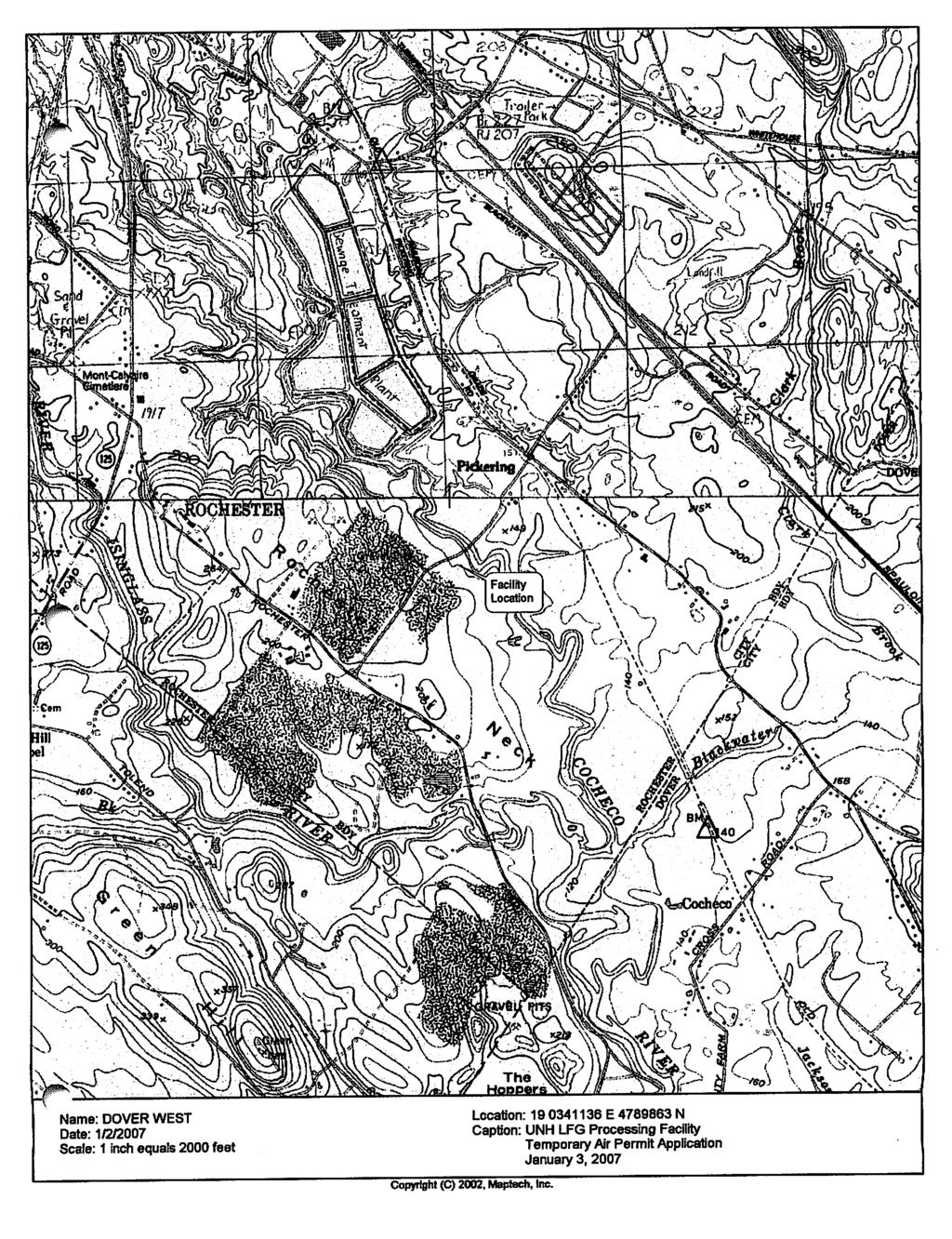
87
88
89
90 UNIVERSITY OF NEW HAMPSHIRE LANDFILL GAS PROCESSING FACILITY AIR EMISSIONS CALCULATIONS RECIPROCATING ENGINES (CAT 3520 x 2) Lbs per Capacity Tons per Full Output Capacity Emission Factor Hour Up Time Factor Year NOx 4466 bhp g/bhp-hr % 100% CO 4466 bhp g/bhp-hr % 100% VOC 4466 bhp g/bhp-hr % 100% SOx 4466 bhp g/bhp-hr % 100% 1.94 Particulate 4466 bhp g/bhp-hr % 100% 4.18 SUPPLEMENTAL TURBINE (Mercury 50) NOx mmbtu/hr lbs/mmbtu % 93% 3.17 CO mmbtu/hr lbs/mmbtu % 93% 3.80 VOC mmbtu/hr lbs/mmbtu % 93% 2.24 SOx mmbtu/hr lbs/mmbtu % 93% 0.26 Particulate mmbtu/hr lbs/mmbtu % 93% 7.25 THERMAL OXIDIZER NOx mmbtu/hr lbs/mmbtu % 95% 9.31 CO mmbtu/hr lbs/mmbtu % 95% 9.31 VOC mmbtu/hr lbs/mmbtu % 95% 8.60 SOx mmbtu/hr lbs/mmbtu % 95% 2.15 Particulate mmbtu/hr lbs/mmbtu % 95% 6.02 STANDBY AND SUPPLEMENTAL LFG FLARES Utility Flare 1 or 2 (as Supplemental) NOx mmbtu/hr lbs/mmbtu % 12% 3.88 CO mmbtu/hr lbs/mmbtu % 12% VOC mmbtu/hr lbs/mmbtu % 12% 3.88 SOx mmbtu/hr lbs/mmbtu % 12% 9.64 Particulate mmbtu/hr lbs/mmbtu % 12% 2.72 Utility Flare 1 (as Standby) NOx mmbtu/hr lbs/mmbtu 7.5 7% 100% 2.31 CO mmbtu/hr lbs/mmbtu % 100% 7.69 VOC mmbtu/hr lbs/mmbtu 7.5 7% 100% 2.31 SOx mmbtu/hr lbs/mmbtu % 100% 5.73 Particulate mmbtu/hr lbs/mmbtu 5.3 7% 100% 1.61 Utility Flare 2 (as Standby) NOx mmbtu/hr lbs/mmbtu 6.3 7% 100% 1.93 CO mmbtu/hr lbs/mmbtu % 100% 6.44 VOC mmbtu/hr lbs/mmbtu 6.3 7% 100% 1.93 SOx mmbtu/hr lbs/mmbtu % 100% 4.80 Particulate mmbtu/hr lbs/mmbtu 4.4 7% 100% 1.35 GRAND TOTAL NOx CO VOC SOx Particulate 23.14
91
92
93

94

95

96

97
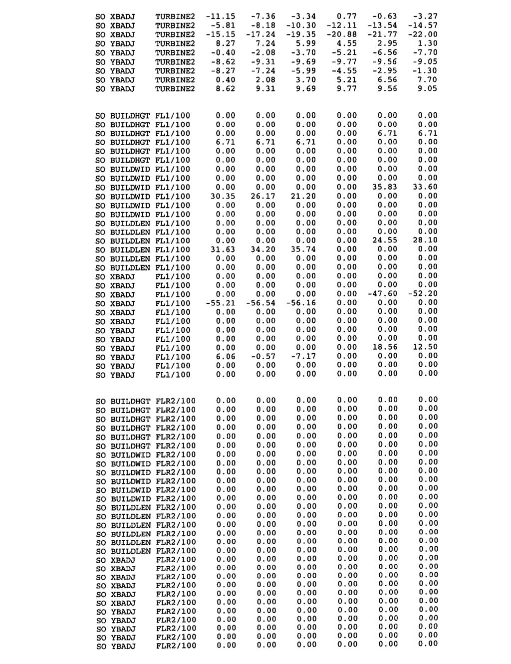
98

99

100

101

102

103
104

105

106
107
108

109

110
111

112
113
114
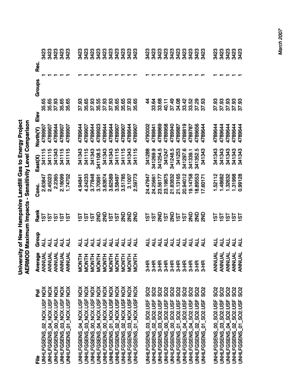
115

116

117

118
119

120
Michigan Department of Environmental Quality - Air Quality Division ADDITIONAL TECHNICAL INFORMATION FOR BOILERS
 Michigan Department of Environmental Quality - Air Quality Division ADDITIONAL TECHNICAL INFORMATION FOR BOILERS The following information will be used for the technical review of a permit to install application
State of the Art (SOTA) Manual for Stationary Gas Turbines
 Manual for Stationary Gas Turbines") State of the Art (SOTA) Manual for Stationary Gas Turbines Original Date: July 1997 Revision Date: November 1999 State of New Jersey Department of Environmental Protection Air Quality Permitting Program
State of the Art (SOTA) Manual for Stationary Gas Turbines Original Date: July 1997 Revision Date: November 1999 State of New Jersey Department of Environmental Protection Air Quality Permitting Program
PERMIT APPLICATION REVIEW SUMMARY
 PERMIT APPLICATION REVIEW SUMMARY New Hampshire Department of Environmental Services Air Resources Division P.O. Box 95, 29 Hazen Drive Concord, NH 03302-0095 Phone: 603-271-1370 Fax: 603-271-7053 AFS
FINAL DETERMINATION. To Grant a. Temporary Permit/Non-Attainment New Source Review Permit. For. Concord Steam Corporation.
 FINAL DETERMINATION To Grant a Temporary Permit/Non-Attainment New Source Review Permit For Concord Steam Corporation To Construct a 305 MMBtu/hr Biomass Boiler (Wood & Natural Gas), 2 Auxiliary Boilers
State of New Hampshire Department of Environmental Services Air Resources Division. Temporary Permit
 State of New Hampshire Department of Environmental Services Air Resources Division Temporary Permit Permit No: TP-0120 Date Issued: December 26, 2012 This certifies that: Northeast Utilities Public Service
PRIMARY OR ALTERNATIVE OPERATING SCENARIO
 EMISSION SOURCE (Fuel Combustion Source) Instructions for Form B2 Form B2 should be completed for all fuel combustion emission sources (e.g., generators, boilers, burn-off ovens, bakeon ovens, bakery ovens,
PERMIT APPLICATION REVIEW SUMMARY
 PERMIT APPLICATION REVIEW SUMMARY New Hampshire Department of Environmental Services Air Resources Division P.O. Box 95, 29 Hazen Drive Concord, NH 03302-0095 Phone: 603-271-1370 Fax: 603-271-7053 Phone
Clean Air Act Emission Limits
 1 Clean Air Act Emission Limits CAA Emission Limits Authority for and Origin of Limits Federally promulgated regulations (e.g. NSPS, NESHAP, or MACT) SIP requirements PSD and N/A NSR permits 2 NSPS 3 New
RELEASE POINT TYPE Enter or select one of the following stack/emission point release orientation: downward
 EMISSION SOURCE (Internal Combustion Engines) Instructions for Form B2-G Form B2-G should be completed for all generators. Make as many copies of the form as necessary. Attach all calculations and assumptions
BACT Determination Information
 UNDER PUBLIC REVIEW SMAQMD BACT CLEARINGHOUSE CATEGORY: LANDFILL GAS FLARE BACT Size: Minor Source BACT LANDFILL GAS FLARE BACT Determination Number: Permit Number: Equipment Description: Unit Size/Rating/Capacity:
Wyodak Power Plant. Chapter 6, Section 2 Construction Permit Application. Submitted to the Wyoming Air Quality Division And Prepared by
 Wyodak Power Plant Chapter 6, Section 2 Construction Permit Application Submitted to the Wyoming Air Quality Division And Prepared by 1407 West North Temple Salt Lake City, Utah 84116 March 2008 1.0 Introduction
1) ABSORPTION The removal of one or more selected components from a gas mixture by absorption is probably the most important operation in the control
 ABSORPTION The removal of one or more selected components from a gas mixture by absorption is probably the most important operation in the control") 1) ABSORPTION The removal of one or more selected components from a gas mixture by absorption is probably the most important operation in the control of gaseous pollutant emissions. Absorption is a process
1) ABSORPTION The removal of one or more selected components from a gas mixture by absorption is probably the most important operation in the control of gaseous pollutant emissions. Absorption is a process
BOILER/HEATER > 5 MMBTU BACT Size: MINOR SOURCE BACT BOILER. BACT Determination Information
 ACTIVE SMAQMD BACT CLEARINGHOUSE CATEGORY: BOILER/HEATER > 5 MMBTU BACT Size: MINOR SOURCE BACT BOILER BACT Determination Number: 157 BACT Determination Date: 6/19/2018 Equipment Information Permit Number:
MICHIGAN DEPARTMENT OF ENVIRONMENTAL QUALITY AIR QUALITY DIVISION. January 26, NEW SOURCE REVIEW PERMIT TO INSTALL No.
 MICHIGAN DEPARTMENT OF ENVIRONMENTAL QUALITY AIR QUALITY DIVISION January 26, 2005 NEW SOURCE REVIEW PERMIT TO INSTALL No. 307-04 ISSUED TO Nitro-Vac Heat Treat, Inc. LOCATED AT 23080 Dequindre Warren,
SWCAA Emission Inventory Instructions
 SWCAA Emission Inventory Instructions Why is an emission inventory required? Most of the emission inventory reporting requirements originated in Title 0 of the Code of Federal Regulations (0 CFR) Part
Tennessee Gas Pipeline Company, LLC Compressor Station Whites Creek Pike Page 1
 Tennessee Gas Pipeline Company, LLC Compressor Station 563 7650 Whites Creek Pike Page 1 Joelton, Tennessee Reviewed by: Blake McClain RE: Installation of two Solar Titan 250-30000S natural gas-fired turbines
TANK/PIPELINE DEGASSING SYSTEM BACT Size: Minor Source BACT THERMAL OXIDIZING UNIT - PORTABLE. BACT Determination Information
 UNDER PUBLIC REVIEW SMAQMD BACT CLEARINGHOUSE CATEGORY: TANK/PIPELINE DEGASSING SYSTEM BACT Size: Minor Source BACT THERMAL OXIDIZING UNIT - PORTABLE BACT Determination Number: 213 BACT Determination Date:
Naughton Power Plant. Chapter 6, Section 2 Construction Permit Application. Submitted to the Wyoming Air Quality Division And Prepared by
 Naughton Power Plant Chapter 6, Section 2 Construction Permit Application Submitted to the Wyoming Air Quality Division And Prepared by 1407 West North Temple Salt Lake City, Utah 84116 March 2008 1.0
STATEMENT OF BASIS for NEWARK BAY COGENERATION PARTNERSHIP L.P.
 I. FACILITY INFORMATION Newark Bay Cogeneration Partnership L.P. is located at 414-514 Avenue P, Newark, New Jersey, Essex County and consists of a 120-megawatt cogeneration plant. The facility is owned
Engineering Summary UNH Cogeneration Project Fall 2003, Durham, NH
 1 Engineering Summary UNH Cogeneration Project Fall 2003, Durham, NH Application #: FY04-0148 AFS #: 3301700009 County: Strafford Engineer: Laughton Date: Late Fall 2003 The University of New Hampshire
SUNY Westchester Community College Air Emissions Permit Program Latest Revision Date January 2, 2016 Previous Revision Date June 12, 2015.
 SUNY Westchester Community College Air Emissions Permit Program Latest Revision Date January 2, 2016 Previous Revision Date June 12, 2015 Air Emissions Permit Program Contents I. Air Permitting Introduction
"LIST AND CRITERIA" INDEX INTRODUCTION Section 1 - General Application Information... 5
 "LIST AND CRITERIA" INFORMATION REQUIRED OF APPLICANTS SEEKING A PERMIT FROM THE SACRAMENTO AIR QUALITY MANAGEMENT DISTRICT Adopted March, 1985 (Amended 6-7-94, 01-11-96, 08-01-96) INDEX INTRODUCTION...
SACRAMENTO METROPOLITAN AIR QUALITY MANAGEMENT DISTRICT EXPEDITED BARCT IMPLEMENTATION SCHEDULE FOR ASSEMBLY BILL 617.
 SACRAMENTO METROPOLITAN AIR QUALITY MANAGEMENT DISTRICT EXPEDITED BARCT IMPLEMENTATION SCHEDULE FOR ASSEMBLY BILL 617 Prepared by: Approved by: Kevin J. Williams, Ph.D. Program Supervisor Mark Loutzenhiser
Stakeholder Meeting Installed Capacity Demand Curves
 Stakeholder Meeting Installed Capacity Demand Curves Debra Richert William Frazier Tom Vivenzio December 16, 2015 New York Independent System Operator A World of Solutions TM 0 Agenda 1. Tariff Requirements
PUBLIC PARTICIPATION DOCUMENTS For DCP Midstream, LP Hamilton Township, Michigan
 STATE OF MICHIGAN Rick Snyder, Governor DEPARTMENT OF ENVIRONMENTAL QUALITY AIR QUALITY DIVISION CONSTITUTION HALL 525 WEST ALLEGAN STREET P.O. BOX 30260 LANSING, MICHIGAN 48909-7760 www.michigan.gov/air
BEST AVAILABLE CONTROL TECHNOLOGY & TOXIC BEST AVAILABLE CONTROL TECHNOLOGY DETERMINATION
 777 12 th Street, Third Floor Sacramento, CA 95814 BEST AVAILABLE CONTROL TECHNOLOGY & TOXIC BEST AVAILABLE CONTROL TECHNOLOGY DETERMINATION DETERMINATION NO.: 145 Category/General Equip Description: Equipment
BACT Determination Information
 UNDER PUBLIC REVIEW SMAQMD BACT CLEARINGHOUSE CATEGORY: MISCELLANEOUS BACT Size: Tortilla Oven 500 F OVEN BACT Determination Number: Permit Number: Equipment Description: Unit Size/Rating/Capacity: Equipment
BACT Determination Information
 ACTIVE SMAQMD BACT CLEARINGHOUSE CATEGORY: MISCELLANEOUS BACT Size: Tortilla Oven 500 F OVEN BACT Determination Number: Permit Number: Equipment Description: Unit Size/Rating/Capacity: Equipment Location:
MICHIGAN DEPARTMENT OF ENVIRONMENTAL QUALITY AIR QUALITY DIVISION. November 8, PERMIT TO INSTALL No A
 MICHIGAN DEPARTMENT OF ENVIRONMENTAL QUALITY AIR QUALITY DIVISION November 8, 2007 PERMIT TO INSTALL No. 541-88A ISSUED TO Clariant Corporation Masterbatches Division LOCATED AT 926 Elliott Road Albion,
MICHIGAN DEPARTMENT OF ENVIRONMENTAL QUALITY AIR QUALITY DIVISION. March 17, 2004 NEW SOURCE REVIEW PERMIT TO INSTALL
 MICHIGAN DEPARTMENT OF ENVIRONMENTAL QUALITY AIR QUALITY DIVISION March 17, 2004 NEW SOURCE REVIEW PERMIT TO INSTALL 220-03 ISSUED TO Federal Mogul Powertrain, Inc. LOCATED AT 560 Avis Drive Ann Arbor,
PERMIT APPLICATION REVIEW SUMMARY
 PERMIT APPLICATION REVIEW SUMMARY New Hampshire Department of Environmental Services Air Resources Division P.O. Box 95, 29 Hazen Drive Concord, NH 03302-0095 Phone: 603-271-1370 Fax: 603-271-7053 AFS
State of New Hampshire Department of Environmental Services Air Resources Division. Temporary Permit
 State of New Hampshire Department of Environmental Services Air Resources Division Temporary Permit Permit No: FP-T-0152 Date Issued: July 18, 2007 Administrative Permit Amendment: June 11, 2008 This certifies
CEE 452/652. Week 14, Lecture 1 NOx control. Dr. Dave DuBois Division of Atmospheric Sciences, Desert Research Institute
 CEE 45/65 Week 14, Lecture 1 NOx control Dr. Dave DuBois Division of Atmospheric Sciences, Desert Research Institute Today s topics Today s topic: NOx control Read chapter 16 Presentations on Nov 9 and
ENGINEERING CALCULATION SHEET AIR RESOURCES DIVISION
 SIC Code: 4911 (Energy Production) DATE: 02/06/2008 Page 1 of 5 DATE APPLICATION RECEIVED: December 14, 2007 (Application # FY07-0259) FACILITY DESCRIPTION Pinetree Power-Tamworth, Inc. (the Permittee)
Notice of Intent Application
 Utah Power Plant Units 1, 2, and 3 Repowering Notice of Intent Application Submitted to Utah Division of Air Quality Prepared for Kennecott Utah Copper LLC Prepared by: December 2010 Notice of Intent
PERMIT APPLICATION REVIEW SUMMARY
 PERMIT APPLICATION REVIEW SUMMARY New Hampshire Department of Environmental Services Air Resources Division P.O. Box 95, 29 Hazen Drive Concord, NH 03302-0095 Phone: 603-271-1370 Fax: 603-271-7053 AFS
State Of The Art (SOTA) Manual For Non-Hazardous Onsite Remediation Processes
 Manual For Non-Hazardous Onsite Remediation Processes") State Of The Art (SOTA) Manual For Non-Hazardous Onsite Remediation Processes July 1997 State of New Jersey Department of Environmental Protection Air Quality Permitting Program State of the Art (SOTA)
State Of The Art (SOTA) Manual For Non-Hazardous Onsite Remediation Processes July 1997 State of New Jersey Department of Environmental Protection Air Quality Permitting Program State of the Art (SOTA)
PERMIT TO INSTALL. Table of Contents
 Permit No. 134-16 Page 1 of 9 PERMIT TO INSTALL Table of Contents Section Page Alphabetical Listing of Common Abbreviations / Acronyms... 2 General Conditions... 3 Special Conditions... 5 Emission Unit
PERMIT TO INSTALL. Table of Contents
 Permit No. 77-17 Page 1 of 7 PERMIT TO INSTALL Table of Contents Section Page Alphabetical Listing of Common Abbreviations / Acronyms... 2 General Conditions... 3 Special Conditions... 5 Emission Unit
2. How can the University have an expansion of the Cogeneration Facility without an increase in the amount of coal used?
 Responses to Questions Raised at the November 9, 2005 Public Hearing on the University of North Carolina at Chapel Hill s Special Use Permit Modification Request 1. What is the nature of the surveying
Arkansas Department of pollution Control and Ecology Division of Air Pollution Control. Summary Report Relative to Permit Application
 ----- Vr%/tXJ Arkansas Department of pollution Control and Ecology Division of Air Pollution Control Summary Report Relative to Permit Application Submitted By: Nekoosa Papers, Inc. Ashdown, Arkansas (Little
Table of Contents. (a) APPLICABILITY... 1 (b) EXEMPTIONS... 1 (c) DEFINITIONS... 1 (d) STANDARDS... 2
 APPLICABILITY... 1 (b) EXEMPTIONS... 1 (c) DEFINITIONS... 1 (d) STANDARDS... 2") RULE 20.4 NEW SOURCE REVIEW PORTABLE EMISSION UNITS (ADOPTED AND EFFECTIVE 5/17/94) (REV. ADOPTED AND EFFECTIVE 12/17/97) (REV. ADOPTED 11/4/98; EFFECTIVE 12/17/98) (REV. ADOPTED AND EFFECTIVE 4/27/16)
RULE 20.4 NEW SOURCE REVIEW PORTABLE EMISSION UNITS (ADOPTED AND EFFECTIVE 5/17/94) (REV. ADOPTED AND EFFECTIVE 12/17/97) (REV. ADOPTED 11/4/98; EFFECTIVE 12/17/98) (REV. ADOPTED AND EFFECTIVE 4/27/16)
TECHNICAL FACT SHEET June 19, 2018
 New Covert Generating Company, LLC Page 1 Purpose and Summary TECHNICAL FACT SHEET June 19, 2018 The Michigan Department of Environmental Quality (MDEQ), Air Quality Division (AQD), is proposing to act
Guide to Low-Emission Boiler and Combustion Equipment Selection
 ORNL/TM-2002/19 Guide to Low-Emission Boiler and Combustion Equipment Selection C. B. Oland ORNL/TM-2002/19 GUIDE TO LOW-EMISSION BOILER AND COMBUSTION EQUIPMENT SELECTION C. B. Oland Date Published: April
PART C - POLICY AND PROCEDURES FOR NON-MAJOR POLLUTING FACILITIES
 PART C - POLICY AND PROCEDURES FOR NON-MAJOR POLLUTING FACILITIES BACT GUIDELINES PART C 30 DECEMBER 2016 Chapter 1 - How Is MSBACT Determined for Minor Polluting Facilities? This chapter explains the
Air Permi>ng: A Major Piece of the Puzzle or Trying to Keep All of
 Air Permi>ng: A Major Piece of the Puzzle or Trying to Keep All of the Balls in the Air Insert then choose Picture select your picture. Right click your picture and Send to back. The world s leading sustainability
STATEMENT OF BASIS Mannington Mills, Inc. dba Mannington Wood Floors Epes, Sumter County, Alabama Facility/Permit No
 STATEMENT OF BASIS Mannington Mills, Inc. dba Mannington Wood Floors Epes, Sumter County, Alabama Facility/Permit No. 412-0011 This draft initial Title V Major Source Operating Permit (MSOP) is issued
BEST AVAILABLE CONTROL TECHNOLOGY DETERMINATION
 777 12 th Street, Third Floor Sacramento, CA 95814 BEST AVAILABLE CONTROL TECHNOLOGY DETERMINATION Category/General Equip Description: Equipment Specific Description: Equipment Size/Rating: DETERMINATION
AIR REGULATION IN SOUTH CAROLINA 3 JUNE 2016
 AIR REGULATION IN SOUTH CAROLINA Presented by Phil Conner 3 JUNE 2016 pconner@nexsenpruet.com SCDHEC s Authority for Administering Air Quality Regulations South Carolina Pollution Control Act (The PCA
Table of Contents. (a) APPLICABILITY... 1 (b) EXEMPTIONS... 1 (c) DEFINITIONS... 1 (d) STANDARDS... 2
 APPLICABILITY... 1 (b) EXEMPTIONS... 1 (c) DEFINITIONS... 1 (d) STANDARDS... 2") RULE 20.4 NEW SOURCE REVIEW PORTABLE EMISSION UNITS (ADOPTED AND EFFECTIVE 5/17/94) (REV. ADOPTED AND EFFECTIVE 12/17/97) (REV. ADOPTED 11/4/98; EFFECTIVE 12/17/98) (REV. ADOPTED AND EFFECTIVE 4/27/16)
RULE 20.4 NEW SOURCE REVIEW PORTABLE EMISSION UNITS (ADOPTED AND EFFECTIVE 5/17/94) (REV. ADOPTED AND EFFECTIVE 12/17/97) (REV. ADOPTED 11/4/98; EFFECTIVE 12/17/98) (REV. ADOPTED AND EFFECTIVE 4/27/16)
STATEMENT OF BASIS. Cheney Lime & Cement Company Landmark Plant Alabaster, Alabama Shelby County Facility No
 STATEMENT OF BASIS Cheney Lime & Cement Company Landmark Plant Alabaster, Alabama Shelby County Facility No. 411-0019 This proposed Title V Major Source Operating Permit (MSOP) renewal is issued under
MICHIGAN DEPARTMENT OF ENVIRONMENTAL QUALITY AIR QUALITY DIVISION. February 3, NEW SOURCE REVIEW PERMIT TO INSTALL No.
 MICHIGAN DEPARTMENT OF ENVIRONMENTAL QUALITY AIR QUALITY DIVISION February 3, 2005 NEW SOURCE REVIEW PERMIT TO INSTALL No. 605-89B ISSUED TO Medtronic Biomedicus, Inc. LOCATED AT 520 Watson Street SW Grand
Emergency Engine and Turbine Requirements
 1.0 Purpose and Applicability 1.1 The purpose of these guidelines is to identify the processes and requirements that must be followed to ensure compliance with the Massachusetts Department of Environmental
GOVERNMENT of PUERTO RICO OFFICE OF THE GOVERNOR ENVIRONMENTAL QUALITY BOARD
 GOVERNMENT of PUERTO RICO OFFICE OF THE GOVERNOR ENVIRONMENTAL QUALITY BOARD Air Quality Area STATEMENT OF BASIS Title V Initial Permit The Puerto Rico Environmental Quality Board (EQB) is issuing a draft
Marquette General Health System December 11, 2001 Permit No B Page 1 of 8. Table of Contents
 Permit No. 252-93B Page 1 of 8 Section Table of Contents Page Alphabetical Listing of Common Abbreviations/Acronyms... 2 General Conditions... 3 Emission Unit Identification... 5 Flexible Group Identification...
A. The New Hampshire Code of Administrative Rules Env-A 100 et seq., New Hampshire Rules Governing the Control of Air Pollution; and
 State of New Hampshire Department of Environmental Services Air Resources Division State Permit to Operate Facility ID No: 3301100173 Permit No: FP-S-0193 County: Hillsborough Date Issued: July 12, 2004
PERMIT TO INSTALL. Table of Contents
 Permit No. 149-18 Page 1 of 7 PERMIT TO INSTALL Table of Contents Section Page Alphabetical Listing of Common Abbreviations / Acronyms... 2 General Conditions... 3 Special Conditions... 5 Emission Unit
Atmospheric Disperssion
 Atmospheric Disperssion Dispersion is the process by which contaminants move through the air and a plume spreads over a large area, thus reducing the concentration of the pollutants it contains. Atmospheric
MICHIGAN DEPARTMENT OF ENVIRONMENTAL QUALITY AIR QUALITY DIVISION. June 16, 2016 PERMIT TO INSTALL 71-03C ISSUED TO JBS USA
 MICHIGAN DEPARTMENT OF ENVIRONMENTAL QUALITY AIR QUALITY DIVISION June 16, 2016 PERMIT TO INSTALL 71-03C ISSUED TO JBS USA LOCATED AT 11 11 th Street Plainwell, Michigan IN THE COUNTY OF Allegan STATE
United States Environmental Protection Agency, Region 9. Air Division. Technical Support Document. for. EPA s Notice of Proposed Rulemaking.
 United States Environmental Protection Agency, Region 9 Air Division Technical Support Document for EPA s Notice of Proposed Rulemaking for the California State Implementation Plan San Joaquin Valley Unified
APPENDIX C SCAQMD PERMIT APPLICATION
 APPENDIX C SCAQMD PERMIT APPLICATION Application to the South Coast Air Quality Management District for a Permit to Construct and Permit to Operate for the Natural Gas-Fired Long Beach Emergency Repowering
FACILITY PROFILE. New Brunswick Power Corporation for the Belledune Thermal Generating Station
 FACILITY PROFILE New Brunswick Power Corporation for the Belledune Thermal Generating Station Prepared by: Industrial Processes Section, Impact Management Branch Department of Environment and Local Government
Demonstration of Fuel Cells to Recover Energy from Landfill Gas Phase III. Demonstration Tests, and Phase IV. Guidelines and Recommendations
 United States National Risk Management Environmental Protection Research Laboratory Agency Cincinnati, OH 45268 Research and Development EPA/600/SR-98/002 March 1998 Project Summary Demonstration of Fuel
UNH ECOLine: Tapping Landfill Gas for Campus Energy Paul Chamberlin
 UNH ECOLine: Tapping Landfill Gas for Campus Energy Paul Chamberlin Assistant Vice President University of New Hampshire University of New Hampshire Environmental Business Council Renewable Energy at Closed
Serving Two Masters; Understanding Texas and EPA Permitting Programs
 Serving Two Masters; Understanding Texas and EPA Permitting Programs 4C Health, Safety, and Environmental Conference April 3 rd, 2018 Texas and EPA Permitting Programs 2 Quick History of Air Permitting
Tajiguas Resource Recovery Project
 Tajiguas Resource Recovery Project 2018 CAPCOA Engineering Symposium Kevin Brown Air Quality Engineer III Santa Barbara County Air Pollution Control District October 30, 2018 1 Presentation Overview Background
MICHIGAN DEPARTMENT OF ENVIRONMENTAL QUALITY AIR QUALITY DIVISION. October 24, 2005 PERMIT TO INSTALL
 MICHIGAN DEPARTMENT OF ENVIRONMENTAL QUALITY AIR QUALITY DIVISION October 24, 2005 PERMIT TO INSTALL 263-05 ISSUED TO Superior Vault & Cremation Services LOCATED AT 345 East Mahoney Merrill, Michigan IN
Air Regulations Impacting the Pipeline Industry
 Air Regulations Impacting the Pipeline Industry Presented by Jim McCarthy innovative environmental solutions, Inc. 1 Agenda Overview of federal air regulations that drive requirements for pipeline facilities
Michigan Department of Environmental Quality Air Quality Division RENEWABLE OPERATING PERMIT STAFF REPORT
 State Registration Number Michigan Department of Environmental Quality Air Quality Division RENEWABLE OPERATING PERMIT ROP Number B8337 STAFF REPORT MI-ROP-B8337-2015 ANR PIPELINE COMPANY - MUTTONVILLE
Statement of Basis. Daikin America, Inc. Morgan County Decatur, Alabama
 Statement of Basis Daikin America, Inc. Morgan County Decatur, Alabama 712-0061 Daikin America, Inc. ( Daikin ) has applied for renewal of Major Source Operating Permit No. 712-0061. This proposed Title
BEST AVAILABLE CONTROL TECHNOLOGY & TOXIC BEST AVAILABLE CONTROL TECHNOLOGY DETERMINATION
 777 12 th Street, Third Floor Sacramento, CA 95814 BEST AVAILABLE CONTROL TECHNOLOGY & TOXIC BEST AVAILABLE CONTROL TECHNOLOGY DETERMINATION Category/General Equip Description: Equipment Specific Description:
RECOMMENDED CPCN CONDITIONS CASE NO CATOCTIN POWER, LLC
 RECOMMENDED CPCN CONDITIONS CASE NO. 8997 CATOCTIN POWER, LLC General 1. Except as otherwise provided for in the following provisions, the application for the Certificate of Public Convenience and Necessity
ASA Bloomingburg, LLC. Air permit-to-install (PTI) number Public Hearing Date April 18, 2006 Comment Period End Date April 25, 2006
 number Public Hearing Date April 18, 2006 Comment Period End Date April 25, 2006") ASA Bloomingburg, LLC Air permit-to-install (PTI) number 01-01306 Public Hearing Date April 18, 2006 Comment Period End Date April 25, 2006 Summary of Comments and Ohio EPA Responses August 2006 Introduction
ASA Bloomingburg, LLC Air permit-to-install (PTI) number 01-01306 Public Hearing Date April 18, 2006 Comment Period End Date April 25, 2006 Summary of Comments and Ohio EPA Responses August 2006 Introduction
TECHNICAL FACT SHEET September 24, 2018
 Copperwood Resources, Inc. Page 1 Purpose and Summary TECHNICAL FACT SHEET September 24, 2018 The Michigan Department of Environmental Quality (MDEQ), Air Quality Division (AQD), is proposing to act on
Southwest Clean Air Agency NE 99 th St, Suite 1294, Vancouver, WA 98682
 Source Test Guidance Test plans are required to be submitted to SWCAA prior to testing. Generally the plans must be submitted 2 weeks prior to testing but may be different based on individual facility
San Joaquin Valley Unified Air Pollution Control District. Best Performance Standard (BPS) x.x.xx
 x.x.xx") San Joaquin Valley Unified Air Pollution Control District Best Performance Standard (BPS) x.x.xx Class Category VOC Control/Gas Disposal Oil and Gas Production, Processing, and Refining 1) -Incineration
San Joaquin Valley Unified Air Pollution Control District Best Performance Standard (BPS) x.x.xx Class Category VOC Control/Gas Disposal Oil and Gas Production, Processing, and Refining 1) -Incineration
Your Presenters: Scott Bayon / Director of Sales Anguil Environmental Systems Brian Kunkle / Director of Systems Sales Verantis Environmental
 Your Presenters: Scott Bayon / Director of Sales Anguil Environmental Systems Brian Kunkle / Director of Systems Sales Verantis Environmental Solutions Group. Status and Certificate Quiz PDH Overview Today
Progress Report Study Approach and Assumptions
 Progress Report Study Approach and Assumptions Presentation to NYISO Installed Capacity Working Group Christopher D. Ungate, Senior Principal Consultant March 1, 2013 Topics Update on technology screening
Palos Verdes Landfill Proposed to-energy Facility Replacement
 Palos Verdes Landfill Proposed Gas-to to-energy Facility Replacement This presentation discusses the proposed project that replaces the existing Gas-to- Energy Facility at the closed Palos Verdes Landfill
CHP, Waste Heat & District Energy
 600 500 400 300 200 100 0 Electric Cooling T/E Ratio Electricity Consumption & Cooling T/E Ratio 0.50 0.45 0.40 0.35 0.30 0.25 0.20 0.15 0.10 0.05 0.00 CHP, Waste Heat & District Energy Module 5: Biomass
Biomass Emissions Permitting in Pennsylvania
 Biomass Emissions Permitting in Pennsylvania Penn State Bioenergy Emissions and Health Short Course March 22, 2012 1 John Slade jslade@all4inc.com Meghan Schulz mschulz@all4inc.com Agenda Basics: Regulated
Callidus Oxidizer Systems. Thermal and Catalytic Oxidizer Systems
 Callidus Oxidizer Systems Thermal and Catalytic Oxidizer Systems Meet the Thermal Oxidizer Experts Wide Range of Applications Honeywell UOP Callidus is an industry leader in environmental combustion technology.
MICHIGAN DEPARTMENT OF ENVIRONMENTAL QUALITY AIR QUALITY DIVISION. November 15, 2013 PERMIT TO INSTALL
 MICHIGAN DEPARTMENT OF ENVIRONMENTAL QUALITY AIR QUALITY DIVISION November 15, 2013 PERMIT TO INSTALL 143-13 ISSUED TO Newberry Correctional Facility LOCATED AT 13747 East County Road 428 Newberry, Michigan
PERMITTEE Seminole Electric Cooperative, Inc North Dale Mabry Highway Tampa, FL 33618
 PERMITTEE 16313 North Dale Mabry Highway Tampa, FL 33618 Authorized Representative: James R. Frauen, Project Director Air Permit No. 1070025-004-AC Units 1-2 Pollution Controls Upgrade Facility ID No.
MICHIGAN DEPARTMENT OF ENVIRONMENTAL QUALITY AIR QUALITY DIVISION. May 14, 2015 PERMIT TO INSTALL ISSUED TO Cherished Memories Pet Cremation
 MICHIGAN DEPARTMENT OF ENVIRONMENTAL QUALITY AIR QUALITY DIVISION May 14, 2015 PERMIT TO INSTALL 60-15 ISSUED TO Cherished Memories Pet Cremation LOCATED AT 15 4 th Street Sand Lake, Michigan IN THE COUNTY
ALLEGHENY COUNTY HEALTH DEPARTMENT AIR QUALITY PROGRAM
 ALLEGHENY COUNTY HEALTH DEPARTMENT AIR QUALITY PROGRAM October 5, 2011 SUBJECT: Renewal Title V Operating Permit Application Chambers Development Company, Inc. - Monroeville Landfill 600 Thomas Street
AIR PERMITTING CASE STUDY: HARVARD S CHP EXPANSION
 Michael X. Macrae, PhD, Harvard University Environmental Health & Safety A.J. Jablonowski, PE, Epsilon Associates AIR PERMITTING CASE STUDY: HARVARD S CHP EXPANSION 1 Overview Harvard University is expanding
PUBLIC PARTICIPATION DOCUMENTS For Holland Board of Public Works Holland, Michigan
 STATE OF MICHIGAN Rick Snyder, Governor DEPARTMENT OF ENVIRONMENTAL QUALITY AIR QUALITY DIVISION CONSTITUTION HALL 525 WEST ALLEGAN STREET P.O. BOX 30260 LANSING, MICHIGAN 48909-7760 www.michigan.gov/air
502(b)(10) Permit for Part 70 Source
(10) Permit for Part 70 Source") 502(b)(10) Permit for Part 70 Source Permit Attachment No.: 2075-139-0002-V-03-1 Effective Date: November 9, 2015 Facility Name: Mailing Address: Parent/Holding Company: 862 West Ridge Road Gainesville,
502(b)(10) Permit for Part 70 Source Permit Attachment No.: 2075-139-0002-V-03-1 Effective Date: November 9, 2015 Facility Name: Mailing Address: Parent/Holding Company: 862 West Ridge Road Gainesville,
RULE Federally Enforceable Limits on Potential to Emit - Adopted 1/25/96, Amended 1/12/12 (Effective 3/8/12)
") RULE 201.3 Federally Enforceable Limits on Potential to Emit - Adopted 1/25/96, Amended 1/12/12 (Effective 3/8/12) I. Purpose The purpose of this Rule is to allow relatively small sources of air pollution
RULE 201.3 Federally Enforceable Limits on Potential to Emit - Adopted 1/25/96, Amended 1/12/12 (Effective 3/8/12) I. Purpose The purpose of this Rule is to allow relatively small sources of air pollution
MICHIGAN DEPARTMENT OF ENVIRONMENTAL QUALITY AIR QUALITY DIVISION. August 22, 2017 REVISED September 27, 2017 PERMIT TO INSTALL 99-17
 MICHIGAN DEPARTMENT OF ENVIRONMENTAL QUALITY AIR QUALITY DIVISION August 22, 2017 REVISED September 27, 2017 PERMIT TO INSTALL 99-17 ISSUED TO Michigan State University LOCATED AT 736 Wilson Road East
Technology Overview. Renewable Natural Gasification - RNG: How It Works:
 Technology Overview Renewable Natural Gasification - RNG: RNG is an advanced thermal conversion technology that uses an innovative and proprietary process to convert organic matter into a high-quality,
Biomass Boiler Emission Abatement Technologies. Simon Wakefield
 Biomass Boiler Emission Abatement Technologies Simon Wakefield simon.wakefield@hwenergy.co.uk About Us Established in 2003 Specialise only in biomass heating Team of 50 staff Design & engineering led company
New 2015 Ozone Standard and Implications. July 2016
 New 2015 Ozone Standard and Implications July 2016 What is Ozone? Ground level ozone is formed from the mixture of sunlight, NOx and VOC. 2 Effects of Ground Level Ozone 3 Effects of Ground Level Ozone
Update on ICI Boiler MACT
 Update on ICI Boiler MACT Bruce Hedman March 5, 2013 Clean Air Acts Standards for Boilers and Incinerators On December 20, 2012, EPA finalized a specific set of adjustments to March 2011 Clean Air Act
ADEQ OPERATING AIR PERMIT
 ADEQ OPERATING AIR PERMIT Pursuant to the Regulations of the Arkansas Operating Air Permit Program, Regulation #26: IS ISSUED TO: Columbian Chemicals Company 713 Industrial Park Road El Dorado, AR 71730-6623
Mailing Instructions and Information:
 NEW JERSEY DEPARTMENT NEW JERSEY DEPARTMENT OF ENVIRONMENTAL PROTECTION AIR QUALITY PERMITTING GENERAL PERMIT REGISTRATION FORM EMERGENCY GENERATOR(S) FIRST REVISION - OPERATIVE FEBRUARY 5, 2007 SECTION
Mailing Instructions and Information:
 NEW JERSEY DEPARTMENT OF ENVIRONMENTAL PROTECTION AIR QUALITY PERMITTING GENERAL PERMIT REGISTRATION FORM FOR RESEARCH AND DEVELOPMENT SECTION A: FACILITY PROFILE Facility ID Number SECTION B: REASON FOR