SIMPACK - MODEL DEVELOPMENT PACKAGE FOR POWER PLANTS
|
|
|
- Elfrieda Goodman
- 5 years ago
- Views:
Transcription
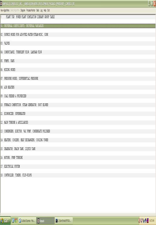
1 SIMPACK - MODEL DEVELOPMENT PACKAGE FOR POWER PLANTS 1.0 OVERVIEW SIMPACK is a totally integrated set of simulation software development modules for power plants. It is template based modeling tool and used by simulation engineers to configure, test, and document dynamic process simulation programs. These programs represent the power plant and are used in the operator training simulator. SIMPACK package consists of the following sections: Simulation Database Model Executive Process Algorithms Library Process Algorithms Coefficient Calculation Library Thermodynamic Property Algorithms Library General Algorithms Library Template based Model Configuration Automatic Calculation of Coefficients Interactive Process Monitor and Debugger User Manual 2.0 SIMULATION DATABASE This is a pre-defined Structure or Common Storage area designed for access by all programs that formulate the Operator Training Simulator. The nomenclature used in defining the symbols is based on standard engineering practice. The symbols are generally one or two-dimensional arrays, defined by the following groups: Model Executive Variables Instructor Inputs Instrumentation Input/output Variables Control Variables Logic Variables Process Variables (flow, pressure, enthalpy, temperature, composition, etc.) for condenser, feedwater heater, deaerator, steam drum, superheater, coal pulverizer, combustion, pump, fan, turbine stage, motor, valve, etc. Coefficients for all of the above groups Time derivatives of process variables Execution flags for all time derivatives
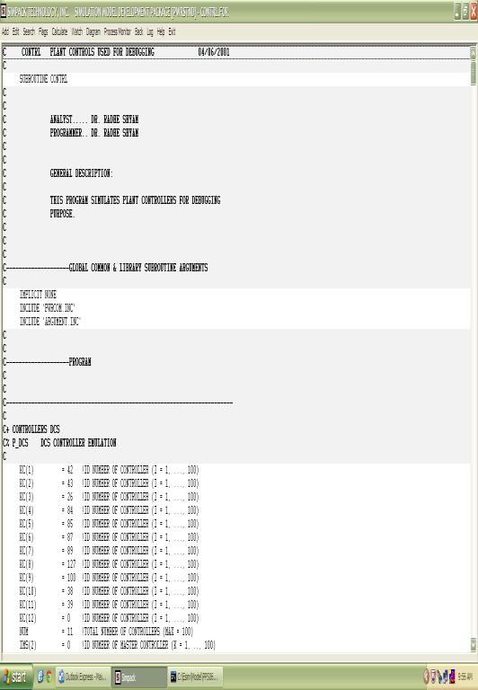
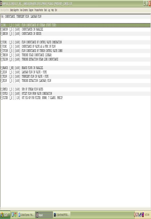
2 3.0 MODEL EXECUTIVE The Model Executive is the main program which executes the simulation model of the plant. The execution cycle is synchronized to represent real time. This program also interacts with the Instructor and Controls Programs. Additional features of this program include faster than and slower than real time execution upon request by the Instructor, suspending the model execution upon request by the Instructor, stepping the model one cycle at a time upon request by the Simulation Engineer during testing, and initializing the Database at the start of the simulation session. 4.0 PROCESS ALGORITHMS LIBRARY This Library consists of the building blocks for the plant. Each algorithm simulates an equipment, such as condenser, feedwater heater, deaerator, steam drum, turbine stage, coal pulverizer, rotary air heater, pump, fan, valve, etc. The mathematical models in the Algorithms consist of time-based differential equations, representing dynamic heat balance, mass balance, steam-water equilibrium, and engineering correlations, where applicable. Each Algorithm has been tested thoroughly for proper responses for the complete range of operations, and numerical stability. The error-free Algorithm is then added to the Library. The following Algorithms are included in this Library: Sources (air, water, steam, coal, fuel oil, fuel gas) Sink Air heaters (2-zone rotary, 3-zone rotary) Condensers (main, gland steam) Feedwater Heater, Drain cooler, Heat Exchanger Steam drum, Deaerator, Drain Tank Waterwalls (natural circulation, forced circulation, once-through) Superheater, Economizer Combustion Coal Pulverizer Steam Turbine Stage Gas Turbine Compressor Turbine Supervisory (bearing temp., vibration, eccentricity, diff. expansion) Electrical Generator Pumps (options include centrifugal, and reciprocating) Fans Steam Jet Air Ejector Valves (control, on/off, motor-operated, safety, etc.) Mixing nodes Flow Conductances (options include parallel, and series) Pipe flow (options include laminar, and turbulent) Pressure nodes (options include single node, and multiple node matrix)
3 Description of Major Algorithms CONDENSER This algorithm simulates a condenser, which is a tank containing cooling water tubes. Streams of water and steam are inputs to the condenser. The mixture is assumed to condense over the cooling water tubes. The resulting condensate is accumulated in the tank and is taken out by the connected pumps. Non-condensable gas (air) is also considered as input by virtue of inlet steam and leak malfunction. The air is removed by vacuum pumps, or steam jet ejectors. Unsteady-state heat balance on the vapor envelope gives the enthalpy of liquid that is assumed to be in equilibrium with the vapor at saturated conditions. Vapor pressure is then calculated as a function of this enthalpy from the available library of steam-water thermodynamic functions. Similarly, heat balance on the condensate gives the enthalpy. The temperature and density are then calculated from thermodynamic relationships. Mass balance on the condensate gives the liquid hold-up. Level is calculated as function of mass, density, and cross-sectional area of the tank Heat balance on the cooling tubes results in the calculation of the outlet cooling water temperature. Effects on malfunctions, such as cooling water tube fouling are included in the model. This malfunction results in loss of cooling and consequently higher pressure. SINGLE-PHASE HEAT EXCHAGER This algorithm simulates a shell-and-tube heat exchanger in which heat transfer takes place between two single-phase fluids. Unsteady-state heat balance is performed on each side, which results in the outlet temperatures of the tube side fluid and the shell side fluid. The heat balance equation involves the mass flow rate, the heat capacity, the inlet and outlet temperatures, and the mass hold-up. The heat transfer coefficient is assumed to be a function of flow rate. The rate of heat transfer is calculated as function of log mean temperature difference. Malfunctions, such as tube leak and tube fouling are included as part of the model. DEAERATOR This algorithm simulates a deaerator, which is a tank with inlet streams of water and steam. The mixture is flashed at vapor-liquid equilibrium conditions. The resulting condensate is accumulated in the tank and is taken out by the connected pumps. Unsteady-state heat balance on the vapor envelope gives the enthalpy of liquid that is assumed to be in equilibrium with the vapor at saturated conditions. Vapor pressure is then calculated as a function of this enthalpy from the available library of steam-water thermodynamic functions. Similarly, heat balance on the condensate gives the enthalpy. The temperature and density are then calculated from thermodynamic relationships. Mass balance on the condensate gives the liquid hold-up. Level is calculated as function of mass, density, and cross-sectional area of the tank.
4 STEAM DRUM This algorithm simulates a steam drum, which receives a mixture of steam and water from the evaporator. The mixture is assumed to be at saturated conditions, and the steam and water are completely separated in the drum. The vapor pressure is calculated by performing mass balance on the vapor envelope. The steam outlet may discharges to the atmosphere through a vent passed through the Superheater during normal operation. Heat balance is performed on the liquid pool which receives saturated liquid from the evaporator, and feedwater from the economizer. The liquid is discharged into the evaporator and the blowdown line. The heat balance gives the enthalpy of the liquid. Temperature is then calculated from enthalpy and vapor pressure, using thermodynamic property relationships. Mass balance on the liquid pool provides the level (density and cross-sectional area is used). Drum metal temperatures are also calculated by Performing appropriate heat balances. SUPERHEATER It is a special tubular heat exchanger in which steam is flowing inside the tubes and flue gas is flowing on the outside. In this model, the heat exchanger is divided into five zones for the steam side, where as the flue gas and the tube metal is each considered as a single zone. Heat balance is performed for each zone. This gives the temperature of the outlet flue gas, temperature of the metal, and the enthalpy of steam. The temperature of the steam in each zone is calculated from enthalpy and pressure, by using thermodynamic property relationships. Heat transfer coefficients are assumed to be functions mass flow rate. Heat transfer rate is calculated as function of log mean temperature difference. Malfunctions, such as tube leak, and tube fouling (inside and outside) are included. EVAPORATOR (WATERWALLS) In this model, the flue gas is one zone, the metal is one zone, and the steam-water mixture inside the tubes is divided into ten zones. Heat balance is performed for each zone. This gives the temperature of the outlet flue gas, temperature of the metal, and the enthalpy of steam-water mixture. The fraction of steam in each zone is calculated from enthalpy and pressure, by using thermodynamic property relationships. Mass balance provides the level (mass, density, and tube area is used). Both radiation and convection heat transfer mechanisms are considered for heat exchange between the gas and the tube metal. PULVERIZER The pulverizer model consists of three zones: The feeder, the grinder, and the classifier.
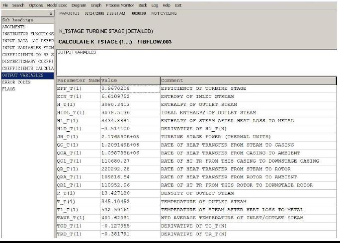
5 Mass balance in each zone gives the hold-up of solid particles. The flow rate of solid particles leaving each zone is a function of the feeder speed, mass hold-up, and the flow rate of primary air. Heat balance on the air gives the temperature of outlet air. Latent heat of evaporation of moisture and heat of grinding are considered in the heat balance. Effects of temperature and moisture content on the grindability of solids are also included. STEAM TURBINE STAGE In this model, the stage power, the outlet steam properties (entropy, enthalpy), and metal temperatures are calculated. Given the inlet steam enthalpy and pressure, the entropy is determined from thermodynamic relationships. First assuming isentropic expansion, the ideal enthalpy at the outlet is calculated from the inlet entropy and the outlet pressure. The stage efficiency is determined at various flow conditions and stored in a table. Using the ideal enthalpy and the stage efficiency, the actual enthalpy at the outlet is then calculated. The product of flow and enthalpy difference gives the power. Heat balances are performed to obtain the temperature of the rotor and the casing. GAS TURBINE This model assumes polytropic expansion in the turbine. Given the inlet temperature and the (pressure) expansion ratio, the outlet temperature is determined. Using the flue gas flow rate, inlet and outlet heat capacity, and temperatures, the power developed in the turbine is calculated. The heat capacity is determined from flue composition and temperature (from the thermodynamic properties library). Heat balances are performed to obtain the temperature of the rotor and the casing. COMBUSTION CHAMBER The combustion chamber receives fuel flow and air flow as inputs. Given the composition of the fuel and air, stoichiometric calculations are performed to determine the availability of oxygen for combustion. The amount of heat produced by combustion is then calculated from the usual series of combustion reactions. Heat balance is performed to determine the adiabatic flame temperature. Another heat balance is performed to calculate the temperature of the flue gas leaving the chamber, accounting for heat loss to any heat exchangers and surroundings. The pressure in the chamber is calculated from the mass balance. PUMP The flow rate of a centrifugal pump is determined by the correlation between the dynamic head and flow. These curves are provided by the pump vendor. A parabolic equation is used to represent these curves at various pump speeds. The flow rate then becomes a function of inlet pressure, outlet pressure, pump speed, and pump characteristic constants. COMPRESSOR The flow rate of a centrifugal compressor is determined by the correlation between the
6 polytropic head and flow. These curves are provided by the compressor vendor. A parabolic equation is used to represent these curves at various compressor speeds. The polytropic head is a function of compression (pressure) ratio, inlet temperature, molecular weight of gas, and heat capacity ratio (Cp/Cv). The power used by the compressor is a function of polytropic head and flow rate. The temperature of the outlet gas is determined from the inlet temperature and polytropic pressure ratio. VALVE This model simulates the operation of a valve. Various characteristic equations are included, such as linear flow, equal percentage flow, etc. Valve ramp function is included. The final valve opening is based on availability of power or air (fail position) and any malfunction. ELECTRICAL GENERATOR The model for the electrical generator includes the simulation of the excitation system (Automatic Voltage Regulation). This provides the field current sent to the generator. The no load saturation curve (provided by the generator vendor) is used to determine the EMF, given the field current. The difference between the grid frequency and the generator rotor speed gives the slip. The phase difference is calculated from the rotor angle and the terminal voltage angle. All these parameters are used to calculate the terminal voltage, active power, and reactive power. 5.0 PROCESS ALGORITHMS COEFFICIENT CALCULATION LIBRARY This feature of the Model Development Package reflects the most significant enhancement in Dynamic Simulation Software Technology. For each Process Algorithm, there is a corresponding Coefficient Calculation Algorithm in this Library. In most common Model Development Procedures, the simulation engineer is required to manually calculate the coefficients, such as heat transfer coefficients, valve coefficients, engineering correlation coefficients, etc. from reference plant data. In the SIMPACK package, the coefficients for the entire plant are calculated online, automatically, and instantly. The simulation engineer simply enters the reference plant data and gives a command. The system calculates the coefficients, while checking the mass and energy balances, stores the results in ASCII and/or BINARY format, and produces automatic documentation. In each of the Coefficient Calculation Algorithms, the mathematical equations which represent dynamic mass balance, energy balance, etc., are rearranged in steady-state format, and the respective coefficients are calculated from the given reference data. The thermodynamic properties of various components are utilized from the THERMODYNAMIC PROPERTIES LIBRARY. The simulation engineer also has the opportunity to check for any errors in the mass and energy balances, and correct these, even before testing the dynamics.
7 Using the Coefficient Calculation feature in this package, the simulation engineer saves significant amount of time required for calculations, error checking, testing and documentation of input data and calculated coefficients. 6.0 THERMODYNAMIC PROPERTY ALGORITHMS LIBRARY The components in this Library are water (any state), steam (any state), water & steam mixture, air (oxygen, and nitrogen), flue gas (water vapor, oxygen, nitrogen and carbon dioxide). The thermodynamic properties of each component is calculated in the respective Algorithm by polynomial expressions. The Process Algorithms extensively use the Thermodynamic Property Algorithms. Each of following properties is calculated with respect to one or more of the other properties: Temperature Enthalpy Entropy Pressure Density or Specific Volume Heat Capacity (air, flue gas, etc.) Heat of combustion 7.0 GENERAL ALGORITHMS LIBRARY A number of General Algorithms are provided, to be used in the Process Algorithms, as required. The following categories are included: Integration with respect to time First order lag Ramp Function Maximum & Minimum Limits Scaling & Unscaling Interpolation Timers Pulse Generator Logical Functions, such as Flip-flops PID Controller
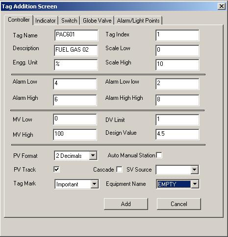
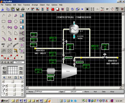
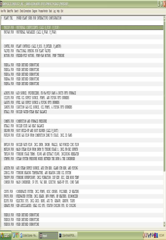
8 8.0 MODEL CONFIGURATION & CALCULATION OF COEFFICIENTS The Model Configurator is a template based and an interactive program which works in the Windows environment. The simulation engineer invokes this program to configure or build the dynamic Model of the plant. The plant to be simulated is usually divided into smaller sections to enhance the flexibility in testing and debugging. Each section is represented by a sub-model. The Model Configurator opens as an Applications Window with a Function Menu to configure the sub-model. To configure the sub-models, the simulation engineer follows procedure described below: Select the sub-model to be configured from the displayed table. Click on the ADD button on the Function Menu. A table of functional groups of Algorithms is presented. Select the appropriate group. A table of Algorithms is presented that belong in the functional group. Select the appropriate Algorithm. A template of connectivity parameters is displayed with descriptions and blank spaces to enter values. The connectivity parameters require equipment identification and input/output stream identification numbers. On-line Documentation and Help is available. Several other functions are available on the Function Menu to aid in the configuration process, for example, MODIFY (change the connectivity data) DELETE (remove selected Algorithm from the sub-model) LIST (display a list of all Algorithms used in the sub-model) REVIEW (display documentation of selected Algorithm) WRITE (save the configured file in the appropriate directory) HELP (select a subject and display contents of the Help file) EXIT (end of the configuration session) The Model Configurator has another important function available on the Function Menu, CALCULATE: Select the sub-model from the displayed table. Select the Algorithm from the sub-model for coefficient calculation. A template of inputs, coefficients, and outputs is displayed with descriptions and blank spaces to enter values. The simulation engineer enters reference data in the input columns and executes the model. The coefficients are calculated and the results are displayed immediately in the template. The simulation engineer views the coefficients and outputs from the Algorithm, determines the results to be satisfactory, and saves the file in the appropriate directory. This file will be used later for dynamic testing and documentation. This procedure is repeated for all Algorithms in all the sub-models. The Composite results give all the required coefficients and a reference initial condition of the plant.
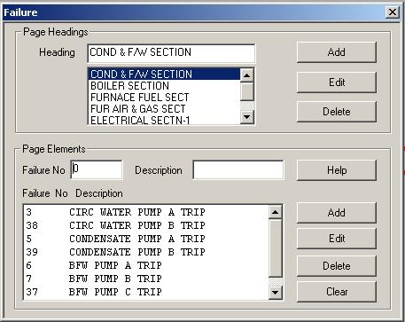
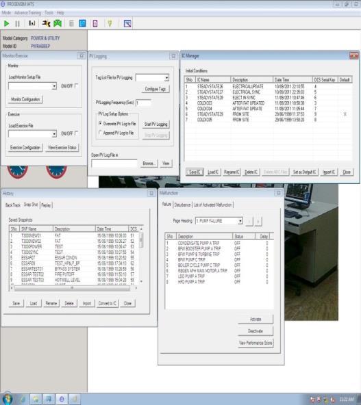
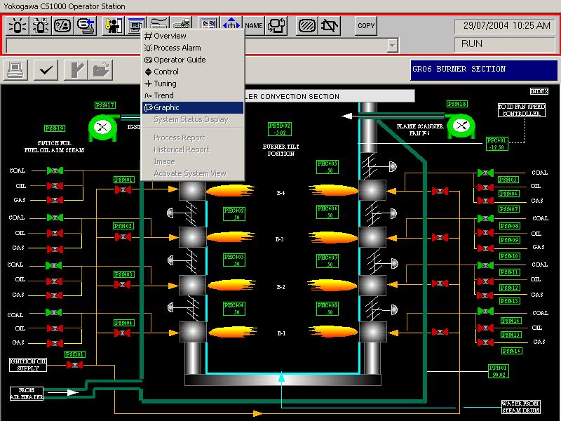
9 9.0 INTERACTIVE PROCESS MONITOR AND DEBUGGER The SIMPACK Interactive Process Monitor and Debugger is a powerful, user-friendly, dynamic monitoring and debugging program. The program provides many functions to the simulation engineer which allow the interactive monitoring and changing of process variables and coefficients, while the simulation model is running. The program is designed to run stand-alone, accessing process variables via the simulation database shareable segment. This program includes the capability to: Show, Enter, or Alter variables and coefficients on-line Turn individual integrators ON/OFF Turn all integrators ON/OFF Turn individual Algorithms ON/OFF Turn sub-models ON/OFF Create functional groups of variables to be viewed on the same screen Save/Restore functional groups of variables Create/Save/Restore display screens Run/Stop the simulation model Save/Restore the database in BINARY or ASCII Step through the simulation model one cycle at a time (very important debugging tool) Rename the commands for the convenience of the simulation engineer Change the simulation time scale (faster/slower than real time) Change the integration time step Execute commands from a file Help (on-line documentation, and helpful hints) 10.0 USER MANUAL The SIMPACK User Manual provides complete information to the simulation engineer about the organization of the software package, description of all Algorithms in the Libraries, procedures and tasks required for the dynamic simulation project, and several examples. Each of the above nine topics is a chapter in the manual.
10
11
Problems in chapter 9 CB Thermodynamics
 Problems in chapter 9 CB Thermodynamics 9-82 Air is used as the working fluid in a simple ideal Brayton cycle that has a pressure ratio of 12, a compressor inlet temperature of 300 K, and a turbine inlet
CHAPTER 2 STUDY OF 210 MW BOILER SYSTEM 2.1 DESCRIPTION OF 210 MW BOILER
 8 CHAPTER 2 STUDY OF 210 MW BOILER SYSTEM 2.1 DESCRIPTION OF 210 MW BOILER Detailed study has been carried out on a 210 MW boiler system with regard to model development, control and optimization. Figure
OUTCOME 2 TUTORIAL 2 STEADY FLOW PLANT
 UNIT 47: Engineering Plant Technology Unit code: F/601/1433 QCF level: 5 Credit value: 15 OUTCOME 2 TUTORIAL 2 STEADY FLOW PLANT 2 Be able to apply the steady flow energy equation (SFEE) to plant and equipment
Preface to the First Edition Preface to the Second Edition. Acknowledgment
 Dedication Preface to the First Edition Preface to the Second Edition Forewords Acknowledgment iii xiii xv xvii xix Chapter 1 Introduction to Pipeline Systems 1 1.1 Introduction 1 1.2 Liquid Pipelines
MECHANICAL ENGINEERING DEPARTMENT, OITM
 Sem.:4 th Subject: Energy Conversion Paper: ME-201E UNIT-1 Q1. Explain the seismometer with its working principle. (Important Question) (20) Q2. Classify the fuels and define calorific value of fuels.
Chapter 10 POWER CYCLES. Department of Mechanical Engineering
 Chapter 10 VAPOR AND COMBINED POWER CYCLES Dr Ali Jawarneh Department of Mechanical Engineering Hashemite University it 2 Objectives Analyze vapor power cycles in which h the working fluid is alternately
Thermodynamics: An Engineering Approach, 6 th Edition Yunus A. Cengel, Michael A. Boles McGraw-Hill, 2008
 Thermodynamics: An Engineering Approach, 6 th Edition Yunus A. Cengel, Michael A. Boles McGraw-Hill, 2008 Chapter 5 MASS AND ENERGY ANALYSIS OF CONTROL VOLUMES SUMMARY 1 CONSERVATION OF MASS Conservation
MARAMA Webinar August 7, Angelos Kokkinos Chief Technology Officer Babcock Power, Inc.
 MARAMA Webinar August 7, 2014 Angelos Kokkinos Chief Technology Officer Babcock Power, Inc. Rankine cycle is a thermodynamic cycle which converts heat into work. The heat is supplied externally to a closed
R13 SET - 1 '' ''' '' ' '''' Code No: RT31035
 R13 SET - 1 III B. Tech I Semester Regular/Supplementary Examinations, October/November - 2016 THERMAL ENGINEERING II (Mechanical Engineering) Time: 3 hours Max. Marks: 70 Note: 1. Question Paper consists
Chapter 10 VAPOR AND COMBINED POWER CYCLES
 Thermodynamics: An Engineering Approach, 6 th Edition Yunus A. Cengel, Michael A. Boles McGraw-Hill, 2008 Chapter 10 VAPOR AND COMBINED POWER CYCLES Copyright The McGraw-Hill Companies, Inc. Permission
Chapter 1 STEAM CYCLES
 Chapter 1 STEAM CYCLES Assoc. Prof. Dr. Mazlan Abdul Wahid Faculty of Mechanical Engineering Universiti Teknologi Malaysia www.fkm.utm.my/~mazlan 1 Chapter 1 STEAM CYCLES 1 Chapter Objectives To carry
AREN 2110: Thermodynamics Spring 2010 Homework 7: Due Friday, March 12, 6 PM
 AREN 2110: Thermodynamics Spring 2010 Homework 7: Due Friday, March 12, 6 PM 1. Answer the following by circling the BEST answer. 1) The boundary work associated with a constant volume process is always
A. the temperature of the steam at the turbine exhaust increases. B. additional moisture is removed from the steam entering the turbine.
 P77 Overall nuclear power plant thermal efficiency will decrease if... A. the temperature of the steam at the turbine exhaust increases. B. additional moisture is removed from the steam entering the turbine.
NUCLEAR TRAINING CENTRE COURSE 134 FOR ONTARIO HYDRO USE ONLY
 NUCLEAR TRAINING CENTRE COURSE 134 FOR ONTARIO HYDRO USE ONLY NUCLEAR TRAINING COURSE COURSE 134 1 - Level 3 - Equipment & System Principles 4 - TURBINE, GENERATOR & AUXILIARIES Index 134.00-0 Objectives
PAPER-I (Conventional)
") 1. a. PAPER-I (Conventional) 10 kg of pure ice at 10 ºC is separated from 6 kg of pure water at +10 O C in an adiabatic chamber using a thin adiabatic membrane. Upon rupture of the membrane, ice and water
1. a. PAPER-I (Conventional) 10 kg of pure ice at 10 ºC is separated from 6 kg of pure water at +10 O C in an adiabatic chamber using a thin adiabatic membrane. Upon rupture of the membrane, ice and water
ProSimPlus Library (Standard version + rate base option)
") ProSimPlus Library (Standard version + rate base option) Contents UNIT OPERATIONS... 5 Absorber... 5 Absorber with reboiler... 5 Rigorous two-phase distillation (L-V) with partial condenser and decanter...
ProSimPlus Library (Standard version + rate base option) Contents UNIT OPERATIONS... 5 Absorber... 5 Absorber with reboiler... 5 Rigorous two-phase distillation (L-V) with partial condenser and decanter...
ME ENGINEERING THERMODYNAMICS UNIT III QUESTION BANK SVCET
 1. A vessel of volume 0.04m 3 contains a mixture of saturated water and steam at a temperature of 250 0 C. The mass of the liquid present is 9 kg. Find the pressure, mass, specific volume, enthalpy, entropy
S.Y. Diploma : Sem. III [PG/PT/ME] Thermal Engineering
![S.Y. Diploma : Sem. III [PG/PT/ME] Thermal Engineering](/thumbs/95/122495961.jpg "S.Y. Diploma : Sem. III [PG/PT/ME] Thermal Engineering") S.Y. Diploma : Sem. III [PG/PT/ME] Thermal Engineering Time: 3 Hrs. Prelim Question Paper Solution [Marks : 70 Q.1 Attempt any FIVE of the following. [10] Q.1(a) Explain difference between Thermodynamic
S.Y. Diploma : Sem. III [PG/PT/ME] Thermal Engineering Time: 3 Hrs. Prelim Question Paper Solution [Marks : 70 Q.1 Attempt any FIVE of the following. [10] Q.1(a) Explain difference between Thermodynamic
Chapter 8. Vapor Power Systems
 Chapter 8 Vapor Power Systems Introducing Power Generation To meet our national power needs there are challenges related to Declining economically recoverable supplies of nonrenewable energy resources.
PI Heat and Thermodynamics - Course PI 25 CRITERION TEST. of each of the following a. it
 Heat and Thermodynamics - Course PI 25 CRITERION TESTS PI 25-1 - 1. Define: heat temperature (c) enthalpy 2. State the applies to meaning water: of each of the following a. it saturation temperature subcooled
Chapter 5 MASS AND ENERGY ANALYSIS OF CONTROL VOLUMES
 Thermodynamics: An Engineering Approach Seventh Edition in SI Units Yunus A. Cengel, Michael A. Boles McGraw-Hill, 2011 Chapter 5 MASS AND ENERGY ANALYSIS OF CONTROL VOLUMES Copyright The McGraw-Hill Companies,
Vapor and Combined Power Cycles
 9 CHAPTER Vapor and Combined Power Cycles 9-1 The Simple Ideal Rankine Cycle The 9-2 Rankine Cycle: Actual Vapor Power Deviation and Pump and Turbine Irreversibilities (a) Deviation of actual vapor power
Chapter 5 MASS AND ENERGY ANALYSIS OF CONTROL VOLUMES
 Thermodynamics: An Engineering Approach Seventh Edition Yunus A. Cengel, Michael A. Boles McGraw-Hill, 2011 Chapter 5 MASS AND ENERGY ANALYSIS OF CONTROL VOLUMES Copyright The McGraw-Hill Companies, Inc.
University of Strathclyde Faculty of Engineering
 University of Strathclyde Faculty of Engineering Energy Systems and the Environment: Part A Examination Monday 19 January 2004 14.00-17.00, M329 Full-time students should attempt FOUR questions, 1 from
THERMAL POWER PLANT SIMULATOR TPP 200 LABORATORY EXERCISE TUTORIAL N4: INTRODUCTION TO THE HEAT PRODUCTION SYSTEM
 EKV THERMAL POWER PLANT SIMULATOR TPP 200 LABORATORY EXERCISE TUTORIAL N4: INTRODUCTION TO THE HEAT PRODUCTION SYSTEM Master of Science Thesis Division of Heat and Power Technology 2003 Department of Energy
CHAPTER 3 MODELLING AND SIMULATION
 58 CHAPTER 3 MODELLING AND SIMULATION 3.1 NEED FOR SIMULATION Simulation is the use of modeling to represent (but not replicate ) a system or process at an appropriate level of detail, and thereby help
Faculty of Engineering 2 nd year 2016 Mechanical Engineering Dep. Final-exam (code: M 1222)
") Benha University Thermodynamics II Faculty of Engineering 2 nd year 2016 Mechanical Engineering Dep. Final-exam (code: M 1222) Time: Three Hours (attempt all questions) (assume any missing data) Question1
Benha University Thermodynamics II Faculty of Engineering 2 nd year 2016 Mechanical Engineering Dep. Final-exam (code: M 1222) Time: Three Hours (attempt all questions) (assume any missing data) Question1
water is typically used as the working fluid because of its low cost and relatively large value of enthalpy of vaporization
 Rankine Cycle Reading Problems 10-2 10-7 10-16, 10-34, 10-37, 10-44, 10-47, 10-59 Definitions working fluid is alternately vaporized and condensed as it recirculates in a closed cycle water is typically
Chapter 5 MASS AND ENERGY ANALYSIS OF CONTROL VOLUMES
 Thermodynamics: An Engineering Approach Seventh Edition in SI Units Yunus A. Cengel, Michael A. Boles McGraw-Hill, 2011 Chapter 5 MASS AND ENERGY ANALYSIS OF CONTROL VOLUMES Mehmet Kanoglu University of
Chapters 5, 6, and 7. Use T 0 = 20 C and p 0 = 100 kpa and constant specific heats unless otherwise noted. Note also that 1 bar = 100 kpa.
 Chapters 5, 6, and 7 Use T 0 = 20 C and p 0 = 100 kpa and constant specific heats unless otherwise noted. Note also that 1 bar = 100 kpa. 5-1. Steam enters a steady-flow device at 16 MPa and 560 C with
- 2 - SME Q1. (a) Briefly explain how the following methods used in a gas-turbine power plant increase the thermal efficiency:
 Briefly explain how the following methods used in a gas-turbine power plant increase the thermal efficiency:") - 2 - Q1. (a) Briefly explain how the following methods used in a gas-turbine power plant increase the thermal efficiency: i) regenerator ii) intercooling between compressors (6 marks) (b) Air enters a
- 2 - Q1. (a) Briefly explain how the following methods used in a gas-turbine power plant increase the thermal efficiency: i) regenerator ii) intercooling between compressors (6 marks) (b) Air enters a
ME 215. Mass and Energy Analysis of Control Volumes CH-6 ÇANKAYA UNIVERSITY. Mechanical Engineering Department. Open Systems-Control Volumes (CV)
") ME 215 Mass and Energy Analysis of Control Volumes CH-6 ÇANKAYA UNIVERSITY Mechanical Engineering Department Open Systems-Control Volumes (CV) A CV may have fixed size and shape or moving boundaries Open
ME 215 Mass and Energy Analysis of Control Volumes CH-6 ÇANKAYA UNIVERSITY Mechanical Engineering Department Open Systems-Control Volumes (CV) A CV may have fixed size and shape or moving boundaries Open
TOPIC: KNOWLEDGE: K1.01 [2.5/2.5]
![TOPIC: KNOWLEDGE: K1.01 [2.5/2.5]](/thumbs/96/127964750.jpg "TOPIC: KNOWLEDGE: K1.01 [2.5/2.5]") KNOWLEDGE: K1.01 [2.5/2.5] P283 The transfer of heat from the reactor fuel pellets to the fuel cladding during normal plant operation is primarily accomplished via heat transfer. A. conduction B. convection
KNOWLEDGE: K1.01 [2.5/2.5] P283 The transfer of heat from the reactor fuel pellets to the fuel cladding during normal plant operation is primarily accomplished via heat transfer. A. conduction B. convection
SUMMER 13 EXAMINATION
 Important Instructions to examiners: 1) The answers should be examined by key words and not as word-to-word as given in the model answer scheme. 2) The model answer and the answer written by candidate
CHAPTER 1 BASIC CONCEPTS
 GTU Paper Analysis CHAPTER 1 BASIC CONCEPTS Sr. No. Questions Jan 15 Jun 15 Dec 15 May 16 Jan 17 Jun 17 Nov 17 May 18 Differentiate between the followings; 1) Intensive properties and extensive properties,
KEPCO KEPRI Kim eui hwan
 2015 KEPIC PERFORMANCE TEST SEMINAR New Start! Open Soft Speed AGAIN KEPCO! 2015. 9. 22 KEPCO KEPRI Kim eui hwan 1 2 3 test Steam turbine test 2/42 3/42 Thermal analysis of Power Plant Cycle Grasp of the
SHRI RAMSWAROOP MEMORIAL COLLEGE OF ENGG. & MANAGEMENT B.Tech. [SEM IV (ME-41, 42,43 & 44)] QUIZ TEST-1 (Session: )
![SHRI RAMSWAROOP MEMORIAL COLLEGE OF ENGG. & MANAGEMENT B.Tech. [SEM IV (ME-41, 42,43 & 44)] QUIZ TEST-1 (Session: )](/thumbs/72/67555697.jpg "SHRI RAMSWAROOP MEMORIAL COLLEGE OF ENGG. & MANAGEMENT B.Tech. [SEM IV (ME-41, 42,43 & 44)] QUIZ TEST-1 (Session: )") QUIZ TEST-1 Q.1. In a stage of an impulse turbine provided with a single row wheel, the mean diameter of the blade ring is 80cm and the speed of the rotation is 3000rpm. The steam issues from the nozzle
QUIZ TEST-1 Q.1. In a stage of an impulse turbine provided with a single row wheel, the mean diameter of the blade ring is 80cm and the speed of the rotation is 3000rpm. The steam issues from the nozzle
Fluid Mechanics, Heat Transfer, Thermodynamics Design Project. Production of Styrene
 Fluid Mechanics, Heat Transfer, Thermodynamics Design Project Production of Styrene The feasibility of constructing a new, grass-roots, 100,000 tonne/y, styrene plant is being investigated. As part of
R13. II B. Tech I Semester Regular/Supplementary Examinations, Oct/Nov THERMODYNAMICS (Com. to ME, AE, AME) Time: 3 hours Max.
 Time: 3 hours Max.") SET - 1 1. a) Discuss about PMM I and PMM II b) Explain about Quasi static process. c) Show that the COP of a heat pump is greater than the COP of a refrigerator by unity. d) What is steam quality? What
SET - 1 1. a) Discuss about PMM I and PMM II b) Explain about Quasi static process. c) Show that the COP of a heat pump is greater than the COP of a refrigerator by unity. d) What is steam quality? What
Feedwater Heaters (FWH)
") Feedwater Heaters (FWH) A practical Regeneration process in steam power plants is accomplished by extracting or bleeding, steam from the turbine at various points. This steam, which could have produced
Feedwater Heaters (FWH) A practical Regeneration process in steam power plants is accomplished by extracting or bleeding, steam from the turbine at various points. This steam, which could have produced
Fundamental Investigation Of Whole-Life Power Plant Performance For Enhanced Geothermal Systems
 Purdue University Purdue e-pubs International Refrigeration and Air Conditioning Conference School of Mechanical Engineering 2016 Fundamental Investigation Of Whole-Life Power Plant Performance For Enhanced
Enhancement of CO2 Refrigeration Cycle Using an Ejector: 1D Analysis
 Purdue University Purdue e-pubs International Refrigeration and Air Conditioning Conference School of Mechanical Engineering 2006 Enhancement of CO2 Refrigeration Cycle Using an Ejector: 1D Analysis Elias
CHAPTER 5 MASS AND ENERGY ANALYSIS OF CONTROL VOLUMES
 Thermodynamics: An Engineering Approach 8th Edition in SI Units Yunus A. Ç engel, Michael A. Boles McGraw-Hill, 2015 CHAPTER 5 MASS AND ENERGY ANALYSIS OF CONTROL VOLUMES Objectives Develop the conservation
UNIVERSITY OF TORONTO FACULTY OF APPLIED SCIENCE AND ENGINEERING FINAL EXAMINATION, DECEMBER 2008 MIE 411H1 F - THERMAL ENERGY CONVERSION
 UNIVERSITY OF TORONTO FACULTY OF APPLIED SCIENCE AND ENGINEERING FINAL EXAMINATION, DECEMBER 2008 MIE 411H1 F - THERMAL ENERGY CONVERSION Exam Type: X Examiner: J.S. Wallace You may use your copy of the
Boiler Efficiency Testing. To understand the operation of a fire tube boiler To determine the operating efficiency of the boiler
 Boiler Efficiency Testing Objectives: To understand the operation of a fire tube boiler To determine the operating efficiency of the boiler Theory Most industrial processes require heating. This is usually
Chapter 10. In Chap. 9 we discussed gas power cycles for which the VAPOR AND COMBINED POWER CYCLES. Objectives
 Chapter 0 VAPOR AND COMBINED POWER CYCLES In Chap. 9 we discussed gas power cycles for which the working fluid remains a gas throughout the entire cycle. In this chapter, we consider vapor power cycles
POWER PLANT- BOILER OPERATIONS SIMULATOR
 POWER PLANT- BOILER OPERATIONS SIMULATOR The PS-5030 is a simulation software package is rigorous and detailed simulation models of POWER PLANT-Boiler Operations and processing facilities. The package
20/06/2011 Seminar on Geothermal Exploitation Santiago de Chile
 Contents Power Plants Steam Power plants Binary Power plants Geothermal Power Plants Single flash systems Binary systems 1 Equipment Well head Gathering piping system Steam separators and moisture separators
Chapter 10. In Chap. 9 we discussed gas power cycles for which the VAPOR AND COMBINED POWER CYCLES. Objectives
 Chapter 0 VAPOR AND COMBINED POWER CYCLES In Chap. 9 we discussed gas power cycles for which the working fluid remains a gas throughout the entire cycle. In this chapter, we consider vapor power cycles
Boiler and. steadily increases while the supply decreases energy
 FEATURE ARTICLE by William G. Acker ENERGY SURVEYS FOR Stewart Cohen/Stone The efficient use of energy is fast becoming a top concern for industry. As business managers become more conscientious about
Appendix B. Glossary of Steam Turbine Terms
 Operator s Guide to General Purpose Steam Turbines: An Overview of Operating Principles, Construction, Best Practices, and Troubleshooting. Robert X. Perez and David W. Lawhon. 2016 Scrivener Publishing
Power Engineering II. Technological circuits of thermal power plants
 Technological circuits of thermal power plants Lay out scheme of coal power plant climatetechwiki.com Technological circuits 2 Coal and ash circuit Air and gas circuit Feed water and steam circuit Cooling
Design Features of Combined Cycle Systems
 Design Features of Combined Cycle Systems 1.0 Introduction As we have discussed in class, one of the largest irreversibilities associated with simple gas turbine cycles is the high temperature exhaust.
Combined Cycle Power Plants. Combined Cycle Power Plant Overview (Single- and Multi-Shaft) Training Module. ALSTOM (Switzerland) Ltd )*+,
 Training Module. ALSTOM (Switzerland) Ltd )*+,") Power Plant Overview Training Module ALSTOM (Switzerland) Ltd )*+, We reserve all rights in this document and in the information contained therein. Reproduction, use or disclosure to third parties without
Power Plant Overview Training Module ALSTOM (Switzerland) Ltd )*+, We reserve all rights in this document and in the information contained therein. Reproduction, use or disclosure to third parties without
Exergy in Processes. Flows and Destruction of Exergy
 Exergy in Processes Flows and Destruction of Exergy Exergy of Different Forms of Energy Chemical Energy Heat Energy Pressurised Gas Electricity Kinetic Energy Oxidation of Methane ΔH = -890.1 kj/mol ΔS
MCG THERMODYNAMICS II. 22 April 2008 Page 1 of 7 Prof. W. Hallett
 Faculté de génie Génie mécanique Faculty of Engineering Mechanical Engineering MCG2131 - THERMODYNAMICS II 22 April 2008 Page 1 of 7 Prof. W. Hallett Closed book. Non-programmable calculators only allowed.
CHAPTER 3 HEURISTIC APPROACH TO MODELING THE BOILER FURNACE
 CHAPTER 3 HEURISTIC APPROACH TO MODELING THE BOILER FURNACE 3.1 INTRODUCTION Modeling and simulation of boiler systems has been an interesting subject of investigation for many years. Mathematical modeling
Fluid Mechanics, Heat Transfer, and Thermodynamics Fall Design Project. Production of Dimethyl Ether
 Fluid Mechanics, Heat Transfer, and Thermodynamics Fall 2001 Design Project Production of Dimethyl Ether We are investigating the feasibility of constructing a new, grass-roots, 50,000 tonne/y, (1 tonne
C. heating turbine exhaust steam above its saturation temperature. D. cooling turbine exhaust steam below its saturation temperature.
 P74 (B2277) Condensate depression is the process of... A. removing condensate from turbine exhaust steam. B. spraying condensate into turbine exhaust steam. C. heating turbine exhaust steam above its saturation
Eng Thermodynamics I: Sample Final Exam Questions 1
 Eng3901 - Thermodynamics I: Sample Final Exam Questions 1 The final exam in Eng3901 - Thermodynamics I consists of four questions: (1) 1st Law analysis of a steam power cycle, or a vapour compression refrigeration
Performance Improvement of Single-Flash Geothermal Power Plant Applying Three Cases Development Scenarios Using Thermodynamic Methods
 Proceedings World Geothermal Congress 2015 Melbourne, Australia, 19-25 April 2015 Performance Improvement of Single-Flash Geothermal Power Plant Applying Three Cases Development Scenarios Using Thermodynamic
2. The data at inlet and exit of the turbine, running under steady flow, is given below.
 3 rd week quiz 1. Identify the correct path of fluid flow in a steam power plant. a) Steam turbine-pump-boiler-condenser. b) Economizer- evaporator- superheater. c) Pump-turbine-condenser-evaporator. d)
Engineering Thermodynamics
 Unit 61: Engineering Thermodynamics Unit code: D/601/1410 QCF level: 5 Credit value: 15 Aim This unit will extend learners knowledge of heat and work transfer. It will develop learners understanding of
Chapter-2 LITERATURE REVIEW. A brief review of previous and ongoing research investigations on thermal
 Chapter-2 LITERATURE REVIEW A brief review of previous and ongoing research investigations on thermal desalination processes is presented in this chapter. The chapter begins with the introduction of the
OPTIMIZATION OF PARAMETERS FOR HEAT RECOVERY STEAM GENERATOR (HRSG) IN COMBINED CYCLE PLANTS
 IN COMBINED CYCLE PLANTS") OPTIMIZATION OF PARAMETERS FOR HEAT RECOVERY STEAM GENERATOR (HRSG) IN COMBINED CYCLE PLANTS Muammer Alus, Milan V. Petrovic University of Belgrade-Faculty of Mechanical Engineering, Laboratory of Thermal
OPTIMIZATION OF PARAMETERS FOR HEAT RECOVERY STEAM GENERATOR (HRSG) IN COMBINED CYCLE PLANTS Muammer Alus, Milan V. Petrovic University of Belgrade-Faculty of Mechanical Engineering, Laboratory of Thermal
Power Optimization Center Leveraging plant process data for advanced analytical diagnostics. June 16, 2016
 Power Optimization Center Leveraging plant process data for advanced analytical diagnostics June 16, 2016 POWER OPTIMIZATION CENTER: OVERVIEW Jamie Dugan Equipment Reliability Manager Mike Batte Fleet
HW-1: Due Tuesday 13 Jun 2017 by 2:00:00 pm EDT to Your Division s GradeScope Site
 HW-1: Due Tuesday 13 Jun 2017 by 2:00:00 pm EDT to A residential ceiling fan is shown in the photograph below. It consists of an electric motor, the fan blades, and the light. Sketch each of these three
MAHARASHTRA STATE BOARD OF TECHNICAL EDUCATION (Autonomous) (ISO/IEC Certified)
 (ISO/IEC Certified)") WINTER 16 EXAMINATION Model Answer Subject Code: 17410 Important Instructions to examiners: 1) The answers should be examined by key words and not as word-to-word as given in the model answer scheme. 2)
WINTER 16 EXAMINATION Model Answer Subject Code: 17410 Important Instructions to examiners: 1) The answers should be examined by key words and not as word-to-word as given in the model answer scheme. 2)
Overall nuclear power plant thermal efficiency will decrease if... A. the temperature of the steam at the turbine exhaust increases.
 P77 Overall nuclear power plant thermal efficiency will decrease if... A. the temperature of the steam at the turbine exhaust increases. B. additional moisture is removed from the steam entering the turbine.
Energy Systems. Program: Erasmus
 University of Ljubljana Fakulty of mechanical engineering Aškerčeva 6 SI-000 Ljubljana, Slovenia tel.: +6 400 fax: +6 556 http://www.fs.uni-lj.si e-mail: dekanat@fs.uni-lj.si Department of Energy Engineering
Department of Mechanical Engineering. MSc/PGDip/PGCert in Energy Systems and the Environment. Specialist Modules
 Department of Mechanical Engineering MSc/PGDip/PGCert in Energy Systems and the Environment Specialist Modules Wednesday 17 January 2007 2.00pm 5.00pm (3 hours) Full-time MSc/PGDip/PGCert students should
S.E. (Mechanical) (First Semester) EXAMINATION, 2012 APPLIED THERMODYNAMICS (2008 PATTERN) Time : Three Hours Maximum Marks : 100
 (First Semester) EXAMINATION, 2012 APPLIED THERMODYNAMICS (2008 PATTERN) Time : Three Hours Maximum Marks : 100") Total No. of Questions 12] [Total No. of Printed Pages 8 Seat No. [4162]-111 S.E. (Mechanical) (First Semester) EXAMINATION, 2012 APPLIED THERMODYNAMICS (2008 PATTERN) Time : Three Hours Maximum Marks
Total No. of Questions 12] [Total No. of Printed Pages 8 Seat No. [4162]-111 S.E. (Mechanical) (First Semester) EXAMINATION, 2012 APPLIED THERMODYNAMICS (2008 PATTERN) Time : Three Hours Maximum Marks
ISOBUTANE GEOTHERMAL BINARY CYCLE SENSITIVITY ANALYSIS
 131 ISOBUTANE GEOTHERMAL BINARY CYCLE SENSITIVITY ANALYSIS K. Z.Iqbal, L. W. Fish, and K. E. Starling School of Chemical Engineering and Materials Science, The University of Oklahoma, Norman, Oklahoma
Fluid Mechanics, Heat Transfer, Thermodynamics. Design Project. Production of Ammonia
 Fluid Mechanics, Heat Transfer, Thermodynamics Design Project Production of Ammonia Your assignment is to continue evaluating the details of a process to produce 50,000 tonne/y of ammonia from a syngas
Multi-Variable Optimisation Of Wet Vapour Organic Rankine Cycles With Twin-Screw Expanders
 Purdue University Purdue e-pubs International Compressor Engineering Conference School of Mechanical Engineering 2014 Multi-Variable Optimisation Of Wet Vapour Organic Rankine Cycles With Twin-Screw Expanders
Lecture No.1. Vapour Power Cycles
 Lecture No.1 1.1 INTRODUCTION Thermodynamic cycles can be primarily classified based on their utility such as for power generation, refrigeration etc. Based on this thermodynamic cycles can be categorized
Fluid Mechanics, Heat Transfer, Fluid Mechanics Design Project. Production of Ethanol
 Fluid Mechanics, Heat Transfer, Fluid Mechanics Design Project Production of Ethanol Your assignment is to continue evaluating the details of a process to produce 30,000 tonne/y of ethanol from ethylene.
STEAM TURBINE-GENERATOR & AUXILLIARY SYSTEMS Presentation by: RANA NASIR ALI General Manager, Power Plants Projects, at PITCO November 02, 2017
 STEAM TURBINE-GENERATOR & AUXILLIARY SYSTEMS Presentation by: RANA NASIR ALI General Manager, Power Plants Projects, at PITCO November 02, 2017 CO-GENERTATION POWER PLANT CONCEPT For dimensioning, design
Guidance page for practical work 15: modeling of the secondary circuit of a PWR
 Guidance page for practical work 15: modeling of the secondary circuit of a PWR 1) Objectives of the practical work The aim is to investigate the potential of Thermoptim in modeling and calculation of
Developing a Design and Simulation Tool for Coupling Thermal Desalination Plants with Nuclear Reactors by using APROS Simulator
 Developing a Design and Simulation Tool for Coupling Thermal Desalination Plants with Nuclear Reactors by using APROS Simulator Khairy Agha,, Khalid Al Fared, Ali Rashed, and Salem Ghurbal Simulation Group,
Chapter Two. The Rankine cycle. Prepared by Dr. Shatha Ammourah
 Chapter Two The Rankine cycle Prepared by Dr. Shatha Ammourah 1 The Ideal Rankine Cycle Schematic Diagram of ideal simple Rankine 2 Superheater Economizer line 3 Heat Addition Types In The Steam Generator
Modeling Techniques for Increased Accuracy
 SECTION 1 Modeling Techniques for Increased Accuracy Ed Haack Duke Energy 1-1 Modeling Techniques for Increased Accuracy By Ed Haack, Duke Power Company The PEPSE model for the Catawba Units have been
Chapter 5: Thermodynamic Processes and Cycles
 Chapter 5: Thermodynamic Processes and Cycles 5-6) This problem examines the Rankine heat engine introduced in Figure 5-5. Saturated steam at T = 250 C enters the turbine and the condenser operates at
Fluid Mechanics, Heat Transfer, Thermodynamics Design Project. Production of Ethylbenzene
 Fluid Mechanics, Heat Transfer, Thermodynamics Design Project Production of Ethylbenzene We continue to investigate the feasibility of constructing a new, grass-roots, 80,000 tonne/y, ethylbenzene facility.
R13. (12M) efficiency.
 efficiency.") SET - 1 II B. Tech I Semester Regular/Supplementary Examinations, Oct/Nov - 2016 THERMAL AND HYDRO PRIME MOVERS (Electrical and Electronics Engineering) Time: 3 hours Max. Marks: 70 Note: 1. Question Paper
SET - 1 II B. Tech I Semester Regular/Supplementary Examinations, Oct/Nov - 2016 THERMAL AND HYDRO PRIME MOVERS (Electrical and Electronics Engineering) Time: 3 hours Max. Marks: 70 Note: 1. Question Paper
Modelling and dynamic co-simulation studies of oxy-fired power plant
 Abstract Modelling and dynamic co-simulation studies of oxy-fired power plant Hannu Mikkonen 1*, Mikko Jegoroff 1, Jari lappalainen 2 and Jouni Savolainen 2 1 VTT Technical Research Centre of Finland Ltd,
Boilers & Fired Systems. Clean Coal Technology Dr. Tanveer Iqbal
 Boilers & Fired Systems Clean Coal Technology Dr. Tanveer Iqbal 1 What is a Boiler? Vessel that heats water to become hot water or steam At atmospheric pressure water volume increases 1,600 times Hot water
Reading Problems , 11.36, 11.43, 11.47, 11.52, 11.55, 11.58, 11.74
 Rankine Cycle Reading Problems 11.1 11.7 11.29, 11.36, 11.43, 11.47, 11.52, 11.55, 11.58, 11.74 Definitions working fluid is alternately vaporized and condensed as it recirculates in a closed cycle the
Fluid Mechanics, Heat Transfer, and Thermodynamics Design Project. Production of Acrylic Acid
 Fluid Mechanics, Heat Transfer, and Thermodynamics Design Project Production of Acrylic Acid We are investigating the feasibility of constructing a new, grass-roots, 50,000 metric tons/year, acrylic acid
Coal Fired Power POWER GENERATION. Rev. 2
 POWER GENERATION Coal Fired Power Coal Fired Power plants will continue to play a key role in the generation portfolio of most power companies, even while facing political pressure and competition from
Cleaner Production and Energy Efficiency in Industry. With Focus on the Electricity Supply
 Cleaner Production and Energy Efficiency in Industry With Focus on the Electricity Supply 1 Cleaner Production (CPEE) Prevent or reduce pollution and waste by implementing measures that are: Environmentally
Revue des Energies Renouvelables Spécial ICT3-MENA Bou Ismail (2015) Numerical study of a single effect ejector-absorption cooling system
 Numerical study of a single effect ejector-absorption cooling system") Revue des Energies Renouvelables Spécial ICT3-MENA Bou Ismail (2015) 71-77 Numerical study of a single effect ejector-absorption cooling system D. Sioud 1*, M. Bourouis 2 et A. Bellagi 1 1 Unité de Recherche
Revue des Energies Renouvelables Spécial ICT3-MENA Bou Ismail (2015) 71-77 Numerical study of a single effect ejector-absorption cooling system D. Sioud 1*, M. Bourouis 2 et A. Bellagi 1 1 Unité de Recherche
Chapter 13 Coal Boiler Flue Gas Scrubber
 Chapter 13 Coal Boiler Flue Gas Scrubber The Application The following case study is a limestone flue gas scrubber. Coal-fired boiler flue gas is quenched and sent to the scrubber where it mixes with wet
Eng Thermodynamics I - Examples 1
 Eng3901 - Thermodynamics I - Examples 1 1 pdv Work 1. Air is contained in a vertical frictionless piston-cylinder. The mass of the piston is 500 kg. The area of the piston is 0.005 m 2. The air initially
Enthalpy Calculations. Change in enthalpy can occur because of change in temperature, change in phase, or mixing of solutions and reactions.
 Enthalpy Calculations Change in enthalpy can occur because of change in temperature, change in phase, or mixing of solutions and reactions. Enthalpy Change as a Result of Temperature Sensible heat is the
ENERGY AND EXERGY ANALYSIS OF HEAT PUMP USING R744/R32 REFRIGERANT MIXTURE
 THERMAL SCIENCE, Year 2014, Vol. 18, No. 5, pp. 1649-1654 1649 ENERGY AND EXERGY ANALYSIS OF HEAT PUMP USING R744/R32 REFRIGERANT MIXTURE by Fang WANG, Xiao-Wei FAN, Jie CHEN, and Zhi-Wei LIAN School of
Evaluation of the Impact of Off-Design Operation on an Air-Cooled Binary Power Plant. G. L. Mines. September 22, 2002 September 25, 2002
 INEEL/CON-02-00793 PREPRINT Evaluation of the Impact of Off-Design Operation on an Air-Cooled Binary Power Plant G. L. Mines September 22, 2002 September 25, 2002 Geothermal Resources Council Annual Meeting
CONTROL VOLUME ANALYSIS USING ENERGY. By Ertanto Vetra
 CONTROL VOLUME ANALYSIS USING ENERGY 1 By Ertanto Vetra Outlines Mass Balance Energy Balance Steady State and Transient Analysis Applications 2 Conservation of mass Conservation of mass is one of the most