Influence of System Factors on Energy Consumption During Resistance Welding
|
|
|
- Shona Benson
- 6 years ago
- Views:
Transcription
1 Influence of System Factors on Energy Consumption During Resistance Welding February 21, 2013 Jerry E. Gould Technology Leader Resistance and Solid State Welding ph: Page 1

2 Specific Energy (J/mm 3 ) Relative Energy Consumption for Various Welding Methods Expectations RSW as low energy consumption Ontario Hydro study Examination of specific energies for various processes Counter-intuitive observations Focus of current discussion Low High Low High Low High Low High Low High Low High SMAW GTAW FCAW GMAW SAW ESW/ESSC RSSW Process/Power Level Page 2
 Calculations for different: Material types Sheet thicknesses Energies range from a few hundred to a few thousand Joules 10000 1000 100 Steel Al Ti 10 0 0.5 1 1.5 2 2.5 3 3.")
3 Energy (J) Specific energy demands to form a resistance spot weld Theoretical calculations of energies to form spot welds Assumptions of: 6 t nugget size Energy for heating up to T m Nugget melting (H f ) Calculations for different: Material types Sheet thicknesses Energies range from a few hundred to a few thousand Joules Steel Al Ti Sheet Metal Thickness (mm) Page 3
4 Actual Energy Requirements for Steel Spot Welds made with Different Heating Times Energy Weldability Lobe for 0.8-mm Bare Steel Energy Weldability Lobe for 0.8-mm HDG Steel Energy data taken from previous work Mild and galvanized steels show similar results Energy for 0.8-mm steel ~3.5kJ at 400-ms weld time Energy required drops to 500-J at 50-ms Page 4 Energy variations due to heat loss to the electrodes Short time energies compare to heat of fusion calculations for observed nugget sizes


5 Energy Consumption During Resistance Welding Topics to Be Covered Thermal aspects of energy efficiency System aspects to energy delivery Characteristics of differing power supply types Electrical response of the various systems Characteristics of energy demand for differing resistance welding variants Page 5
6 Thermal Electrical Response of Resistance Welds Resistance welding a balance of Heat generation Heat extraction Resistance heating sources Workpieces Surfaces Electrodes Heat extraction Electrodes Thermal conductivity Heat capacity Cooling water Environment (minor) Page 6
7 Energy Retained in the Weld (J) Heat Generation Characteristics of Resistance Spot Welds Water-Cooled Copper Alloy Electrode Weld Nugget Base Metal Base Metal mm steel 1-mm aluminum 10 5 Water-Cooled Copper Alloy Electrode Weld Time (ms) Simplified heat balance analysis of spot welds Effects of process conditions Influence of material type and geometry Assessments of process efficiency E C V Page 7 p T I 2 A K x 2 2 x t 1
8 Consumed Energy (J) Energy Efficiency Energy and Efficiency During Resistance Spot Welding mm steel mm steel 1.5-mm steel mm aluminum Weld Time (ms) Weld Time (ms) Energy demand curves match those seen experimentally Linear behavior with time Material differences related: Heat capacities Thermal diffusivities Melting points Page 8 Energy efficiency a strong function of weld time Material thickness effect related to: Latent heat of workpiece Heat extraction capability

9 System Mechanical Dynamics Stable weld forces critical to: Prevent inconsistent heat patterns Avoid unstable expulsion Accomplish proper forging of the projection Factors affecting mechanical response requirements Weld force Weld head inertia Collapse distance Collapse time Criteria for weld head inertia based on maintaining 95% of the applied force W head /F app typically less than 10% Requirements for fast followup heads Page 9 W F head app g ft 20x Relationship between projection collapse distance, projection collapse time, and the head weight-to-weld force ratio 2
10 Necessity for Providing Adequate Cooling for Resistance Welding Water Electrode End of Weld Time 20% of Weld Time Work Water Electrode Welding Temperature Water Temperature [Reference: Resistance Welding Manual, RWMA, p.1-4] Functions of electrode cooling: Thermal constraint of the weld nugget Mechanical stability of electrodes Page 10 Cooling essential for process stability Heat extraction implicit in the technology
 o K s p r Kc ts r ptan 1 (1 f ) K s p r Page 11")
11 Modeling Tools Temperature Profiles in Spot Weld Electrodes x r ptan p r xtan e e o e Kc ts r ptan m (1 f ) o K s p r Kc ts r ptan 1 (1 f ) K s p r Page 11
12 Electrode Radius (mm) Electrode Radius (mm) Heat Transfer Effects on the Accumulation of Electrode wear Fractio n P enetratio n= Number of Welds Kc/Ke CuZr rp e F r PTan e o XF ptan e F 1 r ptan e o r XF Tan 3 r 3 o y e y F XF 6FTan P CuZr n r r 2Tan XF XF ' i o i i i Fractio n P enetratio n= Number of Welds Page 12

13 Constraints in Maximizing Thermal Efficiencies for Resistance Welding Thermal efficiencies during resistance welding maximized by: Short cycle times High power densities Limited heat extraction Influence of heating time on process stability Influence of limited heat extraction on weld and system integrity Current state of the art for spot welding ~30% thermal efficiency Temper I (%Expulsion) Tempering Diagram for Material 'A' Dual Phase 140ksi Steel, 0.83mm Zero, Mid, Full Temper Locations Temper Time (cycles) 30 Rc 32 Rc 34 Rc 36 Rc 38 Rc 40 Rc 42 Rc Button Peel Interfacial Failures Page 13
14 Energy Delivery during Resistance Spot Welding Secondary circuit to deliver current to the workpiece Characteristics of secondary define machine efficiency Critical characteristics of the secondary System Resistance Workpiece resistance System inductance Power supply characteristics R WORK L R SYSTEM E POWER E POWER = Power input type R SYSTEM = Internal machine resistance R WORK = Workpiece resistance L = System inductance Page 14

15 Sources of Resistance in Welding Secondaries Two elements of resistance in welding secondaries System resistance Workpiece resistance System resistance defined by conductor characteristics: Length Cross-sections Materials Workpiece resistance defined by: Materials Geometries Surfaces Typical secondary resistance range from 10 s to 1000 s of µω Series summation of resistances Page 15

 logrithmic with P/w c a wide range")

16 Analysis of the Secondary Circuit for Resistance Welding Systems L = secondary inductance μ = magnetic permeability of air P = periphery of the conductor k = shape factor w c = conductor width Weld throat analysis taken from previous work Maxwell equations used to define relationship between geometry and inductance F(k) logrithmic with P/w c a wide range of values Estimates of inductance can be used to calculate current response Typical inductances on the order of 1 s to 10 s of µh Page 16 Relationship Between the Shape Factor k and the Function f(k)


17 Characteristics of Alternating Current Power Supplies Most traditional form of resistance welding power supplies R WORK Constant frequency (50- Hz 60-Hz) Power losses associated with both resistive and inductive loading Estimations of system impedance through resistive and reactive loading Estimates of power delivery efficiencies Page 17 L R SYSTEM E POWER

18 Power Efficiency Secondary Inductance (µh) Influence of Secondary Design on Efficiency of the AC Power Delivery Changes in inductance for different loop sizes Design assumptions: Conductor Dia ~50-mm Workpiece resistance ~100-µΩ System resistance ~50-µΩ Rapid increase in system inductance with loop perimeter Power factor increase Rapid reduction in deliverable power P Efficiency 0.05 Inductance Conductor Perimeter (m) P V I I V (a) Purely Resistive Load Resistive and Reactive Load Page 18


19 Types of DC Power Supplies for Resistance Welding DC systems Direct current in secondary Frequency converter systems DC pulses into transformer Page 19 MFDC MF power into transformer with rectification on secondary Reduced influence to system inductance


20 Characteristics of DC Resistance Welding Power Supplies LR circuit DC response Current and energy estimations from secondary circuit analysis Limited influence of system inductance Minimal power factor influence Large secondary diodes Influence of diode impedance R WORK L R SYSTEM E POWER + - Page 20
21 Current (A) System Resistance (µω) Loop Perimeter (m) Influence of Secondary Design on the Efficiency of DC Power Delivery P = 2-m P = 10-m Effect of system resistance Effect of Loop perimeter Welding Time (ms) Energy Efficiency 0 Estimated current response from a typical MFDC spot welding system and influence of perimeter loop size Inductance influences system rise time Changes in rise time affect total delivered energy Changes in rise time affect process response Page 21 Energy efficiency variations associated with changes in system resistance and secondary loop size. Order of magnitude loop sizes affect efficiencies only minorly MFDC Efficiencies dominated by diode resistances
22 Characteristics of Alternating Current Power Supplies Capacitor based energy storage Standard systems: High charge voltages Low system capacitances Transformer for energy conversion System can be modeled as an LRC circuit Analysis based on high current flow in welding secondary Current characteristics Rise times Peak values Schematic representation of the power circuit for a CD projection welding system C Is t Vc e t L t ( ) sin 1 1 N L C s s NR 2 s C L s Page 22

23 Current (ka) Some Aspects of System Design on Process Efficiency CD welding largely associated with projection welding Some typical CD system parameters Capacitances up to 70-kJ Charge voltages >3000-V Capacitances of 1000 s of µf System responses Currents in excess of 100-kA Rise times <10-ms Influence of secondary configuration Increasing throat sizes affect rise times and peak currents Dominance of rise times on projection weld quality Increases in energy demand based on rise times Page Time (ms) P = 0.5-m P = 2-m P = 5-m
24 Characteristics of New Generation Resistance Welding Processes Summary of system factors affecting efficiency Efficiency compared to other processes Thermal effects Inductance losses Resistance losses Balance between system utility and energy efficiency Examples from new generation processes Resistance seam cladding Flash-butt wedge repair Translationally assisted upset welding Supercapacitor power supplies Electro-spark deposition Indirect resistance heating processes Page 24


25 Resistance Seam Cladding for Linepipe CRA pipe 316SS or High Ni alloys CRA is becoming critical Gas applications with CO 2 and Cl ions Fluid applications with H 2 S Steel pipe ~10-mm wall X 350-mm diameter Inconel 625 liner rolled from sheet stock ~2-mm thick Page 25


26 Application and Advantages of Resistance Welding for Pipe Cladding Clad tube inserted into steel pipe Weld wheels pass current through the sheet stack to be bonded Weld made between CRA and substrate Expanded area by progressive overlapped seams Localized energy application Thermal control Surface protection Retention of base metal properties Page 26
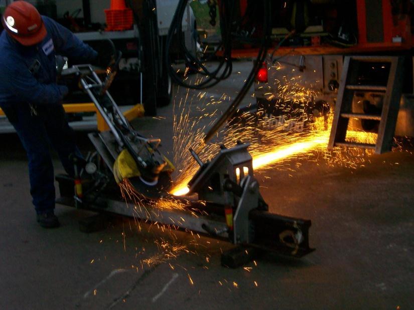
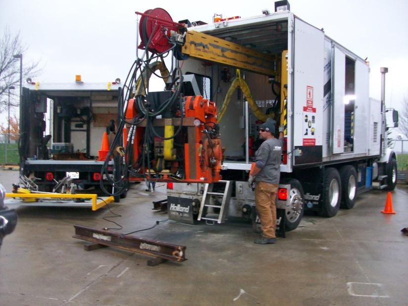
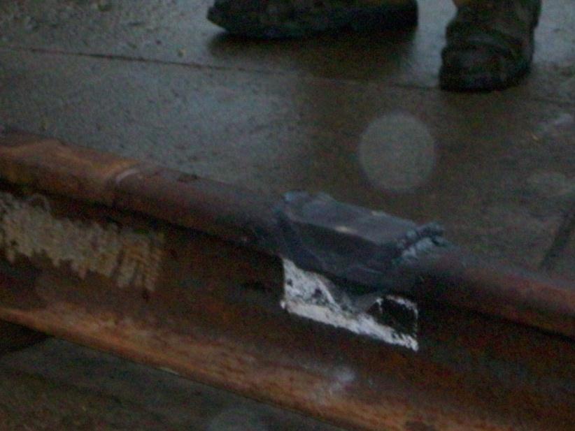
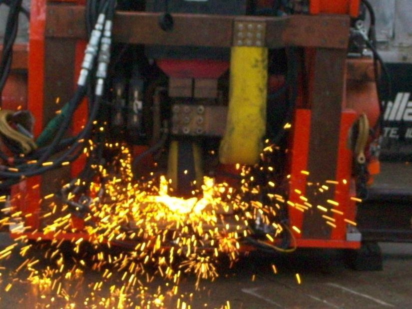
27 Flash-Butt Wedge Repair of Rails Page 27

28 Thermal and Energy Management of the Flash-Butt Wedge Repair process In-process pre-heating Cooling rate monitoring using IR Thermal Process optimization to: Minimize any residual bond line decarburization Reduce any far HAZ softening Over-harden wedge prior to welding process allow in-process heating to temper back wedge Portable power supplies Transportability Thermal management key Page 28


29 Translationally Assisted Upset Welding (TAUW) New Generation Solid State Welding Technology based on resistance butt welding Translational action to improve bond line strains Independent forging and scrubbing cylinders Page 29 Independent action of Current pulse Translational action Upset action Independent control of surface strains and heat content


30 Translationally Assisted Upset Welding - Characteristics As Welded Specimen Showing Minimal Flash Curl Bond Line Macrograph Showing Flash Curl and Bond Line Profile Details of the Bond Line Showing Re-Solutionized Microstructure Page 30

31 Supercapacitors Applied as Resistance Welding Power Sources Conventional dry capacitors Layered electrodes Dielectric separator Capacitance through static charge attraction Capacitance limited by breakdown voltage of separator Limited capacitance values Construction of supercapacitors Double wound capacitor Incorporates carbon electrodes Electrodes wound with a permeable separator Charge stored through ionic separation Separate charge surfaces at each electrode Micro-scale separators High surface to separation ratios High achievable capacitances Page 31 Supercapacitor Functionality, taken from Green and Jehoulet, 2002
 High specific capacitance")

32 Advantages of Supercapacitor based for Spot Welding Systems Supercapacitors as a candidate alternate power supply CD power supplies established for RPW Supercapacitors as an alternative to conventional capacitors Low operating voltage (<5V) High specific capacitance (kf) High specific energy (kj) Rapid charge and discharge cycles High output currents Long life (10 6 cycles) Potential for welding without transformers Weight reduction Cost reduction potential Page 32 Maxwell K2 Series Supercapacitors Nippon Chemi Con DLCAP Series Supercapacitors


33 Electrical Analysis of a Supercapacitor Driven Spot Welding Secondary C = System capacitance R cap = Internal capacitor resistance R work = Workpiece resistance V c = Charging voltage N caps = Number of capacitors in parallel Predicted Response from a Supercapacitor Based Welding Gun. Analysis is based on 2.7-V, 3000F capacitors with a 0.29-mΩ internal resistance, four caps in parallel, and a gun loop perimeter of 2-m. Page 33
34 Influence of Electrical Circuit Factors on Deliverable Currents The Influence of Gun Throat Size on the Current Response from a Supercapacitor Based Spot Welding System. Calculations are done for four parallel 2.7V, 3000-F Maxwell supercapacitors. The Influence of Charge Voltage on the Current Response from a Supercapacitor Based Spot Welding System. Calculations are done for four parallel 2.7V, 3000-F Maxwell supercapacitors and a 2-m perimeter gun secondary. Page 34
35 Influence of the Numbers of Parallel Caps on the Electrical Efficiency of the Process The Influence of the Number of Parallel Caps on the Fraction Energy Delivered to the Workpiece. Calculations are done using 2.7V, 3000-F Maxwell supercapacitors and a 2-m perimeter gun secondary, calculating energy at the workpiece compared to that of the total system. Page 35
36 Current (A) Electro-Spark Deposition A Localized Resistance Repair Process Local surface buildup for cosmetic repair Deposits without cracking or distortion Process sensitive to a range of factors: Power supply Torch Mechanical Setup Spark emission during manual ESA deposition Three primary components Power supply ESA torch Motion control Page Time (micro-seconds)
37 Temp (deg C) Cooling rate (deg C/sec) Thermal Analysis of Various Localized Deposition Processes GTAW PAW PTA LBW ESD 1.E+06 1.E+05 1.E+04 GTAW PAW PTA LBW ESD E E E Distance (mm) 1.E Temp (deg C) Arc and Laser Processes: V Rx Q 2 T e To 2 KR Arc and Laser Processes: dt dt V 2 2 K T T o Q ESD: 1 x Cp Tm To T Tm Tm To erf xsp H m ESD: dt dt 2 Cp x H 2 sp m T T 2 m o Page 37


38 High-Speed Video Studies for Electro-Spark Alloying Video Imaging done at 62,500 frames per second CMOS camera technology full frames in a single 16- s exposure Power-sparking sequencing Details of the sparking event Current waveform effects Current waveform and synchronized video images for electro-spark alloying using a Sheldon power supply Current waveform and synchronized video images for electro-spark alloying using an ASAP power supply Page 38

39 V2(V), I2(A) Deposit Thickness (um) Characteristics of Electro- Spark Deposits Splat thicknesses on the order of microns Deposition rates on the order of 100 s of microns/sec Splat quenching Buildups of unweldable alloys Cooling rates observed in access of 10 6 o C/s Adaptable to dissimilar metals combinations Location (in) Coating microstructure and associated variation in thickness taken using quantitative microscopy V2(volts) I2(A) Time (microseconds) Voltage and current waveforms taken at the torch for the ASAP power supply Page 39

 600 500 400 Shear Zinc Micros 300 200 100 0 1.")
 Zinc re-flow at the center of a braze joint at best practice conditions (Courtesy CellTech Metals) Zinc re-flow at the edge of a braze joint at best practice")
40 Tensile Shear Force (N) Use of Thermal Constructs for Preliminary Cost Scaling of New Technologies Application: High speed indirect resistance brazing of internally reinforced panels Thin gauge construction Automotive customer Development of roll brazing technology Resistively heated rolls Flood cooling to control overall thermal cycle Integration of low cost materials Mild and AHSS steels Galvanized coating as the braze alloy Preliminary trials on resistance brazing using the galvanized coating Reflow with single point resistance heating Joint strengths ~50% that of full spot welds Schematic Representation of a Roll Brazing System for Low Cost Honeycomb Panel Construction (Courtesy CellTech Metals) Shear Zinc Micros Peak Weld Current (KA) Zinc re-flow at the center of a braze joint at best practice conditions (Courtesy CellTech Metals) Zinc re-flow at the edge of a braze joint at best practice conditions (Courtesy CellTech Metals) Strengths for Joints made at Increasing Currents Showing the Transitino from Brazing to Welding (Courtesy CellTech Metals)
41 Temperature, C Line Speed (m/min) Preliminary Assessments of the High Speed Manufacturing System for Automotive Panel Thermal analyses for predicting strip heating and cooling Closed form solutions Geometric and material property effects Estimates of heating and cooling dynamics Temperature-time relationships at each interface Estimates of processing requirements Total thermal cycles on the order of 10s of milliseconds Speeds in the range of m/min Influence of panel design Estimates of currents and voltages Demonstration trials underway n w ( 1) (2n1) x w exp 2 n0 2n 1 4( 12) v Equation Defining Conductive Heating Associated with the Hot Roll Technology (Courtesy CellTech Metals) 0 ( h 0 )exp v 2 v 2 K H ( Equation Defining Cooling Associated with the Hot Roll Technology (Courtesy CellTech Metals) x R) mm core 1.0-mm core 1.5-mm core Location in X Direction, m Heating and Cooling Profile for a 1.5-mm Thick Panel During Resistance Roll Brazing (Courtesy CellTech Metals) Page Strip Thickness (mm) Relationships Between Panel Geometry Factors and Line Speed for Resistance Roll Brazing (Courtesy CellTech Metals)
42 Influence of System Factors on Energy Consumption During RW Summary Energy consumption compared to other welding technologies Thermal effects Electrical effects Influence of power systems Tradeoffs between efficiency and performance Examples from emerging RW technologies Resistance seam cladding Flash-butt wedge repair Translationally assisted upset welding Supercapacitor power supplies Electro-spark deposition Indirect resistance heating Page 42
43 Questions? Jerry E. Gould Technology Leader Resistance and Solid State Welding EWI ph:

44 Page 44
Advances in Solid-State Joining at EWI
 Advances in Solid-State Joining at EWI Jerry E. Gould Technology Leader Resistance and Solid-State Joining ph: 614-688-5121 e-mail: jgould@ewi.org Brian Thompson Applications Engineer Friction Stir Welding
Novel Technologies for Similar and Dissimilar Titanium Joints
 Novel Technologies for Similar and Dissimilar Titanium Joints October 8, 2012 Michael Eff Project Engineer 614.688.5212 meff@ewi.org EWI. dedicated to Materials Joining and related process development
RWMA Q&A BY JERRY GOULD
 RWMA Q&A BY JERRY GOULD Q: Reducing energy consumption is a constant theme in our production facility. Our industrial engineering staff look at the instantaneous power demands of our resistance welding
Development of a Solid State Joining Process Incorporating Bi-Axial Deformation: Translationally Assisted Upset Welding (TAUW)
") Development of a Solid State Joining Process Incorporating Bi-Axial Deformation: Translationally Assisted Upset Welding (TAUW) April 29, 2014 Jerry E. Gould Technology Leader Resistance and Solid State
Development of a Solid State Joining Process Incorporating Bi-Axial Deformation: Translationally Assisted Upset Welding (TAUW) April 29, 2014 Jerry E. Gould Technology Leader Resistance and Solid State
Welding Processes. Consumable Electrode. Non-Consumable Electrode. High Energy Beam. Fusion Welding Processes. SMAW Shielded Metal Arc Welding
 Fusion Consumable Electrode SMAW Shielded Metal Arc Welding GMAW Gas Metal Arc Welding SAW Submerged Arc Welding Non-Consumable Electrode GTAW Gas Tungsten Arc Welding PAW Plasma Arc Welding High Energy
Improving Electrode Life for RSW of Coated Advanced High Strength Steel
 Improving Electrode Life for RSW of Coated Advanced High Strength Steel D. Huh, Z. Jiao, Y. Zhou Centre for Advanced Materials Joining, University of Waterloo, 200 University Ave. W, Waterloo, ON N2L 3G1,
Application of Forced Freeze during Flash-Butt Welding for Coil Joining of Advanced High Strength Steels (AHSS)
") Application of Forced Freeze during Flash-Butt Welding for Coil Joining of Advanced High Strength Steels (AHSS) Michael Prokop * and Jerry E. Gould ** * Taylor-Winfield Technologies ** EWI Abstract Recent
Application of Forced Freeze during Flash-Butt Welding for Coil Joining of Advanced High Strength Steels (AHSS) Michael Prokop * and Jerry E. Gould ** * Taylor-Winfield Technologies ** EWI Abstract Recent
Joining as an Enabling Technology for Mainstream Vehicle Lightweighting
 Joining as an Enabling Technology for Mainstream Vehicle Lightweighting March 17, 2015 Jerry E. Gould LIFT: Technology Pillar Leader, Joining and Assembly EWI: Technology Leader, Resistance and Solid State
Welding Lecture August 2016, Tuesday am. Welding Processes- Resistance welding
 Welding Lecture - 9 16 August 2016, Tuesday 11.00-11.50 am Welding Processes- Resistance welding 1 1 Resistance welding (RW) Generate heat through the resistance to the flow of electric current in parts
Chapter 32 Resistance Welding and Solid State Welding. Materials Processing. Classification of Processes. MET Manufacturing Processes
 MET 33800 Manufacturing Processes Chapter 32 Resistance Welding and Solid State Welding Before you begin: Turn on the sound on your computer. There is audio to accompany this presentation. Materials Processing
Resistance Welding. Resistance Welding (RW)
") Resistance Welding (RW) Resistance Welding 1 Resistance Welding is a welding process, in which work pieces are welded due to a combination of a pressure applied to them and a localized heat generated by
Resistance Welding (RW) Resistance Welding 1 Resistance Welding is a welding process, in which work pieces are welded due to a combination of a pressure applied to them and a localized heat generated by
Durability Testing of Ceramic Coatings for Indirect Resistance Heat Treating in Vehicle Lightweighting Applications
 Durability Testing of Ceramic Coatings for Indirect Resistance Heat Treating in Vehicle Lightweighting Applications Warren Peterson and Jerry E. Gould EWI Abstract The need for vehicle lightweighting has
Introduction to Welding Technology
 Introduction to Welding Technology Welding is a fabrication process used to join materials, usually metals or thermoplastics, together. During welding, the pieces to be joined (the workpieces) are melted
Casting Forming and Welding Lab (ME39007) Experiment No. 3: Resistance Welding
 Experiment No. 3: Resistance Welding") Casting Forming and Welding Lab (ME39007) Experiment No. 3: Resistance Welding Introduction Resistance spot welding (RSW) is a process in which faying surfaces are joined by the heat generated by resistance
Casting Forming and Welding Lab (ME39007) Experiment No. 3: Resistance Welding Introduction Resistance spot welding (RSW) is a process in which faying surfaces are joined by the heat generated by resistance
Welding Solutions for Advanced High-Strength Steels Menachem Kimchi 1
 Welding Solutions for Advanced High-Strength Steels Menachem Kimchi 1 A. Peer 1, Y. Lu 1, W. Zhang 1, C. Ji 2, Y. Park 2, T. Abke 3, S. Malcom 3 1 The Ohio State University, 2 Dong-Eui University, 3 Honda
COMPARISON OF WELDING/BONDING METHODS
 TYPE OF WELDING/BONDING Adhesive Bonding Diffusion Welding Electron Beam Welding Explosive Welding SUMMARY ADVANTAGES DISADVANTAGES Bond is established through use of an intermediate adhesive layer applied
TECHNIQUES FOR IMPROVING THE WELDABILITY OF TRIP STEEL USING RESISTANCE SPOT WELDING. G Shi and S A Westgate TWI Ltd, Cambridge, United Kingdom
 TECHNIQUES FOR IMPROVING THE WELDABILITY OF TRIP STEEL USING RESISTANCE SPOT WELDING G Shi and S A Westgate TWI Ltd, Cambridge, United Kingdom ABSTRACT High strength steels (UTS >6N/mm 2 ) are increasingly
Chapter 32: Resistance and Solid-State Welding Processes. DeGarmo s Materials and Processes in Manufacturing
 Chapter 32: Resistance and Solid-State Welding Processes DeGarmo s Materials and Processes in Manufacturing 32.1 Introduction 32.2 Theory of Resistance Welding Basic Resistive Welding FIGURE 32-1 The basic
Small-Scale Resistance Welding for Medical and Industrial Applications
 Small-Scale Resistance Welding for Medical and Industrial Applications Girish P. Kelkar, Ph.D. (author of The Weld Nugget ) http://www.welding-consultant.com/ Excellence In Material Joining Difference
Materials & Processes in Manufacturing
 2003 Bill Young Materials & Processes in Manufacturing ME 151 Chapter 37 Arc Processes Chapter 38 Resistance Welding Chapter 39 Brazing and Soldering 1 Introduction Arc welding processes produce fusion
The Simulation Software for Innovative Welding and Joining. Ensure before welding
 The Simulation Software for Innovative Welding and Joining Ensure before welding Strategic partner for success With more than 25 years of continuous research and development and nearly 20 years of devoted
Analysis of Spot Weld Growth on Mild and Stainless Steel
 SUPPLEMENT TO THE WELDING JOURNAL, AUGUST 2011 Sponsored by the American Welding Society and the Welding Research Council Analysis of Spot Weld Growth on Mild and Stainless Steel Nugget growth by varying
Resistance Spot Welding, Resistance Projection Welding. and Resistance Seam Welding
 8. Resistance Spot Welding, Resistance Projection Welding and Resistance Seam Welding 8. Resistance Spot-, Resistance Projection- and Resistance Seam Welding 05 Figure 8. shows an extract from the classification
WELDING TECHNOLOGY AND WELDING INSPECTION
 WELDING TECHNOLOGY AND WELDING INSPECTION PRESENTED BY: GOPAL KUMAR CHOUDHARY SVL ENGINEERING SERVICES CHENNAI CONTENTS: DEFINATION TYPES OF WELDING ELECTRODE GEOMETRY EQUIPMENT QUALITY PROCESS SAFETY
To ensure success, this work was carried out in three phases. At first, the electrical-thermal process associated
 Page 1 of 15 Joining Technologies: Finite Element Modelling Of Electrode Wear Mechanisms (April 10, 1995) Introduction 1.0 Introduction Resistance spot welding is the principal joining method in auto body
Expulsion Reduction in Resistance Spot Welding by Controlling of welding Current Waveform
 Available online at www.sciencedirect.com Procedia Engineering 10 (2011) 2775 2781 International conference on the mechanical behavior of materials Expulsion Reduction in Resistance Spot Welding by Controlling
Resistance Spot Welding of Coated High Strength Dual Phase Steels
 Resistance Spot Welding of Coated High Strength Dual Phase Steels Murali D. Tumuluru United States Steel Corporation Research and Technology Center Monroeville, Pa Topics Introduction Dual Phase Steels
Weldability of AHSS. Dr. Sree Harsha Lalam, CWEng. Mittal Steel Company. w w w. a u t o s t e e l. o r g
 Weldability of AHSS Dr. Sree Harsha Lalam, CWEng. Mittal Steel Company Overview AHS Steels & Weld Joint Spot welding Spot Welding Window Effect of Coating AC vs. Mid-Frequency DC Weldmetal Hardness Mechanical
Lecture 16 Gas Tungsten Arc welding III & Plasma Arc Welding Keyword: 16.1 Selection of pulse parameters
 Lecture 16 Gas Tungsten Arc welding III & Plasma Arc Welding This chapter presents the influence of process parameters of pulse TIG welding process on the development of sound weld joint. Further, the
Solid-State Welding Processes
 Solid-State Welding Processes Text Reference: Manufacturing Engineering and Technology, Kalpakjian & Schmid, 6/e, 2010 Chapter 31 Solid-State State Welding Processes Joining takes place without fusion
INFLUENCES OF SECONDARY PULSE ON RESISTANCE SPOT WELDING OF HOT FORMING STEELS. Jeff Hou
 2014 International Symposium on Advances in Resistance Welding, Atlanta INFLUENCES OF SECONDARY PULSE ON RESISTANCE SPOT WELDING OF HOT FORMING STEELS Jeff Hou D.Saha, S. Nayak, N.Zhou, A.Gerlich (UofWaterloo)
Effect of Welding Current on the Mechanical Response of Resistance Spot Welds of Unequal Thickness Steel Sheets in Tensile-Shear Loading Condition
 Effect of Welding Current on the Mechanical Response of Resistance Spot Welds of Unequal Thickness Steel Sheets in Tensile-Shear Loading Condition M. Pouranvari Materials and Metallurgical Engineering
Chapter Outline. Joining Processes. Welding Processes. Oxyacetylene Welding. Fusion Welding Processes. Page 1. Welded Joints
 Joining Processes Chapter Outline R. Jerz 1 4/16/2006 R. Jerz 2 4/16/2006 Welding Processes Welded Joints Gas, electricity, or other heat source? Is electrode consumed? Is a filler material used? Is flux
Joining Processes R. Jerz
 Joining Processes R. Jerz 1 4/16/2006 Chapter Outline R. Jerz 2 4/16/2006 Welding Processes Gas, electricity, or other heat source? Is electrode consumed? Is a filler material used? Is flux used? Anything
Content. perform. Brief profile. Product information for high-strength thermomechanically hot-rolled strip and cut-to-length plate
 Steel perform Product information for high-strength thermomechanically hot-rolled strip and cut-to-length plate Issue: January 22, 2019, version 0 / WB 660 Brief profile Outstanding surface quality Bending
REGRESSION MODELING AND PROCESS ANALYSIS OF RESISTANCE SPOT WELDED JOINTS
 5 th International & 26 th All India Manufacturing Technology, Design and Research Conference (AIMTDR 214) December 12 th 14 th, 214, IIT Guwahati, Assam, India Abstract REGRESSION MODELING AND PROCESS
Solid-State Welding Processes. Solid State Bonding 12/2/2009. Cold Welding
 Solid-State Welding Processes Solid-State Welding Processes Text Reference: Manufacturing Engineering and Technology, Kalpakjian & Schmid, 6/e, 2010 Chapter 31 Joining takes place without fusion at the
Resistance Welding Principle
 Resistance Welding Principle In resistance welding heat is generated by the electrical resistance of the work pieces and the interface between them. Pressure is supplied externally and is varied throughout
American Journal of Engineering Research (AJER) 2013
 2013") American Journal of Engineering Research (AJER) e-issn : 2320-0847 p-issn : 2320-0936 Volume-02, Issue-06, pp-79-93 www.ajer.org Research Paper Open Access Use Of Dynamic Resistance And Dynamic Energy
American Journal of Engineering Research (AJER) e-issn : 2320-0847 p-issn : 2320-0936 Volume-02, Issue-06, pp-79-93 www.ajer.org Research Paper Open Access Use Of Dynamic Resistance And Dynamic Energy
Copyright 1999 Society of Manufacturing Engineers FUNDAMENTAL MANUFACTURING PROCESSES Welding NARRATION (VO):
:") Copyright 1999 Society of Manufacturing Engineers --- 1 --- FUNDAMENTAL MANUFACTURING PROCESSES Welding SCENE 1. CG: Fusion Welding Processes white text centered on black SCENE 2. tape 528, 14:18:33-14:18:52
Copyright 1999 Society of Manufacturing Engineers --- 1 --- FUNDAMENTAL MANUFACTURING PROCESSES Welding SCENE 1. CG: Fusion Welding Processes white text centered on black SCENE 2. tape 528, 14:18:33-14:18:52
Roll Bonding or Roll Welding
 1 2 3 4 Roll Bonding or Roll Welding The pressure required for welding is applied through a pair of rolls Can be performed hot (Hot Roll Bonding) Surface preparation is important for interfacial bonding
Finite Element Simulation of the Process of Aluminum. Alloy Resistance Spot Welding
 Finite Element Simulation of the Process of Aluminum Alloy Resistance Spot Welding Li Baoqing, Shan Ping, Lian Jinrui, Hu Shengsun, Cheng Fangjie Tianjin University, Tianjin, P.R.C Abstract In this paper,
Content. CP-W and CP-K. Areas of application. Product information for complex-phase steels
 Steel CP-W and CP-K Product information for complex-phase steels Issue: January 2017, version 2 Overview of steel grades 50 Hot-rolled flat products Cold-rolled/hot-dip coated flat products Recommended
Fundamentals. of Small Parts Resistance Welding
 Fundamentals of Small Parts Resistance Welding GENERAL PRINCIPLES Resistance welding is a thermo-electric process in which heat is generated at the interface of the parts to be joined by passing an electrical
Resistance Spot Welding of Aluminum Alloy to Steel with Transition Material From Process to Performance Part I: Experimental Study
 Resistance Spot Welding of Aluminum Alloy to Steel with Transition Material From Process to Performance Part I: Experimental Study Weld strength, failure mode, and fatigue life were compared with self-piercing
WELDING Topic and Contents Hours Marks
 Topic and Contents Hours Marks 3.1 Introduction 04 Marks Classification and selection of welding process. Working principle of Gas welding and types of flames. 3.2 Arc welding process 08 Marks Metal arc,
Manufacturing Process II. Welding Processes-1
 Manufacturing Process II Welding Processes-1 1. Introduction: The term joining is generally used for welding, brazing, soldering, and adhesive bonding, which form a permanent joint between the parts a
RESISTANCE WELDING MANUAL
 FTZSTSTA RWMA RESISTANCE WELDING MANUAL Revised Fourth Edition RWMA CONTENTS PREFACE ACKNOWLEDGEMENTS Section 1 PROCESSES Fundamentals Of Resistance Welding ;M INTRODUCTION 1-1 RESISTANCE WELDING PROCESSES
Single Pulse Resistance Welder Instruction Pamphlet CD125SP High Accuracy CD Welder
 EN G IN EERI N G Single Pulse Resistance Welder Instruction Pamphlet CD125SP High Accuracy CD Welder Fundamentals of Capacitive Discharge Resistance Welding deliver repeatable welds even during line voltage
Mechanism of Building-Up Deposited Layer during Electro-Spark Deposition
 Journal of Surface Engineered Materials and Advanced Technology, 2012, 2, 258-263 http://dx.doi.org/10.4236/jsemat.2012.24039 Published Online October 2012 (http://www.scirp.org/journal/jsemat) Mechanism
pdfmachine trial version
 EFFECT OF WELDING TECHNIQUES (GTAW & SMAW) ON THE MICROSTRUCTURE & MECHANICAL PROPERTIES OF MILD STEEL SA 516 Gr. 70 By Dr. Muhammad Taqi Zahid Butt, S. Ahmed, S. Rasool, U. Ali and S. U. Rehman* ABSTRACT
Dissimilar Metals DISSIMILAR METALS. Weld Tech News VOL 1. NO. 14
 Dissimilar Metals Weld Tech News VOL 1. NO. 14 WELD TECH NEWS is a newsletter for welders working primarily in maintenance and repair. Each issue contains useful information on materials (cast irons, steels,
The Effect of Arc Voltage and Welding Current on Mechanical and Microstructure Properties of 5083-Aluminium Alloy Joints used in Marine Applications
 EP11 The Effect of Arc Voltage and Welding Current on Mechanical and Microstructure Properties of 5083-Aluminium Alloy Joints used in Marine Applications C.W. Mohd Noor 1, Khalid Samo 2, Nurazilla 3, M.
3 TIG welding. 3.1 A description of the method. 3.2 Equipment
 3 TIG welding 3.1 A description of the method TIG welding (also called Gas Tungsten Arc Welding, GTAW) involves striking an arc between a non-consumable tungsten electrode and the workpiece. The weld pool
Introduction. Online course on Analysis and Modelling of Welding. G. Phanikumar Dept. of MME, IIT Madras
 Introduction Online course on Analysis and Modelling of Welding G. Phanikumar Dept. of MME, IIT Madras Classification of Manufacturing Processes Manufacturing Processes Ingot Casting Shape Casting Power
Keywords - Aluminium alloy, hardness, Nugget diameter, RSW, Tensile-shear load.
 Effect Of Process Parameters On The Strength Of Aluminium Alloy A5052 Sheets Joint Welded By Resistance Spot Welding With Cover Plates Chetan R. Patel*, Prof. Dhaval A. Patel** *(M.E. MECHANICAL (CAD/CAM)
Chapter 31. Solid-State Welding Processes
 Chapter 31 Solid-State Welding Processes Roll Bonding Figure 31.1 Schematic illustration of the roll bonding or cladding process. Ultrasonic Welding Figure 31.2 (a) Components of an ultrasonic welding
Cladding with High Power Diode Lasers
 White Paper Cladding with High Power Diode Lasers Cladding is a well established process used in a variety of industries for improving the surface and near surface properties (e.g. wear, corrosion or heat
MACROSTRUCTURE, MICROSTRUCTURE AND MICROHARDNESS ANALYSIS
 109 Chapter 5 MACROSTRUCTURE, MICROSTRUCTURE AND MICROHARDNESS ANALYSIS 5.1 INTRODUCTION The microstructural studies of friction welding helps in understanding microstructural changes occurred during friction
BMT Welding Guide for Stratusteel used in transportation and other heavy equipment industries.
 1017 BMT Welding Guide for Stratusteel used in transportation and other heavy equipment industries. In this guide you will find suggestions for using Stratusteel tubing in transportation and heavy equipment.
Welding and post weld heat treatment of 2.25%Cr-1%Mo steel
 University of Wollongong Thesis Collections University of Wollongong Thesis Collection University of Wollongong Year 2005 Welding and post weld heat treatment of 2.25%Cr-1%Mo steel Benjamin King University
SURFACE TREATMENT OF SONOTRODE MATERIAL AW 7075
 SURFACE TREATMENT OF SONOTRODE MATERIAL AW 7075 EMMER Štefan 1, BAKSA Peter 2, KOVÁČIK Jaroslav 34 Keywords: Electro spark deposition, substrate AW 7075, metal-ceramic functional layers, micro hardness,
International Journal of Advance Engineering and Research Development
 Scientific Journal of Impact Factor (SJIF): 5.71 International Journal of Advance Engineering and Research Development Volume 5, Issue 03, March -2018 e-issn (O): 2348-4470 p-issn (P): 2348-6406 Study
Comparison of Resistance Spot Welding and Refill Friction Stir Welding of Al 7075 Sheets. Jeff Hou
 Comparison of Resistance Spot Welding and Refill Friction Stir Welding of Al 7075 Sheets Jeff Hou Z.Shen, Y. Chen, N. Zhou, M. Worswick, A. Gerlich, K. Chan, N. Scotchmer 1 Friction Stir Welding (FSW)
Development of Next Generation Resistance Spot Welding Technologies Contributing to Auto Body Weight Reduction
 Development of Next Generation Resistance Spot Technologies Contributing to Auto Body Weight Reduction JFE TECHNCAL REPORT No. 18 (Mar. 213) MATSUSHTA Muneo *1 TANGUCH Koichi *2 O Kenji *3 Abstract: New
A Comparison of AC to Inverter DC Resistance Spot Welding and the Effects On Dual-Phase 600
 A Comparison of AC to Inverter DC Resistance Spot Welding and the Effects On Dual-Phase 600 ABSTRACT Dual-phase 600 is a mixture of ferrite matrix and martensitic islands distributed at grain boundaries
Taylor & Francis Taylor & Francis Croup Boca Raton London New York
 RESISTANCE WELDING Fundamentals and Applications Hongyan Zhang Jacek Senkara Taylor & Francis Taylor & Francis Croup Boca Raton London New York A CRC title, part of the Taylor & Francis imprint, a member
C Mn Si P S Mo Cr
 ANALYSIS OF WELDABILITY OF DUAL-PHASE STEEL SHEETS USED IN CAR BODY PRODUCTION LUBOS KASCAK, EMIL SPISAK, RENE KUBIK Technical University of Kosice, Faculty of Mechanical Engineering, Institute of Technology
Establishing Relationship between ASAW Parameters and Welding Voltage during Surfacing
 International Journal of Advanced Mechanical Engineering. ISSN 2250-3234 Volume 4, Number 6 (2014), pp. 601-609 Research India Publications http://www.ripublication.com Establishing Relationship between
Experimental Study of Tensile Test in Resistance Spot Welding Process
 1228 Experimental Study of Tensile Test in Resistance Spot Welding Process Abstract Resistance spot welding (RSW) is a widely used joining process for fabricating sheet metal assemblies in automobile industry.in
VALLIAMMAI ENGINEERING COLLEGE SRM Nagar, Kattankulathur
 VALLIAMMAI ENGINEERING COLLEGE SRM Nagar, Kattankulathur 603 203 DEPARTMENT OF MECHANICAL ENGINEERING QUESTION BANK VII SEMESTER ME 6008-WELDING TECHNOLOGY Regulation 2013 Academic Year 2017 18 Prepared
EFFECT OF UPSET CONDITION ON WELD STRENGTH, INTERFACE TEMPERATURE AND MATERIAL CONSUMPTION
 162 Chapter 7 EFFECT OF UPSET CONDITION ON WELD STRENGTH, INTERFACE TEMPERATURE AND MATERIAL CONSUMPTION 7.1 INTRODUCTION In friction welding, the optimum selection of weld parameters such as rpm, friction
Working principle Equipments Process parameters MRR Electrode / Tool Power circuits Tool wear Dielectric Flushing Advantages Limitations Applications
 Unit 3 - EDM Working principle Equipments Process parameters MRR Electrode / Tool Power circuits Tool wear Dielectric Flushing Advantages Limitations Applications Wire cut EDM Recent trends in EDM Synopsis
Induction Heating. Jean Callebaut, Laborelec. 1 Introduction Physical principles Induction Installations... 5
 Induction Heating Jean Callebaut, Laborelec 1 Introduction... 2 2 Physical principles... 2 2.1 Electromagnetic induction... 2 2.2 The Joule-effect... 3 2.3 Penetration depth... 3 3 Induction Installations...
Modelling the resistance spot welding of galvanized steel sheets using Fuzzy logic controller
 Modelling the resistance spot welding of galvanized steel sheets using Fuzzy logic controller L. Boriwal Research scholar, Mechanical Engineering Department, MANIT, Bhopal, India R. M. Sarviya Professor,
CLASSIFIATION OF WELDING PROCESSES
 Exp03: Welding Welding Welding is an art of joining metals by heating and then pressing together. Welding is a method of joining metals in which heat and/or pressure are applied to the area of contact
VARIOUS EFFECTS OF WELDING PARAMETERS ON TIG WELDING OF 2024-T3 CLAD ALUMINUM ALLOY PLATE
 VARIOUS EFFECTS OF WELDING PARAMETERS ON TIG WELDING OF 2024-T3 CLAD ALUMINUM ALLOY PLATE M. RAJKIRAN M.Tech, Production Technology, Sree Vaanmayi Istitute of Engineering, E-mail:rajkiran.dme@gmail.com
Variants of MIG/MAG Flux Cored Arc Welding (FCAW)
") Variants of MIG/MAG Flux Cored Arc Welding (FCAW) Professor Pedro Vilaça * * Contacts Address: P.O. Box 14200, FI-00076 Aalto, Finland Visiting address: Puumiehenkuja 3, Espoo pedro.vilaca@aalto.fi ; Skype:
Variants of MIG/MAG Flux Cored Arc Welding (FCAW) Professor Pedro Vilaça * * Contacts Address: P.O. Box 14200, FI-00076 Aalto, Finland Visiting address: Puumiehenkuja 3, Espoo pedro.vilaca@aalto.fi ; Skype:
Cladding and Additive Layer Manufacturing with a laser supported arc process
 Cladding and Additive Layer Manufacturing with a laser supported arc process A. Barroi, J. Hermsdorf, R. Kling Laser Zentrum Hannover e.v., Hannover, 30419, Germany Abstract This paper describes the potential
Guidelines for the Manufacture of Advanced High-Strength Steel Vehicle Applications. Dr. Chris Lahaije, Sascha Sikora Aachen,
 Guidelines for the Manufacture of Advanced High-Strength Steel Vehicle Applications Dr. Chris Lahaije, Sascha Sikora Aachen, 2014-09-24 09 24 WorldAutoSteel A t Automotive ti Group G off the th World W
Laser Beam Welding (LBW) of Aluminum Alloys
 of Aluminum Alloys") PE 225 Material Technology -2 Course Mini Project Laser Beam Welding (LBW) of Aluminum Alloys Under Supervision of Dr.Ing Islam El-Galy Contents LBW Principle Advantages of Laser Welding Limitation of
PE 225 Material Technology -2 Course Mini Project Laser Beam Welding (LBW) of Aluminum Alloys Under Supervision of Dr.Ing Islam El-Galy Contents LBW Principle Advantages of Laser Welding Limitation of
Girth welding technique on the oil and gas pipeline project of China
 Girth welding technique on the oil and gas pipeline project of China Yongli Sui ( National Engineering Laboratory for Pipeline Safety, China Petroleum Pipeline Research Institute, Langfang 065000, China)
CAPACITOR DISCHARGE (CD) WELD STUDS & STUD WELDING EQUIPMENT
 WELD STUDS & STUD WELDING EQUIPMENT") CAPACITOR DISCHARGE (CD) WELD STUDS & STUD WELDING EQUIPMENT THE WELDING PROCESS THE CAPACITOR DISCHARGE (CD) STUDWELDING PROCESS CD Studwelding is generally used to weld smaller diameter studs to thin
CAPACITOR DISCHARGE (CD) WELD STUDS & STUD WELDING EQUIPMENT THE WELDING PROCESS THE CAPACITOR DISCHARGE (CD) STUDWELDING PROCESS CD Studwelding is generally used to weld smaller diameter studs to thin
LASER GUIDED AND STABILIZED GAS METAL ARC WELDING PROCESSES (LGS-GMA)
") LASER GUIDED AND STABILIZED GAS METAL ARC WELDING PROCESSES (LGS-GMA) Jörg Hermsdorf Laser Zentrum Hannover, Germany OUTLINE Motivation Innovation Technology Project Concept Welding and Cladding Results
LASER GUIDED AND STABILIZED GAS METAL ARC WELDING PROCESSES (LGS-GMA) Jörg Hermsdorf Laser Zentrum Hannover, Germany OUTLINE Motivation Innovation Technology Project Concept Welding and Cladding Results
HOTVAR Hot work tool steel
 T OOL STEEL FACTS HOTVAR Hot work tool steel Wherever tools are made Wherever tools are used General HOTVAR is a high performance molybdenumvanadium alloyed hot-work tool steel which is characterized by:
An Experimental Investigation on Spot Weld Growth on Dissimilar Joints of 304L Austenitic Stainless Steel and Medium Carbon Steel (Part 1)
") International Journal of Advances in Applied Sciences (IJAAS) Vol. 2, No. 1, March 2013, pp. 25~32 ISSN: 2252-8814 25 An Experimental Investigation on Spot Weld Growth on Dissimilar Joints of 304L Austenitic
International Journal of Advances in Applied Sciences (IJAAS) Vol. 2, No. 1, March 2013, pp. 25~32 ISSN: 2252-8814 25 An Experimental Investigation on Spot Weld Growth on Dissimilar Joints of 304L Austenitic
Theoretical Analysis of Welding Characteristics during Resistance Mash Seam Welding of Sheet Steels
 WELDING RESERCH SUPPLEMENT TO THE WELDING JOURNL, OCTOBER 3 Sponsored by the merican Welding Society and the Welding Research Council Theoretical nalysis of Welding Characteristics during Resistance Mash
AUTOMOTIVE EXHAUST SYSTEM MATERIALS COMPARATOR
 AUTOMOTIVE EXHAUST SYSTEM MATERIALS COMPARATOR AK Steel manufactures stainless steels for exhaust system components to meet lightweighting and durability requirements. Combined with industry experience
TIG WELDING OPPORTUNITIES OF BIMETALLIC ENDLESS SAW BLADES
 TIG WELDING OPPORTUNITIES OF BIMETALLIC ENDLESS SAW BLADES Ion MITELEA a, Dumitru-Daniel OCHIAN a, Mircea BURCA a, Ion-Dragos UTU a a POLITEHNICA UNIVERSITY OF TIMISOARA, Pta Victoriei,no. 1, Timisoara,Romania,
Residual Stresses and Distortion in Weldments
 Residual Stresses and Distortion in Weldments By: Aziz Shafiei Residual Stresses 1 Causes of Residual Stresses Residual stresses in metal structures occur for many reasons during various manufacturing
Low Impedance Ta Capacitors to Serve the Needs of the Electronics Industry
 Low Impedance Ta Capacitors to Serve the Needs of the Electronics Industry Randy Hahn, and Jonathan Paulsen KEMET Electronics Corp PO Box 5928 Greenville, SC 29606 Tel: +1 864-963-6300 Fax: +1 864-228-4333
Fundamentals of Metal Forming
 Fundamentals of Metal Forming Chapter 15 15.1 Introduction Deformation processes have been designed to exploit the plasticity of engineering materials Plasticity is the ability of a material to flow as
Dissimilar Metal Joining of Aluminum and Copper Plates Using Magnetic Pulse Welding and Their Joint Strength
 Proceedings of the 4 th World Congress on Mechanical, Chemical, and Material Engineering (MCM'18) Madrid, Spain August 16 18, 2018 Paper No. MMME 118 DOI: 10.11159/mmme18.118 Dissimilar Metal Joining of
ATI 601 ATI 601. Technical Data Sheet. Nickel-base Alloy INTRODUCTION PRODUCT FORMS SPECIFICATIONS & CERTIFICATES (UNS N06601)
") Nickel-base Alloy (UNS N06601) INTRODUCTION alloy (UNS Designation N06601) is an austenitic nickel-chromium-iron alloy designed for both heat and corrosion resistance. As compared to ATI 600 alloy (UNS
Nickel-base Alloy (UNS N06601) INTRODUCTION alloy (UNS Designation N06601) is an austenitic nickel-chromium-iron alloy designed for both heat and corrosion resistance. As compared to ATI 600 alloy (UNS
Productivity Enhancements for GMAW of Titanium Carrie Davis and Michael E. Wells Naval Surface Warfare Center, Carderock Division
 Productivity Enhancements for GMAW of Titanium Carrie Davis and Michael E. Wells Naval Surface Warfare Center, Carderock Division While titanium has been used extensively in seawater cooling systems on
ME E5 - Welding Metallurgy
 ME 328.3 E5 - Welding Metallurgy Purpose: To become more familiar with the welding process and its effects on the material To look at the changes in microstructure and the hardness in the Heat Affected
Optimization of Spot Welding Processes in Low Carbon Hot Rolled Sheets
 19 th World Conference on Non-Destructive Testing 016 Optimization of Spot Welding Processes in Low Carbon Hot Rolled Sheets Asif BUTT 1, Imran SALEEM 1 Experts, Center of Science and Technology, Islamabad,
Weldability Improvement Using Coated Electrodes for RSW of HDG Steel
 2006-01-0092 Weldability Improvement Using s for RSW of HDG Steel K. R. Chan, N. Scotchmer Huys Industries Limited, 175 Toryork Drive Unit #35, Weston Ontario, M9L 1X9, Canada Copyright 2005 SAE International
Widening the Welding Lobe of Advanced High Strength Steels in the Resistance Spot Welding Process
 Strength Steels in the Resistance Spot Welding Process Nigel Scotchmer Huys Industries Limited nscotchmer@huysindustries.com Abstract The intention of this project was to examine the resistance spot welding