This document is downloaded from the Digital Open Access Repository of VTT. VTT P.O. box 1000 FI VTT Finland
|
|
|
- Adam Powers
- 5 years ago
- Views:
Transcription
1 This document is downloaded from the Digital Open Access Repository of VTT Title Finite element analysis of coating adhesion failure in pre-existing crack field Author(s) Holmberg, Kenneth; Laukkanen, Anssi; Ronkainen, Helena; Wallin, Kim Citation Tribology - Materials, Surfaces and Interfaces. Maney Publishing. Vol. 7 (2013) No: 1, Pages Date 2013 URL Rights Post-print version of the article. This article may be downloaded for personal use only. VTT P.O. box 1000 FI VTT Finland By using VTT Digital Open Access Repository you are bound by the following Terms & Conditions. I have read and I understand the following statement: This document is protected by copyright and other intellectual property rights, and duplication or sale of all or part of any of this document is not permitted, except duplication for research use or educational purposes in electronic or print form. You must obtain permission for any other use. Electronic or print copies may not be offered for sale.
2 FINITE ELEMENT ANALYSIS OF COATING ADHESION FAILURE IN A PRE-EXISTING CRACK FIELD Kenneth Holmberg, Anssi Laukkanen, Helena Ronkainen, Kim Wallin VTT Technical Research Centre of Finland, Espoo, Finland Abstract The influence of a pre-existing crack field on coating adhesion failure in a steel surface coated with a 2 micrometre thick titanium nitride (TiN) coating was investigated by finite element method (FEM) modelling and simulation. The stress and strain fields were determined in contact conditions with a spherical diamond tip sliding over the coated surface at a loading of 8 N. One crack in or at the coating increased the maximum tensile stresses with 6 times from 82 MPa to 540 MPa when the crack was vertical through the coating or L-shaped and with 9 times when the crack was horizontal at the coating/substrate interface. A simulated multicrack pattern relaxed the tensile stresses compared to single cracks. The results indicate that a cracked coated surface needs to have about 5-9 times higher adhesive and cohesive bonds to resist the same loading without crack growth compared to a crack free surface. For optimal coated surface design the strength of the adhesive bonds between the coating and the substrate in the vertical direction need to be 50% higher than the cohesive bonds within the coating and the substrate in the horizontal direction. The first crack is prone to start at the top of the coating and grows vertically down to coating/substrate interface and there it stops due to the bigger cohesion within the steel material. After this there are two effects influencing that the crack will grow in the lateral direction. One is that steel cohesion is normally bigger than coating/interface adhesion and the second is that there are higher tensile stresses in horizontal cracks than in vertical cracks. Several vertical cracks can stop the horizontal crack growth due to stress relaxation. Keywords Coating, fracture, scratch test, finite-element method, crack
3 1. Introduction There has been an increased interest in surface engineering during the last few decades. This is much due to the rapid development in the coating deposition techniques. Today it is possible to coat a surface by various techniques with almost any material. A thin layer on the surface can drastically change the friction and wear properties of the surface. A layer of a few micrometre titanium nitride can increase the lifetime of cutting tools with two orders of magnitude and a similarly thin hard diamond-like carbon layer can reduce the coefficient of friction between two sliding metal surfaces to be fifty times lower, down to values as low as This development has recently been reviewed by Holmberg and Matthews [1]. However, in certain conditions there are still problems with the reliability of coated components and there may occur cracks in the coatings resulting in unwanted wear. For this reason it is important to better understand the stresses and strains generated in loaded thin hard coatings, how they result in cracks on and close to the surface and how the cracks grow to form wear debris and generate wear. A crack perpendicular to the surface is often the start of the wear process and cracks that break the adhesive bonds in the interface between the coating and the substrate result easily in delamination of the coating. The strength of the adhesive bonds between the coating and the substrate are crucial for the functionality of a coated surface. When they break, some part of the coating will be detached and the substrate material is exposed to the counter surface in the tribological contact. This is frequently called adhesive failure, coating delamination, spalling or flaking. The adhesive failure of a coated surface is basically that the moving counterface results in a pulling force at the surface, tensional stresses higher than what the material can resist and a crack is formed often in the interface between the coating and the substrate. The crack grows and merges with vertical through-coating cracks and a coating material flake is liberated and removed. The adhesion strength between the coating and the substrate is governed by various routes for crack propagation depending on the elasticity, plasticity and ductility of the coating and the substrate and the coating thickness, and finally, typically results in spalling or buckling failure [2-4]. In practical systems is it not always clear if a failure at the coating/substrate interface is a truly adhesive failure or a cohesive failure in the coating or in the substrate along and very close to the interface. So in reality cohesive failures at the subinterface between the bulk material and the real interface to the coating are often referred to as adhesive failures [5]. Even if the theoretical definition of adhesion is clear, the assessment of adhesion is very difficult. This is reflected by the fact that there have been reported more than 350 different tests used to characterise adhesion [6-7]. Adhesion between the coating and the substrate is one important parameter but it cannot alone explain the interfacial properties. Other parameters such as geometry, applied and residual stresses and interfacial flaws are equally important. The well established field of fracture mechanics permits these aspects to be considered. One of the most important features of fracture mechanics is that it can provide means for characterising interfacial properties which does not depend on the method of testing [8-9]. Fracture near the surface often starts from imperfections in the material that form the nucleus for fracture initiation and propagation. Common imperfections are broken bonds on the interfaces, and inclusions, voids and dislocations in the layer. These imperfections have a disturbing effect on the stress field and the strains generated in the material.
4 Analytical solutions for coated surfaces with a flaw or a crack have been developed by a number of authors starting from Erdogan and Gupta [10-11] and reviewed by Hills et al. [12]. Many of the solutions are limited in use, because of the small number of cracks analysed, usually only one, and assumptions on the location of displacement zones along the crack faces. An attempt to solve the problem of a spall more typical to those observed experimentally has been presented by Breton and Dubourg [13-14]. Using a half analytical and half numerical model based on the dislocation theory they simultaneously analysed the combination of an interfacial crack that propagates at the interface and a surface breaking crack that propagates normally to the interface. The energy release rate was determined at the crack tips. With the model they could show that the crack interaction favours propagation and that the surface breaking crack propagates down to the interface and the interfacial crack propagates at the interface in a direction opposite to that of the load displacement. A theoretical model for multiple fatigue cracks situated close to a loading zone has been developed by Dubourg and Villechaise [15] and Dubourg et al. [16]. They considered straight arbitrarily oriented cracks and tested the method for up to five cracks without any indication of a limitation in crack number. For the analysis they identified five interaction mechanisms which depend on the distance between cracks, their relative position with respect to the loading zone, the interfacial crack coefficient of friction, and loading mode conditions: i.e. the step effect, the plug effect, the tilt effect, the stretch effect and the stretch-tilt effect. The mechanisms of crack initiation and crack growth in surfaces covered by thin hard coatings and used in tribological contacts are not well understood. The problem is especially challenging for two reasons. The surface is a compound of a substrate and one or several layers having different material properties, and the dimensions of the layers, typically 0.5 to 5 m, is four to five orders of magnitude smaller than the size range of the well-established linear elastic fracture mechanics concepts. Actually the dimension of the coating overlaps the size range, m, where material scientists normally define crack nucleation and initiation to take place [17]. There are some special features in the cracking of a surface covered by a thin coating. As a crack is initiated in a thin coating it normally goes all the way down to the coating/substrate interface. It may be only one single crack but often a whole system of cracks is generated [18]. When reaching the interface the crack may change direction and propagate along the coating/substrate interface or it may penetrate deeper down into the substrate. The crack growth in the lateral direction is important since it influences the conditions for coating delamination. Analytical and numerical solutions of fully and partially cracked thin coatings in a stress field in tension and unstressed have been presented by Beuth [19], Men ik [20] and Oliveira and Bower [21]. Still the use of these solutions in practical applications is not easy and straightforward due to the mathematical complexity. Finite element modelling (FEM) was used by Rabinovich and Sarin [22] to show the mechanisms of fracture in brittle materials under scratch test sliding indentation loading. The study includes frictional contact interaction, crack propagation and debonding of laminated brittle three-dimensional finite bodies. They showed that the dominating mechanism of the interfacial debonding is different for coated and homogeneous surfaces. In a FEM study of the interface cracking between a hard coating and a softer substrate in indentation Souza et al. [23] found that the interfacial cracks: (i) did not interact with the bending stresses responsible for the circular cracks observed close to the contact edge of indentations of coated systems
5 with soft substrates; (ii) reduced the constrains imposed by the substrate on the coating, which may be responsible for the propagation of the coating cracks during the unloading portion of the indentation; and (iii) resulted in an overall and localised reduction in the coating stresses in most portions of the model, which is important in areas close to the indentation axis, where a reduction in the amount of circular and radial cracks would be expected. Surface cracking of a multilayered surface due to repeated sliding of a rigid asperity was analysed by linear elastic fracture mechanics and FEM by Gong and Komvopoulos [24-25]. They studied the propagation of a partial perpendicular crack in the first coating layer and came up with several very interesting conclusions. The significantly higher values, by an order of magnitude, of the tensile stress intensity factor, K I, than those of the shear intensity factor, K II, indicate that surface cracking in a multilayered surface due to sliding is controlled by the tensile fracture mode. Longer surface cracks produce significantly higher K I values while higher friction increases both K I and K II significantly due to the strong effect of the surface shear traction on the crack-tip stresses. The increase of friction at the crack interface promotes stress relaxation but the effect on K I is negligible. The initial crack growth was found to occur at an angle of ~ 10º from the original crack plane, independent of the initial crack length. After the first one to three crack growth increments, the crack growth paths are almost parallel to each other, exhibiting a common deviation from the original crack by ~ 57º and this was reported to be in fair agreement with experimental observations. Laukkanen et al. [26] carried out a fracture mechanics evaluation of thin coated surfaces by boundary element analysis based on the stress and strain FEM analysis carried out by Holmberg et al. [27-28]. They analysed the fracture conditions in the contact of a rigid diamond sphere sliding with increased loading on a flat steel surface coated with a 2 m thick TiN coating. In addition to calculating the first principal stresses on the top of the surface and at the coating/substrate interface they calculated the true stresses in tension and in shear. They found that the highest tensile stress levels are at the surface in the sliding direction and the direction perpendicular to sliding. This explains why the first cracks observed in these conditions are typically angular cracks at the groove edge behind the slider. It clearly indicates that the surface cracking starts from the top of the coating and advances down to the interface and into the substrate. They showed that the shear stress level is lower than the tensile stresses and that the highest shear stresses are generated on top of the coating in the surface plane. Laukkanen et al. [26] further studied the influence of different crack parameters on crack growth by calculating the stress intensity factor, K, along the crack front. The tension mode I dominates the crack growth in lateral directions even if the shear mode II seems to be important for crack growth in the vertical direction. The influence from mode III is negligible in the analyses. From a crack parameter analysis they concluded that cracks vertical to the sliding direction are more prone to grow compared with cracks 20º and 45º from the vertical direction; cracks with a larger crack spacing in the regular crack field (30 m) are more prone to grow compared to smaller spacing (5 and 10 m) or single cracks; the centre crack in a crack field is more prone to grow compared to edge crack or other cracks in the field; transverse cracks in the middle of the groove are more prone to grow compared to both transverse and angular side cracks at the groove edge; and tensile load biaxiality has only a marginal influence on crack growth. In ceramic coatings the thickness and the grain size are important parameters for crack propagation. In indentation tests of 1 to 10 m thick Al 2 O 3 coatings on cemented carbide substrates Yuan and Hayashi [29] found that the critical load for generation of radial cracks decreased with increasing coating thickness and that the grain size of the coatings decreased with the thickness. A coarser grained microstructure generally displays a lower cohesive strength as compared with a fine grained
6 microstructure. Thus the fracture strength of the coating increases with decreasing grain size and decreasing thickness. For amorphous diamond-like carbon (DLC) coatings in the thickness range of 0.7 to 2 m it has been shown that the hardness and apparent fracture toughness of the coating/substrate combination, measured by Vickers indentation, depend on the thickness of the coating [30]. The hardness and the apparent fracture toughness of the coating, both of which influence the wear, increased with increasing coating thickness. The hardness and the thickness influenced the initiation of cracks, whereas the residual stress in the film influenced the propagation of cracks. In a study of very thin DLC coatings in the thickness range of 3.5 to 20 nm Sundarajan and Bhushan [31] conclude that the formation of cracks depends on the hardness and fracture toughness of the coating. They suggest that the observed non-uniform failure depends on variations in the coating properties at different locations in the material volume. Surface cracks are developed in weaker regions with lower fracture toughness. As cracks propagate they are forced to expand within the weak region, as the neighbouring strong regions inhibit extensive lateral crack growth. Because of this, cracks propagate down to the interface, where, aided by the interfacial stresses, they get diverted along the interface just enough to cause local delamination of the coating. Simultaneously the weakened regions experience excessive ploughing. Thus weaker regions fail while stronger regions remain wear-resistant. The propagation of cracks along the coating/substrate interface is suppressed due to the strong adhesion of the coating; otherwise would coating delamination take place. The objective of our recent research work has been to develop a method for optimising the mechanical properties of a coated surface to be used in tribological contacts with respect to surface fracture [26-28;32-35]. In our studies we have used a fracture mechanics approach and studied the contact condition of a sphere sliding over a surface coated with a thin hard coating. A three dimensional finite-element method (3D FEM) model has been developed for calculating the first principal stress, true stress, true shear and strain distributions, and parameters influencing the crack propagation in the contact of the spherical tip moving with increased load on a coated steel surface. The used 3D FEM model was in our previous studies compared with empirical observations and the correlation was good and encouraging. The purpose of this paper is to demonstrate with a 2D FEM model and stress and strain computer simulations the effect of single and multiple perpendicular cracks going straight through the coating and lateral cracks in the interface between the coating and the substrate both separately and combined in the pre-existing crack field. 2. Surface parameters The modelled contact condition is a ball sliding over a flat coated surface, as shown in figure 2.1. The materials are homogenous and the surfaces perfectly smooth. The two dimensional simulation figures shown in this paper are in the vertical symmetry plane along the direction of sliding. The parameters used in the simulations are the following: - the substrate is high speed steel (HSS) with hardness H = 7.5 GPa; Young s modulus E = 200 GPa; Poisson s ratio = 0.29; strain hardening coefficient = 20; and yield strength = 4100 MPa, - the coating is titanium nitride (TiN) with a thickness of h = 2 m; hardness H = 25 GPa; Young s modulus E = 300 GPa; and Poisson s ratio = 0.22, - the adhesion between the coating and the substrate outside the cracks is 100%, - the sliding tip is diamond and thus modelled as rigid with a radius of R = 200 m,
7 - the sliding condition corresponds to a scratch test situation with 8 N (4.5 N/mm) normal load and - the coefficient of adhesive friction between the tip and the coated surface is = Surface crack model The finite element analyses were carried out using the Warp3D [36] and Abaqus [37] general purpose finite element software. The contact problem is treated as a finite deformation and finite sliding analysis, where a linear-elastic tip slides above the linear-elastic coating and elastic-plastic substrate layers with boundary conditions corresponding to those specified in Chapter 2 for a typical scratch test. The basis for constructing the finite element mesh is such that using non-adaptive means cracking within the coating as well as at the coating-substrate interface can be modeled incrementally at a certain point of sliding, as presented in Figure 3.1. In order to achieve this, the mesh topology is designed such that allowance is made for through coating cracking during the scratch test followed by a dense region where crack propagation also at the interface, thus representing the adhesive failure process, is included. Mesh detail with details of various cracks in presented in Figure 3.2. In order to study the system s behavior during different cracking processes, several different crack growth variations are studied. These are the: i) non-cracking, ii) through coating cracking, iii) adhesive interface cracking, iv) through coating and interface cracking, and v) through coating cracking crack field and interface cracking cases. By generating the different analysis variants the resulting differing fields of stress and strain can be assessed. The mesh construct between the different cases is essentially similar in terms of density and near crack-tip seeding. The crack initiation and propagation process takes place in a linear-elastic material and during a minute change in the external boundary conditions of the system. The crack propagation process is specified to occur following a pre-defined path at an instance of loading identified on the basis of previous experimental and numerical work once the contacting tip has slid over the failing region, i.e. the failure initiates once the coating has resurfaced from under the contact [26-28;38]. The actual critical occurrence is specified to correspond to mean fracture toughness values determined in [26] for through coating cracks which were observed experimentally and the fracture toughness estimated on the basis of numerical means. Thus, the following crack propagation takes place via a node release approach, where once certain free surface has been created, following iterations are carried out in order for the FEM model to reach equilibrium, after which subsequent crack propagation can occur. The process is carried out repeatedly - typically for several tens of steps - until the desired crack geometry has been reached. The crack field density in the analyses where the interface crack growth is preceded by through coating cracking is as well specified on the basis of [26]. The FEM model is a 3D model with dimensions 5000 µm 250 µm 250 µm (length in sliding direction width depth), and half model symmetry is imposed. The dimensions are selected such that undesired interaction between the system boundary conditions and the area undergoing contact finite strain plasticity are avoided. Element sizing of bilinear isoparametric 3D brick elements ranges from 10 nm upwards. Kinematic incremental plasticity formulation is applied, and a Coulomb friction model with a constant coefficient of friction. Contact is enforced using a penalty function approach. Figures are 2D symmetry plane images of simulations carried out with the 3D model.
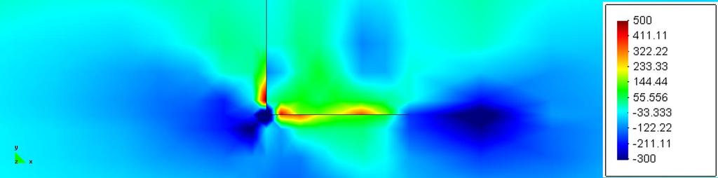
8 4. Stress and strain simulation results The stresses and strains in the coated surfaces below the sliding tip as the tip slides from left to right for the five cases with and without pre-existing cracks are shown in figures The position of the sliding tip is in all figures above the blue compressive stress area at the surface on the right hand side of the crack field. 4.1 Surface without cracks The stresses and strain in the coated loaded surface were first simulated for a surface with no preexisting cracks, as shown in figure 4.1. In figure 4.1a are the first principal stresses illustrated with a maximum compression of 1013 MPa at the surface and maximum tensile stresses of 82 MPa at the coating/substrate interface below the sliding tip. The position of the tip is above the blue compressive zone and the extension of the contact zone is about 3 m in diameter. Figure 4.1b shows that the maximum strain reaches a value of 0.2 % at the substrate/coating interface and figure 4.3c shows the shear pattern and the maximum shear stresses of values up to 304 MPa. The pure tensile stresses in the vertical direction are shown in figure 4.1d. 4.2 Surface with one vertical crack The stresses and strain were in this case simulated in a similar coated loaded surface but now with one vertical pre-existing crack going all the way through the 2 m thick coating, as shown in figure 4.2. In figure 4.2a are the first principal stresses illustrated with a maximum compression concentration of 1061 MPa just under the sliding tip and a maximum tensile stress concentration of 541 MPa on the trailing side at the crack edge. The maximum compressive stress at the tip edge is 1851 MPa. Figure 4.2b shows the large maximum strain pattern with values above 0.2 % on the right hand side of the crack and figure 4.2c shows the shear pattern and the maximum shear stresses of values up to 588 MPa just at the crack edge. The pure tensile stresses in the vertical direction are shown in figure 4.2d. 4.3 Surface with one horisontal crack The stresses and strain were in this case simulated in a similar coated loaded surface but now with one horizontal pre-existing 1 m long crack in the substrate/coating interface, as shown in figure 4.3. In figure 4.3a are the first principal stresses illustrated with a maximum compression concentration of 970 MPa under the sliding tip and small compressive stress concentrations just at both crack edges, the one on the trailing side being higher 1096 MPa. A maximum tensile stress concentration of 765 MPa is found on the coating side of the crack. Figure 4.3b shows the strain pattern with maximum strain values above 0.2 % on both sides of the crack and figure 4.3c shows the shear pattern and the maximum shear stresses of values up to 391 MPa. The pure tensile stresses in the vertical direction are shown in figure 4.3d. 4.4 Surface with L-shaped crack The stresses and strain were in this case simulated in a similar coated loaded surface but now with an L-shaped pre-existing crack going all through the 2 m thick coating and continuing with a 1 m long crack going horizontally along the substrate/coating interface, as shown in figure 4.4. In figure
9 4.4a are the first principal stresses illustrated with a maximum compression concentration of 942 MPa under the sliding tip and another compression stress concentrations just at edge of the horizontal crack and at the crack corner, both reaching very high values of up to 3754 MPa. Minor tensile stress concentrations are found on both sides of the horizontal crack and at the vertical crack close to the crack corner not being much more than 537 MPa. Figure 4.4b shows the strain pattern with maximum strain values above 0.2 % especially at the crack edge and crack corner and figure 4.3c shows the shear pattern and the maximum shear stresses of values of 1098 MPa at the inner corner. The pure tensile stresses in the vertical direction are shown in figure 4.4d. 4.5 Surface with several vertical and one L-shaped crack The stresses and strain were in this case simulated with the most complicated pre-existing crack pattern. A similar coated loaded surface as above had now 10 vertical cracks going straight though the 2 m thick coating and one of them being L-shaped and continuing with a 1 m long crack going horizontally along the substrate/coating interface, as shown in figure 4.5. In figure 4.5a are the first principal stresses illustrated with a maximum compressive stress concentration of 967 MPa under the sliding tip and two other compressive stress concentrations just at the crack corner of the L-shaped crack and at its horizontal crack edge, both reaching very high values of up to 3697 MPa. Minor tensile stress concentrations are found on both sides of the horizontal crack and at the vertical crack close to the crack corner not being much more than 420 MPa. Figure 4.5b shows the strain pattern with maximum strain values above 0.2 % especially at the crack edge and crack corner of the L-shaped crack and figure 4.3c shows the shear pattern and the maximum shear stresses of values of up to 1118 MPa at the inner corner. The pure tensile stresses in the vertical direction are shown in figure 4.5d. The simulated stress and strain results in the five different crack pattern cases are summarised in table 4.1 below. Table 4.1 Summary of stress and strain maximum values for the five simulated cases. Global top values are highlighted with bold. Crackfree surface One vertical crack One horizontal crack One L-shaped crack Multiple crack pattern Max compression stress under tip (MPa) Max compression stress at crack tip or corner (MPa) Max tensile first principal stress (MPa) Area ( m 2 ) where strain in is exceeding 0.2% Max shear stress (MPa) Max tensile stress in vertical direction (MPa) Discussion The simulated stress and strain results give us the possibility to analyse the influence of different pre-existing cracks and crack patterns in a coated surface. Below we analyse the changes in material
10 stresses and strain due to the pre-existing cracks compared to a crack free coated surface. The comparison is done both quantitatively by comparing maximum compressive and tensile stresses and strain and qualitatively by comparing the stress and strain pattern in the coated surface and around the cracks. Special attention is given to the tensile stresses since they have a crucial effect of the crack growth and thus on the generation of material completely surrounded by cracks and resulting in wear particles. Based on quantitative stress and strain values (table 4.1) and patterns (figures ) simulated for the five different crack cases can the following observations be recorded. They show that one single vertical or horizontal crack in the coating does not have much influence on the maximum compressive stresses at the surface under the tip. The compressive stresses under the tip are increased with 5% by a vertical crack but decreased by about 5% by a horizontal, an L-shaped or a muliti+l-shaped crack pattern. A single vertical crack through the coating increases the maximum tensile stresses to 6 times higher values compared to a crack free surface while a single horizontal crack at the substrate/coating increases the maximum tensile stresses to 9 times higher values compared to a crack free surface. High tensional stress concentrations occur along the sides of the horizontal cracks at the substrate/coating interface. Very high compressive stress concentrations occur at the crack edge and at the corner of the L- shaped crack and the mulit+l-shaped cracks. This shows that one horizontal crack has some load carrying capacity resulting in 1096 MPa maximum compressive stresses. One vertical crack has a decreased load carrying capacity resulting in 1851 MPa maximum compressive stress. The L- shaped and multi+l-shaped crack fields have very poor load carrying capacity resulting in compressive stress peaks as high as MPa. A multicrack pattern like the studied multi+lshaped has 45% lower maximum tensile stresses compared to a surface with one single horizontal crack. The maximum shear stresses are increased from 304 MPa with 30% when one single horizontal crack is introduced, with 90% when one single vertical crack is introduced and with 250% up to values of about 1100 MPa when L-shaped or mulit+l-shaped crack fields are introduced. The cross sectional area where 0.2% of strain is exceeded corresponds to the extent of the plastic deformation. This is 6 times larger with one vertical crack compared to the crack free surface and 2-3 times larger in the other crack pattern cases studied. This illustrates the relaxation taking place at the surface. The highest volume of plasticity with one vertical crack is explained by two effects; one is that the coating has a through crack and does not carry the load, and the second is that there is no relaxation by multiple cracks. The tensile stresses in vertical directions are close to zero in a crack free coated surface. One horizontal crack does not much change the stress field. One vertical crack on the other hand results in high vertical stresses due to compression on the tip side of the crack. The same compression is observed with the L-shaped crack but it is lower due to some relaxation from the horizontal crack part. The vertical stresses are again close to zero with the multi+l-shaped crack field due to relaxation. The qualitative analysis of the different pre-existing crack patterns in the coated surface show big changes in the stress and strain concentrations. One vertical crack going through the coating brings a high compressive stress concentration on the loading side of the crack edge where the material is
11 pushed down and a high tensile stress concentration on the trail side of the crack close to the crack edge. Considerable strain occurs in a large material volume on the loaded side of the crack edge and very high shear stresses occur close to the crack edge. One horizontal crack at the substrate/coating interface brings very high tensile stresses on both the upper and lower side of the horizontal crack and this will crucially influence on the crack growth. Optimisation of the material parameters in the coating system should focus on reducing these tensile stresses to result in a surface with good cracking and wear resistance. An L-shaped crack brings very high compressive stress concentrations as well as high tensile stress concentrations close to the crack edge and corner while multiple vertical cracks in addition to the L- shaped crack result in some stress relaxation and reduce the stress levels. Beneficial relaxation of tensile stresses can be observed for L-shaped and multi+l-shaped crack fields but at the same time there is a considerable increase in the shear stresses which may result in adhesive interface cracking and failure. The length of the pre-existing cracks was not varied in this study but, according to the authors experience and understanding, it is not expected that the length difference of the lateral and vertical cracks has much effects on the analysis because even the shorter crack resides the highly stressed region. In a loaded contact like the simulated one the first crack is prone to start at the top of the coating and grows vertically down to coating/substrate interface and there it stops due to the bigger cohesion within the steel material [27]. After this there are two effects influencing that the crack will grow in the lateral direction. One is that steel cohesion is normally bigger than coating/interface adhesion and the second is that there are higher tensile stresses in horizontal cracks than in vertical cracks. 6. Conclusions The influence of a pre-existing crack pattern on the stresses and strain in a steel surface coated with a 2 m thick TiN coating was studied. The coated surface was loaded by a sliding 200 m radius diamond tip with a load of 8 N. A crack free coated surface resulted in 82 MPa max tensile stresses occurring at the substrate/coating interface in the simulated loading conditions. One crack in or at the coating increased the tensile stresses with 6 times up to 540 MPa when the crack was vertical through the coating or L-shaped and with 9 times up to 765 MPa when the crack was lateral at the coating/substrate interface. The simulated multicrack pattern relaxed the tensile stresses down to below 420 MPa. The results indicate that for optimal coated surface design the strength of the adhesive bonds between the coating and the substrate in the vertical direction need to be 50% higher than the cohesive bonds within the coating and the substrate in the horizontal direction. A cracked coated surface needs to have about 5-9 times higher adhesive and cohesive bonds to resist the same loading without crack growth compared to a crack free surface. When several vertical cracks have been created they may stop the horizontal crack growth due to considerable stress relaxation.
12 Acknowledgement The financial support of TEKES the Finnish Technology Agency; Savcor Coatings, Finland; and the VTT Technical Research Centre of Finland is gratefully acknowledged. References (1) Holmberg K, Matthews A. Coatings Tribology Properties, Mechanisms, Techniques and Applications in Surface Engineering. 2 nd ed. Tribology and Interface Engineering Series 56. Amsterdam: Elsevier; (2) Swain MV, Men ik J. Mechanical property characterization of thin films using spherical tipped indenters. Thin Solid Films1994; 253; (3) Bull SJ. Failure mode maps in the thin film scratch adhesion test. Tribology Int. 1997; 30: (4) Diao D, Kandori A. Finite element analysis of the effect of interfacial roughness and adhesion strength on the local delamination of hard coating under sliding contact. Tribology Int. 2006;39: (5) Malzbender J, Den Tooder JMJ, Balkenende AR, De With G. Measuring mechanical properties of coatings: a methodology applied to nano-particle-filled sol-gel coatings on glass. Materials Science and Engineering 2002; R36: (6) Mittal KL (ed). Adhesion measurement of films and coatings. Utrecht, The Netherlands: VSP; (7) Mittal KL (ed). Adhesion measurement of films and coatings. Vol. 2. Utrecht, The Netherlands: VSP; (8) Thouless MD. The role of fracture mechanics in adhesion. MRS Materials Research Society Symp., March 1988, Reno, Nevada, USA, Proc. 1988;119: (9) Venkatamaran SK, Nelson JC, Hsieh AJ, Kohlstedt DL, Gerberich WW. Continuous scratch test measurements of thin film adhesion strengths. In: Adhesion Measurement of Films and Coatings, Mittal, K.L. (ed.), Utrecht, The Netherlands: VSP; 1995; (10) Erdogan F, Gupta GD. Layered composites with an interface flaw. Int. J. Solids Structures 1971a;7: (11) Erdogan F, Gupta GD. The stress analysis of multi-layered composites with a flaw. Int. J. Solids Structures 1971b;7: (12) Hills DA, Nowell D, Sackfield A. A survey of cracks in layers propelled by contact loading. In: Mechanics of coatings. Dowson, D. & al. (eds) Tribology series 17. Amsterdam: Elsevier; 1990; (13) Breton E, Dubourg MC. Adhesion for coatings. 18th Leeds-Lyon Symp. on Tribology, , Lyon, France, Elsevier Tribology Series No 21. Amsterdam: Elsevier; 1991a; (14) Breton E, Dubourg MC. Behaviour of cracked coating submitted to Hertzian moving contact. 18th Leeds-Lyon Symp. on Tribology, , Lyon, France, Elsevier Tribology Series No 21. Amsterdam: Elsevier; 1991b. (15) Dubourg MC, Villechaise B. Analysis of multiple cracks - Part I: Theory. J. of Tribology, Trans. ASME 1992;114: (16) Dubourg MC, Godet M, Villechaise B. Analysis of multiple fatigue cracks - Part II: Results. J. of Tribology, Trans. ASME 1992;114: (17) Miller KJ. The short crack problem. Fatigue of Engineering Materials and Structures 1982;5: (18) Bull SJ. Failure modes in scratch adhesion testing. Surface and Coatings Technologies 1991;50: (19) Beuth JL. Cracking of thin bonded films in residual tension. Int. J. Solids Structures 1992;29:
13 (20) Men ik J. Mechanics of Components with Treated or Coated Surfaces. London: Kluwer Academic Publishers, Solid Mechanics and its Applications Series vol. 42; (21) Oliveira SAG, Bower AF. An analysis of fracture and delamination in thin coatings subjected to contact loading. Wear 1996;198: (22) Rabinovich VL, Sarin VK. Modelling of interfacial fracture. Materials Science and Engineering 1996;A209: (23) Souza RM, Mustoe GGW, Moore JJ. Finite element modeling of the stresses, fracture and delamination during the indentation of hard elastic films on elastic-plastic soft substrates. Thin Solid Films 2001;392: (24) Gong ZQ, Komvopoulos K. Surface cracking in elastic-plastic multi-layered media due to repeated sliding contact. Trans. ASME, J. Tribology 2004;126: (25) Gong ZQ, Komvopoulos K. Contact fatigue analysis of an elastic-plastic layered medium with a surface crack in sliding contact with a fractal structure. J. Tribology, Trans. ASME 2005;127: (26) Laukkanen A, Holmberg K, Koskinen J, Ronkainen H, Wallin K, Varjus S. Tribological contact analysis of a rigid ball sliding on a hard coated surface - Part III: Fracture toughness calculation and influence of residual stresses. Surface and Coatings Technology 2006;200: (27) Holmberg K, Laukkanen A, Ronkainen H, Wallin K, Varjus S, Koskinen J. Tribological contact analysis of a rigid ball sliding on a hard coated surface - Part I: Modelling stresses and strains. Surface and Coatings Technology 2006a;200: (28) Holmberg K, Laukkanen A, Ronkainen H, Wallin K, Varjus S, Koskinen J. Tribological contact analysis of a rigid ball sliding on a hard coated surface - Part II: Material deformations, influence of coating thickness and Young's modulus. Surface and Coatings Technology 2006b;200: (29) Yuan F, Hayashi K. Influence of the grain size of the aluminium coating on crack initiation in indentation. Wear 1999; : (30) Kodali P, Walter KC, Nastasi M. Investigation of mechanical and tribological properties of amorphous diamond-like carbon coatings. Tribology Int. 1997;30: (31) Sundararajan S, Bhushan B. Micro/nanotribology of ultrathin hard amorphous carbon coatings using atomic force/friction force microscopy. Wear 1999; : (32) Holmberg K, Laukkanen A, Ronkainen H, Wallin K, Varjus S. A model for stresses, crack generation and fracture toughness calculation in scratched TiN-coated steel surfaces. Wear 2003;254: (33) Holmberg K, Ronkainen H, Laukkanen A, Wallin K, Erdemir A, Eryilmaz O. Tribological analysis of TiN and DLC coated contacts by 3D FEM modelling and simulation. Wear 2008;264: (34) Holmberg K, Laukkanen A, Ronkainen H, Wallin K. Surface stresses in coated steel surfaces - influence of a bond layer on surface fracture. Tribology Int. 2009a;42: (35) Holmberg K, Ronkainen H, Laukkanen A, Wallin K, Hogmark S, Jacobson S, Wiklund U, Souza R, Ståhle P. Residual stresses in TiN, DLC and MoS2 coated surfaces with regard to their tribological fracture behaviour. Wear 2009b;267: (36) WARP3D-Release 15.9, University of Illinois at Urbana-Champaign (37) ABAQUS, release 6.9-EF1, Simulia (38) Laukkanen A, Holmberg K, Ronkainen H, Wallin K. Cohesive zone modelling of initiation and propagation of multiple cracks in hard thin surface coatings, Journal of ASTM Int. 2010; available on web, paper ID
14 Figure captions Figure 2.1 The stress field in a coated surface resulting from a sliding sphere is a result of four loading effects: friction force, geometrical deformations, bulk plasticity concentration and residual stresses. Illustration (a) shows the loading effects with exaggerated dimensions and deformations and (b) with correct dimension interrelationships. Figure 3.1 Adhesion cracking from pre-existing crack field of specific density. Figure 3.2 Schematic illustration of the finite element mesh. The mesh sizing is in the range of 10 nm 2 m and the number of mesh nodes is about 500k. Figure 4.1 Simulation of stresses and strains in a 2 m thick TiN coating deposited on high speed steel plate without any cracks loaded by a 200 m radius diamond tip under 8 N normal load. (a) First principal stresses, (b) strains, (c) shear stresses in the plane of the figure, and (d) tensile stresses in the vertical direction. The stress values on the scale are given as MPa. Figure 4.2 Simulation of stresses and strains in a 2 m thick TiN coating deposited on high speed steel plate with one 2 m vertical crack loaded by a 200 m radius diamond tip under 8 N normal load that just has passed over the cracked surface. (a) First principal stresses, (b) strains, (c) shear stresses in the plane of the figure, and (d) tensile stresses in the vertical direction. The stress values on the scale are given as MPa. Figure 4.3 Simulation of stresses and strains in a 2 m thick TiN coating deposited on high speed steel plate with one 1 m horisontal interface crack loaded by a 200 m radius diamond tip under 8 N normal load that just has passed over the cracked surface. (a) First principal stresses, (b) strains, (c) shear stresses in the plane of the figure, and (d) tensile stresses in the vertical direction. The stress values on the scale are given as MPa. Figure 4.4 Simulation of stresses and strains in a 2 m thick TiN coating deposited on high speed steel plate with an L-shaped crack loaded by a 200 m radius diamond tip under 8 N normal load that just has passed over the cracked surface. (a) First principal stresses, (b) strains, (c) shear stresses in the plane of the figure, and (d) tensile stresses in the vertical direction. The stress values on the scale are given as MPa. Figure 4.5 Simulation of stresses and strains in a 2 m thick TiN coating deposited on high speed steel plate with ten vertical and one L-shaped crack loaded by a 200 m radius diamond tip under 8 N normal load that just has passed over the cracked surface. (a) First principal stresses, (b) strains, (c) shear stresses in the plane of the figure, and (d) tensile stresses in the vertical direction. The stress values on the scale are given as MPa. Table captions Table 4.1 Summary of stress and strain maximum values for the five simulated cases. Global top values are highlighted with bold.
15 Figures Fig. 2.1

16 Fig. 3.1 Fig. 3.2


17 a b c d Fig. 4.1


18 a b c d Fig. 4.2


19 a b c d Fig. 4.3


20 a b c d Fig. 4.4


21 a b c d Fig. 4.5
EFFECT OF REPEATED SCRATCHES ON THE STRESSES BEHAVIOR IN A COATED SYSTEM
 International Journal of Mechanical Engineering and Technology (IJMET) Volume 9, Issue 8, Aug 2018, pp. 601-609, Article ID: IJMET_09_08_064 Available online at http://www.iaeme.com/ijmet/issues.asp?jtype=ijmet&vtype=9&itype=8
Modeling of friction and structural transformations in diamond-like carbon coatings
 Modeling of friction and structural transformations in diamond-like carbon coatings Multiscale modelling and design for engineering applications VTT, Espoo, 5 th of February, 2013 H. Ronkainen, A. Laukkanen,
 This article was published in an Elsevier journal. The attached copy is furnished to the author for non-commercial research and education use, including for instruction at the author s institution, sharing
MSE 3143 Ceramic Materials
 MSE 3143 Ceramic Materials Mechanical Properties of Ceramics Assoc.Prof. Dr. Emre YALAMAÇ Res.Asst. B.Şölen AKDEMİR 2017-2018 Fall 1 OUTLINE Elasticity & Strength Stress & Strain Behaviour Of Materials
Environment-Friendly Functional Surface Treatment ENFUNSURF
 Environment-Friendly Functional Surface Treatment ENFUNSURF Helena Ronkainen VTT Technical Research Centre of Finland Impact Day 29.5.2012 05-2012 Environment-Friendly Functional Surface Treatment - ENFUNSURF
FE MODELLING OF WEAR MECHANISMS OF CF/PEEK COMPOSITES
 FE MODELLING OF WEAR MECHANISMS OF CF/PEEK COMPOSITES K. Váradi 1, T. Goda 1 and K. Friedrich 2 1 Institute of Machine Design, Budapest University of Technology and Economics, Műegyetem rkp. 3., H-1111
ME -215 ENGINEERING MATERIALS AND PROCESES
 ME -215 ENGINEERING MATERIALS AND PROCESES Instructor: Office: MEC325, Tel.: 973-642-7455 E-mail: samardzi@njit.edu PROPERTIES OF MATERIALS Chapter 3 Materials Properties STRUCTURE PERFORMANCE PROCESSING
Experimental and numerical analysis of tribological behavior of. CrAl(Si)N films during Scratch
N films during Scratch") Experimental and numerical analysis of tribological behavior of CrAl(Si)N films during Scratch Zhitong Chen a, b, Biao Feng c, *, Yuan Xia a, Guang Li a, * a Institute of Mechanics, Chinese Academy of
Experimental and numerical analysis of tribological behavior of CrAl(Si)N films during Scratch Zhitong Chen a, b, Biao Feng c, *, Yuan Xia a, Guang Li a, * a Institute of Mechanics, Chinese Academy of
The designs, depending upon the methods used, may be classified as follows:
 Definition Machine Design is the creation of new and better machines and improving the existing ones. A new or better machine is one which is more economical in the overall cost of production and operation.
THE VDI-3198 INDENTATION TEST EVALUATION OF A RELIABLE QUALITATIVE CONTROL FOR LAYERED COMPOUNDS
 THE VDI-3198 INDENTATION TEST EVALUATION OF A RELIABLE QUALITATIVE CONTROL FOR LAYERED COMPOUNDS N. Vidakis *, A. Antoniadis *, N. Bilalis** * Technological Educational Institute of Crete, Greece ** Technical
Evaluation of Mechanical Properties of Hard Coatings
 Evaluation of Mechanical Properties of Hard Coatings Comprehensive mechanical testing of two coated metal samples was performed on the UNMT- 1. The tests clearly distinguished brittle and ductile samples,
Numerical Simulation of Sliding Contact during Sheet Metal Stamping
 Numerical Simulation of Sliding Contact during Sheet Metal Stamping Biglari F. R. * Nikbin K. ** O Dowd N. P. ** Busso E.P. ** * Mechanical Engineering Department, Amirkabir University of Technology, Hafez
RE-EXAMINATION OF NIST ACOUSTIC EMISSION SENSOR CALIBRATION: Part I Modeling the loading from glass capillary fracture
 RE-EXAMINATION OF NIST ACOUSTIC EMISSION SENSOR CALIBRATION: Part I Modeling the loading from glass capillary fracture Abstract BRIAN BURKS Mechanical and Materials Engineering Department, University of
Introduction to Joining Processes
 4. TEST METHODS Joints are generally designed to support a load, and must be tested to evaluate their load-supporting capabilities. However, it is also important to evaluate, not the joint, but rather
Tablet Coating Failure Using Micro Scratch Testing
 Tablet Coating Failure Using Micro Scratch Testing Prepared by Jorge Ramirez 6 Morgan, Ste156, Irvine CA 92618 P: 949.461.9292 F: 949.461.9232 nanovea.com Today's standard for tomorrow's materials. 2011
Multiscale Modeling of Metallic Materials Containing Embedded Particles
 Multiscale Modeling of Metallic Materials Containing Embedded Particles D. R. Phillips * NASA Langley Research Center, Hampton, VA, 23681-2199 E. Iesulauro Cornell University, Ithaca, NY, 14853 and E.
STANDING CONTACT FATIGUE WITH LINE LOADING
 STANDING CONTACT FATIGUE WITH LINE LOADING Abstract Johan Dahlberg and Bo Alfredsson Department of Solid Mechanics at KTH, 1 44 Stockholm, Sweden johand@hallf.kth.se In order to simulate sub-surface cracking
Fatigue Crack Initiation and Propagation in Thick Multilayer Metallic Laminates
 Key Engineering Materials Online: 2009-10-08 ISSN: 1662-9795, Vols. 417-418, pp 929-932 doi:10.4028/www.scientific.net/kem.417-418.929 2010 Trans Tech Publications, Switzerland Fatigue Crack Initiation
CHEM-E2105. Wood and Wood Products
 CHEM-E2105 Wood and Wood Products Mechanical properties II: The fracture & toughness of wood Mark Hughes 24 th February 2016 Toughness The worst sin in an engineering material is not lack of strength or
Failure and Fracture. Failure and Fracture. Outline. Design Strength and Safety Factors. where N is the.
 Failure and Fracture Outline failure of engineering materials is an undesirable occurrence!! can lead to loss of human life economic losses prevention is through good design and materials selection Failure
PRESTRESSED CONCRETE STRUCTURES. Amlan K. Sengupta, PhD PE Department of Civil Engineering Indian Institute of Technology Madras
 PRESTRESSED CONCRETE STRUCTURES Amlan K. Sengupta, PhD PE Department of Civil Engineering Indian Institute of Technology Madras Module 5: Analysis and Design for Shear and Torsion Lecture-23: Analysis
Influence of particles-matrix interphase on stress distribution in particulate composite with polymer matrix
 Applied and Computational Mechanics 1 (2007) 143-148 Influence of particles-matrix interphase on stress distribution in particulate composite with polymer matrix Z. Majer a,b, *, P. Hutař a,, L. Náhlík
Chapter Outline: Failure
 Chapter Outline: Failure How do Materials Break? Ductile vs. brittle fracture Principles of fracture mechanics Stress concentration Impact fracture testing Fatigue (cyclic stresses) Cyclic stresses, the
Surface & Coatings Technology
 Surface & Coatings Technology 203 (2008) 730 735 Contents lists available at ScienceDirect Surface & Coatings Technology journal homepage: www.elsevier.com/locate/surfcoat Cohesive zone effects on coating
Mechanical behavior of crystalline materials - Stress Types and Tensile Behaviour
 Mechanical behavior of crystalline materials - Stress Types and Tensile Behaviour 3.1 Introduction Engineering materials are often found to posses good mechanical properties so then they are suitable for
MECHANICAL PROPERTIES AND TESTS. Materials Science
 MECHANICAL PROPERTIES AND TESTS Materials Science Stress Stress is a measure of the intensity of the internal forces acting within a deformable body. Mathematically, it is a measure of the average force
SCIENCE AND FORESIGHT
 SCIENCE AND FORESIGHT The value that VTT generates for its customers becomes concrete in products, business concepts and total solutions. The basis for all this is research that looks into the future decades
JJMIE Jordan Journal of Mechanical and Industrial Engineering
 JJMIE Jordan Journal of Mechanical and Industrial Engineering Volume 5, Number 6, Dec. 211 ISSN 1995-6665 Pages 553-557 On the Deformation Modes of Continuous Bending under Tension Test A. Hadoush*,a a
Stress intensity factors for cracked plates under out-of-plane bending
 Stress intensity factors for cracked plates under out-of-plane bending M R Roy 1, J D G Sumpter 1, C M Timbrell and M Wiehahn 1 QinetiQ, Rosyth Business Park, Dunfermline, KY11 XR, UK Zentech Int. Ltd.,
Impact Fatigue Failure Investigation of HVOF Coatings
 C. N. David, 1 M. A. Athanasiou, 1 K. G. Anthymidis, 1 and P. K. Gotsis 1 Journal of ASTM International, Vol. 5, No. 6 Paper ID JAI101571 Available online at www.astm.org Impact Fatigue Failure Investigation
A Coupled Thermal and Mechanical Model of Sliding Wear
 9 th International LS-DYNA Users Conference Simulation Technology (4) A Coupled Thermal and Mechanical Model of Sliding Wear S. S. Akarca, W. J. Altenhof, and A. T. Alpas Department of Mechanical, Automotive,
Nanoscratch evaluation of adhesive strength of Cu/PI films
 Computer Methods and Experimental Measurements VIII 303 Nanoscratch evaluation of adhesive strength of Cu/PI films K. Tanaka, K. Gunji & T. Katayama Department of Mechanical Engineering, Doshisha University,
EFFECT OF SELECTED TYPES OF COATING ON FATIGUE PROPERTIES OF NITRIDED STEEL. Ivo ČERNÝ, Dagmar MIKULOVÁ
 EFFECT OF SELECTED TYPES OF COATING ON FATIGUE PROPERTIES OF NITRIDED STEEL Ivo ČERNÝ, Dagmar MIKULOVÁ SVÚM, a.s., Podnikatelská 565, 190 11 Praha 9 Běchovice, Czech Republic, Ivo.Cerny@seznam.cz Abstract
Vickers Berkovich Knoop Conical Rockwell Spherical Figure 15 a variety of different indenter's shapes and sizes
 Hardness Test of Ceramic materials Hardness is a measure of a materials resistance to penetration by a hard indenter of defined geometry and loaded in prescribed manner, it is one of the most frequently
Supplementary Figures
 Supplementary Figures Supplementary Figure 1. (a) Transmittance spectra of the TCM at different strains as tested before the fatigue test; (b) correlation between cyclic stress and cycles curve for the
Study on Mixed Mode Crack-tip Plastic Zones in CTS Specimen
 Proceedings of the World Congress on Engineering Vol II WCE, July -,, London, U.K. Study on Mixed Mode Crack-tip Plastic Zones in Specimen C. M. Sharanaprabhu, S. K. Kudari Member, IAENG Abstract The studies
We are IntechOpen, the world s leading publisher of Open Access books Built by scientists, for scientists. International authors and editors
 We are IntechOpen, the world s leading publisher of Open Access books Built by scientists, for scientists 3,900 116,000 120M Open access books available International authors and editors Downloads Our
HONEYCOMB MECHANICAL BEHAVIOR USING MACROINDENTATION
 HONEYCOMB MECHANICAL BEHAVIOR USING MACROINDENTATION. Prepared by Duanjie Li, PhD 6 Morgan, Ste156, Irvine CA 92618 P: 949.461.9292 F: 949.461.9232 nanovea.com Today's standard for tomorrow's materials.
A computational study of biaxial sheet metal testing: effect of different cruciform shapes on strain localization
 Bachelor Final Project Report A computational study of biaxial sheet metal testing: effect of different cruciform shapes on strain localization R. Vos MT 07.03 Technische Universiteit Eindhoven Mechanical
Fracture. Brittle vs. Ductile Fracture Ductile materials more plastic deformation and energy absorption (toughness) before fracture.
 before fracture.") 1- Fracture Fracture: Separation of a body into pieces due to stress, at temperatures below the melting point. Steps in fracture: 1-Crack formation 2-Crack propagation There are two modes of fracture depending
1- Fracture Fracture: Separation of a body into pieces due to stress, at temperatures below the melting point. Steps in fracture: 1-Crack formation 2-Crack propagation There are two modes of fracture depending
FRICTION SCIENCE SAVES ENERGY
 FRICTION SCIENCE SAVES ENERGY KENNETH HOLMBERG VTT Technical Research Centre of Finland, P.O. Box 1000, FI-02044 VTT, Finland Friction and wear are part of our every day life. Friction is needed when we
Abstract. 1 Introduction
 Ultimate deformation capacity of reinforced concrete slabs under blast load J.C.A.M. van Doormaal, J. Weeheijm TNO PrinsMaurits Laboratory, P.O. Box 45, 2280 AA Rijswijk, The Netherlands Abstract In this
Welcome to ENR116 Engineering Materials. This lecture summary is part of module 2, Material Properties.
 Welcome to ENR116 Engineering Materials. This lecture summary is part of module 2, Material Properties. 1 2 Mechanical properties. 3 The intended learning outcomes from this lecture summary are that you
CHAPTER 7 FINITE ELEMENT ANALYSIS
 189 CHAPTER 7 FINITE ELEMENT ANALYSIS 7.1 SCOPE In Engineering applications, the physical response of the structure to the system of external forces is very much important. Understanding the response of
YIELD & TENSILE STRENGTH OF STEEL & ALUMINIUM USING MICROINDENTATION
 YIELD & TENSILE STRENGTH OF STEEL & ALUMINIUM USING MICROINDENTATION Prepared by Duanjie Li, PhD & Pierre Leroux 6 Morgan, Ste156, Irvine CA 9618 P: 949.461.99 F: 949.461.93 nanovea.com Today's standard
Chapter 2: Mechanical Behavior of Materials
 Chapter : Mechanical Behavior of Materials Definition Mechanical behavior of a material relationship - its response (deformation) to an applied load or force Examples: strength, hardness, ductility, stiffness
Transactions on Modelling and Simulation vol 3, 1993 WIT Press, ISSN X
 Crack growth analysis using BEASY S.M. Niku, R.A. Adey Computational Mechanics BEASY, W ess ex Institute of Technology, Ashurst Lodge, Ashurst, Southampton, 2,4,4, ABSTRACT Catastrophic failure of engineering
MICROMECHANICS OF ELASTO-PLASTIC FIBER PULL OUT OF ELASTIC MATRIX
 MICROMECHANICS OF ELASTO-PLASTIC FIBER PULL OUT OF ELASTIC MATRIX Angelina Galushchak*, Olga Kononova** Riga Technical University Institute of Mechanics and Concrete mechanics laboratory E-mail: *Galushchak.a@gmail.com,
27th Risø International Symposium on Materials Science, Polymer Composite Materials for Wind Power Turbines, 2006
 27th Risø International Symposium on Materials Science, Polymer Composite Materials for Wind Power Turbines, 2006 SIMULATION OF CRACK INITIATION AND PROPAGATION IN AN ADHESIVE LAYER USING A MESOMECHANICAL
Assume that the growth of fatigue cracks in the plate is governed by a Paris type of law, i.e. da
 3. Mechanical Properties of Materials Exam #3 May 16, 00 This examination contains 9 single-sided pages. Please give your answers only in this examination booklet. Do not use any other sheets of paper.
A Potential Node Release Technique for Estimating Ductile Crack Growth in Metallic Materials
 ORAL/POSTER REFERENCE: ICF1545OR A Potential Node Release Technique for Estimating Ductile Crack Growth in Metallic Materials J.X.Zhang 1, H. Murakawa 2 1 Welding Research Institute, Xi an Jiaotong University,
Advances in Engineering Research (AER), volume 102 Second International Conference on Mechanics, Materials and Structural Engineering (ICMMSE 2017)
, volume 102 Second International Conference on Mechanics, Materials and Structural Engineering (ICMMSE 2017)") Second International Conference on Mechanics, Materials and Structural Engineering (ICMMSE 2017) Modelling the influence of friction coefficient on materials process by Equal Channel Angular Press technique
Second International Conference on Mechanics, Materials and Structural Engineering (ICMMSE 2017) Modelling the influence of friction coefficient on materials process by Equal Channel Angular Press technique
Stress Concentration on Rectangular Plate with Multiple Opposite Semicircular Notches Using Finite Element Analysis
 Stress Concentration on Rectangular Plate with Multiple Opposite Semicircular Notches Using Finite Element Analysis Babulal K S 1, Ashenafi Adugna 2, I. Vimalkannan 3, A.Pradeep 4 1 Lecturer, Department
Mechanical and Tribological Properties of Epoxy Nanocomposites
 Chapter 7 Mechanical and Tribological Properties of Epoxy Nanocomposites 7.1 Introduction This chapter discusses the mechanical and tribological properties of silicon dioxide (SiO 2 ) and alumina (Al 2
Chapter 12. Plastic Deformation Behavior and Models for Material
 Chapter 12. Plastic Deformation Behavior and Models for Material System Health & Risk Management 1/ 20 Contents 12.1 Introduction 12.2 Stress Strain Curves 12.3 Three Dimensional Stress Strain Relationships
The Mechanical Properties of Polymers
 The Mechanical Properties of Polymers Date: 14/07/2018 Abu Zafar Al Munsur Behavior Of Material Under Mechanical Loads = Mechanical Properties. Term to address here Stress and strain: These are size-independent
Mechanical Properties of Materials
 INTRODUCTION Mechanical Properties of Materials Many materials, when in service, are subjected to forces or loads, it is necessary to know the characteristics of the material and to design the member from
The Effect of Film Thickness on Coated Glass Response under Spherical Impact
 11 The Effect of Film Thickness on Coated Glass Response under Spherical Impact Dae Sik Jung 1 Kook Chan Ahn 2* and Bong Hwan Kim 3 1 Graduate School Department of Automotive Engineering Gyeongnam National
Leelachai M, Benson S, Dow RS. Progressive Collapse of Intact and Damaged Stiffened Panels.
 Leelachai M, Benson S, Dow RS. Progressive Collapse of Intact and Damaged Stiffened Panels. In: 5th International Conference on Marine Structures (MARSTRUCT). 2015, Southampton, UK: CRC Press. Copyright:
Deformation and Fatigue Characteristics of Large Welded Bellows with Inclined External Edge*
 Materials Transactions, Vol. 49, No. 6 (2008) pp. 1249 to 1255 #2008 The Japan Society for Technology of Plasticity Deformation and Fatigue Characteristics of Large Welded Bellows with Inclined External
Advances in Engineering Research, volume 103 Proceedings of the 3rd International Conference on Material Engineering and Application (ICMEA 2016)
") Proceedings of the 3rd International Conference on Material Engineering and Application (ICMEA 2016) Modeling and Study of Fracture and Delamination in a Packaging Laminate De-Feng ZHANG 1,2, Md. Shafiqul
Proceedings of the 3rd International Conference on Material Engineering and Application (ICMEA 2016) Modeling and Study of Fracture and Delamination in a Packaging Laminate De-Feng ZHANG 1,2, Md. Shafiqul
The influence of loading direction on micro-crack behaviour in polymer composite
 Applied and Computational Mechanics 2 (2008) 285 291 The influence of loading direction on micro-crack behaviour in polymer composite Z. Majer a,b,,p.hutař a,l.náhlík a,b,z.knésl a a Institute of Physics
Investigation of Damage and Fracture Properties of a Ring Cut from Filament-Wound Pipes with and without Delamination
 Investigation of Damage and Fracture Properties of a Ring Cut from Filament-Wound Pipes with and without Delamination A.M.Ahmad Zaidi 1,*, H.Abdul Hamid 2, N.H.Ahmad Zaidi 3, A.F.Ahmad Zaidi 4 and M.S.Yusof
Reeling-induced residual stress and its effect on the fracture behavior of pipes with through thickness cracks
 To be presented at the 4th International Conference on Pipeline Technology, Ostend, Belgium, 9-13 May 24 Reeling-induced residual stress and its effect on the fracture behavior of pipes with through thickness
3. MECHANICAL PROPERTIES OF STRUCTURAL MATERIALS
 3. MECHANICAL PROPERTIES OF STRUCTURAL MATERIALS Igor Kokcharov 3.1 TENSION TEST The tension test is the most widely used mechanical test. Principal mechanical properties are obtained from the test. There
EXPERIMENTAL AND NUMERICAL INVESTIGATIONS OF CONCRETE BEHAVIOUR AT MESO-LEVEL DURING QUASI-STATIC SPLITTING TENSION
 Size effect in concrete under tensile splitting - experiments and DEM analyses for different failure modes V International Conference on Particle-based Methods Fundamentals and Applications PARTICLES 2017
To have a clear idea about what really happened and to prevent the
 Failure Analysis on Skunk-Arm of Electrical Tower Failure Analysis on Skunk-Arm of Electrical Tower ABSTRACT Ahmad Rivai 1, Md Radzai Said 2 1, 2 Faculty of Mechanical Engineering, Universiti Teknikal
DCB TEST SAMPLE DESIGN FOR MICRO-MECHANICAL TESTING
 THE 19 TH INTERNATIONAL CONFERENCE ON COMPOSITE MATERIALS DCB TEST SAMPLE DESIGN FOR MICRO-MECHANICAL TESTING S. Zike, L. P. Mikkelsen, B. F. Sørensen Composites and Materials Mechanics Section, Department
FAILURE PREDICTION IN HONEYCOMB SANDWICH BEAMS UNDER LOW-VELOCITY IMPACT
 18 TH INTERNATIONAL CONFERENCE ON COMPOSITE MATERIALS FAILURE PREDICTION IN HONEYCOMB SANDWICH BEAMS UNDER LOW-VELOCITY IMPACT I. Ivañez 1 *, C. Santiuste 1, E. Barbero 1, S. Sanchez-Saez 1 1 Department
The influence of loading direction on micro-crack behaviour in polymer composite
 Applied and Computational Mechanics 2 (2008) 285 291 The influence of loading direction on micro-crack behaviour in polymer composite Z. Majer a,b,,p.hutař a,l.náhlík a,b,z.knésl a a Institute of Physics
LOW FRICTION LAYERS AND THEIR PROPERTIES. Martina Sosnová
 SOUTĚŽNÍ PŘEHLÍDKA STUDENTSKÝCH A DOKTORSKÝCH PRACÍ FST 2004 LOW FRICTION LAYERS AND THEIR PROPERTIES Martina Sosnová 1. ABSTRACT The contribution deals with the analysis of low- friction thin layers.
On the failure path in shear-tested solder joints
 Microelectronics Reliability 47 (2007) 1300 1305 Research note On the failure path in shear-tested solder joints W.H. Moy, Y.-L. Shen * Department of Mechanical Engineering, University of New Mexico, Albuquerque,
AERO 214. Introduction to Aerospace Mechanics of Materials. Lecture 2
 AERO 214 Introduction to Aerospace Mechanics of Materials Lecture 2 Materials for Aerospace Structures Aluminum Titanium Composites: Ceramic Fiber-Reinforced Polymer Matrix Composites High Temperature
Cold roll forming of a U-channel made of high strength steel
 Journal of Materials Processing Technology 186 (2007) 77 81 Cold roll forming of a U-channel made of high strength steel M. Lindgren Dalarna University, Sweden Received 16 June 2005; received in revised
J. Basic. Appl. Sci. Res., 3(1s) , , TextRoad Publication
 , , TextRoad Publication") J. Basic. Appl. Sci. Res., (1s)492-498, 201 201, TextRoad Publication ISSN 2090-404 Journal of Basic and Applied Scientific Research www.textroad.com Study on Effects of Mechanical Properties of Aluminum
J. Basic. Appl. Sci. Res., (1s)492-498, 201 201, TextRoad Publication ISSN 2090-404 Journal of Basic and Applied Scientific Research www.textroad.com Study on Effects of Mechanical Properties of Aluminum
SIMULATION OF DELAMINATION AND COLLAPSE OF A FIRE EXPOSED FRP COMPOSITE BULKHEAD
 20 th International Conference on Composite Materials Copenhagen, 19-24 th July 2015 SIMULATION OF DELAMINATION AND COLLAPSE OF A FIRE EXPOSED FRP COMPOSITE BULKHEAD Kim Olsson 1, Johan Sandström 2, Joakim
International Journal of Scientific & Engineering Research, Volume 5, Issue 7, July-2014 ISSN
 ISSN 2229-5518 730 Delamination fracture study on Glass-Carbon-Epoxy hybrid composites Dept. of Mechanical Engineering College of Engineering Trivandrum Abstract - Delamination between the layers is one
Properties in Shear. Figure 7c. Figure 7b. Figure 7a
 Properties in Shear Shear stress plays important role in failure of ductile materials as they resist to normal stress by undergoing large plastic deformations, but actually fail by rupturing under shear
This full text version, available on TeesRep, is the post print (final version prior to publication) of:
 of:") This full text version, available on TeesRep, is the post print (final version prior to publication) of: Xu, Q. et. al. (2011) 'Finite element investigation of nano-indentation of coated stainless steel',
This full text version, available on TeesRep, is the post print (final version prior to publication) of: Xu, Q. et. al. (2011) 'Finite element investigation of nano-indentation of coated stainless steel',
Lecture 08 Fracture Toughness and Toughening Mechanisms Ref: Richerson, Modern Ceramic Engineering, Ch17, Marcel Dekker, 1992
 MME 467 Ceramics for Advanced Applications Lecture 08 Fracture Toughness and Toughening Mechanisms Ref: Richerson, Modern Ceramic Engineering, Ch17, Marcel Dekker, 1992 Prof. A. K. M. Bazlur Rashid Department
Steel-Fibre-Reinforced Concrete Pavements
 Concrete Communication Conference 1-2 September 2008, University of Liverpool Steel-Fibre-Reinforced Concrete Pavements Naeimeh Jafarifar, Kypros Pilakoutas, Kyriacos Neocleous Department of Civil and
Experimental and finite element simulation of formability and failures in multilayered tubular components
 of Achievements in Materials and Manufacturing Engineering VOLUME 24 ISSUE 1 September 2007 Experimental and finite element simulation of formability and failures in multilayered tubular components M.S.J.
Shape Deformation Induced Stress Variation in Throughwall Critical Cracked Pipe Bends Loaded by Internal Pressure
 , July 1-3, 215, London, U.K. Shape Deformation Induced Stress Variation in Throughwall Critical Cracked Pipe Bends Loaded by Internal Pressure Sumesh S, AR. Veerappan, and S Shanmugam Abstract This paper
CHAPTER 5 FINITE ELEMENT MODELING
 CHAPTER 5 FINITE ELEMENT MODELING 5.1 INTRODUCTION Masonry is a composite material with the building brick units and the mortar as the joining material, which are bonded together. Guinea [2000] 51 reported
Evaluation of surface coatings and layers by modern methods
 Evaluation of surface coatings and layers by modern methods Kříž A., Beneš P., Sosnová M., Hrbáček P. University of West Bohemia - Pilsen Department of Material Science and Technology 13th International
MECHANICAL PROPERTIES OF MATERIALS
 MECHANICAL PROPERTIES OF MATERIALS Stress-Strain Relationships Hardness Effect of Temperature on Properties Fluid Properties Viscoelastic Behavior of Polymers Mechanical Properties in Design and Manufacturing
Effect of Geometry of Vertical Rib Plate on Cyclic Behavior of Steel Beam to Built-up Box Column Moment Connection
 Available online at www.sciencedirect.com Procedia Engineering 14 (2011) 3010 3018 The Twelfth East Asia-Pacific Conference on Structural Engineering and Construction Effect of Geometry of Vertical Rib
ANALYSIS OF STRESS INTENSITY FACTOR OF AL7075 T651 PLATE WITH CRACKED HOLE -A CONSTANT CRACK LENGTH METHOD
 ANALYSIS OF STRESS INTENSITY FACTOR OF AL775 T651 PLATE WITH CRACKED HOLE -A CONSTANT CRACK LENGTH METHOD A. Sivasubramanian and G. Arunkumar Department of Mechanical Engineering, Saveetha School of Engineering,
INSTRUCTION PROFESSOR K. KOMVOPOULOS. Mechanical Behavior of Engineering Materials (ME 108) (Undergraduate course, junior/senior level)
 (Undergraduate course, junior/senior level)") INSTRUCTION PROFESSOR K. KOMVOPOULOS. Mechanical Behavior of Engineering Materials (ME 108) (Undergraduate course, junior/senior level) Part I Microstructure and Deformation of Materials Alloying and Hardening
INSTRUCTION PROFESSOR K. KOMVOPOULOS. Mechanical Behavior of Engineering Materials (ME 108) (Undergraduate course, junior/senior level) Part I Microstructure and Deformation of Materials Alloying and Hardening
by MAEKAWA Akira, NODA Michiyasu, TAKAHASHI Shigeru, OUMAYA Toru, SERIZAWA Hisashi and MURAKAWA Hidekazu
 [ 27 p. 240s-244s (2009)] by MAEKAWA Akira, NODA Michiyasu, TAKAHASHI Shigeru, OUMAYA Toru, SERIZAWA Hisashi and MURAKAWA Hidekazu This paper reports measured and estimated results of residual stress distributions
Electronics materials - Stress and its effect on materials
 Electronics materials - Stress and its effect on materials Introduction You will have already seen in Mechanical properties of metals that stress on materials results in strain first elastic strain and
MECHANICAL COMPATIBILITY OF TI COATINGS DEPOSITED BY HVOF THERMAL SPRAYING
 MECHANICAL COMPATIBILITY OF TI COATINGS DEPOSITED BY HVOF THERMAL SPRAYING Elena Simona CUTEAN a, Ion MITELEA a, Viorel Aurel ŞERBAN a, Florin Marian CORNEA a Politehnica University of Timişoara, Faculty
CHAPTER 7 ANALYTICAL PROGRAMME USING ABAQUS
 87 CHAPTER 7 ANALYTICAL PROGRAMME USING ABAQUS 7.1 GENERAL With the advances in modern computing techniques, finite element analysis has become a practical and powerful tool for engineering analysis and
NANO SCRATCH TESTING OF THIN FILM ON GLASS SUBSTRATE
 NANO SCRATCH TESTING OF THIN FILM ON GLASS SUBSTRATE Prepared by Jesse Angle 6 Morgan, Ste156, Irvine CA 92618 P: 949.461.9292 F: 949.461.9232 nanovea.com Today's standard for tomorrow's materials. 2010
BFF1113 Engineering Materials DR. NOOR MAZNI ISMAIL FACULTY OF MANUFACTURING ENGINEERING
 BFF1113 Engineering Materials DR. NOOR MAZNI ISMAIL FACULTY OF MANUFACTURING ENGINEERING Course Guidelines: 1. Introduction to Engineering Materials 2. Bonding and Properties 3. Crystal Structures & Properties
BUCKLING ANALYSIS OF PULTRUDED GFRP HOLLOW BOX BEAM
 BUCKLING ANALYSIS OF PULTRUDED GFRP HOLLOW BOX BEAM Donna CHEN Ph.D. Candidate University of Calgary, Department of Civil Engineering 2500 University Drive NW, Calgary, Alberta, T2N 1N4, Canada dsmchen@ucalgary.ca
A STUDY OF FINE BLANKING PROCESS BY FEM SIMULATION. G. Fang, P. Zeng
 Key Engineering Materials Vols. 261-263 (2004) pp 603-608 Online available since 2004/Apr/15 at www.scientific.net (2004) Trans Tech Publications, Switzerland doi:10.4028/www.scientific.net/kem.261-263.603
INFLUENCE OF PRSTRESS LEVEL ON SHEAR BEHAVIOR OF SEGMENTAL CONCRETE BEAMS WITH EXTERNAL TENDONS
 - Technical Paper - INFLUENCE OF PRSTRESS LEVEL ON SHEAR BEHAVIOR OF SEGMENTAL CONCRETE BEAMS WITH EXTERNAL TENDONS Dinh Hung NGUYEN *1, Ken WATANABE *2, Junichiro NIWA *3 and Tsuyoshi HASEGAWA *4 ABSTRACT
Evaluation of Young s modulus of thin coated layer on cold-rolled steel sheet
 Evaluation of Young s modulus of thin coated layer on cold-rolled steel sheet Hideyuki Kuwahara *1, Tetsuya Yamamoto 2 and Masayoshi Akiyama 3 1 MPT, Fukakusa, Fushimi-ku, Kyoto 612-8431, Japan 2 Canon
Mechanical behavior of crystalline materials- Comprehensive Behaviour
 Mechanical behavior of crystalline materials- Comprehensive Behaviour In the previous lecture we have considered the behavior of engineering materials under uniaxial tensile loading. In this lecture we