within Epsilon Twin Cities ANSYS User Meeting August 2012 Weld Analysis
|
|
|
- Jasmine Garrett
- 5 years ago
- Views:
Transcription


1 within Epsilon Twin Cities ANSYS User Meeting August 2012 Weld Analysis within Epsilon
2
3 within Epsilon Agenda 1. Explicitly Modeled Welds 2. Extracting Stresses for Hand-Calculations Path Operations Stress Linearization 3. Designing / Lifing Welds - -Chris Wright P.E. ANSYS User Meeting 3
4 within Epsilon Explicitly Modeled Welds 1. Material Properties are undefined Heat affected zone Composition varies spatially due to material mixing/cooling rates Would need fatigue properties gathered at various R-ratios and compositions? Welding/Cooling rates depend on weld process/operator 2. Geometric Variations also hard to assess 3. Process would be similar to Soldering/Semiconductor 1. Model weld bead explicitly 2. Use viscoplastic material model (e.g. Anands) 3. Have modulus approach zero above weld temperature 4. Use Element Birth/Death to activate along the weld line 5. Use Heat Generation along weld as elements are activated 6. Cool with HTC s for quiescent air 5 btu/ft^2/sec-f? 4. Bound problem to assess (large) variation! ANSYS User Meeting 4


5 within Epsilon Extracting Stress Data 1. Path Operations, extracts stresses along specified path. In classic steps are to define a path, and then map a result onto the path, then finally plot/list the results. ANSYS User Meeting 5

6 within Epsilon Extracting Stress Data 1. Path Operations, extracts stresses along specified path. In classic steps are to define a path, and then map a result onto the path, then finally plot/list the results. Highly Dependent on Mesh, and selection of points! Coarse:500 Fine: 840 ANSYS User Meeting 6

7 within Epsilon Extracting Stress Data 1. Path Operations, Stress Linearization Relatively sensitive to Mesh, and selection of points! Will match hand-calc's with no KT s applied (in theory) Devolves stress into tensile and bending components! ANSYS User Meeting 7


8 within Epsilon Extracting Stress Data 1. Path Operations, Stress Linearization Fine: 187 Coarse: 188 Fine / Path 2: 187 ANSYS User Meeting 8


9 ANSYS and Weld Design Twin Cities ANSYS User Group August 22, 2012
10 Design Problem DESIGN FUNCTIONS Connection (not weld) design Load transfer Load path definition Determine loading Magnitude Distribution Fabrication decisions Weld type Geometry constraints Process variables Quality assurance Criteria Working stress Fatigue Assessment CONSTRAINTS Design code Prescriptive requirements Allowable stress Methodology Fabrication Material weldability Set up and tooling Thermal effects Labor intensive Process qualifications Welder skills Quality Assurance Customer requirements Code requirements
11 Modeling Problem PARAMETERS Weld size Type Extent BEHAVIOR Static strength Fatigue response Thermal response CONVENTIONAL DESIGN Weld load carried by shear across throat Direct loads distributed uniformly Moment reactions vary radially CRITERIA 0.3Fu (AISC) 0.6S for groove weld shear (ASME) 0.49S for fillet weld shear (ASME) Separate fatigue assessment IMPLICIT WELD MODEL Weld joint defined by coupling or constraints Weld loading developed by equilibrium and continuity Nodal forces define connection load distribution Apply design code requirements EXPLICIT WELD MODEL Weld contour defined in nodal mesh Peak stress calculated by path operation TRADE-OFFS Implicit Weld size determined by from results Real world features implied by Code Mesh refinement not required No remesh required to vary weld size or type Explicit Weld design required beforehand Weld contours and metallurgy idealized Refined mesh required Weld redesign requires remodel
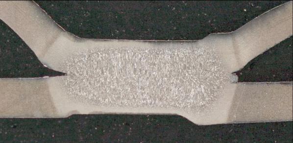
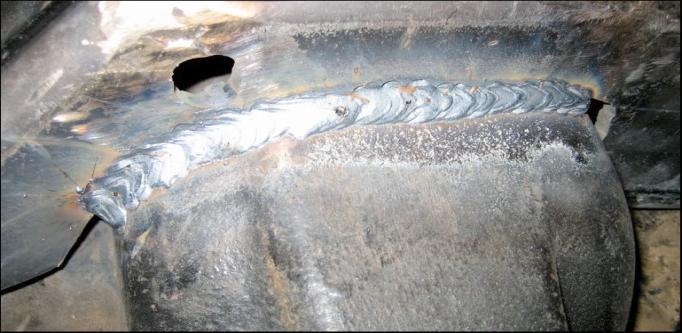


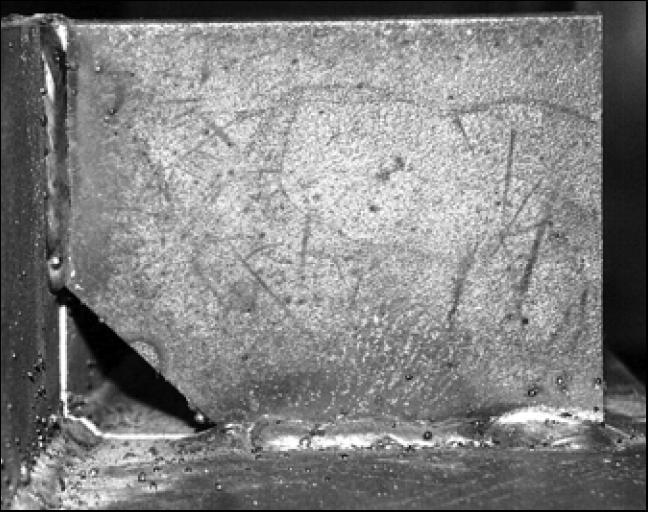
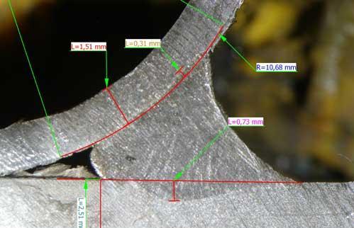
12 Weld Fabrication Stiffener weld Spot weld Fillet weld Fillet weld with porosity Flare bevel


13 Quality Issues Porosity and root opening Procedural errors Start and stop craters Undercut
14 Chain Link Clevis Plate Stress r u n t a il n o s e St r e s s (k s i) 4000 Clevis Weld Load average load tail run nose Distance along weld in


15 AISC/AWS Weld Design Elastic Method Ultimate Strength Method
16 Bracket Plate k 3/8 Bracket plate fillet welded to rectangular base plate fixed at edges Eq u iv a l e n t St re s s (k s i ) Weld attachment simulated with rigid constraints Weld force distribution compared to AISC Elastic method Weld Unit Load / Elastic Analysis FEA Distance along weld in
")
17 ASME Code Design Prescriptive provisions Specific weld joint details Flange attachment Opening details Weld details Types Sizes Allowable stresses Construction dependent Quality assurance Joint efficiencies Non Prescriptive Provisions Attachments Supports Machinery External loading Piping loads Impact Unique construction Non-circular openings Proprietary items Design by analysis (VIII-2) Lower design margin More restrictive quality assurance Explicit weld analysis rules


18 Explicit Modeling Solid Model Shell Model
19 Weld Load lb/in Non-Circular Opening O D x t k p la t e Pressurized bulkhead 29.5 in OD x 1.75 in thick with reinforced x rectangular opening Face bar attachment simulated with rigid constraints Weld force distribution checked against ASME Code opening requirements Face Bar Weld Load x 1. 5 f ac e b a r 3000 Y X Distance along weld in

20 Fatigue AWS/AISC
21 Fatigue ASME Code Ta ble 5.11 Ğ Weld Surface Fatigue-Strength-Reduction Factors Weld Surface Quality Levels (se e Table 5.12) Condition Condition Full penetration Partial Penetration Fillet Machined As-welded Final Surface Machined Final Surface As-welded NA NA Root NA 1.5 NA NA NA Toe machined NA NA 1.5 NA Toe as-welded NA NA 1.7 NA Root NA NA NA NA NA ASME Code Fatigue rules originate from the Coffin-Manson rule: the product of the plastic strain amplitude (half the strain range under reversed loading) produced by a cyclic loading and the number of cycles to crack initiation equals half the fracture ductility: where: p N RA f p N = f 2 = 1 2 Ln RA amplitude of plastic strain number of cycles to crack initiation Reduction of area from tensile test fracture ductility Taking the total strain amplitude as the sum of the plastic and elastic strain amplitudes and converting to stress by multiplying by the elastic modulus the cyclic stress amplitude to failure becomes S = E 4 N Ln RA + s For materials showing an endurance limit s is taken as the endurance limit S = E Ln N RA + S e B. F. Langer, Design of Pressure Vessels for Low Cycle Fatigue, J. of Basic Engineering, ASME Transactions, September Fatigue-Strength-Reduction Factor Notes: Ta ble 5.12 Ğ Weld Surface Fatigue-Strength-Reduction Factors Quality Level Volumetric examination only Definition Machined or ground weld that receives a full volumetric examination, and a surface that receives MT/PT examination and a VT examination. As-welded weld that receives a full volumetric examination, and a surface that receives MT/PT and VT examination Machined or ground weld that receives a partial volumetric examination, and a surface that receives MT/PT examination and VT examination As-welded weld that receives a partial volumetric examination, and a surface that receives MT/PT and VT examination Machined or ground weld surface that receives MT/PT examination and a VT examination (visual), but the weld receives no volumetric examination inspection As-welded or ground weld surface that receives MT/PT examination and a VT examination (visual), but the weld receives no volumetric examination inspection Weld has received a partial or full volumetric examination, and the surface has received VT examination, but no MT/PT examination VT examination only of the surface; no volumetric examination nor MT/PT examination Weld backsides that are non-definable and/or receive no examination. 1. Volumetric examination is RT or UT in accordance with Part MT/PT examination is magnetic particle or liquid penetrant examination in accordance with Part 7 3. VT examination is visual examination in accordance with Part 7.
Modeling Welded. ANSYS e-learning. June CAE Associates
 Modeling Welded Connections ANSYS e-learning Peter Barrett June 2013 2013 CAE Associates Outline The importance of weld stress prediction. Weld geometry and terminology. Failure due to fatigue. Methods
Using ncode DesignLife for Fatigue of Welds
 Using ncode DesignLife for Fatigue of Welds Jeff Mentley HBM Prenscia October 5-6, 2016 www.ncode.com Agenda 3 1. Overview of the Fatigue of Welds 2. Approaches for the Analysis of Fatigue of Seamwelds
Fatigue Testing and Life Estimates of Welded Flat Head Pressure Vessel Joints. Chris Hinnant Paulin Research Group Houston, TX
 Fatigue Testing and Life Estimates of Welded Flat Head Pressure Vessel Joints Chris Hinnant Paulin Research Group Houston, TX 1 Introduction 1. Test Specimens and Experimental Results 2. FEA Analysis and
Lecture 10: Fatigue of welds
 Kul-49.4350 Fatigue of Structures Lecture 10: Fatigue of welds 12.3.2016 Learning outcomes After the lecture, you understand fatigue phenomena in welded structures know the main influencing factors for
Fatigue Testing of Welded Flat Head Pressure Vessel Joints
 Fatigue Testing of Welded Flat Head Pressure Vessel Joints Chris Hinnant Paulin Research Group Houston, TX 2007 ASME PVP Conference San Antonio, TX July 25, 2007 1 Previous Experimental Work to Date Previous
Fatigue Analysis of a Welded Structure in a Random Vibration Environment
 Fatigue Analysis of a Welded Structure in a Random Vibration Environment ANSYS Users Conference Framingham, MA June 13, 2013 Michael Bak 2013 CAE Associates Outline Problem description: Life assessment
Fatigue of Welded Connections. Rodrigo Gutierrez
 Fatigue of Welded Connections Rodrigo Gutierrez Fatigue Fatigue is a process of accumulative damage produced dby the fluctuation of stress and strains even when both stress and strains are below the static
FEM STRESS CONCENTRATION FACTORS FOR FILLET WELDED CHS-PLATE T-JOINT
 Engineering Review Vol. 32, Issue 3, 147-155, 2012. 147 FEM STRESS CONCENTRATION FACTORS FOR FILLET WELDED CHS-PLATE T-JOINT S. * G. Turkalj Department of Engineering Mechanics, Faculty of Engineering,
Welding Efficiency & Learning Defects (W.E.L.D) Cards A
 Cards A") Welding Efficiency & Learning Defects (W.E.L.D) Cards 1033480-01A Ideal weld path and look for tee and butt joints Definition The proper weld filament, consistent path and fusion. Tee Joint V-Groove Joint
Welding Efficiency & Learning Defects (W.E.L.D) Cards 1033480-01A Ideal weld path and look for tee and butt joints Definition The proper weld filament, consistent path and fusion. Tee Joint V-Groove Joint
Repair and Retrofit of a Coke Drum Skirt Attachment Weld
 Repair and Retrofit of a Coke Drum Skirt Attachment Weld Mike Schmidt CHS Inc (406) 628-5475 mike.schmidt@chsinc.com Mahmod Samman, Ph.D., P.E. Houston Engineering Solutions (832) 512-0109 mms@hes.us.com
Burst Pressure Prediction of Cylindrical Shell Intersection
 Burst Pressure Prediction of Cylindrical Shell Intersection Liping Xue, G. E. O. Widera Marquette University Center for Joining and Manufacturing Assembly Milwaukee, Wisconsin 53201 Zhifu Sang Nanjing
Structural design criteria
 chapter three Structural design criteria Contents 3.1 Modes of failure... 3.2 Theories of failure... 3.3 Theories of failure used in ASME Boiler and Pressure Vessel Code... 3.4 Allowable stress limits
The fundamentals of weld joint design
 The fundamentals of joint design The performance of joints is determined by not only the load resisting cross sectional area of joint but also properties of region close to the metal i.e. heat affected
LINKING THEORY AND PRACTICE
 LINKING THEORY AND PRACTICE Structural Engineering and Advanced Analytical Modeling DESIGN CONSTRUCTION OPERATIONS RELIABILITY SAFETY SECURITY ANATECH CORP In 2013, we expanded our engineering expertise
Chapter 2 The Structural Hot-Spot Stress Approach to Fatigue Analysis
 Chapter 2 The Structural Hot-Spot Stress Approach to Fatigue Analysis 2.1 Field of Application The structural hot-spot stress approach applies to welded joints for which: the fluctuating principal stress
Design Development of Corrugated Bulkheads
 Design Development of Corrugated Bulkheads TSCF 2010 Shipbuilders Meeting 27 October 2010 Nippon Kaiji Kyokai 1 Topics Purpose of corrugated bulkheads Structural types of corrugated bulkheads Types of
Monday, May 05, Chapter 6. Fatigue Failure Resulting from Variable Loading. Dr. Mohammad Suliman Abuhaiba, PE
 Monday, May 05, 2014 Chapter 6 Fatigue Failure Resulting from Variable Loading 1 Chapter Outline Introduction to Fatigue in Metals Approach to Fatigue Failure in Analysis and Design Fatigue-Life Methods
EFFECT OF WELDING SEQUENCES ON RESIDUAL STRESS IN SINGLE PASS BUTT WELDING OF SAE 1020 STEEL
 EFFECT OF WELDING SEQUENCES ON RESIDUAL STRESS IN SINGLE PASS BUTT WELDING OF SAE 1020 STEEL Teke Sumit Sudhakar 1, Prof. P.P.Powar 2, Prof. R.R.Gad 3. 1 ME (CAD/CAM/CAE), 2 Associate Professor, 3 Assistant
Observations Related to the Master SN Method in the ASME Division 2 Rewrite Project
 Observations Related to the Master SN Method in the ASME Division 2 Rewrite Project ASME BPVC Code Week Atlanta, GA February 2007 Chris Hinnant Paulin Research Group Houston, TX Summary The following are
CH 6: Fatigue Failure Resulting from Variable Loading
 CH 6: Fatigue Failure Resulting from Variable Loading Some machine elements are subjected to statics loads and for such elements, statics failure theories are used to predict failure (yielding or fracture).
E APPENDIX. The following problems are intended for solution using finite element. Problems for Computer Solution E.1 CHAPTER 3
 E APPENDIX Problems for Computer Solution The following problems are intended for solution using finite element analysis software. In general, the problems associated with Chapters 3, 4, and 9 can be solved
HYBRID COMPOSITE REPAIR for OFFSHORE RISERS
 HYBRID COMPOSITE REPAIR for OFFSHORE RISERS O. O. Ochoa and C. Alexander Mechanical Engineering Texas A&M University College Station, TX 77840 oochoa@tamu.edu SUMMARY An innovative design based on integrated
Planning Advisory Notice
 This Planning Advisory Notice (PAN) is a follow up to the PAN from the March/April issue. In that PAN we discussed some of the codes, standards, and specifications that apply to proper welding design,
Fast quench problems and how they damage coke drums
 Fast quench problems and how they damage coke drums Coke Drum Reliability Workshop Galveston, Texas March 24, 2009 Richard Boswell, P.E. Stress Engineering Services, Inc Principal richard.boswell@stress.com
FINITE ELEMENT MODELING TECHNIQUES OF 3D WELDED JOINTS THE STRUCTURAL HOT SPOT APPROACH
 FINITE ELEMENT MODELING TECHNIQUES OF 3D WELDED JOINTS THE STRUCTURAL HOT SPOT APPROACH Keurrie Cipriano Goes, keurrie.goes@arvinmeritor.com ArvinMeritor do Brasil Sistemas Automotivos Commercial Vehicle
Requirements for bending and flaring of piping Objective, target group and warrant...3 Requirements...3 Cold Bending...4 Induction Bending...
 Technical and professional requirements, TR1969, Final Ver. 2, Valid from 2006-09-29 Publisher/follow-up: Chiefengineer Materials Technology Classification: Open Validity area: Statoil Group/All locations/all
Study the pattern of J-profile along the crack front through 3D finite element analysis
 Page 16 Study the pattern of J-profile along the crack front through 3D finite element analysis Abstract: Badrun Nahar Hamid a*, Michale J Baker b a Principal Scientific Officer, Atomic Energy Research
MOMENT RESISTING CONNECTION WITH SIDEPLATE (GEOMETRIC ASPECTS)
") 13 th World Conference on Earthquake Engineering Vancouver, B.C., Canada August 1-6, 2004 Paper No. 194 MOMENT RESISTING CONNECTION WITH SIDEPLATE (GEOMETRIC ASPECTS) Ardeshir DEYLAMI 1, and R. ASHRAF
13 th World Conference on Earthquake Engineering Vancouver, B.C., Canada August 1-6, 2004 Paper No. 194 MOMENT RESISTING CONNECTION WITH SIDEPLATE (GEOMETRIC ASPECTS) Ardeshir DEYLAMI 1, and R. ASHRAF
MACHINES DESIGN SSC-JE STAFF SELECTION COMMISSION MECHANICAL ENGINEERING STUDY MATERIAL MACHINES DESIGN
 1 SSC-JE STAFF SELECTION COMMISSION MECHANICAL ENGINEERING STUDY MATERIAL C O N T E N T 2 1. MACHINE DESIGN 03-21 2. FLEXIBLE MECHANICAL ELEMENTS. 22-34 3. JOURNAL BEARINGS... 35-65 4. CLUTCH AND BRAKES.
Fatigue failure & Fatigue mechanisms. Engineering Materials Chedtha Puncreobutr.
 Fatigue failure & Fatigue mechanisms Engineering Materials 2189101 Department of Metallurgical Engineering Chulalongkorn University http://pioneer.netserv.chula.ac.th/~pchedtha/ Fracture Mechanism Ductile
Course: Quality Assurance Module 5 Welders/Welding personnel
 Version 1.0 2010.11.02 1 of 7 Course: Quality Assurance Module 5 Welders/Welding personnel Version 1.0 2010.11.02 2 of 7 Table of Contents MODULE 5...3 Surface inspection on cracks and other surface imperfections
Fast quench problems and how they damage coke drums
 Coke Drum Reliability Workshop Fast quench problems and how they damage coke drums Rio De Janeiro, Brazil August 7, 2009 Presented by: Julian Bedoya Julian.bedoya@stress.com Prepared by: Richard Boswell
Contents. Local (Structural) Stress Based Fatigue Design. Nominal Stress Ranges. Fatigue Design. Fatigue stress on a gusset
 Stress Based Fatigue Design. Nominal Stress Ranges. Fatigue Design. Fatigue stress on a gusset") Contents Local (Structural) Stress Based Brief Review of Nominal Stress Based Structural Stress Based -Fatigue Assessment of Welded Joints- Department of Civil Engineering Tokyo Institute of Technology
Contents Local (Structural) Stress Based Brief Review of Nominal Stress Based Structural Stress Based -Fatigue Assessment of Welded Joints- Department of Civil Engineering Tokyo Institute of Technology
Basic principle and methodology of weld joints design
 Basic principle and methodology of weld joints design This chapter describes basic principle and methodology of weld joints design for static and dynamic loading to develop groove and fillet weld joints
SENSE Level I Welding Process Certification Test Module 3: Drawing and Welding Symbol Interpretation
 Multiple Choice: Circle the letter which corresponds to the correct answer. 1. The primary element of any welding symbol is referred to as the a) arrow. b) tail. c) reference line. d) weld symbol. 2. Information
STRUCTURAL ANALYSIS FOR STRENGTH AND FATIGUE LIFE OF HALF COUPLING WELDMENT FOR LARGE COOLING WATER PIPES
 STRUCTURAL ANALYSIS FOR STRENGTH AND FATIGUE LIFE OF HALF COUPLING WELDMENT FOR LARGE COOLING WATER PIPES KUNAL S BHATT, SARBJEET SINGH SANDHU, TARUN KUMAR SHARMA ITER-India, Institute for Plasma Research,
Module 4 Design for Assembly
 Module 4 Design for Assembly Lecture 2 Design for Welding-I Instructional Objective By the end of this lecture, the student will learn: (a) how a weld joint should be designed to improve the joint performance,
APPLICATION OF HIGHER-STRENGTH HULL STRUCTURAL THICK STEEL PLATES IN CONTAINER CARRIERS
 Guide for Application of Higher-Strength Hull Structural Thick Steel Plates in Container Carriers GUIDE FOR APPLICATION OF HIGHER-STRENGTH HULL STRUCTURAL THICK STEEL PLATES IN CONTAINER CARRIERS FEBRUARY
TECHNICAL GUIDE FATIGUE RESISTANCE
 TECHNICAL GUIDE FATIGUE RESISTANCE FATIGUE RESISTANCE OF BISALLOY STEEL Bisalloy Steels has recently introduced a new product nomenclature. The following table details the grade equivalents. Note: Only
Determination of the residual stress distribution of steel bridge components by modelling the welding process
 EUROSTEEL 2017, September 13 15, 2017, Copenhagen, Denmark Determination of the residual stress distribution of steel bridge components by modelling the welding process Evy Van Puymbroeck*,a, Wim Nagy
9. VACUUM TANK 9. VACUUM TANK
 9. VACUUM TANK This system constitutes the external part of the solenoid cryostat. The vacuum tank, made of stainless steel, is cantilevered from the central ring of the barrel yoke. It houses and supports
FEA & Experimental Approach for Weld Fatigue Stress Evaluation of Pressure Vessel Nozzle Joint
 FEA & Experimental Approach for Weld Fatigue Stress Evaluation of Pressure Vessel Nozzle Joint Amol A. Kamble 1, Prof. Dr. D. S. More 2 1Dr. D. Y. Patil School of Engineering, Lohegaon, Pune. India Savitribai
SEISMIC PERFORMANCE OF SCBF BRACED FRAME GUSSET PLATE CONNECTIONS
 4th International Conference on Earthquake Engineering Taipei, Taiwan October 12-13, 2006 Paper No. 80 SEISMIC PERFORMANCE OF SCBF BRACED FRAME GUSSET PLATE CONNECTIONS Charles W. Roeder 1, Dawn E. Lehman
Effect of Spray Quenching Rate on Distortion and Residual Stresses during Induction Hardening of a Full-Float Truck Axle
 Effect of Spray Quenching Rate on Distortion and Residual Stresses during Induction Hardening of a Full-Float Truck Axle Zhichao (Charlie) Li and B. Lynn Ferguson DANTE SOFTWARE, Cleveland, OH 44130, USA
Evaluation of Pipe Weld NDE Indications
 Evaluation of Pipe Weld NDE Indications Brasse, Markus Westinghouse Electric Germany Dudenstrasse 44, D-68167 Mannheim, Germany Markus.Brasse@de.westinghouse.com ABSTRACT This paper discusses the evaluation
DETERMINATION OF FAILURE STRENGTH OF CURVED PLATE WELD JOINT USING FINITE ELEMENT ANALYSIS
 Int. J. Mech. Eng. & Rob. Res. 2012 Chetan S Baviskar et al., 2012 Research Paper ISSN 2278 0149 www.ijmerr.com Vol. 1, No. 3, October 2012 2012 IJMERR. All Rights Reserved DETERMINATION OF FAILURE STRENGTH
Residual Stresses and Distortion in Weldments
 Residual Stresses and Distortion in Weldments By: Aziz Shafiei Residual Stresses 1 Causes of Residual Stresses Residual stresses in metal structures occur for many reasons during various manufacturing
2. Fatigue Strength of Welded Structural Components
 2. Fatigue Strength of Welded Structural Components Contents 1. Introduction 2. Fatigue Design Curve 3. Strength Categories of Joints and Their Basic Allowable Stress Ranges 4. Correction Factor for Basic
C. PROCEDURE APPLICATION (FITNET)
") C. PROCEDURE APPLICATION () 266 INTRODUCTION INPUTS SPECIAL OPTIONS 267 INTRODUCTION INTRODUCTION The fatigue module provides a series of assessment procedures or routes for evaluating the effect of cyclic
C. PROCEDURE APPLICATION () 266 INTRODUCTION INPUTS SPECIAL OPTIONS 267 INTRODUCTION INTRODUCTION The fatigue module provides a series of assessment procedures or routes for evaluating the effect of cyclic
MANDATORY APPENDIX 2 RULES FOR BOLTED FLANGE CONNECTIONS WITH RING TYPE GASKETS
 ASME BPVC.VIII.1-2017 2-1 2-2 MANDATORY APPENDIX 2 RULES FOR BOLTED FLANGE CONNECTIONS WITH RING TYPE GASKETS ð17þ 2-1 SCOPE (a) The rules in Mandatory Appendix 2 apply specifically to the design of bolted
Investigation of Structural Steel Webs for Punching Shear
 Journal of Civil Engineering and Architecture 9 (2015) 1126-1136 doi: 10.17265/1934-7359/2015.09.013 D DAVID PUBLISHING Investigation of Structural Steel Webs for Punching Shear Mustafa Mahamid 1 and Adeeb
Designer engineering specialisation (M4, M5 och M6)
") Internationell svetskonstruktör, IWSD - Kursprogram Designer engineering specialisation (M4, M5 och M6) Module 4: DESIGN OF WELDED JOINTS / Utformning av svetsförband 4.1 Categories of welded joints/olika
Internationell svetskonstruktör, IWSD - Kursprogram Designer engineering specialisation (M4, M5 och M6) Module 4: DESIGN OF WELDED JOINTS / Utformning av svetsförband 4.1 Categories of welded joints/olika
IACS Common Structural Rules for Double Hull Oil Tankers, January Background Document
 IACS Common Structural Rules for Double Hull Oil Tankers, January 2006 Background Document SECTION 9/2 DESIGN VERIFICATION STRENGTH ASSESSMENT (FEM) NOTE: - This TB is published to improve the transparency
Table of Contents Page No.
 Table of Contents Page No. Personnel... iii Foreword...v List of Tables...xii List of Figures... xiii 1. General Requirements...1 1.1 Scope...1 1.2 Approval...1 1.3 Definitions...1 1.4 Welding Symbols...1
Full-scale Testing of the Cast Steel Yielding Brace System
 Full-scale Testing of the Cast Steel Yielding Brace System M.G. Gray, C. Christopoulos & J.A. Packer Department of Civil Engineering, University of Toronto, Toronto, Canada ABSTRACT: The cast steel Yielding
The designs, depending upon the methods used, may be classified as follows:
 Definition Machine Design is the creation of new and better machines and improving the existing ones. A new or better machine is one which is more economical in the overall cost of production and operation.
CHAPTER 3 FINITE ELEMENT SIMULATION OF WELDING
 47 CHAPTER 3 FINITE ELEMENT SIMULATION OF WELDING 3.1 INTRODUCTION Though welding process has many distinct advantages over other joining processes, it suffers from some major disadvantages like the evolution
Stress Evaluation of a Typical Vessel Nozzle Using PVRC 3D Stress Criteria: Guidelines for Application
 Stress Evaluation of a Typical Vessel Nozzle Using PVRC 3D Stress Criteria: Guidelines for Application Michael A. Porter Dynamic Analysis Leawood, Kansas 66206 Dennis H. Martens Black & Veatch Pritchard
FATIGUE ASSESSMENT OF SHIP STRUCTURES * * *
 No.56 No.56 (July 1999) FATIGUE ASSESSMENT OF SHIP STRUCTURES * * * Recom. 56.1 IACS Rec. 1999 FATIGUE ASSESSMENT OF SHIP STRUCTURES ************ TABLE OF CONTENTS 1. GENERAL 2. DETERMINATION OF THE LONG
PVP Proceedings of the ASME 2014 Pressure Vessels & Piping Conference PVP2014 July 20-24, 2014, Anaheim, California, USA
 Proceedings of the ASME 2014 Pressure Vessels & Piping Conference PVP2014 July 20-24, 2014, Anaheim, California, USA PVP2014-28958 Writing and Reviewing FEA Reports Supporting ASME Section VIII, Division
FATIGUE FAILURES IN INDUSTRY CASE STUDIES
 INTERNATIONAL DESIGN CONFERENCE - DESIGN 2002 Dubrovnik, May 14 17, 2002 FATIGUE FAILURES IN INDUSTRY CASE STUDIES Ž. Domazet and T. Piršic Keywords: Fatigue cracks and failures, repair welding, FEM 1.
Reinforced Thermoset Plastic Corrosion-Resistant Equipment
 ASME RTP-1 2007 (Revision of ASME RTP-1 2005) Reinforced Thermoset Plastic Corrosion-Resistant Equipment AN AMERICAN NATIONAL STANDARD Three Park Avenue New York, NY 10016 Date of Issuance: April 9, 2008
ANSYS CALCULATIONS REPORT Outer Vessel Ansys outer vessel Sylvain ANTOINE Amaury PORHIEL - Rev C
 SUMMARY 1. REVISION RECORD... 2 2. ABSTRACT... 2 3. FEA Software... 2 4. USER S DESIGN SPECIFICATION... 2 5. FEA MODEL GEOMETRY AND MESHING... 3 6. FEA MODEL CONTACT AND BOUNDARIES CONDITIONS... 4 7. FEA
Development of bimodal grain structures in microalloyed steels:
 Development of bimodal grain structures in microalloyed steels: Niobium and titanium are added to high strength low alloy (HSLA) steels to provide grain boundary pinning precipitates to help produce the
Design Development of Corrugated Bulkheads
 Design Development of Corrugated Bulkheads Hayato Suga Tatsuya Hayashi Shinichiro Ishimaru Koki Hirano Tsubasa
COMPARISON OF LIMIT LOAD, LINEAR AND NONLINEAR FE ANALYSIS OF A TYPICAL VESSEL NOZZLE
 COMPARISON OF LIMIT LOAD, LINEAR AND NONLINEAR FE ANALYSIS OF A TYPICAL VESSEL NOZZLE Michael A. Porter Dynamic Analysis 20706 Mill Road Lenexa, Kansas 66220 913-422-5998 mike@dynamicanalysis.com Wolf
A REVIEW ON DESIGN AND ANALYSIS OF PRESSURE VESSEL
 A REVIEW ON DESIGN AND ANALYSIS OF PRESSURE VESSEL 1 Umbarkar Bhagyashri B. 2. Prof. Hredeya Mishra 1 Student, Dept. of Mechanical Engg.,Jaihind college of Engg. & Technology, Maharashtra, India. Um.bhagyashri@gmail.com
PART UF REQUIREMENTS FOR PRESSURE VESSELS FABRICATED BY FORGINGS
 p 1 of 6 UF-1 UF-12 PART UF REQUIREMENTS FOR PRESSURE VESSELS FABRICATED BY FORGING the test temperature be higher than 20 F ( 29 C). Certification is required. An ultrasonic examination shall be made
Common Operating Problems
 SYDNEY Pressure Vessels Field Manual Common Operating Problems and Practical Solutions Maurice Stewart Oran T. Lewis AMSTERDAM BOSTON HEIDELBERG LONDON NEW YORK OXFORD PARIS SAN DIEGO SAN FRANCISCO SINGAPORE
COMPARISON OF LIMIT LOAD, LINEAR AND NONLINEAR FE ANALYSES OF STRESSES IN A LARGE NOZZLE-TO-SHELL DIAMETER RATIO APPLICATION
 COMPARISON OF LIMIT LOAD, LINEAR AND NONLINEAR FE ANALYSES OF STRESSES IN A LARGE NOZZLE-TO-SHELL DIAMETER RATIO APPLICATION Michael A. Porter Dynamic Analysis 2815 Stratford Road Lawrence, Kansas 6649
Cold Spray Developments at UTRC
 Hamilton Sundstrand Sikorsky Pratt & Whitney UTC Fire & Security Otis Elevator UTC Power Carrier Cold Spray Developments at UTRC Aaron Nardi United Technologies Research Center Cold Spray Action Team (CSAT)
ME -215 ENGINEERING MATERIALS AND PROCESES
 ME -215 ENGINEERING MATERIALS AND PROCESES Instructor: Office: MEC325, Tel.: 973-642-7455 E-mail: samardzi@njit.edu PROPERTIES OF MATERIALS Chapter 3 Materials Properties STRUCTURE PERFORMANCE PROCESSING
ACHIEVING DUCTILE BEHAVIOR OF MOMENT CONNECTIONS PART II
 Beam Seismic Design Panel zone ACHIEVING DUCTILE BEHAVIOR OF MOMENT CONNECTIONS PART II The results of additional tests provide further confirmation that weld metal toughness is key in achieving ductile
Pressure Vessel Engineering Ltd. ASME Calculations - CRN Assistance - Vessel Design - Finite Element Analysis
 PVEng Pressure Vessel Engineering Ltd. ASME Calculations - CRN Assistance - Vessel Design - Finite Element Analysis Design Conditions Code: ASME VIII-1 Year: 2010 Finite Element Analysis Report - VIII-1
A STUDY OF FINE BLANKING PROCESS BY FEM SIMULATION. G. Fang, P. Zeng
 Key Engineering Materials Vols. 261-263 (2004) pp 603-608 Online available since 2004/Apr/15 at www.scientific.net (2004) Trans Tech Publications, Switzerland doi:10.4028/www.scientific.net/kem.261-263.603
Design and Analysis of Mixing Sphere in Start-up System of Supercritical Boilers
 Design and Analysis of Mixing Sphere in Start-up System of Supercritical Boilers V. Malleswara Rao, AR. Veerappan, T. Christo Michael & C. Kathirvelu Deptt. of Mechanical Engineering, National Institute
Certificate of Accreditation
 PERRY JOHNSON LABORATORY ACCREDITATION, INC. Certificate of Accreditation Perry Johnson Laboratory Accreditation, Inc. has assessed the Laboratory of: (Hereinafter called the Organization) and hereby declares
Static Analysis of Tube to Header Weld Joint Configurations
 Static Analysis of Tube to Header Weld Joint Configurations T. Shyju P G -Scholar, Manufacturing Engineering University College of Engineering, BIT campus Dr. T. Senthil Kumar Dean, University College
Welding simulations: assessment of welding residual stresses and post weld heat treatment
 Welding simulations: assessment of welding residual stresses and post weld heat treatment Etienne Bonnaud and Jens Gunnars, Inspecta Technology AB Third Nordic Conference on Design and Fabrication of Welded
Uses of Abaqus/Standard in Failure Analysis
 Uses of Abaqus/Standard in Failure Analysis Matthew T. Kenner, P.E., John A. Wilkinson, P.E., Michael E. Stevenson, Ph.D., P.E., and Michael D. Hayes, Ph.D., P.E. Engineering Systems Inc. www.esi-website.com
ANSYS Pressure Equipment Module
 ANSYS Pressure Equipment Module ASME PVP 2007 Janet Wolf Sr. Application Engineer 2007 ANSYS, Inc. All rights reserved. 1 ANSYS, Inc. Proprietary Agenda Overview of the module Modelling the components
A Practical Design Guide for Welded Connections Part 1 Basic Concepts and Weld Symbols
 A Practical Design Guide for Welded Connections Part 1 Basic Concepts and Weld Symbols by James Doane, PhD, PE Course Overview This course is divided into 2 parts. Though it provides some basic concepts
Fundamentals p. 1 Mechanical Engineering Design in Broad Perspective p. 3 An Overview of the Subject p. 3 Safety Considerations p.
 Fundamentals p. 1 Mechanical Engineering Design in Broad Perspective p. 3 An Overview of the Subject p. 3 Safety Considerations p. 5 Ecological Considerations p. 9 Societal Considerations p. 11 Overall
GENERAL CONTENTS SECTION I - NUCLEAR ISLAND COMPONENTS
 - June 2013 Addendum GENERAL CONTENTS SECTION I - NUCLEAR ISLAND COMPONENTS SUBSECTION "A" : GENERAL RULES SUBSECTION "B" : CLASS 1 COMPONENTS SUBSECTION "C" : CLASS 2 COMPONENTS SUBSECTION "D" : CLASS
WELD - STATIC AND FATIGUE STRENGTH -III
 32 WELD - STATIC AND FATIGUE STRENGTH -III 1.0 INTRODUCTION A component or a structure, which can withstand a single application of load, may fracture if the same load is applied a large number of times.
Prediction of Residual Stresses after Local Post-Weld Heat Treatment
 GROUP SPONSORED PROJECT OUTLINE PR 21964 July 2013 Summary Residual stresses caused by fabrication or repair welding can affect the resistance to fracture or corrosion damage of a thick component. Post-weld
A Fatigue Prediction Method for Spot Welded Joints
 A Fatigue Prediction Method for Spot Welded Joints H. Kang 1, A.K. Khosrovaneh 2, M. Hu 1, U. De Souza 2 1 The University of Michigan-Dearborn 2 General Motors Company Table of Contents Objective Materials
CONTENTS. Foreword... xiii Statements of Policy... xv Personnel... xvii Organization of Section III... xxvii Summary of Changes...
 CONTENTS Foreword... xiii Statements of Policy... xv Personnel... xvii Organization of Section III... xxvii Summary of Changes... xxxi Article NB-1000 Introduction... 1 NB-1100 Scope... 1 NB-1110 Aspects
CHAPTER 9 INFLUENCE OF RESIDUAL STRESSES ON THE FAILURE PRESSURE OF CYLINDRICAL VESSELS
 150 CHAPTER 9 INFLUENCE OF RESIDUAL STRESSES ON THE FAILURE PRESSURE OF CYLINDRICAL VESSELS In the design of pressure vessels, evaluation of failure pressure that a cylindrical pressure vessel can withstand
Lecture 1: Introduction to Mechanical design consideration for process equipment
 Lecture 1: Introduction to Mechanical design consideration for process equipment Process Equipment Design I (P.E.D. I) mainly deals with Chemical Engineering principles and theory whereas Process Equipment
RESULTS OF FEA ANALYSES AT NOZZLE/SHELL JUNCTIONS SUBJECTED TO EXTERNAL LOADS
 RESULTS OF FEA ANALYSES AT NOZZLE/SHELL JUNCTIONS SUBJECTED TO EXTERNAL LOADS Steven R. Massey Charlie S. Hsieh Black & Veatch Pritchard Inc. Black & Veatch Pritchard Inc. 10950 Grandview Drive 10950 Grandview
Specification for Welding Earthmoving, Construction, and Agricultural Equipment
 Key Words Structural welds, field repair, welding, earthmoving equipment, construction equipment, agricultural equipment AWS D14.3/D14.3M:2005 An American National Standard Approved by American National
FINITE ELEMENT ANALYSIS OF REINFORCED CONCRETE BRIDGE PIER COLUMNS SUBJECTED TO SEISMIS LOADING
 FINITE ELEMENT ANALYSIS OF REINFORCED CONCRETE BRIDGE PIER COLUMNS SUBJECTED TO SEISMIS LOADING By Benjamin M. Schlick University of Massachusetts Amherst Department of Civil and Environmental Engineering
D. Y. Abebe 1, J. W. Kim 2, and J. H. Choi 3
 Steel Innovations Conference 213 Christchurch, New Zealand 21-22 February 213 HYSTERESIS CHARACTERSTICS OF CIRCULAR PIPE STEEL DAMPER USING LYP225 D. Y. Abebe 1, J. W. Kim 2, and J. H. Choi 3 ABSTRACT
Increased plastic strains in containment steel liners due to concrete cracking and discontinuities in the containment structure
 Increased plastic strains in containment steel liners due to concrete cracking and discontinuities in the containment structure Patrick Anderson 1) and Ola Jovall 2) 1) Division of Structural Engineering,
Improving Structural Performance of Parts through Moldex3D FEA Interface
 Improving Structural Performance of Parts through Moldex3D FEA Interface Sagar Bhamare, Ph.D. Mechanical Engineer/ FEA Analyst (M: 513-503-0576, Email: sbhamare@innovaengineering.com) Terence Smith Senior
Reinforced Thermoset Plastic Corrosion-Resistant Equipment
 ASME RTP-1 2013 (Revision of ASME RTP-1 2011) Reinforced Thermoset Plastic Corrosion-Resistant Equipment AN AMERICAN NATIONAL STANDARD ASME RTP-1 2013 (Revision of ASME RTP-1 2011) Reinforced Thermoset
Fatigue strength of knuckle joints - a key parameter in ship design D. Beghin Marine Division, Bureau Veritas, Paris, France
 Fatigue strength of knuckle joints - a key parameter in ship design D. Beghin Marine Division, Bureau Veritas, Paris, France Abstract Structural integrity of knuckle joints in inner hull for double hull
Overview of Presentation. SCBFs are Conceptually Truss Structures
 Ultimate Strength and Inelastic Behavior of Braced Frame Gusset Plate Connections Charles W. Roeder University of Washington Department of Civil and Environmental Engineering Seattle, WA 98195 Structural