Resistance Temperature Detectors
|
|
|
- Louisa Booker
- 5 years ago
- Views:
Transcription

1 Resistance Temperature Detectors INTRODUCTION For high-accuracy temperature measurements in a variety of industrial and commercial air and gas applications, Durex Industries offers RTD s of multiple elements and styles. Durex RTD s are available with an assortment of connections, mounting hardware, and enclosures to suit harsh chemical, immersion, and other heavy-duty requirements. Sealed leadwire transitions eliminate contamination. Multiple sensing elements can be located at various points for precise temperature control. Design Features: Platinum, Nickel, or Nickel Iron elements 2, 3, or 4-wire styles High pressure applications up to 5000 psi Optional sanitary-grade stainless steel hardware Temperatures up to 1500 F (816 C) Optional braiding or armor cable shielding Typical Applications: Food Service Semiconducting Packaging Hot Melt Dispensing Vacuum Sealing and Forming Automotive Medical / Laboratory Settings 1
2 Resistance Temperature Detectors SPECIFICATIONS Unless otherwise specified, Durex s RTD assemblies include photo-lithographically structured, high-purity platinum thin-film elements laser trimmed to precise resistance values. These sensors feature brief response times, excellent long term stability, low self heating and excellent resistance to vibration and temperature shocks. Thermal Response Time The response time T 0.63 is the time the sensors need to respond to 63% of the change in temperature. The response time depends on the sheath dimensions, but can be as low as 1.2 seconds. Long Term Stability The change of ohmage after 1,000 hours at maximum operating temperature amounts to less than 0.03%. Self Heating To measure the resistance, an electric current has to flow through the element, which will generate heat energy resulting in errors of measurement. To minimize error, the testing current should be kept low (approximately 1mA for Pt-100). Temperature error ΔT = RI²/E with: E = self-heating coefficient in mw/k R = resistance in kω I = measuring current in ma The self-heating coefficient (E) for the standard elements used in Durex RTD assemblies is 4 mw/k in air and 40 mw/k in water. Measuring Current Measurement current causes heating of the platinum thin-film sensor. The resulting temperature error is given by: ΔT = P/E with the power loss P = I 2 R, and the self-heating coefficient E in mw/k. The amount of thermal transfer from the sensor in the application determines how much measuring current can be applied. There is no bottom limit of the measurement current with platinum thin-film. The measurement current depends highly on the application in use. We recommend at: 100Ω: typically 1mA, maximum 5mA 500Ω: typically 0.5mA, maximum 3mA 1000Ω: typically 0.3mA, maximum 2mA 2000Ω: typically 0.2mA, maximum 1mA Nominal Values The nominal or rated value of the sensor is the target value of the sensor resistance at 0 C. The temperature coefficient α is defined as α = R (K -1 ) and has the numerical value of K R 0 according to DIN IEC R 0 R100 - R In practice, a value multiplied by 10 6 is often entered: TCR = 10 6 x 0 x (ppm/k) R 0 In this case, the numerical value is 3850 ppm/k. 2
3 SPECIFICATIONS Temperature Characteristic Curve Resistance Temperature Detectors The temperature characteristic curve determines the dependence of the electrical resistivity on the temperature. The following definition of the temperature curve according to DIN EN standard applies: -200 to 0 C R(t) = R 0 [1+(A*t)+(B*t 2 )+C(t-100)t 3 ] 0 to 250 C R(t) = R 0 [1+(A*t)+(B*t 2 )] 3 t[k] B Platinum (3850 ppm/k): A = * 10-3 [ C -1 ] B = * 10-7 [ C -2 ] C = * [ C -4 ] 2 Platinum (3750 ppm/k): A = * 10-3 [ C -1 ] B = * 10-7 [ C -2 ] C = -6 * [ C -4 ] R 0 = Resistance value in ohm at 0 C t = temperature in accordance with ITS 90 Tolerance Classes The temperature sensors are divided into classes according to their limit deviations: Class ± limit deviations in C (K) IST AG designation Temperature range DIN 60751, class B x T B -200 C to 850 C DIN 60751, class A x T A -90 C to 300 C ⅓ DIN 60751, class B x T Y -50 C to 150 C 1 Tolerance Field Y A t[ C] T is the numerical value of the temperature C without taking into account either negative or positive signs. Special selection of sensors upon request (pairings, groupings, special tolerances). Calibration Services Durex RTD calibrations are fully traceable to the National Institute of Standards and Technology (NIST) and are useful for defining the exact temperature coefficient of the sensor. For sensor applications below 32 F (0 C), a cryogenic range calibration is recommended. Certificates are supplied with all calibrations. Printed tables of interpolated values are only supplied with cryogenic range calibrations. RTD Assembly Temperature Ranges Style: R1L, R2L, The maximum rated temperature for these four styles is 500 F. Typically they are constructed R3L, R4L with Teflon leads and the lead end is protected with an epoxy seal. This epoxy seal provides a moisture resistant barrier. Style: R1M, R2M, R3M, R4M The maximum rated temperature for these next four styles is 900 F. They are constructed with high temperature fiberglass insulated conductors. The lead end is sealed and protected with a high temperature cement. Style: R1P, R2P, R3P, R4P The maximum rated temperature for these last four styles is 1200 F. Their construction features highly compacted magnesium oxide insulation. Nickel conductors provide for extended temperature ratings and harsh environments. 3
4 SPECIFICATIONS Available RTD Elements Resistance Temperature Detectors Element Temperature Coefficient Tolerance at 0 C A 100 ohm Platinum % B 100 ohm Platinum % C 100 ohm Platinum % D 500 ohm Platinum % E 1000 ohm Platinum % F 2000 ohm Platinum % G 100 ohm Platinum % H 100 ohm Platinum % J 120 ohm Nickel % K 604 ohm Nickel Iron % Wiring Diagrams R T 2 Wire, Wheatstone Bridge R L1 R L2 R 2 M R 1 R 2 The meter reads R T + the two lead resistances R L1 and R L2 4 Wire, Compensated Wheatstone Bridge R L4 R L3 R L1 R L2 M Supply Supply In this type R L3 and R L4 appear in one arm of the bridge. R L1 and R L2 appear in the other. Errors are R L1 +R L2 -R L3 -R L4 R T 3 Wire, Wheatstone Bridge R L3 R L1 R L2 M Supply One lead resistance is included in each of the two arms of the bridge. The errors reduce to R L1 - R L2 4 Wire, Connected High Impedance Voltage Measurement Supply Errors can be made negligible by having a very high input impedance amplifier. E 5 Internal Wiring Diagram A 1 B 2 C 3 A 1 B 2 F A Wire 3 Wire B 2 C A 3 1 B 2 D 4 4 Wire Compensated 4 Wire Connected Definitions L s B s A s L dimensions are specified in whole inches and a single alpha character which represents a fraction. Enter the three digit code as follows: B dimensions are specified in fractions from ⅛ to 1. Use the single alpha character to indicate the tip length. Enter the code as follows: A dimensions are specified in whole inches only. Enter the three digit code as follows: Fractional Letter ¹/₁₆ A ¹¹/₁₆ L ⅛ B ¾ M ³/₁₆ C ¹³/₁₆ N ¼ D ⅞ P ⁵/₁₆ E ¹⁵/₁₆ R ⅝ 10K ⅜ F 1 S 4 ½ 04H ⅛ B ⅝ K ⁷/₁₆ G 0 No 6 ¼ 06D 15 ⅜ 15F ¼ D ¾ M ½ H Fraction 7 ⅞ 07P 17 ¾ 17M ⅜ F ⅞ P ⁹/₁₆ J 9 ⅝ 09K 22 ⅛ 22B ½ H 1 S ⅝ K 4
5 RTD WITH LEADWIRE Resistance Temperature Detectors L Specify in inches. (Enter 10H for 10 ½ ) Diameter A Specify in inches (Enter 100 for 100 ) ¼ Stripped Length STYLE R1L R1M R1L - Maximum Temperature 500 F R1M - Maximum Temperature 900 F A B D E G J K Table 1: Element 100 ohm Curve Class B Platinum 100 ohm Curve Class A Platinum 500 ohm Curve Class B Platinum 1000 ohm Curve Class B Platinum 100 ohm Curve Class B Platinum 120 ohm Curve Nickel (R1L Only) 604 ohm Curve Nickel Iron (R1L Only) Table 2: Wiring Configuration A Single, 2 Wire B Single, 3 Wire (Minimum sheath diameter.156 ) C Single, 4 Wire (Minimum sheath diameter.188 ) D Dual, 4 Wire (Minimum sheath diameter.188 ) E Dual, 6 Wire (Minimum sheath diameter.250 ) Table 3: Sheath Material Stainless Steel Stainless Steel 8 Inconel 600 B V C D F Table 4: Sheath Diameter.125 or ⅛ O.D..156 or ⁵/₃₂ O.D..188 or ³/₁₆ O.D..250 or ¼ O.D..375 or ⅜ O.D. Table 5: Sheath Length ( L ) Specify in inches. See table on page 4 for codes. Table 6: Lead Length ( A ) Specify in inches. See table on page 4 for codes. A B C D E F G J K M Table 7: Leadwire Stranded Fiberglass Singles Stranded Fiberglass with Overall Fiberglass Jacket Stranded Fiberglass with Stainless Steel Overbraid Stranded Fiberglass with Stainless Steel Armor Stranded Mica/Fiberglass Singles Stranded Teflon Singles (R1L Only) Stranded Teflon with Overall Teflon Jacket (R1L Only) Stranded Teflon with Stainless Steel Overbraid (R1L Only) Stranded Teflon with Stainless Steel Armor (R1L Only) PVC with Mylar Shield (R1L Only) Table 8: Terminations 0 2 Split Ends 1 #6 Spade Lug 2 BX Connector with #6 Spade Lug 3 Standard Plug A ³/₁₆ Quick Disconnect B ³/₁₆ Quick Disconnect, Insulated C ¼ Quick Disconnect D ¼ Quick Disconnect, Insulated M Mini Plug X Special, Specify Table 9: Fitting Options 0 No Fitting N ⅛ NPT Compression, Brass P ⅛ NPT Compression, Stainless Steel R ¼ NPT Compression, Brass S ¼ NPT Compression, Stainless Steel V ½ NPT Compression, Stainless Steel X Special, Specify Part Number Sequence R1L-AB-4F FCR R1L - A B - 4 F F C R R1L or R1M Table 1 Table 2 Table 3 Table 4 Table 5 Table 6 Table 7 Table 8 Table 9 Sensor Element Wiring Configuration Sheath Material Sheath Diameter L Sheath Length A Lead Length Leadwire Terminations Fitting Options 5
6 HIGH TEMPERATURE RTD WITH LEADWIRE 2 Standard 1 Standard Resistance Temperature Detectors A Specify in inches. (Enter 100 for 100 ) L Specify in inches. (Enter 10H for 10 ½ ) ¼ Stripped Length STYLE R1P R1P - Maximum Temperature 1200 F Dia. Grounded Junction A B D E G Table 1: Element 100 ohm Curve Class B Platinum 100 ohm Curve Class A Platinum 500 ohm Curve Class B Platinum 1000 ohm Curve Class B Platinum 100 ohm Curve Class B Platinum A B C D E Table 7: Leadwire Stranded Fiberglass Singles Stranded Fiberglass with Overall Fiberglass Jacket Stranded Fiberglass with Stainless Steel Overbraid Stranded Fiberglass with Stainless Steel Armor Stranded Mica/Fiberglass Singles Table 2: Wiring Configuration A Single, 2 Wire B Single, 3 Wire (Minimum sheath diameter.156 ) C Single, 4 Wire (Minimum sheath diameter.188 ) D Dual, 4 Wire (Minimum sheath diameter.188 ) E Dual, 6 Wire (Minimum sheath diameter.250 ) Table 3: Sheath Material Stainless Steel Stainless Steel 8 Inconel 600 B V C D F Table 4: Sheath Diameter.125 or ⅛ O.D..156 or ⁵/₃₂ O.D..188 or ³/₁₆ O.D..250 or ¼ O.D..375 or ⅜ O.D. Table 5: Sheath Length ( L ) Specify in inches. See table on page 4 for codes. Table 6: Lead Length ( A ) Specify in inches. See table on page 4 for codes. Table 8: Terminations 0 2 Split Ends 1 #6 Spade Lug 2 BX Connector with #6 Spade Lug 3 Standard Plug A ³/₁₆ Quick Disconnect B ³/₁₆ Quick Disconnect, Insulated C ¼ Quick Disconnect D ¼ Quick Disconnect, Insulated M Mini Plug X Special, Specify Table 9: Fitting Options 0 No Fitting N ⅛ NPT Compression, Brass P ⅛ NPT Compression, Stainless Steel R ¼ NPT Compression, Brass S ¼ NPT Compression, Stainless Steel V ½ NPT Compression, Stainless Steel X Special, Specify Part Number Sequence R1P-AA-4B09H-072ECR R1P - A A - 4 B 09H E C R R1P Table 1 Table 2 Table 3 Table 4 Table 5 Table 6 Table 7 Table 8 Table 9 Sensor Element Wiring Configuration Sheath Material Sheath Diameter L Sheath Length A Lead Length Leadwire Terminations Fitting Options 6
7 RTD WITH FIXED FITTING L Specify in inches. (Enter 10H for 10 ½ ) Diameter Resistance Temperature Detectors A Specify in inches. (Enter 100 for 100 ) 1 2 Standard L Specify in inches. (Enter 10H for 10 ½ ) Diameter A Specify in inches. (Enter 100 for 100 ) 1 2 Standard STYLE R2L, R2M or R2P R2L - Maximum Temperature 500 F R2M - Maximum Temperature 900 F R2P - Maximum Temperature 1200 F A B D E G J K Table 2: Wiring Configuration A Single, 2 Wire B Single, 3 Wire (Minimum sheath diameter.156 ) C Single, 4 Wire (Minimum sheath diameter.188 ) D Dual, 4 Wire (Minimum sheath diameter.188 ) E Dual, 6 Wire (Minimum sheath diameter.250 ) Table 3: Sheath Material Stainless Steel Stainless Steel 8 Inconel 600 B V C D F Table 1: Element 100 ohm Curve Class B Platinum 100 ohm Curve Class A Platinum 500 ohm Curve Class B Platinum 1000 ohm Curve Class B Platinum 100 ohm Curve Class B Platinum 120 ohm Curve Nickel (R2L Only) 604 ohm Curve Nickel Iron (R2L Only) Table 4: Sheath Diameter.125 or ⅛ O.D..156 or ⁵/₃₂ O.D..188 or ³/₁₆ O.D..250 or ¼ O.D..375 or ⅜ O.D. Table 5: Sheath Length ( L ) Specify in inches. See table on page 4 for codes. Table 6: Lead Length ( A ) Specify in inches. See table on page 4 for codes. Part Number Sequence R2P-EB-4V12F-018E1CC A B C D E F G J K M Table 7: Leadwire Stranded Fiberglass Singles Stranded Fiberglass with Overall Fiberglass Jacket Stranded Fiberglass with Stainless Steel Overbraid Stranded Fiberglass with Stainless Steel Armor Stranded Mica/Fiberglass Singles Stranded Teflon Singles (R2L Only) Stranded Teflon with Overall Teflon Jacket (R2L Only) Stranded Teflon with Stainless Steel Overbraid (R2L Only) Stranded Teflon with Stainless Steel Armor (R2L Only) PVC with Mylar Shield (R2L Only) Table 8: Spring Loaded Options 1 Fixed Fitting 2 Spring Loaded Fitting Table 9: Terminations 0 2 Split Ends 1 #6 Spade Lug 2 BX Connector with #6 Spade Lug 3 Standard Plug A ³/₁₆ Quick Disconnect B ³/₁₆ Quick Disconnect, Insulated C ¼ Quick Disconnect D ¼ Quick Disconnect, Insulated M Mini Plug X Special, Specify Table 10: Fitting Options 1 ¼ NPT x ¼ NPT Brass Hex Nipple 2 ¼ NPT x ¼ NPT Stainless Steel Hex Nipple 5 ½ NPT x ½ NPT Brass Hex Nipple 6 ½ NPT x ½ NPT Stainless Steel Hex Nipple C ¼ NPT Brass Bushing D ¼ NPT Stainless Steel Bushing G ½ NPT Brass Bushing H ½ NPT Stainless Steel Bushing X Special, Specify R2P - E B - 4 V 12F E 1 C C R2L, R2M, R2P Table 1 Table 2 Table 3 Table 4 Table 5 Table 6 Table 7 Table 8 Table 9 Table 10 Sensor Element Wiring Configuration Sheath Material Sheath Diameter L Sheath Length A Lead Length Leadwire Spring Loading Terminations Fitting Options 7
8 RTD WITH PLUG Diameter Resistance Temperature Detectors L Specify in inches (Enter 100 for 100 ) STYLE R3L, R3M or R3P R3L - Maximum Temperature 500 F R3M - Maximum Temperature 900 F R3P - Maximum Temperature 1200 F Crimp Adapter Standard A B D E G J K Table 1: Element 100 ohm Curve Class B Platinum 100 ohm Curve Class A Platinum 500 ohm Curve Class B Platinum 1000 ohm Curve Class B Platinum 100 ohm Curve Class B Platinum 120 ohm Curve Nickel (R3L Only) 604 ohm Curve Nickel Iron (R3L Only) B V C D F Table 4: Sheath Diameter.125 or ⅛ O.D..156 or ⁵/₃₂ O.D..188 or ³/₁₆ O.D..250 or ¼ O.D..375 or ⅜ O.D. Table 2: Wiring Configuration A Single, 2 Wire B Single, 3 Wire (Minimum sheath diameter.156 ) C Single, 4 Wire (Minimum sheath diameter.188 ) D Dual, 4 Wire (Minimum sheath diameter.188 ) E Dual, 6 Wire (Minimum sheath diameter.250 ) Table 5: Sheath Length ( L ) Specify in inches. See table on page 4 for codes. Table 3: Sheath Material Stainless Steel Stainless Steel 8 Inconel 600 Table 6: Terminations 5 Standard Plug with Crimp Connector 7 Standard Plug with Tube Adapter J Open Disk Block, Ceramic K Open Disk Block, Glass Fiber M Mini Plug with Crimp Adapter X Special, Specify Part Number Sequence R3L-BB-6F100-5 R3L - B B - 6 F R3L, R3M, R3P Table 1 Table 2 Table 3 Table 4 Table 5 Table 6 Sensor Element Wiring Configuration Sheath Material Sheath Diameter L Sheath Length Terminations 8
9 RTD WITH TERMINAL HEAD Resistance Temperature Detectors L Specify in inches (Enter 100 for 10 ) STYLE R4L, R4M or R4P R4L - Maximum Temperature 500 F R4M - Maximum Temperature 900 F R4P - Maximum Temperature 1200 F A B D E G J K Table 1: Element 100 ohm Curve Class B Platinum 100 ohm Curve Class A Platinum 500 ohm Curve Class B Platinum 1000 ohm Curve Class B Platinum 100 ohm Curve Class B Platinum 120 ohm Curve Nickel (R4L Only) 604 ohm Curve Nickel Iron (R4L Only) Table 6: Process Connections 6 ½ NPT Stainless Steel Hex Nipple 8 ¾ NPT Stainless Steel Hex Nipple Table 7: Spring Loaded Options 1 Fixed Fitting 2 Spring Loaded Fitting Table 2: Wiring Configuration A Single, 2 Wire B Single, 3 Wire (Minimum sheath diameter.156 ) C Single, 4 Wire (Minimum sheath diameter.188 ) D Dual, 4 Wire (Minimum sheath diameter.188 ) E Dual, 6 Wire (Minimum sheath diameter.250 ) Table 3: Sheath Material Stainless Steel Stainless Steel 8 Inconel 600 B V C D F Table 4: Sheath Diameter.125 or ⅛ O.D..156 or ⁵/₃₂ O.D..188 or ³/₁₆ O.D..250 or ¼ O.D..375 or ⅜ O.D. Table 5: Sheath Length ( L ) Specify in inches. See table on page 4 for codes. A B C D M P R W V Z Y Table 8: Terminal Heads ½ NPT Conduit, Aluminum Head ¾ NPT Conduit, Aluminum Head ½ NPT Conduit, Cast Iron Head ¾ NPT Conduit, Cast Iron Head ¼ NPT Conduit Connection, Miniature Plastic Head ½ NPT Conduit, Grey Delrin Head ¾ NPT Conduit, Grey Delrin Head ½ NPT Conduit, White Polypropylene Head ¾ NPT Conduit, White Polypropylene Head ½ NPT Conduit, Explosion Proof Aluminum Head ¾ NPT Conduit, Explosion Proof Aluminum Head Table 9: Fitting Options 0 No Fitting N ⅛ NPT Compression, Brass P ⅛ NPT Compression, Stainless Steel R ¼ NPT Compression, Brass S ¼ NPT Compression, Stainless Steel V ½ NPT Compression, Stainless Steel X Special, Specify Part Number Sequence R4L-EA-4C060-62AR R4L - E A - 4 C A R R4L, R4M, R4P Table 1 Table 2 Table 3 Table 4 Table 5 Table 6 Table 7 Table 8 Table 9 Sensor Element Wiring Configuration Sheath Material Sheath Diameter L Sheath Length Process Connections Spring Loading Terminal Head Fitting Options 9
10 MELT BOLT RTD Resistance Temperature Detectors Durex melt bolts are designed for dependable temperature measurement of the plastic melt stream within extruders and injection molding equipment. Standard assemblies are supplied with mineral insulated sensing elements for extended pressure and temperature performance. For options at the probe tip there are thermal barriers of Teflon (500 F) and Mycalex (900 F) available upon request. 1 ½ ½ L B A ½ L B ¾ Hex Head ½ 20 UNF 2A Thread ¾ Hex Head ½ 20 UNF 2A Thread RM0 RM1 1 ½ ½ L B A ½ L B ¾ Hex Head ½ 20 UNF 2A Thread RM2 ¾ Hex Head RM3 ½ 20 UNF 2A Thread 2 Standard A Dim. ½ L B 2 Standard A ½ L B ¾ Hex Head ½ 20 UNF 2A Thread ¾ Hex Head ½ 20 UNF 2A Thread RM4 RM5 A B D E G Table 1: Element 100 ohm Curve Class B Platinum 100 ohm Curve Class A Platinum 500 ohm Curve Class B Platinum 1000 ohm Curve Class B Platinum 100 ohm Curve Class B Platinum Table 2: Wiring Configuration A Single, 2 Wire B Single, 3 Wire (Minimum sheath diameter.156 ) C Single, 4 Wire (Minimum sheath diameter.188 ) D Dual, 4 Wire (Minimum sheath diameter.188 ) E Dual, 6 Wire (Minimum sheath diameter.250 ) Part Number Sequence RM1-EA-030-S024L RM1 - E A S 024 L RM0 - RM5 Table 1 Table 2 L Dim. B Dim. A Dim. Operating Temp. Sensor Element Wiring Configuration 030 = 3 / 040 = = 6 See Page 4 See Page 4 L = 500 F M = 900 F Blank Bolts ½ -20 UNF 2A Thread 2 ³/₁₆ L.500 Dia. ½ L Part Number Blank Bolts occupy hole when Melt Bolt is removed. 10
11 SURFACE MOUNT RTDS ¼ Stripped Length ¼ Stripped Length 2 Standard 2 Standard Resistance Temperature Detectors 1 A Specify Enter 014 for 14 A Specify Enter 014 for 14 1 Epoxy Seal STYLE RSM2 Surface Mount Epoxy Seal STYLE RSM1 Heavy Duty Surface Mount 1 Pad Length ¼ Thick Pad Width ¼ Stripped Length 2 Standard 1 A Specify Enter 014 for 14 STYLE RSM3 Adhesive Patch Pad Length Pad Width A B D E G Table 1: Element 100 ohm Curve Class B Platinum 100 ohm Curve Class A Platinum 500 ohm Curve Class B Platinum 1000 ohm Curve Class B Platinum 100 ohm Curve Class B Platinum Table 2: Wiring Configuration A Single, 2 Wire B Single, 3 Wire (Minimum sheath diameter.156 ) C Single, 4 Wire (Minimum sheath diameter.188 ) D Dual, 4 Wire (Minimum sheath diameter.188 ) E Dual, 6 Wire (Minimum sheath diameter.250 ) Table 3: Pad Material B Brass F Fiberglass Stainless Steel 0 None Table 5: Pad Width 06H 6.5 LG 00M Standard (.750 ) 000 No Pad Part Number Sequence RSM1 Table 4: Pad Thickness C ³/₁₆ (.188 ) D ¼ (.250 ) H ½ (.500 ) 0 None Table 6: Pad Length 06H 6.5 Long 010 Standard (1 ) 000 No Pad RSM1-AB-BD00M F3A Table 7: Lead Length ( A ) Specify in inches. See table on page 4 for codes. A B E F J K M Table 8: Leadwire Stranded Fiberglass Singles Stranded Fiberglass with Overall Fiberglass Jacket Stranded Mica/Fiberglass Stranded Teflon Singles Stranded Teflon with Stainless Steel Overbraid Stranded Teflon with Stainless Steel Armor PVC with Mylar Shield Table 9: Terminations 0 2 Split Ends 1 #6 Spade Lug 2 BX Connector with #6 Spade Lug 3 Standard Plug M Mini Plug X Special, Specify A B C D E P - A B - B D 00M Table 10: Mounting Hole No. 6 Stud Size,.144 Hole Diameter No. 6 Stud Size,. 169 Hole Diameter No. 10 Stud Size,. 196 Hole Diameter ¼ Stud Size,.266 Hole Diameter ⅜ Stud Size,.390 Hole Diameter Patch F 3 A RSM1, RSM2, RSM3 Table 1 Table 2 Table 3 Table 4 Table 5 Table 6 Table 7 Table 8 Table 9 Table 10 Sensor Element Wiring Configuration Pad Material Pad Thickness Pad Width Pad Length Leadwire Length Leadwire Terminations Mounting Hole 11
12 RTD THERMOWELLS Resistance Temperature Detectors Insertion Length 3 Tol. ± ½ Insertion Length ½ x ½ Closed Nipple Fitting STYLE RW1 Black Pipe Nipple STYLE RW2 8 Tol. ± 1 Insertion Length STYLE RW3 Nipple, Union, Nipple - Black Pipe Schedule 40 Standard A B D E G J K Table 1: Element 100 ohm Curve Class B Platinum 100 ohm Curve Class A Platinum 500 ohm Curve Class B Platinum 1000 ohm Curve Class B Platinum 100 ohm Curve Class B Platinum 120 ohm Curve Nickel 604 ohm Curve Nickel Iron Table 5: Process Connection Material K Black Pipe, Schedule 40 Y Galvanized Pipe, Schedule Stainless Steel Table 6: Spring Loaded Options 1 Fixed Fitting 2 Spring Loaded Fitting Table 2: Wiring Configuration A Single, 2 Wire B Single, 3 Wire (Minimum sheath diameter.156 ) C Single, 4 Wire (Minimum sheath diameter.188 ) D Dual, 4 Wire (Minimum sheath diameter.188 ) E Dual, 6 Wire (Minimum sheath diameter.250 ) Table 3: Thermowell Number See next page for Thermowell Numbers Table 4: Well Material Stainless Steel Stainless Steel A B C D M P R W V Z Y Table 7: Terminal Heads ½ NPT Conduit, Aluminum Head ¾ NPT Conduit, Aluminum Head ½ NPT Conduit, Cast Iron Head ¾ NPT Conduit, Cast Iron Head ¼ NPT Conduit Connection, Miniature Plastic Head ½ NPT Conduit, Grey Delrin Head ¾ NPT Conduit, Grey Delrin Head ½ NPT Conduit, White Polypropylene Head ¾ NPT Conduit, White Polypropylene Head ½ NPT Conduit, Explosion Proof Aluminum Head ¾ NPT Conduit, Explosion Proof Aluminum Head Part Number Sequence RW1, RW2, RW3 Table 1 RW3-AB-5302H4-K2D RW3 - A B H 4 - K 2 D Table 2 Table 3 Table 4 Table 5 Table 6 Table 7 Sensor Element Wiring Configuration Thermowell Number Well Material Process Connection Material Spring Loading Terminal Head 12
13 RTD THERMOWELLS 1 ¾ Thread Allowance 1 Insertion Length U Resistance Temperature Detectors 2 ½ ¼ Wrench Allowance ¾ T Dim. Specify 2 or 3 Thread Allowance 1 Insertion Length U Dim. 2 ½ ¼ ½ Dia. ½ Dia. ½ NPT Thread ½, ¾ or 1 NPT Thread ⅝, ¾ or ⅞ Dia. Standard Well - Stepped Shank.260 ±.002 Bore Dia. U Dim. ½ NPT ¾ NPT 1 NPT 2 ½ 1202H 1302H 1402H 4 ½ 1204H 1304H 1404H ½ 1207H 1307H 1407H 10 ½ 1210H 1310H 1410H ½ 1216H 1316H 1416H 22 ½ 1222H 1322H 1422H ½ NPT Thread ½, ¾ or 1 NPT Thread ⅝, ¾ or ⅞ Dia..260 ±.002 Bore Dia. Lagging Extension Well - Stepped Shank U Dim. ½ NPT ¾ NPT 1 NPT 2 ½ 2202H 2302H 2402H 4 ½ 2204H 2304H 2404H ½ 2207H 2307H 2407H 10 ½ 2210H 2310H 2410H ½ 2216H 2316H 2416H 22 ½ 2222H 2322H 2422H 1 ¾ Thread Allowance 1 Insertion Length U ¼ Wrench Allowance ¾ T Dim. Specify 2 or 3 Thread Allowance 1 Insertion Length U ¼ 49 / 64 or ⅞ Dia. 49 / 64 or ⅞ Dia. ½ NPT Thread ¾ or 1 NPT Thread Standard Well - Straight Shank.385 ±.002 Bore Dia. U Dim. ¾ NPT 1 NPT 2 ½ 3302H 3402H 4 ½ 3304H 3404H ½ 3307H 3407H 10 ½ 3310H 3410H ½ 3316H 3416H 22 ½ 3322H 3422H ½ NPT Thread ¾ or 1 NPT Thread.385 ±.002 Bore Dia. Lagging Extension Well - Straight Shank U Dim. ¾ NPT 1 NPT 2 ½ 4302H 4402H 4 ½ 4304H 4404H ½ 4307H 4407H 10 ½ 4310H 4410H ½ 4316H 4416H 22 ½ 4322H 4422H 1 ¾ Thread Allowance 1 Insertion Length U ⅞ or 1 ¹/₁₆ Dia. ¼ Wrench Allowance ¾ T Dim. Specify 2 or 3 Thread Allowance 1 Insertion Length U ⅞ or 1 ¹/₁₆ Dia. ¼ ⅝ or ⁴⁹/₆₄ Dia. ⅝ or ⁴⁹/₆₄ Dia. ½ NPT Thread ¾ or 1 NPT Thread Standard Well - Tapered Shank.260 or.385 ±.002 Bore Dia. U Dim. ¾ NPT 1 NPT.260 Bore.385 Bore.260 Bore.385 Bore 2 ½ 5302H 6302H 5402H 6402H 4 ½ 5304H 6304H 5404H 6404H ½ 5307H 6307H 5407H 6407H 10 ½ 5310H 6310H 5410H 6410H ½ 5316H 6316H 5416H 6416H 22 ½ 5322H 6322H 5422H 6422H ¾ or 1 NPT Thread.260 or.385 ±.002 Bore Dia. U Dim. ¾ NPT 1 NPT.260 Bore.385 Bore.260 Bore.385 Bore 2 ½ 7302H 8302H 7402H 8402H 4 ½ 7304H 8304H 7404H 8404H ½ 7307H 8307H 7407H 8407H 10 ½ 7310H 8310H 7410H 8410H ½ 7316H 8316H 7416H 8416H 22 ½ 7322H 8322H 7422H 8422H ½ NPT Thread Lagging Extension Well - Tapered Shank 13
14 HAND HELD RTDS ¼ Stripped Length 2 Standard Resistance Temperature Detectors A Specify Enter 012 for 12 2 ¾ L Specify Enter 04H for 4 ½ STYLE RN1 Stainless Steel Handle with Armor Protection (Smokehouse) ¼ Stripped Length A Specify Enter 012 for 12 3 ½ L Specify Enter 04H for 4 ½ 2 Standard Extended Length, 48 to 60 Retracted Lenght, 12 STYLE RN2 General Purpose Hand Held 3 ½ L Specify Enter 04H for 4 ½ Silicone Rubber Retractable Coil (400 F Service) STYLE RN3 (Single, 2 Wire Configuration Only) Teflon Handle ³/₁₆ Stainless Steel Sheath A B D E G J K Table 1: Element 100 ohm Curve Class B Platinum 100 ohm Curve Class A Platinum 500 ohm Curve Class B Platinum 1000 ohm Curve Class B Platinum 100 ohm Curve Class B Platinum 120 ohm Curve Nickel 604 ohm Curve Nickel Iron C J K M R S Table 6: Leadwire Fiberglass Leadwire with Stainless Steel Overbraid Teflon Leadwire with Stainless Steel Overbraid Teflon Leadwire with Stainless Steel Armor PVC Leadwire with Mylar Shield Coiled PVC Cord (Single 2 Wire Only) Coiled Silicone Rubber Cord (Single 2 Wire Only) Table 2: Wiring Configuration A Single, 2 Wire B Single, 3 Wire (Minimum sheath diameter.156 ) C Single, 4 Wire (Minimum sheath diameter.188 ) D Dual, 4 Wire (Minimum sheath diameter.188 ) E Dual, 6 Wire (Minimum sheath diameter.250 ) R P A S Table 7: Tip Configuration Round Piercing Air Temperature Surface B V C D Table 3: Sheath Diameter.125 or ⅛ O.D..156 or ⁵/₃₂ O.D..188 or ³/₁₆ O.D..250 or ¼ O.D. Table 4: Sheath Length ( L ) Specify in inches. See table on page 4 for codes. Table 5: Lead Length ( A ) Specify in inches. See table on page 4 for codes. Table 8: Terminations 0 2 Split Ends 1 #6 Spade Lug 2 BX Connector with #6 Spade Lug 3 Standard Plug A ³/₁₆ Quick Disconnect B ³/₁₆ Quick Disconnect, Insulated C ¼ Quick Disconnect D ¼ Quick Disconnect, Insulated M Mini Plug X Special, Specify Part Number Sequence RN2-AB-C04P-036MRD RN2 - A B - C 04P M R D RN1, RN2, RN3 Table 1 Table 2 Table 3 Table 4 Table 5 Table 6 Table 7 Table 8 Sensor Element Wiring Configuration Sheath Diameter L Sheath Length A Lead Length Leadwire Tip Configuration Terminations 14
15 RTD WITH SANITARY FITTING Resistance Temperature Detectors 3 L Specify Enter 12D for 12 ¼ 316 Stainless Steel Nipple STYLE RSF Stainless Steel Sanitary Cap Reduced Tip A B E G Table 1: Element 100 ohm Platinum, Class B Coefficient 100 ohm Platinum, Class A Coefficient 1000 ohm Platinum, Class B Coefficient 100 ohm Platinum, Class B Coefficient T U X Table 6: Sanitary Cap 16A Plain Cap, Tri Clover 16A Plain Cap & 13H Hex Union Nut, Tri Clover Special, Specify Table 2: Wiring Configuration A Single, 2 Wire B Single, 3 Wire (Minimum sheath diameter.156 ) C Single, 4 Wire (Minimum sheath diameter.188 ) D Dual, 4 Wire (Minimum sheath diameter.188 ) E Dual, 6 Wire (Minimum sheath diameter.250 ) Table 7: Sanitary Cap Size 1 1 ½ (Tube Outer Diameter) 2 2 (Tube Outer Diameter) 3 2 ½ (Tube Outer Diameter) 4 3 (Tube Outer Diameter) X Special, Specify Table 3: Sheath Material Stainless Steel C D Table 4: Sheath Diameter.188 or ³/₁₆ O.D..250 or ¼ O.D. Table 5: Immersion Length ( L ) Specify in inches. See table on page 4 for codes. A W Table 8: Terminal Head Aluminum Screw Cover Head; ½ NPT Conduit Connection White Polypropylene FDA Compliant Screw Cover Head; ½ NPT Conduit Connection Part Number Sequence RSF-HB-6D12D-T1W RSF - H B - 6 D 12D - T 1 W RSF Table 1 Table 2 Table 3 Table 4 Table 5 Table 6 Table 7 Table 8 Sensor Element Wiring Configuration Sheath Material Sheath Diameter Immersion Length L Cap Cap Size Terminal Head 15
16 RTD WITH SANITARY WELLS CONNECTED Resistance Temperature Detectors 1 ¾ L Specify Enter 06H for 6 ½ Stainless Steel Sanitary Cap STYLE RSW A B E G Table 1: Element 100 ohm Platinum, Class B Coefficient 100 ohm Platinum, Class A Coefficient 1000 ohm Platinum, Class B Coefficient 100 ohm Platinum, Class B Coefficient T U X Table 6: Sanitary Cap 16A Plain Cap, Tri Clover 16A Plain Cap & 13H Hex Union Nut, Tri Clover Special, Specify Table 2: Wiring Configuration A Single, 2 Wire B Single, 3 Wire (Minimum sheath diameter.156 ) C Single, 4 Wire (Minimum sheath diameter.188 ) D Dual, 4 Wire (Minimum sheath diameter.188 ) E Dual, 6 Wire (Minimum sheath diameter.250 ) Table 7: Sanitary Cap Size 1 1 ½ (Tube Outer Diameter) 2 2 (Tube Outer Diameter) 3 2 ½ (Tube Outer Diameter) 4 3 (Tube Outer Diameter) X Special, Specify Table 3: Sheath Material Stainless Steel H Table 4: Sheath Diameter.500 or ½ Outer Diameter Table 5: Immersion Length ( L ) Specify in inches. See table on page 4 for codes. A W Table 8: Terminal Head Aluminum Screw Cover Head; ½ NPT Conduit Connection White Polypropylene FDA Compliant Screw Cover Head; ½ NPT Conduit Connection Part Number Sequence RSW-ED-6H06H-T1W RSW - E D - 6 H 06H - T 1 W RSW Table 1 Table 2 Table 3 Table 4 Table 5 Table 6 Table 7 Table 8 Sensor Element Wiring Configuration Sheath Material Sheath Diameter Immersion Length L Cap Cap Size Terminal Head 16
17 TEFLON SHIELDED RTD ¼ Stripped Length 2 Standard Resistance Temperature Detectors 1 A Specify Enter 045 for 45 STYLE RT1 - Teflon Coated L Specify Enter 04H for 4 ½ Teflon Coated ¼ Stripped Length 2 Standard 1 A Specify Enter 045 for 45 L Specify Enter 04H for 4 ½ Dual Wall Teflon Heat Shrink STYLE RT2 - Leadwire G or M Only Dual Wall Preclosed Teflon Shield STYLE RT3 - Leadwire G or M Only A B E G Table 1: Element 100 ohm Platinum, Class B Coefficient 100 ohm Platinum, Class A Coefficient 1000 ohm Platinum, Class B Coefficient 100 ohm Platinum, Class B Coefficient Table 2: Wiring Configuration A Single, 2 Wire B Single, 3 Wire C Single, 4 Wire D Dual, 4 Wire E Dual, 6 Wire (Minimum sheath diameter.250 ) Table 3: Sheath Material Stainless Steel Stainless Steel Table 4: Sheath Diameter Nominal RT1 RT2 / RT3 C D.250" Table 5: Sanitary Length ( L ) Specify in inches. See table on page 4 for codes. A B C D E F G J K M Table 6: Lead Length ( A ) Specify in inches. See table on page 4 for codes. Table 7: Leadwire Stranded Fiberglass Singles Stranded Fiberglass with Overall Fiberglass Jacket Stranded Fiberglass with Stainless Steel Overbraid Stranded Fiberglass with Stainless Steel Armor Stranded Mica/Fiberglass Singles Stranded Teflon Singles Stranded Teflon with Overall Teflon Jacket Stranded Teflon with Stainless Steel Overbraid Stranded Teflon with Stainless Steel Armor PVC with Mylar Shield Table 8: Terminations 0 2 Split Ends 1 #6 Spade Lug 2 BX Connector with #6 Spade Lug 3 Standard Plug A ³/₁₆ Quick Disconnect B ³/₁₆ Quick Disconnect, Insulated C ¼ Quick Disconnect D ¼ Quick Disconnect, Insulated M Mini Plug X Special, Specify Part Number Sequence RT2-AB-4C04H-024FC RT2 - A B - 4 C 04H F C RT1, RT2 or RT3 Table 1 Table 2 Table 3 Table 4 Table 5 Table 6 Table 7 Table 8 Sensor Element Wiring Configuration Sheath Material Sheath Diameter L Sheath Length A Lead Length Leadwire Terminations 17
18 Resistance Temperature Detectors INTEGRATED TRANSMITTER RTD ASSEMBLY The unique line of Integrated Transmitter RTD Assemblies combines an industry standard 4-20mA transmitter with a matched high accuracy RTD (Resistive Temperature Device) in a compact, hermetically sealed assembly. The robust construction of this product enables it to withstand vibrations, harsh wash downs and drastic temperature changes in the roughest environmental conditions. This unique design eliminates the need for additional connection leads and hardware such as mounting boxes, transmitter housings, and cable tracks. Customer specified temperature range for the transmitter calibration as well as custom probe dimensions, extension cable length and type, and process connection types make these sensors a sure fit for the most challenging applications. Probe Fitting Gap Housing Transmitter Extension Cable Lead Wires Design Features: Can be recalibrated and re-scaled in the field. Compact size permits easy usage where space is limited Standard 2.5 long by 0.62 diameter housing holds electronic circuit and microprocessor Robust construction of transmitter housing resists wear in severe operating conditions Hermatic seal prevents moisture from entering the transmitter housing, ensuring reliability Sturdy construction is resistant to vibrations Cost effective and maintenance free Typical Applications: Generators Engines Compressors Pharmaceutical Industries Utilities Chemical Plants Gas Pipelines Food Preparation Refineries Petrochemical Plants Paper Mills 18
19 Resistance Temperature Detectors INTEGRATED TRANSMITTER RTD ASSEMBLY The IT22 assembly s configuration range stands out amongst other temperature sensors in its class. With a wide variety of probe diameters, temperature ranges, and fitting configurations, the IT22 can be designed to fit an abundance of applications. Compression Fitting Stop Collar* 4 1 L C 1 Standard 2 ½ Standard E STYLE IT22 *No stop collar option, C = N00 Stop collar recommended for temperatures above 100 C 3 Standard L To order the IT22 with a 90 bend, add suffix B after the model number. Ex: IT22B Table 1: Calibrated Temperature Range 05 0 to 50 C ( F) 10 0 to 100 C ( F) 15 0 to 150 C ( F) 20 0 to 200 C ( F) to 50 C ( F) to 150 C ( F) to 200 C ( F) XX Custom Temperature Range, Specify Integrated Transmitter RTD Assemblies are factory calibrated to an accuracy of ± 0.25% of span or better. LP LD Table 2: Output 4-20 ma loop, upscale burnout (standard) 4-20 ma loop, downscale burnout Table 6: Extension Length C N Specify in 0.1 inch increments. Ex: N20 = 2.0 N S18S* Table 7: Fitting None Compression Fitting (See below to configure) *S18S is an example, configure fitting type: Ferrule material: S = Stainless Steel* B = Brass* T = Teflon *Not readjustable with metal ferrule Process NPT Size: 18 = ⅛ 14 = ¼ 38 = ⅜ 12 = ½ 34 = ¾ 44 = 1 Table 3: Probe Diameter D B ⅛ C ³/₁₆ D ¼ F ⅜ H ½ S Table 4: Probe Material 316 Stainless Steel Fitting material: S = Stainless Steel PV TF TA TB B = Brass Table 8: Extension Cable PVC Insulation, 90 C (195 F) max. Teflon Insulation, 200 C (392 F) max. Teflon with Stainless Steel Armor, 200 C (392 F) max. Teflon with Stainless Steel Overbraid, 200 C (392 F) max. Table 5: Probe Length L _ Specify in 0.1 inch increments. Ex: 065 = 6.5 Table 9: Extension Cable Length E _ Specify in inches. Ex: 060 = 60 Part Number Sequence IT22-05-LP-B-S-065-N20-N-TA-060 IT LP - B - S N20 - N - TA IT22 Table 1 Table 2 Table 3 Table 4 Table 5 Table 6 Table 7 Table 8 Table 9 Sensor Temp Range Output Probe Diameter Probe Material Probe Lenth Extension Length Fitting Extension Cable Extension Cable Length 19
20 Resistance Temperature Detectors INDUSTRIAL TEMPERATURE SENSOR WITH M12 MICRO-CONNECTOR IT25 assemblies can be utilized in similar applications as the IT22, but the IT25 allows for quick disconnections. IT25 devices are effective in laboratory test equipment, hydraulic power units, skids, generators, and mobile equipment. Compression Fitting Stop Collar* M12 Micro-Connector Extension Cable 4 1 L L C 2 ½ Standard E 1 Standard STYLE IT25 *No stop collar option, C = N00 Stop collar recommended for temperatures above 100 C To order the IT25 with a 90 bend, add suffix B after the model number. Ex: IT25B Table 1: Calibrated Temperature Range 05 0 to 50 C ( F) 10 0 to 100 C ( F) 15 0 to 150 C ( F) 20 0 to 200 C ( F) to 50 C ( F) to 150 C ( F) to 200 C ( F) XX Custom Temperature Range, Specify Integrated Transmitter RTD Assemblies are factory calibrated to an accuracy of ± 0.25% of span or better. LP LD Table 2: Output 4-20 ma loop, upscale burnout (standard) 4-20 ma loop, downscale burnout Table 6: Extension Length C N Specify in 0.1 inch increments. Ex: N20 = 2.0 N S18S* Table 7: Fitting None Compression Fitting (See below to configure) *S18S is an example, configure fitting type: Ferrule material: S = Stainless Steel* B = Brass* T = Teflon *Not readjustable with metal ferrule Process NPT Size: 18 = ⅛ 14 = ¼ 38 = ⅜ 12 = ½ 34 = ¾ 44 = 1 Table 3: Probe Diameter D B ⅛ C ³/₁₆ D ¼ F ⅜ H ½ S Table 4: Probe Material 316 Stainless Steel Table 5: Probe Length L _ Specify in 0.1 inch increments. Ex: 065 = 6.5 Fitting material: S = Stainless Steel M12 N A2 A5 B2 B5 B = Brass Table 8: Connector M12 Micro-Connector 5 pin male receptacle, Nickel Plated Brass Table 9: Extension Cable E None Straight, 2 meters Straight, 5 meters Right Angle, 2 meters Right Angle, 5 meters Part Number Sequence IT25-05-LP-B-S-065-N20-N-M12-A2 IT LP - B - S N20 - N - M12 - A2 IT25 Table 1 Table 2 Table 3 Table 4 Table 5 Table 6 Table 7 Table 8 Table 9 Sensor Temp Range Output Probe Diameter Probe Material Probe Lenth Extension Length Fitting Connector Extension Cable 20
21 Resistance Temperature Detectors SANITARY TEMPERATURE SENSOR WITH EXTENSION CABLE ITS22 assemblies are particularly useful where extreme operating conditions exist in wash down situations and very wet environments. While external cables will withstand wash downs, to further protect the sensor and ensure longer life, stainless steel armor or overbraid can be custom added to prevent abrasion wear. Sanitary Cap 4 1 ½ Standard 0.12 R min. L C 1 ½ Standard 2 ½ Standard E 3 Standard STYLE ITS22 To order the ITS22 with a 90 bend, add suffix B after the model number. Ex: ITS22 Table 1: Calibrated Temperature Range 05 0 to 50 C ( F) 10 0 to 100 C ( F) 15 0 to 150 C ( F) 20 0 to 200 C ( F) to 50 C ( F) to 150 C ( F) to 200 C ( F) XX Custom Temperature Range, Specify Integrated Transmitter RTD Assemblies are factory calibrated to an accuracy of ± 0.25% of span or better. LP LD Table 2: Output 4-20 ma loop, upscale burnout (standard) 4-20 ma loop, downscale burnout Table 5: Probe Length L _ Specify in 0.1 inch increments. Ex: 065 = 6.5 Table 6: Extension Length C N Specify in 0.1 inch increments. Ex: N20 = 2.0 Table 7: Fitting T15 Tri-Clamp, 1 ½ (16 AMP) T20 Tri-Clamp, 2 (16 AMP) T25 Tri-Clamp, 2 ½ (16 AMP) T30 Tri-Clamp, 3 (16 AMP) Table 3: Probe Diameter D D ¼ F ⅜ H ½ - Sheath Outer Dia. Tip Outer Dia. DB ¼ ⅛ FC ⅜ ³/₁₆ HC ½ ³/₁₆ HD ½ ¼ JD ⅝ ¼ Table 8: Extension Cable PV PVC Insulation, 90 C (195 F) max. TF Teflon Insulation, 200 C (392 F) max. TA Teflon with Stainless Steel Armor, 200 C (392 F) max. TB Teflon with Stainless Steel Overbraid, 200 C (392 F) max. Table 9: Extension Cable Length E _ Specify in inches. Ex: 060 = 60 S Table 4: Probe Material 316 Stainless Steel S P Table 10: Surface Finish Standard Pharmaceutical Part Number Sequence ITS22-05-LP-DB-S-065-N20-T15-PV-060-S ITS LP - DB - S N20 - T15 - PV S ITS22 Table 1 Table 2 Table 3 Table 4 Table 5 Table 6 Table 7 Table 8 Table 9 Table 10 Sensor Temp Range Output Probe Diameter Probe Material Probe Lenth Extension Length Fitting Extension Cable Extension Cable Length Surface Finish 21
22 THERMISTOR SENSOR ¼ Stripped Length Resistance Temperature Detectors A Specify Enter 045 for 45 L Specify Enter 080 for 8 STYLE M1 Diameter 2 Standard 1 A Specify Enter 045 for 45 L Specify Enter 020 for 2 STYLE M2 Diameter Table 1: Element 1 10K ohm at 25 C 2 30K ohm at 25 C 3 50K ohm at 25 C 4 100K ohm at 25 C 5 500K ohm at 25 C A F G Table 6: Lead Length ( A ) Specify in inches. See table on page 4 for codes. Table 7: Leadwire Fiberglass Leadwire Singles Teflon Leadwire Singles Teflon Leadwire with Overall Teflon Jacket Table 2: Element Tolerance A ± 1% at 25 C B ± 5% at 25 C C ± 10% at 25 C D ± 20% at 25 C Table 3: Sheath Material Stainless Steel Stainless Steel Table 8: Fitting Options A ⅛ NPT Brass Bushing B ⅛ NPT Stainless Steel Bushing C ¼ NPT Brass Bushing D ¼ NPT Stainless Steel Bushing E ⅜ NPT Brass Bushing F ⅜ NPT Stainless Steel Bushing G ½ NPT Brass Bushing H ½ NPT Stainless Steel Bushing 0 No Fitting (M1 Only) B V C D Table 4: Sheath Diameter.125 or ⅛ Outer Diameter.156 or ⁵/₃₂ Outer Diameter.188 or ³/₁₆ Outer Diameter.250 or ¼ Outer Diameter Table 5: Sheath Length ( L ) Specify in inches. See table on page 4 for codes. Table 9: Terminal Connectors 1 #6 Spade Lug A ³/₁₆ Disconnect B ³/₁₆ Disconnect, Insulated C ¼ Disconnect D ¼ Disconnect, Insulated M Mini Plug X Special, Specify Part Number Sequence M2-3B-4B AHC M2-3 B - 4 B A H C M1 or M2 Table 1 Table 2 Table 3 Table 4 Table 5 Table 6 Table 7 Table 8 Table 9 Sensor Element Element Tolerance Sheath Material Sheath Diameter L Sheath Length A Lead Length Leadwire Fitting Options Terminal Connectors 22


23 SPECIALTY SENSORS Air Temperature RTD's The perforated tip of the air resistance temperature detector is designed for rapid monitoring of airflow temperature in various applications. Small film elements used in these housings can detect incremental changes more quickly than conventional housings. This construction can also be adapted to include special flanges and fittings, as well as custom connector options. Resistance Temperature Detectors Self Adhesive RTD's If the surface being measured for temperature cannot be penetrated or if space limitations require it, Durex can provide an RTD with an adhesive patch for direct surface mounting. We routinely provide such sensors with special adhesive to accommodate temperature and vapor release requirements. Teflon -Coated Probes RTD s are available with Teflon coated sheaths for applications that require contact temperature measurement in corrosive or chemical environments. The Teflon coating can be applied directly to the sheath of the RTD, providing protection while minimizing effects to response. In applications that require considerable long-term protection, a welded Teflon sleeve can be used adding a s much as ¹/₁₆ thick of Teflon protection to the surface of the probe. Flexible RTD designs are available, which encapsulate the entire length of the RTD for applications requiring long lengths of immersion. Bendable RTD's When an RTD needs to snake through an installation because of space limitations or other factors, Durex offers bendable elements with overbraid shielding or armor to suit the specifics of your application. 23


24 SPECIALTY SENSORS Flexible RTD's Resistance Temperature Detectors Utilizing the same technology as a sealed Silicone Rubber heater, Durex offers a surface mount RTD sensor for direct mounting to flat or curved surfaces. The desing can be maintained in various thicknesses and supplied with an adhesive backing for quick application. A thinner profile can be used to wrap the sensor to curved surfaces such as cooling or water lines. Hand Held RTD's Durex manufactures a line of multi-purpose hand held resistance temperature detectors for foodservice, industrial proces, and laboratory applications. Probe features include handles of stainless steel, Teflon, or plastic and coil cord leadwires that can be constructed to withstand ambient temperatures up to 400 F. Standard designs include a mini plug connector, but many options are available. The RTD sheath itself is typically stainless steel and can be constructed with tips designed for piercing frozen meat, sensing gas temperatures, liquid immersion, or surface temperature measurements. Foodservice RTD's Accuracy and reliability are the main requirements for probes designed for use in the foodservice industry. Robust designs that can handle the rigors of the industry are essential for long term performance. Durex has manufactured a wide variety of temperature sensors specifically for use in commercial cooking and food processing equipment. All probes are designed to the rigid specifications of the individual applications including such requirements as NSF, FDA, and UL/CSA. Customer designs are available in thermocouples, RTD s, or thermistors. 24

25 Industrial Process s INTRODUCTION Durex Industries manufactures a wide selection of industrial process thermocouples to meet the requirements of the most demanding process applications in the world such as steel processing, turbine and diesel engine temperature measurement, and chemical processing. In addition, Durex Industries also manufactures thermocouples that are built for commercial applications such as for foodservice, packaging, and semiconductor processing. These thermocouples are assembled under rigid quality control standards per ANSI specifications. Durex engineering can assist you with custom designed process thermocouples for your application. Design Features: Various connection and mounting styles available Extreme high-temperature ranges Capable of handling direct immersion into high pressure or corrosive applications Utilized in heavy duty industrial applications Ideal for limited space requirements Typical Applications: Steel Processing Turbine and Diesel Engine Temperature Measurement Chemical Processing Foodservice Packaging Semiconductor Processing 25
.")

26 THERMOCOUPLE CALIBRATION Industrial Process s Durex offers testing at standard temperatures for determination of initial calibration tolerances for thermocouples. All calibration tests are fully traceable to the National Institute of Standards and Technology (NIST). Calibration is also available for application temperatures other than the standard points in a range from -100 F to 3000 F (-79 C to 1650 C) depending on material. Certificates are supplied for all items calibrated. Calibration (T/C ) E, J, K, N, T B, R, S E, K, N, T Temperatures Available 32 F to 2300 F (0 C to 1250 C) 32 F to 3000 F (0 C to 1649 C) -320 F & -110 F to 23 F (-196 C & -79 C to 0 C) Applicable Specifications ASTM E 207 ASTM E 220 ASTM E 230 ANSI MC 96.1 Durex manufactures thermocouple assemblies in the following calibrations: ANSI Letter Durex and Calibration Calibration Description E E Chromel P-Constantan Standard Limits 32 F to 1652 F (0 C to 900 C) ± 1.7 C or ± 0.5% Tol. Special Limits 32 F to 1652 F (0 C to 900 C) ± 1.0 C or ± 0.4% Tol. J J Iron - Constantan Standard Limits 32 F to 1382 F (0 C to 750 C) ± 2.2 C or ± 0.75% Tol. Special Limits 32 F to 1382 F (0 C to 750 C) ± 1.1 C or ± 0.4% Tol. K K Chromel P-Alumel Standard Limits 32 F to 2282 F (0 C to 1250 C) ± 2.2 C or ± 0.75% Tol. Special Limits 32 F to 2282 F (0 C to 1250 C) ± 1.1 C or ± 0.4% Tol. T N T Copper-Constantan N Nicrosil-NISIL Standard Limits 32 F to 662 F (0 C to 350 C) ± 1.0 C or ± 0.75% Tol. Special Limits 32 F to 662 F (0 C to 350 C) ± 0.5 C or ± 0.4% Tol. Standard Limits 32 F to 2282 F (0 C to 1250 C) ± 2.2 C or ± 0.75% Tol. Special Limits 32 F to 2282 F (0 C to 1250 C) ± 1.1 C or ± 0.4% Tol. R R Pt 13% Rhodium-Platinum Standard Limits 32 F to 2642 F (0 C to 1450 C) ± 1.5 C or ± 0.25% Tol. Special Limits 32 F to 2642 F (0 C to 1450 C) ± 0.6 C or ± 0.1% Tol. S S Pt 10% Rhodium-Platinum Standard Limits 32 F to 2642 F (0 C to 1450 C) ± 1.5 C or ± 0.25% Tol. Special Limits 32 F to 2642 F (0 C to 1450 C) ± 0.6 C or ± 0.1% Tol. B B Pt 30% Rhodium-Platinum 6% Rhodium Standard Limits 1598 F to 3092 F (870 C to 1700 C) ± 0.5% Tol. 26
27 JUNCTION TYPES Industrial Process s EXPOSED (E) Joined and welded wires. Specified where fast response is required. GROUNDED (G) Junction is seal welded integrally to the sheath. Protects wire from corrosive conditions. UNGROUNDED (U) Junction is electrically insulated from seal welded sheath. Design helps prevent stray EMF s. NECKDOWN (N) Neckdown provides faster response. Junction can be single or dual circuit and grounded or ungrounded. PAD (P) Pad is designed for welding directly to boiler or process tubes for sensing skin temperatures. SHEATH DIAMETERS Sheath Sheath Diameter Wire Guage Max. Length T Y W A B V C D E F H PART NUMBER CODE DEFINITIONS L s & U s A s Fractional Letter L and U dimensions are specified in whole inches and use a letter for the fraction. (Enter 0 when there is no fraction) Enter the three digit code per examples below: A dimensions are specified in whole inches only. Enter the three digit code as follows: ¹/₁₆ A ¹¹/₁₆ L ⅛ B ¾ M ³/₁₆ C ¹³/₁₆ N ¼ D ⅞ P ⁵/₁₆ E ¹⁵/₁₆ R ⅝ 10K ⅜ F 1 S 4 ½ 04H ⁷/₁₆ G 0 No 6 ¼ 06D 15 ⅜ 15F ½ H Fraction 7 ⅞ 07P 17 ¾ 17M ⁹/₁₆ J 9 ⅝ 09K 22 ⅛ 22B ⅝ K 27
28 SPECIFICATIONS Sheath Materials: 304 Stainless Steel & Incoloy 600 are most commonly used. See sheath materials tables on the following pages for the metal types used and their codes. Tolerances: Outside diameter ± of nominal size. Industrial Process s Finish Bright annealed, 32 micro-inch or better. Insulation High purity magnesium oxide is standard; ultra high purity magnesium oxide and alumina oxide are available. Formability Minimum radiums: 2X sheath diameter for most thermocouple materials. Consult Durex Industries if special forming is required. Configurations Sheath diameters available from to Two wire (single circuit) and four wire (double circuit) configurations are standard in most diameters. Weldability sheath can be brazed, soldered, or welded without loss of insulation resistance. Welding of special sheath materials by the customer is not recommended. Physical Testing al and visual Helium leak Radiographic (X-Ray) Dye penetration Metallurgical per ASTM E-2, E-3, and E-112 Compaction density per RDT C2-IT Electrical Testing Calibration per ASTM E-220 traceable to NIST Insulation resistance Wire resistance (ohms per foot loop) Time response per RDT C2-3T Thermal cycling per ASTM E-225 ASTM Testing Sheathed thermocouple material and sheathed thermocouples are tested using the following specifications: ASTM E585 ASTM E608 ASTM E780 ASTM E839 Standard specifications for sheathed based-metal thermocouple materials. Standard specifications for metal-sheathed base-metal thermocouples. Standard method for measuring the insulation resistance of sheathed thermocouple-material at room temperature. Standard test methods for sheathed thermocouples and sheathed thermocouple material. Insulation Resistance Nominal Sheath Outside Diameter Applied D.C. Voltage (min.) Insulation Resistance MegΩ.030 Diameter and smaller to.059 Diameter Diameter and larger
29 Industrial Process s SHEATHED MgO THERMOCOUPLE ASSEMBLY WITH STRIPPED END The TDC2 Style features an MgO insulated element which is junctioned and terminated with a standard 1 long strip. This style is designed for field replacement or addition of other termination options. 1 Stripped End L Wire STYLE TDC2 - Stripped End MgO Specify Sheath Material and Sheath Diameter Table 1: s Limits of Error E J K T Standard Limits Special Limits Table 2: Junction Single Junction Dual Junction G Grounded H Grounded U Ungrounded L Ungrounded Isolated C Exposed V Ungrounded Common W Exposed Table 3: Sheath Material Metal Stainless Steel Stainless Steel Stainless Steel Stainless Steel Stainless Steel Stainless Steel Stainless Steel 8 Inconel 600 (Alloy 600) A Alloy 601 Table 4: Sheath Diameter O.D. Size T.020 O.D. Y.032 or ¹/₃₂ O.D. W.040 O.D. A.062 or ¹/₁₆ O.D. B.125 or ⅛ O.D. V.156 or ⁵/₃₂ O.D. C.188 or ³/₁₆ O.D. D.250 or ¼ O.D. E.313 or ⁵/₁₆ O.D. F.375 or ⅜ O.D. H.500 or ½ O.D. Table 5: L Specify in inches. See table on page 27 for codes. Part Number Sequence TDC2-JG-4F100 TDC2 - J G - 4 F 100 TDC2 Table 1 Table 2 Table 3 Table 4 Table 5 Sensor Junction Sheath Material Sheath Diameter L 29
30 Industrial Process s SHEATHED MgO THERMOCOUPLE ASSEMBLY WITH PLUG The TDC3 Style features an MgO insulated element with universal disconnect plug for reliable connections. Plugs are available in standard (400 F), high temperature (800 F), and ceramic (1200 F) materials. Specify Diameter L s Specify Sheath Material STYLE TDC3 - MgO with Plug Specify Terminal Connector Table 1: s Limits of Error E J K T Standard Limits Special Limits Table 2: Junction Single Junction Dual Junction G Grounded H Grounded U Ungrounded L Ungrounded Isolated C Exposed V Ungrounded Common W Exposed Table 3: Sheath Material Metal Stainless Steel Stainless Steel Stainless Steel Stainless Steel Stainless Steel Stainless Steel 8 Inconel 600 (Alloy 600) A Alloy 601 Table 4: Sheath Diameter O.D. Size T.020 O.D. Y.032 or ¹/₃₂ O.D. W.040 O.D. A.062 or ¹/₁₆ O.D. B.125 or ⅛ O.D. V.156 or ⁵/₃₂ O.D. C.188 or ³/₁₆ O.D. D.250 or ¼ O.D. E.313 or ⁵/₁₆ O.D. F.375 or ⅜ O.D. H.500 or ½ O.D. Table 5: L Specify in inches. See table on page 27 for codes. Table 6: Terminal Connector Termination Style 3 Standard Molded Plug 6 Standard Plug with Brazing Adapter 7 Standard Plug with Tube Adapter 8 High Temperature Plug with Crimp Adapter 9 Ceramic Plug with Tube Adapter F Mini Molded Plug M Mini Plug with Crimp Adapter X Special, Specify Part Number Sequence TDC3-JG-4F12F-3 TDC3 - J G - 4 F 12F - 3 TDC3 Table 1 Table 2 Table 3 Table 4 Table 5 Table 6 Sensor Junction Sheath Material Sheath Diameter L Terminal Connector 30
31 Industrial Process s SHEATHED MgO THERMOCOUPLE ASSEMBLY WITH PROCESS HEAD The TDC4 Style features an MgO insulated element with a protective terminal housing and process connector. This style can be manufactured as spring loaded for direct field replacement into existing thermowells. Specify Terminal Head L Process Fitting Connector Specify Sheath Material and Sheath Diameter STYLE TDC4 - MgO with Process Head Table 1: s Limits of Error E J K T Standard Limits Special Limits Table 3: Sheath Material Metal Stainless Steel Stainless Steel Stainless Steel Stainless Steel Stainless Steel Stainless Steel 8 Inconel 600 (Alloy 600) A Alloy 601 Table 6: Fitting Options Process Size 0 No Process Connection 6 ½ NPT Stainless Steel Hex Nipple 8 ¾ NPT Stainless Steel Hex Nipple G ½" NPT Brass Hex Bushing H ½" NPT Stainless Steel Hex Bushing Part Number Sequence Table 4: Sheath Diameter O.D. Size T.020 O.D. Y.032 or ¹/₃₂ O.D. W.040 O.D. A.062 or ¹/₁₆ O.D. B.125 or ⅛ O.D. V.156 or ⁵/₃₂ O.D. C.188 or ³/₁₆ O.D. D.250 or ¼ O.D. E.313 or ⁵/₁₆ O.D. F.375 or ⅜ O.D. H.500 or ½ O.D. TDC4-JG-6C060-61A0 Table 2: Junction Single Junction Dual Junction G Grounded H Grounded U Ungrounded L Ungrounded Isolated C Exposed V Ungrounded Common W Exposed Table 5: L Specify in inches. See table on page 27 for codes. Table 7: Spring Loaded Option Probe Tip Style 1 Fixed 2 Spring Loaded Table 8: Screw Cover Terminal Heads Screw Cover Head Materials A ½ NPT Conduit, Aluminum Head B ¾ NPT Conduit, Aluminum Head C ½ NPT Conduit, Cast Iron Head D ¾ NPT Conduit, Cast Iron Head M ¼ NPT Conduit Connection, Miniature Plastic Head P ½ NPT Conduit, Grey Delrin Head R ¾ NPT Conduit, Grey Delrin Head W ½ NPT Conduit, White Polypropylene Head V ¾ NPT Conduit, White Polypropylene Head Z ½ NPT Conduit, Explosion Proof Aluminum Head Y ¾ NPT Conduit, Explosion Proof Aluminum Head TDC4 - J G - 6 C A 0 TDC4 Table 1 Table 2 Table 3 Table 4 Table 5 Table 6 Table 7 Table 8 Table 6 Sensor Junction Sheath Material Sheath Diameter L Fitting Options Into Head Spring Loaded Option Terminal Heads Fitting Options On Probe 31
32 Industrial Process s SHEATHED MgO THERMOCOUPLE ASSEMBLY WITH OPEN TERMINAL DISC The TDC5 Style features an MgO insulated element with an open terminal disc design. This design allows greater accessibility in wiring for space restricted areas. L Specify Sheath Material Specify Terminal Connector and Sheath Diameter STYLE TDC5 - MgO with Open Terminal Disc Table 1: s Limits of Error E J K T Standard Limits Special Limits Table 2: Junction Single Junction Dual Junction G Grounded H Grounded U Ungrounded L Ungrounded Isolated C Exposed V Ungrounded Common W Exposed Table 3: Sheath Material Metal Stainless Steel Stainless Steel Stainless Steel Stainless Steel Stainless Steel Stainless Steel 8 Inconel 600 (Alloy 600) A Alloy 601 Table 4: Sheath Diameter O.D. Size T.020 O.D. Y.032 or ¹/₃₂ O.D. W.040 O.D. A.062 or ¹/₁₆ O.D. B.125 or ⅛ O.D. V.156 or ⁵/₃₂ O.D. C.188 or ³/₁₆ O.D. D.250 or ¼ O.D. E.313 or ⁵/₁₆ O.D. F.375 or ⅜ O.D. H.500 or ½ O.D. Table 5: L Specify in inches. See table on page 27 for codes. Table 6: Terminal Connector Termination Style J Circular Terminal Block, Ceramic K Circular Terminal Block, Glass Cloth X Special, Specify Part Number Sequence TDC5-KG-4D09D-K TDC5 - K G - 4 D 09D - K TDC5 Table 1 Table 2 Table 3 Table 4 Table 5 Table 6 Sensor Junction Sheath Material Sheath Diameter L Terminal Connector 32
33 Industrial Process s SHEATHED MgO THERMOCOUPLE ASSEMBLY WITH INSULATED LEADWIRE The TDC6 Style features an MgO insulated element that is terminated to an insulated extension wire. An optional terminal connector can be added to the extension wire. 2 Standard 1 Standard A Specify in inches. (Enter 100 for 100 ) L Specify in inches. (Enter 10H for 10 ½ ) Specify Terminal Connector 1 ¾ Standard L Specify Potting Requirements at Transition Specify Leadwire Specify Sheath Material and Sheath Diameter Grounded Junction 1 ¾ Standard TYPE TDC7 45 Bend Sheath STYLE TDC6 - Leadwire Transition TYPE TDC8 90 Bend Sheath L Table 1: s Limits of Error E J K T Standard Limits Special Limits Table 5: L Specify in inches. See table on page 27 for codes. Table 6: A Specify in inches. See table on page 27 for codes. Table 2: Junction Single Junction Dual Junction G Grounded H Grounded U Ungrounded L Ungrounded Isolated C Exposed V Ungrounded Common W Exposed Table 3: Sheath Material Metal Stainless Steel Stainless Steel Stainless Steel Stainless Steel Stainless Steel Stainless Steel 8 Inconel 600 (Alloy 600) A Alloy 601 Table 4: Sheath Diameter O.D. Size T.020 O.D. Y.032 or ¹/₃₂ O.D. W.040 O.D. A.062 or ¹/₁₆ O.D. B.125 or ⅛ O.D. V.156 or ⁵/₃₂ O.D. C.188 or ³/₁₆ O.D. D.250 or ¼ O.D. E.313 or ⁵/₁₆ O.D. F.375 or ⅜ O.D. H.500 or ½ O.D. Table 7: Leadwire & Construction Insulation Conductor Standard Table 8: Terminal Connector Termination Style Split Leads, 0 2 Length Standard 1 ³/₁₆ Spade Lugs 3 Standard Plug 4 Standard Jack M Mini Plug N Mini Jack X Special, Specify Stainless Steel Overbraid Stainless Steel Armor Fiberglass Solid A B C Teflon Solid D E F Fiberglass Stranded G H J Teflon Stranded K L M Kapton Solid N P Q PVC Solid R S T PVC Stranded W Y Z Table 9: Potting Requirements Maximum Temperatures L 500 F M 1000 F Part Number Sequence TDC6-TG-6D08M-024C0M TDC6 - T G - 6 D 08M C 0 M TDC6 Table 1 Table 2 Table 3 Table 4 Table 5 Table 6 Table 7 Table 8 Table 9 Sensor Junction Sheath Sheath L A Leadwire Material Diameter Construction Terminal Connector Potting Requirements 33
34 SHEATHED MgO MINI THERMOCOUPLE ASSEMBLY WITH MOLDED TRANSITION Industrial Process s The TDC9 Style features an MgO insulated element that is terminated to an insulated extension wire and encapsulated in a plastic injection molded mini transition using insert mold technology and a Liquid Crystal Polymer. Transition can withstand continuous exposure to temperatures up to 562 F. Specify Sheath Material and Sheath Diameter L 1.18 Maximum 0.81 Ref. A Maximum Insert Molded Transition Specify Terminal Connector STYLE TDC9 - Injection Molded Transition Table 1: s Limits of Error E J K T Standard Limits Special Limits Table 2: Junction Single Junction G Grounded U Ungrounded C Exposed Table 3: Sheath Material Metal Stainless Steel Stainless Steel 8 Inconel 600 (Alloy 600) Table 4: Sheath Diameter O.D. Size T.020 O.D. Y.032 or ¹/₃₂ O.D. W.040 O.D. A.062 or ¹/₁₆ O.D. X Special, Specify Table 5: L Specify in inches. See table on page 27 for codes. Table 6: A Specify in inches. See table on page 27 for codes. Table 8: Terminal Connector Termination Style 0 Split Leads, 2 Length Standard 1 #6 Spade Lugs 3 Standard Plug 4 Standard Jack X Special, Specify Table 7: Leadwire & Construction Insulation Conductor Standard Fiberglass Solid A Teflon Solid D Fiberglass Stranded G Teflon Stranded K Kapton Solid N Part Number Sequence TDC9-TG-6T08M-024A0L TDC9 - T G - 6 T 08M TDC9 Table 1 Table 2 Table 3 Table 4 Table 5 Table 6 A 0 Table 7 Table 8 Sensor Junction Sheath Material Sheath Diameter L A Leadwire Construction Terminal Connector 34
35 THERMOCOUPLE WITH THREADED THERMOWELL Industrial Process s The TDW1 and TDW2 Style assemblies feature a thermocouple element protected by a drilled bar stock thermowell. Various well materials and terminal heads are available as options. See next page for well selections. Specify Terminal Head Specify Thermowell 1 ½ Standard Tolerance ± ½ 8 Standard Tolerance ± 1 Specify Thermowell Stainless Steel Hex Bushing Specify Thermowell Material and if Probe is Spring Loaded Specify Terminal Head Specify Extension Material Specify Thermowell Material and if Probe is Spring Loaded STYLE TDW1 - Nipple, Thermowell Assembly STYLE TDW2 - Nipple, Union, Nipple, Thermowell Assembly Table 1: s Limits of Error E J K T Standard Limits Special Limits Table 2: Element Metal O MI Cable, 18 Gauge, Single, Specify Junction GND/UNG P MI Cable, 18 Gauge, Dual, Specify Junction GND/UNG Table 3: Well Material Metal Stainless Steel Stainless Steel B Brass R Carbon Steel Table 4: Extension Material (TDW2 Only) Nipple Material K Black Pipe, Schedule 40 Y Galvanized Steel Stainless Steel Stainless Steel Table 5: Spring Loaded Option Probe Tip Style 1 Fixed Fitting 2 Spring Loaded Fitting Table 6: Screw Cover Terminal Heads Screw Cover Head Materials A ½ NPT Conduit, Aluminum Head B ¾ NPT Conduit, Aluminum Head C ½ NPT Conduit, Cast Iron Head D ¾ NPT Conduit, Cast Iron Head M ¼ NPT Conduit Connection, Miniature Plastic Head P ½ NPT Conduit, Grey Delrin Head W ½ NPT Conduit, White Polypropylene Head Z ½ NPT Conduit, Explosion Proof Aluminum Head Y ¾ NPT Conduit, Explosion Proof Aluminum Head Part Number Sequence TDW2-KP-1207H6-Y1A TDW2 - K P H 6 - Y 1 A TDW2 Table 1 Table 2 See next page Table 3 Table 4 Table 5 Table 6 Sensor Element Thermowell Number Well Material Extension Material Spring Loaded Option Terminal Heads 35
36 THERMOWELL STYLES 1 ¾ Thread Allowance 1 Insertion Length U 2 ½ ¼ Industrial Process s Wrench Allowance ¾ T Dim. Specify 2 or 3 Thread Allowance 1 Insertion Length U Dim. 2 ½ ¼ ½ Dia. ½ Dia. ½ NPT Thread ½, ¾ or 1 NPT Thread ⅝, ¾ or ⅞ Dia. Standard Well - Stepped Shank.260 ±.002 Bore Dia. U Dim. ½ NPT ¾ NPT 1 NPT 2 ½ 1202H 1302H 1402H 4 ½ 1204H 1304H 1404H ½ 1207H 1307H 1407H 10 ½ 1210H 1310H 1410H ½ 1216H 1316H 1416H 22 ½ 1222H 1322H 1422H ½ NPT Thread ½, ¾ or 1 NPT Thread ⅝, ¾ or ⅞ Dia..260 ±.002 Bore Dia. Lagging Extension Well - Stepped Shank U Dim. ½ NPT ¾ NPT 1 NPT 2 ½ 2202H 2302H 2402H 4 ½ 2204H 2304H 2404H ½ 2207H 2307H 2407H 10 ½ 2210H 2310H 2410H ½ 2216H 2316H 2416H 22 ½ 2222H 2322H 2422H 1 ¾ Thread Allowance 1 Insertion Length U ¼ Wrench Allowance ¾ T Dim. Specify 2 or 3 Thread Allowance 1 Insertion Length U ¼ 49 / 64 or ⅞ Dia. 49 / 64 or ⅞ Dia. ½ NPT Thread ¾ or 1 NPT Thread Standard Well - Straight Shank.385 ±.002 Bore Dia. U Dim. ¾ NPT 1 NPT 2 ½ 3302H 3402H 4 ½ 3304H 3404H ½ 3307H 3407H 10 ½ 3310H 3410H ½ 3316H 3416H 22 ½ 3322H 3422H ½ NPT Thread ¾ or 1 NPT Thread.385 ±.002 Bore Dia. Lagging Extension Well - Straight Shank U Dim. ¾ NPT 1 NPT 2 ½ 4302H 4402H 4 ½ 4304H 4404H ½ 4307H 4407H 10 ½ 4310H 4410H ½ 4316H 4416H 22 ½ 4322H 4422H 1 ¾ Thread Allowance 1 Insertion Length U ⅞ or 1 ¹/₁₆ Dia. ¼ Wrench Allowance ¾ T Dim. Specify 2 or 3 Thread Allowance 1 Insertion Length U ⅞ or 1 ¹/₁₆ Dia. ¼ ⅝ or ⁴⁹/₆₄ Dia. ⅝ or ⁴⁹/₆₄ Dia. ½ NPT Thread ¾ or 1 NPT Thread Standard Well - Tapered Shank.260 or.385 ±.002 Bore Dia. U Dim. ¾ NPT 1 NPT.260 Bore.385 Bore.260 Bore.385 Bore 2 ½ 5302H 6302H 5402H 6402H 4 ½ 5304H 6304H 5404H 6404H ½ 5307H 6307H 5407H 6407H 10 ½ 5310H 6310H 5410H 6410H ½ 5316H 6316H 5416H 6416H 22 ½ 5322H 6322H 5422H 6422H ¾ or 1 NPT Thread.260 or.385 ±.002 Bore Dia. U Dim. ¾ NPT 1 NPT.260 Bore.385 Bore.260 Bore.385 Bore 2 ½ 7302H 8302H 7402H 8402H 4 ½ 7304H 8304H 7404H 8404H ½ 7307H 8307H 7407H 8407H 10 ½ 7310H 8310H 7410H 8410H ½ 7316H 8316H 7416H 8416H 22 ½ 7322H 8322H 7422H 8422H ½ NPT Thread Lagging Extension Well - Tapered Shank 36
37 Industrial Process s THERMOCOUPLE WITH FLANGED THERMOWELL The TDW3 and TDW4 Style Thermowell assemblies feature a thermocouple element protected by a flanged thermowell. Various well materials, flange materials, and sizes are available. See next page for well selection. Specify Terminal Head 3 Standard Tol. ± ½ 2 ¼ Specify Flange Well Specify Terminal 3 2 ¼ Head Standard Tol. ± ½ Specify Flange Well Specify Extension Material STYLE TDW3 - Fixed Flange Well Specify Flange Face, Flange Size, Flange Material, and If Probe is Spring Loaded Specify Extension Material STYLE TDW4 - VanStone Well Specify Flange Face, Flange Size, Flange Material, and If Probe is Spring Loaded Table 1: s Limits of Error E J K T Standard Limits Special Limits Table 2: Element Metal O MI Cable, 18 Gauge, Single, Specify Junction GND/UNG P MI Cable, 18 Gauge, Dual, Specify Junction GND/UNG Table 3: Flange Face Face 1 Raised Face 2 Flat Face Table 4: Flange Size Flange Size (TDW3 Only) D 1 ½ Flange E 2 Flange F 2 ½ Flange G 3 Flange H 4 Flange Table 5: Well Material Metal Stainless Steel Stainless Steel B Brass R Carbon Steel Table 6: Extension Material Nipple Material K Black Pipe, Schedule 40 Y Galvanized Steel Stainless Steel Stainless Steel Table 7: Spring Loaded Option Probe Tip Style 1 Fixed Fitting 2 Spring Loaded Fitting Table 8: Screw Cover Terminal Heads Screw Cover Head Materials A ½ NPT Conduit, Aluminum Head B ¾ NPT Conduit, Aluminum Head C ½ NPT Conduit, Cast Iron Head D ¾ NPT Conduit, Cast Iron Head Z ½ NPT Conduit, Explosion Proof Aluminum Head Y ¾ NPT Conduit, Explosion Proof Aluminum Head Part Number Sequence TDW3-JP-F410701E4K1A TDW3 - J P - F E 4 K 1 A TDW3 Table 1 Table 2 See next page Table 3 Table 4 Table 5 Table 6 Table 7 Table 8 Sensor Element Thermowell Number Flange Face Flange Size Well Material Extension Material Spring Loaded Option Terminal Heads 37
38 FLANGED THERMOWELL STYLES ½ NPT Thread 2 ¼ Insertion Length U Dim. ¾ Dia. 2 ½ ¾, 1, or 1 ½ FLG Size (Nominal Pipe Size).260 Bore - Stepped Shank ½ Dia..260 ±.002 Bore Dia. U Dim. ¾ FLG Size 1 FLG Size 1 ½ FLG Size 4 F11040 F12040 F F11070 F12070 F F11100 F12100 F F11130 F12130 F F11160 F12160 F F11220 F12220 F13220 ½ NPT Thread 2 ¼ Insertion Length U Dim. ¾, 1, or 1 ½ FLG Size (Nominal Pipe Size).260 Bore - Straight Shank U Dim. ¾ FLG Size 1 FLG Size 1 ½ FLG Size 4 F31040 F32040 F F31070 F32070 F F31100 F32100 F F31130 F32130 F F31160 F32160 F F31220 F32220 F33220 ¼ ¼ ¾ Dia..260 ±.002 Bore Dia. Industrial Process s ½ NPT Thread 2 ¼ Insertion Length U Dim. ¾, ⁷/₈ or 16 Max. 1 ¹/₆ Dia. U Dim. ¾ FLG Size 1 FLG Size 1 ½ FLG Size 4 F51040 F52040 F F51070 F52070 F F51100 F52100 F F51130 F52130 F F51160 F52160 F F51220 F52220 F53220 ½ NPT Thread 2 ¼ ¼ ⁵/₈ Dia. ¾, 1, or 1 ½ FLG Size.260 ±.002 (Nominal Pipe Size) Bore Dia..260 Bore - Tapered Shank Insertion Length U Dim. ¾, ⁷/₈ or 16 Max. 1 ¹/₆ Dia. ¾, 1, or 1 ½ FLG Size (Nominal Pipe Size).385 Bore - Tapered Shank ⅝ or ⁴⁹/₆₄ Dia..260 ±.002 Bore Dia. U Dim. ¾ FLG Size 1 FLG Size 1 ½ FLG Size 4 F61040 F62040 F F61070 F62070 F F61100 F62100 F F61130 F62130 F F61160 F62160 F F61220 F62220 F63220 ¼ 2 ¼ Insertion Length U Dim. ¼ 2 ¼ Insertion Length U Dim. ¼ ½ NPT Thread ¾, 1, or 1 ½ FLG Size (Nominal Pipe Size).385 Bore - Straight Shank ⁷/₈ Dia..385 ±.002 Bore Dia. U Dim. ¾ FLG Size 1 FLG Size 1 ½ FLG Size 4 F41040 F42040 F F41070 F42070 F F41100 F42100 F F41130 F42130 F F41160 F42160 F F41220 F42220 F43220 ½ NPT Thread Raised Face Dia. 2, 2 ⅞, or 3 ⅝ U Dim. 1 NPS 1 ½ NPS 2 NPS 4 F81040 F82040 F F81070 F82070 F F81100 F82100 F F81130 F82130 F F81160 F82160 F F81220 F82220 F Bore.385 Bore 1, 1 ½, or 2 (Nominal Pipe Size) VanStone Well ¾ or ⅞ Dia..260 or.385 ±.002 Bore Dia. 4 F91040 F92040 F F91070 F92070 F F91100 F92100 F F91130 F92130 F F91160 F92160 F F91220 F92220 F
39 Industrial Process s BASE METAL PROTECTION TUBE ASSEMBLY The TPT Style assemblies feature a base metal thermocouple and metal protection tube for use in corrosive or hostile environments. Optional mounting bushings and flanges are available. Specify Terminal Head L Tol. ± ½ Specify Terminal Head L Tol. ± ½ Specify Protection Tube Size and Material STYLE TPT - Metal Protection Tube Specify Protection Tube Size and Material U Specify Fixed Position Bushing Size (If required) STYLE TPB - Metal Protection Tube with Process Bushing Table 1: s Limits of Error E J K T Standard Limits Special Limits Table 3: Protection Tube Size IPS (Nominal) H ⅜" (.675) L ½ (.840) M ¾ (1.050) N 1 (1.315) O 1 ¼ (1.660) P 1 ½ (1.900) Table 4: Wall Thickness Nominal Wall W Schedule 40 Y Schedule 80 Z Schedule 160 Table 7: L Specify in inches. See table on page 27 for codes. Table 8: Fitting Options Description 0 No fitting option E ½ NPT Hex Bushing F ¾ NPT Hex Bushing X Special Table 9: Fitting Material Description Stainless Steel Stainless Steel B Brass R Steel Table 2: Element Metal L Beaded, 8 Gauge, Single, Specify Junction M Beaded, 14 Gauge, Single, Specify Junction N Beaded, 14 Gauge, Dual, Specify Junction O MI Cable, 18 Gauge, Single, Specify Junction GND/UNG P MI Cable, 18 Gauge, Dual, Specify Junction GND/UNG Table 5: U Specify in inches. See table on page 27 for codes. Table 6: Protection Tube Materials Metal Materials Stainless Steel Stainless Steel 8 Inconel 600 A Inconel 601 R Carbon Steel Table 10: Screw Cover Terminal Heads Screw Cover Head Materials A ½ NPT Conduit, Aluminum Head B ¾ NPT Conduit, Aluminum Head C ½ NPT Conduit, Cast Iron Head D ¾ NPT Conduit, Cast Iron Head M ¼ NPT Conduit Connection, Miniature Plastic Head P ½ NPT Conduit, Grey Delrin Head W ½ NPT Conduit, White Polypropylene Head Z ½ NPT Conduit, Explosion Proof Aluminum Head Y ¾ NPT Conduit, Explosion Proof Aluminum Head Part Number Sequence TPT-EN-LW07H4-10F6A TPT - E N - L W 07H 4-10H F 6 A TPT Table 1 Table 2 Table 3 Table 4 Table 5 Table 6 Table 7 Table 8 & 9 Table 10 Sensor Element Tube Size Wall Thickness U Tube Material L Process Fitting Terminal Heads 39
40 Industrial Process s BASE METAL CERAMIC PROTECTION TUBE ASSEMBLY The TPTC Style assemblies feature a base metal thermocouple element and ceramic protection tube for high temperature service. Ceramic mounting bushings are available. Specify Terminal Head L Tol. ± ½ Specify Terminal Head L Tol. ± ½ Specify for Protection Tube Material and Size STYLE TPTC - Ceramic Protection Tube with Pipe Nipple Specify for Protection Tube Material and Size STYLE TPTC - Ceramic Protection Tube with Hex Fitting Table 1: s Limits of Error E J K T Standard Limits Special Limits Table 2: Element Metal L Beaded, 8 Gauge, Single, Specify Junction M Beaded, 14 Gauge, Single, Specify Junction N Beaded, 14 Gauge, Dual, Specify Junction O MI Cable, 18 Gauge, Single, Specify Junction GND/UNG P MI Cable, 18 Gauge, Dual, Specify Junction GND/UNG Table 3: Ceramic Tube Size IPS (Nominal) F ⅜" (.375) L ¹¹/₁₆ (.688) M ¾ (.750) P ⅞ (.875) S 1" (1.00) Table 4: Ceramic Material Materials L Alumina W Mullite Table 5: L Specify in inches. See table on page 27 for codes. Table 6: Ceramic Process Connection Description 1 ½" NPT Nipple 2 ¾" NPT Nipple 3 ½" NPT Hex Nipple 4 ¾" NPT Hex Nipple 5 ½" NPT N-U-N 6 ¾" NPT N-U-N Part Number Sequence Table 7: Extension Material Metal Materials Stainless Steel Stainless Steel B Brass K Black Pipe R Steel TPTC-KM-LL140-2KD Table 8: Screw Cover Terminal Heads Screw Cover Head Materials A ½ NPT Conduit, Aluminum Head B ¾ NPT Conduit, Aluminum Head C ½ NPT Conduit, Cast Iron Head D ¾ NPT Conduit, Cast Iron Head M ¼ NPT Conduit Connection, Miniature Plastic Head P ½ NPT Conduit, Grey Delrin Head W ½ NPT Conduit, White Polypropylene Head Z ½ NPT Conduit, Explosion Proof Aluminum Head Y ¾ NPT Conduit, Explosion Proof Aluminum Head TPTC - K M - L L K D TPTC Table 1 Table 2 Table 3 Table 4 Table 5 Table 6 Table 7 Table 8 Sensor Element Ceramic Tube Size Ceramic Material Extension Material "L" Dim. Ceramic Process Conn. Terminal Heads 40
41 Industrial Process s BASE METAL 90 PROTECTION TUBE ASSEMBLY The TPA Style assembly features a base metal thermocouple element and metal protection tube with a 90 angle design for over-the-side application. Specify Terminal Head L Tol. ± ½ Secondary Extension Tube Specify Material A Tol. ± ½ Primary Extension Tube Specify Material Specify Elbow Style STYLE TPA - 90 Protection Tube Table 1: s Limits of Error E J K T Standard Limits Special Limits Table 3: Protection Tube Size IPS (Nominal) L ½ (.840) M ¾ (1.050) N 1 (1.315) O 1 ¼ (1.660) P 1 ½ (1.900) Table 4: Wall Thickness Nominal Wall W Schedule 40 Y Schedule 80 Z Schedule 160 Table 5: Protection Tube Materials Metal Materials Stainless Steel Stainless Steel Stainless Steel 8 Inconel 600 A Inconel 601 R Carbon Steel Table 8: Elbow Style Elbow F Fixed Elbow Table 2: Element Metal L Beaded, 8 Gauge, Single, Specify Junction M Beaded, 14 Gauge, Single, Specify Junction N Beaded, 14 Gauge, Dual, Specify Junction O MI Cable, 18 Gauge, Single, Specify Junction GND/UNG P MI Cable, 18 Gauge, Dual, Specify Junction GND/UNG Table 6: L Specify in inches. See table on page 27 for codes. Table 7: A Specify in inches. See table on page 27 for codes. Table 9: Screw Cover Terminal Heads Screw Cover Head Materials A ½ NPT Conduit, Aluminum Head B ¾ NPT Conduit, Aluminum Head C ½ NPT Conduit, Cast Iron Head D ¾ NPT Conduit, Cast Iron Head M ¼ NPT Conduit Connection, Miniature Plastic Head P ½ NPT Conduit, Grey Delrin Head W ½ NPT Conduit, White Polypropylene Head Z ½ NPT Conduit, Explosion Proof Aluminum Head Y ¾ NPT Conduit, Explosion Proof Aluminum Head Part Number Sequence TPA-JL-LW406H-410HFB TPA - J L - L W 4 06H H F B TPA Table 1 Table 2 Table 3 Table 4 Table 5 Table 6 Table 5 Table 7 Table 8 Table 9 Sensor Element Tube Size Wall Primary Tube Thickness Material Secondary Tube Material Elbow Style Terminal Head L Dim. A Dim. 41
42 BASE METAL THERMOCOUPLE ELEMENTS Industrial Process s The TEBA and TEBD Style s are base metal replacement elements for all ceramic or metal protection tube assemblies. Specify Element Gauge L Specify Junction STYLE TEBA - Bare Element Table 1: s Limits of Error E J K T Standard Limits Special Limits Table 4: L Specify in inches. See table on page 27 for codes. Table 2: Junction Single Junction B Buttwelded D Twisted & Welded Part Number Sequence Table 3: Bare Element Gauge Wire Gauge Size 08 8 Gauge Gauge Gauge Gauge TEBA-JB H0 Table 5: Termination Termination 0 2 Split Ends 1 #6 Spade Lug 3 Standard Plug M Mini Plug TEBA - J B H 0 TEBA Table 1 Table 2 Table 3 Table 4 Table 5 Sensor Junction Bare Element Gauge L Termination Specify Element Gauge Ceramic Insulators Specify Junction 2 ½ L STYLE TEBD - Insulated Table 1: s Limits of Error E J K T Standard Limits Special Limits Table 5: Insulator Material A M C Description Alumina Mullite Ceramic Part Number Sequence Table 2: Junction Single Junction B Buttwelded D Twisted & Welded Dual Junction Buttweld, F 14 GA & 20 GA only Twisted & Welded, M 14 GA & 20 GA only TEBD-JB-081M22H0 Table 3: Element Gauge Wire Gauge Size 08 8 Gauge Gauge Gauge Gauge Table 6: L Specify in inches. See table on page 27 for codes. Table 4: Insulator Description 1 Single Round Insulator 2 1 Long Oval Insulator 3 1 Long Round Insulator 4 3 Long Round Insulator 5 3 Long Oval Insulator Table 7: Termination Termination 0 2 Split Ends 1 #6 Spade Lug 3 Standard Plug M Mini Plug TEBD - J B M 22H TEBD Table 1 Table 2 Table 3 Table 4 Table 5 Table 6 0 Table 7 Sensor Junction Bare Element Gauge Insulator Insulator Material L Termination 42
43 BASE METAL THERMOCOUPLE ELEMENTS Industrial Process s The TEAB Style is a replacement element for the TPA 90 angle protection tube thermocouple assembly. 2 ½ A Specify Element Gauge Ceramic Insulators L Specify Junction STYLE TEAB - Angle Beaded Element Table 1: s Limits of Error E J K T Standard Limits Special Limits Table 2: Junction Single Junction B Buttwelded D Twisted & Welded Table 3: Bare Element Gauge Wire Gauge Size 08 8 Gauge Gauge Gauge Table 4: L Specify in inches. See table on page 27 for codes. Table 5: A Specify in inches. See table on page 27 for codes. Part Number Sequence TEAB-JB-1412D-32M TEAB - J B D - 32M TEAB Table 1 Table 2 Table 3 Table 4 Table 5 Sensor Junction Bare Element Gauge L A 43
44 NOBLE METAL THERMOCOUPLE ELEMENTS Industrial Process s The TENE Style is a noble metal element designed as a replacement for high temperature protection tube assemblies. 2 ½ L Specify Special Options If Applicable Specify Insulator Insulated Element without Collar Specify 2 ½ L Specify Insulator Specify Specify Special Options If Applicable Insulated Element with Collar STYLE TENE - Noble Metal Element Table 1: Quantity Description S Single D Dual Table 2: Calibration Size R R Calibration S S Calibration B B Calibration C C Calibration Table 3: Insulator Size Size B ⅛ (.125 ) C ³/₁₆ (.188 ) D ¼ (.250 ) Table 4: Insulator Material Description A Alumina M Mullite Table 5: L Specify in inches. See table on page 27 for codes. Table 8: Limits of Error Description 0 Standard L Special Table 6: Element Position Description S Surface R Recessed Table 9: Termination Termination 0 2 Split Ends 1 #6 Spade Lug 3 Standard Plug M Mini Plug Table 7: Collar Description 0 No Collar C Collar Part Number Sequence TENE-SR24-CM06H0000 TENE - S R 24 - C M 06H TENE Table 1 Table 2 Table 3 Table 4 Table 5 Table 6 Table 8 Table 7 Table 9 Sensor Quantity Calibration Gauge Insulator Size Insulator Material L Element Position Limits of Error Collar Termination 44
45 Industrial Process s NOBLE METAL THERMOCOUPLE WITH SINGLE CERAMIC TUBE The TSPT Style assembly features a noble metal thermocouple and single ceramic protection tube. A variety of process connection and terminal housing options are available. L Tol. ± ½ Specify Terminal Head Insulator Specify Protection Tube Size and Material STYLE TSPT - Single Tube Assembly Table 1: Element and Gauge T/C Quantity Calibration Gauge SR24 Single R 24 SS24 Single S 24 SB24 Single B 24 DR24 Dual R 24 DS24 Dual S 24 DB24 Dual B 24 Table 2: Protection Tube Size/Material A ⅜ OD Mullite B ⅜ OD Alumina C ¹¹/₁₆ OD Mullite D ¹¹/₁₆ OD Alumina X Special Table 3: L Specify in inches. See table on page 27 for codes. Table 4: Process Connection Description 0 No Process Fitting G ½ NPT, Brass Bushing H ½ NPT, Stainless Steel Bushing J ¾ NPT, Brass Bushing K ¾ NPT, Stainless Steel Bushing Table 5: Termination Options Termination K Open Head Brass Terminal B ¾ NPT Conduit, Aluminum Head C ½ NPT Conduit, Cast Iron Head Part Number Sequence TSPT-SR24-C06H-KB TSPT - SR24 - C 06H - K B TSPT Table 1 Table 2 Table 3 Table 4 Table 5 Sensor Protection Tube L Process Connection Termination Options 45
46 Industrial Process s NOBLE METAL THERMOCOUPLE WITH DOUBLE CERAMIC TUBE The TDPT Style assembly features a noble metal thermocouple element with a primary and secondary ceramic protection tube for additional protection in extreme environments. L Tol. ± ½ Insulator Specify Outer and Inner Protection Tube Size and Material Specify Terminal Head Insulator L Tol. ± ½ STYLE TDPT - Double Tube Assembly Specify Outer and Inner Protection Tube Size and Material Table 1: Element and Gauge T/C Quantity Calibration Gauge SR24 Single R 24 SS24 Single S 24 SB24 Single B 24 DR24 Dual R 24 DS24 Dual S 24 DB24 Dual B 24 Table 2: Outer Protection Tube Size/Material LL ¹¹/₁₆ OD Alumina LW ¹¹/₁₆ OD Mullite PZ ⅞ OD LT-1 UA 1.05 OD Inconel 601 Table 3: L Specify in inches. See table on page 27 for codes. Table 4: Inner Protection Tube Size F ⅜ Diameter Table 5: Process Connection Description 0 No Process Fitting G ½ NPT, Brass Bushing H ½ NPT, Stainless Steel Bushing J ¾ NPT, Brass Bushing K ¾ NPT, Stainless Steel Bushing Table 6: Termination Options Termination K Open Head Brass Terminal B ¾ NPT Conduit, Aluminum Head D ¾ NPT Conduit, Cast Iron Head Part Number Sequence TDPT-SR24-LL06HF-KB TDPT - SR24 - LL 06H F - K TDPT Table 1 Table 2 Table 3 Table 4 Table 5 B Table 6 Sensor Outer Protection Tube L Inner Protection Tube Process Connection Termination Options 46
47 REPLACEMENT CERAMIC PROTECTION TUBES Industrial Process s Replacement ceramic protection tubes are available for all thermocouple protection tube assemblies. L Tol. ± ½ STYLE C1 - Tube with Plain End STYLE C2 - Tube with Collar Specify Bushing Material NPT Thread STYLE C3 -Tube with Bushing Specify Sleeve Material NPT Thread STYLE C4 - Tube with Sleeve Table 1: Tube Material W L Material Mullite Alumina Table 3: L Specify in inches. See table on page 27 for codes. Table 5: Fitting Material Material 0 No Fitting Stainless Steel Stainless Steel B Brass K Black Pipe R Carbon Steel Table 2: Tube Size D F H L S Q Description ³/₁₆ ID x ¼ OD ¼ ID x ⅜ OD ⅜ ID x ½ OD ⁷/₁₆ ID x ¹¹/₁₆ OD ¾ ID x 1 OD 1 ID x 1 ¼ OD Table 4: Fitting Options Description 0 No Fitting Option 1 ½ x ½ NPT Hex Nipple 2 ¾ x ½ NPT Hex Nipple 3 ¾ x ¾ NPT Hex Nipple 4 1 x ¾ NPT Hex Nipple 5 1 x 1 NPT Hex Nipple 6 1 ¼ x 1 NPT Hex Nipple 7 ⅞ - 27 Sleeve 8 ½ Schedule 40 Pipe 9 ½ NPT Schedule 40 Pipe A ¾ Schedule 40 Pipe B ¾ NPT Schedule 40 Pipe C 1 Schedule 40 Pipe D 1 NPT Schedule 40 Pipe E ¾ x ½ NPT Hex Bushing F 1 x ¾ NPT Hex Bushing G 1 ¼ x 1 NPT Hex Bushing Part Number Sequence C1-WF06H-B4 C3 - W F 06H - B C3 Table 1 Table 2 Table 3 Table 4 4 Table 5 Sensor Tube Material Tube Size L Fitting Options Fitting Material 47
48 REPLACEMENT METAL PROTECTION TUBES Industrial Process s L Tol. ± ½ NPT Thread L Tol. ± ½ NPT Thread U STYLE RP2 - Tube With Fixed Bushing Table 1: Protection Tube Size ISP (Nominal) L ½ (.840) M ¾ (1.050) N 1 (1.315) O 1 ¼ (1.660) P 1 ½ (1.900) Table 2: Wall Thickness Nominal Wall W Schedule 40 Y Schedule 80 Z Schedule 160 Table 3: Tube Materials Material Stainless Steel Stainless Steel Stainless Steel Stainless Steel 8 Inconel 600 Table 5: Fitting Options Table 4: L Specify in inches. See table on page 27 for codes. Table 7: U Specify in inches. See table on page 27 for codes. Description 0 No Fitting Option 1 ½ x ½ NPT Hex Nipple 2 ¾ x ½ NPT Hex Nipple 3 ¾ x ¾ NPT Hex Nipple 4 1 x ¾ NPT Hex Nipple 5 1 x 1 NPT Hex Nipple 6 1 x 1 ¼ NPT Hex Nipple B ⅛ NPT Bushing C ¼ NPT Bushing D ⅜ NPT Bushing E ½ NPT Bushing F ¾ NPT Bushing G 1 NPT Bushing Table 6: Fitting Material Material 0 No Fitting Stainless Steel Stainless Steel B Brass D Copper K Black Pipe R Steel Part Number Sequence RP2-LW406H-B4000 RP2 - L W 4 06H - B RP2 Table 1 Table 2 Table 3 Table 4 Table 5 Table 6 Table 7 Sensor Tube Size Wall Thickness Tube Material L Fitting Options Fitting Material U 48
49 Industrial Process s SILICON CARBIDE PROTECTION TUBE ASSEMBLY The PSC1 and PSC2 Style assemblies feature a silicon carbide protection tube along with an inner ceramic tube for additional protection of the element. STYLE PSC1 - Protection Tube Assembly with Support Flange L Tol. ± ½ STYLE PSC2 - Protection Tube Assembly with Support Collar Table 1: Element and Gauge Single Dual SR24 DR24 SS24 DS24 SB24 DB24 Table 2: L Specify in inches. See table on page 27 for codes. Table 3: Terminal Heads Description A ½ NPT Conduit, Aluminum Head B ¾ NPT Conduit, Aluminum Head C ½ NPT Conduit, Cast Iron Head D ¾ NPT Conduit, Cast Iron Head P Specify Conduit, Grey Delrin Head W Specify Conduit, White Polypropylene Head Z Specify Conduit, Explosion Proof Aluminum Head Table 4: Flange Option Description 0 No Flange F Split Flange Part Number Sequence PSC1-SR AF PSC1 - SR A F PSC1 Table 1 Table 2 Table 3 Table 4 Sensor L Terminal Head Flange Option 49
50 Industrial Process s THERMOCOUPLE TECHNICAL DATA - WIRE CODE STANDARDS Color-codes have been adopted by various national and international standard agencies for identification of thermocouple wire and thermocouple products. In the United States, thermocouple grade wire normally has a brown overall jacket. For s B, R, and S the color-codes relate to the compensating cable normally used. United States ANSI 96.1 United Kingdom BS 1843 Germany France NF C Japan JIS C E Purple + Purple - Red Brown + Brown - Blue Black + Red - Black Purple + Red - White J Black + White - Red Black + Yellow - Blue Blue + Red - Blue Black + Yellow - Black Yellow + Red - White K Yellow + Yellow - Red Red + Brown - Blue Green + Red - Green Yellow + Yellow - Purple Blue + Red - White N Orange + Orange - Red B Grey + Grey - Red Grey + Red - Grey Grey + Red - White R S Green + Black - Red Green + Black - Red Green + White - Blue Green + White - Blue White + Red - White Green + Yellow - Green Black + Red - White Black + Red - White T Blue + Blue - Red Blue + White - Blue Brown + Red - Brown Blue + Yellow - Blue Brown + Red - White 50
51 Industrial Process s THERMOCOUPLE TECHNICAL DATA MATERIAL SELECTION GUIDE FOR THERMOWELL APPLICATIONS Chemical Temp. F Concentration % Recommended Material Acetic Acid 212 All Monel, 430 SS Acetic Anhydride Nickel, Monel Acetone 212 All 304 SS Acetylene 400 All 304 SS, Monel, Nickel Alcohols (Methyl, Ethyl) 212 All 304 SS Aluminum (Potassium or 300 All Hastelloy - C Sodium) Aluminum Acetate - Sat. 304 SS Aluminum Chloride 212 All Hastelloy - B Aluminum Sulfate 212 All 316 SS Ammonia, Dry 212 All 304 SS, 316 SS Ammonium Hydroxide 212 All 304 SS, 316 SS (Ammonia, Aqua) Ammonium Chloride Monel Ammonium Nitrate 300 All 304 SS Ammonium Sulfate 212 All 316 SS Amyl Acetate 300 All 304 SS, Monel Aniline 75 All Monel Asphalt 250 All 304 SS Barium Compound 70 All Hastelloy - C Beer SS Benzene (Benzol) Steel (C1018) Benzine - - Steel (C1018) Benoic Acid 212 All 316 SS Bleaching Powder Monel Borax 212 All Brass Bordeaux Mixture SS Boric Acid 212 All 316 SS Bromine 125 Dry Monel, Tantalum Butabien - All Brass, 304 SS Butane 70 All Steel, 304 SS Butyl Alcohol 212 All 304 SS Butyric Acid 70 5 Hastelloy - C, 304 SS Calcium Bisulphite 75 All Hastelloy - C, 316 SS Calcium Chloride 212 All Hastelloy - C, 304 SS Calcium Hydroxide Hastelloy - C, 317 SS Calcium Hypochlorite Monel Carbolic Acid 212 All 316 SS Carbon Dioxide, Dry 212 All Brass, Steel (C1018) Carbonated Water 212 All 304 SS Carbonated Beverages 212 All 304 SS Carbon Disulfide SS Carbon Tetrachloride 70 All Monel Chlorine, Dry Monel Chlorine, Moist 212 All Hastelloy - C Chemical Temp. F Concentration % Recommended Material Chloracetic Acid 212 All Hastelloy - C Chloroform, Dry Monel Chromic Acid Hastelloy - C, 316 SS Cider 212 All 304 SS Citric Acid 212 All Hastelloy - C, 316 SS Coal Tar SS Copper (10) Chloride 212 All Hastelloy - C Copper (10) Nitrate 300 All 316 SS Copper (10) Sulfate 300 All 316 SS Copper Plating Solution (Cyanide) Copper Plating Solution (Acid) SS SS Corn Oil SS Cottonseed Oil SS Creosote, Crude 200 All 304 SS, Monel Crude Oil Monel Ethyl Acetate 300 All Monel Ethyl Chloride, Dry Steel Ethylene Glycol 212 All Steel Ethylene Oxide 75 - Steel Fatty Acids 500 All 316 SS Ferric Chloride 75 All Hastelloy - C, Tantalum Ferric Sulfate 70 All 304 SS Formaldehyde 212 All 316 SS Formic Acid 150 All 316 SS Freon - - Steel Fluorine, Anhydrous SS Furfural SS Gallic Acid Monel Gasoline 70 - Steel, 304 SS Glucose 300 All 304 SS Glue ph All 304 SS Glycerin 212 All Brass, 304 SS Glycerol - - Brass, 304 SS Hydrobromic Acid 212 All Hastelloy - B Hydrochloric Acid (37-38%) Hydrogen Chloride, Dry 225 All Hastelloy - B SS Hydrocyanic Acid 212 All 316 SS Hydrofluoric Acid Monel, Hastelloy - C Hydrogen Fluoride, Dry Steel Hydrofluogilicic Acid Monel Hydrogen Peroxide SS Iodine 70 All Tantalum Kerosene 70 - Steel, 304 SS 51
52 Industrial Process s THERMOCOUPLE TECHNICAL DATA MATERIAL SELECTION GUIDE FOR THERMOWELL APPLICATIONS Chemical Temp. F Concentration % Recommended Material Lacquers & Thinners 300 All Monel Lactic Acid 212 All 316 SS, Tantalum Lime 212 All 316 SS Linseed Oil 75 - Steel, 304 SS Magnesium Chloride Nickel Magnesium Hydroxide 75 All 304 SS Magnesium Sulfate Nickel Malic Acid 212 All 316 SS Mercuric Chloride Nickel Mercury - - Steel, 304 SS Methane 70 All Steel Methylene Chloride 212 All 304 SS Methyl Chloride, Dry 75 - Steel Milk, Fresh or Sour SS, Nickel Molasses 300 All 304 SS Natural Gas SS Nitric Acid 75 All 304 SS Nitric Acid 300 All 316 SS, Tantalum Nitrobenzene SS Oxygen 70 All Steel Oleic Acid 500 All 316 SS Oxalic Acid 212 All Monel Palmitic Acid 500 All 316 SS Photographic Bleaching 100 All 304 SS Phosphoric Acid 212 All 316 SS Phenol - All 316 SS Potassium Compounds See Sodium Compounds Propane 70 All Steel Rosin SS Sea Water Monel Soap & Detergents 212 All 304 SS Sodium Bicarbonate SS Sodium Bisulphite SS Sodium Bisulfate SS Sodium Carbonate SS Sodium Chloride Monel Sodium Chromate 212 All 316 SS Sodium Cyanide 212 All 304 SS Sodium Hydroxide SS Sodium Hypochlorite Hastelloy - C Sodium Nitrate SS Sodium Nitrate SS Sodium Phosphate Steel Sodium Silicate Steel Sodium Sulfate SS Sodium Sulfide SS Sodium Sulfite SS Chemical Temp. F Concentration % Recommended Material Sodium Thiosulfate 212 All 304 SS Steam SS Stearic Acid 500 All 316 SS Sugar Solutions 300 All 304 SS Sulfur SS Sulfur Chloride, Dry SS Sulfur Dioxide, Dry SS Sulfur Trioxide, Dye SS Sulfuric Acid Hastelloy - B Sulfuric Acid Hastelloy - B, Hastelloy - D Sulfuric Acid, Fuming Hastelloy - C Sulfurous Acid SS Titanium Tetrachloride 75 All 316 SS Tannic Acid Hastelloy - B Toluene 75 - Steel Trichloracetic Acid 75 All Hastelloy - B Trichlorethylene - - Steel (C1018) Turpentine 75 All 316 SS Varnish Steel, 304 SS Vinegar 212 All Monel, 304 SS Zinc Chloride 212 All Hastelloy - B Zinc Sulfate 212 All 316 SS 52

53 Plastics Industry INTRODUCTION Durex offers a complete line of thermocouples that are specifically designed for the plastics processing industry. These thermocouples are typically ANSI type J or K calibration and consist of a flexible thermocouple conductor insulated with fiberglass. Designs utilize factory standard bayonet fittings or threaded fittings that retrofit most plastic processing equipment that is currently on the market. Durex also offers European and Japanese retrofit parts with equivalent color codes for direct replacement in these machines. Design Features: Typical terminations: split leads, spade lugs, or polarized male plugs Adjustable to various immersion depths Provide fast response times Wide variety of sizes and styles Custom designs available Dependable temperature measurement Economical general purpose thermocouples Typical Applications: Extrusion Injection Molding Blow Molding Hot Runner Systems Thermoforming Custom Die Applications 53
54 CODE DEFINITIONS AND TERMINATION TYPES Plastics Industry s Limits of Error E J K T Standard Limits Special Limits Sheath Diameter Diameters B.125 or ⅛ O.D. V.156 or ⁵/₃₂ O.D. C.188 or ³/₁₆ O.D. D.250 or ¼ O.D. F.375 or ⅜ O.D. Junction Single Junction G Grounded U Ungrounded Definitions L s B s A s L dimensions are specified in whole inches and a single alpha character which represents a fraction. Enter the three digit code as follows: B dimensions are specified in fractions from ⅛ to 1. Use the single alpha character to indicate the tip length. Enter the code as follows: A dimensions are specified in whole inches only. Enter the three digit code as follows: Fractional Letter ¹/₁₆ A ¹¹/₁₆ L ⅛ B ¾ M ³/₁₆ C ¹³/₁₆ N ¼ D ⅞ P ⁵/₁₆ E ¹⁵/₁₆ R ⅝ 10K ⅜ F 1 S 4 ½ 04H ⅛ B ⅝ K ⁷/₁₆ G 0 No 6 ¼ 06D 15 ⅜ 15F ¼ D ¾ M ½ H Fraction 7 ⅞ 07P 17 ¾ 17M ⅜ F ⅞ P ⁹/₁₆ J 9 ⅝ 09K 22 ⅛ 22B ½ H 1 S ⅝ K Termination Numbers ¼ Stripped Length 2 TYPE 0 - Split Leads 2 TYPE 1 - Spade Leads 2 TYPE 2 - BX Connector with Lugs TYPE 3 - Standard Molded Plug TYPE 4 - Standard Cable Clamp Jack 54
55 Plastics Industry ADJUSTABLE DEPTH THERMOCOUPLE WITH SPRING The TBA10 thermocouple uses a compression spring and bayonet lockcap which allows this design to adjust to hole depths up to 12 deep. This design also features a stainless steel tip with a silver solder junction for fast response. A tig welded junction is available upon request Standard 12 Standard A 1 2 ³/₁₆ Standard Stainless Steel Tip with Silver Solder Junction Specify and Junction Stainless Steel Overbraid TBA10 ADJUSTABLE DEPTH THERMOCOUPLE WITH ARMOR The TBA20 thermocouple uses flexible stainless steel armor cable with a rotating bayonet lockcap on the outside diameter that adjusts to various immersion depths. The armor cable assures maximum protection of the thermocouple element for extension from the process Standard A 2 ³/₁₆ Standard Stainless Steel Tip with Silver Solder Junction Specify and Junction TBA20 Stainless Steel Armor Cable Shield Part Number Sequence TBA10-JG-0360 See tables on page 54 TBA10 - J G Sensor Junction A Termination Number 55
56 Plastics Industry MELT BOLT THERMOCOUPLE Durex melt bolts are designed for dependable temperature measurement of the plastic melt stream within extruders and injection molding equipment. Standard assemblies are supplied with mineral insulated sensing elements for extended pressure and temperature performance. Optional thermal barriers of Teflon (500 F) and Mycalex (900 F) are available upon request. 1 ½ ½ L 3, 4, 6 Standard B A ½ L 3, 4, 6 Standard B ¾ Hex Head ½ - 20 UNF-2A Thread TPM0 - Melt Bolt with Standard Plug Specify and Junction ¾ Hex Head ½ - 20 UNF-2A Thread TPM1 - Melt Bolt with Standard Plug on Stainless Steel Armor Specify and Junction 1 ½ ½ L 3, 4, 6 Standard B A ½ L 3, 4, 6 Standard B ½ - 20 UNF-2A Thread ¾ Hex Head TPM2 - Melt Bolt with Standard Jack Specify and Junction ¾ Hex Head ½ - 20 UNF-2A Thread TPM3 - Melt Bolt with Standard Jack on Stainless Steel Armor Specify and Junction 2 Standard A ½ L B 2 Standard A Dim. 3, 4, 6 Standard Dim. ½ L 3, 4, 6 Standard B Part Number Sequence TPM4-JG-030-P012 See tables on page 54 TPM4 ¾ Hex Head ½ - 20 UNF-2A Thread TPM4 - #6 Spade Lugs with Stainless Steel Armor Specify and Junction - J G ½ - 20 UNF-2A Thread ¾ Hex Head TPM5 - #6 Spade Lugs with BX Connector on Stainless Steel Armor P = ⅞ Specify and Junction 012 Sensor Junction L B A BLANK BOLTS L 3, 6 Standard Catalog Number L ½ - 20 UNF-2A Thread 2 ³/₁₆.500 Dia. ½ Blank bolt occupies hole when melt bolt is removed. 56
57 FIXED BAYONET THERMOCOUPLES L 1 ½ Relaxed ³/₁₆ OD Stainless Steel Tip Specify and Junction 1 A Specify Termination TBF00 - Straight Run Specify and Junction ³/₁₆ OD Stainless Steel Tip L ½ 1 ½ Relaxed Plastics Industry 1 ¾ A 45 Bend TBF45-45 Bend Specify Termination ½ L 1 ¾ 1 ½ Relaxed A 90 Bend Specify Termination ³/₁₆ OD Stainless Steel Tip TBF90-90 Bend Part Number Sequence TBF45-JG See tables on page 54 TBF45 - J G Sensor Junction L A Termination COMPRESSION FITTING THERMOCOUPLE L A 1 ¾ A 1 ¾ A Brass Compression Fitting ⅛ NPT ³/₁₆ OD Stainless Steel Tip Specify and Junction L ³/₁₆ OD Stainless Steel Tip 45 Bend Specify Termination Brass Compression Fitting ⅛ NPT Specify and Junction L ³/₁₆ OD Stainless Steel Tip 90 Bend Brass Compression Fitting ⅛ NPT Specify and Junction TCF00 - Straight Run TCF45-45 Bend TCF90-90 Bend Part Number Sequence TCF00-JG See tables on page 54 TCF00 - J G Sensor Junction L A Termination 57
58 ADJUSTABLE MELT BOLT THERMOCOUPLES The Tip increases in direct proportion with the decrease of this dimension (0 to 1 ) ½ L 2 ³/₁₆ ½ - 20 UNF-2A Dia. Thread ¾ Hex Head Specify Compression Barrel Nut and Junction Hex Adjusting Screw Plastics Industry ½ - 20 UNF-2A ⁷/₁₆ Bolt Tip Cutaway View ³³/₆₄ Dia Dia. ⅛ Dia. Probe ¼ ½ - 20 UNF-2A ⁵/₁₆ ²⁷/₆₄ ¼ TAM1 - Adjustable Tip Melt Bolt 1 ⅜ Drill Pattern The standard assembly consists of an ⅛ Outer Diameter MgO insulated type J thermocouple in a stainless steel sheath. The body is stainless steel with a ½ - 20 UNF-2A thread. A thermal barrier reduces heat transfer from body to thermocouple. Other parts include a packing seal, compression barrel nut, hex adjusting screw, and a polarized quickdisconnect male plug. Standard immersion is adjustable from flush to 1. Standard body lengths are 3, 4, and 6 measured from the beginning of wrench flats to the bolt tip. The adjustable plastic melt thermocouple has a movable probe activated by an inner screw mechanism. The probe can be immersed into or withdrawn from the plastic melt stream while the extruder eliminates thermocouple breakage at start-up and prevents hang-up. The thermocouple is self-cleaning; as it is retracted into the body any film formed on it is scraped off. Part Number Sequence TAM1-JG-040 See tables on page 54 TAM1 - J G Sensor Junction L (3, 4, 6" are Standard) Compression Fitting ½ L B Dim. Specify and Junction ¾ Hex Head Dia. ½ - 20 UNF-2A TAM2 - Adujustable Tip Melt Bolt Thread ⅛ Diameter Probe Adjustable Immersion From 0-1 The TAM2 adjustable melt thermocouple features an all stainless steel construction and uses a compression fitting as the mechanism for the adjustment. The TAM2 allows for easy and economical replacement of the mineral insulated thermocouple element. Part Number Sequence TAM2-JG M See tables on page 54 TAM2 - J G M = ¾ Sensor Junction L (3, 4, 6" are Standard) B 58
59 SURFACE MOUNT THERMOCOUPLES 2 Standard 1 Standard A Plastics Industry Stainless Steel Overbraid Shield Specify and Junction Specify Termination Mounting Hole Number Diameter TSM1 - Ring Lug Leadwire Conductor is Stranded with Fiberglass Insulation and Stainless Steel Overbraid Shield Termination Options Termination Number Description 0 2 Split Leads 1 #6 Spade Lugs 3 Standard Plug 4 Standard Jack X Special, Specify Mounting Hole Options Mounting Hole Stud Size Hole Diameter A No B No C No D ¼.266 E ⅜.390 Part Number Sequence TSM1-JG-0240C See tables on page 54 TSM1 - J G C Sensor Junction A Termination Option Mounting Hole Diameter 2 Standard 1 Standard A 1 ¼ Specify Termination Number Stainless Steel Overbraid Shield Specify and Junction Thick Stainless Steel Washer Mounting Hole Diameter TSM2 - Gasket with Bracket Leadwire Conductor is Stranded with Fiberglass Insulation and Stainless Steel Overbraid Shield Termination Options Termination Number Description 0 2 Split Leads 1 #6 Spade Lugs 3 Standard Plug 4 Standard Jack X Special, Specify Mounting Hole Options Mounting Hole Stud Size Hole Diameter A ¼ ⁹/₃₂ B ⁵/₁₆ ¹¹/₃₂ C ⅜ ¹³/₃₂ D ⁷/₁₆ ¹⁵/₃₂ E ½ ¹⁷/₃₂ Part Number Sequence TSM2-JG-0180B See tables on page 54 TSM2 - J G B Sensor Junction A Termination Option Mounting Hole Diameter 59
60 SURFACE MOUNT THERMOCOUPLES Plastics Industry 2 Standard 1 Standard A Stainless Steel Overbraid Shield Epoxy Seal Pad Length Specify Termination Number TSM3 - Heavy Duty Surface Mount 1 ¼ Thick Leadwire Conductor is Stranded with Fiberglass Insulation and Stainless Steel Overbraid Shield Pad Width Mounting Hole Diameter 2 Standard 1 Standard A Stainless Steel Overbraid Shield Pad Length Specify Termination Number TSM4 - Adhesive Patch Leadwire Conductor is Stranded with Fiberglass Insulation and Stainless Steel Overbraid Shield Pad Width Pad Material Description B Brass K Kapton S Silicone Rubber Pad Thickness Description D ¼" F ⅜" H ½" Pad Width Description 00M Standard ¾" Pad Length Description 010 Standard 1" Leadwire Options G H J Description Fiberglass Stranded Fiberglass/Stainless Steel Overbraid Stranded Fiberglass/Stainless Steel Armor Stranded Termination Options Termination Number Description 0 2 Split Leads 1 #6 Spade Lugs 3 Standard Plug 4 Standard Jack X Special, Specify Mounting Hole Options Mounting Hole Stud Size Hole Diameter A No B No C No D ¼.266 E ⅜.390 ` P Mounting Patch Part Number Sequence TSM3-JU-BA00M G0C See tables on page 54 TSM3 - J U - B A 00M G 0 C Sensor Junction Pad Pad Pad Material Thickness Width Pad Length "A" Dim. Leadwire Option Termination Option Mounting Hole Diameter/Patch 60
61 NOZZLE THERMOCOUPLES 2 Standard 1 Standard Specify Leadwire Plastics Industry A ⅜ Specify Termination Number Specify Bolt TNT1 - Nozzle with Rotating Bolt Specify Leadwire Conductor is Stranded with Fiberglass Insulation and Junction Leadwire Leadwire Number H J Description Stranded Fiberglass Leadwire with SS Overbraid Stranded Fiberglass Leadwire with SS Armor Standard assemblies supplied with stranded leadwire conductor. Solid conductor available upon request. Termination Options Termination Number Description 0 2 Split Leads 1 #6 Spade Lugs 3 Standard Plug 4 Standard Jack X Special, Specify Bolt Options Bolt Description S ¼ - 28 Y M 6 x 1 Z M 8 x 1.25 Part Number Sequence TNT1-JG-036H0Y See tables on page 54 TNT1 - J G H 0 Y Sensor Junction A Leadwire Termination Option Bolt Options 2 Standard A Specify Leadwire 1 ³/₁₆ ⅞ ⅜ Specify Termination Number Leadwire Leadwire Number H J Description Stranded Fiberglass Leadwire with SS Overbraid Stranded Fiberglass Leadwire with SS Armor Standard assemblies supplied with stranded leadwire conductor. Solid conductor available upon request. ⅜ - 24 UNF-2A Thread TNT2 - Fixed Immersion Nozzle Leadwire Conductor is Stranded with Fiberglass Insulation Termination Options Specify and Junction Termination Number Description 0 2 Split Leads 1 #6 Spade Lugs 3 Standard Plug 4 Standard Jack X Special, Specify Part Number Sequence TNT2-JG-048J0Z See tables on page 54 TNT2 - J G J 0 Z Sensor Junction A Leadwire Termination Option Enter Z 61
62 NOZZLE THERMOCOUPLES ¾ A Plastics Industry Specify Leadwire 1 Standard 2 Standard 1 ⅛ Diameter of 90 Probe Specify and Junction Specify Termination Number TNT3-90 Probe Leadwire Leadwire Number H J Description Stranded Fiberglass Leadwire with SS Overbraid Stranded Fiberglass Leadwire with SS Armor Termination Options Termination Number Description 0 2 Split Leads 1 #6 Spade Lugs 3 Standard Plug Part Number Sequence TNT3-JG-072H0Z See tables on page 54 TNT3 - J G H 0 Z Sensor Junction A Leadwire Termination Option Enter Z SHIM STOCK THERMOCOUPLES ¾ ¾ 1 4 Point Crimp A 1 Standard 2 Standard Specify Pad Leadwire Leadwire Number G H J Specify and Junction Description Stranded Fiberglass Leadwire with Fiberglass Jacket Stranded Fiberglass Leadwire with SS Overbraid Shield Stranded Fiberglass Leadwire with SS Armor Cable Shield Termination Options Specify Leadwire TST1 Leadwire Conductor is Stranded with Fiberglass Insulation Termination Number Description 0 2 Split Leads 1 #6 Spade Lugs 3 Standard Plug Specify Termination Number Pad Options Pad S P B Description ¾ x ¾ x.007 Thick 1 x 1 x.032 Thick 1 x 1 x.060 Thick Part Number Sequence TST1-JG-036G0P See tables on page 54 TST1 - J G G 0 P Sensor Junction A Leadwire Termination Option Pad 62
63 PIPE CLAMP THERMOCOUPLES Specify and Junction 1 Plastics Industry A 1 2 Standard Stainless Steel Overbraid Shield Specify Termination Number D TPC1 Leadwire Conductor is Stranded with Fiberglass Insulation and Stainless Steel Overbraid Shield D Options D Number Description N ½ to ⅞ 1 ⅞ to 1 ¼ 2 1 ¼ to 2 ¼ 3 2 ¾ to 3 ⁵/₁₆ 4 3 ¼ to 4 ¼ 5 4 ¼ to 5 ¼ Termination Options Termination Number Description 0 2 Split Leads 1 #6 Spade Lugs 3 Standard Plug Part Number Sequence TPC1-JG See tables on page 54 TPC1 - J G Sensor Junction A D Termination Option PIPE CLAMP ADAPTERS Pipe Diameter D D Options D Number Description N ½ to ⅞ 1 ⅞ to 1 ¼ 2 1 ¼ to 2 ¼ 3 2 ¾ to 3 ⁵/₁₆ 4 3 ¼ to 4 ¼ 5 4 ¼ to 5 ¼ 1 ¾ Part Number Sequence TPCA - 2 TPCA-2 Bayonet Adapter ⁷/₁₆ Sensor D TPCA 63
64 GENERAL PURPOSE THERMOCOUPLES Plastics Industry General purpose thermocouples are designed for economical use in a wide variety of applications up to 800 F. Sheath material is 304 stainless steel. J (Iron-Constantan) calibration is standard. Other calibrations available upon request. L Specify Sheath Diameter TGU0 with Standard Plug and Crimp Adapter L Specify Sheath Diameter Specify and Junction TGU1 with Standard Jack and Crimp Adapter Specify and Junction Part Number Sequence TGU1-JG-C12H See tables on page 54 TGU1 - J G - C (Letter CODE) 12H Sensor Junction Sheath Diameter L 2 Standard 1 A 4 Point Crimp L Specify and Junction Specify Termination Number and Leadwire Leadwire Leadwire Number G H J K TGU2 with Standard Leadwire Termination Description Fiberglass Leadwire with Overall Fiberglass Jacket Stranded Fiberglass Leadwire with SS Overbraid Shield Stranded Fiberglass Leadwire with SS Armor Cable Shield Teflon Leadwire with Overall Teflon Jacket (400 F Max.) Termination Options Termination Description Number 0 2 Split Leads 1 #6 Spade Lugs 3 Standard Plug 4 Standard Jack Specify Sheath Diameter 1 ¾ Standard Standard assemblies supplied with stranded leadwire conductor. Solid conductor available upon request. 4 Point Crimp TGU4 45 Bend 1 ¾ Standard TGU9 90 Bend L L Part Number Sequence TGU2-JG-V18D-035H0 See tables on page 54 TGU2 - J G - V = D H 0 Sensor Junction Sheath Diameter L A Leadwire Termination Option 64
65 EXTENSION ASSEMBLIES Plastics Industry Standard assemblies are manufactured with fiberglass insulated thermocouple wire and stainless steel armor cable protection. Standard calibration is type J. Other calibrations and special connections are available upon request. TEX1 Two BX Connectors with #6 Spade Lugs 2 A 2 TEX2 BX Connectors with #6 Spade Lugs and Standard Molded Plug 2 A TEX3 BX Connector with #6 Spade Lugs and Standard Jack 2 A A TEX4 Standard Molded Plug and Jack A TEX5 Two Standard Molded Plugs A TEX6 Two Standard Jacks Part Number Sequence TEX4-J-048 See tables on page 54 TEX4 - J Sensor A 65
66 Plastics Industry ADJUSTABLE DEPTH RTDs Resistance Temperature Detectors (RTDs) are continuing to expand as a temperature sensor for plastic machinery applications. All the standard plastics thermocouple designs are available in RTD configurations. The standard element is 100 ohm Platinum, Ω/Ω/ C, Class B per IEC 751 and DIN (± 0.1% at 0 C). All assemblies can be specified as 2, 3, or 4 wire configurations. Please specify requirements. A ½ Standard 12 Standard 1 ³/₁₆ Stainless Steel Tip with Silver Solder Junction 2 Specify Element & Wiring Configuration Stainless Steel Overbraid RA00 ½ ³/₁₆ Stainless Steel Tip with Silver Solder Junction A 2 Specify Element & Wiring Configuration Stainless Steel Armor Cable Shield RA01 Part Number Sequence RA01-AB-048L1 See tables on next page RA01 - A B L 1 RA01 Next Page Next Page See page 54 L = 500 F / M = 900 F Next Page Sensor Element Wiring Configuration A Operating Temperature Termination FIXED BAYONET RTDs L 1 A Termination 1 ½ Relaxed Specify Element and Wiring Configuration ³/₁₆ O.D. Stainless Steel Tip RB00 L ½ ³/₁₆ O.D. Stainless Steel Tip 1 ½ Relaxed RB45 1 ¾ A 45 Bend Termination Specify Element and Wiring Configuration ½ L ³/₁₆ O.D. Stainless Steel Tip 1 ¾ A 1 ½ Relaxed 90 Bend Termination Specify Element and Wiring Configuration RB90 Part Number Sequence RB00-GB-09F-022L4 See tables on next page RB00 - G B - 09F L 4 RB00 Next Page Next Page See page 54 See page 54 L = 500 F / M = 900 F Next Page Sensor Element Wiring Configuration L A Operating Temperature Termination 66
67 COMPRESSION FITTING RTDs Plastics Industry L Brass Compression Fitting; ⅛ N.P.T. Specify Element and Wiring Configuration ³/₁₆ O.D. Stainless Steel Tip RC00 A Termination L 1 ¾ A Brass Compression Fitting; ⅛ N.P.T. Specify Element and Wiring Configuration ³/₁₆ O.D. Stainless Steel Tip RC45 45 Bend Termination L Dim. 1 ¾ ³/₁₆ O.D. Stainless Steel Tip 90 Bend A Dim. Termination Brass Compression Fitting; ⅛ N.P.T. Specify Element and Wiring Configuration RC90 Part Number Sequence RC45-ED-04K-028L0 See tables on next page RC45 - E D - 04K L 0 RC45 Table Below Table Below See page 54 See page 54 L = 500 F / M = 900 F Options Below Sensor Element Wiring Configuration L A Operating Temperature Termination RTD OPTIONS Element Wiring A 100 ohm Platinum, Class B Coefficient A Single, 2 Wire B 100 ohm Platinum, Class A Coefficient B Single, 3 Wire E 1000 ohm Platinum, Class B Coefficient C Single, 4 Wire G 100 ohm Platinum, Class B Coefficient D Double, 4 Wire TERMINATION OPTIONS ¼ Stripped Length G G 2 TYPE 0 Split Leads 2 TYPE 1 Spade Lugs 2 TYPE 2 BX Connector with Lugs TYPE 3 Standard Cable Clamp Plug TYPE 4 Standard Cable Clamp Jack 67
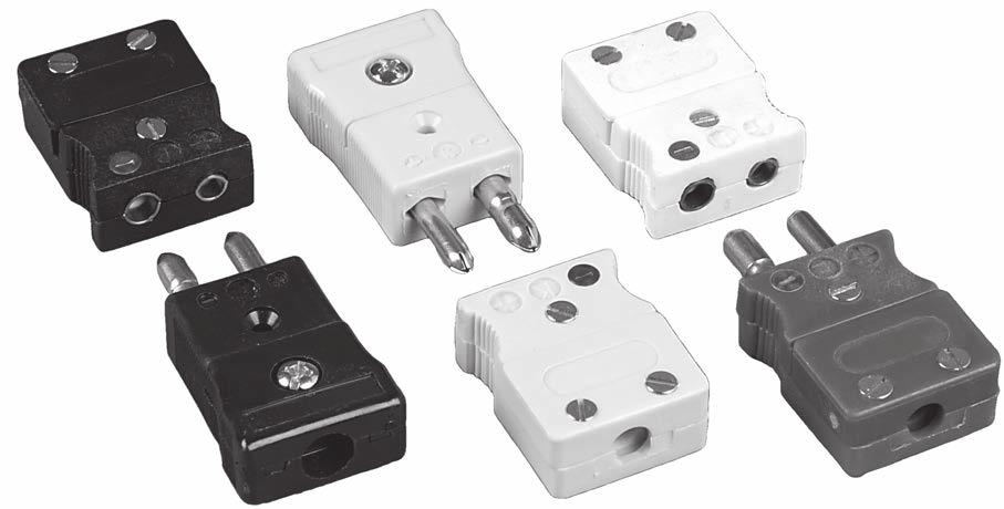

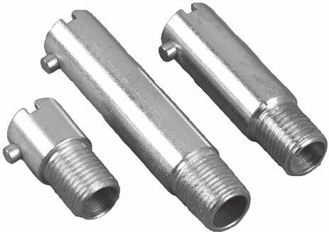

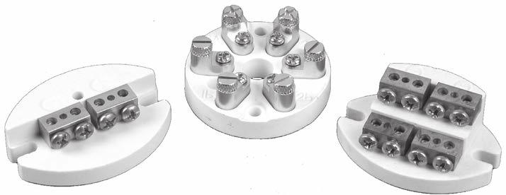


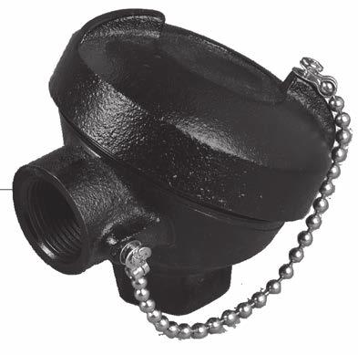

68 Accessories INTRODUCTION All the extras needed to complete your thermal processing installation are available from Durex. A comprehensive line of sensor accessories are stocked and ready for immediate shipping. 68
69 Accessories INSULATED THERMOCOUPLE WIRE TYPE J THERMOCOUPLE WIRE ANSI Color : Positive - White, Negative - Red, Overall - Brown Insulation Insulation Temperature Rating Gauge Part Number Limits of Error Solid / Stranded Flexible PVC Plastic, Duplex Parallel, Ripcord Peelable Construction Extruded Flexible Teflon FEP Plastic, Duplex Parallel, Extruded FEP Jacket Fused TFE Tape, Duplex Parallel, TFE Tape Jacket Polyimide Fused Tape, Duplex Parallel, Polyimide Fused Tape Jacket 221 F (105 C) 400 F (204 C) 500 F (260 C) 600 F (315 C) 24 LJD-24-SL-PVC-RIP Standard Solid 24 LJS-24-SL-PVC-RIP Special Solid 20 LJD-20-SL-FEP-FEP Standard Solid 20 LJS-20-SL-FEP-FEP Special Solid 20 LJD-20-ST-FEP-FEP Standard Stranded 24 LJD-24-SL-FEP-FEP Standard Solid 24 LJS-24-SL-FEP-FEP Special Solid 24 LJD-24-ST-FEP-FEP Standard Stranded 20 LJD-20-SL-TFE-TFE Standard Solid 20 LJS-20-SL-TFE-TFE Special Solid 24 LJD-24-SL-TFE-TFE Standard Solid 24 LJS-24-SL-TFE-TFE Special Solid 20 LJD-20-SL-KAP-KAP Standard Solid 20 LJD-20-ST-KAP-KAP Standard Stranded 20 LJS-20-SL-KAP-KAP Special Solid 24 LJD-24-ST-KAP-KAP Standard Stranded Polyimide Fused Tape, Twisted Pair, No Jacket 600 F (315 C) 24 LJS-24-SL-KAP-TW Special Solid Fiberglass Wrap, Duplex Parallel, Fiberglass Braided Jacket Fiberglass Braid, Duplex Parallel, Fiberglass Braid Jacket Fiberglass Braid, Duplex Parallel, Fiberglass Braid Jacket, Stainless Steel Overbraid High Temperature Glass Braid, Duplex Parallel, High Temperature Glass Braid Jacket 900 F (480 C) 900 F (480 C) 900 F (480 C) 1300 F (705 C) 28 LJD-28-SL-FGW-FBG Standard Solid 28 LJS-28-SL-FGW-FBG Special Solid 30 LJD-30-SL-FGW-FBG Standard Solid 30 LJS-30-SL-FGW-FBG Special Solid 20 LJD-20-SL-FBG-FBG Standard Solid 20 LJS-20-SL-FBG-FBG Special Solid 20 LJD-20-ST-FBG-FBG Standard Stranded 22 LJD-22-ST-FBG-FBG Standard Stranded 24 LJD-24-SL-FBG-FBG Standard Solid 24 LJS-24-SL-FBG-FBG Special Solid 24 LJD-24-ST-FBG-FBG Standard Stranded 20 LJD-20-SL-FBG-SSB Standard Solid 20 LJD-20-ST-FBG-SSB Standard Stranded 22 LJD-22-ST-FBG-SSB Standard Stranded 20 LJD-20-SL-FBH-FBG Standard Solid 20 LJS-20-SL-FBH-FBG Special Solid 69
70 Accessories INSULATED THERMOCOUPLE WIRE TYPE K THERMOCOUPLE WIRE ANSI Color : Positive - Yellow, Negative - Red, Overall - Brown Insulation Flexible PVC Plastic, Duplex Parallel, Ripcord Peelable Construction Extruded Flexible Teflon FEP Plastic, Duplex Parallel, Extruded FEP Jacket Fused TFE Tape, Duplex Parallel, TFE Tape Jacket Polyimide Fused Tape, Duplex Parallel, Polyimide Fused Tape Jacket Insulation Temperature Rating 221 F (105 C) 400 F (204 C) 500 F (260 C) 600 F (315 C) Gauge Part Number Limits of Error Solid / Stranded 24 LKD-24-SL-PVC-RIP Standard Solid 24 LKS-24-SL-PVC-RIP Special Solid 20 LKD-20-SL-FEP-FEP Standard Solid 20 LKS-20-SL-FEP-FEP Special Solid 20 LKD-20-ST-FEP-FEP Standard Stranded 24 LKD-24-SL-FEP-FEP Standard Solid 24 LKS-24-SL-FEP-FEP Special Solid 24 LKD-24-ST-FEP-FEP Standard Stranded 20 LKD-20-SL-TFE-TFE Standard Solid 20 LKS-20-SL-TFE-TFE Special Solid 24 LKD-24-SL-TFE-TFE Standard Solid 24 LKS-24-SL-TFE-TFE Special Solid 20 LKD-20-SL-KAP-KAP Standard Solid 20 LKD-20-ST-KAP-KAP Standard Stranded 20 LKS-20-SL-KAP-KAP Special Solid 24 LKS-24-ST-KAP-KAP Standard Stranded Polyimide Fused Tape, Twisted Pair, No Jacket 600 F (315 C) 24 LKD-24-SL-KAP-TW Standard Solid Fiberglass Wrap, Duplex Parallel, Fiberglass Braided Jacket Fiberglass Braid, Duplex Parallel, Fiberglass Braid Jacket Fiberglass Braid, Duplex Parallel, Fiberglass Braid Jacket, Stainless Steel Overbraid High Temperature Glass Braid, Duplex Parallel, High Temperature Glass Braid Jacket Ceramic Fiber Braid, Twisted Pair, No Jacket (CRH = Heavy Build, CRM = Medium Build) 900 F (480 C) 900 F (480 C) 900 F (480 C) 1300 F (705 C) 2200 F (1205 C) 28 LKD-28-SL-FGW-FBG Standard Solid 28 LKS-28-SL-FGW-FBG Special Solid 30 LKD-30-SL-FGW-FBG Standard Solid 30 LKS-30-SL-FGW-FBG Special Solid 20 LKD-20-SL-FBG-FBG Standard Solid 20 LKS-20-SL-FBG-FBG Special Solid 20 LKD-20-ST-FBG-FBG Standard Stranded 22 LKD-22-ST-FBG-FBG Standard Stranded 24 LKD-24-SL-FBG-FBG Standard Solid 24 LKS-24-SL-FBG-FBG Special Solid 24 LKD-24-ST-FBG-FBG Standard Stranded 20 LKD-20-SL-FBG-SSB Standard Solid 20 LKD-20-ST-FBG-SSB Standard Stranded 22 LKD-22-ST-FBG-SSB Standard Stranded 20 LKD-20-SL-FBH-FBG Standard Solid 20 LKS-20-SL-FBH-FBG Special Solid 20 LKD-20-SL-CRH-CRH Standard Solid 20 LKS-20-SL-CRH-CRH Special Solid 20 LKD-20-SL-CRM-CRM Standard Solid 20 LKS-20-SL-CRM-CRM Special Solid 70
71 Accessories INSULATED THERMOCOUPLE WIRE TYPE T THERMOCOUPLE WIRE ANSI Color : Positive - Blue, Negative - Red, Overall - Brown Insulation Flexible PVC Plastic, Duplex Parallel, Ripcord Peelable Construction Extruded Flexible Teflon FEP Plastic, Duplex Parallel, Extruded FEP Jacket Insulation Temperature Rating 221 F (105 C) 400 F (204 C) Gauge Part Number Limits of Error Solid / Stranded 24 LTD-24-SL-PVC-RIP Standard Solid 24 LTS-24-SL-PVC-RIP Special Solid 20 LTD-20-SL-FEP-FEP Standard Solid 20 LTS-20-SL-FEP-FEP Special Solid 20 LTD-20-ST-FEP-FEP Standard Stranded 24 LTD-24-SL-FEP-FEP Special Solid 30 LTS-30-SL-FEP-FEP Special Solid Flexible FEP Plastic, Twisted Pair with Aluminum Shield and Copper Drain Wire, FEP Jacket 400 F (204 C) 20 LTD-20-SL-FEP-FEPS Standard Solid Fused TFE Tape, Duplex Parallel, TFE Tape Jacket Fiberglass Braid, Duplex Parallel, Fiberglass Braided Jacket 500 F (260 C) 900 F (480 C) 20 LTS-20-SL-TFE-TFE Special Solid 24 LTD-24-SL-TFE-TFE Standard Solid 20 LTD-20-SL-FBG-FBG Standard Solid 24 LTD-24-SL-FBG-FBG Standard Solid TYPE JX THERMOCOUPLE EXTENSION WIRE ANSI Color : Positive - White, Negative - Red, Overall - Brown Insulation Insulation Temperature Range Gauge Part Number Limits of Error Solid / Stranded 16 LJX-16-SL-PVC-PVC Standard Solid Flexible PVC Plastic, Duplex Parallel, PVC Jacket Flexible PVC Plastic, Twisted Pair with Aluminum Shield and Copper Drain Wire, PVC Jacket Flexible PVC Plastic, 4 Twisted Pairs, PVC Jacket with Aluminum Shield and Copper Drain Wire 221 F (105 C) 20 LJX-20-SL-PVC-PVC Standard Solid 20 LJX-20-ST-PVC-PVC Standard Stranded 16 LJX-16-SL-PVC-PVCS Standard Solid 221 F (105 C) 20 LJX-20-SL-PVC-PVCS Standard Solid 20 LJX-20-ST-PVC-PVCS Standard Stranded 221 F (105 C) 20 LJX-20-SL-PVC-PVCS-4PR Standard Solid Flexible PVC Plastic, 8 Twisted Pairs, PVC Jacket with Aluminum Shield and Copper Drain Wire 221 F (105 C) 20 LJX-20-SL-PVC-PVCS-8PR Standard Solid Flexible FEP Plastic, Duplex Parallel, FEP Jacket 400 F (204 C) 20 LJX-20-SL-FEP-FEP Standard Solid Flexible FEP Plastic, Twisted Pair with Aluminum Shield and Copper Drain Wire, FEP Jacket 400 F (204 C) 16 LJX-16-SL-FEP-FEPS Special Solid 20 LJX-20-SL-FEP-FEPS Standard Solid Fiberglass Braid, Duplex Parallel, Fiberglass Braided Jacket 900 F (480 C) 16 LJX-16-SL-FBG-FBG Standard Solid 71
72 Accessories INSULATED THERMOCOUPLE WIRE TYPE KX THERMOCOUPLE EXTENSION WIRE ANSI Color : Positive - Yellow, Negative - Red, Overall - Brown Insulation Flexible PVC Plastic, Duplex Parallel, PVC Jacket Flexible PVC Plastic, Twisted Pair with Aluminum Shield and Copper Drain Wire, PVC Jacket Insulation Temperature Rating 221 F (105 C) 221 F (105 C) Gauge Part Number Limits of Error Solid / Stranded 16 LKX-16-SL-PVC-PVC Standard Solid 20 LKX-20-SL-PVC-PVC Standard Solid 20 LKX-20-ST-PVC-PVC Standard Stranded 16 LKX-16-SL-PVC-PVCS Standard Solid 20 LKX-20-SL-PVC-PVCS Standard Solid 20 LKX-20-ST-PVC-PVCS Standard Stranded Flexible PVC Plastic, 4 Twisted Pairs, PVC Jacket with Aluminum Shield and Copper Drain Wire Flexible PVC Plastic, 8 Twisted Pairs, PVC Jacket with Aluminum Shield and Copper Drain Wire 221 F (105 C) 20 LKX-20-SL-PVC-PVCS-4PR Standard Solid 221 F (105 C) 20 LKX-20-SL-PVC-PVCS-8PR Standard Solid Flexible FEP Plastic, Duplex Parallel, FEP Jacket 400 F (204 C) 20 LKX-20-SL-FEP-FEP Standard Solid Flexible FEP Plastic, Twisted Pair with Aluminum Shield and Copper Drain Wire, FEP Jacket 400 F (204 C) 16 LKX-16-SL-FEP-FEPS Standard Solid 20 LKX-20-SL-FEP-FEPS Standard Solid TYPE TX THERMOCOUPLE EXTENSION WIRE ANSI Color : Positive - Blue, Negative - Red, Overall - Brown Insulation Insulation Temperature Rating Gauge Part Number Limits of Error Solid / Stranded 16 LTX-16-SL-PVC-PVC Standard Solid Flexible PVC Plastic, Duplex Parallel, PVC Jacket Flexible PVC Plastic, Twisted Pair with Aluminum Shield and Copper Drain Wire, PVC Jacket Flexible PVC Plastic, 4 Twisted Pairs, PVC Jacket with Aluminum Shield and Copper Drain Wire 221 F (105 C) 20 LTX-20-SL-PVC-PVC Standard Solid 20 LTX-20-ST-PVC-PVC Standard Stranded 16 LTX-16-SL-PVC-PVCS Standard Solid 221 F (105 C) 20 LTX-20-SL-PVC-PVCS Standard Solid 20 LTX-20-ST-PVC-PVCS Standard Stranded 221 F (105 C) 20 LTX-20-SL-PVC-PVCS-4PR Standard Solid Flexible PVC Plastic, 8 Twisted Pairs, PVC Jacket with Aluminum Shield and Copper Drain Wire 221 F (105 C) 20 LTX-20-SL-PVC-PVCS-8PR Standard Solid Flexible FEP Plastic, Duplex Parallel, FEP Jacket 400 F (204 C) 20 LTX-20-SL-FEP-FEP Standard Solid Flexible FEP Plastic, Twisted Pair with Aluminum Shield and Copper Drain Wire, FEP Jacket 400 F (204 C) 16 LTX-16-SL-FEP-FEPS Standard Solid 20 LTX-20-SL-FEP-FEPS Standard Solid 72
73 Accessories INSULATED THERMOCOUPLE WIRE TYPE TX THERMOCOUPLE EXTENSION WIRE ANSI Color : Positive - Blue, Negative - Red, Overall - Blue Insulation PVC Duplex-Parallel Extruded Jacket PVC Duplex Twisted Shield with Drain Extruded Jacket Extruded Teflon FEP Duplex Twisted Shield with Drain Extruded Jacket Insulation Temperature Rating 221 F (105 C) 221 F (105 C) 400 F (204 C) Gauge Part Number Nominal Size Solid / Stranded 16 TX16-PP0.115 x.190 Solid 20 TX20-PP0.095 x.158 Solid 20 TFX20-PP0.113 x.182 Stranded 16 TX16-PTD0.070 x.120 Stranded 20 TX20-PTD0.045 x.080 Solid 16 TX16-ETD0.075 x.120 Solid 20 TX20-ETD0.080 x.160 Stranded TYPE EX THERMOCOUPLE EXTENSION WIRE ANSI Color : Positive - Purple, Negative - Red, Overall - Purple Insulation Insulation Temperature Rating Gauge Part Number Nominal Size Solid / Stranded PVC Duplex-Parallel Extruded Jacket 221 F (105 C) 20 EX20-PP0.095 X.158 Solid PVC Duplex-Twisted Extruded Jacket 221 F (105 C) 20 EXF20-PT0.180 Stranded PVC Duplex Twisted Shield with Drain Extruded Jacket 221 F (105 C) 16 EX16-PTD0.220 Solid 20 EX20-PTD0.184 Solid TYPE NX THERMOCOUPLE EXTENSION WIRE ANSI Color : Positive - Orange, Negative - Red, Overall - Orange Insulation Insulation Temperature Rating Gauge Part Number Nominal Size Solid / Stranded PVC Duplex-Parallel Extruded Jacket 221 F (105 C) 20 NX20-PP0.095 x.158 Solid 73
74 Accessories INSULATED THERMOCOUPLE WIRE TYPE RX or SX THERMOCOUPLE EXTENSION WIRE ANSI Color : Positive - Black, Negative - Red, Overall - Green Insulation PVC Duplex-Parallel Extruded Jacket Glass Braid Duplex-Parallel Braided Jacket SS Protective Overbraid Extruded Teflon FEP Duplex-Parallel Extruded Jacket Insulation Temperature Rating 221 F ( 105 C) 221 F ( 105 C) 400 F (105 C) Gauge Part Number Nominal Size Solid / Stranded 16 R,SX16-PP0.115 x.190 Solid 20 R,SX20-PP0.095 x.158 Solid 16 R,SX16-PTD0.220 Solid 20 R,SX20-PTD0.184 Solid 16 R,SX16-ET0.085 x.155 Solid 20 R,SX20-ET0.065 x.110 Solid Teflon TFE Fused Tape Duplex-Parallel Fused Tape Jacket *500 F (260 C) 16 R,SX16-TT0.085 x.155 Solid Extruded Teflon FEP Duplex Twisted Shield with Drain Extruded Jacket Glass Braid Duplex-Parallel Braided Jacket 400 F (105 C) *900 F (482 C) 16 R,SX16-ETD0.220 Solid 20 R,SX20-ETD0.131 Solid 16 R,SX16-GG0.110 x.160 Solid 20 R,SX20-GG0.060 x.100 Solid 24 R,SX24-GG0.045 x.080 Solid *Extension wire limit is 400 F (204 C) TYPE BX THERMOCOUPLE EXTENSION WIRE (Alloy PCLW630 vs. Copper) ANSI Color : Positive - Gray, Negative - Red, Overall - Gray Insulation Insulation Temperature Rating Gauge Part Number Nominal Size Solid / Stranded Glass Braid Duplex-Parallel Braided Jacket *900 F (482 C) 20 BX20-GG0.060 x.100 Solid *Extension wire limit is 400 F (204 C) TYPE CX THERMOCOUPLE EXTENSION WIRE (Alloy 405 vs. Alloy 426) ANSI Color : Positive - Orange, Negative - Red, Overall - Orange/Black Insulation Insulation Temperature Rating Gauge Part Number Nominal Size Solid / Stranded Glass Braid Duplex-Parallel Braided Jacket *900 F (482 C) 20 CX20-GG0.050 x.090 Solid *Extension wire limit is 400 F (204 C) 74
75 Accessories THERMOCOUPLE CONNECTIONS 1 ½ 1 ¼ ⅞ Fits Standard æ Knockout Plug Jack Circular Panel Jack Calibration Color Plug Number Jack Number Circular Jack J Black K Yellow T Blue E Purple R/S Green CU White Note: Standard temperature rating is 400 F. High temperature available at 550 F. Mini Plug Mini Jack Mini Circular Panel Jack Calibration Color Plug Number Jack Number Circular Jack J Black K Yellow T Blue E Purple R/S Green CU White Note: Standard temperature rating is 400 F. High temperature available at 550 F. PANEL JACK STRIPS ¾ ⁷/₁₆ 1 ¾ A Length ¹³/₁₆ C Length Panel Mounting Cutout s 1 ¼ Panel Length Number of Circuits Cutout Dim. C 1 ½ 2 1 ⁵/₁₆ 2 ¼ 3 2 ¹/₁₆ ¹³/₁₆ 3 ¼ 5 3 ⁹/₁₆ 4 ½ 6 4 ⁵/₁₆ 5 ¼ 7 5 ¹/₁₆ ¹³/₁₆ 6 ¾ 9 6 ⁹/₁₆ 7 ½ 10 7 ⁵/₁₆ 8 ¼ 11 8 ¹/₁₆ ¹³/₁₆ Part Number Sequence PS K 9 PS Design E, J, K, or T Calibration Table Above Number of Circuits 75
76 Accessories THERMOCOUPLE ACCESSORIES Cable Clamp Part # Overbraid or Armor Cable Stainless Steel Armor Cable Part # Size ⅛ ID x.210 OD ⁵/₃₂ ID x.234 OD ³/₁₆ ID x ⁹/₃₂ OD ¼ ID x ¹¹/₃₂ OD ⅜ ID x ½ OD ½ ID x ⅝ OD TERMINAL BLOCKS SB100 Single Block DB100 Duplex Block TB100 Triplex Block TERMINAL HEADS 3 ⅛ 3 ³/₁₆ 3 ⅛ 1 ¾ 2 ¹⁵/₁₆ 2 ⅛ 1 ½ Part # Cast Iron Terminal Head Process Connection x Conduit Connection ½ NPT x ¾ NPT ¾ NPT x ¾ NPT NPT x ¾ NPT Cast Aluminum Terminal Head Part # Process Connection x Conduit Connection ½ NPT x ¾ NPT ¾ NPT x ¾ NPT NPT x ¾ NPT Miniature Plastic Terminal Head Part # Process Connection x Conduit Connection ¼ NPT x ¼ NPT ⅜ NPT x ¼ NPT 76
77 Accessories COMPRESSION FITTINGS Compression fittings allow for the exact immersion depth to be set on the thermocouple during field installation. When ordered as part of a thermocouple assembly, the fittings will be assembled finger-tight to the sheath. The compression fittings are rated up to 10,000 psi dependent upon the sheath diameter, thread size, material and temperature requirement. 316 SS* Brass* Sheath Diameter Male NPT Finger-tight Length Threaded Length ¹/₁₆ ¹/₁₆ ¹⁵/₁₆ ⅜ ¹/₁₆ ⅛ ⁶³/₆₄ ⅜ ⅛ ⅛ 1 ¹¹/₆₄ ⅜ ⅛ ¼ 1 ⅜ ⁹/₁₆ ³/₁₆ ⅛ 1 ⁷/₃₂ ⅜ ³/₁₆ ¼ 1 ²⁷/₃₂ ⁹/₁₆ ¼ ¼ 1 ³¹/₆₄ ⁹/₁₆ ⁵/₁₆ ¼ 1 ³³/₆₄ ⁹/₁₆ ⅜ ¼ 1 ³⁷/₆₄ ⁹/₁₆ ⅜ ½ 1 ⁵¹/₆₄ ¾ *Additional materials: Steel, Aluminum, Monel, Nylon, TPE Adjustable compression fittings are available upon request with 500 F (260 C) Teflon sealant. BLANK BOLTS L 3, 6 Standard ½ - 20 UNF-2A Thread 2 ³/₁₆.500 Dia. ½ Part Number L Blank bolt occupies hole when melt bolt is removed. BAYONET ADAPTER ⁷/₁₆ A Length Bayonet Number A Length Thread Size ⅞ ⅛ - 27 NPT ⅛ ⅛ - 27 NPT ½ ⅛ - 27 NPT ⅛ - 27 NPT ½ ⅛ - 27 NPT ¼ ⅛ - 27 NPT ⅞ ⅜ - 24 NF ½ ⅜ - 24 NF TERMINAL BARRIER STRIPS Note: Add Design Number and CODE to number of screws for part number. Ex: TRMS-J-4 Terminal Jumper (Positive) (CH) Chromel (IR) Iron Terminal Jumper (Negative) (AL) Alumel (CO) Constantan s Limits of Error E J K T Standard Limits Special Limits # of screws

78 Accessories 2-WIRE PROGRAMMABLE TRANSMITTERS 5331D Features: RTD,, Ohm, or mv input Extremely high measurement accuracy 1.5 kvac galvanic isolation Programmable sensor error value For DIN form B sensor head mounting 5333D Features: RTD or Ohm input High measurement accuracy 3-wire connection Programmable sensor error value For DIN form B sensor head mounting 5334B Features: input High measurement accuracy Galvanic isolation Programmable sensor error value For DIN form B sensor head mounting Typical Applications: Linearised temperature measurement with Pt100 - Pt1000, Ni100 - Ni1000, or thermocouple sensor. Conversion of linear resistance variation to a standard analogue current signal, for instance from valves or Ohmic level sensors. Amplification of a bipolar mv signal to a standard 4-20 ma current signal. Technical Characteristics: Within a few seconds the user can program the transmitter to measure temperatures within all ranges defined by the norms. The RTD and resistance inputs have cable compensation for 2-, 3-, and 4-wire connection. Continuous check of vital stored data for safety reasons. Cold junction compensation (CJC) with a built-in temperature sensor. (Transmitter 5334B) Mounting and Installation: For DIN form B sensor head mounting NB: As Ex barrier we recommend 5104B, 5114B, or 5116B 78
MGO INSULATED THERMOCOUPLES INDEX
 MGO INSULATED THERMOCOUPLES INDEX PAGE General Information... M1 Part Numbering Examples... M4 Thermocouple Elements (MA)... M5 Leadwire Style Thermocouples (MB)... M6 Leadwire Style Thermocouples (MD,
Thermal Solutions Worldwide SECTION C. Industrial Thermocouples and RTDs. Straight Thermocouples Assemblies with Metal Protection Tubes C-5
 Thermal Solutions Worldwide SECTION C Industrial Thermocouples and RTDs Straight Base Metal Thermocouple Elements C1 Angle Base Metal Thermocouple Elements C2 Straight Noble Metal Thermocouple Elements
THERMOWELL ASSEMBLIES & THERMOWELLS INDEX
 THERMOWELL ASSEMBLIES & THERMOWELLS INDEX PAGE General Information & Part Numbering Examples... T2 RTD & T/C Style Thermowell Assemblies RTD'S for Thermowells (RT, RV, R4, RW, R1, R2, R5, or R8)... T3
Resistance Temperature Detectors (RTD)
") Resistance Temperature Detectors (RTD) Style H Connection Head Assembly Connection Head Option A - Aluminum Tip Style F - Flat Tip Head Fitting Option G - ½ NPT Hex Nipple Head Fitting Option A - Fixed
Resistance Temperature Detectors (RTD) Style H Connection Head Assembly Connection Head Option A - Aluminum Tip Style F - Flat Tip Head Fitting Option G - ½ NPT Hex Nipple Head Fitting Option A - Fixed
INDUSTRIAL TEMPERATURE SENSORS
 Temperature s INDUSTRIAL TEMPERATURE SENSORS Temperature s APPLIED SENSOR TECHNOLOGIES A DIVISION OF UNITED ELECTRIC CONTROLS T E M P S E N S O R - B - 0 2 Temperature s Temperature s index Subject Page
AccuTru Sensor Technologies
 High Temperature ExL Ceramic Sheathed Thermocouples NEW TECHNOLOGIES (exclusively from AccuTru) Mi-Dry, ExL, SVS AccuTru is becoming well known in the process control community as a leading edge sensor
Thermocouples W A T L O W
 W A T L O W General Applications Over 90 years of manufacturing, research and design makes Watlow a world class supplier of temperature measurement products. We have designed and manufactured millions
Sheathed Thermocouple Sensor (120 Series)
") Applications 120 series comprise a thin-walled and felxible mineral insulated sheath cable made of stainless steel or inconel. The cable contains thermal wires embed in pressed fireproof manesium oxide.
Applications 120 series comprise a thin-walled and felxible mineral insulated sheath cable made of stainless steel or inconel. The cable contains thermal wires embed in pressed fireproof manesium oxide.
RTDs. Offered by. Phone: (203) Fax: (203) Specialists in Valves, Controls, Pneumatics, Fluid Measurement
 Fax: (203) Specialists in Valves, Controls, Pneumatics, Fluid Measurement") RTDs Offered by Phone: (203) 261-6711 Fax: (203) 261-8331 www.okcautomation.com Specialists in Valves, Controls, Pneumatics, Fluid Measurement NS RTD s I- Theory of Operation n RTD s basis of operation
RTDs Offered by Phone: (203) 261-6711 Fax: (203) 261-8331 www.okcautomation.com Specialists in Valves, Controls, Pneumatics, Fluid Measurement NS RTD s I- Theory of Operation n RTD s basis of operation
Section 2 Index PAGE 2-I. Metal Sheath and Ceramic Thermocouple Assemblies. AccuTru Sensor Technologies 2-1. Spring Loaded Hex Nipple w/ Head 2-2
 Section 2 Index Model Metal Sheath and Ceramic Thermocouple Assemblies Page I1 GTAW Welded Hex Nipple w/ Head 2-1 I2 Spring Loaded Hex Nipple w/ Head 2-2 I3 Spring Loaded Pipe Nipple w/ Head 2-3 I4 Nipple-Union-Nipple
Resistance Temperature Detectors
 PRODUCT REFERENCE GUIDE Probes & Assemblies PRODUCT FEATURES Rugged Construction Accurate and Stable Probes General Purpose, Tip Sensitive, High Temperature and High Vibration Probes and Assemblies 2,
AccuTru ExL High Temperature Thermocouples
 S E N S O R T E C H N O L O G I E S AccuTru ExL High Temperature Thermocouples Dedicated to those organizations that value improved temperature measurement for critical processes S E N S O R T E C H N
Thermocouples and Accessories Product Catalog
 Thermocouples and Accessories Product Catalog 7282 N. Haggerty Rd. Canton, MI 48187 P. 734-451-8740 / F. 734-451-8741 www.inspec-inc.com 1 P a g e EXPERT CONTROL AND INSTRUMENTATION REPAIR Plastics Industry
General Purpose Thermocouples
 General Purpose Thermocouples Style GP Rigid Tube Assembly T G P 1 2 3 4 5 6 7 8 9 10 11 12 13 14 15 16 1. Calibration (See page 13 for other Cals) J = Type J (1400 o F) T = Type T (700 o F) K = Type K
Mineral Insulated (MgO) Thermocouples
 Thermocouples") Mineral Insulated (MgO) Thermocouples Style F Transition Assembly E (4 std) T F 1 2 3 4 5 6 7 8 9 10 11 12 13 14 15 16 17 1. Transition (See page 18 for more transitions) A = Standard Transition w/relief
Mineral Insulated (MgO) Thermocouples Style F Transition Assembly E (4 std) T F 1 2 3 4 5 6 7 8 9 10 11 12 13 14 15 16 17 1. Transition (See page 18 for more transitions) A = Standard Transition w/relief
Infinite Thermal Solutions Inc. Thermocouples and RTDs
 Thermocouples and RTDs Page 120 T121 R121 T221 R221 T122 R122 T12 R12 T22 R22 T222 R222 ORDERING INFORMATION - 1 2 4 5 6 7 8 9 10 11 12 1 14 15 16 Type T = Thermocouple 04 Stainless Steel Protection Tube
General Purpose Thermocouples
 General Purpose Thermocouples Style IW Insulated Wire Assembly A Leadwire Construction Option A - Solid Fiberglass Termination Option T - Split Leads A Special Option T - Acid Resistant Teflon Sealed Tip
Mineral Insulated (MgO) Thermocouples
 Thermocouples") Option F - Flat Tip Head Fitting Option G - ½ NPT Hex Nipple Connection Head Option A - Aluminum Mineral Insulated (MgO) Thermocouples Option F - Flat Tip Head Fitting Option G - ½ NPT Hex Nipple Style
Option F - Flat Tip Head Fitting Option G - ½ NPT Hex Nipple Connection Head Option A - Aluminum Mineral Insulated (MgO) Thermocouples Option F - Flat Tip Head Fitting Option G - ½ NPT Hex Nipple Style
Resistance Temperature Detectors
 Resistance Temperature etectors INTROUTION For high-accuracy temperature measurements in a variety of industrial and commercial air and gas applications, urex Industries offers RT s of multiple elements
Thermal-Tab and Thermal-Ribbon Sensors
 Thermal-Tab and Thermal-Ribbon Sensors Install these compact sensors anywhere for accurate point sensing and fast response. All Thermal-Tab modules use a thin-film RTD element. All Thermal-Ribbon models
THERMOCOUPLE TECHNICAL REFERENCE DATA
 THERMOCOUPLE TECHNICAL REFERENCE DATA Thermocouples are temperature sensors suitable for use with any make of instrument designed or programmed for use with the same type of thermocouple. Thermocouples
Automotive air or oil temperature Appliances cooking temperature. MOUNTING DIMENSIONS (for reference only)
") TD Series FEATURES Interchangeable without sensor-tosensor recalibration Very small thermal mass for fast response Air or liquid temperature sensing Linear temperature sensitivity Proven thin film processing
TD Series FEATURES Interchangeable without sensor-tosensor recalibration Very small thermal mass for fast response Air or liquid temperature sensing Linear temperature sensitivity Proven thin film processing
Industrial Thermocouples
 Industrial Thermocouples Industrial thermocouples are used in high temperature applications, such as those listed below. Several calibrations are available as well as various mechanical configurations.
T/C, Noble, Straight Ceramic
 Introduction T/C, Noble, Straight Ceramic Thermocouple, Noble Metal Ceramic Tube, Straight Applications Ordering Information Elements are constructed of high quality material using modern techniques to
E (4 std) (1/4 std) 1. Calibration (See page 13 for other Cals) 3. Junction Grounded Ungrounded
 (1/4 std) 1. Calibration (See page 13 for other Cals) 3. Junction Grounded Ungrounded") Special Purpose Style LN Adjustable Lockcap Assembly Style S Fixed Bayonet Thermocouple Assembly Style LN Lockcap Armor Assembly Bend Option G - Straight A (4 std) Leadwire Construction Option O - Stranded
Special Purpose Style LN Adjustable Lockcap Assembly Style S Fixed Bayonet Thermocouple Assembly Style LN Lockcap Armor Assembly Bend Option G - Straight A (4 std) Leadwire Construction Option O - Stranded
Industrial Process Thermocouples
 s ASE ETAL PROTECTION TUE ASSELY The TPT Style assemblies feature a base metal thermocouple and metal protection tube for use in corrosive or hostile environments. Optional mounting bushings and flanges
SECTION 2: PROBES. Page 2-1
 SECTION 2: PROBES RTDs and thermocouples in a variety of configurations for easy installation Tip-sensitive and fast response probes for quick and accurate temperature sensing High temperature probes to
Metal Transitions HIGH TEMPERATURE
 Metal Transitions High Temperature Thermal Solutions of Texas continues to meet the demands of technological advances by developing thermocouples using materials with unusually high performance characteristics
Mineral Insulated Platinum Resistance Thermometer PT100 Sensor - Available in 3mm or 6mm diameter x 150mm or 250mm probe lengths
 Datasheet ENGLISH Mineral Insulated Platinum Resistance Thermometer PT100 Sensor - Available in 3mm or 6mm diameter x 150mm or 250mm probe lengths High temperature, rugged, flexible Pt100 probe Suitable
THERMOCOUPLE TECHNICAL REFERENCE DATA
 THERMOCOUPLE TECHNICAL REFERENCE DATA Thermocouples are temperature sensors suitable for use with any make of instrument designed or programmed for use with the same type of thermocouple. Thermocouples
A thermocouple assembly generally has four major components:
 Introduction Several methods of temperature measurement and control have been developed over the years. Industrial process control usually requires that the temperature sensing device must be remote from
S E C T I O N 3 : P R O B E S
 S E C T I O N 3 : P R O B E S RTDs and thermocouples in a variety of configurations for easy installation Tip-sensitive and fast response probes for quick and accurate temperature sensing High temperature
Thermocouple temperature sensor omnigrad T -TSC 310
 Technical information TI 255T/02/en 60019734 Thermocouple temperature sensor omnigrad T -TSC 310 Probe in direct contact with the process Insulation in mineral oxide Extension cable in glass fibre TSC
4 RESISTANCE THERMOMETRY
 4.1 4 RESISTANCE THERMOMETRY PRINCIPLES AND APPLICATIONS OF RESISTANCE THERMOMETERS AND THERMISTOR Resistance thermometers and Thermistor are temperature sensors, which changes there electrical resistance
150 mm. 1/8 BSPP brass male compression fitting with locknut included
 ENGLISH Datasheet Platinum Resistance PT100 Flat Tip Probe 4mm diameter x 150mm long 2 wire with 1 metre flying lead, complete with 1/8 BSP compression fitting & locknut 4mm 25mm 5.5/6mm(max) 150 mm General
Overview. A thermocouple assembly generally has four major components:
 Introduction Several methods of temperature measurement and control have been developed over the years. Industrial process control usually requires that the temperature sensing device must be remote from
ENGLISH. Datasheet. RS single element: Single 4 wire element, allowing connection to any Pt100 2, 3 or 4 wire instrument
 Datasheet ENGLISH Platinum Resistance Thermometer Pt100 Outdoor/Cold Store Temperature Sensors IP67 Weatherproof Housing, 4 wire single or dual element, or 4-20mA option Weatherproof IP67 rated wall mounting
Available J, K, T, E, R, S, J, K, T, E J, K, T, E J, K, T, E J, K, T, E J, K, T, E, N
 Thermocouple Series No. Unsheathed T/C 5TC/5SRTC 5SC SA1 CO1 Bare, SH, DH, FS Page No. A-15 A-19 A-23 A-25 A-26 A-28 Price $17 pkg of 5 $33 pkg of 5 $58 pkg of 5 $60 pkg of 5 $17 $6 Configuration Fine
Resistance Temperature Detectors (RTDs)
") Website: Resistance Temperature Detectors (RTDs) Resistance Temperature Detectors (RTD's). These detectors are frequently used in the plastics industries and many others. Care must be taken to eliminate
Website: Resistance Temperature Detectors (RTDs) Resistance Temperature Detectors (RTD's). These detectors are frequently used in the plastics industries and many others. Care must be taken to eliminate
THERMOMETERS. STANDARD BIMETAL 90 back angle type available in 2, 3 and 5 dials
 THERMOMETERS Thermometers are used to measure temperature. PIC stocks a variety of temperature measuring instruments, including bimetals, magnetic thermometers, tridicators and scale thermometers. STANDARD
SANDELIUS INSTRUMENTS, INC.
 SNDEIUS INSTRUMENTS, INC. To order any style on this page see below: Sandelius Style H Nipple-Union-Nipple (For spring-loading, insert an S in front of the style number) MET SHETHED OR INSUTOR TYPE EEMENT
Platinum Resistance Pt100 Autoclave Drain Probe, 4 Wire Compatible with most common makes of Autoclaves
 ENGLISH Datasheet Platinum Resistance Pt100 Autoclave Drain Probe, 4 Wire Compatible with most common makes of Autoclaves Pt100 Autoclave & steriliser drain temperature probe For use to monitor the fluid
Ceramic Ceramic No. of Lead/Wire Lead Allied RS order Dia Ø Length Wires Type Length Code code
 Datasheet Platinum Resistance Pt100 Tubular Ceramic Insert Elements with tail wires 2 or 4 wire with choice of Teflon or nickel/glassfibre insulated tail wires up to 450mm long ENGLISH 237-1635 237-1641
General Information, Industrial Thermocouple Section
 INDUSTRIAL THERMOCOUPLES INDEX PAGE General Information... I1 Straight Base Metal Thermocouple Elements (IA)... I2 Angled Base Metal Thermocouple Elements (IB)... I3 Noble Metal Thermocouple Elements (IC,
Platinum Resistance Thermometer Pt100 Precision Probe - High accuracy platinum resistance thermometer probe, 6mm diameter x 250mm
 Datasheet ENGLISH Platinum Resistance Thermometer Pt100 Precision Probe - High accuracy platinum resistance thermometer probe, 6mm diameter x 250mm Precision Pt100 sensor offering high accuracy over the
Cable Selection Guide
 Cable Selection Guide au.rs-online.com (Australia) www.rs-components.com (International) Thermocouple Thermometry - At A Glance 60584-1 : 2013 / BS EN 60584-1 : 2013 1 for t < 1100 C, [1 + 0,003 x (t -
ENGLISH Datasheet Platinum Resistance Pt100 4 wire class B Resistance Thermometer with DIN B Head
 ENGLISH Datasheet Platinum Resistance Pt100 4 wire class B Resistance Thermometer with DIN B Head With stainless steel plug (no thread) Pt100 probe with DIN B terminal head Class B, 4 wire connection Various
Proven Capabilities. Features and Benefits. Watlow provides:
 Proven Capabilities Since 1914, SERV-RITE thermocouple wire and thermocouple extension wire from Watlow have been known for premimum performance and reliability. All SERV-RITE wire is manufactured under
Pt100 (100 0 C) to IEC 751, Class B, 4 wire 3.0, 4.0, 4.5 or 6.0mm diameter 316 stainless steel sheath.
 to IEC 751, Class B, 4 wire 3.0, 4.0, 4.5 or 6.0mm diameter 316 stainless steel sheath.") Datasheet Platinum Resistance Thermometer Pt100 Industrial Sensor Probe, Class B Available in 3.0, 4.0, 4.5 or 6.0mm diameter x Various probe lengths ENGLISH Multipurpose Pt100 Probe to IEC751 Class B,
Datasheet Platinum Resistance Thermometer Pt100 Industrial Sensor Probe, Class B Available in 3.0, 4.0, 4.5 or 6.0mm diameter x Various probe lengths ENGLISH Multipurpose Pt100 Probe to IEC751 Class B,
Datasheet Platinum Resistance Pt100 Dual Element Industrial Sensor Probe 6mm diameter x 150mm or 250mm probe lengths
 Datasheet Platinum Resistance Pt100 Dual Element Industrial Sensor Probe 6mm diameter x 150mm or 250mm probe lengths ENGLISH Duplex PRT s with two independent PT100 detectors inside tip of probe. This
Troubleshooting RTDs and Thermocouples
 Troubleshooting RTDs and Thermocouples If you are experiencing audio problems please call the teleconference number below 650-479-3208 Access Code: 663 601 880 Your Host and Presenter 2 Presenter Bill
ISO 9001:2008 certified
 c ISO 9001:2008 certified 3/14 www.setexproducts.com INTRODUCTION SETE Thermowells serve two primary functions: (1) extend temperature instrument life by protecting sensing elements from harsh process
ENGLISH. 1metre 7/.02mm Teflon insulated twin twisted lead
 Datasheet Platinum Resistance Pt100 Sheathed Thin Film Strip Sensor 2 wire sensor sheathed in a thin stainless steel shim body ideal for surface measurement ENGLISH Sheathed Pt100 element in a thin, flat
UTECO. Temperature Probes Overview. Temperature Probes for all Industries Level Switches Accessories, Cables & Transmitters
 UTECO Temperature Probes Overview Temperature Probes for all Industries Level Switches Accessories, Cables & Transmitters About us UTECO S.A has 45 years experience in designing and manufacturing of a
ENGLISH Datasheet Platinum Resistance Pt100 Hygienic Thermometer, 1.5'' RJT style fitting
 ENGLISH Datasheet Platinum Resistance Pt100 Hygienic Thermometer, 1.5'' RJT style fitting RJT unions (Ring Joint Type) are often referred to as a standard union. The compromise of an O-ring style gasket
ENGLISH Datasheet Platinum Resistance Pt1000 Class B Sensor with Teflon insulated lead
 ENGLISH Datasheet Platinum Resistance Pt1000 Class B Sensor with Teflon insulated lead (Image shows 4 wire) Pt1000 element to IEC 751 Class B 2 wire configuration Temperature range -50 C to + 200 C Pt1000
RTD ASSEMBLIES n COMPONENTS AND DESCRIPTIONS. Notes: Sensor Element. Densely Compacted Magnesium Oxide. Ceramic Core. Notes:
 RTD ASSEMBLIES n OMPONENTS AND DESRIPTIONS onax wirewound platinum RTD assemblies feature a wirewound element encased in either a stainless steel or Inconel 00 sheath. The RTD s nickel leadwires are supported
Proven Capabilities. Features and Benefits. Watlow provides:
 Proven Capabilities Since 1914, SERV-RITE thermocouple wire and thermocouple extension wire from Watlow have been known for premium performance and reliability. All SERV-RITE wire is manufactured under
SPRING LOADED THERMOCOUPLE CONFIGURATIONS THERMOWELL & REPLACEABLE INSERT II 2G/D Ex e TCRE/WE
 SPRING LOADED THERMOCOUPLE CONFIGURATIONS THERMOWELL & REPLACEABLE INSERT II 2G/D Ex e TCRE/WE C20 C21 C26-2 C26-2 1 FEATURES TECHNICAL SPECIFICATION ASSEMBLY The industrial spring loaded configuration
SURFACE TEMPERATURE SENSORS
 SURFACE TEMPERATURE SENSORS These sensors are thermocouples and resistance thermometers for surface temperature measurement of objects. C400 R400 Magnet sensors measurement and monitoring of objects such
THERMOCOUPLES & RTDS
 Since 96 S & RTDS W. H. COOKE & CO., INC. 6868 York Road P. O. ox 89 Hanover, P 7 Information (77) 60- Orders (800) 77-55 Fax (77) 67-9999 Email: sales@whcooke.com Web: www.whcooke.com www.whcooke.com
Platinum Resistance Pt100 & Pt1000 Silicone Patch Sensors Element Encapsulated in A Silicone Rubber Patch with Self-Adhesive Aluminium Foil Backing
 Datasheet ENGLISH Platinum Resistance Pt100 & Pt1000 Silicone Patch Sensors Element Encapsulated in A Silicone Rubber Patch with Self-Adhesive Aluminium Foil Backing Pt100 Patch Sensor (100 Ω Ohms @ 0
Will accommodate up to 35 conductors while maintaining separation required to withstand instrumentation voltages
 H.0 ACCESSORIES Introduction Technical Reference Accessories Pressure Viewport Isolator Thermocouple Coaxial Multipin Connector Feedthrough Description Accessories is the product classification given by
THERMOCOUPLES and THERMORESISTANCES - Temperature measurement sensors for industrial use Figure 1: Standard Thermocouples
 THERMOCOUPLES and THERMORESISTANCES - Temperature measurement sensors for industrial use Figure 1: Standard Thermocouples Figure 2: Mineral Oxide Thermocouples Figure 3: Thermoresistances GENERAL CHARACTERISTICS
OPERATING MAINTENANCE INSTRUCTIONS
 System OPERATING MAINTENANCE INSTRUCTIONS Thermocouples are the most widely used temperature sensors. They are low cost, interchangeable, robust and can measure a wide range of temperatures. Thermocouples
Specifications: Ice point resistance: Fundamental interval (0 C to 100 C): 38.5Ω (nominal)
: 38.5Ω (nominal)") ENGLISH Datasheet Platinum Resistance Pt100 Wire-Wound Detector Elements Pt100 platinum resistance thermometer elements in a choice of sizes single & dual element Pt100 elements to IEC 60751 Class A or
ENGLISH Datasheet Platinum Resistance Pt100 Wire-Wound Detector Elements Pt100 platinum resistance thermometer elements in a choice of sizes single & dual element Pt100 elements to IEC 60751 Class A or
INSULATED ELEMENT TWIST WELD DUPLEX INSULATED TIG WELD 1 1/2 NOMINAL ORDER CODES. INSULATOR DIMENSIONS (inches) SINGLE DUPLEX
 SINGLE DUPLEX") Straight Base Metal Thermocouple Elements The straight base metal thermocouple elements illustrated on this catalog page are replacement elements for use in Pyromation's complete industrial thermocouple
Straight Base Metal Thermocouple Elements The straight base metal thermocouple elements illustrated on this catalog page are replacement elements for use in Pyromation's complete industrial thermocouple
NANMAC. Quality Performance Solutions
 NANMAC Quality Performance Solutions This presentation will consist of six sections: Nanmac history and Corporate overview General thermocouple & RTD theory High Temperature Thermocouples Ultra High Temperature
PFA (Fluororesin) coated temperature sensors
 coated temperature sensors") PFA (Fluororesin) coated sensors FT-100 () FR-100 (Resistance Temperature Detecr) Temperature sensor with perfluoroalkoxy polymer resin coating (PFA) excels in chemical and moisture resistance. Measuring
PFA (Fluororesin) coated sensors FT-100 () FR-100 (Resistance Temperature Detecr) Temperature sensor with perfluoroalkoxy polymer resin coating (PFA) excels in chemical and moisture resistance. Measuring
Thermocouple Quick Reference Guide. Aluminium Temperature Sensing Solutions from the Smelter to the Foundry
 Thermocouple Quick Reference Guide Aluminium Temperature Sensing Solutions from the Smelter to the Foundry why pyrotek? Pyrotek is a global engineering leader and innovator of technical solutions, integrated
Will accommodate up to 35 conductors while maintaining separation required to withstand instrumentation voltages
 H.0 Accessories Introduction Description Accessories is the product classification given by CeramTec for miscellaneous hardware that is used to connect, terminate, install, or isolate Ceramaseal products.
Temperature sensors for automotive applications
 Temperature sensors for automotive applications When the precise measurement of temperature is a critical aspect to the safety of a process, the importance of precision quality thermocouple material is
ENGLISH Datasheet Platinum Resistance Pt100 & Pt1000 Thin Film Detectors Platinum Sensing Resistors Thin Film (Pt100 & Pt1000 Ohm)
") ENGLISH Datasheet Platinum Resistance Pt100 & Pt1000 Thin Film Detectors Platinum Sensing Resistors Thin Film (Pt100 & Pt1000 Ohm) Pt100 Elements, Thin Film (100 Ohm) Pt100 elements to IEC751 Class A,
ENGLISH Datasheet Platinum Resistance Pt100 & Pt1000 Thin Film Detectors Platinum Sensing Resistors Thin Film (Pt100 & Pt1000 Ohm) Pt100 Elements, Thin Film (100 Ohm) Pt100 elements to IEC751 Class A,
SPRING LOADED THERMOCOUPLE CONFIGURATIONS
 SPRING LOADED THERMOCOUPLE CONFIGURATIONS FOR USE WITH THERMOWELLS II 3G Ex na/nl TCRN/WN/TN S30 S31 S36-1 S36-2 1 FEATURES TECHNICAL SPECIFICATION ASSEMBLY The industrial spring loaded configuration guarantees
Nickel Temperature Sensors 1/15
 Nickel Temperature Sensors 1/15 General Information In many industrial sectors and fields of research, temperature measurement is one of the most important parameters to determine product quality, security,
SANDELIUS INSTRUMENTS, INC.
 SNDEIUS INSTRUMENTS, INC. To order any style on this page see below: Sandelius Style H Nipple-Union-Nipple (For spring-loading, insert an S in front of the style number) MET SHETHED OR INSUTOR TYPE EEMENT
Resistance Temperature Detectors Mineral Insulated Thermocouples Thermoelements, Accessories and Service All-round supplier
 Resistance Temperature Detectors Mineral Insulated Thermocouples Thermoelements, Accessories and Service All-round supplier of temperature sensors and component parts for all industrial applications Manufactured
Thermocouple for Flue Gas Temperature Measurements,
 Electrical Temperature Measurement Thermocouples for Flue Gas Temperature Measurements Model TC81 with Thermowell Model TW81 WIKA Data Sheet TE 65.81 Applications Blast furnaces, air heaters Red-heat and
Nickel Temperature Sensors 1/12
 Nickel Temperature Sensors 1/12 General Information In many industrial sectors and fields of research, temperature measurement is one of the most important parameters which determines product quality,
Thermocouple Reference Table
 Thermocouple is the description for electrical feedthroughs that are commonly used for temperature measurement systems. A thermocouple feedthrough does not measure temperature, but rather it is used to
GENERAL INFORMATION ABOUT RESISTANCE THERMOMETERS
 Page 1 of 6 GENERAL INFORMATION ABOUT RESISTANCE THERMOMETERS WORKING PRINCIPLE The working principle for metal resistance thermometers, normally called thermo resistances, is based on the variation of
TEWA ELECTRONICS GROUP HIGH PRECISION NTC THERMISTORS AND TEMPERATURE SENSORS
 TEWA TEMPERATURE SENSORS TEWA TERMICO ul. ul.litewska 14, 21-010 Łęczna, THE COMPANY PROFILE EXPERIENCE is a leading NTC Thermistor and Temperature Probe manufacturer located in Lublin, serving the European
Industrial Process Thermocouples
 Industrial Process s INTRODUCTION Durex Industries manufactures a wide selection of industrial process thermocouples to meet the requirements of the most demanding process applications in the world such
1. TEMPERATURE MEASUREMENT USING ELECTRICAL TECHNIQUES
 1 1. TEMPERATURE MEASUREMENT USING ELECTRICAL TECHNIQUES Thermocouples Resistance Thermometers and Thermistors are in effect electrical temperature transducers and not direct-indicating thermometers such
Weed Instrument Model 602, 612 and 615 Series Platinum RTDs are Spring Loaded Temperature. Weed Instrument
 Weed Instrument Temperature, Pressure, and Fiber Optic Technology Models 602, 612 and 615 Nuclear Qualified Spring Loaded RTDs Suitable for a Wide Range of Applications Thermowell Mounted 40 Year Qualified
Temperature Measurement
 Temperature Measurement Sensing methods: contact and noncontact Temperature sensors generate output signals in one of two ways: 1. through a change in output voltage 2. through a change in resistance of
OPERATING TEMP RANGE: -40 TO 80 C -40 TO 105 C with optional UL2722 lead wires
 PRODUCT DATA SPECIFICATIONS NTC THERMISTORS SERIES 10J / 11J OPERATING TEMP RANGE: -40 TO 80 C -40 TO 105 C with optional UL2722 lead wires CONSTRUCTION: 10J: Fully molded polypropylene or PBT plastic
JMS Southeast, Inc. Temperature Measurement SECTION 3. Resistance. Devices. Temperature
 JMS Southeast, Inc. Temperature Measurement Resistance Temperature Devices RESISTANCE TEMPERATURE DETECTORS TABLE OF CONTENTS PAGE Resistance Temperature Detectors Ordering Information.....................
Weed Instrument Model 601 and 611 Series Platinum RTDs are Direct Immersion Temperature Sensors. Weed Instrument
 Weed Instrument Temperature, Pressure, and Fiber Optic Technology Model 601 and 611 Nuclear Qualified RTD with Welded Fitting Suitable for a Wide Range of Applications Direct Immersion into Process IEEE
5. SHEATH MATERIALS, THERMOWELLS, FITTINGS AND TERMINATIONS
 . SHEATH MATERIALS, THERMOWELLS, FITTINGS AND TERMINATIONS Temperature sensor elements for laboratory and industrial use, whether Pt100 or thermocouple will normally be protected by some form of sheath
Temperature. Our pharmaceutical technicians look to Eutech s meters for important answers.
 The degree of hotness or coldness of a body or environment; A measure of the average energy possessed by the molecules of a body. Our pharmaceutical technicians look to Eutech s meters for important answers.
02 Our Mission. 05 Letter From The President. 06 Company Overview. 08 Speed...Beyond Measure. Speed, Service, Solutions Beyond Measure
 02 Our Mission 05 Letter From The President 06 Company Overview Speed, Service, Solutions Beyond Measure Our mission is to provide solutions to manufacturers worldwide, improving their ability to safely
Thermocouple Heads. MOST POPULAR MODELS HIGHLIGHTED! To Order (Specify Model No.) B-9 76 (3) Model Price Material Type Number Each 48 (1 7 8)
 B-9 76 (3) Model Price Material Type Number Each 48 (1 7 8)") Thermocouple Heads Dimensions: mm (in) MOST POPULAR MODELS HIGHLIGHTED! Model Price Material Type Number Each 48 ( 7 8) (3 3 8) 54 (2 8) NB-0 $23 Cast Iron NB NB-2 26 NB-4 28 92 (3 5 8) NB Cast Iron NB4
Thermocouple Heads Dimensions: mm (in) MOST POPULAR MODELS HIGHLIGHTED! Model Price Material Type Number Each 48 ( 7 8) (3 3 8) 54 (2 8) NB-0 $23 Cast Iron NB NB-2 26 NB-4 28 92 (3 5 8) NB Cast Iron NB4
Midterm Exam. on your way out. Sign - in. Pick up the TAKEHOME Midterm. Complete by Wednesday 8:30am. Turn in beginning of class Wednesday
 Midterm Exam Sign - in Pick up the TAKEHOME Midterm on your way out Complete by Wednesday 8:30am Turn in beginning of class Wednesday Journals Due next Monday NEXT Week At start of class! Process Variables
MI Tube Skin Thermocouple Assembly
 indegenised the Skin Thermocouple assemblies first time in India. Tube Skin Thermocouples manufactured by us are reliable for measurement and control of tube surface temperature in fire heaters. Accurate
How To Select And Use The Right Temperature Sensor
 How To Select And Use The Right Temperature Sensor Introduction Having been involved in the design, manufacture and application of temperature sensors for twenty years, I have done a number of training
DESIGN GUIDELINES WIRING AND CONDUITS PAGE 1 of 7
 DESIGN GUIDELINES WIRING AND CONDUITS PAGE 1 of 7 1.1. REFERENCE STANDARDS 1.1.1. Publications listed below (including amendments, addenda, revisions, supplements and errata) form a part of this specification
XMP i. Precision Pressure Transmitter for the Process Industry with HART -Communication. Stainless Steel Sensor
 Precision Pressure Transmitter for the Process Industry with HART -Communication Stainless Steel Sensor accuracy according to IEC 0770: 0. % FSO Nominal pressure from 0... 400 mbar up to 0... 00 bar Output
Expansion & Deflection Fittings. SOLUTIONS for the Construction Industry
 Expansion & Deflection Fittings SOLUTIONS for the Construction Industry TTINGS FI ST D LO C AF/AF8 SERIES e st d, in M a c h e d, As d in D e s i g n e d, b le the Casted Body with NPT hub size se m Ca
PAGE International designs and manufactures custom engineered Fluoropolymer
 PAGE International designs and manufactures custom engineered Fluoropolymer hose and tubing products for use in virtually any fluid transport application. From our modern production and testing facility