Mechanical shaft seals for pumps
|
|
|
- Oswald Chambers
- 5 years ago
- Views:
Transcription

1 Mechanical shaft seals for pumps
2
3 Mechanical shaft seals for pumps Copyright 2009 GRUNDFOS Management A/S. All rights reserved. Copyright law and international treaties protect this material. No part of this material may be reproduced in any form or by any means without prior written permission from GRUNDFOS Management A/S. Disclaimer All reasonable care has been taken to ensure the accuracy of the contents of this material, however GRUNDFOS Management A/S shall not be liable for any loss whether direct, indirect, incidental or consequential arising out of the use of or reliance upon any of the content of the material. First edition Compositor: Print: Gills Illustrations Services Scanprint A/S
4 Contents Preface 5 Chapter 1. Introduction 7 1. Types of shaft seals 8 2. Mechanical shaft seals Operating principle Historical development 22 Chapter 2. Mechanical shaft seal types and sealing systems Mechanical shaft seal types Sealing systems Selecting a mechanical shaft seal 42 Chapter 3. Materials Seal face materials Seal face material pairings Testing of shaft seals Secondary seals Materials of other shaft seal parts 61 Chapter 4. Tribology Lubrication Wear 72 Chapter 5. Failure of mechanical shaft seals Introduction to failures Lubrication failures Contamination failures Chemical, physical degrading and wear Installation failures System failures Shaft seal failure analysis 88 Chapter 6. Standards and approvals European Standard EN Approvals 97 Index 102
5 Preface Technology and using technology in our products is the very core of Grundfos success. It has been like that since the start of Grundfos, and this is also how it is going to continue in future. But this position doesn t just come to us, and many of our colleagues in the pump business would be happy to take over this position. However, this is not going to happen as we at Grundfos want to continue our tradition for long-range technology and material development. For most pumps a decisive element for the quality of the pump during its lifetime is a good and robust shaft seal. Grundfos has many years of experience with the development, production and use of mechanical shaft seals in pumps, and our solutions in this field are contributing significantly to our leading position within pump technology. I am pleased to introduce this book which I encourage you to use in our organisation. Looking ahead and working together, it is important that we systematically apply the knowledge which we have gained, and which has now been set down in writing in this book. Enjoy the reading! Carsten Bjerg Group President
6

7 Chapter 1 Introduction 1. Types of shaft seals 2. Mechanical shaft seals 3. Operating principle 4. Historical development
8 Introduction Fig. 1.1: Position of shaft seal in pump 1. Types of shaft seals Almost everywhere where pumps with rotating shafts are used, a shaft seal is involved. The shaft seal forms a barrier between what is inside the pump and the atmosphere. A pump with a through-shaft is not completely sealed. It is a challenge to the entire pump industry to minimise leakage. There are countless variants of shaft seals, reflecting the diversity of the pump industry, and the need for specific solutions for individual situations. In its most basic form, a shaft seal combines a rotating part with a stationary part. When properly designed and installed, the rotating part rides on a lubricating film, only mm in thickness. Should the film become too thick, the pumped medium will leak. If the film becomes too thin, the friction loss increases and the contact surfaces overheat, triggering seal failure. Seal performance greatly influences pump performance. When functioning correctly, the seal remains unnoticed. As soon as it starts to leak, however, significant problems can arise, either with the pump or the surrounding environment. The importance of the shaft seal must never be underestimated during pump design, operation, or maintenance. 8
9 Stuffing box housing Soft packing Shaft Stuffing box A braided stuffing box packing is the simplest type of shaft seal. The packing is placed between the shaft and the pump housing. See fig In the stuffing box housing used in fig. 1.2, a soft packing ring is axially compressed until it makes contact with the shaft. After the soft packing has been exposed to wear, the stuffing box must be further compressed to prevent excessive leakage. Vibrations and misalignment will cause this seal type to leak. Fig. 1.2: Braided stuffing box packing with housing Lip seal Lip seal A universal lip seal type is a rubber ring sliding against the shaft. See fig This type of seal is primarily used in connection with a low differential pressure and low operating speed. Fig. 1.3: Lip seal Mechanical shaft seal A mechanical shaft seal consists of two main components: a rotating part and a stationary part. See fig The rotating part is axially pressed against the stationary part. In the following, we shall focus on the mechanical shaft seal and its many construction possibilities and applications. Fig. 1.4: Mechanical shaft seal Stationary part Rotating part 9
10 Introduction 2. Mechanical shaft seals This section briefly describes the design and elements of the mechanical shaft seal. As previously stated, a pump with a through-shaft is not leakproof. The mechanical shaft seal is essentially a throttle arranged around the shaft. It reduces leakage between the pump and the surroundings to an absolute minimum. The clearance between the stationary and rotating part of the seal must be small in order to reduce leakage. Atmosphere Pump housing Seal faces Stepped shaft Mechanical shaft seal with two axial seal faces The best possible way of making a seal with a minimum of clearance and thus a minimum amount of leakage is by pressing two axial surfaces against each other. These axial surfaces can be obtained with a stepped shaft, running against a flat surface on the pump housing. See fig The shaft and pump housing must be highly wear resistant and well aligned. Pumped medium Fig. 1.5: Two axial surfaces acting as a shaft seal Stationary seat Seal gap Rotating seal ring Mechanical shaft seal with rotating seal ring and stationary seat A more practical solution is obtained by fitting a rotating seal ring on the shaft and a stationary seal ring (seat) in the pump housing. The tiny space between the seal faces is called the seal gap. See fig This design allows the use of a wide selection of materials for the rotating seal ring and stationary seat. Fig. 1.6: Mechanical shaft seal with rotating seal ring and stationary seat 10
11 O-ring, stationary O-ring, rotating Secondary seals Secondary seals consist of rubber parts such as O-rings or bellows, used to avoid leakage between the shaft and the rotating seal ring as well as between the stationary seat and the pump housing. To minimise leakage, the rotating seal ring must be pressed against the seat. Therefore the rotating seal ring must be able to move axially on the shaft. To obtain axial flexibility, the secondary seal must either be a bellows or an O-ring sliding on the shaft. Fig. 1.7: The secondary seals confine leakage to the atmosphere The secondary seal that seals between the rotating seal ring and the shaft rotates together with the shaft. The secondary seal that seals between seat and pump housing is static. See fig Spring Spring The rotating spring presses the rotating seal ring against the seat and the rotating O-ring along the shaft. See fig Fig. 1.8: A spring presses the rotating seal ring against the stationary seat Torque transmission element Torque transmission element A torque transmission element ensures that the rotating seal ring rotates together with the shaft. See fig All compoments of a complete mechanical shaft seal have now been introduced. Fig. 1.9:The torque transmission element completes the mechanical shaft seal 11


12 Introduction 3. Operating principle This section describes how the lubricating film is generated in the sealing gap in a liquidlubricated mechanical bellows shaft seal. The design differs slightly from the O-ring seal shown in fig In its simplest form, the mechanical shaft seal consists of two main parts: The rotating part and the stationary part. See fig Pump housing Lubricating film in sealing gap 2. Stationary secondary rubber seal 3. Stationary seat Sealing gap 4. Rotating seal ring 5. Torque transmission ring 6. Spring Stationary part Rotating part 7. Torque transmission ring 8. Rubber bellows (rotating secondary seal) 9. Shaft Fig: 1.10: Mechanical bellows shaft seal 12
13 The rotating part The rotating part of the seal is fixed on the pump shaft and rotates in the liquid during pump operation. The compression of the rubber bellows (8) between the shaft (9) and one of the two torque transmission rings (7) fixes the rotating part to the shaft. See fig The spring (6) transfers the torque between the torque transmission rings (7 and 5). The rotating seal ring (4) is mounted together with the rubber bellows (8). The torque transmission ring (5) compresses the rubber bellows (8) to the rotating seal ring (4). The rubber bellows prevents leakage between the shaft (9) and rotating seal ring (4) and ensures axial flexibility despite contamination and deposits. In a rubber bellows seal, as shown in fig. 1.10, axial flexibility is obtained by elastic deformation of the bellows. However in an O-ring seal, as shown in fig. 1.9, the O-ring slides along the shaft. The compression force from the spring keeps the two seal faces together during pump standstill and operation thanks to the flexibility of the bellows or the O-ring. This flexibility also keeps the seal faces together, despite axial movements of the shaft, surface wear, and shaft run-out. The stationary part The stationary part of the seal is fixed in the pump housing (1). It consists of a stationary seat (3) and a stationary secondary rubber seal (2). The secondary seal prevents leakage between the stationary seat (3) and the pump housing (1). It also prevents the seat from rotating in the pump housing. See fig The pumped medium to be sealed (A) is generally in contact with the outer edge of the rotating seal ring (B). See fig When the shaft starts to rotate, the pressure difference between the pumped medium (A) in the pump housing and the atmosphere (D) forces the medium to penetrate the sealing gap (from B to C) between the two flat rotating surfaces. The lubricating film is generated. The pressure in the sealing gap is reduced from B to C, reaching the pressure at D. Leakage from the seal will appear at C. A B A: Pumped medium B: Rotating seal ring, pumped medium side C: Rotating seal ring, atmospheric side D: Atmosphere Fig. 1.11: Indication of sealing gap positions D C The pressure at B is equal to the pressure at A. The pressure drop in the sealing gap during pump standstill is shown in fig. 1.12a. The closing force is only supported by direct contact between the seal faces. The opening forces from the pressure in the lubricating film are shown by the red arrows in fig. 1.13b and 1.14b. The parts of the seal inside the pump are subjected to a force emanating from the pressure within the pump. The axial component of this force, together with the spring force, creates the closing force (Fc) of the seal. During pump standstill, the pressure at the outer edge of the ring (B) is equal to the system pressure (A). See fig. 1.12a. 13
14 Introduction System pressure Atmospheric pressure A B C D Fig. 1.12a: Pressure at standstill is either system pressure or atmospheric pressure Fig. 1.12b: At standstill, there is only direct contact between the seal faces Pump pressure Atmospheric pressure A B C D Fig. 1.13a: Hydrostatic pressure distribution for seal with parallel seal faces Fig. 1.13b: Opening forces from hydrostatic pressure distribution Pump pressure Atmospheric pressure A B C D Fig. 1.14a: Pressure distribution in the sealing gap when the hydrostatic and hydrodynamic pressures are added Fig. 1.14b: Opening forces from combined hydrostatic and hydrodynamic pressure distribution When the shaft starts to rotate, the seal rings will separate and the pumped medium will enter the sealing gap. The pressure decreases linearly from pump pressure B, to atmospheric pressure C. See fig. 1.13a. Note: In this book, pump pressure means pressure in the seal chamber. The linearly decreasing pressure is known as the hydrostatic pressure in the sealing gap. The opening force is shown with red arrows in fig. 1.13b. When the pump runs, see fig. 1.14a, a pressure builds up in the lubricating film. This is similar to a car hydroplaning on a wet road. This pressure is known as the hydrodynamic pressure in the sealing gap. The hydrostatic pressure combined with the hydrodynamic pressure produces the pressure distribution in the sealing gap. The opening force is shown with red arrows in fig. 1.14b. Full-fluid-film lubrication can be obtained if the pressure in the sealing gap is sufficiently high to balance the closing force of the seal. 14
15 Closing force The parts of the seal inside the pump are subjected to an axial force from the pressure in the pumped medium. Together with the spring force, the axial force creates the closing force on the seal faces. If the differential pressure between the pumped medium and the atmosphere is above approximately 20 bar, the closing force becomes so strong that it prevents the formation of an adequate hydrodynamic lubricating film. The seal faces begin to wear. Wear can be avoided by reducing the area where the hydraulic pressure affects the axial force on the shaft seal. The hydraulic force of the primary seal faces as well as the closing force of the seal are reduced. Unbalanced and balanced mechanical shaft seals The balancing ratio, k, is the ratio between the hydraulically loaded area, A h, and the sliding face area, A s. A s A s Formula 1: k = Hydraulically loaded area = Sliding face area A h A s A h A h Fig. 1.15a: An unbalanced shaft seal, k>1 Fig. 1.15b: A balanced shaft seal, k<1 The pump pressure acting on the area, A h causes a closing force to be exerted on the seal. The area, A h, of an unbalanced mechanical shaft seal is larger than the area, A s, and the balancing ratio, k, is larger than 1. The contact pressure in the sliding face area exceeds the pumped medium pressure. The spring force further increases the contact pressure. The balancing ratio is often chosen to be around 1.2. In the low pressure range of the pumped medium, unbalanced mechanical shaft seals are sufficient. See fig. 1.15a. The area, A h, of a balanced mechanical shaft seal is smaller than the area, A s, and the balancing ratio, k, is smaller than 1. The area, A h, can be decreased by reducing the diameter of the shaft on the atmospheric side. See fig. 1.15b. In the high pressure range of the pumped medium or at high speed, the balanced mechanical shaft seal is used. The contact pressure in the sliding face area can be smaller than the pumped medium pressure. The balancing ratio is often chosen to be around 0.8. Balancing a mechanical shaft seal gives a thicker lubricating film in the sealing gap. A low k value can cause a higher leakage rate or can even cause the seal faces to open up. 15
16 Introduction Calculation example, unbalanced and balanced shaft seal In this example, we shall look at the closing force of a liquid-lubricated mechanical shaft seal. The data below apply to an unbalanced Grundfos type A shaft seal. For more details on this shaft seal type, see Chapter 2, type A, page 27. Do Di Shaft diameter, D s = 16 mm Sliding seal face, inner diameter, D i = 17 mm Sliding seal face, outside diameter, D o = 22 mm Spring force, F s = 45 N This gives the following results: D s Hydraulically loaded area: A h = π (D o2 D s 2 ) = π ( ) = 179 mm Sliding face area: A s = π (D o2 D i 2 ) = π ( ) = 153 mm Fig. 1.16: Unbalanced Grundfos type A shaft seal Balancing ratio, according to formula 1, page 15: k = Ah = 179 = 1.17 A s 153 The closing force, F c, at a 10-bar pressure (P = 1 MPa) is calculated as follows: F c = A x h P + F s = 179 mm 2 x 1 MPa + 45 N = 224 N D D i o D s For a balanced Grundfos type H shaft seal for a Ø16 shaft, the calculation is as follows: Sleeve diameter, D s = 17.1 mm Sliding seal face, inner diameter, D i = 17 mm Sliding seal face, outside diameter, D o = 22 mm Spring force, F s = 45 N Hydraulically loaded area: Fig. 1.17: Balanced Grundfos type H shaft seal A h = π (D o2 D s 2 ) = π ( ) = 150 mm Sliding face area: A s = π (D o2 D i 2 ) = π ( ) = 153 mm Balancing ratio: k = Ah = 150 = 0.98 A s 153 The closing force, F c, at a 10-bar pressure (P = 1 MPa) is calculated as follows: F c = A x h P + F s = 150 mm 2 x 1 MPa + 45 N = 195 N 16


17 In the examples above, where the areas of the sliding faces and the spring force are equal, the closing force is reduced from 224 N to 195 N by reducing the balancing ratio from k = 1.17 to k = A smaller closing force gives less wear on the sliding faces because improved lubrication is obtained. The result is also a higher leakage rate. Leakage The lubricating film formed in the sealing gap during pump operation results in the escape of some of the pumped medium to the atmospheric side. If the mechanical seal works well and no liquid appears, the lubricating film has evaporated due to heat and pressure decrease in the sealing gap. Therefore, no liquid seeps out of the seal. Fig. 1.18: Seal with excessive leakage Note that evaporation of water can take place at temperatures below 100 C, unless the surrounding atmosphere is saturated with vapour. Think of how you can dry your clothes outside on a clothes line. The leakage rate of a mechanical shaft seal depends of a number of factors such as: surface roughness of seal faces flatness of seal faces vibration and stability of pump speed of rotation shaft diameter temperature, viscosity and type of pumped medium pump pressure seal and pump assembly. 17
18 Introduction Calculation of leakage rate The leakage rate of a liquid-lubricated mechanical shaft seal with parallel seal faces through the sealing gap can be calculated by means of this approximate formula: Formula 2: Q = π x R m x h 3 x p 6 x η x b Where Q = leakage rate per unit of time R m = average radius of the sliding face h = gap height between the sliding faces (thickness of the lubricating film) Δp = differential pressure to be sealed h = dynamic viscosity of the pumped medium b = radial extension of the sealing gap (sliding face width). The leakage rate, Q, is then linear to the radius, R m, sliding face width, b, and pressure difference, Δp. The gap height, h, however, is extremely important. Note that twice the height causes eight times as much leakage, with all other conditions remaining the same. It seems as if the leakage decreases when viscosity, h, increases. But when viscosity increases, the lubricating film and thus the sealing gap increases, which may result in an increase in the leakage rate. The increase in sealing gap height with an increase in viscosity is not linear. This makes it difficult to predict whether or not an increase in viscosity results in a higher or lower leakage rate. The roughness and flatness of the two sliding faces affect the height of the sealing gap and thus the leakage. The hydrodynamic pressure increases with the speed. This can cause an increase of the gap height and thus the leakage rate. A gap height between the sliding faces of 0.2 micron is typical for a mechanical shaft seal running in water. Consequently, the seal faces have to be very smooth and flat. The calculation example below applies to a Grundfos type H seal running in water at 20 C at a pressure of 10 bar. A sealing gap of 0.2 mm is assumed. Thus, Δp = 10 bar = 1 MPa = 1 x 10 6 N/m 2 D o = 22 mm D i = 17 mm Viscosity = 1 cst = N x s/m 2 h = mm = 0.2 x 10⁻⁶ m R m = ( ) = 9.75 mm and 4 Using formula 2, the leakage rate, Q, is as follows: b = (22 17) = 2.5 mm 2 Q = π x 9.75 x 10-3 m x (0.2 x 10-6 m) 3 x 1 x 10 6 N/m 2 = 1.63 x m 3 /s = 0.06 ml/h 6 x N x s/m 2 x 2.5 x 10-3 m If the roughness of the seal faces is higher, resulting in a sealing gap of 0.3 micron, the leakage rate is 0.2 ml/h. 18

19 Non-parallel seal faces In practice, the seal faces become distorted due to temperature and pressure gradients. The most typical deformation is a tapered seal face. Fig. 1.19: Converging sealing gap Fig. 1.20: Diverging sealing gap For non-parallel seal faces, the hydrostatic pressure no longer decreases linearly from the pump side to the atmospheric side. In this situation formula 2 is no longer valid for calculating the leakage rate. Converging sealing gap When the sealing gap opens towards the pumped medium, as shown in fig. 1.19, the hydrostatic pressure increases. This is called a converging sealing gap. It appears as the blue curve in fig Diverging sealing gap When the sealing gap opens towards the atmospheric side, as shown in fig. 1.20, the hydrostatic pressure decreases. This is a called a diverging sealing gap. It appears as the orange curve in fig The pressure distribution in the sealing gap is obtained by adding the hydrostatic pressure and the hydrodynamic pressure. This is shown in fig Note the similarity with fig a, page 14. Pump pressure Pump pressure Parallel Converging Atmosphere A B C D Fig. 1.21: Hydrostatic pressure distribution for different sealing gap geometries Atmosphere A B C D Fig. 1.22: Hydrostatic and hydrodynamic pressure distribution for different sealing gap geometries Diverging 19
20 Introduction A Pump medium pressure Pressure Stationary seat B Rotating seal ring C D Evaporation The absence or inadequate formation of lubricating film frequently causes damage to the seal faces. Evaporation of the pumped medium in the sealing gap occurs where the pressure is below the vapour pressure of the pumped medium. The frictional heat in the seal faces increases the temperature of the medium resulting in an increase of the vapour pressure. This moves the start of evaporation point to the pumped medium side. See fig Liquid pressure Vapour pressure For seals in cold water, the lubricating film extends through the entire sealing gap. For a wellfunctioning seal, the only leakage escaping on the atmospheric side is vapour. The evaporation will occur even in cold water due to leakages through the very narrow sealing gap, i.e mm. Atmospheric pressure Entry into sealing gap Start of evaporation Exit to atmosphere Distance A partial lack of lubricating film often occurs in the sliding seal faces towards the atmospheric side when pumping water above 100 C. This is due to evaporation of the lubricating film. Fig. 1.23: Pressure distribution in a sealing gap with hot water Stationary seat Deposits and wear tracks When the lubricating film in the sealing gap evaporates, dissolved solids are left deposited on the seal faces. If the thickness of deposits exceeds the necessary thickness of the lubricating film, the seal starts to leak. In case of hard deposits, wear tracks can develop in one of the seal rings, see fig. 1.24a. In case of soft and sticky deposits, a build-up can cause the seal faces to separate, see fig. 1.24b. Rotating seal ring Fig. 1.24a: Development of wear tracks due to hard deposits Stationary seat Rotating seal ring Fig. 1.24b: Deposits build-up on seal faces 20
21 Vapour pressure curve In order to secure a proper liquid lubrication in the major part of the seal gap, it is recommended to keep the temperature around the seal at 10 to 15 C from the vapour pressure curve. The curve for water can be seen in fig Absolute pressure [bar] Water Pumped medium pressure Vapour Vapour pressure Normal atmospheric pressure Temperature [ C] Frictional heat A mechanical shaft seal generates frictional heat. If the lubrication is poor, the heat generated can be as high as 100 watts/cm 2. Compared to this, a cooking plate generates around 10 watts/cm 2 at maximum power. To minimise the temperature increase in the sealing gap, it is important to remove the heat. The amount of heat removed is determined by these factors: liquid flow in the seal chamber thermal conductivity of the machine parts convection to the atmosphere. Sometimes the influence of these factors is not sufficient, causing the lubricating film in the sealing gap to evaporate. This results in dry running of the seal. The power loss, P, due to friction can be calculated by means of the following formula: P = F c x f x v Where: F c = Closing force f = Coefficient of friction v = Sliding speed Fig. 1.25: Vapour pressure curve for water The coefficient of friction (COF) depends on the lubrication and the pairing of the seal face materials. For well-lubricated seal faces, the factor is between 0.03 and In case of poorly lubricated seal faces, the COF depends on the seal face materials. Thus if the two seal faces are made of hard materials such as tungsten carbide, a COF up to 0.4 is possible in hot water. For a balanced Grundfos type H shaft seal for a Ø16 shaft at 2900 min -1 and 10 bar, assuming f = 0.04, the situation is as follows. See page 16: F c = 195 N, f = 0.04, v = 3.0 m/s P = F c x f x v = 195 [N] x 0.04 x 3.0 [m/s] = 23.4 [W] Turbulence loss in the seal chamber generates small amounts of heat when the sliding speed is below m/s. Sometimes a narrow seal chamber requires additional precautions to remove the heat, for example increased circulation of the pumped medium around the seal. See Chapter 2, page

22 Introduction 1952 Grundfos CP pump with unbalanced O-ring seal 1971 Grundfos CR pump with rubber bellows seal 1982 Grundfos CH 4 pump with unbalanced O-ring seal 1991 Grundfos CH pump with unbalanced O-ring seal with spring as torque transmission element 1992 Grundfos CHI pump with rubber bellows seal Fig. 1.26: Grundfos shaft seal development 4. Historical development At the beginning of the nineteenth century, many endeavours were made to develop a replacement for the conventional, braided packing used for piston pumps and rotating shafts. A more reliable system for different kinds of liquid-conveying rotating machinery was desired. By the 1930 s, the James Walker Group came up with a mechanical shaft seal for refrigeration compressors. At the same time, the John Crane company invented the first automotive mechanical shaft seal. In the early 1940 s, the company developed and introduced the patented elastomer bellows axial shaft seal, today known as Type 1. After this breakthrough in sealing technology, other types of mechanical shaft seals were developed. With several types of mechanical shaft seals, the John Crane company adopted the tagline, The right seal for the right application. Today, John Crane is still a leading seal manufacturer along with Grundfos, Burgmann, Flowserve, etc. The first Grundfos mechanical shaft seal The first Grundfos mechanical shaft seal was launched in The seal was introduced in the CP, the first vertical multistage pump in the world. It consisted of an O-ring seal type with tungsten carbide seal faces. Fig. 1.27: Original illustration of CP pump shaft seal from the Grundfos pump magazine,


 became the common material pairing for Grundfos cartridge shaft seals.")
23 1993 Rubber bellows seal introduced in Grundfos CR pumps 1998 Unbalanced O-ring seal in cartridge design for large CR pumps 2000 Balanced O-ring seal in cartridge design for CR pumps 2004 Silicon carbide introduced as common seal ring material in CR pumps The Grundfos unbalanced O-ring seal with tungsten carbide seal faces was used with success in abrasive liquids. It soon led to the development of seals for other Grundfos pumps, including the BP deep-well pumps, CR multi-stage pumps, UPT single-stage pumps, LM and LP inline pumps. The tungsten carbide/tungsten carbide seal faces proved to be a very successful material pairing for cold-water applications. This pairing did not turn out to be as successful in hotwater applications on account of very noisy operation. Tungsten carbide against carbon graphite In the early 1990 s, Grundfos developed a rubber bellows seal with tungsten carbide against carbon graphite seal faces. This soon became the common material choice. The rubber bellows is ideally suited for seals with a carbon seat. This bellows seal was developed for CR pumps and also introduced in LM/LP single-stage pumps, CHI, AP and UMT/UPT single-stage pumps. Later on a generation of cartridge seals facilitating mounting and service was developed. SiC against SiC becomes the common material pairing Since 2004, silicon carbide against silicon carbide (SiC/SiC) became the common material pairing for Grundfos cartridge shaft seals. This pairing has an excellent abrasive resistance and good performance in hot water. Summary This section has described the design and composition of a mechanical shaft seal. We have learned that a lubricating film is very important in order to obtain good performance. Balancing the seal can increase the thickness of the lubricating film. However, to prevent excessive leakage, the lubricating film must remain thin. 23
24
25 Chapter 2 Mechanical shaft seal types and sealing systems 1. Mechanical shaft seal types 2. Sealing systems 3. Selecting a mechanical shaft seal


26 Mechanical shaft seal types and sealing systems 1. Mechanical shaft seal types In this chapter, the basic working principles for single mechanical shaft seals will be put into a practical context. The chapter describes mechanical shaft seals used in Grundfos pumps as examples of the variety of shaft seal solutions for different applications. 26
, even where lubrication is poor. The dynamic secondary seal is an O-ring.")

27 Type A Type B Type A Unbalanced O-ring seal with rigid torque transmission system Type B Rubber bellows seal Robust O-ring seal featuring a rigid torque transmission design required for hard material pairings (WC/WC or SiC/SiC), even where lubrication is poor. The dynamic secondary seal is an O-ring. This involves a risk of wear on the shaft under the O-ring and of seal hang-up (blocking of axial movement of the rotating seal ring). Bellows seal with torque transmission across the spring and around the bellows. Therefore it is not designed for hard material pairings in applications with poor lubrication. Due to the bellows, the seal does not wear the shaft, and the axial movement is not prevented by deposits or seizure on the shaft. Stationary part Rotating part 27


28 Mechanical shaft seal types and sealing systems Type C Type D Type G Type C Unbalanced O-ring seal with spring as torque transmission element Low-pressure, simple O-ring seal with the spring acting as torque transmission element. Therefore the seal is dependent on the direction of shaft rotation. The shown seal is for a counter-clockwise shaft rotation. The seal type is excellent for low-temperature, cleanwater applications with a ceramic/carbon seal face pairing. Type D Balanced O-ring seal with spring on the atmospheric side Due to the balancing, this O-ring seal type is suitable for high-pressure applications. The seal is excellent for high-viscosity, dirt- and fibre-containing liquids becauce the spring is located on the atmospheric side. The seal features rigid torque transmission design. Type G Rubber bellows seal with reduced seal face Rubber bellows seal like type B but with a narrow seal face. Due to the narrow seal face, the seal performs well in highviscosity and anti-freeze liquids. 28


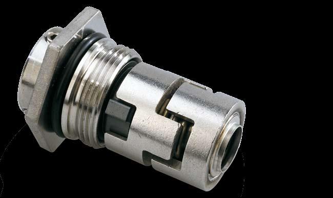
29 Type H Type K Type R Type H Balanced, cartridge O-ring seal unit with rigid torque transmission system This seal type is assembled in a cartridge unit which makes replacement safe and easy. Similar to the type D seal, the balancing makes this O-ring seal type suitable for high-pressure applications. Type K Balanced, rolled-metal bellows cartridge seal unit The metal bellows acts both as spring and torque transmission element. This seal type has only static rubber parts, with reduced risk of hang-up similar to type B. Type R Unbalanced O-ring seal, type A, with reduced seal face O-ring seal like type A but with a narrow seal face. Due to the narrow seal face of the unbalanced design, the balancing ratio exceeds that of seal type A. This reduces the pressure and temperature operating limits of the seal. Similar to type G, the seal performs well in highviscosity and anti-freeze liquids. 29
30 Mechanical shaft seal types and sealing systems Type O Type P Type O Two seals mounted in a back-to-back arrangement This seal arrangement incorporates a clean barrier fluid with a higher pressure than the pumped medium. This totally prevents leakage from the pumped medium to the environment and the clean barrier fluid secures a good lubrication of the seal faces of both seals. See descriptions on page 32. Type P Two seals mounted in a tandem arrangement This seal arrangement incorporates a clean flushing fluid with a lower pressure than the pumped medium. This cools the seal rings of the seal in the pumped medium and prevents precipitation from leakage. See descriptions on page

31 2. Sealing systems Some of the shaft seals described previously can be combined with specially designed pumps and in double seal arrangements. See the principles described below. Circulation Sometimes it is necessary to cool the seal faces of single mechanical shaft seals or remove deposits in the seal chamber. In such cases a circulation pipe from the pump discharge side to the seal chamber can be fitted. The cooling liquid flows from the seal chamber back to the pumped medium. This ensures a good exchange of liquid in the seal chamber. A pipe dimension of Ø10/Ø8 is sufficient. Internal circulation from the pressure side to the seal chamber can also be integrated in the pump design with the same result. See fig Fig 2.1: Circulation circuit for cooling a single mechanical shaft seal Double seals can be arranged in tandem with the seats in the same direction on the shaft, or back-to-back with the seats in the opposite direction on the shaft. The purpose of these designs is, among other things, to control temperature, pressure or flow in the cooling/heating lubricating liquid. 31
32 Mechanical shaft seal types and sealing systems Back-to-back arrangement with barrier fluid, seal type arrangement O This term is commonly used in sealing engineering to describe an arrangement with two shaft seals mounted in opposite directions. Between the two seals is a pressurised barrier fluid. The barrier fluid has several advantages to the product-side seal as compared to a single shaft seal. See. fig High pressure Low pressure Fig. 2.2: Grundfos CR pump with back-to-back seal arrangement The seal arrangement is suitable for poisonous and explosive liquids when no leakage from the pumped medium to the atmosphere can be accepted. The barrier fluid pressure is higher than the pump pressure, as a result of which any leakage will pass from the barrier fluid to the pumped medium. The barrier fluid pressure must be minimum 2 bar or 10 % above the pump medium pressure close to the seal. As the clean barrier fluid has a higher pressure, it also serves as lubricating liquid for all seal faces. The back-to-back shaft seal arrangement is particularly suitable for sticky media and/or liquids with many abrasive particles. The seal arrangement prevents the pumped medium from entering the seal gap and consequently prevents excessive wear. 32
33 Water or water mixed with glycerine is the most common liquid in closed pressurized back-to-back arrangements because it is non-poisonous and compatible with many types of pumped media. The barrier fluid chosen must always be compatible with the pumped medium. To maintain the overpressure in the barrier fluid in relation to the pumped medium pressure, various pressure sources can be used as described in the following sections. Fixed pressure A pressure vessel with fixed pressure in the barrier fluid with 10 % or 2 bar higher than the pressure in the pumped medium. See fig The advantages are as follows: compensates leakage cools the seals by means of natural convection or forced circulation 6 indicates the pressure in the barrier fluid possibly gives alarm when the barrier fluid level is low/high 4 7 allows refill of barrier fluid with pressure maintained in the vessel constant air pressure secures the barrier 1 fluid pressure 2 indicates temperature and liquid level Manual pump for refill 2. Level indicator 3. Thermometer 4. Manometer 5. Pressure vessel 6. Constant air pressure connection 7. Safety valve 8. High-/low-level switch Fig. 2.3: Pressure vessel with fixed pressure connected to a Grundfos CR pump with a back-to-back seal arrangement 33
34 Mechanical shaft seal types and sealing systems Fixed pressure obtained by means of a dosing pump Another way of obtaining a fixed pressure in the seal chamber is by means of a dosing pump. The pump automatically keeps the level set for the overpressure. This solution is mainly used in dead-end applications where cooling from the seal chamber is sufficient. See fig Seal chamber with barrier fluid 2. Pump 3. Membrane vessel 4. Dosing pump 5. Pressure switch 6. Manometer for barrier fluid 7. Reservoir with barrier fluid Fig. 2.4: Dosing pump maintaining a fixed pressure for back-to-back seal in a Grundfos CR pump 34


35 Pressure intensifier The Grundfos pressure intensifier automatically creates a pressure that is 2 bar higher than the pump medium pressure, independent of the specific pump medium pressure. The system maintains the overpressure automatically until it is empty. The intensifier requires a discontinuous working cycle, as it has to be refilled. The barrier fluid inlet must be fitted with a non-return valve to avoid back pressure to the source. See. fig.2.5. High pressure Low pressure BAR Connection to the seal chamber 3 BAR 4 Connection to the pumped medium Seal chamber with barrier fluid 2. Pump with pumped medium 3. Non-return valve, inlet side 4. Safety non-return valve (>5 bar) 5. Elastomer membrane Fig. 2.5: Pressure intensifier mounted on a Grundfos CR pump 35
36 Mechanical shaft seal types and sealing systems Tandem seal arrangement with flushing fluid, Seal type arrangement P The system contains a seal chamber with two shaft seals mounted in the same direction. The flushing fluid between the two seals has lower pressure as compared to the pumped medium and offers several advantages to the product-side shaft seal such as following: There is no evaporation in the sealing gap. This prevents the formation of deposits as well as crystallisation on the flushing fluid side. The flushing fluid lubricates and cools even when the pump runs dry or runs with vacuum. See fig High pressure Low pressure Fig. 2.6: Grundfos CR pump with a tandem seal arrangement 36
37 There are several ways of connecting the flushing fluid from an elevated reservoir to the seal chamber such as: Seal chamber with circulation from a reservoir Seal chamber with dead end connection from a reservoir Seal chamber with external flushing fluid Connect the seal chamber to a reservoir with circulation. The flushing fluid circulates by natural convection or a separate pump, lubricates and cools the seal faces. The flushing fluid in the reservoir must be replaced after a period of time due to contamination from the pumped medium. Connect the reservoir with a single pipe to the seal chamber. The flushing fluid lubricates the seal faces, but cools them less than by circulation. The flushing fluid in the reservoir must be replaced after a period of time due to contamination from the pumped medium. Allow the flushing fluid to circulate through the seal chamber to a drain. The flushing fluid cools and lubricates the seal faces effectively and makes it possible to monitor the seal leakage. Fig. 2.7: Flushing fluid examples 37
38 Mechanical shaft seal types and sealing systems Other sealing systems Sanitary shaft seals The demands on shaft seals in pumps designed for sterile and sanitary applications differ entirely from those made on other seals. Often the seal needs to comply with standards and regulations. Some of these are summerized in Chapter 6. In some instances the seal materials must comply with guidelines for cleanability and resistance to the pumped media and be capable of CIP, cleaning-in-place, and SIP, sterilisation-inplace. In addition, low roughness values and electro polished surfaces, marked yellow, are required on medium side components. Special attention must be paid to the elastomer components of the shaft seal. Elastomer components must withstand the pumped media and temperatures in the cleaning processes. The purpose of these requirements is to ensure that all shaft seal surfaces in contact with the pumped media can be cleaned. See figures 2.8, 2.9 and Fig. 2.8: Grundfos shaft seal type C for low cleaning requirements Vapour Fig. 2.9: Grundfos shaft seal type D for moderate cleaning requirements. Secondary seals have been modified, leaving no gaps Fig. 2.10: Example of complex sanitary agitator seal subject to the highest sterilisation and cleanbility requirements. The barrier fluid (green) can be steam condensate. Surfaces marked with yellow are electro-polished. Secondary seals on medium side have been modified, leaving no gaps 38
39 High-speed mechanical shaft seals Where speeds exceed m/sec, the seat must be the rotating part to reduce unbalance of the seal. See fig Other advantages of the rotating seat are that misalignment of the shaft causes the springs to adjust only once and prevent fretting of the sleeve under the O-ring. Fig. 2.11: (To the right) Example of a high-speed shaft seal for Grundfos BME pumping system Air cooled top for high temperatures For applications in woling high temperatures of the clean pumped medium such as hot water or thermal oil, it can be advantageous to extend the length of the pump. As a result, and air chamber will be formed below the seal chamber. Thanks to this arrangement, the standard shaft seal is located at a distance from the hot pumped medium, allowing the shaft seal to generate a stable lubricating film in the sealing gap. The exchange of pumped medium with pumped medium from the seal chamber is very low due to a throttle around the shaft. An automatic air vent valve is required to vent the seal chamber. This stand-alone sealing arrangement is independent of external connections. See fig Air vent valve Standard shaft seal Seal chamber Air chamber Pumped medium Fig. 2.12: (To the right) Example of a Grundfos CR pump with air-cooled top 39
40 Mechanical shaft seal types and sealing systems Magnetic-drive system The magnetic-drive system constitutes an entirely different type of sealing of a rotating shaft. For applications where it is absolutely necessary to avoid leakage from the shaft seal, an alternative to a back-to-back arrangement is a can that separates the pumped medium side from the atmospheric side. The magnetic-drive system incorporates an outer and inner rotor with magnets, separated by the can. The magnetic-drive system transfers the torque from the motor to the pump shaft. The system only has static O-rings to seal the clean pumped medium, free from magnetic particles. This stand-alone sealing arrangement is independent of external connections. See fig Stationary can Outer rotor with magnet and adapter to the motor Inner rotor with magnet and adapter to the pump shaft Pump shaft Fig. 2.13: Hermetically sealed system with magnetic-drive system 40
41 External-seal arrangement For the pumping of some types of clean and very aggressive but non-poisonous media, it can be an advantage to place the rotating part of the seal with the springs and seal driver outside the pumped medium. This type of balanced seal requires internal overpressure to keep the seal faces together. The clearance between shaft and seat is so large that an exchange of liquid to cool the seal faces can take place. See fig Seat Rotating seal ring PTFE bellows Pumped medium Fig. 2.14: Balanced external shaft seal for corrosive media Submersible motors The differential pressure between the inside and the outside of the submersible motor is small. Therefore mechanical shaft seals as well as lip seals can be used. However, the life of a mechanical shaft seals is much longer. Rotating shaft Stationary seat Rotating shaft seal Special arrangements are made to prevent excessive overpressure inside the motor. See. fig Fig. 2.15: Submersible motor with mechanical shaft seal 41

42 Mechanical shaft seal types and sealing systems 3. Selecting a mechanical shaft seal The mechanical shaft seal should be selected according to the operating conditions at the shaft seal location. These important factors must be considered when selecting a mechanical shaft seal: Shaft seal diameter Type of pumped medium Temperature Sealing pressure Shaft speed of rotation. Shaft seal diameter The shaft seal diameter must be selected to fit the pump shaft. If no seal with the required diameter is available, the shaft diameter can be changed with a bushing. Type of pumped medium The chemical resistance of the shaft seal materials to the pumped medium has to be considered. The viscosity of the pumped medium affects the lubrication and leakage of the seal. The viscosity of most media depends on the temperature. A single shaft seal can be used for a dynamic viscosity below 2500 cp (centipoise). For a higher viscosity, a back-to-back seal arrangement should be used. Temperature The elastomeric parts of the seal must be able to withstand the temperature of the medium around the seal. This might be different from the temperature of the pumped medium. If the temperature is above the boiling point of the pumped medium, lubrication is poor. This must be considered when selecting seal design and materials. Sealing pressure The sealing pressure is the pressure around the seal. For high pressures, a balanced seal should be used. Shaft speed of rotation If the speed of rotation is low, shaft seals with hard/hard material pairings might produce noise because the lubricating film in the seal gap is extremely thin. At speeds above 15 m/sec, a balanced seal with a rotating seat must be used to reduce seal unbalance. 42
43 In addition to these operating conditions, the content of abrasives and additives in the pumped medium might be relevant to consider when selecting seal ring materials. In some instances, the space available for the shaft seal is also an important factor. When selecting the right sealing arrangement around the mechanical shaft seal, also take into account the content of abrasives and the risk of build-up of wearing particles on the atmospheric side as well as the health hazards, explosion risk and toxicity of the pumped medium. Summary Mechanical shaft seals can be composed in many different ways with different performances. The type of seal selected depends on the pumped medium, temperature, pressure and speed. For harsh applications, single mechanical shaft seals can be combined using tubes, membranes, springs, valves and separate cooling liquid systems. 43
44

45 Chapter 3 Materials 1. Seal face materials 2. Seal face material pairings 3. Testing of shaft seals 4. Secondary seals 5. Materials of other shaft seal parts
46 Materials The preceding chapters have explained the composition and principle of operation of mechanical shaft seals. This chapter describes commonly used materials for the various parts of the mechanical shaft seal, including a number of tests of seals with different seal face materials. 1. Seal face materials Few materials are suitable for seal faces. To keep leakage as low as possible, the seal gap must be very small. As a result, the lubricating film is very thin. Consequently, the seal face materials must be able to withstand rubbing against each other at high load and speed. The best seal face materials have low friction, high hardness, good corrosion resistance and high heat conductivity. The choice of seal face materials is decisive of the function and life of the mechanical shaft seal. In the following, commonly used seal face materials will be described. Carbon graphite 50 µm 50 µm Fig. 3.1: Micrograph showing the material structure of antimony-impregnated carbon graphite Fig. 3.2: Micrograph showing the material structure of resin-impregnated carbon graphite Carbon graphite is a widely used seal face material thanks to its anti-friction properties. The material is suitable as counter face material to many other types of materials. Carbon graphite is a mixture of hard carbon and graphite. Impregnated carbon graphite Each carbon graphite manufacturer offers their own carbon graphite grades, depending on the source of the hard carbon, the graphite content, the grain size, mixing and baking. After pressing and baking, the carbon graphite contains 5 20 % porosities. To obtain a leak-proof product, the carbon graphite must be impregnated, using metals or resins as impregnating agents. 46
47 The metals used for metal-impregnation are low-melting-point types such as antimony (Sb), tin (Sn), lead (Pb) or alloys of these products. See fig According to EN 12756, the material code for this group is named A. See page 96. Resin-impregnation often involves a phenolic resin. See fig According to EN 12756, the material code for this group is named B. For special purposes, resin-impregnated carbon graphite can be further heat-treated to convert the resin to carbon. It might prove necessary to repeat the impregnation and heat treatment process several times to obtain a leak-proof carbon-impregnated carbon. Resin-bonded carbon graphite Resins containing up to 70 % carbon-graphite fillers can be injection moulded and used without baking. The material is called resin-bonded carbon. The resin-bonded carbon has a lower wear and chemical resistance than the resin-impregnated carbon. Properties In vacuum, the friction of graphite is high whereas it is low under normal atmospheric conditions. In hot water applications (> 100 C), metal-impregnated carbon graphite has a lower friction and higher wear resistance than similar types of resin-impregnated carbon graphite. The disadvantage of metal impregnation is the limited corrosion resistance. In addition, a drinking water approval cannot be obtained with metal-impregnated carbon graphite, see Chapter 6. xx mm xx mm The typical dry coefficient of friction value for carbon graphite against a hard seal face material is under normal atmospheric conditions. The stiffness and toughness of carbon graphite is low. These properties must be taken into consideration when designing and mounting mechanical shaft seals. In cold, clean water, a mechanical shaft seal with one carbon graphite seal face has a lifetime of several years. However, if the seal is used in hot water or solids-containing water, the seal must be changed at regular intervals. 47
48 Materials Aluminium oxide (alumina) 25 µm 25 µm Fig. 3.3: Micrograph showing surface of alumina Fig. 3.4: Micrograph showing etched surface of alumina Aluminium oxide is a ceramic material, also known as alumina. Alumina is commonly used as seal face material due to its good wear resistance and low price. Each supplier offers his own grades of alumina with different compositions of glass phase and various grain sizes. See figures 3.3 and 3.4. According to EN 12756, the material code for this group is named V. Properties The corrosion resistance in water is limited to a certain ph range, depending on the composition of the glass phase as well as on the purity. The best corrosion resistance is obtained with a % alumina. However, the price of the material increases drastically with the purity. Alumina is only suitable for low-load applications due to its low thermal conductivity as compared to tungsten carbide and silicon carbide. Alumina is mostly used as counter face to carbon graphite. The stiffness of alumina is high, but the thermal shock resistance is limited. Tungsten carbide (WC) 10 µm Fig. 3.5: Micrograph showing surface of tungsten carbide Fig. 3.6: Micrograph showing etched surface of tungsten carbide Tungsten carbide (WC) is the designation of the type of hard metals based on a hard tungsten carbide phase and usually a softer metallic binder phase. The correct technical term of tungsten carbide is cemented tungsten carbide. However, the abbreviated term tungsten carbide is often used for convenience, cemented being understood. See figures 3.5 and 3.6. According to EN 12756, the material code for this group is named U. Properties The hardness of WC is below that of most ceramics, whereas the wear resistance of the material is superior, mainly due to its high toughness. WC is a heavy material with a density of approx. 5 mm 14 g/cm³. Cobalt-bonded (Co) WC is only corrosion-resistant in water if the pump is made of a non-inert material such as cast iron. The corrosion resistance of some chromium-nickel-molybdenum-bonded WC types is similar to stainless steel EN (AISI 316). WC with less than 0.5 % binder phase has the highest resistance to corrosion, although the material is not resistant in media such as water containing hypochlorite. Due to its extremely high wear resistance, WC is the preferred seal face material for applications involving abrasive particles. 48

49 Silicon carbide (SiC) 100 µm 100 µm Fig. 3.7: Micrograph showing surface of dense silicon carbide Fig. 3.8: Micrograph showing surface of graphite-loaded silicon carbide SiC ceramics can be manufactured in many ways giving different properties. According to EN 12756, the material code for this group is named Q. See figures 3.7 and 3.8. The main SiC types are as follows: Direct-sintered. This SiC type is the most commonly used type for seal faces. Reaction-bonded. This SiC type has limited corrosion resistance in alkaline water due to the content of free silicon. Liquid-phase sintered. This SiC type has limited corrosion resistance in alkaline water due to the content of glass phase. Converted carbon graphite. This SiC type is manufactured from carbon graphite. It can be made as a thin SiC layer on the surface of the carbon graphite. Properties The direct-sintered SiC is brittle and requires careful handling. The material is light weight with a density of slightly above 3 g/cm³. The resistance to wear and corrosion is superior. The direct-sintered SiC has a typical porosity below 2 %, but also grades with pores have been developed. The pores are discrete, non-interconnected and dispersed in a controlled manner throughout the body of the material. The spherical pores act as fluid or lubricant reservoirs, helping to promote the retention of a fluid film at the interface of sliding component surfaces. This pore-based lubrication mechanism allows porous SiC to outperform conventional reaction-bonded and sintered SiC types in hot water. Sophisticated sintering or the addition of different fillers can imply variations in these standard SiC grades. Fillers can be added to obtain improved electric conductivity, more toughness or lower friction. Carbon or graphite inclusions can be used as dry lubricant to reduce friction. To use graphite inclusions successfully as lubricant, it is necessary to optimise the bonding between the SiC and the graphite as well as the size and amount of the graphite inclusions. 49
50 Materials Diamond coatings Diamond is the best known material for wear parts. Diamond has the highest hardness and thermal conductivity of any known material. In addition, it has an excellent corrosion resistance and a low friction. These properties make diamond the ideal material for seal faces. The major drawback of diamond is the price. Diamond coatings have been commercialised during the last decade. Coatings can be made as polycrystalline diamond and as a more amorphous carbon called diamond-like carbon (DLC). The polycrystalline diamond has the lattice structure of diamond, where each carbon atom has four neighbour carbon atoms equally spaced (Sp 3 bonds). See fig In DLC coatings, some of the carbon atoms are located in structures similar to the diamond lattice. Other carbon atoms are located in a structure similar to the lattice of graphite, which is hexagonal. See fig sp 3 = 4 covalent bonds sp 2 = 3 covalent bonds 6.70 Å 3.57 Å 2.46 Å Fig. 3.9: Carbon atoms in the lattice structure of diamond (Sp 3 bonds) Fig. 3.10: Carbon atoms in the lattice structure of graphite (Sp 2 bonds) Different variants of DLC coatings can be made, ranging in hardness from 1000 to 4000 HV. The DLC coating thickness ranges from 0.1 to 10 mm and affects the production costs to a great extent. When the coating thickness is small, the adhesion to the substrate must be very strong to prevent delamination when the DLC coating is used on a seal face. The best properties are obtained with thick polycrystalline diamond coatings on a hard substrate. However, if the counter face does not have a similar coating, it may suffer from wear. 50
51 2. Seal face material pairings Carbon graphite against WC Carbon graphite against WC is a widely used seal face material pairing. The carbon graphite/wc pairing withstands dry running for several minutes without causing damage to the mechanical shaft seal. The corrosion resistance depends on the carbon graphite grade as well as on the alloying elements of the WC binder. If the pumped medium contains hard particles, wear on the seal faces must be expected. Due to the favourable lubricating properties of carbon graphite, the seal is suitable for use even under poor lubricating conditions, such as hot water. However, under such conditions, wear on the carbon graphite face reduces seal life. The level of wear depends on factors such as pressure, temperature, pumped medium, seal diameter, carbon graphite grade and seal design. See fig All materials pairrings performance diagrams in Chapter 3, refer to 3000 RPM. [bar] mm [ C] [bar] mm [ C] [bar] 22 mm [ C] Operating hours Pos. before wear-out 1 More than 14, ,000-14, ,000-8,000 Fig. 3.11: Pressure/temperature diagrams showing operating life of Grundfos type H carbon graphite/wc shaft seals in water at three different shaft diametres Low speeds reduce lubrication between seal faces. This could have resulted in increased wear. However, due to the shorter running distance, the level of wear is unaltred in most cases. 51
52 Materials Carbon graphite against direct-sintered SiC Carbon graphite against SiC is another widely used seal face material pairing. The corrosion resistance of the carbon graphite/sic pairing is very good. The dry running properties are similar to those of carbon graphite/wc. The use of the carbon graphite/sic pairing for hot-water applications may cause heavy wear on the SiC face, depending on the grade of the carbon graphite and the water. The use of porous or graphite-loaded SiC against carbon graphite causes far less wear than with dense SiC. See fig [bar] 22 mm [ C] Operating hours Pos. before wear-out 1 More than 14, ,000-14, ,000-8,000 Fig. 3.12: Pressure/temperature diagrams showing operating life of Grundfos type H carbon graphite/sic shaft seal in water for a 22 shaft Carbon graphite against alumina Carbon graphite against alumina is a widely used seal face material pairing for massproduction low-cost seals. The corrosion resistance is often limited in water to a range between ph 5 and ph 10, depending on the alumina grade used. The dry-running properties are similar to those of carbon graphite/wc, but the performance in hot water is much poorer. See fig [bar] mm [ C] Operating hours Pos. before wear-out 1 More than 14, ,000-14,000 Fig. 3.13: Pressure/temperature diagrams showing operating life of Grundfos type C carbon graphite/alumina shaft seal in water for a 12 shaft 52
53 WC against WC A shaft seal with WC seal faces is extremely wear resistant. Being very robust, WC resists rough handling. The dry friction of WC against WC is high. Consequently, the WC/WC shaft seal material pairing has poor dry-running properties. A shaft seal with WC/WC seal faces running completely dry may be damaged within less than one minute of dry running. If certain pressure and temperature limits are exceeded, the seal may generate noise. The noise is an indication of poor lubrication, causing wear of the seal in the long term. The limits of use depend on seal diameter and design. The pressure/temperature diagrams of the various seals show areas where noise may occur. See fig [bar] mm [ C] [bar] mm [ C] [bar] 22 mm [ C] Pos. Range 1 Good performance 2 Risk of periodical noise in connection with start-up and variations in pressure and temperature 3 Periodical noise Fig. 3.14: Pressure/temperature diagrams of Grundfos type H WC/WC shaft seals in water showing performance range for three different shaft diameters Note: The running-in wear period with noise of a WC/WC seal face material pairing is up to four weeks. However, typically, no noise occurs during the initial operating days due to higher leakage 53

54 Materials SiC against SiC Being an alternative to WC/WC, the SiC/SiC material pairing is used where higher corrosion resistance is required. This material pairing has good resistance against abrasive particles due to the high hardness. The friction is high, but for some SiC grades containing solid lubricants, the friction is only half, giving some improvement of the dry-running properties. Seals incorporating these SiC grades may be capable of running several minutes without being lubricated by the pumped medium. The performances in hot water of seals incorporating porous SiC grades or SiC grades contaning solid lubricants can be seen in fig [bar] 22 mm [ C] Pos. Range 1 Good performance 2 Risk of periodical noise in connection with start-up and variations in pressure and temperature 3 Periodical noise Fig. 3.15: Pressure/temperature diagram of Grundfos type H SiC/SiC shaft seal in water showing performance range for a 22 shaft 54
55 3. Testing of shaft seals Various types of simple testing configurations, such as ring-on-ring or even pin-on-disc, can be used to evaluate whether a material is suitable for a machanical shaft seal. Such tests give information about the tribological performance of materials and may even reveal wear processes in the tribological system. To get an accurate picture of the performance of a shaft seal, the tests must be made under conditions resembling the application for which the seal is intended. Seal performance in hot water The lubrication of the seal faces in hot water is limited. This is due to the low viscosity of water at high temperatures as well as to the evaporation in the seal gap. The temperature and pressure limits for shaft seals can be obtained by means of extensive testing. Above these limits, noise from the seals may be expected and fatigue wear may occur. The pressure-temperature diagram, fig. 3.16, shows how the limits of good performance change with the velocity. At lower velocities, the limits shift towards lower temperatures. [Bar] min min min min [ C ] Fig. 3.16: Example of limits of stable friction of a shaft seal at different velocities The hot-water tests are performed in tap water. At pressures and temperatures below the relevant curve with stable friction, the seal faces are exposed to a minimum of wear. Some wear may be expected above the relevant curve. See fig Another way of showing temperature limits is to plot the wear rate as a function of the temperature at a fixed pressure. See fig Wear rate [Comparative] Dense SiC against dense SiC WC against carbon Graphite-loaded SiC against graphite-loaded SiC [ C ] Fig. 3.17: Comparative wear rate of seal faces with three different material pairings 55
56 Materials Dry running Dry running may cause serious damage to the seal. As it may be difficult to avoid dry running altogether in some applications, it is important to test the dry running performance of the seal. This can be done in a very simple way by running the shaft seal completely dry with a thermocouple attached to the seat or with thermographic equiment. The results obtained are slightly affected by the relative humidity of the air in the test room. Fig shows the temperatures measured on the seat of various dry-running seals. [ C ] Dense SiC against dense SiC Graphite-loaded SiC against graphite-loaded SiC (Manufacturer 1) Graphite-loaded SiC against graphite-loaded SiC (Manufacturer 2) [sec] Fig. 3.18: Temperature on seat at dry running of seals with different SiC grades As will be seen from fig. 3.18, dense SiC against dense SiC and graphite-loaded SiC aginst ifself (manufacturer 1) show poor dry-running performance, similar to WC against WC. The graphiteloaded SiC against itself (manufacturer 2) shows better dry-running performance. Dry-running tests show large variations, even within the same grade of SiC. Seal performance in water containing abrasive particles If both seal faces are made of hard materials such as ceramics, wear on the seal faces caused by abrasives are rarely observed. The seal gap in a mechanical shaft seal is typically below 0.3 micron. Theoretically, this means that only particles below 0.3 micron can enter the seal gap. In practice, the edge of a seal face is not completely sharp. Consequently, particles measuring a few microns are able to enter the seal gap. Normally, such small particles only cause a polishing wear on a hard/hard seal face material pairing. When one of the faces is a carbon ring, the edge of the seal face will wear and permit larger particles to enter the seal face. Such larger particles can be trapped in the carbon seal face and cause wear on the hard counter face. Seal performance in water containing glycol Water containing glycol may cause problems with leaking seals. The problems often arise due to additives such as inhibitors, antioxidants, alkalines, etc. Some additives such as silicates and phosphates may crystallize in the seal gab as hard particles. These hard crystallites cause wear on seals with one carbon face. See fig. 1.24a, page
57 Organic film binders, so-called inhibitors, adhere to all surfaces in contact with the liquid, including a major part of the seal face. Many inhibitors may build up sticky layers in the seal gap, resulting in leakage. Seals with WC/WC or SiC/SiC seal faces have better self-cleaning properties than seals with a carbon/sic seal face material pairing. A high closing force and a narrow width of the seal face reduces the risk of build-up of deposits. See type G, page 28, and type R, page 29. Fig shows the results of tests made with various seal face material pairings in water containing glycol with a high content of additives. Leakage rate [comparative] Low closing force High closing force WC/WC WC/Carbon Porous SiC/ Porous SiC Dense SiC/ Dense SiC Graphite-loaded SiC/ Graphite-loaded SiC Fig. 3.19: Leakage of seals with different material pairings running in water-based anti-freeze liquid To prevent a large seal gap with excessive leakage, a smooth surface finish is preferred. On the other hand, if the surface finish is too smooth, seizure of the seal faces may occur. Consequently, a compromise is often made with a different surface roughness of the two seal faces. The leakage rate of hard/hard material pairings is elevated until the seal faces have become smooth as a result of the running-in. Seals with one carbon seal face often have a lower, accumulated leakage during the runningin period because this period is shorter as compared to a seal with hard/hard material pairings. Seals with a high closing force have a shorter running-in period because the lubricating film is thinner. Seal performance in pure water Pure water can be aggressive to many ceramics. As far as direct sintered SiC is concerned, the grain boundaries containing sinter additives may be attacked in pure water. Damage is only observed on seal faces where high shear stresses may be achieved in asperity contacts. By controlling the sintering process, it is possible to achieve SiC grades that are more resistant in pure water. 57
58 Materials Fig shows the result of tests with dense SiC grades in 40 C demineralised water with a conductivity of 2 ms/cm. Special corrosion-resistant SiC grades show no failure during 11,000 hours of testing under these conditions. Failures [%] Dense SiC grade Special corrosionresistant SiC grade [hours] Fig. 3.20: Failure of SiC seals in demineralised water with a conductivity of 2 ms/cm Sticking of seal faces Very smooth and flat seal faces easily adhere to each other. In extreme cases, the adhesion is so strong that it prevents the motor from starting. Alternatively, it might cause the stationary seat to rotate in the secondary seal. Various mechanisms act on the adhesion between the seal faces. Physical adhesion Vacuum may occur when two flat and smooth surfaces are pressed tightly together. Consequently, a large axial force is required to separate the two surfaces, while a lower shear force is required to rotate the surfaces. The size of the shear force at start-up is equal to the force required for a very low rotational speed. See fig Coefficient of friction 0,6 0,5 0,4 0,3 0,2 0,1 WC against WC WC against SiC Graphite-loaded SiC against graphite-loaded SiC WC against carbon 0 50 Fig. 3.21: Coefficient of friction of different seal face material pairings in water, at low rotational speed [ C ] 58
59 Chemical adhesion of surfaces All surfaces subjected to the atmosphere have an oxide layer. See fig. 4.12, page 72. The equilibrium of the oxide layer may change when the surface gets into close contact with another surface or when it is exposed to the pumped medium. This change in equilibrium may involve chemical bindings to oxides from other surfaces. The more inert the oxide layer is to the surroundings, the weaker are the bindings to the counter surface. If the medium is aggressive to the seal face material, the corrosion products from the seal faces may form chemical bonds, resulting in high adhesion forces. To prevent such adhesion mechanisms, highly inert seal face material types such as SiC are preferred. Chemical adhesion involving adhesive agents If the pumped liquid contains ions that may precipitate on the seal face, the precipitations may act as glue between the seal faces. This adhesion mechanism may occur in hard water and liquids containing fugitive elements and can be reduced by using a carbon/sic seal face material pairing. Solid lubricant-loaded SiC materials also reduce adhesion because the solid lubricant is smeared in a thin layer on the seal faces, providing low shear forces. 4. Secondary seals As mentioned, it is important to choose the most suitable seal face material pairing to obtain the longest seal face life. Likewise, the secondary seals such as O-rings and bellows made of elastomer are essential for the right functioning and overall life of the mechanical shaft seal. Elastomers refer to polymers with a high degree of elasticity. The material is also known under the term rubber. Elastomers are the preferred choice of material for secondary seals due to their elastic properties. All these materials remain flexible within the operating range of temperature for the chosen mechanical shaft seal. The choice of elastomer is mainly based on the chemical composition and the temperature of the pumped medium. Besides, product approvals should be considered, see page 97. For an overview of temperature and chemical resistance of elastomeric materials, see fig The below-mentioned elastomers are used in mechanical shaft seals: NBR Acrylonitrile-butadiene rubber (NBR) belongs to the family of unsaturated copolymers. Varying the composition with more acrylonitrile increases the resistance against oil, but reduces the flexibility. Compared to natural rubber, NBR is more resistant to oil and acids. According to EN 12756, the material code for this group is named P. See page 96. HNBR Hydrogenerated acrylonitrile-butadiene rubber (HNBR) has the same good oil resistance as NBR and also good resistance to ozone, alkalis and amines. HNBR has a higher temperature limit in water than NBR. 59
60 Materials MVQ Silicone rubber covers a large group of materials in which methyl vinyl silicone (MVQ) is the main material. Silicone elastomers as a group have relatively poor tensile strength and poor wear and tear resistance. However, they have many special properties. Silicone in general has good heat resistance up to +230 C and good cold flexibility down to 60 C and good weather resistance. According to EN 12756, the material code for this group is named S. EPDM Ethylene-propylene diene monomer (EPDM) can be compounded to give many specific properties by varying the content of dicyclopentadiene, etylidene and vinyl norbornene. Compared to NBR, the material has very poor resistance to mineral oil, but excellent resistance to hot water. EPDM has a good resistance to polare liquids and poor resistance to apolare liquids. According to EN 12756, the material code for this group is named E. FKM Fluoro-carbon monomer (FKM) belongs to a family of rubbers designed for very high temperatures in many different liquids, due to the degree of fluorination. The material has poor resistance to hot water, but excellent resistance to oils and chemicals. FKM has poor resistance to polare liquids and good resistance to apolare liquids. According to EN 12756, the material code for this group is named V. FXM Flourinated copolymer (FXM) has a good chemical resistance and withstands a wide temperature range in hot water applications. FFKM Perflouroelastomer (FFKM) has the best chemical resistance of any known elastomeric material. The chemical resistance of FFKM resembles that of polytetraflouretylene (PTFE), and the elastic properties resemble those of rubber. The material solves many difficult sealing problems. FFKM is very expensive and can only be made in relatively simple geometries. According to EN 12756, the material code for this group is named K. Pumped medium Water, max. temp. [ C] Mineral oils, max. temp. [ C] Acids Alkalis Glycols Oils, fuel Solvents Elastomer NBR HNBR MVQ EPDM FKM FXM FFKM /- + +/- +/- +/- +/ / /- +/- +/ / /- - + Abrasive particles +/ /- +/- - Legend: + = excellent +/- = good under certain conditions - = poor - = disastrous Fig. 3.22: Overview of temperature and chemical resistance of elastomeric materials 60
61 5. Materials of other shaft seal parts Besides seal rings and elastomeric parts, the other parts of the mechanical shaft seal must also be selected according to the application. The number of parts of the mechanical shaft seal depends on the complexity of the seal design. Torque transmission parts Metal or polymer parts can be used to transfer the torque from the seal faces to the shaft and pump housing. This is of particular importance in case of hard/hard material pairings producing a large friction torque. Metal parts are often made of stainless steel with a corrosion resistance similar to or above the level of the other pump parts. Polymers or formed sheet metal is often used for mass-produced mechanical shaft seals. Powder-metal parts can be used for minor series and machined parts for small quantities. The mechanical shaft seal can be fastened to the shaft in different ways, but the most common is by means of small screws made of stainless steel or compression fitting. Springs and bellows Metal springs are used to press together the seal faces of O-ring shaft seals and rubber-bellows seals. Alloys of various levels of corrosion resistance are available. The bellows of the bellows seals can be used to provide the force that presses the seal faces together. This is very common for metal bellows, but also applies to polymer bellows and rubber bellows. Metal bellows are made of very thin sheet material. They are often cold-worked to obtain high yield strength. The material grain size must be small compared to the thickness of the bellows. The corrosion resistance grade of materials used for the bellows of above types must exceed that of other pump parts. Guiding elements High-pressure mechanical shaft seals may incorporate polymer or metal discs to minimise the gap between the rotating seal face and the shaft/sleeve. This reduces the risk of extrusion of the O-ring. See fig. 5.19, page 86. Bellows seals may incorporate polymer or metal guiding elements to centre the rotating seal ring on the shaft. Tubes, plugs and holders Tubes and plugs for cartridge seals can be made of metal or rigid polymers. This also applies to holders for O-rings and clamping rings for rubber parts. The material chosen depends on the corrosion resistance, strength and dimension stability required as well as the number of identical seals to be made. Summary Materials for mechanical shaft seals must be chosen according to the applications. Chemical resistance, temperature range and approvals must be considered. For seal face materials, the friction and wear properties are very important. 61
62
63 Chapter 4 Tribology 1. Lubrication 2. Wear
64 Tribology The science of friction, wear and lubrication is called tribology. The word is derived from the old Greek word tribos, which means rubbing. As described in Chapter 1, the seal rings of a mechanical shaft seal rub against each other with a very thin lubricating film. Tribology is a very old science. An old Egyptian inscription similar to fig shows how 172 slaves were able to pull a large statue on a sled. Fig. 4.1: Assuming the slege is made of wood sliding against wood, it can be calculated that this only is possible when lubricated with water. The man standing on the sledge is pouring water under the sledge to lubricate, and three more slaves are bringing water to the tribologist. 64
65 1. Lubrication The pressure distribution in the lubricating film is composed of a hydrostatic and a hydrodynamic contribution. The hydrostatic contribution arises due to the pressure difference between the pumped medium side and the atmospheric side. The hydrodynamic pressure is generated as a pumping action due to the sliding motion of the surfaces. The different lubrication regimes for hydrodynamic pressure are often described by means of a so-called Stribeck curve. See fig Coefficient of friction h 0 h~r h>> R Boundary lubrication Mixed lubrication Full-fluid-film lubrication R = Surface roughness Load Solid 1 Surface roughness, R h V Viscosity x velocity Load Solid 2 Lubricating film h h h Fig. 4.2: Stribeck curve showing different lubrication regimes At high velocities and not too high loads, the hydrodynamic pressure completely separates the sliding parts, allowing the formation of full-fluid-film lubrication. At lower velocities or higher loads, the hydrodynamic pressure is not sufficient to completely separate the sliding parts. In this situation, a mixed lubrication regime exists where part of the load is supported directly by the contact points of the surfaces. The topography of the surfaces affects where the mixed lubrication regime is reached. At even lower velocities or higher loads, the generated hydrodynamic pressure becomes insignificant. This lubrication regime is called boundary lubrication. The thickness of the lubricating film of the mechanical shaft seal must be very small to avoid excessive leakage. Consequently, the seal is always in the mixed- or boundary lubrication regime. 65
66 Tribology Duty parameter The mechanical shaft seal lubrication number on the x-axis in fig. 4.2 is called the duty parameter, G, defined by this formula: G = h w k Dp + p s h : dynamic viscosity w : angular velocity (2p n [sec -1 ]) k : balancing ratio of the seal Dp : pressure difference across the seal face p s : pressure in the seal gap caused by the spring. More details about duty parameter can be found in [1]. For small duty parameter values, the leakage is very low and the seal operates in the boundary lubrication regime. For large duty parameter values, even full-film lubrication can be achieved. Examples: The duty parameter, G, in boiler feed water is typically 10-8, in cold drinking water 10-7 and in crude oil The description of the lubrication regime with the duty parameter is not based on the calculation of a physical phenomenon, but more on empirical studies/methodes based on common practice. The following section provides further physically- based model descriptions of hydrodynamic lubrication. Hydrodynamic pressure distribution In the full-fluid-film lubrication regime, the friction between the surfaces with the relative velocity, v 0, is determined by the internal friction in the lubricating film. The shear resistance of a fluid is called viscosity, represented by the symbol, h,(eta). In the case of two flat surfaces, moving relative to each other at the velocity v 0 and separated by a fluid with the viscosity, h, the molecules of the fluid normally adhere to the surfaces. Consequently, the velocity of the fluid near a surface is almost identical with the velocity of the surface. When the distance between the surfaces is small, the fluid flow is laminar (no turbulence). In this case, the velocity increases linearly between the two surfaces; the force, F, required to keep the surface moving is proportional to the area of the surface, A, and to the shear strain, v 0 /h, where h, is the distance between the surfaces. See fig
67 F V = V 0 Area A h V = 0 Fig. 4.3: Velocity distribution and shear resistance, F, of a fluid film between two surfaces, h being the distance between the surfaces Thus, the shear stress F/A is proportional to the change of shear strain, v 0 /h: F/A = h v 0 /h Or more generally with t as shear stress: t = h v/ h (Newtonian fluids) In the case of parallel faces shown in fig. 4.3, the velocity distribution does not cause any pressure increase. If one of the surfaces is tilted slightly, the fluid will be forced into a smaller crosssection and therefore compressed. This will cause the pressure to increase and create a pressure distribution between the surfaces. See fig F N V 0 p (x, y) h 1 z y x h(x) Fig. 4.4: Slightly tilted moving surface creating a pressure profile h 2 For a given geometry, the pressure profile can be calculated using the Reynolds equation: p p x(h 3 (x) ) + = 6v. η x y (h 3 (x) y) h(x) x The lubricating film calculated depends on velocity, v 0, and load, F. However, in all cases the N pressure distribution generated between the surfaces will only be able to separate the surfaces by a distance comparable to the wedge height (h 2 h 1 ). See fig More details about lubrication theory can be found in [2]. 67
68 Tribology Waviness of seal rings To minimise leakage, the surface of the mechanical shaft seal rings must be flat. Consequently, no hydrodynamic pressure should be generated between the relatively rotating seal faces. Flat seal rings are normally obtained by lapping. However, even very accurately machined surfaces are not completely flat. Some surface waviness of the order of 1/10000 mm always persist. When there is a relative rotation between seal rings, the small waviness generates a hydrodynamic pressure. This pressure increases the lubricating film thickness, resulting in a higher leakage rate. See fig Leakage rate [ml/h] Waviness [µm] Fig. 4.5: Example of measured leakage as a function of waviness Waviness also appears as a result of mechanical and thermal distortion, but in most cases the resulting hydrodynamic pressure is not sufficient to completely separate the surfaces. The effect of waviness on the hydrodynamic pressure distribution is further discussed in [3]. The conclusion is that the safest compromise between lubrication and leakage is obtained by lapping the surface as flat as possible. Hydrodynamic tracks In shaft seals for very low-viscosity fluids like hot water and gases, the hydrodynamic lubrication can be increased by making tracks in the seal ring or seat. See figures 4.6 and 4.7. Lubricating film Thermally created wedge Hydrodynamic track Lubricating film Hydrodynamic wedge Fig. 4.6: Hydrodynamic tracks in seal rings for hot water Fig. 4.7: Hydrodynamic wedges in gas seal face 68
69 By thermal distortion, a wedge is created on the seal face near the tracks. See fig This type of tracks in the seal face pushes the evaporation zone closer to the atmospheric side of the seal [4]. Following each track, an area with increased pressure is created. This design allows the pumped medium to enter the seal gap very easily; a sealing zone still remains at the atmospheric side of the seal. A more efficient way of increasing hydrodynamic pressure is to machine small grooves in the seal face, making a wedge into the seal gap. This design is common in gas seals where a hydrodynamic pressure is desired even with an extremely low viscosity. See fig Roughness of seal rings Friction and wear depend on the actual area of contact and therefore on the surface topography. Roughness parameters such as R a values, indicate the average size of the roughness but not the shape of the topography. To describe the friction, wear and lubrication (tribological) properties of surfaces, the bearing area curve (BAC) is more suitable. The BAC describes the contact area with an imaginary plane as a function of the distance. This plane is pulled down in the surface, see fig The desired area in a certain depth is called the relative material ratio (Rmr) value in the relevant depth. Fig. 4.8 shows a bearing surface Rmr of 5 %, 40 % and 80 % for different depths. The percentages are calculated as the thick line in percentages of the total length Distance [mm] % 40 % 80 % Depth [µm] Fig. 4.8: Cross-section of surface showing how a BAC is obtained Different machining processes normally provide different BACs. See fig Bearing area [%] Depth [µm] Fig. 4.9: Examples of BACs for a grinded and a lapped surface Lapped Grinded 69
70 Tribology The lapped surface has a plateau with some valleys. Consequently, the bearing area rapidly increases with the depth until a large area has been reached. As opposed to the lapped surface, the area of the grinded surface is slowly increasing with depths indicating a more even distribution of valleys and peaks. Fig shows how the leakage rate differs according to the direction of the scratches on the surface. The arrows indicate the direction of rotation of the seal ring. According to fig. 4.10, the lubricating film can be pumped to the pumped medium side or to the atmospheric side, depending on the direction of the scratches on the surface. Leakage rate [ml/h] 4.5 Direction of rotation Roughness, R a [µm] Fig. 4.10: Measured leakage rate as a function of the roughness value, R a and the direction of the scratches on the surface The typical surface topography of seal rings is a statistic distribution of scratches in all directions obtained by means of a lapping process. A shiny surface with a small roughness can be produced by lapping. However, where both seal rings are made of hard materials, one of the seal rings should have a dull finish to prevent the seal rings from sticking together during standstill. For a dull surface finish lapped to an R a value of 0.2 the running-in period may last several days. 70
71 Surface texturing Surface texturing is one way of increasing the lubricating film in a seal running above the boiling point of the liquid (for example water above 100 C). No significant increase of leakage will take place when the seal runs below the boiling point, [7]. Pockets in the seal faces are filled with the pumped medium and therefore act as an extra reservoir, preventing the lubricating film from evaporating completely. Surface texturing can be achieved by laser machining or etching. If the seal rings are made of a material with closed pores, the seal faces appear as a textured surface. The advantage of porous seal rings is that the surface remains textured even when the seal rings are worn. Hydrostatic lubrication As described in Chapter 1, see the figures on page 14, hydrostatic pressure has a linear decrease through the seal gap with parallel faces, whereas the decrease is non-linear with a diverging or converging seal gap. See figures 1.21 and 1.22, page 19. Evaporation of the liquid in the seal gap also affects the pressure distribution. Vapour has a much lower viscosity than liquid, and therefore the evaporated liquid quickly escapes from the seal gap. On the other hand, the density of the evaporated liquid is much lower than the density of the liquid, which means that the volume increases by vaporisation. Thus vaporisation can increase the hydrostatic pressure above the linear decrease and push the evaporation zone closer to the atmospheric side. See fig Calculations of the hydrostatic pressure distribution in seal gaps with evaporation can be seen in [5]. Start of evaporation Stationary seat Stationary seat Start of evaporation Pump pressure Rotating seal ring Pump pressure Rotating seal ring Pump pressure Pump pressure Vapour pressure Atmospheric pressure Entry into seal Atmospheric pressure Entry into seal Exit to atmosphere Exit to atmosphere Fig 4.11: Evaporation in the seal gap can increase the pressure in the gap because the pumped medium expands when it evaporates. 71
72 Tribology Dry running Mechanical shaft seals for liquids must be lubricated and cooled by a liquid. The shaft seal will be damaged if it is allowed to run without a liquid. In the absence of a lubricating film in the seal gap, frictional heat is dissipated in the seal rings. The frictional heat causes the temperature of the seal rings to increase up to several hundred degrees Celsius after few minutes of dry running. The high temperature damages the elastomeric secondary seals. The temperature reached and the time it takes to reach this temperature depend to a large extent of the materials of the seal rings and the design of the seal. Shaft seals with one carbon seal ring might be capable of running dry for several hours without severe damage to the seal components. 2. Wear Wear is an undesired removal of material from a surface. A number of processes may lead to wear of a surface. These processes are categorised into four common types of wear [6]: Adhesive wear Abrasive wear Corrosive wear Fatigue wear. Adhesive wear Even macroscopic smooth surfaces are rough on an atomic scale. When such two surfaces are brought together, contact is made at relatively few isolated asperities. When a normal load is applied, the local pressure at the asperities becomes extremely high. In the absence of lubricating films on the surface, the surfaces adhere to each other. However, very small amounts of contaminants prevent adhesion. See fig Tangential motion of one surface relative to another might cause the surface film to disperse at the point of contact; cold welding of the junction can take place. Asperity Surface film Surface Contaminant layer, 5 nm Adsorbed gas layer, 0.5 nm Substrate Oxide layer, 10 nm Fig. 4.12: Surface of a material with contaminants Continued sliding causes the junctions to be sheared and new junctions to be formed. This is the adhesive wear process. The surface topography is very important to prevent adhesive wear as it determines the contact stress in asperities. The materials chosen for seal rings should not be easily welded together to prevent adhesive wear. 72
73 Abrasive wear Abrasive wear or abrasion is the ploughing of a tip from one material in another material. When asperities in one surface remove material in another surface, it is a two-body abrasion. The result of this wear is a surface with regular grooves. The abrasion process is called erosion, when a particle impinges the surface and the kinetic energy of the particle is used to remove material from the surface. In this case, a more random surface similar to a grit blasting can be observed. Hard particles trapped between two sliding surfaces may cause severe damage. This is called three-body abrasion. See fig Velocity Hard particle Debris Fig. 4.13: Three-body abrasion Three-body abrasion also appears as regular grooves in the surface. See fig. 5.12, page 84. The resistance against abrasion depends on the ductility of the surface as well as the hardness of the surface compared to the hardness of the tip causing the abrasion on. The more ductile the surface, the more tendency to plastic deformation instead of debris removal, this results in less wear. Corrosive wear When surfaces rub against each other in corrosive environments, reaction products may be formed on the surface. These products often have a low adherence to the surface and can be removed by the rubbing and eventually cause abrasive damage. Corrosive wear can be observed on shaft seals with hard seal faces in a corrosive medium. This can be due to corrosion of a binder phase releasing hard grains from the material. Fatigue wear Surfaces repeatedly subjected to large stresses might wear on account of fatigue. Stresses can be caused by the mechanical load which is typical for roller bearings. The largest stresses to seal rings are caused by thermal gradients produced by frictional heat and evaporation. Wear on SiC faces may occur in hot water. It may look like abrasive wear because SiC grains are pulled out due to thermal fatigue of SiC. The grains pulled out cause abrasion of the seal faces, leaving the impression that abrasive wear is the cause of the wear. This type of wear is only seen above the pressure and temperature limit for stable friction. The thermal fatigue of SiC may be a complex process involving evaporation, cavitations and corrosion. 73
74 Tribology Summary This section describes how pressure can be established in the lubricating film and how different mechanisms can lead to wear. Pressure in the lubricating film is increased when there is a wedge in the seal face in the direction of the moving faces or if evaporation occurs between the seal faces. A wedge will appear with seal ring waviness, hydrodynamic tracks or with surface texture. The most common types of wear are: adhesive wear with seal faces sticking together, abrasive wear due to ploughing, corrosive or fatigue wear, or a combination of these wear types. [1] B.S. Nau: Hydrodynamic Lubrication in Face Seals, 3th Int. Conf. on Fluid Sealing (1967). [2] Bernard J. Hamrock: Fundamentals of Fluid Film Lubrication. [3] A.O. Lebeck: Face Seal waviness, prediction, measurement, causes and effects, 10th Int. Conf. on Fluid Sealing (1984). [4] L.E. Hershey: Extending Mechanical Seal Service Life when operating in hot Water, 7th Int. Conf. on Fluid Sealing (1975). [5] P. Waidner: Evaporation in the gap of face seals Theoretical calculations and results for hot water applications, 12th Int. Conf. on Fluid Sealing (1989). [6] J.T. Burwell: Survey of possible wear mechanisms, Wear 1 (1957), p [7] I. Etsion: A Model for Mechanical Seal with Regular Microsurface Structure, Tribology Transactions, vol. 39 (1996), p


75 Chapter 5 Failure of mechanical shaft seals 1. Introduction to failures 2. Lubrication failures 3. Contamination failures 4. Chemical, physical degrading and wear 5. Installation failures 6. System failures 7. Shaft seal failure analysis
76 Failure of mechanical shaft seals 1. Introduction to failures Failure of the mechanical shaft seal is the most common cause of pump downtime. The shaft seal is exposed to widely varying operating conditions. Sometimes operating conditions change to become quite different from the specific conditions for which the seal was intended. The diagrams below show that shaft seal failure is by far the most common cause of pump system failure. See figures 5.1 and 5.2. Causes of pump failure Pump repair costs 3 % 1 % 3 % 5 % 2 % 5 % 1 % Shaft seal Miscellaneous Impeller Operation Coupling Housing Roller bearings 15 % 30 % 18 % 34 % 39 % 44 % Fig. 5.1: Analysis of pump failure. Mechanical seals account for 39 % of pump failures. [1] Fig. 5.2: Analysis of pump repair costs. Mechanical seals account for 44 % of pump repair costs. [1] Typical shaft seal failures depend highly on the seal type and material pairing. O-ring-type shaft seals with dynamic O-ring and one seal ring in carbon-graphite typically have problems with wear on seal faces and seal hang-up, which prevents axial movement of the dynamic O-ring and seal ring. Mechanical shaft seals with hard/hard seal face material pairings usually experience problems associated with dry running. Detailed information is required to make a failure analysis of a damaged shaft seal and subsequently prevent new failures. On the damaged shaft seal, it is possible to observe what is damaged, but the reason for the damage must often be found on the basis of knowledge of the pump and the application. This information should be recorded in a damage report, including details on the operating conditions of the equipment and components around the shaft seal. See shaft seal failure analysis, pages In the following, examples of common causes of failure of mechanical shaft seals will be discussed. 76


77 2. Lubrication failures Proper functioning of mechanical shaft seals with hard/hard seal face material pairings depends on lubrication by the pumped medium. Dry running and poor lubrication can produce the results described below. Dry running Fig. 5.3: Surface damage due to high temperature on EPDM and FKM secondary seals Poor lubrication Dry running occurs when there is no liquid around the seal, either due to the absence of pumped medium in the pump or poor venting, resulting in the formation of air around the seal. The absence of lubricating film causes the friction between the seal faces to increase. Consequently, the temperature rise dramatically. As there is no pumped medium in contact with the seal rings, the heat must be transported away through the seal. Many seals with hard seal faces reach a temperature of several hundred degrees Celsius on the seal faces within few minutes. The typical damage caused by dry running is burnt elastomeric parts. The damage occurs where the O-ring is in contact with the hot seal ring. See fig Fig. 5.4: Severe thermal cracks in WC seal face caused by poor lubrication Similar to dry running, the frictional heat generated on the seal faces as a result of poor lubrication may also cause problems. Poor lubrication may occur when the viscosity of the pumped medium is very low or if the temperature is well above the boiling point at atmospheric pressure. Under these conditions, the frictional heat dissipating in small areas on the seal face can be very high. The alternating local heating and cooling of the seal faces may cause small, radial, thermal cracks in the seal faces. See fig
78 Failure of mechanical shaft seals Noise When lubrication is poor or totally absent, shaft seals with seal rings made of hard materials tend to generate a loud noise. Depending on the seal design, the hard materials used and the system, the noise can be at a constant level of intensity and frequency or be more random. When noise is generated from the mechanical shaft seal, some parts of the seal vibrate. This may reduce the life of the seal. Metal bellows seals in particular have a tendency to fatigue on account of vibrations. 3. Contamination failures The pumped medium is often a mixture of miscible liquids and a solution of solids, in addition to small suspended insoluble particles. The lubricating film in the sealing gap is subjected to large gradients in temperature, pressure and velocity. This increases the risk of precipitation and sedimentation in or near the sealing gap. Hang up Fig. 5.5: Sketch of seal hang-up due to blocking of the axial movement of the dynamic O-ring Hang-up of a mechanical shaft seal means that the axial movement of the rotating part of the shaft seal is blocked. Hang-up mainly occurs in connection with O-ring-type seals, but is also seen in connection with bellows seals, although the underlying mechanism is different. In connection with O-ring-type shaft seals, settlements or precipitations may build up on the shaft beside the O-ring, preventing the O-ring from sliding freely. When the temperature or pressure in the system change, the dimensions of pump parts change likewise. As a result, the O-ring must be able to slide freely on the shaft or sleeve to continue to function correctly. See fig If a rubber bellows seal is operated at temperatures close to the permissible maximum limit of the rubber type and close to the maximum permissible pressure limit of the seal, the inner surfaces of the bellows tend to stick to the shaft. This results in hang-up. The same failure mechanism results in hang-up of O- ring-type shaft seals, as the dynamic O-ring may stick to the shaft. Some rubber types such as FKM have a high tendency to stick to stainless steel. A hang-up failure is not always possible to observe during an analysis, as the seal has already been disassembled. 78


79 Opening of the sealing gap Fig. 5.6: Deposits on carbon graphite seal face Some suspensions and solutions tend to cause build-up of scattered deposits on the seal faces. As the deposits only cover part of the seal faces, the sealing gap opens correspondingly. The result is a leaking shaft seal. The leakage is small at the beginning, accellerating as more liquid passes the sealing gap. The settlement accelerates, because the temperature is higher on the surface of the already anchored deposits. See fig Clogging Fig. 5.7: Metal bellows seal clogged by lime scale build-up When the pumped medium has a high content of suspended particles and fibres, the seal can fail due to precipitation or consolidation of the particles and fibres on or at springs, bellows, seal-drivers or O-rings. The sedimentation rate is affected by the pumped medium and the flow conditions around the seal. In extreme cases, the sedimentation on metal bellows shaft seals may prevent the axial spring action of the bellows. Subsequently, the seal can open when the operating conditions are changed. See fig If a change in operating conditions necessitates an axial compression of a bellows clogged by sediments, the closing force of the seal can be extremely high. This may result in excessive mechanical stress on the seal components or failure due to poor lubrication. 79
80 Failure of mechanical shaft seals Particles and deposits Small amounts of hard particles on the seal faces result in increased wear, especially when using hard/soft seal face material pairings. In such cases, small, hard particles might be squeezed into the soft seal ring from where they act as a grinding tool on the hard seal ring. Impurities between seal faces result in a high leakage rate, permanently or until the impurity has been grinded and flushed away. As an example, a human hair is 50 to 100 µm thick, as compared to the 0.3 µm (height) of a sealing gap operating under normal operating conditions. Thus, a human hair of 60 µm is 200 times the width of a normal sealing gap. The leakage rate is proportional to the sealing gap raised to third power, see formula 2, page 18. If a human hair is trapped between seal faces, the leakage rate will be 200³ = 8,000,000 times the leakage rate of a shaft seal with clean seal faces. Sticking/seizure Sticking (British) and seizure (American) are two different terms with the same meaning. In the following, we shall use the term sticking. Sticking occurs when the two seal rings are locked or partially welded together. The locked state results in a failure if the interconnection is higher than the starting torque of the motor. It may also result in mechanical damage of seal parts. Sticking can have different causes. Mainly hard/hard seal face pairings have a tendency to sticking. The main causes of sticking are precipitation of sticky materials from the pumped medium on the seal faces or corrosion of the seal faces. Sticking is only possible on shaft seals of pumps with start/stop operation. The period it takes for the seal rings to stick together ranging from a few hours and up, depending on the pumped medium. The process accellerates at elevated temperatures. 4. Chemical, physical degrading and wear All parts of the mechanical shaft seal must have adequate resistance to the chemical and physical environment to operate properly during the expected working life. Elevated temperatures and severe chemical or mechanical loading reduce the expected working life of the seal. This applies up to certain limits; above these limits, degeneration and malfunction will rapidly occur. The polymer elastomeric parts may exhibit many signs of degradation, including blisters, cracks, voids or discoloration. In some cases, the degradation can be ascertained only by measuring the physical properties. Incompatibility with the chemical and/or thermal environment contributes to the degradation. 80
 and a swollen EPDM O-ring (right) exposed to water containing mineral oil Swelling of rubber is an increase in volume and a decrease in hardness due to absorption of a")

81 Swelling of rubber parts Fig. 5.8: A fresh EPDM O-ring (left) and a swollen EPDM O-ring (right) exposed to water containing mineral oil Swelling of rubber is an increase in volume and a decrease in hardness due to absorption of a solvent. The volume increase depends on the type and grade of rubber, the type and concentration of the solvent as well as the temperature and time of exposure. In extreme situations, the linear dimensions of a swollen rubber part can be doubled. The function of many types of shaft seals depends to a great extent on the geometry of the rubber parts. Consequently, even tiny changes in dimensions can be critical. The reduction in hardness is associated with changes in other mechanical properties of the rubber. The commonly used EPDM rubber material shows a high degree of swelling when exposed to mineral oil. EPDM swelling takes place irrespective of the concentration of mineral oil in water, however, the lower the concentration level, the longer the period of operation before failure. See fig Other types of rubber also show swelling when exposed to noncompatible liquids. Volume swelling, as described above, is only one indication of incompatibility with the pumped medium and may be based on the solubility parameter alone. In addition, attack by the pumped medium on the back-bone and/or cross-link system of the elastomer may appear as a change in physical properties such as tensile strength, elongation at break and hardness. Elevated temperatures and extended exposure times may create more aggressive conditions. 81


82 Failure of mechanical shaft seals Ageing of rubber parts In addition to the above degradation process, an ageing process takes place. Ageing often results in a change in physical parameters such as tensile strength and hardness. Ageing is divided into these two categories: shelf-ageing atmospheric ageing. Shelf-ageing is basically oxidative degradation. Apart from the obvious influence of oxygen, the catalytic effects of heat, light, internal and external stresses or strains and pro-oxidant metals should be considered. As opposed to shelf-ageing, atmospheric ageing is characterised by the attack of ozone on the rubber. It is essential to know that this is not merely another form of oxygen-induced degradation the mechanism is quite different. If the rubber is exposed to any sort of stress, the result is atmospheric cracking in which the cracks are perpendicular to the direction of elongation. Atmospheric ageing is well-known from old bicycle or automotive tires. Here several concentric cracks can be observed where the tire has the highest deflection during operation. Explosive decompression Corrosion Explosive decompression occurs on polymeric parts as blisters, pits or pocks on its surface. When the pumped medium has a high partial pressure of a gas-phase, the gas diffuses into the rubber. If the pressure is decreased and the absorbed gas in the material cannot escape as fast as the pressure is decreased, an internal overpressure builds up. If this pressure exceeds the strength of the material, an explosion takes place due to the decompression. An elastomer with high gas solubility and low mechanical strength is exposed to explosive decompression. 100 µm Seal face 2 mm µm µm Fig. 5.9: Selective corrosion in cemented tungsten carbide. The metallic binder phase is corroded resulting in reduced wear resistance Most seal rings materials are made of composite materials. In order to prevent selective corrosion, all phases of the seal ring material must be resistant to the pumped medium. Corrosion in cemented tungsten carbide is typically seen as an attack on the metallic binder phase. The result of this attack is loss of the 82


83 mechanical properties, including decrease in wear resistance. When the metallic binder phase disappears, the surface becomes matted. The selective corrosion of the binder phase may induce stresses, leading to cracks in the seal rings. See fig On other surfaces of the seal rings, heavy erosion can occur where the binder phase is corroded. See fig In stainless steel pumps and pipe systems, tungsten carbide with cobalt binder corrodes in tap water. Fig. 5.10: Corrosion of the binder phase followed by severe erosion on a tungsten carbide seal ring with cobalt binder phase In ceramic materials such as aluminium oxide, the process of a corrosion attack often dissolves or oxidises the glass phase, resulting in a decrease in wear resistance. When the glass phase has disappeared from the surface of the seal ring, the porosity increases. This affects the mechanical strength of the seal ring. The strength can be reduced with a few percentages or it can totally crumble, depending on the material grade and pumped medium. Corrosion seldom occurs on the metal parts of the seal in stainless steel pumps. The reason is that seal metal parts are commonly made of a higher grade of stainless steel than other pump metal parts. Wear Fig. 5.11: Normal wear on surface of tungsten carbide seal ring Because the thickness of the lubricating film is of the same order of magnitude as the surface roughness, the seal faces will wear to some extent. This normal wear on well-performing seals will be so small that the seal will be able to survive for many years. See fig In special cases, wear can cause problems, but often seals work perfectly with severe wear up to mm, even with heavily grooved seal faces, as long as the axial flexibility of the seal ring is maintained. 83


84 Failure of mechanical shaft seals Wear, continued Fig. 5.12: Deep seal face grooves close to the pumped medium side Fig. 5.13: Grooves on seal faces at the evaporation zone Deep seal face grooves close to the pumped medium side indicate that hard particles from the pumped medium have entered the sealing gap. See fig Deep grooves close to the atmospheric side indicate that hard precipitates from the pumped medium have been created where the lubricating film evaporates. See fig Installation failures Some mechanical seal failures come from wrong mounting and handling. Examples can be shaft misalignment, seats not mounted perpendicular to the shaft, axially moving shaft and wrong assembly length, etc. Misalignment Centre Run-out Fig. 5.14: Well-aligned shaft seal Fig. 5.15: Shaft seal with radial run-out The position and width of wear tracks on the seat indicate various problem areas. If the width of a wear track on the seat is the mirror of the sliding face of the opposite seal ring, the shaft seal seems to be well aligned with no run-out of the shaft. See fig If the sliding face of the seat is broader than the rotating sliding face, a wider track on the seat all way around indicates a high run-out of the shaft. See fig This can also be seen if, for some reason, there is an unbalance of the rotating mass. An uneven depth of the wear track around the seat indicates a tilted/crooked mounting of the seat. See fig


85 Tilted Fig. 5.16: Uneven depth of wear track on the seat caused by tilted/crooked mounting Fig. 5.17: Wear on dynamic O-ring at the point where it seals against the shaft Abnormal wear on the dynamic O-ring is observed, if the seat of an O-ring seal is tilted. Wear on the dynamic O-ring is followed by axial scratches on the inner surface. See fig Wear on the dynamic O-ring is caused by a movement between the shaft or the sleeve and the O-ring. The movement can be an axial movement of the shaft (vibration) or a misalignment of the stationary seat (the seat face is not perpendicular to the shaft). Fig. 5.18: Corrosion on shaft below dynamic O-ring caused by axial movement of the shaft Axial movement of the shaft caused by vibration or a tilted seat, can cause wear on the shaft or sleeve below the dynamic O-ring. The O-ring rubbing on the shaft continually removes the protecting oxide layer on the shaft, causing corrosion. See fig Assembly Fitting Where a mechanical shaft seal is installed in rotating equipment, the axial movement of the shaft must not exceed the shaft seal flexibility. Axial movement of the shaft exceeding the permissible flexibility of the rotating part of the mechanical shaft seal may cause extended wear on the seal rings or permanent damage to individual parts of the shaft seal. Many shaft seals have assembly lengths according to standards. This allows users to change from one type of seal to another with improved performance for the actual application. Even if two different seals have the same total length, the sliding faces are not necessarily placed at the same height. If components from two different seals are mixed, the result can be inferior or excessive compression of the seal. 85


86 Failure of mechanical shaft seals 6. System failures When operating pump systems, the operating parameters may differ slightly from what the system was designed for. A change in operating conditions may affect the seal performance. These parameters affect the performance of a mechanical shaft seal: the pressure in the seal chamber the temperature around the shaft seal in the seal chamber the pumped medium the speed the shaft seal dimensions. If the above parameters are not correct for the application in question, the result may be malfunction or damage to the shaft seal. Pressure Temperature Fig. 5.19: O-rings extruded on account of high pressure The pressure at the pumped medium side of the seal must be within limits defined by the seal design, the materials and the pumped medium. When the pumped medium pressure on the shaft seal exceeds the level it was designed for, various failures may occur: The friction between the seal rings may increase and cause damage either directly due to the friction forces or to the secondary seals in the seal. Extruded O-rings is a commonly known failure mechanism. If the temperature approaches the maximum operating limit of the rubber, the rubber material becomes softer and thus susceptible to extrusion. See fig Fig. 5.20: Removal of frictional heat by means of circulating the pumped medium across the shaft seal in the seal chamber The friction between seal faces in normal operating conditions generates heat. Consequently, the temperature in and close to the seal is higher than the temperature of the pumped medium. 86
METAL BELLOWS SEAL 3604/3604HTC/3604HTCDP Technical Specification
 A Inner Bellows Assembly B Primary Ring C Packing A B D Inner Mating Ring C D E Flow Guide E F Spiral Wound Gasket G Inner Gland H Dual Scroll Pumping Device I Outer Bellows Assembly J Packing Follower
Appendix B. Glossary of Steam Turbine Terms
 Operator s Guide to General Purpose Steam Turbines: An Overview of Operating Principles, Construction, Best Practices, and Troubleshooting. Robert X. Perez and David W. Lawhon. 2016 Scrivener Publishing
Uni-Seals Product Catalog
 Uni-Seals Product Catalog www.uni-seals.com 0 Index Spare Parts SP1001 Reaction bonded silicone carbide.. 2 SP1002 Pressureless sintered silicone carbide 2 SP1003 Silicone carbide + carbon.. 2 SP2000 Tungsten
1604/2609/3609 TYPE 1604/2609/3609. First Edition API 682 Type C Sealol Metal Bellows Seals. Product Description. Performance Capabilities
 A Inner Bellows Assembly B Insert C Inner Mating Ring D Packing E low Guide Inner Gland G Spiral Wound Gasket H Pumping Ring I Outer Bellows Assembly J Packing ollower K Sleeve L Outer Gland M Outer Mating
Mechanical Seals NINGBO DPM FLUID TECHNOLOGY CO., LTD A SEALS AND BEARINGS ENGINEERING COMPANY
 Mechanical Seals NINGBO DPM FLUID TECHNOLOGY CO., LTD A SEALS AND BEARINGS ENGINEERING COMPANY Company Profile Ningbo DPM Fluid Technology Co., Ltd is a seals and bearings engineering company located in
FLOWSERVE CORPORATION Guardian Pumps. Centrifugal ANSI Pumps Product Training Program
 FLOWSERVE CORPORATION Guardian Pumps Centrifugal ANSI Pumps Product Training Program April 2017 Sealless Pumps Definition A pump that is designed with no externally actuated shaft penetrating the pump
PTFE semi-finished products and finished parts
 Material characteristics PTFE = Polytetrafluorethylene PTFE is excellently suited as a construction material for the chemicals industry. It temperature resistance ranges from -190 C to +250 C, and it can
LIQUID-SPECIFIC PRODUCT LINE: ABRASIVE LIQUID PUMPS SERIES DESCRIPTION OPERATING RANGE: IMPROVEMENTS NOMINAL FLOW RATES:
 SERIES 4624B (Cast Iron - Replaces Series 4625 Models) Page 410.1 Issue K SERIES DESCRIPTION The Abrasive Liquid Series heavy duty internal gear pumps utilize hard parts in key wear areas, combined with
Automotive & Mechanical Applications Broad Base. Best Solutions.
 Carbon and Graphite Materials for Mechanical Seals Automotive & Mechanical Applications Broad Base. Best Solutions. Tribological Behavior Friction Friction depends on surface finish of the mating surfaces
UNIVERSAL PRODUCT LINE: STAINLESS STEEL MAG DRIVE PUMPS TABLE OF CONTENTS SERIES DESCRIPTION RELATED PRODUCTS OPERATING RANGE
 SERIES 827A Section 703 Page 703. TABLE OF CONTENTS Features & Benefits...2 Model Number Key...2 Port Location Options...2 Cutaway View & Pump Features...3 Materials of Construction...4 Special Materials
UNIVERSAL PRODUCT LINE: CAST IRON MAG DRIVE PUMPS TABLE OF CONTENTS SERIES DESCRIPTION RELATED PRODUCTS OPERATING RANGE
 UNIVERSAL PRODUCT LINE: SERIES 8124A Section 1403 Page 1403.1 Issue A TABLE OF CONTENTS Features & Benefits...2 Model Number Key...2 Materials of Construction...4 Special Materials & Options Selection
Carbon slide bearings
 Schunk Carbon Technology Carbon slide bearings schunk-carbontechnology.com Content Schunk Carbon Technology 03 Fields of Applications 04 Characteristic properties 05 Load capacity 05 Dry-running slide
INTRODUCTION TO WELDED METAL
 INTRODUCTION TO WELDED METAL BELLOWS SEALS 1 Welded metal bellows mechanical seals have earned their place in today s fluid sealing marketplace because of their reliability and wide range of uses. Bellows
Ceramic Linear Bearings
 Ceramic Linear Bearings ov-ceramic-bearings-divider - Updated - 18-09-2017 163 Ceramic Linear Bearings Technical Information Ceramic linear bearings Self-lubricating These ceramic coated linear bearings
single stationary environmental cartridge mechanical seals f4s100 TM & ANSI+ f4s100 TM series
 single stationary environmental cartridge mechanical seals f4s100 TM & ANSI+ f4s100 TM series 4seals plc, mount street, bradford, west yorkshire. bd3 9sn united kingdom Tel: +44 (0) 1274 720775 Fax: +44
MJ / MJ-B Series Standard Non Metallic Magnetic Drive Pumps
 MJ / MJ-B Series Standard Non Metallic Magnetic Drive Pumps PFA PVDF CFRPVDF ISO 8 ISO 5199 EN 28 Lined Type Sealless Corrosion Resistant Chemical Pumps MJ / MJ-B Series Sealless, Fluoropolymer Lined,
Model EVMS Vertical Multistage Pumps for the Global Market
 New Products & New Techniques Model EVMS Vertical Multistage Pumps for the Global Market Hiroyuki KAWASAKI*, and So KUROIWA* Abstract As key products for the global market, new model EVMS stainless vertical
MODULE 3 - BEARINGS LECTURE 1- SLIDING CONTACT BEARINGS INTRODUCTION
 MODULE 3 - BEARINGS CONTENTS LECTURE 1- SLIDING CONTACT BEARINGS INTRODUCTION 1. Sliding contact bearings - introduction. 2. Sliding contact bearings - advantages and disadvantages. 3. Classification of
since 1928 ALBIN PUMP RB INTERNAL GEAR PUMP SERIES since 1928
 since 1928 ALBIN PUMP RB INTERNAL GEAR PUMP SERIES since 1928 THE LEGEND To come up with a really good product demands plenty of knowledge and fresh, innovative ideas. Yet most important of all is to
Installation of stuffing box packings
 Installation of stuffing box packings 1. Selection of best suited packing style 2. Determination of correct packing cross section 3. Calculation of the correct length of packing rings 4. Cutting the packing
2/24/2011. Energy Efficiency. Fluid Sealing Association. The Beginning. Fluid Sealing Association
 Sealing Systems Energy Efficiency Fluid Sealing Association Friction is Only The Beginning Fluid Sealing Association 1 Sealing Systems Impact Efficiency Friction losses are only the beginning There is
Setting Mechanical Seals
 GB Setting Mechanical Seals Style 890 Single Stationary Multiple Spring Cartridge Flush connection Drive mechanisms external to the product; Seal faces positioned for maximum protection; A dynamic elastomer
Compression packings have
 SEALING SENSE 95 Energy Efficiency of Compression Packings in Rotodynamic Pump Applications By Henri Azibert FSA Technical Director Compression packings have suffered from a reputation of being an old-fashioned
Offshore/Marine. Lubron. Self-Lubricating PTFE Composite Bearings. Lubron Bearing Systems. Bearings to move the world.
 Offshore/Marine Lubron TX Lubron Bearing Systems Bearings to move the world. LUBRON TX self-lubricating bearings combine high performance reinforcing polyester fibers with thermosetting resins and PTFE
VIKING. Heavy-Duty, Foot-Mounted Sealless Internal Gear Pumps. Operating Range1: Nominal Flow Rates: Section 635 Page 635.
 VIKING Section 635 Page 635.1 Heavy-Duty, Foot-Mounted Sealless Internal Gear Pumps Model H8124A Operating Range1: Series 8124A Nominal (GPM) 15-500 Flow (M 3 /hr.) 3.4-114 Pressure (PSI) To 200 PSI Range
Mechanical Seals. PLANT 1, rue Xavier Latty F BROU, Tel. +33 (0) Fax +33 (0)
 Fax +33 (0)") Mechanical Seals Mechanical Seals PLANT 1, rue Xavier Latty F-28160 BROU, Tel. +33 (0)2 37 44 77 77 Fax +33 (0)2 37 44 77 99 customerservice@latty.com www.latty.com MATERIAL MATCHING TABLE according to
Mechanical Seals Mechanical Seals PLANT 1, rue Xavier Latty F-28160 BROU, Tel. +33 (0)2 37 44 77 77 Fax +33 (0)2 37 44 77 99 customerservice@latty.com www.latty.com MATERIAL MATCHING TABLE according to
ISO 6281 INTERNATIONAL STANDARD. Plain bearings Testing under conditions of hydrodynamic and mixed lubrication in test rigs
 Provläsningsexemplar / Preview INTERNATIONAL STANDARD ISO 6281 First edition 2007-06-15 Plain bearings Testing under conditions of hydrodynamic and mixed lubrication in test rigs Paliers lisses Essai des
Water Droplet Impingement Erosion (WDIE) Water Droplet Impingement Erosion (WDIE) Solid Particle Erosion. Outline
 Water Droplet Impingement Erosion (WDIE) Solid Particle Erosion. Outline") Water Droplet Impingement Erosion (WDIE) Incoming air temperature Outline Mass flow rate Introduction Example Output power Energy Demand Temperature Turbine efficiency 1 F 0.3-0.5% Turbine inlet cooling
Water Droplet Impingement Erosion (WDIE) Incoming air temperature Outline Mass flow rate Introduction Example Output power Energy Demand Temperature Turbine efficiency 1 F 0.3-0.5% Turbine inlet cooling
O.L. Sealing Systems
 Contents Introduction to Page 3 Piston Seals SlipRing Page 4, 5 SharpSeal Page 6, 7 O-Cap Page 8 Scrapers WypeRing Page 9 Rod Seals SlipRing Page 10, 11 SharpSeal Page 12, 13 O-Cap Page 14 Back-upRings
Magnetically Coupled Submerged Cryogenic Pumps and Expanders for Ammonia Applications
 Paper 4d Magnetically Coupled Submerged Cryogenic Pumps and Expanders for Ammonia Applications Liquefied Ammonia, or Liquid NH3, is (like LNG or liquefied natural gas) a cryogenic fluid and production
Bonded Neo Magnetization Guide
 Bonded Neo Magnetization Guide 1 Presentation Outline 1. Magnetizing Systems 2. Fixture Design 3. Construction 4. Testing 5. Design Study 2 Magnetizing Systems A typical magnetizing system consists of
High-Performance Edge-Welded Metal Bellows Seals
 High-Performance Edge-Welded Metal Bellows Seals Low-Temperature and High-Temperature Series High-Performance Bellows Seals Sealol developed the first welded metal bellows seal in 1957 to solve critical
CARATTERISTICHE GENERALI WORKING CONDITIONS
 ROD SEAL URS The URS is sealing element with elasticity and abrasion resistance. The symmetrical profile that is particular to this seal finds optimal working conditions in low speed cylinders. CARATTERISTICHE
Mechanical Slurry Seal. Tailor made for Metso s Orion series of heavy and mining slurry pumps. Slurry pumps
 Mechanical Slurry Seal Tailor made for Metso s Orion series of heavy and mining slurry pumps Slurry pumps www.metsominerals.com/pumps Metso Mechanical Slurry Seal The New H3 Design For over five years
Operating & Maintenance Manual JEC JCP Series. Centrifugal Pumps
 Operating & Maintenance Manual JEC JCP Series Centrifugal Pumps JEC LTD. 408, Cheongyo-ri, Bibong-myun, Hwaseong-si, Gyeonggi-do, South Korea Tel: +82 31 355 0316 Fax: +82 31 355 0319 www.jecpump.com E-mail:
SEALING SOLUTIONS FOR THE PROCESS INDUSTRY
 SEALING SOLUTIONS FOR THE PROCESS INDUSTRY INDUSTRY KNOW-HOW AND SPECIFIC SEALING SOLUTIONS THROUGH MARKET SEGMENT ORIENTATION SOLUTIONS FOR THE FOOD INDUSTRY The food industry includes a wide variety
UNCD Faces. Technical Information. White Paper. White Paper
 UNCD Faces Technical Information White Paper White Paper Copyright 2010 UNCD Faces Whitepaper - 2010 UNCD Faces The outstanding attributes of diamond are now available for enhancing mechanical seals. UNCD
Assessment Schedule - TS.5
 The Assessor shall determine the business s commitment and support to good and safe working practices; also that it has a positive culture in all aspects of its work. In particular, the assessor shall
For New Technology Network BEARPHITE. Oil-impregnated Sintered Bearings. corporation
 For New Technology Network corporation R BEARPHITE Oil-impregnated Sintered Bearings ^ NTN has employed its unique technology to develop the NTN BEARPHITE series of innovative products. BEARPHITE bearings
D Glide Materials Information Introduction Applications
 D Glide Materials Information Introduction D Glide is the family name of a range of composite bearing materials produced by DRIE-D bv located in The Netherlands. The main properties they share are: -They
Bulk Deformation Processes
 Bulk Deformation Processes Bachelor of Industrial Technology Management with Honours Semester I Session 2013/2014 TOPIC OUTLINE What is Bulk Deformation? Classification of Bulk Deformation Processes Types
Installation Guidelines for Flygt Pumps Pump Anchoring Recommendations
 Issued: Installation Guidelines for Flygt Pumps Pump Anchoring Recommendations Introduction Proper installation and anchorage of Flygt pumps and installation accessories is critical to limiting vibration
Engine Bearing materials
 Engine Bearing materials By Dr. Dmitri Kopeliovich The durable operation of an engine bearing is achieved if its materials combine high strength (load capacity, wear resistance, cavitation resistance)
Draft proposals for Test methods for close-coupled solar water heating systems - Reliability and safety
 IEA/SHC Task 57, Subtask B Draft proposals for new test procedures B4: Final Draft Draft proposals for Test methods for close-coupled solar water heating systems - Reliability and safety HE Zinian Beijing
Ultra Hygienic Applications
 APV PUMPS Ultra Hygienic Applications SERIES Engineering excellence, allied to stringent quality control, ensures that SPX s unrivalled range of APV products complies with the highest international standards
Bearings with Solid Lubricants
 SURVEY Bearings with Solid Lubricants Y. FUJII H. ONO With recent progress in technology, s have been used in severe environments and in extreme conditions. Especially, highly advanced technology requires
Read Only Copy Not For Distribution. Chapter 17. Private Potable Water Supply Systems 17.1 GENERAL REGULATIONS 17.2 QUANTITY OF WATER REQUIRED
 Chapter 17 Private Potable Water Supply Systems 17.1 GENERAL REGULATIONS 17.1.1 Applicability The regulations in this chapter apply to any private potable water supply system where plumbing fixtures are
iglidur A180 FDA-general purpose waterproof material
 A18 A18 FDA-general purpose waterproof material Standard range from stock The A18 material complies with FOOD AND DRUG ADMINISTRATION (FDA) regulations For direct contact with food or pharmaceuticals For
Mechanical Behavior and Characterization of Stern-shaft Mechanical Sealing Device. Yongjin Lu a *, Rui Lin
 3rd International Conference on Material, Mechanical and Manufacturing Engineering (IC3ME 2015) Mechanical Behavior and Characterization of Stern-shaft Mechanical Sealing Device Yongjin Lu a *, Rui Lin
Protecting Nuclear Reactor Cooling Pump Face Seals from Electrostatic Erosion and Electrochemical Corrosion
 Protecting Nuclear Reactor Cooling Pump Face Seals from Electrostatic Erosion and Electrochemical Corrosion Overview Mechanical end face seals for nuclear reactor recirculation pumps (RRPs) and reactor
PAHT C pumps ATEX PAHT C pump
 MAKING MODERN LIVING POSSIBLE Lenntech info@lenntech.com Tel. +31-152-610-900 www.lenntech.com Fax. +31-152-616-289 Data sheet ATEX PAHT C pump hpp.danfoss.com Table of Contents 1. Introduction...2 2.
Connexion Developments Ltd + Solenoid Valves (UK) Ltd Unit 3, Rainbow Court, Armstrong Way, Great Western Business Park, Yate, Bristol, BS37 5NG,
 Ltd Unit 3, Rainbow Court, Armstrong Way, Great Western Business Park, Yate, Bristol, BS37 5NG,") 1 2 3 4 5 6 7 8 9 10 11 12 13 14 15 16 17 18 19 20 21 22 23 24 THERMOPLASTICS & ELASTOMERS ABS Acrylonitrile Butadiene Styrene Class 32222 conforming to ASTM D3965 is a time-proven material. The smooth
1 2 3 4 5 6 7 8 9 10 11 12 13 14 15 16 17 18 19 20 21 22 23 24 THERMOPLASTICS & ELASTOMERS ABS Acrylonitrile Butadiene Styrene Class 32222 conforming to ASTM D3965 is a time-proven material. The smooth
VIKING. Heavy-Duty, Foot-Mounted Sealless Internal Gear Pumps. Operating Range1: Nominal Flow Rates: Section 635 Page 635.
 Page 635.1 Heavy-Duty, Foot-Mounted Sealless Internal Gear Pumps Operating 1: Series 8124A Model H8124A Nominal Flow Temp. 2 Viscosity (GPM) 15-200 (M 3 /hr.) 3.4-45 (PSI) To 200 PSI (Bar) To 14 Bar (
1/58 Components of solar systems
 1/58 Components of solar systems storage heat exchangers safety and protection devices air vents, check valve control & measurement Thermosiphon circulation system 2/58 circulation induced by buoyancy
We offer a broad range of bronze bushings for a variety of applications. Contact us for more information.
 Bushings We offer a broad range of bronze bushings for a variety of applications. Contact us for more information. Suitable for demanding applications in harsh environments With or without flange Able
CERTESS Carbon Diamond-like-Carbon (DLC) Tribological coatings Extreme Hardness + Very low friction = Exceptional Wear Resistance
 Tribological coatings Extreme Hardness + Very low friction = Exceptional Wear Resistance") www.hefusa.net sales@hefusa.net Carbon Diamond-like-Carbon (DLC) Tribological coatings Extreme Hardness + Very low friction = Exceptional Wear Resistance PVD Coatings Overview Physical Vapor Deposition
www.hefusa.net sales@hefusa.net Carbon Diamond-like-Carbon (DLC) Tribological coatings Extreme Hardness + Very low friction = Exceptional Wear Resistance PVD Coatings Overview Physical Vapor Deposition
Mechanical Seals. Mechanical Seals
 Mechanical Seals MATERIAL MATCHING TABLE according to NF EN 12756/DIN 24960 Material for friction surfaces - Rotary part / stationary part Descriptions Carbons Metal impregnated carbon A A Resin impregnated
AMX - GG PUMP RANGE. Part of the MAGNETIC DRIVE Pump Range AMX-GG OVERVIEW REDUCED LIFE CYCLE COST HIGH EFFICIENCY DESIGN PLASTIC MAGNETIC DRIVE PUMPS
 AMX - GG PUMP RANGE CAPACITY
FYSAX ASBESTOS-FREE JOINTINGS & PACKINGS
 FYSAX ASBESTOS-FREE JOINTINGS & PACKINGS WHERE SAFETY IS AN ONGOING CONCERN 39 FYSAX GRADES OF ASBESTOS FREE COMPRESSED FIBRE JOINTINGS FYSAX AF 1321 FYSAX AF 1341 FYSAX AF 1391 General composition Synthetic
iglidur V400 high chemical- and temperature resistance iglidur X6 runs up to six times longer than iglidur X
 polymer bearings iglidur Specialists High Temperatures iglidur V400 high chemical- and temperature resistance Standard range from stock from page 269 iglidur X6 runs up to six times longer than iglidur
Products Introduction of Composite Material for Automotive
 NTN TECHNICAL REVIEW No.83(2015) [ New Product ] Products Introduction of Composite Material for Automotive Kayo SAKAI* Takahiro GOTOU** Takuya ISHII*** Eiichirou SHIMAZU* Hajime ASADA** NTN group produces
RL Industrial Lobe Pumps RL Series. Performance. Nomenclature. Product Description. Section 270 Page Issue A
 Section 270 Page 270.1 Issue A Performance Size Nominal Capacity Standard 2-Bushing Design Pressure High Pressure 4-Bushing Design GPM M 3 /hr PSI BAR PSI BAR RL016 105 23.8 250* 17 400* 27 RL025 160 36.3
Essential Concepts of Bearing Technology
 Rolling Bearing Analysis FIFTH EDITION Essential Concepts of Bearing Technology Tedric A. Harris Michael N. Kotzalas ( C\ Taylor & Francis \0t*' ) Taylors«.Francis Group Boca Raton London New York CRC
Flygt mechanical face seals
 Flygt mechanical face seals Genuine spare parts No worries Water & Wastewater What makes a pump a Flygt pump? Reliability is no accident. It s a question of step-by-step improvements, component by component.
Benefit from more than 60 years of experience with self-lubricating bearings
 DEVA Product range Engineering Services DEVA more than just bearings Benefit from more than 60 years of experience with self-lubricating bearings Use our extensive material and application knowledge in
Code No: R Set No. 1
 Code No: R050210201 Set No. 1 II B.Tech I Semester Regular Examinations, November 2006 FLUID MECHANICS & HYDRAULIC MACHINERY (Electrical & Electronic Engineering) Time: 3 hours Max Marks: 80 Answer any
Energy Transfer in a Hydraulic System. Lecture (1) Hydraulic and Pneumatic Circuits 4th year Mech. power Engineering Dept.
 Hydraulic and Pneumatic Circuits 4th year Mech. power Engineering Dept.") 15 Energy Transfer in a Hydraulic System 16 Control in a Hydraulic System The signal control section The power control section Drive section Signal input Signal processing Power control section Power flow
15 Energy Transfer in a Hydraulic System 16 Control in a Hydraulic System The signal control section The power control section Drive section Signal input Signal processing Power control section Power flow
R13. II B. Tech I Semester Regular/Supplementary Examinations, Oct/Nov THERMODYNAMICS (Com. to ME, AE, AME) Time: 3 hours Max.
 Time: 3 hours Max.") SET - 1 1. a) Discuss about PMM I and PMM II b) Explain about Quasi static process. c) Show that the COP of a heat pump is greater than the COP of a refrigerator by unity. d) What is steam quality? What
SET - 1 1. a) Discuss about PMM I and PMM II b) Explain about Quasi static process. c) Show that the COP of a heat pump is greater than the COP of a refrigerator by unity. d) What is steam quality? What
Final Program. PVP Pressure Vessels & Piping Conference. New Horizons in Global Pressure Vessel and Piping Technology
 Final Program PVP 2012 2012 Pressure Vessels & Piping Conference New Horizons in Global Pressure Vessel and Piping Technology July 15-19, 2012 Sheraton Centre Toronto Hotel Toronto, Ontario, Canada Proceedings
Experience In Motion. SIHI Pumps For High Temperature Systems
 Experience In Motion SIHI Pumps For High Temperature Systems Pump Supplier to the World 2 Flowserve is the driving force in the global industrial pump marketplace. No other pump company in the world has
Vibration Control SCHWINGMETALL. The Original Rubber-To-Metal Bonding from ContiTech
 Vibration Control SCHWINGMETALL The Original Rubber-To-Metal Bonding from ContiTech ContiTech Vibration Control Innovator and Development Partner ContiTech is an innovator and development partner for vibration-damping
[4163] T.E. (Mechanical) TURBO MACHINES (2008 Pattern) (Common to Mech. S/W) (Sem. - II)
![[4163] T.E. (Mechanical) TURBO MACHINES (2008 Pattern) (Common to Mech. S/W) (Sem. - II)](/thumbs/77/76045894.jpg "[4163] T.E. (Mechanical) TURBO MACHINES (2008 Pattern) (Common to Mech. S/W) (Sem. - II)") Total No. of Questions : 12] P1061 SEAT No. : [Total No. of Pages : 7 [4163] - 218 T.E. (Mechanical) TURBO MACHINES (2008 Pattern) (Common to Mech. S/W) (Sem. - II) Time : 3 Hours] [Max. Marks :100 Instructions
Total No. of Questions : 12] P1061 SEAT No. : [Total No. of Pages : 7 [4163] - 218 T.E. (Mechanical) TURBO MACHINES (2008 Pattern) (Common to Mech. S/W) (Sem. - II) Time : 3 Hours] [Max. Marks :100 Instructions
Our Products. PTFE Bellow & Faces. PTFE Machined Parts.
 Our Products Moulding Parts PTFE Filled Grade PTFE Machined Parts PTFE Bellow & Faces Moulding Parts Product Description We have in-house facility, for manufacturing and supplying of PTFE and Filled Grade
CHAPTER 4. Design of Innovative Creep Testing Facility under Flowing. Sodium
 CHAPTER 4 Design of Innovative Creep Testing Facility under Flowing Sodium 4.1 Introduction In this chapter, design of an innovative creep testing system comprising of a lever arm type creep machine with
Unique SKF taper roller bearings: Solutions for demanding operating conditions and long service life.
 Unique SKF taper roller bearings: Solutions for demanding operating conditions and long service life. SKF TQ-Line SKF CL7C SKF Explorer SKF taper roller bearings Performance classes The design and production
Introduction. Adverse Affects
 Particulate Contamination Identifying, Eliminating and Removing it. TRICO CORPORATION 1235 Hickory Street, Pewaukee, WI 53072-3999 Ph 262.691.9336 or 800.558.7008 www.tricocorp.com In an ideal world, bearings
SUGGESTED SPECIFICATIONS Pump Frames through 64132
 TYPE HBB - HORIZONTAL SOLIDS-HANDLING WASTEWATER PUMPS Pump Frames 44081 through 64132 GENERAL Furnish and install Horizontal Flexible Coupled Dry Pit Pumping Units complete with all accessories and appurtenances
PES INSTITUTE OF TECHNOLOGY - BANGALORE SOUTH CAMPUS (Hosur Road, 1KM before Electronic City, Bangalore ) Department of Mechanical Engg.
 Department of Mechanical Engg.") PES INSTITUTE OF TECHNOLOGY - BANGALORE SOUTH CAMPUS (Hosur Road, 1KM before Electronic City, Bangalore-560 0) Department of Mechanical Engineering Subject & code : Non Traditional Machining (ME665) Section
PES INSTITUTE OF TECHNOLOGY - BANGALORE SOUTH CAMPUS (Hosur Road, 1KM before Electronic City, Bangalore-560 0) Department of Mechanical Engineering Subject & code : Non Traditional Machining (ME665) Section
Weir Specialty Pumps. WEMCO Torque-Flow
 Weir Specialty Pumps WEMCO Torque-Flow HIGH LOW OIL LEVEL WEMCO Torque-Flow Model C WEMCO Torque-Flow Model C Materials of Construction Ni-Hard, High Chrome Configurations Horizontal Sealing Multiple options
Permanent Magnetic Couplings GMDO
 Permanent Magnetic Couplings GMDO made in Metau the talent s wave Documento GMDO-00970 rev.1 04/14 Our locations Piombino Dese ( Padova ) Head office & Factory Tel.: +39 049 9367021 Fax.: +39 049 9367020
VVER-440/213 - The reactor core
 VVER-440/213 - The reactor core The fuel of the reactor is uranium dioxide (UO2), which is compacted to cylindrical pellets of about 9 height and 7.6 mm diameter. In the centreline of the pellets there
Microfil GP. Range. Validation Guide. World Class Filtration Solutions
 Microfil GP Range Validation Guide World Class Filtration Solutions Contents Microfil GP Range Validation Guide Introduction 3 - Construction Microfil GP Materials of Construction 4 - FDA Approval - Dimensions
A number of different pump types have become established on the market:
 White paper Comparison of different metering pumps on the basis of abrasiveness and wear 1. Abstract What characteristics are required of a metering pump that is to process highly viscous and abrasive
Product Overview. Reaction Unit Filter Reactors Pressure Reactors Thin Film Evaporators Short Path Evaporators Rotary Evaporators
 Product Overview Reaction Unit Filter Reactors Pressure Reactors Thin Film Evaporators Short Path Evaporators Rotary Evaporators Asahi Glassplant Inc. Reaction Unit Bench-top Reactor Pilot-plant Reactor
GRUNDFOS SUBMERSIBLES. Grundfos submersible pumps the complete solution
 GRUNDFOS SUBMERSIBLES Grundfos submersible pumps the complete solution Grundfos Submersible Pumps designed for longevity and efficiency Wide Range of Sizes Grundfos offers a complete range of submersible
3.5.7 Flow Through Simple Dies
 152 3 Fundamentals of Polymers isothermal spinning of a Newtonian fluid and predicted the critical draw ratio of 20.210. Below the critical draw ratio, any disturbance along the filament is dampened out
Application Guide for Ceramic Components Used in Domestic & Industrial Pumps
 Application Guide for Ceramic Components Used in Domestic & Industrial Pumps Shafts, Seals & Bearings www.morganadvancedmaterials.com Overview Morgan Seals & Bearings Bearing Aluminium oxide Silicon carbide
Vane Pump Test Rig. Narhe, Pune, Maharashtra, )
") IOSR Journal of Mechanical and Civil Engineering (IOSR-JMCE) e-issn: 2278-1684,p-ISSN: 2320-334X, Volume 12, Issue 5 Ver. III (Sep. - Oct. 2015), PP 24-33 www.iosrjournals.org Vane Pump Test Rig Nilesh
IOSR Journal of Mechanical and Civil Engineering (IOSR-JMCE) e-issn: 2278-1684,p-ISSN: 2320-334X, Volume 12, Issue 5 Ver. III (Sep. - Oct. 2015), PP 24-33 www.iosrjournals.org Vane Pump Test Rig Nilesh
Improving Autoclave Agitator Mechanical Seal Performance. Choosing Optimum Face Materials. White Paper by Tim Kent
 Improving Autoclave Agitator Mechanical Seal Performance Choosing Optimum Face Materials White Paper by Tim Kent Introduction In many process industries Mechanical Seals are the first choice (in many cases
KNOWLEDGE SERVICE EXPERIENCE. John Crane Sealing Systems in Waste Water Treatment
 KNOWLEDGE SERVICE EXPERIENCE John Crane Sealing Systems in Waste Water Treatment Your Partner in Reliability Serving the Waste Water Industry with End to End Solutions John Crane is part of Smiths Group,
GLADIATOR. GLADIATOR Telescopic Steel Covers
 GLADIATOR GLADIATOR Telescopic Telescopic steel covers are used to protect slideways in certain machine tool applications. They offer effective protection against swarf and other debris. Liquid or coolant
Coatings. Tel PVD Coating Service. Correctly coated - for long-term use
 Coatings PVD Coating Service Your coating plan for greater economy DME standard coatings LAM-A = chromium nitride (CrN) LAM-B = titanium nitride (TiN) LAM-C = titanium carbon nitride (TiCN) LAM-D = titanium
Separation of oil and water
 Separation of oil and water author: Michael Friess 1. System oil water - water Length annual consumption Nearly all industrial process use mineral oil and synthetic oil as lubricant, as hydraulic power
Cutting-Edge Pumping Solutions for the Concentrated Solar Power Generation
 Cutting-Edge Pumping Solutions for the Concentrated Solar Power Generation The Sulzer Advantage Taking on new challenges Around the world, the power industry is taking on the challenge to produce clean,
HRO-50 Water Purifier
 HRO-50 Water Purifier Product Installation & Operation Manual Honeywell Environmental & Combustion Controls (Tianjin) Co., Ltd. Content Important Notes P2 Product Functions P3-P5 Installation Instructions
NUCLEAR TRAINING CENTRE COURSE 134 FOR ONTARIO HYDRO USE ONLY
 NUCLEAR TRAINING CENTRE COURSE 134 FOR ONTARIO HYDRO USE ONLY NUCLEAR TRAINING COURSE COURSE 134 1 - Level 3 - Equipment & System Principles 4 - TURBINE, GENERATOR & AUXILIARIES Index 134.00-0 Objectives
MECHANICAL PACKING AND GASKET CATALOG ENVIRONMENTALLY FRIENDLY SEALING SOLUTIONS
 MECHANICAL PACKING AND GASKET CATALOG ENVIRONMENTALLY FRIENDLY SEALING SOLUTIONS Valve Sealing High Performance Mechanical Packing and Gasket Catalog Valve Sealing System A complete approach to valve sealing
SAPAG. A full range of API 526 flanged safety relief valves for process applications, gas, steam and liquid. Safety Relief Valve Series 8100/8200
 SAPAG A full range of API 526 flanged safety relief valves for process applications, gas, steam and liquid. Features Full compliance to API RP 520 and standards 526, 527. Certified ASME Section VIII on
Mechanical face seals for extremely harsh environments
 Mechanical face seals for extremely harsh environments Mechanical face seals Within the last 60 years, Federal-Mogul has built a strong position in the global face seals market. We have a reputation for
High Technology Materials
 High Technology Materials introduction Morgan Advanced Materials, a member company of the Morgan Crucible Group, is best known as a world leader in the manufacture of what have become known as mechanical