Annex O Irrigation Systems Modification Plan
|
|
|
- Homer Bradford
- 6 years ago
- Views:
Transcription
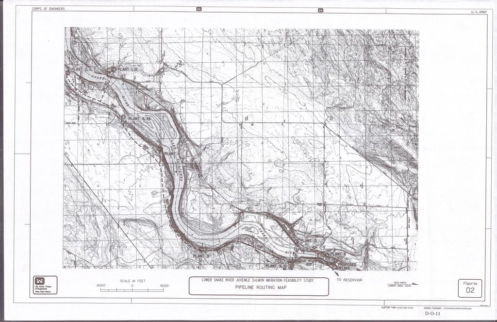
1 Annex O Irrigation Systems Modification Plan Table O1 Figure O1 Figure O2 Pump Station Data Typical Water Intake Pipeline Routing Map H:\WP\1346\Appendices\FEIS\D - Drawdown\CamRdy\App_D.doc
2 Annex O: Irrigation System Modification Plan O.1 General This annex addresses modifications needed to the lower Snake River facilities that withdraw water from the Ice Harbor Reservoir for agricultural uses. Modifications described here are not considered as part of the project implementation costs. The plan and costs were developed for economic evaluations of local, regional, and national impacts. Irrigation water facilities for agricultural use are concentrated at the Ice Harbor Reservoir. Of the 19 listed pumping stations and associated operators, 12 pumping stations are currently using Snake River water for agricultural purposes. Table O1 provides a summary of pumping plants, operators, pumping capacity, and irrigated area and crops. Note that several facilities are joint use facilities where two or more operators use one plant site. The area irrigated by the 12 pumping stations totals approximately 15,000 hectares (37,000 acres) of land. Approximately 11 percent of the irrigated acreage is used for fruit trees, 6 percent for grape vineyards, 23 percent for hybrid poplar and cottonwood harvested for pulp for cardboard manufacture, and 46 percent for annual row crops. Approximately 14 percent of the acreage is undefined. A total of 40 percent of the acreage is used for mature tree-like plants that are not capable of surviving a season without irrigation. The primary assumption on which this irrigation system modification is based is that the current water demand must be met by a replacement system and be operational prior to the initiation of the drawdown of the Ice Harbor Reservoir. The system must function through a full range of river stages without interruption. The design, operation, or scheduled maintenance must address the presence of large quantities of suspended sediment in the water for extended periods of time for several irrigation seasons. O.2 Alternatives O.2.1 Existing Systems There are seven privately-owned irrigation pumping stations on the Ice Harbor Reservoir. These pumping stations range in size from a peak pumping capacity of 0.2 m 3 /s (5.6 cfs) to a peak capacity of 7 m 3 /s (247 cfs). In general, the existing pumping stations draw water through intake screens in the pool and pump the water uphill to corresponding distribution systems. The majority of the pumps are vertical type with a few centrifugal pumps. Without the pool of water created by the Ice Harbor Dam, the intakes to these pumping stations would be completely out of the water and would be unable to lift water from the new, lower water surface. O.2.2 Discussion of Alternatives This study team considered several alternative means of providing water to the irrigators. Those alternatives included: 1) relocating the pumping stations to the new shoreline, 2) adding booster pumping stations to pump water from the new shoreline to the existing pumping stations, and 3) building a single large pumping station and distribution system that would serve all of the irrigators. D-O-1
3 Table O1. Pump Station Data Facility No. Location Feature Existing Pump Data Pumps IH1 IH2 IH3 IH4 IH4A IH5 IH6 IH7 IH8 IH9 IH10 IH11 IH12 NWNE S18, T9N, R32E RM 12 NENE S19, T9N., R32E, RM 11.3 SWSW S36, T10N, R32E, RM 16.9 SESE S8, T9N., R32E RM 13 SESE S8, T9N., R32E RM 13 NENE S19, T9N, R32E RM 12 NWNE S9, T9N, R32E RM 14.4 NENE S19, T9N, R32E RM 12 NESE S23, T10N, R32E. RM 19 SESW S24, T10N, R32E RM SESW S24, T10N, R32E RM SESW S13, T10N, R32E RM 20.4 NWNE S18, T9N, R32E RM 12 Type Total Hp # Pumps Existing Head Peak Req. 2, ,900 Tubine 3, 6 centrifugal 2 4, ,000 13, , ,000 1, , ,000 2, ,000 4, ,000 Same as IH , ,000 3, ,500 included with IH1 IH13 RM 10.3? ,500 IH14 SENW S3 T9N, R32E ,800 RM 15.3 IH15 IH15 IH16 NENE S8, T10N, R33E RM 23.6 NWSE S4, T10N, R32E RM 24.8 NENW S24, T9N, R31E, RM 10.3 Split -case centrifugal Split-case centrifugal , , ,970 Alternatives 1 and 2 Alternatives 1 and 2 were not examined in detail for several reasons. After drawdown, the water surface elevation and water depth would vary considerably for unregulated flow conditions in the river. Water surface fluctuations between the mean low water elevation and the 100-year flood range from 3 meters D-O-2
4 (9 feet) to 5 meters (15 feet). Because of these fluctuations in water surface elevation, it would be reasonable to use submersible inline pumps for this application. Passive intake screens, installed on the pump suction piping to prevent both passage of debris and harm to fish would need to be located properly to maintain adequate submergence during low flow conditions. An air-burst back-flush cleaning system would be needed for each submerged screen. The majority of this stretch of the river has a rather wide, flat bottom with substantial silt, sand, and gravel deposits. It is possible that, as material in the river erodes and deposits, serious problems would occur with this type of pumping arrangement. The river may meander, affecting the availability of water for pumping. Deposited material could reduce intake screen submergence or could cover and plug the screens. Erosion could undermine the pumps, piping, and intake screens, affecting the structural integrity of the system. The submerged equipment would be susceptible to damage due to impact from debris. This type of system, regardless of the sediment concerns, would be difficult to operate and maintain. Finally, in addition to the questionable reliability, installing this type of system prior to or during drawdown would be difficult and costly. Alternative 3 After considering the alternatives, the study team focused on building one large pumping station and distribution system. The team selected this alternative because it avoided many of the problems associated with the other alternatives. In the vicinity of existing pumping plant IH11, the river is narrow and is contained within steep basalt walls. A review of pre-dam river profiles shows the water to be deep in this stretch of the river during minimal flow conditions. This site lends itself well to installation of a large pumping station. Adequate depth is maintained over the pump bowls even at low flows. The rock channel would minimize erosion, and the higher velocities in this narrow stretch would prevent accumulation of silt, sand, and gravel. The steep walls of the channel enable conventional vertical pumps to be used instead of submersibles. Providing one large pumping plant to serve all irrigators also has advantages with respect to implementation. The majority of the work on the pumping plant and pipeline could be accomplished prior to drawdown. Connecting the new pipeline system to existing irrigation plants may be accomplished in the off-season prior to drawdown. Sediment Concerns It is anticipated that the silt and sand that has accumulated in the reservoirs behind the dams would be eroded and entrained by the faster moving river flows during and after drawdown. It may take several years for this material to be depleted. In addition approximately 3 to 4 million cubic yards of sediments are added to the system from the Snake and Clearwater Rivers. This poses a significant problem for all water supplies that rely upon the river as a source. Excessive quantities of silt and sand would cause damage to pumps, valves, sprinklers, and other components. Intakes would have to be kept clean and clear. Sand particles are heavy enough that most can be kept out of well-designed pumping systems. The silt, however, may remain suspended for long periods of time, even if pumped into large settling ponds. Removal of suspended particles from the pumped water supply could be accomplished by flocculents, but a chemical treatment plant to treat up to 19 m 3 /s (680 cfs) would be impractical to construct and operate. The most practical means of handling sand and silt is to use large settling ponds. Settling ponds would help remove sand passed-on from the pumping plant at the river as well as some of the suspended silt. No D-O-3
5 data are available to quantify the expected sediment load in the river. The extent of required settling facilities is pure speculation at this point and will need to be addressed in detail in future design efforts. O.3 Selected Configuration O.3.1 General Discussion The selected primary irrigation system is a pressure supply system that withdraws water from one river location and supplies all the distribution systems. An optional feature is to construct a reservoir for sediment and surge control with a main pumping plant and make appropriate modifications to the river intake plant. The primary irrigation system consists of five main components: 1) a pumping plant at the river, 2) a piping system, 3) connections to existing irrigation systems, 4) secondary pumping plants, and 5) a control system. The plant at the river lifts to the piping system. At plants IH3 and IH6, the new pipeline crosses the path of the existing irrigation pipelines at an elevation considerably higher than and distant from the existing pumping plants. Instead of extending a branch from the new pipeline down to the existing pumping plants and pumping the water back up to the branch elevation, it makes more sense to abandon the existing pumping plant and construct new secondary plants near the intersection between the new and existing pipelines. A control system would be needed to coordinate pumping activities. Float switches would be needed to start and stop the pumps at the river as the water surface in the settling pond fluctuates. Pressure switches or interlocking relays would be needed to coordinate the main pumps with system demand and the start-up or stopping of pumps at the various irrigation plants. The optional reservoir requires the addition of four main components: 1) a large settling reservoir, 2) a main pumping plant, 3) reconfigured pumps at the river intake plant, and 4) additional supply piping to the reservoir and additional discharge piping from the reservoir. The plant at the river would lift the river water up to the settling reservoir while the main pumping plant would pump from the settling pond into the piping system. The pumps in the system must be sized to deliver the quantities of water needed by each irrigator. The size of the motors on the pumps is related to the volume of water being pumped, elevation changes, flow losses in the piping system, and the desired pressure at the ends of the pipe branches. Pipe size can greatly influence flow losses in the system and, thus, the size of the motors needed on the pumps. Large-diameter pipe is desired to reduce motor sizes and power consumption. On the other hand, smaller-diameter piping is desirable to reduce pipe costs for such a long, extensive pipeline. In selecting pipe size and motor size and in determining the number of pumps to use, overall project cost and practicality were considered by thus study team, but only at a cursory level. If the decision is made to drawdown the reservoirs and a pumping system similar to that described below is to be pursued, the cost ramifications should be more carefully reviewed. O.3.2 Primary Irrigation System Primary River Pumping Station Description The intake structure would be divided into five bays or sumps and would have a large horizontal deck upon which the pump motors would be mounted. The peak capacity of the pumping plant is estimated be 7 m 3 /s (850 cfs). This peak capacity is 25 percent greater than the 19 m 3 /s (680 cfs) peak irrigation demand in order to provide additional capacity to compensate for pumps that are out of service. D-O-4
6 Immediately behind the trash racks, bulk-head slots would be placed to allow each bay to be dewatered when needed for maintenance. Behind the bulkhead slots, vertical traveling debris screens would be installed. The screens would have openings no greater than 2 millimeters (0.08 inches), as required to control entrance flow velocities for fish. The river-facing surface of the screen would travel upwards, carrying any debris attached to the screen surface to the top of the structure. A water spray system within the screen assembly would clean debris from the screen near the top of the structure. A wetted debris channel within the structure deck would convey debris washed from the screen back to the river. pump motors would be secured to the deck above each bay, the pump columns extending down into the sump. The pumps would be divided among the five bays. Each bay would have three 1,500- hp pumps and two 600-hp pumps. Valves would be installed on the discharge of each pump to allow the pump to be isolated from the system for maintenance. The valves would be automatically controlled to open slowly after pump start and close slowly prior to pump shutdown in order to control water hammer and surging. Discharge from each pump would manifold to the connection with the main pipeline. A mobile crane could be used to remove and install pump and system components on an asneeded basis. Sand and silt that accumulates in the pump sumps would be conveyed to one end of the sump and pumped out for disposal. Electrical switchgear would be located at deck level. Pumps would be operated in stages as needed to control pressure and flow. Start-up of the private irrigation pumps that are supplied by this pump station would need to be coordinated to keep demand fluctuations at an acceptable level. Secondary Pumping Plants The secondary pumping systems would be comprised of covered slabs with canned vertical pumps. Power supply, switchgear, and control systems would be required. The study team assumed that twelve 1,000-hp pumps would be required for the plant that would replace pump station IH3 and four 400-hp pumps would be required for the plant that would replace pump station IH6. The pump suction piping for both of these plants would be plumbed directly to the new water supply pipe with the discharge plumbed into the existing irrigation piping. Pipeline Description In general, the proposed pipeline would follow the south shore of the Snake River. The study team assumed that epoxy-lined and polyethylene-coated steel pipe, conforming to American Water Works Association (AWWA) C200, would be used with 18-meter (60-foot) pipe lengths and weld bell ends. At the river pumping station, the discharge piping from the pumps would manifold into the main pipeline. For a 2-meters-per-second (m/s) (6-feet-per-second [ft/s]) target flow velocity in the pipe, 4-meter (12- foot) diameter pipe would be needed close to the pumping station. The remainder of the pipeline was sized based upon an 2-m/s (6-ft/s) flow velocity, with pipe size reducing as flow is withdrawn to the various existing pumping plants. Pipe wall thickness was based upon internal pressure and external loading. External loads were calculated assuming the following: 1) the piping would be buried with a cover of 3 feet; HS-20 highway loading might be realized; and pipe bedding and compaction would achieve a soil modulus of at least 7 by 10 5 Pascal (Pa) (1,000 pounds per square inch [psi]. The pipeline from the river would begin at the pump station near river kilometer 32 (river mile 20), proceeding downstream approximately 1,585 meters (5,200 feet) to the branch to IH11. The pipe to IH11 would be 1,067 millimeters (42 inches) in diameter and would cross the river along the river bottom. The D-O-5
7 length of this branch was estimated to be 823 meters (2,700 feet) to cross to Emma Lake and an additional 1,372 meters (4,500 feet) to IH11. The pipe to IH11 would need to be excavated in the river channel and covered with rock. The pipeline serving the remaining stations would begin at 3,048 millimeters (120 inches) in diameter. Near IH9, the pipeline pipe would cross a ravine. This crossing may be achieved by suspending the pipeline above the ravine on piers or excavating and covering the pipe in the ravine bottom. The branch to IH9 is estimated to be 30 meters (100 feet) long and would be 914-millimeter (36-inch) diameter pipe. From the IH9 branch, the main line would reduce to 2,743 millimeters (108 inches) in diameter and continue along the river bank side of the railroad tracks towards IH3, a length of 3,810 meters (12,500 feet). Near river kilometer 28.0 (river mile 17.4) and prior to IH9, the bank of the railroad extends all the way to the river. At this location, complete excavation and burial of the pipe may be impractical. The study team assumed that partial excavation would occur and that cover and rip-rap would be provided along this 305-meter (1,000-foot) stretch of the line. Near river kilometer 27.7 (river mile 17.2), again prior to IH9, the main line would cross beneath the railroad tracks to the south side. The study team assumed that, for this crossing and all subsequent railroad and highway crossings, the main line would pass through a vented casing that extends beyond the limits of the crossing. A 61-meter (200-foot) long, 1,829-millimeter (72-inch) diameter branch would feed water to a secondary pump station for IH3. After the branch to IH3, the main line would reduce to 2,286 millimeters (90 inches) in diameter and extend up the mild slope to the top of the bluff above the river over a length of 4,511 meters (14,800 feet) to the IH6 branch. The 762-millimeter (30-inch) diameter, 123-meter (400-foot) long branch to the IH6 system would feed a secondary pumping plant. After the IH6 branch, the 2,469-m (8,100-foot) main line would remain 2,286 millimeters (90 inches) in diameter and would continue along the bluff, angling down toward the river and the IH4 plant. The 30-m (100-foot) long, 762-millimeter (30-inch) diameter branch to IH4 need not cross under the tracks because the main portion of the IH4 plant is south of the tracks. After branching to IH4, the main line would reduce to 2,134-millimeter (84-inch) diameter pipe and would continue 1,067 meters (3,500 feet) to the IH1/IH12 branch. Shortly after the IH4 branch and prior to the IH1/IH12 branch, the main line would again cross under the railroad tracks. The 1,372-meter (4,500-foot) long, 914-millimeter (36-inch) diameter IH1/IH12 branch would extend across the river bottom and discharge into the north shore bay in which the IH1/IH12 plant is installed. The study team assumed that this bay would be sealed to act as a reservoir for the IH1/IH12 plant, although it may prove to be more cost effective to extend the piping all the way to the pumping plant and manifold the supply directly to the pumps. After the IH1/IH12 branch, the main line would reduce to 1,981 millimeters (78 inches) in diameter and continue 701 meters (2,300 feet) to its termination at the IH2/IH5/IH7 plant. The majority of the IH2/IH5/IH7 branch would parallel existing gravel and paved roadways, having to cross a paved roadway at one location. Buried utilities would likely be encountered along the route of the IH2/IH5/IH7 branch. Pipeline Specials Two of the existing pumping plants, IH6 and IH4, are multi-pump configurations. These plants use small pumps at the river to lift water to main pumping plants that are a short distance further up the shore. The D-O-6
8 piping from the small plant is plumbed directly into the suction piping of the main plant. This type of arrangement is proposed for connecting the new water supply to each of the affected pumping plants, plants IH6 and IH3 excluded. For plant IH4, the small plant at the river would be abandoned and the existing manifold at the main plant would be connected to the new branch pipe. For plants IH11, IH9, IH1/IH12, and IH2/IH5/IH7, manifolds need to be constructed and installed to connect each pump to the branch piping. The study team assumed that the manifolds would be simple horizontal pipes with vertical branches extending up to and connecting with the bottom of each pump. Some structural modifications would be needed for the plants that need manifolds. Typical structural modifications would include boring through concrete walls in the existing sumps and providing supports for the manifolds. In the branch piping near each existing plant and each secondary, an isolation valve would be required to allow the plant to be isolated from the supply system as needed for plant maintenance. The valves would need to be the slow opening and closing type to prevent surging. The study team assumed that manual valve operators would be provided. The team also assumed that a flow meter would be needed in each pipe branch in order to monitor water consumption. At each branch pipe and at each significant change in direction, the piping would need to be constrained against thrust. The team assumed that concrete thrust blocks would be used to accomplish this. At the new pumping plant near river kilometer 32 (river mile 20), the main line would need to be constrained along the entire length of the intake structure due to the thrust generated by flow from the pump manifolds. At all high points, large air release/vacuum valves (ARVs) would be required. The ARVs need to be sized to suit the pipe and flow. It is anticipated that at least six locations would require ARVs. At all low points, drain valves and drain discharge piping would be required to allow the pipeline to be drained. It is anticipated that at least six 610-millimeter (24-inch) diameter drain valves and piping and at least four 305-millimeter (12-inch) diameter drain valves and piping would be required. O.3.3 Optional Reservoir The sediment concentration in the river is difficult to determine. The ability of the irrigation system to handle high volumes of sediment in the supply water is questionable. Ideally, a holding pond sized to detain the water for a sufficient time to allow settling of suspended solids is desired. A reservoir to provide a significant detention time for peak flows of 19 m 3 /s (680 cfs) would be sizeable. The study team estimated that a reservoir of approximately 396 m 3 (14,000 acre-feet) would be required. This assumes an active storage volume of 50 percent and a detention time of 5 days. More detailed evaluation of sediment characteristics may indicate that more advanced water treatment is necessary to remove sediments from the water. This study team assumed that the area just to the east of the river intake would be the site of the proposed reservoir. The reservoir would be excavated and enclosed using earthen dikes. The reservoir area would be lined with a geomembrane liner to prevent excessive seepage of the stored water. The liner would be subsequently covered with a protective layer of fine-grained material. More detailed evaluations and reconfiguring of the intake and irrigation system may allow advantageous use of existing topographic features to better site a reservoir. In order to incorporate an in-line reservoir, the river intake would be reconfigured so that each bay would have three 2,500-hp pumps. This horsepower is based upon the settling reservoir having a mean water D-O-7
9 surface elevation of meters (700 feet). At the river pumping station, the discharge piping from the pumps would manifold into the main pipeline that feeds the settling reservoir. The pipeline from the river begins at the pump station near river kilometer 32 (river mile 20), angling up the hill approximately 671 meters (2,200 feet) and discharging into the settling reservoir above. To provide a range of flows between partial and full irrigation demand, numerous pumps at the main pumping station would be required. The study team selected an arrangement of hp pumps and hp pumps. For 18 meters (60 feet) of head, the 250-hp pumps would each provide 51 m 3 /m (13,440 gpm), and the 150-hp pumps would each provide 25 m 3 /m (6,720 gpm). The head required of these pumps is small because the settling pond elevation is equivalent to the highest anticipated elevation of the pipeline. The 18 meters (60 feet) of design head assures at least 6 meters (20 feet) of surplus head that exist along the entire length of the pipeline. The study team assumed that canned vertical pumps would be used in order to take advantage of the greater efficiencies possible with this type of pump. The pumps would be supported from a slab with water reaching the pump intakes through buried piping that extends out into the settling pond. It should also be noted that the use of variable frequency driven pumps to reduce the number of pumps needed to cover a broad range of demand is another alternative that could be very advantageous and should be examined in more detail if the drawdown proceeds. Debris would inevitably be encountered in the settling reservoir. If the debris were sucked into the pumps, damage could occur. Therefore, the study team assumed that intake screens would be required. Manual cleaning of the intake screens should suffice since debris loads should not be heavy. Power supply, switchgear, and control systems would be required. A roof with removable sections for pump access should be provided to shelter the pumps from the elements and allow pump maintenance. A single pipeline would discharge water from the settling pond to the branch near plant IH11. The 1,067-millimeter (42-inch) line would then branch to IH11 across the river, and the mainline would continue on to serve the remaining plants O.3.4 Maintenance Requirements The extent of increased maintenance activity to treat sediment related problems is not known. Certainly replacement of the wear parts of the pumps, valves, sprinklers, and filters would initially be at a high frequency. Even in later years a higher frequency of parts replacement could be expected with the river in its natural state. O.4 Schedule Construction activities for this system must be completed by January of the year in which drawdown occurs. Each irrigator must start the irrigation season on the new system. Drawdown begins in early August of that year, the period of peak water demand. In order of accomplish this, construction of the river intake, the pipeline, and the optional reservoir must commence 24 to 36 months in advance of the January completion date. D-O-8
10
11
Annex Q Potlatch Corporation Water Intake Modification Plan
 Annex Q Potlatch Corporation Water Intake Modification Plan Figure Q1 Figure Q2 Site Plans Johnson Screen Installations H:\WP\1346\Appendices\FEIS\D - Drawdown\CamRdy\App_D.doc Annex Q: Potlatch Corporation
Annex S Potlatch Corporation Effluent Diffuser Modification Plan
 Annex S Potlatch Corporation Effluent Diffuser Modification Plan Figure S1 Figure S2 Site Plan Effluent Pipeline Trench H:\WP\1346\Appendices\FEIS\D - Drawdown\CamRdy\App_D.doc Annex S: Potlatch Corporation
MEMORANDUM. The general findings of the assessment are as follows:
 November 28, 2006 MEMORANDUM Project No.: 030009-002-01 To: From: Re: WRIA 31 Planning Unit Steve Germiat, LHG, CGWP, and Timothy J. Flynn, LHG, CWGP Evaluation of Winterizing Existing River Pump/Conveyance
Annex I Lyons Ferry Hatchery Modification Plan
 Annex I Lyons Ferry Hatchery Modification Plan Table I1 Figure I1 Figure I2 Figure I3 Figure I4 Figure I5 Well Characteristics Lyons Ferry Hatchery Vicinity Map Lyons Ferry Hatchery Site Plan Water Supply
Annex V Concrete Structures Removal Plan
 Appendix D Annex V Concrete Structures Removal Plan Figure V1 Lower Granite Sequences of Concrete Removal and Cofferdam Figure V2 Little Goose Sequence of Concrete Removal and Cofferdam Figure V3 Lower
Lyon Creek Cedar Way Stormwater Detention Dam Operation and Maintenance Manual
 Lyon Creek Cedar Way Stormwater Detention Dam Operation and Maintenance Manual Prepared by: Mike Shaw Stormwater Program Manager City of Mountlake Terrace January 2010 Section I General Information This
CONSTRUCTION PLAN CHECKLIST
 CONSTRUCTION PLAN CHECKLIST The design engineer is responsible for ensuring that plans submitted for city review are in accordance with this checklist. It is requested that the executed checklist be submitted
Created by Simpo PDF Creator Pro (unregistered version) Asst.Prof.Dr. Jaafar S. Maatooq
 Asst.Prof.Dr. Jaafar S. Maatooq") Lect.No.9 2 nd Semester Barrages, Regulators, Dams 1 of 15 In order to harness the water potential of a river optimally, it is necessary to construct two types of hydraulic structures, as shown in Figure
Lect.No.9 2 nd Semester Barrages, Regulators, Dams 1 of 15 In order to harness the water potential of a river optimally, it is necessary to construct two types of hydraulic structures, as shown in Figure
SECTION WASTEWATER FORCE MAINS
 SECTION 02732 WASTEWATER FORCE MAINS PART 1 GENERAL 1.01 GENERAL: A. This section includes the general requirements for design and installation of force main systems serving wastewater lift stations. B.
Flood Hazard Assessment Report Falls Gulch, Larimer County, Colorado January 16, 2013
 United States Department of Agriculture Natural Resources Conservation Service Denver Federal Center Building 56, Room 2604 P.O. Box 25426 Denver, CO 80225 720-544-2818-OFFICE alton.albin@co.usda.gov Flood
COFFERDAM (no.) CODE 803
 CODE 803") ILLINOIS URBAN MANUAL PRACTICE STANDARD COFFERDAM (no.) CODE 803 Source: Kane-DuPage Soil and Water Conservation District DEFINITION A cofferdam is a temporary structure within a waterway or body of water
ILLINOIS URBAN MANUAL PRACTICE STANDARD COFFERDAM (no.) CODE 803 Source: Kane-DuPage Soil and Water Conservation District DEFINITION A cofferdam is a temporary structure within a waterway or body of water
SECTION WASTEWATER FORCE MAINS
 SECTION 02732 WASTEWATER FORCE MAINS PART - GENERAL 1.01 GENERAL: A. This section includes the general requirements for design and installation of force main systems serving wastewater lift stations. B.
TEMPORARY SEDIMENT TRAP CODE
 ILLINOIS URBAN MANUAL PRACTICE STANDARD TEMPORARY SEDIMENT TRAP CODE 960 Source: DEFINITION A small temporary stormwater storage structure designed to trap sediment. PURPOSE The purpose of this practice
Types of Hydropower Facilities
 Types of Hydropower Facilities 1 Impoundment Hydropower- uses a dam to store water. Water may be released either to meet changing electricity needs or to maintain a constant water level. 2 Run-of-River
PART 1 GENERAL REQUIREMENTS
 PART 1 GENERAL REQUIREMENTS Contract Closeout Plan 110 Arrow diagram for project close-out...3 Erosion Control 121 Straw bale barrier... 5 122 Silt fence... 7 123 Diversion dike... 9 124 Inlet protection...
Energy Requirements for Drip Irrigation of Tomatoes in North Florida 1
 BUL289 Energy Requirements for Drip Irrigation of Tomatoes in North Florida 1 A.G. Smajstrla, B.F. Castro and G.A. Clark 2 INTRODUCTION The energy required to pump irrigation water for crop production
Ducks Unlimited M&T Ranch / Llano Seco Intake Project Final Alternatives
 Ducks Unlimited M&T Ranch / Llano Seco Intake Project Final Alternatives M&T Ranch / Llano Seco Intake Project Final Alternatives Draft Engineering Analysis Technical Memorandum Ducks Unlimited September,
Ag Water Energy Center at Fresno State
 Water Use Efficiency for Grapes and Almonds Presented by the (CIT) California State University, Fresno Ag Water Energy Center at Fresno State The Designers and Managers of the Program: Water and Energy
Valve Nest Filter with Time Clock Control Installation and Operation Manual
 Valve Nest Filter with Time Clock Control Installation and Operation Manual Effective 5/24/12 Effective 5/24/12 Table of Contents Operating Data. 1 Pre-Installation Data... 2 Filter Parameters Installation
ITEM 481 MONOLITHIC REINFORCED CONCRETE BOX SEWERS
 AFTER FEBRUARY 1, 2011 ITEM 481 MONOLITHIC REINFORCED CONCRETE BOX SEWERS 481.1 Description. This specification shall govern for the construction of monolithic, reinforced concrete box sewers of the size,
Irrigation System. BWCDD Zanjero Training 2/13/2008
 Irrigation System BWCDD Zanjero Training Session #7 2/13/2008 Irrigation System The (main) intake structure t directs water from the source of supply, such as a reservoir or a river, into the irrigation
ITEM 432 TUNNEL CONSTRUCTION
 AFTER MARCH 1, 2012 ITEM 432 TUNNEL CONSTRUCTION 432.1 Description. This Item shall govern for tunnel lines under railroads, state highways, and concrete paved streets or other obstructions indicated.
Bowling Green, Kentucky Stormwater Best Management Practices (BMPs) Sediment Management Practices (SMPs) Activity: Temporary Inlet Protection (TIP)
 Sediment Management Practices (SMPs) Activity: Temporary Inlet Protection (TIP)") Bowling Green, Kentucky Stormwater Best Management Practices (BMPs) Sediment Management Practices (SMPs) Activity: Temporary Inlet Protection (TIP) SMP-11 PLANNING CONSIDERATIONS: Design Life: 1 yr Acreage
Bowling Green, Kentucky Stormwater Best Management Practices (BMPs) Sediment Management Practices (SMPs) Activity: Temporary Inlet Protection (TIP) SMP-11 PLANNING CONSIDERATIONS: Design Life: 1 yr Acreage
Appendix J Effluent Pump Station
 Appendix J Effluent Pump Station TECHNICAL MEMORANDUM Salmon Creek Treatment Plant Effluent Pump Station Hydraulics and Phasing Analysis for the Phase 5A Project Columbia River Outfall and Effluent Pipeline
SPECIFICATIONS FOR STRUCTURAL EXCAVATION
 SPECIFICATIONS FOR STRUCTURAL EXCAVATION 1.0 DESCRIPTION The Work shall consist of:.1 Excavation and removal of material for the placement of foundations, substructure units, approach slabs, transition
Typical Local Erosion Control Requirements (Storm Water Management Authority, Inc.)
") Module 2: Selection of Controls and Site Planning for Construction Site Erosion Prevention Robert Pitt Department of Civil, Construction, and Environmental Engineering University of Alabama Tuscaloosa,
Module 2: Selection of Controls and Site Planning for Construction Site Erosion Prevention Robert Pitt Department of Civil, Construction, and Environmental Engineering University of Alabama Tuscaloosa,
SECTION TRENCHING, BACKFILLING, COMPACTION AND GENERAL GRADING
 PART 1 GENERAL SECTION 02221 TRENCHING, BACKFILLING, COMPACTION AND GENERAL GRADING 1.01 SECTION INCLUDES A. Excavation, dewatering and backfilling with compaction of trenches for pipes, conduits, channels
5555ter supply the Eugene Mill Race is a costly task that may have alternatives not explored by its
 Scdr45555555555555555555555555555555555555555555555555555555555555555555555555555555 5555ter supply the Eugene Mill Race is a costly task that may have alternatives not explored by its proprietor. The
Annex A Turbine Passage Modification Plan
 Appendix D Annex A Turbine Passage Modification Plan Table A1 Model Turbine Performance Table A2 Model Turbine Performance Table A3 Model Turbine Performance Table A4 Model Turbine Performance Table A5
Block and gravel filters can be used where velocities are higher. Reduces the amount of sediment leaving the site.
 INLET PROTECTION From Massachusetts Erosion and Sediment Control Guidelines for Urban and Suburban Areas http://www.state.ma.us/dep/brp/stormwtr/files/esfull.pdf Definition: A sediment filter or an excavated
SECTION GRAVEL PACKED WATER WELL
 SECTION 02520 GRAVEL PACKED WATER WELL PART 1 GENERAL 1.01 SECTION INCLUDES A. Gravel packed water well includes drilling, installing, cleaning, developing, testing, videoing, abandoning, and site clean
Best Practices for Building High-Performance Resource Roads. Road Drainage. Developed by: The Roads and Infrastructure Group
 Best Practices for Building High-Performance Resource Roads Road Drainage Developed by: The Roads and Infrastructure Group THIS GUIDE IS INTENDED FOR EQUIPMENT OPERATORS CONSTRUCTION CONTRACTORS FIELD
APPENDIX A - SURFACE OUTLET AND BAFFLE SEDIMENT BASINS
 APPENDIX A - SURFACE OUTLET AND BAFFLE SEDIMENT BASINS AND MULTIPURPOSE BASINS This Appendix contains requirements for the design, materials, equipment, and construction of temporary Surface Outlet and
Misan University - College of Engineering Civil Engineering Department
 CHAPTER 2 Soil and Excavations Soil investigation including two phases: surface investigation and subsurface investigation Surface investigation involves making a preliminary judgment about the site s
STORM DRAINAGE DESIGN MANUAL
 Appendix I STORM DRAINAGE DESIGN MANUAL by: SUNGATE DESIGN GROUP, P.A. GEN ERAL DESIGN STAN DARDS AN D POLICIES 1. STREET AND LOCAL DRAINAGE Discharge estimates for specified design storms shall be calculated
Screening, Definition: The unit involved is called a screen.
 Screening, Definition: Screening is a unit operation that separates materials in and/or on water (found in different sizes) from water and from entering water treatment facilities and mains. The unit involved
SECTION TRENCHING & BACKFILLING
 SECTION 02225 - TRENCHING & BACKFILLING 1.0 GENERAL 1.1 Work included in this Section includes trenching and backfilling for underground pipelines and related structures only. 1.2 Reference Specifications
APPENDIX A. Hydraulic Investigations: Cascade Mall at Burlington
 APPENDIX A m SUMMARY REPORT FOR E.I.S. Hydraulic Investigations: Cascade Mall at Burlington July 12, 1982 John E. Norman, P.E. 14779 Northeast 32nd, #A201 Bellevue, WA 98007 (206) 882-1767 92 General A
Inlet Protection. Fe= (Depends on soil type)
") 3.4 DESIGN CRITERIA: KEY CONSIDERATIONS Evaluate drainage patterns to ensure inlet protection will not cause flooding of roadway, property or structures Never block entire inlet opening Size according
3.4 DESIGN CRITERIA: KEY CONSIDERATIONS Evaluate drainage patterns to ensure inlet protection will not cause flooding of roadway, property or structures Never block entire inlet opening Size according
SECTION TRENCHING
 SECTION 31 23 17 TRENCHING PART 1 GENERAL 1.1 SUMMARY A. Section Includes: 1. Excavating trenches for utilities and utility structures. 2. Bedding. 3. Backfilling and compacting to subgrade elevations.
StaticOrb Screens. Water and Effluent Treatment
 Water and Effluent Treatment StaticOrb Screens Screen Services Specialty screens and equipment for industrial, petrochemical, mining, and water treatment applications Phone (780) 460-8043 North America
Water Control Structures Selected Design Guidelines Alberta Environment Page 14-1
 Alberta Environment Page 14-1 14.0 LOW LEVEL OUTLET WORKS 14.1 General In general, a low level outlet structure can be used to provide one or more of the following functions: Supply adequate water to meet
Products II 1 VERTICAL LINE SHAFT PRODUCT AND OIL LUBRICATED PUMPS II 2 SUBMERSIBLE PUMPS II 3 MIX FLOW PRODUCT AND OIL LUBRICATED PUMPS
 II Products II 1 VERTICAL LINE SHAFT PRODUCT AND OIL LUBRICATED PUMPS PAGE II-2 II 2 SUBMERSIBLE PUMPS PAGE II-4 II 3 MIX FLOW PRODUCT AND OIL LUBRICATED PUMPS PAGE II-5 II 4 AXIAL FLOW PRODUCT AND OIL
Upper Mississippi River Basin Environmental Management Program Workshop
 Presentation to the Upper Mississippi River Basin Environmental Management Program Workshop by Kara Mitvalsky Environmental Engineer US Army Corps of Engineers, Rock Island District August 18, 2005 Engineering
4. Ponds and infiltration BMPs can achieve 60 to 100% removal efficiencies for sediment.
 Landscape BMPs For the purposes of this project, preventive measures have been categorized into two categories: landscape BMPs and source prevention BMPs. Landscape BMPs includes both vegetative practices
DRAFT SEDIMENT and EROSION CONTROL PLAN. BLUE LAKE HYDROELECTRIC PROJECT (FERC No. 2230) EXPANSION. Prepared by:
 EXPANSION. Prepared by:") DRAFT SEDIMENT and EROSION CONTROL PLAN BLUE LAKE HYDROELECTRIC PROJECT (FERC No. 2230) EXPANSION Prepared by: Electric Department 1.0 INTRODUCTION The Electric Department ( City ) is in the process of
DRAFT SEDIMENT and EROSION CONTROL PLAN BLUE LAKE HYDROELECTRIC PROJECT (FERC No. 2230) EXPANSION Prepared by: Electric Department 1.0 INTRODUCTION The Electric Department ( City ) is in the process of
F. Provide at least 2 feet of vertical separation between a water line and any utility or stormdrain crossing it.
 Section 3 F. Provide at least 2 feet of vertical separation between a water line and any utility or stormdrain crossing it. 3.8 Highway Crossings The design engineer shall, prior to the design of any highway
SE-6 GRAVEL BAG BERM. Objectives. Potential Alternatives
 Objectives Erosion Control - EC Sediment Control - SE Tracking Control - TC Wind Erosion Control - WE Non-Storm Water Management - NS Materials and Waste Management - WM DESCRIPTION AND PURPOSE A gravel
Case Study 12. Grubbs Concrete Slab Vented Ford
 Appendix A Case Study Case Study. Grubbs Concrete Slab Vented Ford Location North central California. Plumas National Forest. Mount Hough Ranger District. Grizzly Creek. 3 miles west of Bucks Lake, CA.
Tips with Creation of your Erosion and Sediment Control Plan
 Tips with Creation of your Erosion and Sediment Control Plan By Chris Droste, CESCO Senior Erosion Control Specialist Westmoreland Conservation District Forming Your Narrative Use the DEP checklist. Page
204 - EXCAVATION AND BACKFILL FOR STRUCTURES SECTION 204 EXCAVATION AND BACKFILL FOR STRUCTURES. Granular Backfill (Wingwalls) (Set Price)
 (Set Price)") SECTION 204 EXCAVATION AND BACKFILL FOR STRUCTURES 204.1 DESCRIPTION Excavate for the structures as shown in the Contract Documents. Unless specified otherwise, backfill the completed structures to the
SECTION 204 EXCAVATION AND BACKFILL FOR STRUCTURES 204.1 DESCRIPTION Excavate for the structures as shown in the Contract Documents. Unless specified otherwise, backfill the completed structures to the
IN-STREAM ISOLATION METHODS: Techniques, Tips and Lessons Learned
 IN-STREAM ISOLATION METHODS: Techniques, Tips and Lessons Learned Presented by Moranne McDonnell, B.E.S., C.E.T., CISEC Associate Director, Engineering Projects TRCA March 23, 2017 TRCA AT A GLANCE One
SECTION 32 EXCAVATION, BACKFILL, COMPACTION AND GRADING
 32.1 GENERAL SECTION 32 EXCAVATION, BACKFILL, COMPACTION AND GRADING This Section covers excavation, backfill, fill and grading associated with utility trench and structural construction. All such WORK
EROSION CONTROL GENERAL NOTES EC JAN 2017 C.B.
 EROSION CONTROL GENERAL NOTES EC - 000 EROSION CONTROL GENERAL NOTES EC - 001 INSTALL TEMPORARY DRIVEWAY CULVERT IF THERE IS A ROADSIDE DITCH PRESENT EXISTING PAVEMENT OR APPROVED ACCESS POINT OR AS PRACTICABLE
Suggested Stormwater Management Practices For Individual House Lots
 Suggested Stormwater Management Practices For Individual House Lots These practices are necessary to satisfy the water quantity and water quality criteria of the Rappahannock Stormwater Ordinance. These
204 - EXCAVATION AND BACKFILL FOR STRUCTURES SECTION 204 EXCAVATION AND BACKFILL FOR STRUCTURES
 SECTION 204 EXCAVATION AND BACKFILL FOR STRUCTURES 204.1 DESCRIPTION Excavate for the structures as shown in the Contract Documents. Unless specified otherwise, backfill the completed structures to the
SECTION 820 PUMP STATION DEMOLITION AND SITE RESTORATION
 820-1 SCOPE OF WORK: SECTION 820 PUMP STATION DEMOLITION AND SITE RESTORATION a. Furnish all labor, materials, equipment, and incidentals required for demolition and/or removal and disposal of existing
Lagoon Pumping and Irrigating Equipment
 University of Missouri Extension G117, Reviewed October 1993 Lagoon Pumping and Irrigating Equipment Charles D. Fulhage Department of Agricultural Engineering Lagoons are an important part of many Missouri
Peerless Pump Company Handbook of Engineering Data
 Peerless Pump Company Handbook of Engineering Data Brochure EM77 DEFINITION OF PUMP TERMS A.1 A line shaft vertical turbine pump is a vertical-shaft centrifugal or mixed-flow pump with rotating impeller
D EROSION AND SEDIMENT CONTROL. Table of Contents
 Table of Contents D1. GENERAL... 1 D2. OBJECTIVE... 1 D3. REFERENCE MATERIAL... 1 D4. REGULATORY REQUIREMENTS... 1 D5. EROSION AND SEDIMENT CONTROL (ESC) PLANS... 2 D5.1 Goals and Objectives:... 2 D5.2
4. FISH PASSAGE CONCEPTS
 Feasibility Study for Restoration of Titlow Lagoon Fish Passage South Puget Sound Salmon Enhancement Group 4. FISH PASSAGE CONCEPTS Fish passage could be improved by rehabilitating the existing fish passage,
Section 7 Design Criteria Irrigation and Drainage Facilities
 Section 7 Design Criteria Irrigation and Drainage Facilities 7.1 Background The Irrigation and Drainage system is comprised of the Coachella Branch of the All-American Canal (Coachella Canal), Protective
Read Only Copy Not For Distribution. Chapter 17. Private Potable Water Supply Systems 17.1 GENERAL REGULATIONS 17.2 QUANTITY OF WATER REQUIRED
 Chapter 17 Private Potable Water Supply Systems 17.1 GENERAL REGULATIONS 17.1.1 Applicability The regulations in this chapter apply to any private potable water supply system where plumbing fixtures are
1. Overview 2 2. Definitions 2 3. Laboratory Testing Criteria 2. A. Laboratory Qualifications 2. B. Analysis of TSS Samples 2. C.
 New Jersey Department of Environmental Protection Laboratory Protocol to Assess Total Suspended Solids Removal by a Hydrodynamic Sedimentation Manufactured Treatment Device January 25, 2013 Contents 1.
SECTION IRRIGATION WATER WELL
 PART 1 GENERAL 1.1 SECTION INCLUDES SECTION 33 21 16 IRRIGATION WATER WELL A. The work shall consist of furnishing all labor, material, equipment, and services necessary for the drilling of irrigation
Greenfield Pond B Rehabilitation
 Preliminary Investigation Report Centennial, Colorado November 15, 2011 Prepared for: Liverpool Metropolitan District Prepared by: Stantec Consulting Services, Inc. Table of Contents Executive Summary...
B. Borrow: Satisfactory soil imported from off-site for use as fill or backfill.
 SECTION 312000- EARTHWORK PART 1 - GENERAL 1.1 RELATED DOCUMENTS Drawings and general provisions of the Contract, including General and Special Conditions, apply to this Section. 1.2 SUMMARY This Section
Dry structural excavation is usually done with front-end loaders, bulldozers or backhoes.
 1.1 Excavation - General Excavation is the removal of all material (including ice, water, etc.) required for the construction of foundations or substructures as indicated on the drawings or as determined
SECTION IRRIGATION WATER WELL
 PART 1 GENERAL 1.1 SECTION INCLUDES: SECTION 02670 IRRIGATION WATER WELL A. The work shall consist of furnishing all labor, material, equipment and services necessary for the drilling of irrigation water
APPENDIX C INLETS. The application and types of storm drainage inlets are presented in detail in this Appendix.
 Storm Drainage 13-C-1 APPENDIX C INLETS 1.0 Introduction The application and types of storm drainage inlets are presented in detail in this Appendix. 2.0 Inlet Locations Inlets are required at locations
Pumped Outlets for Drainage Systems
 ' OCT,,,80 t!) _ jilibrary (446: L UN I VERSTP 4;4 Pumped Outlets for Drainage Systems Special Report 601 September 1980 Oregon State University Extension Service Pumped Outlets for Drainage Systems by
Feasibility Study for Groundwater Availability for Spring Creek Creation at Squalicum Creek Park
 Feasibility Study for Groundwater Availability for Spring Creek Creation at Squalicum Creek Park Prepared for: City of Bellingham Public Works Department Environmental Resource Division 210 Lottie St.
Surface Water Diversions and Fish Protection
 Surface Water Diversions and Fish Protection The Need Taking Water Out of Its Natural Location The Impact Annika W. Walters, Damon M. Holzer, James R. Faulkner, Charles D. Warren, Patrick D. Murphy & Michelle
SECTION 4 - DESIGN STANDARDS FOR WATER DISTRIBUTION FACILITIES
 SECTION 4 - DESIGN STANDARDS FOR WATER DISTRIBUTION FACILITIES 4.1 GENERAL REQUIREMENTS 4.1.1 Water and fire protection distribution facilities are to be provided solely for the purpose of supplying potable
METROPOLITAN UTILITIES DISTRICT No Page: 1 of 10
 Page: 1 of 10 A. GENERAL Erosion control measures such as silt fence, inlet filters and soil stabilization blankets and matting, incorporated into underground pipeline construction projects, help prevent
WEST POINT PERTINENT DATA. GENERAL Location (damsite) Troup County GA, Chambers County AL, miles above mouth of Chattahoochee River
 Troup County GA, Chambers County AL, miles above mouth of Chattahoochee River") WEST POINT PERTINENT DATA GENERAL Location (damsite) Troup County GA, Chambers County AL, miles above mouth of Chattahoochee River 201.4 Drainage area, Buford Dam to West Point Dam, square miles 2,406
WEST POINT PERTINENT DATA GENERAL Location (damsite) Troup County GA, Chambers County AL, miles above mouth of Chattahoochee River 201.4 Drainage area, Buford Dam to West Point Dam, square miles 2,406
CHAPTER 5 WELL CONSTRUCTION
 CHAPTER 5 WELL CONSTRUCTION Wells Shallow ( < 15 meters) Deep ( > 15 meters) Shallow Wells Include Dug wells Kanats Vertical wells Horizontal wells They are drilled by: digging, boring, driving, and jetting
Chapter 5.5 Inlets, Outlets, and Flow Control
 Chapter 5.5 Inlets, Outlets, and Flow Control There are common structural elements of SCMs that are designed to safely route water. Engineered flow control devices are used to effectively route water at
BAYFRONT CANAL AND ATHERTON CHANNEL PROJECT DESCRIPTION
 APPENDIX I BAYFRONT CANAL AND ATHERTON CHANNEL PROJECT DESCRIPTION South Bay Salt Pond Restoration Project Phase 2 July 2015 Draft Environmental Impact Statement/Report 2185 N. California Blvd., Suite
Patterson Irrigation District Policy Regarding Urban Developments and Encroachments
 Patterson Irrigation District Policy Regarding Urban Developments and Encroachments The purpose of this policy is to set reasonable requirements for new developments impacting DISTRICT s mission, facilities
Suitable Applications Where concentrated flow of surface runoff must be conveyed down a slope in order to prevent erosion.
 Categories EC Erosion Control SE Sediment Control TC Tracking Control WE Wind Erosion Control Non-Stormwater NS Management Control Waste Management and WM Materials Pollution Control Legend: Primary Objective
SEWER SYSTEM DESIGN GUIDELINES
 SEWER SYSTEM DESIGN GUIDELINES PART 1 GENERAL 1.1 GENERAL GUIDELINES A. The following sewer system design guidelines are based on Federal, State and Local health requirements, and the Berkeley County Water
Chapter 6 Sand Filtration Treatment Facilities
 Sand Filtration Treatment Facilities 6.1 Purpose This chapter presents criteria for the design, construction and maintenance of runoff treatment sand filters. Treatment sand filters are used to collect,
Making the Right Filter Decisions for Landscape Irrigation
 Making the Right Filter Decisions for Landscape Irrigation Reid Garner, CLIA, CID LAKOS Separators and Filtration Solutions, rgarner@lakos.com Abstract. In today s rapidly changing landscape irrigation
BIG HORN BASIN IRRIGATION WATER MANAGEMENT P ROGRAM
 BIG HORN BASIN IRRIGATION WATER MANAGEMENT P ROGRAM Lateral Move Sprinkler System B I G H O R N B A S I N I R R I G A T I O N W A T E R M A N A G E M E N T P R O G R A M Looking at a New System: The Systems
Managing furrow irrigation
 Section K Managing furrow irrigation The goal of every surface irrigator should be to apply the right amount of water as uniformly as possible to meet the crop needs and minimize leaching of nitrogen from
California Groundwater Association An NGWA Affiliate State 700 R Street Suite 200 Sacramento, CA
 California Groundwater Association An NGWA Affiliate State 700 R Street Suite 200 Sacramento, CA 95811 cga@groundh2o.org 916-231-2134 CGA STANDARD PRACTICE SERIES ARTICLE 550 MANAGEMENT OF SURFACE ARTESIAN
Environmental Engineering-I
 Environmental Engineering-I Prof. Dr. Muhammad Zulfiqar Ali Khan Engr. Muhammad Aboubakar Farooq Department of Civil Engineering The University of Lahore 1 Sources of Water Rain Water Surface Water Ground
Submersible Axial Flow Propeller Pumps
 Submersible Axial Flow Propeller Pumps water wastewater flood control EBARA Fluid Handling an EBARA International Corporation company Features Watertight cable entry system prevents capillary action and
SECTION SOILS REPORT
 SECTION 02300 SOILS REPORT 1. GENERAL: 1.1 All work included under this heading shall be subject to the General Conditions of the entire operation. This Contractor is required to refer especially thereto.
Shelbyville, Kentucky Stormwater Best Management Practices (BMPs) Stormwater Pollution Treatment Practices (Structural) DRAFT
 Stormwater Pollution Treatment Practices (Structural) DRAFT") Shelbyville, Kentucky Stormwater Best Management Practices (BMPs) Stormwater Pollution Treatment Practices (Structural) Activity: Infiltration Systems PLANNING CONSIDERATIONS: Design Life: Short IS Acreage
Shelbyville, Kentucky Stormwater Best Management Practices (BMPs) Stormwater Pollution Treatment Practices (Structural) Activity: Infiltration Systems PLANNING CONSIDERATIONS: Design Life: Short IS Acreage
CENTRALIZED BMPS TYPICALLY PUBLICLY OWNED & MAINTAINED BMPS, TREATING A LARGE (>20 ACRES) URBAN DRAINAGE WITH MULTIPLE LAND
 URBAN DRAINAGE WITH MULTIPLE LAND") BMP RAM BMP Type Definitions 1 CENTRALIZED BMPS TYPICALLY PUBLICLY OWNED & MAINTAINED BMPS, TREATING A LARGE (>20 ACRES) URBAN DRAINAGE WITH MULTIPLE LAND USES AND OWNERSHIP STRUCTURAL BMP TYPE OTHER NAMES
BMP RAM BMP Type Definitions 1 CENTRALIZED BMPS TYPICALLY PUBLICLY OWNED & MAINTAINED BMPS, TREATING A LARGE (>20 ACRES) URBAN DRAINAGE WITH MULTIPLE LAND USES AND OWNERSHIP STRUCTURAL BMP TYPE OTHER NAMES
Stormwater Local Design Manual For Houston County, Georgia
 Stormwater Local Design Manual For Houston County, Georgia Adopted November 15, 2005 TABLE OF CONTENTS 1. FORWARD... 1 2. GENERAL LEVEL OF SERVICE STANDARDS... 2 2.1. DETENTION REQUIREMENTS... 2 2.1.1.
Education. V. Know How to Maintain an Efficient Pump. Pump Efficiency Tests. What is a Pump Test? Who Does the Pump Testing?
 V. Know How to Maintain an Efficient Pump There are at least four important aspects of maintaining an efficient pumping plant: 1. Initial specification and installation of the pumping plant. 2. Ensuring
SECTION EROSION CONTROLS
 SECTION 31 25 13 EROSION CONTROLS PART 1 GENERAL 1.1 SUMMARY A. Section Includes installing, maintaining and removing: 1. Silt Fence. 2. Temporary Construction Entrances. 3. Diversion Channels. 4. Sediment
storage There are three basic systems for storing liquid SYSTEM DESCRIPTIONS
 There are three basic systems for storing liquid manure: formed tanks, earthen basins, and lagoons. The type of storage affects the manure volume, the nutrient concentration, and ultimately, the land application
CHEMIGATION & FERTIGATION:
 Revised August, 2003 Now includes fertigation CHEMIGATION & FERTIGATION: ANTI-POLLUTION DEVICES FOR IRRIGATION SYSTEMS Chemigation: The application of pesticides through an irrigation system to land, crops,
Sediment Basin. Fe= (Depends on soil type)
") 3.9 Sediment Control Description: A sediment basin is an embankment with a controlled outlet that detains stormwater runoff, resulting in the settling of suspended sediment. The basin provides treatment
3.9 Sediment Control Description: A sediment basin is an embankment with a controlled outlet that detains stormwater runoff, resulting in the settling of suspended sediment. The basin provides treatment
Rugged, reliable and efficient sump pumps... your assurance of a dry basement!
 Rugged, reliable and efficient sump pumps... your assurance of a dry basement! TITAN sump pumps provide the performance, value and simplicity you need for your home, farm, cottage or business...count on
CLEAR-WATER AND SEDIMENT-LADEN-FLOW TESTING OF THE E-TUBE SEDIMENT RETENTION DEVICE
 CLEAR-WATER AND SEDIMENT-LADEN-FLOW TESTING OF THE E-TUBE SEDIMENT RETENTION DEVICE Prepared for North American Tube Products, Inc. Prepared by Amanda L. Cox Christopher I. Thornton Michael D. Turner October