TRENCHLESS PIPELINE REMOVAL (TPR)
|
|
|
- Eugene Owens
- 6 years ago
- Views:
Transcription
1 9TH PIPELINE TECHNOLOGY CONFERENCE Berlin, May 2014 Session 6 TRENCHLESS PIPELINE REMOVAL (TPR) Alfredo Frassinelli 1 and Benedetta Furlani 2 1 ENERECO (Fano, Italy) 2 ENERECO (Fano, Italy) ABSTRACT: Trenchless Pipeline Removal (TPR) is a new technology meant for pipelines who have reached their service life end. The TPR method can be applied where it is not possible or not allowed trenching for the removal, in the same way as it is for new installations. Currently if a pipe cannot be removed by open cut method, it is abandoned. For the pipeline owner the removal of a pipeline is necessary to relieve him from any obligation towards land owners and Authorities; additionally, from the environmental point of view, a pipe which is left buried can be considered as a waste. The trenchless pipeline removal starts from the helical cut of the pipe, using waterjet cutting. In this way the pipe can be pulled out, because the cut pipe behaves as a spring thus reducing its section and the pipe-to-soil friction as a consequence. On-site tests have demonstrated the feasibility of trenchless removal, which at present can be applied to pipe sections of about 200 m, for diameter greater than or equal to 10 in. This year the TPR method will be used for removing critical sections of old pipelines of the national gas network. 1. INTRODUCTION In Italy, as well as in other Countries, it is often necessary to install new pipelines to replace the old pipes that have reached the end of their service life and are to be abandoned or removed. The decommissioning of a pipeline requires a series of activities to fulfil safety requirements: pipeline evacuation, cleaning, inerting or cement mortar filling (if any). However, over time, the abandoned buried pipe requires maintenance of all pertaining restoration (such as morphological / hydraulic restoration where necessary), since the owner of the service is held legally responsible to third parties such as Local Authorities and private owners. 1
2 When a non-operational pipeline is removed, the advantage for the pipeline owner is the termination of all right of way, related obligations and responsibilities. On the other hand, the removal activity has many problems (as well as costs) which are typical of the construction phase - not only related to the construction site arrangement but even for the mandatory final site restoration. Pipeline removal is usually carried out by open cut excavation. The pipe is first cut into pieces for transportation, then the trench should be backfilled by excavated soil compaction and all restoration must be implemented in terms of soil stability and vegetation, reinstating the pre-existing condition. In many cases, the removal with open cut excavation can be difficult; in some cases not advisable or even allowed. These include: road crossings, river crossings, areas with unstable soil, channels with dikes and environmentally protected areas. Therefore the pipe in these sections can only be abandoned. 2. ENVIRONMENTAL CONTRADICTION During the design stage of a new pipeline to replace an old pipeline, it is very common to run into a strong environmental contradiction: In particular sections such as water channels, vineyards, environmental protected areas, etc., where the pipeline for various reasons cannot be laid using the traditional open cut method, the use of trenchless technologies make possible to maintain the routing. One of the major advantages of the trenchless installation technologies is to ensure that the construction will have the as minor as possible impact from the environmental point of view on the surrounding areas. On the other side, at a distance of a few meters from the new pipeline to be installed, in the same environmental situation, the pipe to be replaced can only be removed by open cut method, thus leading to the same consequences that for the new installation are strongly avoided. It is up to the relevant Authorities to authorize the removal by open cut method, but for the same reason for which the installation is allowed only without trenching, in the same way to dig for removing the old pipe cannot be authorized, therefore the alternative is that the pipe is left buried in that section, filled with concrete. But this cannot be considered the optimal solution, because any buried material, such as a piece of pipe that is not anymore part of a buried infrastructure, can be classified as a waste. The environmental laws are recently more restrictive and are prescribing the removal of any out of service facilities as an old pipeline is. On this purpose, from 2013 in Italy any new project is authorized only if the investment cost includes also the budget, as well as detail procedure, for the final dismantling at the end of the operating life. The owner shall mandatory give a financial guarantee for such activity. Additionally, for pipe sections that are left buried due to the technical or legal impossibility of their removal, since from the design phase, during the Environmental 2

3 Impact Assessment procedure, it is becoming quite common the Authority request to have a long-term monitoring of any releases in the ground of iron oxides and pollutants caused by the abandoned sections of pipe. It is clear that leaving a section of pipe abandoned does not relieve the pipeline owner from his obligation towards third parties (land owners, Authorities), remaining legally and economically responsible in terms of restoration of the involved areas and for complying with statutory requirements, even though the pipeline is no longer in operation. For all the reasons above, the relevance of the pipeline removal issue was the inspiration and the starting point for the study of a possible trenchless alternative solution. 3. DESCRIPTION OF THE TPR METHOD The soil-to-pipe friction depends on the soil type, the burial depth, the pipe coating material roughness, etc.. The necessary pulling force to extract an old buried pipeline without trenching can be calculated considering the soil-to-pipe friction and the pipe geometry (diameter and length). The resulting pulling force is very high and it is generally impossible to move a buried pipe, except for very short sections (few meters) and in particular favourable conditions. Figure 1 - Pulling force to extract a pipe of different length and in different soil conditions. To facilitate the removal operation, the new Trenchless Pipeline Removal (TPR) system is based on the principle of reducing the pipe diameter, thus leading to a drastic decrease of the friction force between pipe and soil. To achieve that, a helical cut is carried out on the pipe to maintain the stability of the hole, until the pipe is left in its original position. This helical cut along the section to be 3
4 removed lets that the pipe behaves as a spring when pulling and rotating forces are applied on it. As far as helical cutting of the pipe is concerned, there are various methods of cold cutting, including the waterjet system. The cut must be done from inside the pipeline. Therefore, a cutting machine has been designed and assembled to be inserted in the pipe hole. The cutting machine consists of a rotating head with a waterjet nozzle. The body of the cutting machine consists of two trolleys which allow longitudinal movements along the pipe, as shown in 2, Figure 3 and 4


5 Figure 4. Figure 2 - Cutting machine design. Figure 3 - Cutting machine. 5

6 Figure 4 - Cutting phase (workshop test). The waterjet technology has been selected among other possibilities for the great benefit in terms of safety, because it is a cold cutting method without the risk to generate sparks which could trigger to explosions in presence of residual gas or hydrocarbons. This solution has been widely confirmed as appropriate for this kind of application during workshop tests and site tests both from a qualitative (continuity of the cut) and quantitative (cutting speed estimated at about 20 cm/min) point of view. In the following Figure 5 it is represented how the cutting machine operates inside of a buried pipe to be removed, making a helical cut along the whole length by waterjet cutting. Figure 5 Schematic section of the on-site cutting phase 6

, not in the traditional way it is meant to operate, seem to be the")


7 Once the cut is completed, for the extraction of the pipe it is necessary to use an equipment capable to generate pulling force and torque. Due to the particular situation of a long pipe section to be removed, the use of an HDD rig (see Figure 7), not in the traditional way it is meant to operate, seem to be the appropriate way. In fact, a pulling head is to be welded to the pipe, to be connected with the rods of the HDD rig. The combination of pulling force and rotation, as shown in Figure 6, activate the spring effect along the pipe which starts its elongation. The reduction of the pipe section is propagated along the entire length, when the reduce friction is lower that the pulling force the extraction begin. By means of the HDD rig the extraction continues until the entire pipe is pulled out from the soil where it was buried. Figure 6 Schematic section of the extraction phase Figure 7 HDD rig. 7
8 In order to complete the intervention, it is not to be underestimated the filling of the remaining hole with suitable material. The filling phase can be contemporary to the extraction phase, when the soil characteristics do not guarantee the stability of the hole; otherwise, the filling can be carried out as final phase after the extraction. When it is necessary to stabilize the hole before extracting the pipe, it is recommended to use a suitable mixture of water and clay that has the dual purpose of facilitating the extraction phase and compensating for the gap left. In fact, it is necessary to fill the hole in order to avoid soil collapse once the pipe has been removed. In other cases, if the soil collapse is not envisaged for the characteristics of soil, for example in cultivated areas and where the groundwater level is not intercepted at the pipe laying elevation, another simple alternative can be used, such as pipe filling with expanded clay aggregates or sand that can be insufflated in the cavity (see Figure 8).. The filling procedure is still under evaluation, in particular for selecting the appropriate material and optimizing the operational sequence. Figure 8 Schematic section of the filling phase (after the extraction) 8
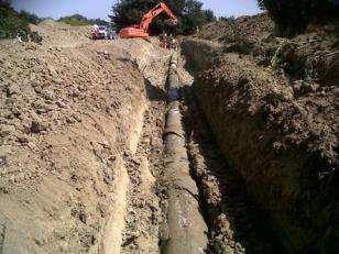
9 4. FIELD TESTS The TRP method has been already tested on site with positive results. The first pipeline cutting and removal field test on a ND 500 (20") pipeline section of about 30 m has been performed in September The second test has been completed in August 2013, on a ND 550 (22") pipeline section of about 50 m, including cutting, removal and filling phases. In the following the main characteristics of the two tests are summarized: Table 1: Field tests summary 1st TEST 2nd TEST Location Cremona (Italy) Minerbio (Italy) Diameter Length 30 m 50 m Pipe material/ Wall thickness Carbon steel, 11.1 mm; polyethylene coating Carbon steel, 10.3 mm; Coal tar coating Soil Silty sand Clay Waterjet cut pressure 6000 bar 4000 bar Helical cut pitch 3 m 3 m Cutting Length - Duration of the cutting phase 32 m - 4 hours 45 m hours Pulling Force - Torque kn - 30 kn m Filling - Expanded clay In the following pages some images of the main phase of the Trenchless Pipeline Removal method (cutting, extraction, filling) are shown: 9
")

10 Figure 9 (a-b) Cutting phase during site tests 10
")


11 Figure 10 (a-b-c-d) Extraction phase during site tests 11

.")
 for the different application, in particular when it is requested soil stability after removal, for")
12 Figure 11 (a-b-c) Filling phase with expanded clay during site tests The expectation from the future field applications is to gather the site data necessary for the assessment of the TPR method. In particular the objectives are: To evaluate the effect of different helical pitch on the same pipe length (about 40/50 m). To investigate the behaviour, applicability and reliability of different filling material (i.e. expanded clay aggregate, eco-compatible bentonite mixtures, dry sand, etc...) for the different application, in particular when it is requested soil stability after removal, for example at road crossings. 12

 for comparison with the site results. 5.")
 - Soil characteristics")
13 To evaluate the effect of the length to be removed and determine the maximum limit of this application, considering that each section can be divided in two, operating from both ends. In addition, a study of the theoretical model of the cut pipe during extraction is being carried out (considering length, helical cut pitch, diameter, soil characteristics, etc..) for comparison with the site results. 5. THEORETICAL MODEL The mathematical simulations of the cut pipe behaviour during the extraction are being carried out. The parameters that affect the model are: - Pipe characteristics (diameter, wall thickness, length, external coating, material) - Soil characteristics - Spiral cut pitch The expected pulling force and rotation necessary for the extraction shall be compared with those recorded during the site tests. This will allow a proper set up of the model. Figure 12 TPR simulation screenshots. 13

 Pipeline external cutting on site")


14 6. OTHER APPLICATION OF WATERJET CUTTING IN THE OIL AND GAS FIELD Other uses of the waterjet cutting in the oil and gas field can be envisaged considering the benefit of this cold cut technology. Possible different uses of the waterjet cutting system are: a) Pipeline external cutting on site for valves installation, tees for branch connection or other special tools (see 13) Figure 13 Pipeline external cutting. b) Bevelling end preparation for steel pipes with very high wall thickness. The waterjet cut technology will be used for the prefabrication of pipes with about 80 mm wall thickness (see Figure 14), with good results in terms of quality of the cut and time compare to other methods. Figure 14 (a-b-c-d) Bevelling end on very high wall thickness steel pipes. 14


15 c) Realization of holes on very high wall thickness steel pipes for weldolet, sweepolet and other special pieces to be welded to the pipes. 7. CONCLUSIONS The positive results of the site tests have demonstrated that the helical cutting of the pipe is the optimal solution for the removal of pipeline sections without trenching. The real potential of this new system, in terms of applicability in different scenarios, is to be verified in the future with the implementation of this method in those areas where the impact of a traditional pipeline removal by trenching is not allowed. With additional site data and further experience the system will be set up and all the operations will be optimized, in order to reduce the time and costs of this application. For the time being, the TPR method can be utilized for pipes with diameters greater than or equal to 10. At present, the TPR system can operate on straight line or elastic bend sections of a pipeline. With regard to the maximum length of the pipeline to be removed, the current goal is to remove up to 200 m that can be obtained by the extraction at both ends. Like all trenchless technologies, TPR is in constant evolution. Hopefully the TPR system, like other trenchless technologies, could evolve over time and could be the solution for the removal of increasing pipeline lengths, thus safeguarding particular environments and making it possible to remove pipelines in certain situations where, to date, abandoning the underground pipe is mandatory. 15
16 8. REFERENCES Chirulli, R. - Manuale di tecnologie No-Dig, Le tecniche e le metodologie di progetto e di calcolo (No-Dig manual: No-Dig Technologies Manual: techniques and methods for design and calculation) Vescovo, C. and Lazzarini, U. - La costruzione di condotte in acciaio nel segno del rispetto ambientale: le Tecnologie Trenchless (Steel pipe construction respecting the environment: Trenchless Technologies) AIW: Associazione Italiana Waterjet (Italian Waterjet Association) 16
CONSTRUCTION SPECIFICATION FOR THE INSTALLATION OF ELECTRICAL CHAMBER
 ONTARIO PROVINCIAL STANDARD SPECIFICATION METRIC OPSS 602 MARCH 1993 CONSTRUCTION SPECIFICATION FOR THE INSTALLATION OF ELECTRICAL CHAMBER 602.01 SCOPE 602.02 REFERENCES 602.05 MATERIALS TABLE OF CONTENTS
PVC Fittings & Laterals for Solid-Wall PVC Sewer Pipe
 Design and Installation Guide PVC Fittings & Laterals for Solid-Wall PVC Sewer Pipe TABLE OF CONTENTS Introduction 2 Products 3 Main-Line Fittings & Service-Line Fittings 3-4 Connections to Dissimilar
7. Allowable Fittings.
 7. Allowable Fittings. a. General Requirements. 1) The fittings listed in this section are generally the allowable fittings for the design of DIP and PVC pipe. For steel pipe and fittings, see Part One,
DUCTILE IRON PIPES AND FITTINGS DETAILED PRODUCTS SPECIFICATIONS
 DUCTILE IRON PIPES AND FITTINGS DETAILED PRODUCTS SPECIFICATIONS General All Materials shall be EN, ISO or equivalent standard and shall be supplied from approved manufacturers. According to the International
Employment Intensive Infrastructure Program (EIIP) in Lebanon ANNEX 2
 in Lebanon ANNEX 2") Employment Intensive Infrastructure Program (EIIP) in Lebanon ANNEX 2 PARTICULAR SPECIFICATIONS FOR THE CONSTRUCITON OF STORM WATER DRAINAGE NETWORK March 2018 BUREAU TECHNIQUE POUR LE DEVELOPPEMENT P.O.B
Employment Intensive Infrastructure Program (EIIP) in Lebanon ANNEX 2 PARTICULAR SPECIFICATIONS FOR THE CONSTRUCITON OF STORM WATER DRAINAGE NETWORK March 2018 BUREAU TECHNIQUE POUR LE DEVELOPPEMENT P.O.B
ORDINANCE ON TECHNICAL REQUIREMENTS FOR CABLE DUCTS
 Pursuant to Article 12, paragraph 1, item 1 and Article 24, paragraph 8 of the Electronic Communications Act (Official Gazette No. 73/08), the Council of the Croatian Post and Electronic Communications
Underground System. Description
 Description Insapipe is a factory fabricated and insulated Underground piping system designed for direct burial into an unlined trench. The product is manufactured generally to British Standard 4508 for
H. Underground Transmission System Design
 H. Underground Transmission System Design In addition to analyzing potential routes, the Company considered several different design technologies for the proposed underground transmission supply lines,
ITEM NO. 824 SERVICE SUPPLY LINES (WATER)
") ITEM NO. 824 SERVICE SUPPLY LINES (WATER) 824.1 DESCRIPTION: This item shall consist of water service supply lines installation and adjustment installed in accordance with these specifications and as directed
ITEM NO. 824 SERVICE SUPPLY LINES (WATER) 824.1 DESCRIPTION: This item shall consist of water service supply lines installation and adjustment installed in accordance with these specifications and as directed
UNIVERSITY OF MISSOURI Hydronic Energy Distribution 2016 Q1
 GENERAL: The scope of this document is to provide instruction for the installation and testing of chilled water piping installed for the University of Missouri. DESIGN GUIDELINES: 1. Materials 1.1. Pipe
San Antonio Water System Standard Specifications for Construction ITEM NO. 824 SERVICE SUPPLY LINES (WATER)
") San Antonio Water System Standard Specifications for Construction ITEM NO. 824 SERVICE SUPPLY LINES (WATER) 824.1 DESCRIPTION: This item shall consist of water service supply lines adjustment and installation
San Antonio Water System Standard Specifications for Construction ITEM NO. 824 SERVICE SUPPLY LINES (WATER) 824.1 DESCRIPTION: This item shall consist of water service supply lines adjustment and installation
SECTION PIPE INSTALLATION
 SECTION 02232 PIPE INSTALLATION A. General The pipe shall be Ductile Iron pipe with Tyton push-on joints and cement lined as described and manufactured in accordance with ANSI/AWWA C151/A21.51. Gaskets
WESTERN UNDERGROUND COMMITTEE GUIDE 3.4 (3.4/00/0565)
") WESTERN UNDERGROUND COMMITTEE GUIDE 3.4 (3.4/00/0565) PLASTIC CONDUIT AND FITTINGS PLACING INSTRUCTION NOTE: This "Guide" summarizes the opinions, recommendations, and practices of the Western Underground
WESTERN UNDERGROUND COMMITTEE GUIDE 3.4 (3.4/00/0565) PLASTIC CONDUIT AND FITTINGS PLACING INSTRUCTION NOTE: This "Guide" summarizes the opinions, recommendations, and practices of the Western Underground
h Installation Manual
 h Installation Manual 1 General Information The installation of HOBAS GRP Pipes is subject to applicable standards and guidelines such as EN 1610 and ISO/ TS 10465-1. Correct installation always requires
San Antonio Water System Standard Specifications for Construction ITEM NO. 812 WATER MAIN INSTALLATION
 ITEM NO. 812 WATER MAIN INSTALLATION 812.1 DESCRIPTION: This item shall consist of water main installation in accordance with these specifications and as directed by the Engineer. 812.2 MATERIALS: The
SECTION DUCTILE IRON FITTINGS. A. This section includes materials, installation, and testing of ductile iron fittings 48 inches and smaller.
 PART 1 - GENERAL 1.1 DESCRIPTION A. This section includes materials, installation, and testing of ductile iron fittings 48 inches and smaller. 1.2 RELATED WORK SPECIFIED ELSEWHERE A. Section 01300 Record
CS-13 TRENCHLESS TECHNOLOGY TABLE OF CONTENTS
 TABLE OF CONTENTS CS-13.0 Trenchless Technology... 1 CS-13.1 Location of Existing Services... 1 CS-13.2 Alignment... 1 CS-13.3 Directional Drilling... 1 CS-13.4 Pipe Thrusting... 2 CS-13.5 Guided Boring/Auger
CONSTRUCTION SPECIFICATION FOR ADJUSTING OR REBUILDING MAINTENANCE HOLES, CATCH BASINS, DITCH INLETS, AND VALVE CHAMBERS
 ONTARIO PROVINCIAL STANDARD SPECIFICATION METRIC OPSS 408 NOVEMBER 2015 CONSTRUCTION SPECIFICATION FOR ADJUSTING OR REBUILDING MAINTENANCE HOLES, CATCH BASINS, DITCH INLETS, AND VALVE CHAMBERS TABLE OF
San Antonio Water System Standard Specifications for Construction ITEM NO. 848 SANITARY SEWERS
 ITEM NO. 848 SANITARY SEWERS 848.1 DESCRIPTION: This item shall govern the furnishing, installation and jointing of sanitary sewer pipe of the size and type specified by the project's plans and specifications.
SANITARY SEWERS. B. Construct or relocate building sanitary sewer services, stubs, and connections.
 SANITARY SEWERS PART 1 - GENERAL 1.01 SECTION INCLUDES A. Sanitary Sewer Gravity Mains B. Sanitary Sewer Force Mains C. Sanitary Sewer Services 1.02 DESCRIPTION OF WORK A. Construct sanitary sewer gravity
Brief Discussion on Application of Guided Boring Non-excavation Technology in Repair of Sewage Pipes Mei-Di SHAN1,a,*, Feng ZHOU2,b
 2nd Annual International Conference on Advanced Material Engineering (AME 2016) Brief Discussion on Application of Guided Boring Non-excavation Technology in Repair of Sewage Pipes Mei-Di SHAN1,a,*, Feng
INSTALLATION. Step 6. Step 7. Step 8
 INTLLTION The following installation instructions and the relative drawings are given only as an example not considering any peculiarities of the installation site or soil characteristics, or morphology
Exhibit A FOX CHAPEL AUTHORITY STANDARD SPECIFICATIONS FOR MATERIALS AND INSTALLATION OF WATER MAINS
 Exhibit A FOX CHAPEL AUTHORITY STANDARD SPECIFICATIONS FOR MATERIALS AND INSTALLATION OF WATER MAINS Requests for extensions to Authority water mains shall be made in writing by the owner or owners of
GeoEng2000 An International Conference on Geotechnical & Geological Engineering
 GeoEng2000 An International Conference on Geotechnical & Geological Engineering 19-24 November 2000 Melbourne Exhibition and Convention Centre Melbourne, Australia Barrettes : A versatile foundation for
AMENDMENTS TO OPSS 408 (OCT 89) CONSTRUCTION SPECIFICATION FOR ADJUSTING OR REBUILDING MANHOLES, CATCH BASINS, DITCH INLETS AND VALVE CHAMBERS
 CONSTRUCTION SPECIFICATION FOR ADJUSTING OR REBUILDING MANHOLES, CATCH BASINS, DITCH INLETS AND VALVE CHAMBERS") Works and Emergency Services CITY OF TORONTO WATER AND WASTEWATER SERVICES STANDARD CONSTRUCTION SPECIFICATIONS TS 408 November 2010 AMENDMENTS TO OPSS 408 (OCT 89) CONSTRUCTION SPECIFICATION FOR ADJUSTING
Works and Emergency Services CITY OF TORONTO WATER AND WASTEWATER SERVICES STANDARD CONSTRUCTION SPECIFICATIONS TS 408 November 2010 AMENDMENTS TO OPSS 408 (OCT 89) CONSTRUCTION SPECIFICATION FOR ADJUSTING
TRENCHLESS CONSTRUCTION (BORING, JACKING, AND TUNNELING)
") PART 1 - GENERAL TRENCHLESS CONSTRUCTION (BORING, JACKING, AND TUNNELING) 1.01 SECTION INCLUDES A. Trenchless Installation of Carrier Pipe with Casing Pipe B. Trenchless Installation of Carrier Pipe without
PART 1 - GENERAL TRENCHLESS CONSTRUCTION (BORING, JACKING, AND TUNNELING) 1.01 SECTION INCLUDES A. Trenchless Installation of Carrier Pipe with Casing Pipe B. Trenchless Installation of Carrier Pipe without
Expert in Tunneling Systems & Trenchless Technology (HDD, Microtunneling, Pipe Jacking, Thrustboring, Sheet Piling)
") INDEX 2 Company Profile 4 Technical Description 13 Organization Chart 6 Quality & HSE 19 Services Offered 8 Certification 22 COMPANY PROFILE Company Profile 4 Thrustboring Technology Contracting Company
INDEX 2 Company Profile 4 Technical Description 13 Organization Chart 6 Quality & HSE 19 Services Offered 8 Certification 22 COMPANY PROFILE Company Profile 4 Thrustboring Technology Contracting Company
TCC/SHORE TRANSIT BUS MAINTENANCE FACILITY - PHASE II
 SECTION 221313 - FACILITY SANITARY SEWERS PART 1 - GENERAL 1.1 RELATED DOCUMENTS A. Drawings and general provisions of the Contract, including General and Supplementary Conditions and Division 01 Specification
Innovation in Joint Restraint Systems for PVC Pressure Pipe and Fittings. Clean & Safe Drinking Water Workshop. Wednesday, March 25, 2015
 Innovation in Joint Restraint Systems for PVC Pressure Pipe and Fittings Clean & Safe Drinking Water Workshop Wednesday, March 25, 2015 Thrust forces Gasketed joints are made to seal and not to restrain,
APPENDIX I. Conceptual Design - Salem Road and McKay Road Trunk Watermain and Sanitary Sewer
 APPENDIX I Conceptual Design - Salem Road and McKay Road Trunk Watermain and Sanitary Sewer THE CITY OF BARRIE PROJECT NO. 15M-00594-01 CONCEPTUAL DESIGN SALEM ROAD AND MCKAY ROAD TRUNK WATERMAIN AND SANITARY
SECTION CS-2. TRENCH EXCAVATION CONSTRUCTION STANDARDS
 SECTION CS-2. TRENCH EXCAVATION CONSTRUCTION STANDARDS CS-2-01. GENERAL: Trench excavation shall conform with the City Standard Specifications. In general a trench is defined as an excavation in which
CONSTRUCTION SPECIFICATION FOR INSTALLATION OF ELECTRICAL CHAMBERS
 ONTARIO PROVINCIAL STANDARD SPECIFICATION OPSS.PROV 602 NOVEMBER 2017 CONSTRUCTION SPECIFICATION FOR INSTALLATION OF ELECTRICAL CHAMBERS TABLE OF CONTENTS 602.01 SCOPE 602.02 REFERENCES 602.03 DEFINITIONS
CONSTRUCTION SPECIFICATION FOR INSTALLATION OF ELECTRICAL CHAMBERS
 ONTARIO PROVINCIAL STANDARD SPECIFICATION METRIC OPSS 602 NOVEMBER 2008 CONSTRUCTION SPECIFICATION FOR INSTALLATION OF ELECTRICAL CHAMBERS TABLE OF CONTENTS 602.01 SCOPE 602.02 REFERENCES 602.03 DEFINITIONS
SEISMIC BEHAVIOR OF CONFINED MASONRY WALLS REINFORCED WITH WELDED STEEL AND DUCTILE STEEL
 15 th International Brick and Block Masonry Conference Florianópolis Brazil 2012 SEISMIC BEHAVIOR OF CONFINED MASONRY WALLS REINFORCED WITH WELDED STEEL AND DUCTILE STEEL San Bartolomé Angel 1 ; Quiun,
STRENGTH CONSEQUENCE MINIMIZATION OF DIGGING OFF BURIED GAS PIPELINE AT ISOLATION COAT RENOVATION REALIZED DURING OPERATION
 STRENGTH CONSEQUENCE MINIMIZATION OF DIGGING OFF BURIED GAS PIPELINE AT ISOLATION COAT RENOVATION REALIZED DURING OPERATION Assoc. Prof. MSc. Roland JANČO, PhD. Institute of Applied Mechanics and Mechatronics,
Imperial s Sarnia Products Pipeline. Waterdown to Finch Project
 Imperial s Sarnia Products Pipeline Waterdown to Finch Project Safety and reliability: pipeline replacement from Waterdown to Finch Imperial s Sarnia Products Pipeline is important infrastructure that
Trenchless Pipeline Crossings
 Trenchless Pipeline Crossings Overview Where we started Horizontal Directional Drilling 1960 s Evolution of the process Where we are today HDD Microtunneling Direct Pipe Crossing Process Where we re going
CONSTRUCTION SPECIFICATION FOR PIPE SUBDRAINS
 ONTARIO PROVINCIAL STANDARD SPECIFICATION OPSS.MUNI 405 NOVEMBER 2017 (Formerly OPSS 405, November 2008) Note: The MUNI implemented in November 2017 replaces OPSS 405 COMMON, November 2008 with no technical
SUPPLEMENTAL SPECIFICATIONS TO STANDARD SPECIFICATIONS FOR WATER MAIN AND SERVICE LINE INSTALLATION NO. 2611
 Revised October 10, 2014 SUPPLEMENTAL SPECIFICATIONS TO STANDARD SPECIFICATIONS FOR WATER MAIN AND SERVICE LINE INSTALLATION NO. 2611 Water Main and Service Line Installation shall be in accordance with
CONSTRUCTION SPECIFICATION FOR FOOTINGS AND PADS FOR ELECTRICAL EQUIPMENT
 ONTARIO PROVINCIAL STANDARD SPECIFICATION OPSS.MUNI 616 APRIL 2018 CONSTRUCTION SPECIFICATION FOR FOOTINGS AND PADS FOR ELECTRICAL EQUIPMENT TABLE OF CONTENTS 616.01 SCOPE 616.02 REFERENCES 616.03 DEFINITIONS
CONSTRUCTION SPECIFICATION FOR PIPELINE AND UTILITY INSTALLATION IN SOIL BY HORIZONTAL DIRECTIONAL DRILLING
 ONTARIO PROVINCIAL STANDARD SPECIFICATION METRIC OPSS 450 NOVEMBER 2O12 CONSTRUCTION SPECIFICATION FOR PIPELINE AND UTILITY INSTALLATION IN SOIL BY HORIZONTAL DIRECTIONAL DRILLING TABLE OF CONTENTS 450.01
CONSTRUCTION SPECIFICATION FOR PIPE SUBDRAINS
 ONTARIO PROVINCIAL STANDARD SPECIFICATION METRIC OPSS 405 NOVEMBER 2008 CONSTRUCTION SPECIFICATION FOR PIPE SUBDRAINS TABLE OF CONTENTS 405.01 SCOPE 405.02 REFERENCES 405.03 DEFINITIONS 405.04 DESIGN AND
Design of pipeline installation D-GEO PIPELINE
 Design of pipeline installation D-GEO PIPELINE Design of pipeline installation D-GEO PIPELINE General Pipelines are an important part of the underground infrastructure. They are the lifelines of our modern
CONSTRUCTION SPECIFICATION FOR TRENCHING, BACKFILLING, AND COMPACTING
 ONTARIO PROVINCIAL STANDARD SPECIFICATION METRIC OPSS.MUNI 401 NOVEMBER 2015 (Formerly OPSS 401, November 2013) CONSTRUCTION SPECIFICATION FOR TRENCHING, BACKFILLING, AND COMPACTING TABLE OF CONTENTS 401.01
Special Provision for LRFD Pipe Culvert Burial Tables
 All Regional Engineers Omer M. Osman, P.E. Special Provision for LRFD Pipe Culvert Burial Tables January 9, 2015 This special provision was developed by the Bureau of Bridges and Structures as a result
BILL OF QUANTITY ENGINEERING & MANAGEMENT CONSULTING CENTRE. "Beit Hanoun Emergency Water Supply Project"
 "Beit Hanoun Emergency Water Supply Project" " Rehabilitation and Construction of Beit Hanoun Water Network " BILL OF QUANTITY ENGINEERING & MANAGEMENT CONSULTING CENTRE Bill of Quantities PREAMBLE TO
Design of pipeline installation. D-Geo Pipeline
 Design of pipeline installation D-Geo Pipeline Design of pipeline installation D-Geo Pipeline General Pipelines are an important part of the underground infrastructure. They are the lifelines of our modern
PVC PRESSURE FITTINGS
 GUIDE FOR PVC PRESSURE FITTINGS TABLE OF CONTENTS Introduction 3 Standards and Specifications 3 Products 4 Manufacturing Methods 8 Fabricated Fittings 8 Injection-Molded Fittings 9 Machined Couplings 9
Task 5. Christopher Mack Zack Kaldy MET 330 Fluid Mechanics November 8, Purpose
 Purpose Task 5 Christopher Mack Zack Kaldy MET 330 Fluid Mechanics November 8, 2015 For the fifth task of this project we are asked to specify the layout of the piping system, the material type and sizes
FLEXWELL FHK. Flexible district heating pipe
 FLEXWELL FHK Flexible district heating pipe The intelligent alternative: safe and economical through simplified planning and minimal civil construction costs Safety furnished by the corrugated steel casing
TRENCHLESS CONSTRUCTION (BORING, JACKING, AND TUNNELING)
") PART 1 - GENERAL TRENCHLESS CONSTRUCTION (BORING, JACKING, AND TUNNELING) 1.01 SECTION INCLUDES A. Trenchless Installation of Carrier Pipe with Casing Pipe B. Trenchless Installation of Carrier Pipe without
PART 1 - GENERAL TRENCHLESS CONSTRUCTION (BORING, JACKING, AND TUNNELING) 1.01 SECTION INCLUDES A. Trenchless Installation of Carrier Pipe with Casing Pipe B. Trenchless Installation of Carrier Pipe without
SECTION UTILITY BACKFILL MATERIALS
 SECTION 31 23 23 UTILITY BACKFILL MATERIALS PART 1: GENERAL 1.01 SECTION INCLUDES A. Material Classifications B. : 1. Concrete sand 2. Gem sand 3. Pea gravel 4. Crushed stone 5. Crushed concrete 6. Bank
is a patented system.
 Funnel The is a "high performance" drainage system where a ductile iron "grating" collects rainwater from the surface and, through a ductile iron "cone", conveys it into the HD-PE "pipe" with calculated
SPECIFICATION : BORING AND JACKING
 SPECIFICATION 330524: BORING AND JACKING PART 1.0 GENERAL 1.1 DESCRIPTION 1.1.1 The work of this specification includes all labor, machinery, construction equipment and appliances required to perform in
Copper-Type K soft Drawn 40, 50 HDPE 100 and larger
 1.0 GENERAL 1.1 Scope 1.1.1 The work covered by this section involves the installation of water and sewer service connections and all other associated work. 1.2 Authorization 1.2.1 Do not install service
CONSTRUCTION SPECIFICATION FOR FOOTINGS AND PADS FOR ELECTRICAL EQUIPMENT
 ONTARIO PROVINCIAL STANDARD SPECIFICATION METRIC OPSS 616 NOVEMBER 2008 CONSTRUCTION SPECIFICATION FOR FOOTINGS AND PADS FOR ELECTRICAL EQUIPMENT TABLE OF CONTENTS 616.01 SCOPE 616.02 REFERENCES 616.03
EI INSTALLATION OF UNDERGROUND CABLES - LV TO 132KV
 Network(s): Summary: ENGINEERING INSTRUCTION EI 02-0019 INSTALLATION OF UNDERGROUND CABLES - LV TO 132KV EPN, LPN, SPN This engineering instruction details the minimum requirements acceptable for the installation
FABRICATED STEEL PIPE AND SPECIALS
 SECTION 02420 - PART 1 -- GENERAL 1.1 WORK OF THIS SECTION A. The WORK of this Section includes providing fabricated steel pipe, specials and connections to new and existing piping. Polyurethane and fusion
TABLE OF CONTENTS
 DIVISION 33: SEWER AND SEPTIC SYSTEMS 33 3633 UTILITY SEPTIC TANK DRAINAGE FIELD TABLE OF CONTENTS 33 0000-1 SECTION 33 3633-- UTILITY SEPTIC TANK DRAINAGE FIELD PART 1 - GENERAL 1.1 SUMMARY A. Includes
SECTION FIRE HYDRANTS
 SECTION 21 11 10 PART 1. GENERAL 1.1 SUMMARY: A. Work consists of furnishing and installing new fire hydrants, (boot with ductile iron retainer gland, standpipe and hydrant complete) plus constructing
All Regional Engineers. Omer M. Osman, P.E. Special Provision for LRFD Pipe Culvert Burial Tables. July 25, 2014
 All Regional Engineers Omer M. Osman, P.E. Special Provision for LRFD Pipe Culvert Burial Tables July 25, 2014 This special provision was developed by the Bureau of Bridges and Structures as a result of
Special Provision No. 421F01 April 2006
 RIGID PIPE CULVERTS Item No. FLEXIBLE PIPE CULVERTS Item No. CSP ARCH CULVERTS Item No. STRUCTURAL PLATE CSP Item No. CORRUGATED STEEL PIPE EXTENSIONS Item No. ROCK EXCAVATION FOR CULVERTS Item No. CLAY
Installation Guidelines
 815 NE 172 nd Avenue Vancouver, WA 98684 877-694-0141 Installation Guidelines Installation steps include job planning, layout, excavating and preparing the soil subgrade, applying geotextiles (optional),
JUST THE FACTS CONCRETE PIPE VS. HDPE
 JUST THE FACTS CONCRETE PIPE VS. HDPE Just the FACTS! DRAINAGE PIPE PERFORMANCE AND DESIGN COMPARISON CONCRETE VS. HDPE Contents Current Standards............................2 Corrugation Growth and its
1 Revised: 2019 Edition
 STORM SEWERS PART 1 - GENERAL 1.01 SECTION INCLUDES A. Storm Sewers B. Abandonment of Storm Sewers 1.02 DESCRIPTION OF WORK A. Construct storm sewers. B. Abandon storm sewers. 1.03 SUBMITTALS Comply with
WM2012 Conference, February 26 March 1, Phoenix, Arizona, USA
 Design, Development, Pre-Testing and Preparation for Full Scale Cold Testing of a System for Field Remediation of Vertical Pipe Units at the Hanford Site 618-10 Burial Grounds -12495 Stephen Halliwell,
Imperial s Sarnia Products Pipeline
 Imperial s Sarnia Products Pipeline Waterdown to Finch Project Community Information Session Imperial s Waterdown to Finch Project Important infrastructure to the Greater Toronto and Hamilton Area (GTHA).
Press Release. Rehabilitation of oil pipelines with flexible high pressure pipes
 Press Release July 31, 2013 Rehabilitation of oil pipelines with flexible high pressure pipes Network operators all over the world are confronted with increasingly aging pipeline infrastructure. Since
HT-406 Specification Guide
 2.101 Part 1 - General Pre-insulated HDPE-Jacketed Steel Piping Systems suitable for Steam, Condensate Return, and High Temperature Heating Water. 1.1 Pre-insulated Piping - Furnish a complete HDPE jacketed
SECTION PUBLIC WATER SERVICE CONNECTIONS
 SECTION 33 14 14 PUBLIC WATER SERVICE CONNECTIONS PART 1 GENERAL 1.1 SUMMARY A. Section Includes: 1. Pipe and fittings for water service connections to small commercial, light industrial, and residential
SECTION HIGH DENSITY POLYETHYLENE PIPE AND FITTINGS (PRESSURE PIPE)
") SECTION 02623 HIGH DENSITY POLYETHYLENE PIPE AND FITTINGS (PRESSURE PIPE) PART 1 - GENERAL 1.1 SCOPE OF WORK A. Furnish all labor, materials, equipment and incidentals required and install high density
SECTION 02623 HIGH DENSITY POLYETHYLENE PIPE AND FITTINGS (PRESSURE PIPE) PART 1 - GENERAL 1.1 SCOPE OF WORK A. Furnish all labor, materials, equipment and incidentals required and install high density
Meyer, Meyer, LaCroix & Hixson
 NORTH BOLTON AVENUE (LA. HIGHWAY 1) NORTH BOUND LANE NOTICE! 1. NEITHER THE ENGINEER NOR THE OWNER WARRANTS OR GUARANTEES THE PLANS TO BE COMPLETE OR ACCURATE WITH RESPECT TO THE LOCATION OR EXISTENCE
UNDERGROUND UTILITY CONTRACTORS GENERAL TRADE KNOWLEDGE EXAMINATION CONTENT INFORMATION
 UNDERGROUND UTILITY CONTRACTORS GENERAL TRADE KNOWLEDGE EXAMINATION CONTENT INFORMATION Effective September 9, 2014 The General Trade Knowledge portion of the examination is administered daily in Computer
North American Society for Trenchless Technology (NASTT) NASTT s 2016 No-Dig Show. Dallas, Texas March 20-24, 2016 WM-T3-01
 NASTT s 2016 No-Dig Show. Dallas, Texas March 20-24, 2016 WM-T3-01") North American Society for Trenchless Technology (NASTT) NASTT s 2016 No-Dig Show Dallas, Texas March 20-24, 2016 WM-T3-01 A Comprehensive Understanding of ASTM F3097-15 Standard Practice for Installation
North American Society for Trenchless Technology (NASTT) NASTT s 2016 No-Dig Show Dallas, Texas March 20-24, 2016 WM-T3-01 A Comprehensive Understanding of ASTM F3097-15 Standard Practice for Installation
TYPICAL INSTALLATION INSTRUCTIONS
 TYPICAL INSTALLATION INSTRUCTIONS Environment One Grinder Pump Feature Identification 1. Grinder Pump Basin High density polyethylene (HDPE) 2. Accessway Cover Painted Steel 3. Electrical Quick Disconnect
No-Dig Technology is the art and science of pipes, ducts and cables using techniques that minimizes / eliminates the need for excavation, i.e.
 No Dig Technology Introduction: No-Dig Technology is the art and science of installing, repairing or renewing underground pipes, ducts and cables using techniques that minimizes / eliminates the need for
SECTION STORM DRAINAGE SYSTEM Excavating, Backfilling, and Compaction for Utilities Cast-in-place Concrete.
 SECTION 02720 STORM DRAINAGE SYSTEM PART 1 GENERAL 1.01 SUMMARY A. Related Sections: 1. 02221 - Excavating, Backfilling, and Compaction for Utilities. 2. 03300 - Cast-in-place Concrete. 1.02 REFERENCES
SCALE BAR 1:2500 RM OF WOODLANDS OVERALL PLAN - LOW PRESSURE SEWER MAIN. Certificate of Authorization JESSICA MANNESS ENGINEERING, INC. No.
 OF SURVEY OVERALL PLAN - LOW PRESSURE SEWER MAIN 0 50 100 SCALE BAR 1:2500 200 500 THIS IS NOT A LEGAL PLAN - CONCEPT ONLY OF SURVEY PLAN - LOW PRESSURE SEWER MAIN 0 50 100 SCALE BAR 1:2500 200 500 THIS
DIVISION II TECHNICAL SPECIFICATIONS SECTION S-003 SANITARY SEWER FORCE MAIN SYSTEM
 DIVISION II TECHNICAL SPECIFICATIONS SECTION S-003 SANITARY SEWER FORCE MAIN SYSTEM TABLE OF CONTENTS: I. DESCRIPTION:... 2 II. COORDINATION:... 2 III. CONSTRUCTION LAYOUT:... 3 IV. MATERIALS:... 3 V.
San Antonio Water System Standard Specifications for Construction ITEM NO. 813 WATER SERVICE FOR FIRELINES
 ITEM NO. 813 WATER SERVICE FOR FIRELINES 813.1 DESCRIPTION: This item shall consist of water service for fire line installations in accordance with these specifications and as directed by the Engineer.
VALLECITOS WATER DISTRICT SECTION PRECAST REINFORCED CONCRETE MANHOLES
 PART 1 GENERAL 1.1 DESCRIPTION A. This section includes materials, testing, and installation of precast concrete manholes, manhole bases, manhole frames, and covers. 1.2 RELATED WORK SPECIFIED ELSEWHERE
made of ductile iron.
 Solutions - made of ductile iron. Ductile Cast Iron Systems trm.at The Company TRM - Tiroler Rohre TRM develops, manufactures and markets highquality systems for the transport of water and for deep foundation
SECTION C1 DUCTILE IRON PIPE AND FITTINGS GENERAL
 SECTION C1 DUCTILE IRON PIPE AND FITTINGS GENERAL This section covers the furnishing and installation of ductile iron water pipe, fittings, thrust restraint and pipe disinfection. Ductile Iron Pipe MATERIALS
A. This Section includes sanitary waste and vent piping inside the building and to locations indicated.
 SECTION 221316 SANITARY WASTE AND VENT PIPING PART 1 - GENERAL 1.1 RELATED DOCUMENTS A. Drawings and general provisions of the Contract, including General and Supplementary Conditions and Division 01 Specification
SPECIAL SPECIFICATION 6664 Level (3) Communications System
 Communications System") 2004 Specifications CSJ 1200-05-014 SPECIAL SPECIFICATION 6664 Level (3) Communications System 1. Description. A. This Item will govern the installation of all facilities belonging to Level (3) Communications,
2004 Specifications CSJ 1200-05-014 SPECIAL SPECIFICATION 6664 Level (3) Communications System 1. Description. A. This Item will govern the installation of all facilities belonging to Level (3) Communications,
SPECIAL SPECIFICATION 6658 Time Warner Communications System
 2004 Specifications CSJ 1200-05-014 1. Description. SPECIAL SPECIFICATION 6658 Time Warner Communications System A. This Item will govern the installation of all facilities belonging to Time Warner Cable
North End and South End Section Hauled Wastewater Receiving Facilities Page 1 Bid Opportunity No
 Hauled Wastewater Receiving Facilities Page 1 Part 1 General 1.1 SECTION INCLUDES.1 Materials and installation for sewage force mains. 1.2 RELATED SECTIONS.1 CW 2110 Watermains and all specifications referenced
For NGTL to file calculation of operating condition on pull back stress analysis.
 NOVA Gas Transmission Ltd. Exhibit No. B85 National Energy Board Hearing Order GH-001-2014 Undertaking U-10 Submitted November 25, 2014 Response to Undertaking given by Mr. Trout to Chairman Vergette at
PETREX -CNT. Pipe systems for petrol stations Technical details
 PETREX - Pipe systems for petrol stations Technical details Contents 1.0 1.0 Contents 1.10 1.100 System description System description PETREX - 1.11 1.11.01 Product overview Piping, connections, fittings
TECHNOLOGY. Hydromill
 TECHNOLOGY Hydromill Everywhere the diaphragm wall market is moving to higher and higher targets in terms of depth and verticality control. Metro stations, new foundations for residential and commercial
How PGW Manages Pipeline Installation in a Congested Underground. Presentation by Mike Parzanese Project Manager Construction Philadelphia Gas Works
 How PGW Manages Pipeline Installation in a Congested Underground Presentation by Mike Parzanese Project Manager Construction Philadelphia Gas Works Summary Philadelphia by the numbers Philadelphia Gas
DESIGN OF SEWER SYSTEMS
 Wastewater Engineering (MSc program) DESIGN OF SEWER SYSTEMS Prepared by Dr.Khaled Zaher Assistant Professor, Public Works Engineering Department, Faculty of Engineering, Cairo University 1. Sewer Materials
No Dig renovation and installation of systems using polyolefin pipes
 No Dig renovation and installation of systems using polyolefin pipes MEMBER OF Why use No Dig technology with polyolefin pipes? In many of the major cities of the world, the underground pipeline systems
***************************************************************************************************************
 02720 STORM DRAINAGE SYSTEM *************************************************************************************************************** SPECIFIER: CSI MasterFormat 2004 number 33 40 00. ***************************************************************************************************************
Horizontal Directional Drilling
 Horizontal Directional Drilling Horizontal Directional Drilling Why HDD Surface is neither broken nor damaged Restoration and repair are not required No public hazard or traffic disturbance Low social
NCCER Progress Blvd, Alachua, Florida Phone: (888)
") NCCER 13614 Progress Blvd, Alachua, Florida 32615 Phone: (888) 622-3720 E-mail: info@nccer.org PIPELAYER Competencies / Objectives MODULE 24101 - JOB SITE SAFETY 1. Identify and properly use the following
NCCER 13614 Progress Blvd, Alachua, Florida 32615 Phone: (888) 622-3720 E-mail: info@nccer.org PIPELAYER Competencies / Objectives MODULE 24101 - JOB SITE SAFETY 1. Identify and properly use the following
SECTION UTILITY POLYETHYLENE CONTAINMENT PIPE SYSTEMS
 SECTION 02670 UTILITY POLYETHYLENE CONTAINMENT PIPE SYSTEMS PART 1 - GENERAL 1.01 WORK INCLUDED A. Trenching and other excavation. B. Ground water control. C. Pipe bedding. D. Installation of containment
C. Foundation stabilization for pipe and utility structures.
 PART 1 - GENERAL 1.1 SECTION INCLUDES A. Excavating, backfilling, and compacting for utilities, including pipe, structures, and appurtenances. B. Control of water in trenches. C. Foundation stabilization
CONSTRUCTION SPECIFICATION FOR NEW MAINTENANCE HOLE, CATCH BASIN, DITCH INLET, AND VALVE CHAMBER INSTALLATION
 ONTARIO PROVINCIAL STANDARD SPECIFICATION METRIC OPSS 407 NOVEMBER 2015 CONSTRUCTION SPECIFICATION FOR NEW MAINTENANCE HOLE, CATCH BASIN, DITCH INLET, AND VALVE CHAMBER INSTALLATION TABLE OF CONTENTS 407.01
freestone eco Prestige & quality DIY vertical wall Large blocks - 10/m 2 Smooth surface finish No concrete footings
 freestone eco Retaining Wall SystemTM The Freestone ECO Retaining Wall System TM is a more sustainable DIY, vertical retaining wall which is manufactured with up to 40% recycled glass aggregate to provide