Wastewater Disinfection Technologies Study. City of Ames Ames, Iowa
|
|
|
- Shannon Hudson
- 6 years ago
- Views:
Transcription
1 Wastewater Disinfection Technologies Study City of Ames Ames, Iowa Final December 2009
2
3 Executive Summary Introduction The objective of the study is to evaluate wastewater disinfection technologies and select the most appropriate technology to disinfect the effluent from the City of Ames (City) Water Pollution Control Plant (Plant). Selection of the disinfection technology is based on the city s non-monetary selection criteria, capital cost, and life-cycle cost analysis. Disinfection of the plant s effluent is not currently a requirement of the plant s discharge permit. However, the receiving stream for the plant effluent, the South Skunk River, was re-classified an A(1) full-body contact recreational river in The A(1) full-body contact recreation designation sets seasonal (March 15-November 15) in-stream water quality standards for E. Coli, a bacteria used as an indicator of human waste contamination. New E. Coli limits are anticipated in the city s next National Pollutant Discharge Elimination System (NPDES) permit to be potentially issued in The study used design flows consisting of an average daily flow of 7.1 million gallons per day (mgd), an average wet-weather flow of 12.1 mgd, and a peak flow of 20.4 mgd. Methodology The study methodology uses non-monetary criteria developed by city staff to initially rank technologies prior to concept development and cost analysis of the top three to four technologies. The technologies evaluated in the study include sodium hypochlorite (liquid chlorine), chlorine gas, chlorine dioxide, peracetic acid, ultraviolet (UV) light, ozone, and wetlands. Liquid and gas chlorine delivery versus on-site chlorine generation was also considered. The technologies were numerically ranked in collaboration with city staff based on weighted non-monetary criteria, such as safety, effectiveness, operation and maintenance requirements, reliability, green design, and public and regulatory acceptance. Other minor criteria were given positive, negative, or neutral ratings. jmb:mjh:fs2:mp3:22243:06:04:final:disinfectionstudy i Stanley Consultants
4 The highest scored alternatives (sodium hypochlorite, UV light, and peracetic acid) were retained for further consideration and development. City staff also requested development and costing of UV combined with peracetic acid. Wetland technology, with input from recognized wetlands expert Scott Wallace, was determined to be unable to consistently meet the 30-day geometric mean E. Coli bacteria standard of 126 colony forming units per 100 ml. However, city staff requested a polishing wetlands alternative be developed. The results of the concept development and cost analysis were presented to city staff in the form of a draft report for consideration. A public meeting was held on November 9, 2009 to present the various technologies, non-monetary criteria evaluation, concepts and costs, and to receive feedback from the public. The study results and recommendations were presented to and accepted by City Council on November 17, Disinfection Study Alternatives Sodium Hypochlorite Sodium hypochlorite is a liquid chlorine solution commonly known as bleach. A basic liquid hypochlorite chlorination system includes solution tank(s), metering pumps, chemical tubing, a diffuser (to inject the solution into the water), and a contact tank to allow the chemical time to inactivate the bacteria. A building for housing the equipment is normally provided. Leftover chlorine remaining in the wastewater effluent is toxic to aquatic life and must be removed. Sodium bisulfate is typically used for removal of residual chlorine. Some key advantages are that it requires minimal operation and maintenance, can reliably meet the bacterial standard, and has low energy consumption. Some disadvantages are that it has higher chemical costs and requires staff to handle two chemicals. Peracetic Acid A system that uses peracetic acid (PAA) is very similar to a sodium hypochlorite system. A building and contact tank is provided just like the sodium hypochlorite system. PAA breaks down into water and carbon dioxide. However, PAA is a biocide prior to breakdown. Currently, there is no receiving stream standard for PAA, but it is anticipated that an additional chemical will need to be fed to inactivate the PAA prior to release to the receiving stream. Peracetic acid is not a common method of disinfection in the United States but is practiced in Europe. Only a couple facilities in the United States produce peracetic acid, and the nearest facility is in Joliet, Illinois. The advantages of this method of disinfection are similar to sodium hypochlorite. The disadvantages are chemical handling, higher chemical costs, and concerns over chemical availability. UV Light An ultraviolet light (UV) disinfection system is a physical process that transfers electromagnetic (light) energy from a mercury arc lamp to a microbe s genetic material inactivating the microbe. The main components of a UV disinfection system are mercury arc lamps, a reactor, and ballasts. The source of UV radiation is either the low-pressure or medium-pressure mercury arc lamp with low or high intensities. A UV system consists of a channel or channels where the banks of UV lamps are immersed in the wastewater effluent jmb:mjh:fs2:mp3:22243:06:04:final:disinfectionstudy ii Stanley Consultants
5 and a building for housing ancillary equipment and the lights during the non-disinfection season. An advantage is that UV is a reliable, proven technology with minimal chemical handling. The main disadvantage is that it has higher energy consumption than the other studied alternatives. UV/Peracetic Acid This alternative combines the UV and PAA processes. UV is used for the base flows up to 12 mgd. PAA is used for flows greater than 12 mgd when the effluent solids slightly rise, decreasing the efficiency of the UV. The combination allows a reduction in UV equipment sizing and the PAA contact tank. The facilities required include the UV system with building and the PAA system with building and contact tank. Advantages include the use of a proven technology for normal operating periods and low consumable costs. Disadvantages are chemical handling and the fact that PAA is not a demonstrated technology in the U.S. Wetlands Wetlands are a solar-powered ecosystem that acts as a significant sponge for carbon, nutrients, metals, and other constituents such as pharmaceuticals. These constituents are in a dynamic equilibrium and cycle through various forms in the wetlands. Wetlands can also be very effective in de-nitrification systems. Wetlands reduce pathogens through various processes, including settling, filtration, predation, and solar disinfection. The combined effect of these processes often results in a two- to three-log removal rate. However, wetlands are also a source of pathogens due to the wildlife and waterfowl that use them, so the removal efficiency varies with wildlife use. As a result, while wetlands can be thought of as a pathogen reduction technology, they cannot be regarded as an appropriate sole disinfection technology for the City of Ames in the sense that wetlands will not be able to consistently meet the required E. Coli bacteria standard. Use of wetlands can reduce pathogens, but a second disinfection process such as UV will be required to meet discharge limits. A polishing wetland concept that utilizes wetlands combined with UV disinfection was conceptualized. WPCF effluent would discharge to a multi-cell polishing wetland system to further reduce pathogens, achieve some nutrient removal, and attenuate flow fluctuations. The polishing wetlands would then discharge through a UV disinfection system to meet discharge standards. The polishing wetland has the ability to handle fluctuating water levels to attenuate high wet weather flows. This alternative would likely require effluent pumping and pipeline to convey effluent to/from the wetland. Implementation of the wetland alternative will require concurrence of the Iowa Department of Natural Resources on a number of issues including; wetland bottom liner requirements, groundwater separation distance, floodplain-related issues, wetland and effluent quality. Advantages include a multipurpose facility, reduction in pathogens and nutrients, and potential reduction of emerging contaminants. Disadvantages are large space requirements, potential loss of high quality farmland and biosolids land application sites, regulatory issues for design and construction, need for two processes to construct, operate, and maintain, and high capital cost. jmb:mjh:fs2:mp3:22243:06:04:final:disinfectionstudy iii Stanley Consultants
6 Cost Analysis Alternative Description Table E-1 Cost Summary Capital Costs Annual O&M Costs Total 20-Year Present Worth 1 UV Disinfection $1,930,000 $26,000 $2,300,000 2 Sodium Hypochlorite Disinfection $1,480,000 $118,000 $3,000,000 3 Peracetic Acid (PAA) Disinfection $1,010,000 $743,000 $10,400,000 4 UV Disinfection Plus PAA Disinfection 5 Polishing Wetland w/ UV Disinfection Source: Stanley Consultants, Inc. $2,160,000 $44,000 $2,800,000 $5,000,000 $168,000 $7,100,000 A sensitivity analysis was conducted on operations and maintenance costs, and the outcome showed UV still remained the most cost-effective means for disinfection of the plant effluent. Public Input Staff from the Water and Pollution Control Department held a public open house on Monday, November 9, The purpose of the open house was to solicit feedback on the evaluation process used to select the final four alternatives that were evaluated in depth and to learn about public perception of those four alternatives. The open house was publicized on the city web site, and a press release was distributed to area media outlets. Staff also mailed invitations to previous open house attendees for related topics and to every person who provided a comment to the Iowa Department of Natural Resources when the South Skunk River was re-designated with the Class A(1) recreation use. A total of nine people attended the open house. Based on responses shared on feedback forms, the majority of attendees indicated support for ultraviolet disinfection as their preferred alternative. Reasons identified on the feedback forms for the choice included the reliability of the system, the safety of ultraviolet both for employees and surrounding neighbors, and the life-cycle costs. In addition, many of the attendees expressed an interest in including wetlands if an appropriate use could be determined. Reasons cited for this preference included the potential for nutrient removal, the potential for removal of compounds that are not currently regulated, and energy efficiency. Following the public open house, staff and their consulting team again discussed the alternative that seemed most practical for incorporating wetlands into a disinfection system. Because it had been determined that wetlands alone could not achieve consistent compliance with the disinfection standard (which is the ultimate purpose of this project), a wetland system would need to be paired with one of the other disinfection systems. After giving wetlands this additional consideration based on the public input, staff again came to the conclusion that wetlands do not make practical sense as a disinfection technology. It should be pointed out that implementation jmb:mjh:fs2:mp3:22243:06:04:final:disinfectionstudy iv Stanley Consultants
7 of any of the other disinfection technologies does not preclude the future use of wetlands as a nutrient removal technology or as a wet-weather flow technology. Recommended Alternative The recommended disinfection alternative is UV disinfection. UV disinfection provides a safe, reliable method of disinfecting wastewater effluent. The technology is well demonstrated in wastewater disinfection applications. Operation and maintenance are fairly simple with costs relatively low. This process does not introduce any additional constituents into the effluent. The capital cost is somewhat higher than some of the technologies that were further developed, but the overall 20-year present-worth value is the lowest of the technologies. jmb:mjh:fs2:mp3:22243:06:04:final:disinfectionstudy v Stanley Consultants
8 Table of Contents Executive Summary... i Introduction... i Methodology... i Disinfection Study Alternatives... ii Sodium Hypochlorite... ii Peracetic Acid... ii UV Light... ii UV/Peracetic Acid... iii Wetlands... iii Cost Analysis... iv Public Input... iv Recommended Alternative... v Section 1 - Introduction Study Scope Acknowledgements Background NPDES Permit Project Financing Treatment Plant Overview Existing Flows Study Disinfection Design Criteria Section 2 - Selection Methodology General Non-Monetary Criteria Development and Ranking Workshop Matrix Development Disinfection Technology Sodium Hypochlorite Chlorine Gas Chlorine Dioxide Peracetic Acid UV Light jmb:mjh:fs2:mp3:22243:06:04:disinfectionstudy vi Stanley Consultants
9 Ozone Wetlands Disinfection Selection Workshop Section 3 - Alternatives Development General Alternatives Alternative One UV Disinfection Design Concept Major Equipment Preliminary Sizing Location Consumable Estimates Alternative Two Sodium Hypochlorite Design Concept Major Equipment Preliminary Sizing Location Consumable Estimates Alternative Three Peracetic Acid Design Concept Major Equipment Preliminary Sizing Location Consumable Estimates Alternative Four UV Disinfection with Peracetic Acid Design Concept Major Equipment Preliminary Sizing UV Disinfection PAA Disinfection Location Consumable Estimates Alternative Five Wet Weather Wetlands General Design Concept Preliminary Sizing Location Anticipated Performance Section 4 - Cost Analysis General Capital Costs Operation and Maintenance Costs Present Worth Costs Sensitivity Section 5 - Technology Selection General Public Input Advantages and Disadvantages Alternative One UV Disinfection jmb:mjh:fs2:mp3:22243:06:04:disinfectionstudy vii Stanley Consultants
10 Alternative Two Sodium Hypochlorite Disinfection Alternative Three Peracetic Acid (PAA) Disinfection Alternative Four UV Disinfection with PAA Alternative Five Polishing Wetlands with UV Disinfection Selected Alternative Schedule References TABLES Table E-1 Cost Summary... iv Table 1-1 Historical WPCF Flow Parameters ( ) Table 1-2 ADW Data Table 1-3 AWW Data Table 1-4 Flow Frequencies Greater Than 12 MGD ( ) Table 1-5 Study Design Flow Criteria Table 2-1 Weighing Factors Table 2-2 Subjective Matrix Table 2-3 Ranking Matrix Table 2-4 Lower Priority Criterion Matrix Table 4-1 Cost Summary Table 4-2 Alternative One UV Disinfection Capital Costs Table 4-3 Alternative Two Sodium Hypochlorite Capital Costs Table 4-4 Alternative Three Peracetic Acid Capital Costs Table 4-5 Alternative Four UV/Peracetic Acid Capital Costs Table 4-6 Alternative Five Polishing Wetlands with UV Disinfection Table 4-7 Alternative One UV Disinfection Operation and Maintenance Costs Table 4-8 Alternative Two Sodium Hypochlorite Operation and Maintenance Costs Table 4-9 Alternative Three Peracetic Acid Operation and Maintenance Costs Table 4-10 Alternative Four UV/Peracetic Acid Operation and Maintenance Costs Table 4-11 Alternative Five Polishing Wetlands with UV Disinfection Table 4-12 Estimated Present Worth Cost Table 4-13 Sensitivity Estimated Present Worth Cost FIGURES Figure WPCF Historical Flows From jmb:mjh:fs2:mp3:22243:06:04:disinfectionstudy viii Stanley Consultants
11 APPENDICES Appendix A - Concept Sketches... A-1 Appendix B - Disinfection Technologies... B-1 jmb:mjh:fs2:mp3:22243:06:04:disinfectionstudy ix Stanley Consultants
12 Section 1 Introduction Study Scope The purpose of this study is to evaluate technologies for disinfection of the effluent from the City of Ames (City) Water Pollution Control Facility (WPCF) and select the disinfection technology that is most appropriate for the City. Selection of the disinfection technology is based on the City s non-monetary selection criteria, capital cost, and life cycle cost analysis. The disinfection study includes an overview of the plant, an explanation of the disinfection selection methodology, a concept design for each alternative, preliminary cost estimates of capital and O&M for each alternative, and a discussion of the final selection. Acknowledgements We would like to acknowledge the following City of Ames personnel who participated and contributed to this study: John Dunn, Christina Murphy, Kris Evans, Lyle Hammes, Jim McElvogue, Joe Krebs, Darrell Hunter, Fred Hagenmaier, and Eric Anderson. Background The City of Ames WPCF receives and treats wastewater from a square mile service area encompassing an estimated 2009 population of 54,745 people. Wastewater is collected by approximately 200 miles of sewer collection pipes and 5 sanitary lift and pump stations. Wastewater treated at the plant is generated by domestic (residential), commercial, and industry. Major contributors include Iowa State University and United States Department of Agriculture research facilities. Disinfection of the plant s effluent is not currently a requirement of the plant s discharge permit. The receiving stream for the plant effluent, the South Skunk River, was not considered a full body contact recreation river until it was re-classified as an A1 full body contact recreational river in The A1 full body contact recreation designation sets seasonal (March 15-November 15) injmb:mjh:fs2:mp3:22243:06:04:final:disinfectionstudy 1-1 Stanley Consultants
13 stream water quality standards for E. Coli, a bacteria used as an indicator of human waste contamination. New E. Coli limits are anticipated in the City s next National Pollutant Discharge Elimination System (NPDES) permit potentially to be issued in The City s NPDES permit has not been revised from its 1986 plant construction due to regulatory agency inaction. The City is currently following the discharge limits from its 1986 plant construction. This is due to a lawsuit over discharge limit changes during construction. A 1994 court judgment ordered the United States Environmental Protection Agency (EPA) to issue a revised permit to the City, but no revised permit has been issued. The City has re-applied for a new permit in 1998 and The City is not required to disinfect until a new NPDES permit is issued. The City is moving forward proactively because it is appropriate for the community and its moral obligation to be protective of public health. The WPCF produces a very high quality effluent. The City is justifiably proud of their treatment facility s performance and long tradition of good environmental stewardship. NPDES Permit A meeting was held with the Iowa Department of Natural Resources (IDNR) on August 19, 2009 to discuss the E. Coli standards that will be in the City s future permit. The IDNR confirmed that the Ch. 62 rules pertaining to E. Coli NPDES permit limits are being changed in the fall of 2009 and should be effective by December The rule revisions will eliminate the use of a maximum day E. Coli limit and instead only use the geometric mean criteria. The IDNR still needs to make changes to Ch. 61 water quality standards but this should not impact the NPDES limits. The 30-day geometric mean criteria anticipated to be in the City s future permit is 126 colony forming units per 100 milliliters (cfus/100 ml). Project Financing City of Ames has applied for I-JOBS funding for the project. The City intends to finance any amounts not funded by I-JOBS through the Clean Water State Revolving Fund program. The SRF loan will be repaid through sewer use fees. Treatment Plant Overview The WPCF is designed for a maximum wet weather (MWW) flow of 20.4 million gallons per day (mgd), a sustained 30-day average wet weather (AWW) flow of 12.1 mgd and an average daily flow (ADF) of 7.1 mgd. The plant is designed for a peak hour wet weather flow of 36 mgd through its influent pumping system, but only 20.4 mgd through the rest of the treatment train. Flow equalization basins are used to attenuate peak hour wet weather flows to match plant capacity. Flows that exceed the plant s hydraulic capacity of 20.4 mgd are diverted to the EQ basins. The EQ basins can either feed the excess flow back to the head of the plant for treatment, or overflow the equalization basins and combine with the effluent from the cascade aerator for blended discharge. The plant normally operates under mode 4 where the wastewater passes through primary clarifiers, followed by first stage trickling filters, solids contact basins, intermediate clarifiers, second stage trickling filters and final clarifiers. Discharge from the final clarifiers fall over a jmb:mjh:fs2:mp3:22243:06:04:final:disinfectionstudy 1-2 Stanley Consultants

14 stepped cascade aeration structure to re-aerate the wastewater prior to discharge via gravity piping conveyance to the river. The WPCP switches to its wet weather operational regime mode 5 operation when flows go above 12 mgd. In mode 5 final clarification is omitted, and the wastewater passes through the primary clarifiers, first stage trickling filters, solids contact basins, four intermediate clarifiers, and second stage trickling filters before falling over the cascade basin. Existing Flows Daily influent flow measurements from 2003 to July 2009 were reviewed. Figure 1-1 illustrates the WPCP historical flows from WPCF Historical Flows From Figure 1-1 The following flow regimes were determined based on IDNR definitions: Average daily flow (ADF) which is the statistical average of both wet and dry periods. Average dry weather (ADW) flow which is defined as the average flow during dry weather when groundwater is at or near normal, and infiltration and inflow are not occurring. Data from January and February of each year of the dataset were used to derive the ADW flow. jmb:mjh:fs2:mp3:22243:06:04:final:disinfectionstudy 1-3 Stanley Consultants
15 Average wet weather (AWW) flow which is defined as average day flow for the wettest 30-day period. Maximum wet weather (MWW) flow which is defined as the total maximum 24-hour flow received when the groundwater is high and runoff is occurring. Table 1-1 summarizes the historical flows derived from the data. Table 1-1 Historical WPCF Flow Parameters ( ) Parameters Flow (mgd) Date Average Daily Flow (ADF) Avg Minimum Flow /25/2004 Average Dry Weather (ADW) 5.4 Average Wet Weather (AWW) /11/ Maximum Wet Weather (MWW) /12/2008 Notes: 1 30 day period ending on 5/11/2007. Source: City of Ames WPCF Flow Data, Stanley Consultants, Inc. jmb:mjh:fs2:mp3:22243:06:04:final:disinfectionstudy 1-4 Stanley Consultants
16 The ADW flow was derived by averaging the January and February flow data with January and February 2007 flows excluded due to slightly higher than normal 30 and 60 day precipitation. Table 1-2 presents the ADW data. Date Table 1-2 ADW Data Precipitation (in) 30-Day Average 60-Day Average Flow (mgd) 1/31/ /28/ /31/ /29/ /31/ /28/ /31/ /28/ /31/ /29/ /31/ /28/ Average 5.4 Source: City of Ames WPCF Flow Data, Stanley Consultants, Inc. jmb:mjh:fs2:mp3:22243:06:04:final:disinfectionstudy 1-5 Stanley Consultants
17 The two largest maximum 30-day average flows during the period were 15.4 mgd on 6/27/2008 and 11.2 mgd on 5/11/2007. The 99 th percentile flow for the same period is 12.5 mgd. The five largest 30-day average flows, 8.4 mgd (6/21/2004), 11.2 mgd (5/11/2007), 9.5 mgd (5/10/2008), 15.4 mgd (6/27/2008), and 9.1 mgd (5/4/2009), produce an average sustained flow of 10.7 mgd. Rainfall data was also analyzed for the same period to determine wet 30-day periods and corresponding flows. An average wet weather flow of 8.4 mgd was computed by averaging flows from seven 30-day wet weather periods determined by 30-day rainfall totals. Table 1-3 presents the data. Date Table 1-3 AWW Data Precipitation (in) 30-Day Total Maximum 30-Day Average Flow (mgd) 6/21/ /20/ /9/ /12/ /27/ /29/ /24/ Average 8.4 Note: Average 30-day rainfall total for the period is 3.49 inches. Source: City of Ames WPCF Flow Data, Stanley Consultants, Inc. The flow selected as the appropriate maximum 30-day average wet weather (AWW) flow is 11.2 mgd. This flow is consistent with the statistical analysis of the data and represents greater than the 98 th percentile of the wettest 30-day average wet weather flows. The June 27, 2008 flow of 15.4 mgd is not considered representative of the system s normal wettest 30-day average wet weather due to unusual rainfall events. The 30-day period ending June 27, 2008 experienced five rainfall events greater than 1.7 inches with two events exceeding 3 inches totaling inches of precipitation. This amount of precipitation is much greater than the dataset s 99 th percentile value of inches. The 2008 year was exceptionally wet with almost 50 inches of rain recorded, 19 inches above average. MWW flow is defined as the maximum 24-hour flow received when the groundwater is high and runoff is occurring. The MWW of mgd occurred on June 12, The MWW flow and several other high wet weather flows are larger than the 20.4 mgd hydraulic capacity of the plant. Flows in excess of 20.4 mgd are diverted to the EQ basins. Table 1-4 presents how frequently jmb:mjh:fs2:mp3:22243:06:04:final:disinfectionstudy 1-6 Stanley Consultants
18 flows exceed 12 mgd, the threshold when the plant operates in its wet weather flow regime mode 5. Year Table 1-4 Flow Frequencies Greater Than 12 MGD ( ) Number of Days Daily Flow is Greater Than 12 MGD 15 MGD 18 MGD 20.4 MGD Source: City of Ames WPCF Flow Data, Stanley Consultants, Inc. As shown in Table 1-4, daily flows have exceeded plant capacity on six occasions. EQ basins are used more frequently than required to equalize daily flows. EQ basins are used any time influent pumping exceeds 20.4 mgd which occurs for short periods on a more frequent basis than the large daily flow events. Study Disinfection Design Criteria Table 1-5 presents the design criteria used for this study. Current ADF is used for estimating power/chemical costs. Sizing is based on matching existing plant design. Design will take into consideration future expansion of the disinfection facilities when the treatment plant is expanded due to increased flows as a result of growth. Table 1-5 Study Design Flow Criteria Study Criteria Plant Design ADF 7.1 mgd 8.4 mgd AWW 12.1 mgd 12.1 mgd Peak Flow 20.4 mgd (through disinfection facilities) 20.4 mgd Source: Stanley Consultants, Inc., City of Ames The 100-year floodplain elevation at the plant site is MSL. jmb:mjh:fs2:mp3:22243:06:04:final:disinfectionstudy 1-7 Stanley Consultants
19 Section 2 Selection Methodology General This section describes the methodology used to evaluate and select the disinfection technology most appropriate for the City of Ames. Technology selection is based on City staff input and criteria, and public input. The general methodology consists of development of non-monetary criteria to perform initial ranking of technologies prior to concept development and cost analysis of the top three to four technologies. Results of the concept development and cost analysis are presented to City staff in the form of a draft report for consideration. A public meeting is held to present the various technologies, non-monetary criteria evaluation, concepts and costs, and to receive feedback from the public. City staff in consultation with the consultant and with consideration of public input will make the final selection for recommendation to Council who has final authority. Non-Monetary Criteria Development and Ranking Workshop The design team met with the City staff for a kick-off meeting on August 4, 2009 where a list of various non-monetary selection criteria were created and evaluated based on their relative importance. The City s priorities were ranked in four tiers with tier one listing the most important criteria and tier four listing the least important criteria. The preferred disinfection alternatives to be further developed and analyzed for cost are selected based on the following criteria: Tier One Safety Effectiveness - meets flow demands jmb:mjh:fs2:mp3:22243:06:04:final:disinfectionstudy 2-1 Stanley Consultants
20 - achieves regulatory compliance Tier Two Minimal Operator Involvement and Staffing Needs Low Maintenance Requirements Reliability - meets disinfection requirements consistently - has a long life cycle - can work in combination with other disinfection systems Green Design - low energy consumption - small carbon footprint - ancillary benefits Tier Three Positive Public Opinion Regulatory Acceptance Tier Four Electrical Demands Space Requirements Availability Demonstrated/Proven Technology Constructability Nutrient Removal Implications Security Impact of Road Outages Wet Weather Disinfection Flood Plain Impact jmb:mjh:fs2:mp3:22243:06:04:final:disinfectionstudy 2-2 Stanley Consultants
21 Matrix Development The non-monetary selection matrix was developed based on the first three tiers of criteria identified by the City. A subjective matrix was developed for ranking each criteria 1 through 5 for each disinfection technology, with 5 meaning the system meets the criteria and 1 meaning the system does not meet the criteria. A ranking matrix based on point totals was developed by assigning weighing factors for each of the elements of the subjective matrix based on how the City prioritized each criterion. Table 2-1 presents the weighing factors used: Criteria Table 2-1 Weighing Factors Weighing Factor Safety 10 Effectiveness 10 Low Operation Requirements 7 Low Maintenance Requirements 7 Reliable 7 Green Design 7 Positive Public Opinion 5 Regulatory Acceptance 5 Source: Stanley Consultants, Inc. The technology with the most points would be considered most preferred based on technical criteria. In addition, each technology was evaluated for the lower tier criterion based on positive (+), negative (-), or neutral (o) attributes. Disinfection Technology Specific disinfection technologies were selected for the matrix to allow consideration of a broad array of disinfection methods that range from simple and widely-used to complex and innovative. By doing so the City staff had the ability to examine all the characteristics of a variety of disinfection technologies. The disinfection technologies used in the matrix includes: Sodium Hypochlorite Chlorine Gas Chlorine Dioxide Peracetic Acid jmb:mjh:fs2:mp3:22243:06:04:final:disinfectionstudy 2-3 Stanley Consultants
22 UV Light Ozone Wetlands A brief summary of each disinfection technology is listed below. See Appendix B for additional technology information including installation photos, process diagrams and textbook references. Sodium Hypochlorite Sodium hypochlorite is a liquid chlorine solution commonly known as bleach. A basic liquid hypochlorite chlorination system includes solution tank(s), metering pumps, chemical tubing, a diffuser (to inject the solution into the water), and a contact tank to allow the chemical time to inactivate the bacteria. A building for housing the equipment is normally provided. Sodium hypochlorite solution is metered into the wastewater effluent and the chemical is allowed to work in the contact tank for from 30 minutes during average flows to 15 minutes at peak flows. Leftover chlorine remaining in the wastewater effluent is toxic to aquatic life and must be removed to prevent impact on aquatic life in the river. Sodium bisulfate is typically used for removal (dechlorination) of residual chorine. Sodium hypochlorite may be delivered in liquid form or it may be generated on-site. On-site generation requires salt delivery. Chlorine Gas A conventional gas chlorination system usually consists of a supply system, a dosage metering system, a solution discharge system, and control equipment. The supply system includes weighing scales to monitor chlorine usage and a gas withdrawal system of valves and gages for compressed liquid-chlorine containers. The chlorinator features a pressurevacuum regulating valve to reduce the supply pressure of the chlorine gas to a negative (vacuum) level. The gas flow through the chlorinator can be fine-tuned by adjustment of a metering orifice, which is in-line with a vacuum differential regulating valve. Gas flow from the chlorinator passes into an injector, where it is mixed with an outside supply of water or treated wastewater. The chlorine mixture is then pumped through a diffuser mechanism into the influent to the chlorine contact chamber. The chlorine mixture dissolves into hydrochlorous (HOCl) and hydrochloric acid (HCl). The injected wastewater travels through the contact basin for from 30 minutes during average flows to 15 minutes at peak flows to allow the chemicals time to disinfect the wastewater. Leftover chlorine remaining in the wastewater effluent is toxic to aquatic life and must be removed to prevent impact on aquatic life in the river. Dechlorination with sulfur dioxide or sodium bisulfate is required to meet residual chlorine limits. Chlorine gas can either be delivered or be generated on-site. Chlorine Dioxide Chlorine dioxide must be generated on-site due to its explosive nature, instability and short shelf-life. Chlorine dioxide can be generated by combining hydrochloric acid (HCl) or chlorine with sodium chlorite (NaClO2). It can also be produced by the reaction of sodium jmb:mjh:fs2:mp3:22243:06:04:final:disinfectionstudy 2-4 Stanley Consultants
23 hypochlorite (NaOCl) with hydrochloric acid. Equipment typically consists of a chlorine dioxide generator with PLC control, flow sensor, chemical pumping system, and chlorine dioxide and oxidation-reduction potential electrodes. Since chlorine dioxide has such a high oxidation capacity, only a low dose is required to disinfect the treated wastewater. The required concentration dose as well as contact time required for adequate disinfection is less than the requirements for sodium hypochlorite. Chloride dioxide is unstable when in contact with sunlight, but its disinfection capacity is not compromised by the water s ph, temperature and alkalinity. In water, chlorine dioxide is active as a biocide for at least 48 hours; its activity probably outranges that of chlorine. Training, sampling and laboratory testing of chlorite and chlorate byproducts can be costly. Dechlorination of chlorite and chlorate byproducts will likely be required. Further analysis would be necessary to verify chlorine dioxide doses and effluent byproduct concentrations. Peracetic Acid A system that uses peracetic acid (PAA) is very similar to a sodium hypochlorite system. A building and contact tank is provided just like the sodium hypochlorite system. PAA is normally fed at a dose of about half that of sodium hypochlorite for wastewater effluent and requires contact time of approximately 5 minutes. PAA breaks down into water and carbon dioxide. However, PAA is a biocide prior to breakdown. There is no receiving stream criterion for protecting aquatic life, but it is anticipated that sodium bisulfate will need to be fed to inactivate the PAA prior to release to the receiving stream. However, the low initial doses and relatively high probable stream limits, reduces the amount of sodium bisulfate required compared to sodium hypochlorite. Peracetic acid is not a common method of disinfection in the United States, but is practiced in Europe. Only a couple facilities in the United States produce peracetic acid and the nearest facility is in Joliet, IL. Bulk delivery of the chemical is currently not available. The only method of delivery is by 500-lb totes. UV Light An ultraviolet light (UV) disinfection system is a physical process that transfers electromagnetic energy from a mercury arc lamp to an organism s genetic material. The main components of a UV disinfection system are mercury arc lamps, a reactor, and ballasts. The source of UV radiation is either the low-pressure or medium-pressure mercury arc lamp with low or high intensities. Submerged quartz tubes must be routinely removed and cleaned of surface deposits of metal salts and absorbed organics that block UV transmission. Cleaning consists of dipping the quartz tubes in a low strength acid and wiping them down. Most UV systems have the option of installing an automatic wiper that will mechanically clean the quartz tubes on regular intervals. This does not eliminate the need to clean them by hand but it significantly reduces the frequency. jmb:mjh:fs2:mp3:22243:06:04:final:disinfectionstudy 2-5 Stanley Consultants
24 Manufacturers recommend that the lamps be removed from the channels during the disinfection off season to prevent moisture and ice buildup around the equipment. Lamp and ballast replacement is necessary every year to maintain adequate UV intensity. Ozone The components of an ozone system include feed-gas preparation, ozone generation, ozone contacting, and ozone destruction. Air or pure oxygen is used as the feed-gas source and is passed to the ozone generator at a set flow rate. The energy source for production is generated by electrical discharge in a gas that contains oxygen. Ozone generators are typically classified by: The control mechanism (either a voltage or frequency unit). The cooling mechanism (either water, air, or water plus oil). The physical arrangement of the dielectrics (either vertical or horizontal). The name of the inventor. The electrical discharge method is the most common energy source used to produce ozone. Extremely dry air or pure oxygen is exposed to a controlled, uniform high-voltage discharge at a high or low frequency. The dew point of the feed gas must be -76 degrees Fahrenheit or lower. After generation, ozone is fed into a down-flow contact chamber containing the wastewater to be disinfected. The main purpose of the contactor is to transfer ozone from the gas bubble into the bulk liquid while providing sufficient contact time for disinfection. The commonly used contactor types diffused bubble are positive pressure injection, negative pressure, mechanically agitated, and packed tower. Because ozone is quickly consumed, it must be contacted uniformly in a near plug flow contactor. The off-gases from the contact chamber must be treated to destroy any remaining ozone before release into the atmosphere. Wetlands Wetlands will reduce pathogens but cannot be solely depended upon to consistently achieve the targeted permit limits. Wetlands are a solar powered ecosystem that acts as significant sponges (sinks) for carbon, nutrients, metals, and other constituents such as pharmaceuticals. These constituents are in a dynamic equilibrium and cycle through various forms in the wetlands. Wetland sediments are an important part of the storage system for these constituents. Wetlands are essentially an attached growth biological system with a long sludge age ( days). This biological system has a very diverse microbial community with a number of microbial types and forms that are never observed in traditional treatment systems due to their relatively short sludge age. Wetlands can be very effective denitrification systems. jmb:mjh:fs2:mp3:22243:06:04:final:disinfectionstudy 2-6 Stanley Consultants
25 Item Wetlands are designed to be a low energy environment using laminar flow, diffusion, and dispersion to make effective use of wetland volume and minimize release of captured contaminants. Wetlands remove bigger biological particles such as bacteria more efficiently than smaller particles such as viruses that are not easily removed. A 2-3 log removal of fecal coliform to a non-zero background level can be achieved using wetlands. The non-zero background level may be non-detectable up to 1,000 cfu/100 ml concentration. Spikes can be expected and wetland animals such as waterfowl can contribute to the pathogen levels leaving the wetlands. Disinfection Selection Workshop The design team met with the City staff again on September 1, 2009 to present the preliminary technology selection and lower priority (tier 4) criterion matrices for discussion and populating. The following tables present the populated matrices. Sodium Hypochlorite Table 2-2 Subjective Matrix Chlorine Gas Chlorine Dioxide Peracetic Acid UV Light Ozone Wetlands Safety Effectiveness Minimal Operator Involvement/ Staffing Needs Low Maintenance Requirements Reliable Green Design Positive Public Opinion Regulatory Acceptance Total Source: Stanley Consultants, Inc. The subjective matrix results presented in Table 2-2 are then multiplied by the weighing factors presented in Table 2-1 to develop the ranking matrix presented in Table 2-3. jmb:mjh:fs2:mp3:22243:06:04:final:disinfectionstudy 2-7 Stanley Consultants
26 Item Sodium Hypochlorite Table 2-3 Ranking Matrix Chlorine Gas Chlorine Dioxide Peracetic Acid UV Light Ozone Wetlands Safety Effectiveness Minimal Operator Involvement/ Staffing Needs Low Maintenance Requirements Reliable Green Design Positive Public Opinion Regulatory Acceptance Total Source: Stanley Consultants, Inc. The highest ranked alternatives - sodium hypochlorite, peracetic acid, and UV light were retained for populating the lower priority criterion matrix and for further development and cost analysis. The other three alternatives were dropped from further consideration. City staff also requested development and costing of UV combined with peracetic acid to determine if the combined technologies would offer potential efficiency and/or cost advantages. Wetland technology, with input from recognized wetlands expert, Scott Wallace, was determined to not be able to consistently meet the 30-day geometric E. Coli standard of 126 colony forming units per 100 ml. However, City staff requested wetlands alternatives be developed for both a base flow polishing system and as a wet weather flow mitigation alternative. jmb:mjh:fs2:mp3:22243:06:04:final:disinfectionstudy 2-8 Stanley Consultants
27 Item Electrical Demands Space Requirements Table 2-4 Lower Priority Criterion Matrix Sodium Hypochlorite Peracetic Acid UV Light o o - o + + Availability o - o Number of Installations/ Demonstrations Constructability o o o Integration with Nutrient Removal o o o Security o o + Impact of Road Outages Wetlands for EQ Flow Source: Stanley Consultants, Inc o The lower priority criterion matrix provides perspective on how the technologies retained for further development and evaluation compare for each of the lower priority criteria. This perspective is considered during final selection of the preferred technology. jmb:mjh:fs2:mp3:22243:06:04:final:disinfectionstudy 2-9 Stanley Consultants
28 Section 3 Alternatives Development General This section presents the concept designs for the disinfection technologies selected and retained for further development at the September 1st workshop. The concept designs also include preliminary sizing, major equipment, site location, and estimates on consumables such as chemicals and parts. Alternatives The highest ranked alternatives - sodium hypochlorite, peracetic acid, and UV light were retained for further development and cost analysis. The other three alternatives were dropped from further consideration. City staff also requested development and costing of UV combined with peracetic acid to determine if the combined technologies would offer potential efficiency and/or cost advantages. Wetland technology, with input from recognized wetlands expert, Scott Wallace, was determined to not be able to consistently meet the 30-day geometric E. Coli standard of 126 colony forming units per 100 ml. However, City staff requested a wetlands based disinfection alternative be developed using a base flow wetland polishing system with a disinfection technology such as UV. The alternatives being further developed and evaluated are: 1. Ultraviolet (UV) Disinfection 2. Sodium Hypochlorite Disinfection 3. Peracetic Acid Disinfection 4. UV Disinfection with Peracetic Acid jmb:mjh:fs2:mp3:22243:06:04:final:disinfectionstudy 3-1 Stanley Consultants
29 5. Polishing Wetlands with UV Alternative One UV Disinfection Design Concept One horizontal or vertical open channel UV disinfection system will be constructed. The entire system will have the capability of disinfecting a maximum flow of 20.4 mgd. An automatic chemical/mechanical cleaning system will be used along with a flow pacing technology for optimization of power usage. As UV demand decreases, the power level of the lamps decrease accordingly. The system will also have the capability to measure UV transmittance and automatically adjust UV light intensity when wet weather flows occur. Automatic level control will be accomplished by the use of a gate. The disinfected effluent piping will discharge to the head of the effluent structure (cascade aerator). Major Equipment Equipment required for the UV disinfection system will comprise of the UV modules and the electrical enclosures. The system configuration is based on the modules holding the lamps in a horizontal position in the channel. The overall system consists of two banks of lamps installed in a concrete channel. The number of required UV lamps is based on a UV transmittance (UVT) of 65 percent. Past measurements of UVT under mode 4 and mode 5 operations demonstrate values greater than 65 percent. The 2 collimated beam tests recently performed confirms that 65 percent UVT is a representative value to use for UV design. Each bank has 14 modules and each module has 8 lamps for a system total of 224 low-pressure, high-intensity Amalgam lamps. A small davit crane will be installed next to the banks of lamps to lift each module out of the channel for maintenance or storage. An automatic cleaning system will be provided to clean the quartz sleeves using both mechanical and chemical methods. Wiping sequence will be automatically initiated with the capability for manual override. The modules will be connected to the power distribution center and system control center through watertight cables. Each bank will contain a PLCbased controller which continuously monitors and controls the system s following functions: UV monitoring system, bank status, elapsed running time meter, electronic ballasts and other electrical controls. Preliminary Sizing The footprint for the UV disinfection system is relatively small in comparison to most disinfection methods. The minimum channel length required to install the 2 modules and the water elevation control gate will be 34 feet. The channel width will be 4-8. UV lamps should be removed from the channel during the months that disinfection is not required. The lamps should be stored in a dry area that is away from the weather elements. jmb:mjh:fs2:mp3:22243:06:04:final:disinfectionstudy 3-2 Stanley Consultants
30 A building will be constructed over the UV system large enough to allow for lamp storage and the electrical equipment. The lamps will be stored on wall mounted storage racks. A bypass channel will be constructed to divert the flow from the UV system if required for maintenance or when the UV equipment is not installed in the channel. The building will not enclose the bypass channel. The outside dimensions of the UV building will be approximately 20 feet wide and 46 feet long. The total spatial footprint required for the UV disinfection system, with the bypass channel, will be approximately 26 feet wide and 46 feet long. See Appendix A for a concept sketch of the UV disinfection system and the site layout. Location Three site locations were discussed for the proposed disinfection system: south of effluent structure (cascade aerator), south of final clarifiers, east of equalization (EQ) basins. Since the footprint of the UV disinfection system is not very large, it may be constructed in any of the three locations. The site south of the final clarifiers contains a small pond so fill would be required to allow any construction in that location. The site east of the EQ basins is further away from the clarifier control boxes and the cascade aerator so additional piping would be necessary. Additional piping also results in a larger amount of headloss. During maximum flow conditions, the amount of headloss available from the clarifier control boxes to the cascade aerator is approximately 1.13 feet. If the UV disinfection system is constructed east of the EQ basins, the effluent must be pumped to the head of the cascade aerator. Hydraulically, constructing the UV disinfection system south of the cascade aerator is the best option. The length of conduit connecting the UV disinfection system to the clarifier control boxes and the cascade aerator would be minimized. The amount of headloss through the disinfection system would be minimized and a pumping system would not be necessary. Consumable Estimates The only items that must be delivered on a regular basis for a UV disinfection system are lamps. UV lamps are warranted for 12,000 hours of operation. After 12,000 hours of use they must be replaced to maintain adequate UV intensity. Approximately 30 lamps will need replacement each year. Power is the primary consumable with UV disinfection. Based on slightly higher than average flow conditions of 8.1 mgd the average power draw from the UV disinfection system is 17.5 kw. The maximum power draw is 44 kw when the system is disinfecting maximum flow conditions of 20.4 mgd. City staff has reviewed the power requirements of the UV disinfection system with the electric power consultant and reports that the plant switchgear is adequate to add the UV disinfection system power demand. The on-site electric generation system also is reported to jmb:mjh:fs2:mp3:22243:06:04:final:disinfectionstudy 3-3 Stanley Consultants
31 have adequate capacity for the UV disinfection system power demand in the event of a mainline power outage. Alternative Two Sodium Hypochlorite Design Concept A sodium hypochlorite/bisulfate pumping and metering system will be constructed to disinfect a maximum flow of 20.4 mgd. Three 5,000 gallon bulk tanks will be provided for sodium hypochlorite. A 3-tank storage capacity of 15,000 gallons will provide flexibility when sodium hypochlorite doses fluctuate and continuous wet weather events occur. Normally, only two tanks will be necessary. However, the third tank allows additional chemical to be procured when wet weather periods increase chemical demands and the plant access road conditions deteriorate. Two tanks will provide approximately 22 days of storage during slightly higher than average flow conditions of 8.1 mgd at a chemical dosage of 8 parts per million (ppm). Two tanks will also provide two full weeks of storage under a continuous design AWW flow of 12.1 mgd. The chemical dose of 8 ppm is a commonly used dose for activated sludge plant effluent. If the chemical dosage fluctuates +/- 2 ppm, 2 tanks will provide between days of storage when considering the 8.1 and 12.1 mgd flow conditions. During heavy wet weather events, the third 5,000 gallon tank may be used for extra storage. Three tanks will provide approximately 30 days of storage capacity during continuous 8.1 mgd flows and 22 days of storage capacity for continuous design AWW flows of 12.1 mgd at a chemical dosage of 8 ppm. The highest flows recorded in the last seven years occurred in June The 7 day average flow for this time period is 19.8 mgd. The three 5,000 gallon tanks provide approximately 10 days of chemical storage when flows are at 19.8 mgd and about 9.5 days when flows are at 20.4 mgd. Two 550 gallon tanks will be provided for sodium bisulfate storage. Typically 1 tank will provide 30 days of storage at continuous 8.1 mgd flow conditions using a chemical dosage of 1 ppm. Both tanks will provide approximately 45 days of storage when flows are maintained at the design AWW flow of 12.1 mgd. If chemical dosage increases to 2 ppm, 2 tanks will provide approximately 34 days of storage at 8.1 mgd flow and 22 days of storage at a 12.1 mgd flow. The contact basins are sized to allow a minimum retention time of 30 minutes for a flow of 12.1 mgd and a 15 minute retention time during MWW flows of 20.4 mgd. Two tanks will be constructed, each tank half of the required volume. The sodium hypochlorite will be injected into the upstream portion of the contact basin and the sodium bisulfate will be injected into the downstream portion of the contact basin. The disinfected effluent will discharge to the head of the cascade aerator. jmb:mjh:fs2:mp3:22243:06:04:final:disinfectionstudy 3-4 Stanley Consultants
32 Major Equipment The sodium hypochlorite metering pump system will include three 50 percent duty metering pumps and a chlorine analyzer with controls. The 5,000 gallon sodium hypochlorite tanks are estimated to have a diameter of 102 inches and a height of 152 inches. The sodium bisulfate metering pump system will also have three 50 percent duty metering pumps. The 550 gallon sodium bisulfate tanks are estimated to have a diameter of 48 inches and a height of 75 inches. Additional pump and metering accessories will include back pressure valves, pressure relief valves, injection check valves and containment areas for both sodium hypochlorite and sodium bisulfate systems. An eye wash shower will be located inside the chemical storage building. Preliminary Sizing Each contact basin has four channel passes. The channel is six feet wide and eight feet deep. Each channel pass is 88 feet long. The estimated footprint for the contact basins is 64 feet wide and 90 feet long. The chemical storage and metering equipment will be stored in an enclosed building near or on top of the contact basins. The building will also include an electrical room. The estimated footprint for the chemical storage building is 34 feet wide and 36 feet long. Assuming that the chemical storage building is constructed next to the contact basins, the estimated spatial footprint of the sodium hypochlorite disinfection system is approximately 65 feet wide and 124 feet long. See Appendix A for a concept sketch of the sodium hypochlorite system and the site layout. Location The three site locations proposed for the disinfection system are south of the cascade aerator, south of the final clarifiers and east of the EQ basins. The site east of the EQ basins is the furthest away from the final clarifiers and the cascade aerator so piping cost would be significant. Additional piping also results in a larger amount of headloss. Only 1.13 feet of head is available between the clarifier control box and the cascade aerator, so the effluent will most likely be pumped to the head of the cascade aerator. The location on the south side of the final clarifiers does not require as much piping but a portion of the existing pond must be filled in. The cost of site development in this location is economically unfavorable. Hydraulically, constructing the chlorination system south of the cascade aerator is the best option. The length of conduit connecting the contact basin to the clarifier control boxes and the cascade aerator would be minimized. The amount of headloss through the chlorination system would be minimized and a pumping system would not be necessary. jmb:mjh:fs2:mp3:22243:06:04:final:disinfectionstudy 3-5 Stanley Consultants
33 A small parking lot configured for spill containment will extend from the access road alongside the chemical building to allow the chemical delivery trucks easy access to the chemical bulk tanks. Consumable Estimates Sodium hypochlorite and sodium bisulfate are the two items that need to be supplied on a regular basis. The sodium hypochlorite will be delivered approximately every two to three weeks. The estimated volume is based on slightly higher than average flow conditions of 8.1 mgd and a dosage of 8 ppm. Approximately 450 gallons of sodium hypochlorite will be consumed each day. Two 5,000 gallon tanker trucks will come on site every 2 to 3 weeks to refill the bulk tanks. The sodium bisulfate will be delivered every 45 days. The estimated volume is based on 8.1 mgd flow and a dosage of 1 ppm. Approximately 16 gallons of sodium hypochlorite will be consumed each day. Alternative Three Peracetic Acid Design Concept A peracetic acid (PAA) pumping and metering system will be constructed to disinfect a maximum flow of 20.4 mgd. At this time PAA is only delivered in 300 gallon totes. The totes cannot be stacked so chemical storage utilizes a large amount of space. Twenty-one days of storage, at consistent flows of 8.1 mgd, will be provided within the chemical building allowing enough space for 17 PAA totes. Seventeen totes will provide approximately 14 days of chemical storage if flows are maintained at a AWW flow of 12.1 mgd. The contact basins are sized to allow a minimum retention time of 10 minutes during AWW flows of 12.1 mgd and a 5 minute retention time during MWW flows. Two tanks will be constructed, each tank half of the required volume. The PAA will be injected into the upstream portion of the contact basin. The disinfected effluent will discharge to the head of the cascade aerator. Major Equipment The PAA metering pump system will include three 50 percent duty metering pumps. Additional accessories for pumping and metering will include back pressure valves, pressure relief valves, injection check valves and containment areas. The 300 gallon totes cannot be stacked and space must be allowed in between each tote. Each tote is 4 feet wide, 4 feet high, and 4 feet long. A small, electric pallet truck will be required to move the totes. An eye wash shower will be located inside the chemical storage building. jmb:mjh:fs2:mp3:22243:06:04:final:disinfectionstudy 3-6 Stanley Consultants
34 Preliminary Sizing Each PAA contact basin has four channel passes. The channel is four feet wide and eight feet deep. Each channel pass is 44 feet long. The estimated footprint for the contact basins is 46 feet wide and 46 feet long. The chemical storage and metering equipment will be stored in an enclosed building near or on top of the PAA contact basins. The building will include an electrical room. The estimated footprint for the chemical storage building is 28 feet wide and 51 feet long. The ceiling will be high enough to install bulk storage tanks if PAA distributors incorporate liquid tank distribution in the future. Assuming that the chemical storage building is constructed next to the PAA contact basins, the total footprint of the PAA disinfection system is approximately 55 feet wide and 110 feet long. See Appendix A for a concept sketch of the PAA disinfection system and the site layout. Location The three site locations proposed for the disinfection system are south of the cascade aerator, south of the final clarifiers and east of the EQ basins. The site east of the EQ basins is the furthest away from the final clarifiers and the cascade aerator so piping cost would be significant. Additional piping also results in a larger amount of headloss. Only 1.13 feet of head is available between the clarifier control box and the cascade aerator, so the effluent will most likely be pumped to the head of the cascade aerator. The location on the south side of the final clarifiers does not require as much piping but a portion of the existing pond must be filled in. The cost of site development in this location is economically unfavorable. Hydraulically, constructing the PAA system south of the cascade aerator is the best option. The length of conduit connecting the PAA contact basin to the clarifier control boxes and the cascade aerator would be minimized. The amount of headloss through the PAA system would be minimized and a pumping system would not be necessary. A small parking lot will extend from the access road alongside the chemical building to allow the chemical delivery trucks easy access inside the building. Consumable Estimates Peracetic acid is the only item that needs to be supplied on a regular basis. The estimated PAA delivery requirements are a semi-trailer load every two weeks. PAA has a shelf life of approximately one year. Therefore, more PAA can be delivered for wet weather periods when plant access roads deteriorate. The estimated volume is based on a flow of 8.1 mgd and a dosage of 5 ppm. Approximately 237 gallons of PAA will be consumed each day. If flows are maintained at 12.1 mgd, the chemicals will last for approximately 14 days. One flat bed truck will typically arrive on site every 10 days to replace the empty totes during frequent AWW events. jmb:mjh:fs2:mp3:22243:06:04:final:disinfectionstudy 3-7 Stanley Consultants
35 Chemical quenching of PAA may be necessary to reduce its oxidation potential before being emitted into the South Skunk River. Sodium bisulfate will most likely be used. The quantity of sodium bisulfate cannot be determined until the IDNR establishes the effluent limits for PAA. The dosage of PAA used for disinfection is less than sodium hypochlorite and the PAA effluent limits will most likely be higher than the chlorine limits. Based on this understanding the amount of sodium bisulfate used to quench the PAA will be less than the volume used to quench the sodium hypochlorite. Alternative Four UV Disinfection with Peracetic Acid Design Concept One horizontal or vertical open channel UV disinfection system will be constructed as well as a peracetic acid (PAA) pumping and metering system. The entire system will have the capability of disinfecting a maximum flow of 20.4 mgd. The PAA disinfection system will be a branch off of the effluent line between the clarifier control boxes and the UV disinfection system. The branch to the PAA system will be isolated with a solenoid valve controlled by a flow meter. The UV disinfection system will disinfect flows up to 12 mgd. When plant flows exceed 12 mgd, the plant will switch their operations to mode 5. The valve isolating the PAA disinfection system will open and flow will pass through both UV and PAA disinfection. The PAA disinfection system will have a maximum capacity of 8.4 mgd. An automatic chemical/mechanical cleaning system will be used for the UV disinfection system along with a flow pacing technology for optimization of power usage. As UV demand decreases, the power level of the lamps decreases accordingly. The system will also have the capability to measure UV transmittance and automatically adjust UV light intensity when wet weather flows occur. Automatic level control will be accomplished by the use of a gate not yet specified. The PAA pumping and metering system will be constructed to disinfect a maximum flow of 8.4 mgd. Based on historical flow data, flows greater than 12.1 mgd do not last more than a few days. These wet weather flows are normally less than 15 mgd. The longest length of time that flows greater than 12.1 mgd occurred is in June 2008 where flows averaged 20 mgd for approximately 10 days. Based on the historical flow data, a chemical storage capacity of about seven days of PAA is appropriate. The storage capacity will be able to disinfect seven consistent days of MWW flows with the UV disinfection system at maximum capacity. At this time PAA is only delivered in 300 gallon totes. Six totes will be required for storage. Not all six totes will be necessary most years. The contact basins are sized to allow a minimum retention time of 10 minutes during AWW flows and a five minute retention time during MWW flows. Two tanks will be constructed, each tank half of the required volume. The PAA will be injected into the upstream portion of the contact basin. The effluent piping from the UV and PAA system will combine and discharge to the head of the cascade aerator. jmb:mjh:fs2:mp3:22243:06:04:final:disinfectionstudy 3-8 Stanley Consultants
36 Major Equipment Equipment required for the UV disinfection system will comprise of the UV modules and the electrical enclosures. The system configuration is based on the modules holding the lamps in a horizontal position in the channel. The overall system consists of two banks of lamps installed in a concrete channel. The number of required UV lamps is based on a UVT of 65 percent. Past measurements of UVT under mode 4 and mode 5 operations demonstrate values greater than 65 percent. The two collimated beam tests recently performed confirms that 65 percent UVT is a representative value to use for UV design. Each bank has 8 modules and each module has 8 lamps for a system total of 128 low-pressure, high-intensity Amalgam lamps. A small davit crane will be installed next to the banks of lamps to lift each module out of the channel for maintenance or storage. An automatic cleaning system will be provided to clean the quartz sleeves using both mechanical and chemical methods. Wiping sequence will be automatically initiated with capability for manual override. The modules will be connected to the power distribution center and system control center through watertight cables. Each bank will contain a PLCbased controller which continuously monitors and controls the system s following functions: UV monitoring system, bank status, elapsed running time meter, electronic ballasts and other electrical controls. The PAA metering pump system will include three 50 percent duty metering pumps. Additional accessories for pumping and metering will include back pressure valves, pressure relief valves, injection check valves and containment areas. The 300 gallon totes cannot be stacked and space must be allowed in between each tote. Each tote is 4 feet wide, 4 feet high, and 4 feet long. A small, electric pallet truck will be required to move the totes. An eye wash shower will be located inside the chemical storage building. Preliminary Sizing UV Disinfection. The minimum channel length required to install the 2 modules and the water elevation control gate will be 34 feet. The channel width will be 2-8. The lamps must be removed from the channel during the months that disinfection is not required. The lamps should be stored in a dry area that is away from the weather elements. A building will be constructed over the UV system large enough to allow for lamp storage and the electrical equipment. The lamps will be stored on wall mounted storage racks. A bypass channel will be constructed to divert the flow from the UV system if required for maintenance or when the UV equipment is not installed in the channel. The building will not enclose the bypass channel. jmb:mjh:fs2:mp3:22243:06:04:final:disinfectionstudy 3-9 Stanley Consultants
37 The outside dimensions of the UV building will be approximately 18 feet wide and 46 feet long. The total footprint required for the UV disinfection system, with the bypass channel, will be approximately 24 feet wide and 46 feet long. PAA Disinfection. Each PAA contact basin has four channel passes. The channel is 3.5 feet wide and 8 feet deep. Each channel pass is 35 feet long. The estimated footprint for the contact basins is 39 feet wide and 42 feet long. The chemical storage and metering equipment will be stored in an enclosed building near or on top of the PAA contact basins. The building will include an electrical room. The estimated footprint for the chemical storage building is 25 feet wide and 31 feet long. The ceiling will be high enough to install bulk storage tanks if PAA distributors incorporate liquid tank distribution in the future. Assuming that the chemical storage building is constructed next to the chlorine contact basins, the total footprint of the PAA disinfection system is approximately 55 feet wide and 125 feet long. Total footprint for both disinfection systems is approximately 60 feet wide and 190 feet long. See Appendix A for a concept sketch of the UV and PAA disinfection system and the site layout. Location The three site locations proposed for the disinfection system are south of the cascade aerator, south of the final clarifiers and east of the EQ basins. The site east of the EQ basins is the furthest away from the final clarifiers and the cascade aerator so piping cost would be significant. Additional piping also results in a larger amount of headloss. Only 1.13 feet of head is available between the clarifier control box and the cascade aerator, so the effluent will most likely be pumped to the head of the cascade aerator. The location on the south side of the final clarifiers does not require as much piping but a portion of the existing pond must be filled in. The cost of site development in this location is economically unfavorable. Hydraulically, constructing the UV and PAA system south of the cascade aerator is the best option. The length of conduit connecting the UV and PAA contact basin to the clarifier control boxes and the cascade aerator would be minimized. The amount of headloss through the UV and PAA system would be minimized and a pumping system would not be necessary. A small parking lot will extend from the access road alongside the chemical building to allow the chemical delivery trucks easy access inside the building. Consumable Estimates The only items that must be delivered on a regular basis for a UV disinfection system are lamps. UV lamps are warranted for 12,000 hours of operation. After 12,000 hours of use they must be replaced to maintain adequate UV intensity. Approximately 30 lamps will need replacement each year. jmb:mjh:fs2:mp3:22243:06:04:final:disinfectionstudy 3-10 Stanley Consultants
38 Power is largely consumed with UV disinfection. Based on average wet weather flow conditions of 8.1 mgd the average power draw from the UV disinfection system is 21.6 kw. The maximum power draw is 32 kw when the system is disinfecting a maximum flow capacity of 12.0 mgd. Peracetic acid is the only item that needs to be supplied on a regular basis for a PAA disinfection system. The PAA will be delivered intermittently throughout the rainy season when needed. The chemical building will have approximately seven days of chemical storage at MWW flows. The estimated volume is based on 8.4 mgd and a dosage of 5 ppm. Approximately 250 gallons of PAA will be consumed each day if plant flows reached 20.4 mgd. A flat bed truck will arrive on site whenever the totes need to be replaced. Alternative Five Wet Weather Wetlands General Wetlands will not consistently meet the geometric mean limits for E. Coli that will be in the City s future permit and therefore are not considered viable as a sole disinfection technology. However, City staff, based on public input, requested that an alternative using a polishing wetlands with a disinfection technology such as UV disinfection be developed and evaluated to determine the system s cost and benefits. Design Concept The wetland alternative uses a two stage disinfection process. Wetlands are used to further reduce pathogens, achieve some nutrient removal from the existing mechanical wastewater treatment plant effluent, and attenuate flow fluctuations. The effluent from the wetlands is then disinfected with a disinfection technology such as UV. The polishing wetlands consist of a multiple cell wetlands system which would be proposed as a natural earth lined system due to the soils present in the probable location of the wetlands in the river valley floor. The wetland cells would be constructed of earthen berms and be configured for variable water depths of 1 to 3 feet. Water control structures will be required between each cell to allow water levels to be adjusted and the cell to be drained for maintenance. Wetland plantings consisting primarily of cattails and bulrushes would be integrated into the system. The need for a pump system and pipeline to convey plant effluent to the wetland system and/or wetland effluent to the plant outfall pipe has not been fully evaluated for this report. However, floodplain concerns may require the wetlands be located at an upland site instead of the river valley floor requiring pumping. A pump system and pipeline have been included in the estimated cost. The discharge from the wetlands would be connected to the plant effluent for conveyance to the river. Implementation of the wetland alternative will require concurrence of the Iowa Department of Natural Resources on a number of issues including: wetland bottom liner requirements, groundwater separation distance, floodplain-related issues, wetland effluent quality, and point of compliance. Wetland location in the floodplain is preferred due to available city land and jmb:mjh:fs2:mp3:22243:06:04:final:disinfectionstudy 3-11 Stanley Consultants
39 lower pumping energy requirements. Wetland location on an uplands site will require additional land acquisition and greatly increase pumping energy required. Preliminary Sizing The preliminary polishing wetlands size is 194 acres based on a maximum flow of 20.4 mgd. The wetlands would have adequate storage volume through water level fluctuations to attenuate wet weather EQ basin overflows. The UV disinfection system required after the polishing wetlands is not significantly changed by the use of the wetland system. The wetland effluent may contain additional solids greater than the plant s treated effluent potentially decreasing UV disinfection system performance. Location The probable location for the wetlands system is east-northeast of the treatment plant in the river valley on ground currently owned by the City of Ames. The wetland system would reduce nearby farmland available for biosolids land application requiring securing more land farther from the plant site for biosolids application. This also increases transportation energy usage and cost. Anticipated Performance The polishing wetland is anticipated to achieve about a 2-log (99 percent) pathogen reduction resulting in a nominal effluent E. Coli concentration in the range of several hundred to thousands of colony forming units per 100 ml. The wetland would also be expected to remove approximately 50 percent of the effluent nitrogen and approximately 20 percent of the effluent phosphorus. jmb:mjh:fs2:mp3:22243:06:04:final:disinfectionstudy 3-12 Stanley Consultants
40 Section 4 Cost Analysis General Capital and operation and maintenance (O&M) costs for alternatives concepts 1-4 have been estimated based on vendor supplied information and engineering experience. The capital costs are based on preliminary concepts and have been developed for relative comparison of technologies. While estimated costs likely represent the order of magnitude cost, actual costs may vary significantly due to such factors as subsurface conditions, design development, project additions, inflation, bid climate, and elapsed time. Estimated capital costs include only construction costs. Other potential project costs such as land acquisition, engineering, legal, administrative, and financing-related costs are not included in the estimates. Table 4-1 presents the summary of estimated capital, annual operation and maintenance, and present worth costs for the alternatives. Alternative Description Table 4-1 Cost Summary Capital Costs Annual O&M Costs Total 20-Year Present Worth 1 UV Disinfection $1,930,000 $26,000 $2,300,000 2 Sodium Hypochlorite Disinfection $1,480,000 $118,000 $3,000,000 3 Peracetic Acid (PAA) Disinfection $1,010,000 $743,000 $10,400,000 4 UV Disinfection Plus PAA Disinfection $2,160,000 $44,000 $2,800,000 5 Polishing Wetlands w/ UV Disinfection $5,000,000 $168,000 $7,100,000 Source: Stanley Consultants, Inc. jmb:mjh:fs2:mp3:22243:06:04:disinfectionstudy:final 4-1 Stanley Consultants
41 Capital Costs A maximum hydraulic capacity of 20.4 mgd and an average flow of 8.1 mgd were used to determine the capital costs for each alternative except for Alternative Four. Alternative Four is based on a maximum flow of 12 mgd under normal plant operations and the maximum hydraulic capacity of the WPCF. The estimated capital cost for Alternative One-UV Disinfection is $1,930,000. Table 4-2 summarizes the capital cost components of Alternative One. Table 4-2 Alternative One UV Disinfection Capital Costs Item Cost UV Building + Bypass Channel $350,000 UV Equipment + Electrical $770,000 Sitework $150,000 Undeveloped Design Detail, Overhead, Profit $660,000 Total $1,930,000 Source: Stanley Consultants, Inc. The building cost includes additional granular fill for underneath the UV building for support. The cost also includes allowances for sheeting, shoring and dewatering during construction. The estimated capital cost for Alternative Two-Sodium Hypochlorite is approximately $1,480,000. Table 4-3 summarizes the capital costs for Alternative Two. Table 4-3 Alternative Two Sodium Hypochlorite Capital Costs Item Cost Chemical Building + Chemical Feed System $360,000 Contact Basin $440,000 Sitework $170,000 Undeveloped Design Detail, Overhead, Profit $510,000 Total $1,480,000 Source: Stanley Consultants, Inc. The cost also includes allowances for sheeting, shoring and dewatering during construction. jmb:mjh:fs2:mp3:22243:06:04:disinfectionstudy:final 4-2 Stanley Consultants
42 The estimated cost for Alternative Three Peracetic Acid is approximately $1,010,000. Table 4-4 summaries the capital costs for Alternative Three. Table 4-4 Alternative Three Peracetic Acid Capital Costs Item Cost Chemical Building + Chemical Feed System $260,000 Contact Basin $230,000 Sitework $170,000 Undeveloped Design Detail, Overhead, Profit $350,000 Total $1,010,000 Source: Stanley Consultants, Inc. The cost also includes allowances for sheeting, shoring and dewatering during construction. The estimated cost for Alternative Four UV/Peracetic Acid Combination is approximately $2,160,000. Table 4-5 summaries the capital costs for Alternative Four. Table 4-5 Alternative Four UV/Peracetic Acid Capital Costs Item Cost Chemical Building + Chemical Feed System $160,000 Contact Basin $150,000 Sitework $230,000 UV Building + Bypass Channel $310,000 UV Equipment + Electrical $570,000 Undeveloped Design Detail, Overhead, Profit $740,000 Total $2,160,000 Source: Stanley Consultants, Inc. The cost also includes allowances for sheeting, shoring and dewatering during construction. jmb:mjh:fs2:mp3:22243:06:04:disinfectionstudy:final 4-3 Stanley Consultants
43 The estimated cost for Alternative Five Polishing Wetlands with UV disinfection is approximately $5,000,000. Table 4-6 summaries the capital costs for Alternative Five. Table 4-6 Alternative Five Polishing Wetlands with UV Disinfection Item Cost Polishing Wetlands $2,800,000 UV Disinfection System $1,900,000 Pumping System Allowance $300,000 Total $5,000,000 Source: Stanley Consultants, Inc. Operation and Maintenance Costs Annual operation and maintenance costs are based on eight months of disinfection season operation per year. Chemical/energy costs for Alternatives One, Two, and Three are based on an average flow of 8.1 mgd. For Alternative Four, one week of flows at a MWW flow of 20.4 mgd are assumed to calculate chemical costs for the peracetic acid system. Actual flows may vary. The cost analysis does not account for average flow growth over the 20-year design horizon. Operation and maintenance costs used are derived from vendor information, owner, and professional experience. Actual costs may vary from year to year due to inflation, pricing climate, demand, and supply disruptions. The estimated annual operation and maintenance costs for Alternative One are $18,000. Table 4-7 summaries the components of Alternative One operation and maintenance costs. Table 4-7 Alternative One UV Disinfection Operation and Maintenance Costs Item Unit Unit Cost Yearly Cost Average Power Draw [kw/hr] 17.5 $0.08 $8,000 Lamp Replacement [#/yr] 60 $260 $16,000 O&M [hr/wk] 2.0 $30 $2,200 Total $26,000 Source: Stanley Consultants, Inc. jmb:mjh:fs2:mp3:22243:06:04:disinfectionstudy:final 4-4 Stanley Consultants
44 The estimated annual operation and maintenance costs for Alternative Two are $118,000. Table 4-8 summaries the components of Alternative One operation and maintenance costs. Table 4-8 Alternative Two Sodium Hypochlorite Operation and Maintenance Costs Item Unit Unit Cost Yearly Cost NaOCl [gal/day] 452 $1.00 $108,500 SBS [gal/day] 16 $1.50 $5,800 O&M [hr/wk] 3.0 $30 $3,000 Replacement Parts per Year [lump sum] 1 $700 $700 Total $118,000 Source: Stanley Consultants, Inc. The estimated annual operation and maintenance costs for Alternative Three are $743,000. Table 4-9 summaries the components of Alternative Three operation and maintenance costs. Table 4-9 Alternative Three Peracetic Acid Operation and Maintenance Costs Item Unit Unit Cost Yearly Cost PAA [gal/day] 237 $13.00 $740,000 O&M [hr/wk] 2.5 $30 $2,400 Replacement Parts per Year [lump sum] 1 $600 $600 Total $743,000 Source: Stanley Consultants, Inc. The estimated annual operation and maintenance costs for Alternative Four are $44,000. Table 4-10 summaries the components of Alternative Four operation and maintenance costs. Table 4-10 Alternative Four UV/Peracetic Acid Operation and Maintenance Costs Item Unit Unit Cost Yearly Cost Average Power Draw [kw/hr] 21.6 $0.08 $10,000 Lamp Replacement [#/yr] 30 $260 $7,800 PAA [gal/day] 250 $13.00 $22,800 Replacement Parts per Year [lump sum] 1 $400 $400 O&M [hr/wk] 3.0 $30 $3,000 Total $44,000 Source: Stanley Consultants, Inc. jmb:mjh:fs2:mp3:22243:06:04:disinfectionstudy:final 4-5 Stanley Consultants
45 The estimated annual operation and maintenance costs for Alternative Five are $168,000. Table 4-11 summaries the components of Alternative Five operation and maintenance costs. Table 4-11 Alternative Five Polishing Wetlands with UV Disinfection Item Unit Unit Cost Yearly Cost Wetlands Maintenance [per month] 12 $12,660 $150,000 Average Power Draw [kw/hr] 17.5 $0.08 $8,000 Lamp Replacement [#/yr] 30 $260 $7,800 O&M [hr/wk] 2.0 $30 $2,200 Total $168,000 Source: Stanley Consultants, Inc. Present Worth Costs The present worth of the operation and maintenance costs for each alternative was computed based on 20 years of operation and maintenance costs at an interest rate of five percent. The present worth of the operation and maintenance costs is combined with the estimated capital costs to obtain the total present worth of each alternative. Table 4-12 presents the estimated total present worth costs. Table 4-12 Estimated Present Worth Cost Alternative Total Present Worth 1 $2,300,000 2 $3,000,000 3 $10,400,000 4 $2,800,000 5 $7,100,000 Source: Stanley Consultants, Inc. Present worth costs represent anticipated costs over a specified life span expressed in their equivalent present values. The annual costs and future one time purchase costs for each alternative have been brought back to their present value so comparisons of total present cost of each alternative could be considered. Sensitivity Sensitivity of the cost analysis to certain critical operation/maintenance cost parameters was evaluated. Power cost for UV was doubled from $0.08 per kwh to $0.16 per kwh. Unit cost for sodium hypochlorite was doubled from $1.00 per gallon to $2.00 per gallon. Unit cost for PAA was reduced 50 percent from $13.00 per gallon $6.50 per gallon. These parameters were adjusted jmb:mjh:fs2:mp3:22243:06:04:disinfectionstudy:final 4-6 Stanley Consultants
46 to account for potential realistic cost adjustments to these critical parameters. Table 4-13 presents the resulting present worth costs. Table 4-13 Sensitivity Estimated Present Worth Cost Alternative Total Present Worth 1 $2,400,000 2 $4,400,000 3 $5,700,000 4 $2,700,000 5 $7,200,000 Source: Stanley Consultants, Inc. jmb:mjh:fs2:mp3:22243:06:04:disinfectionstudy:final 4-7 Stanley Consultants
47 Section 5 Technology Selection General This section summarizes public input and the advantages and disadvantages of each alternative. The section concludes with the recommended alternative determined by the City staff in consultation with the consultant after public input. Public Input The City held a public open house on Monday, November 9, The purpose of the open house was to solicit feedback on the evaluation process used to select the final alternatives that were evaluated in depth and to learn about public perception of those alternatives. The open house was publicized on the city web site, and a press release was distributed to area media outlets. Staff also mailed invitations to previous open house attendees for related topics and to every person who provided a comment to the Iowa Department of Natural Resources when the South Skunk River was re-designated with the Class A(1) recreation use. A total of nine people attended the open house. Based on responses shared on feedback forms, the majority of attendees indicated support for ultraviolet disinfection as their preferred alternative. Reasons identified on the feedback forms for the choice included the reliability of the system, the safety of ultraviolet both for employees and surrounding neighbors, and the life-cycle costs. In addition, many of the attendees expressed an interest in including wetlands if an appropriate use could be determined. Reasons cited for this preference included the potential for nutrient removal, the potential for removal of compounds that are not currently regulated, and energy efficiency. Following the public open house, staff and their consulting team again discussed the alternative that seemed most practical for incorporating wetlands into a disinfection system. Because it had been determined that wetlands alone could not achieve consistent compliance with the disinfection standard (which is the ultimate purpose of this project), a wetland system would need jmb:mjh:fs2:mp3:22243:06:04:final:disinfectionstudy 5-1 Stanley Consultants
48 to be paired with one of the other disinfection systems. After giving wetlands this additional consideration based on the public input, staff again came to the conclusion that wetlands do not make practical sense as a disinfection technology. It should be pointed out that implementation of any of the other disinfection technologies does not preclude the future use of wetlands as a nutrient removal technology or as a wet-weather flow technology. Advantages and Disadvantages The following lists the advantages and disadvantages of the alternatives considered. Alternative One UV Disinfection Advantages Safe technology Meets flow demands and regulatory compliance Minimal operation and maintenance required Reliable technology Acceptable to regulatory agencies Small space footprint Proven technology Low consumable costs Relatively lower capital cost Disadvantages High energy consumption No ancillary benefits such as removal of nutrients or emerging contaminants Alternative Two Sodium Hypochlorite Disinfection Advantages Meets flow demands and regulatory compliance Minimal operation and maintenance required Reliable technology Acceptable to regulatory agencies Proven technology Ancillary benefit with ability to disinfect and reuse effluent at the plant Low energy consumption jmb:mjh:fs2:mp3:22243:06:04:final:disinfectionstudy 5-2 Stanley Consultants
49 Disadvantages Moderately safe due to handling corrosive chemicals Large space footprint High chemical costs Relatively higher capital cost Alternative Three Peracetic Acid (PAA) Disinfection Advantages Safe technology Meets flow demands and regulatory compliance Minimal operation and maintenance required Proven technology in pilot studies Low energy consumption Disadvantages Moderate space footprint High chemical costs Few wastewater demonstrations Not reliable technology/not quite established High capital cost No ancillary benefits Alternative Four UV Disinfection with PAA Advantages Safe technology Meets flow demands and regulatory compliance Minimal operation and maintenance required UV reliable technology UV proven technology and PAA proven technology in pilot studies Low consumable costs Disadvantages Moderate size footprint jmb:mjh:fs2:mp3:22243:06:04:final:disinfectionstudy 5-3 Stanley Consultants
50 No ancillary benefits Few wastewater demonstrations using PAA PAA not reliable technology/not quite established High energy consumption High capital cost Alternative Five Polishing Wetlands with UV Disinfection Advantages Nutrient reduction Potential emerging contaminant reduction Wet weather overflow mitigation Green solution Potential multi-purpose facility wildlife habitat, public education, recreation Disadvantages Relatively large spatial footprint Regulatory issues for design and construction Potential permit related issues for wet weather flows Requires a second process such as UV to meet disinfection requirements. High capital cost Removes City-owned land from use as biosolids land application site Potentially sacrifices high quality farmland Mechanical re-aeration may be required after wetlands depending on wetlands location Selected Alternative The recommended disinfection alternative is UV disinfection. UV disinfection provides a safe, reliable method of disinfecting wastewater effluent. The technology is well demonstrated in wastewater disinfection applications. Operation and maintenance are fairly simple with costs relatively low. This process does not introduce any additional constituents into the effluent. The primary drawback, increased power consumption, can be offset with green energy sources or carbon credit purchases. The capital cost is somewhat higher than some of the technologies that were further developed but the overall 20-year present worth value is the lowest of the technologies. The other alternatives offer significant negatives including chemical costs and additional residual chemicals in the effluent discharged to the environment for sodium hypochlorite and PAA, not a demonstrated technology for PAA, regulatory uncertainties for PAA and jmb:mjh:fs2:mp3:22243:06:04:final:disinfectionstudy 5-4 Stanley Consultants
51 wetlands, more space requirements for UV/PAA and wetlands, and higher capital costs for UV/PAA and wetlands. Wetlands with UV is a consideration due to some of the ancillary benefits including some nutrient uptake. However, there is currently no regulatory requirement for nutrient removal and the initial capital investment is significant. City staff anticipates undertaking a more comprehensive study of nutrient removal once potential regulatory standards for nutrient removal is more fully developed. Our recommendation is to proceed with UV only at this time. Wetlands for pathogen reduction and other ancillary benefits can be added at a later time when the nutrient regulatory issues are more defined. The proposed UV system will be housed in a new building south of the effluent structure. The building will be approximately 25 x 50 feet. Two banks of lamps will be provided in a single channel to disinfect to a maximum flow of 20.4 mgd. No disinfection will be provided for equalization basin wet weather overflows which do not occur very frequently. Schedule The anticipated project schedule is: Design 2010 Construction Facility Operational by August 2012 References AWWA. Selecting Disinfectants in a Security-Conscious Environment. American Water Works Association. USA Block, David, et al. Ecotoxicity of Parecetic Acid to Freshwater Fish, Macroinvertebrate, and Plant Species. Water Environment Federation Iowa Department of Natural Resources. Iowa Wastewater Facilities Design Standards. Chapter 20 Disinfection. February 18, Kitis, Mehmet. Disinfection of Wastewater with Peracetic Acid: A Review. Department of Environmental Engineering, Suleyman Demitel University. Isparta, Turkey. May 13, Lenntech. Disinfectants Sodium Hypochlorate Lenntech. Disinfectants Peracetic Acid chemical/disinfectants-peracetic-acid.htm United States Environmental Protection Agency. Wastewater Technology Fact Sheet: Ultraviolet Disinfection. EPA 832-F September jmb:mjh:fs2:mp3:22243:06:04:final:disinfectionstudy 5-5 Stanley Consultants
52
53 Appendix A Concept Sketches jmb:mjh:fs2:mp3:22243:06:04:final:disinfectionstudy A-1 Stanley Consultants
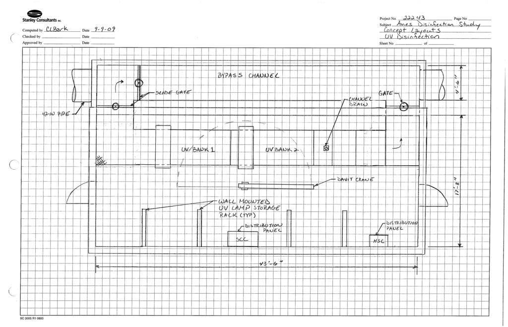
54
55
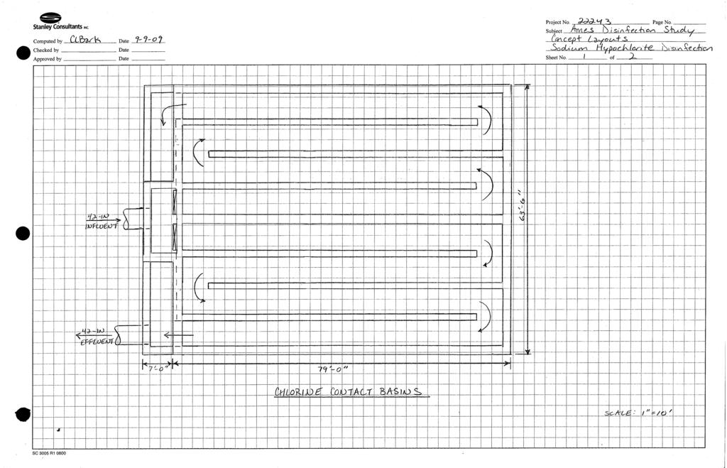
56
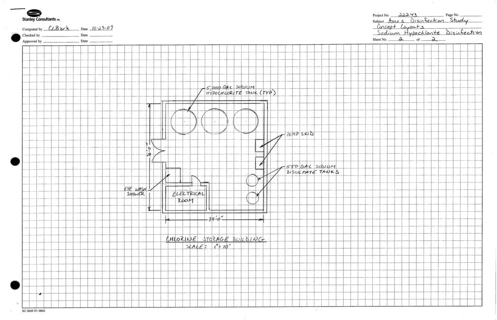
57
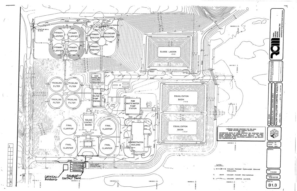
58

59
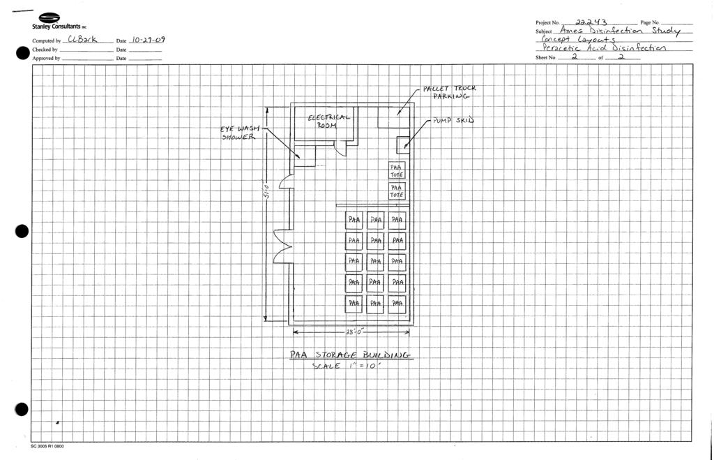
60
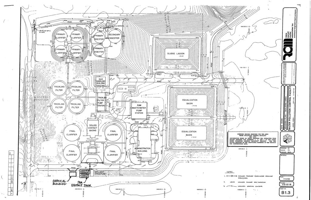
61

62
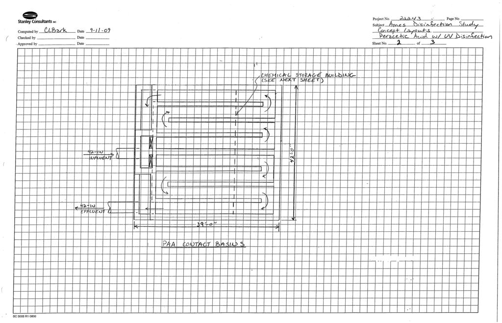
63
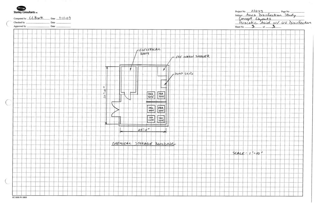
64
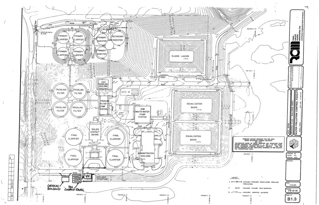
65
66 Appendix B Disinfection Technologies jmb:mjh:fs2:mp3:22243:06:04:final:disinfectionstudy B-1 Stanley Consultants
67 Disinfection Technology Summary City of Ames Disinfection Selection Workshop Handout September 1, 2009
68 This handout contains supplemental information on each disinfection method to allow a better understanding of how each system operates. Each disinfection method will contain a process description, installation photos and a process diagram. In addition, some references are included to enhance the understanding of each disinfection system. Table 3-1 describes attributes of specific disinfection methods such as chlorine gas, sodium hypochlorite, UV and ozone. The listed attributes include: Water Quality: Protect Public Health Operator Safety Process Reliability Resiliency Supply Chain Reliability Community Safety and Security Customer Support Aesthetics Environmental Impacts Table 3-2 lists the chemical and supply delivery requirements for a typical 10-mgd wastewater treatment facility for chlorine gas, sodium hypochlorite, UV and ozone systems. The disinfection methods in this handout include: Sodium Hypochlorite Chlorine Gas Chlorine Dioxide Peracetic Acid UV Light Ozone The supplemental information was sourced from the following references: AWWA. Selecting Disinfectants in a Security-Conscious Environment. American Water Works Association. USA EPA. Wastewater Technology Fact Sheets. September Lenntech. Disinfectants
69 City of Ames Disinfection Selection Workshop Sodium Hypochlorite September 1, 2009 Sodium Hypochlorite Background Information Sodium hypochlorite (NaOCl) is used on a large scale for surface purification, bleaching, odor removal and water disinfection. When used for water disinfection, the bleaching agent has a sodium hypochlorite concentration between percent. Solutions less than 40 percent are classified as a moderate oxidizing hazard (NFPA 430, 2000). Sodium hypochlorite is a corrosive substance and splashes can cause burns and eye damage. The solution must have a ph of around to remain stable and maximize its shelf-life. Sodium hypochlorite should be stored in a dry, dark and cool area for not more than one month. Sodium hypochlorite should also not come in contact with metals, air, heat and sunlight. Equipment life is usually between 5-10 years. Offgassing is possible. Only authorized and trained personnel should handle sodium hypochlorite and safety gear including chemical apron, goggles, face shield, and suitable repertory protection should be used at all times. Chemistry When sodium hypochlorite dissolves in water, two substances form, which play a role in oxidation and disinfection: hypochlorous acid and the less active hypochlorite ion. NaOCl + H 2 O => OCl - + HOCl Hydrochlorous acid is divided into hydrochloric acid (HCl) and oxygen (O). The oxygen atom is a very strong oxidator. HOCl => HCl + O Sodium Hypochlorite Generation Sodium hypochlorite can be generated on site, but is more commonly shipped by truck in containers ranging from 55 to 5,000 gallons. Sodium hypochlorite can be produced in two ways. First, it can be created by dissolving salt in softened water, which results in a concentrated brine solution. The solution is electrolyzed and forms a sodium hypochlorite solution in water. During this reaction the explosive hydrogen gas is also formed. Second, it can be created by adding chlorine gas (Cl 2 ) to caustic soda (NaOH) producing sodium hypochlorite, water and salt (NaCl). Operation, Maintenance and Equipment Bulk sodium hypochlorite solution is diluted with water in a mixing/holding tank. The diluted solution is injected by a chemical pump into the wastewater supply pipe at a controlled rate. Sodium bisulfate is typically used for the dechlorination process and is operated in the same manner as the sodium hypochlorite solution.
70 City of Ames Disinfection Selection Workshop Sodium Hypochlorite September 1, 2009 The maintenance required for a sodium hypochlorite disinfection system typically requires 3 hours per week for an 8 mgd plant. Maintenance may include routine pump and motor inspection and an assessment of the storage tanks and tubing for leaks. The following equipment is typically included in a liquid chlorination system: Sodium Hypochlorite (NaOCl) Tank(s) NaOCl Transfer Pumps NaOCl Dosing Pumps Calibration Columns Sodium Bisulfate (NaHSO 4 ) Tank(s) NaHSO 4 Transfer Pumps NaHSO 4 Dosing Pumps Chlorine Injector Sodium Bisulfate Injector Chlorine Contact Basin/Mixing Chamber Consumable Costs Bulk Sodium Hypochlorite = $0.95/gal Bulk Sodium Bisulfate = $0.24/gal Advantages Applicability: Free chlorine can be used for disinfection to meet NPDES bacterial limits. Also effective for disinfection of viruses. Free chlorine also provides disinfection residual for ancillary WWTP uses. Process Reliability: Well-established and proven disinfection practice. Water Quality: Oxidizes sulfides and reduces odors. Cost Implications: If purchase, low O&M requirements and low to moderate capital cost. If generated on-site, salt prices are more stable than those for hypochlorite. Process Reliability: Stable solution under most conditions when handled properly. Relatively simple system. If generated on-site, only outside product required for chlorine generation is salt, which can be stockpiled on-site. Community Safety/Security: If generated on-site, salt is safer to handle then purchased bulk hypochlorite if low concentration (0.8%) system is used.
71 City of Ames Disinfection Selection Workshop Sodium Hypochlorite September 1, 2009 Disadvantages Applicability: NPDES discharge limits require dechlorination. Process Reliability: Dechlorination requires a second chemical system increasing O&M and process control requirements. Water Quality: DBPs are formed including TTHMs and HAAs. Cost Implications: Contact basin required. If purchased, a large area is required for storage. If generated on-site, the O&M requirements, electric power consumption and capital costs are higher. Process Reliability: If purchased, the bulk chemical strength degrades over time, especially at high temperatures or from exposure to light. Pumping and feed systems can clog because of crystallization and improper venting. It is an extremely aggressive solution. If generated on-site, the system has several mechanical components, and in many cases, service contracts are utilized to keep systems functional. Community Safety/Security: Potential for explosive conditions within facility. If generated onsite, the release of hydrogen gas and potential gas entrapment may occur which may cause explosions within process equipment.


72 City of Ames Disinfection Selection Workshop Sodium Hypochlorite September 1, 2009 Installation Photos Sodium Hypochlorite Generation Sodium Hypochlorite Storage and Feed System Omaha WWTP


73 City of Ames Disinfection Selection Workshop Sodium Hypochlorite September 1, 2009 Sodium Bisulfate Storage and Feed System Omaha WWTP Chlorine Contact Basin Omaha WWTP Process Diagrams
74
75 City of Ames Disinfection Selection Workshop Chlorine Gas September 1, 2009 Chlorine Gas Background Information Chlorine gas, also known as elemental chlorine, is a powerful oxidizing and disinfecting agent that is either transported or generated on-site and stored as a liquefied gas under pressure. Chlorine gas is very effective for removing almost all microbial pathogens and is appropriate as both a primary and secondary disinfectant, but it is a dangerous gas that is lethal at concentrations as low as 0.1 percent air by volume. Chemistry When chlorine gas dissolves in water, two substances form, which play a role in oxidation and disinfection: hypochlorous acid and hydrochloric acid. Cl 2(g) + H 2 O = HOCl + HCl Hydrochlorous acid is divided into hydrochloric acid (HCl) and oxygen (O). The oxygen atom is a very strong oxidator. HOCl => HCl + O Chlorine Gas Generation Chlorine gas can either be delivered or generated on-site. The chlorine generator makes chlorine gas from ordinary salt (NaCl). The salt mixes with water to make a brine solution. The electric current from the power supply passes through the brine solution and separates the chloride from the sodium making chlorine. The chlorine bubbles up through the brine tank where the gas is then injected into the effluent. Operation, Maintenance and Equipment The chlorine generating system, chlorinator, features a pressure-vacuum regulating valve to reduce the supply pressure of the chlorine gas to a negative (vacuum) level. The gas flow through the chlorinator can be fine-tuned by adjustment of a metering orifice, which is in-line with a vacuum differential regulating valve. Gas flow from the chlorinator passes into an injector, where it is mixed with an outside supply of water or treated wastewater. The chlorine mixture is then pumped through a diffuser mechanism into the influent to the chlorine contact chamber. Sodium bisulfate or sulfur dioxide is typically used for the dechlorination process. Bulk chemical solution is diluted with water in a mixing/holding tank. The diluted solution is injected by a chemical pump into the wastewater supply pipe at a controlled rate.
76 City of Ames Disinfection Selection Workshop Chlorine Gas September 1, 2009 The maintenance required for a gas chlorination system typically requires 2 hours per week for an 8 mgd plant. Maintenance may include routine pump and motor inspection and an assessment of the storage tanks and tubing for leaks. The following equipment is typically included in a gas chlorination system: Compressed Chlorine Gas Storage (purchased) Salt Storage (generated on-site) Chlorine Evaporator Chlorinator Chlorine Injector Chlorine Diffuser Liquefied Sulfur Dioxide/Sodium Bisulfate (Dechlorination) Storage Dechlorination Transfer Pumps Dechlorination Dosing Pumps Dechlorination Evaporator Sulfonator (if using sulfur dioxide) Dechlorination Injector Dechlorination Diffuser Contact Basin/Mixing Chamber Consumable Costs Bulk Chlorine = $0.30/lb Bulk Sodium Bisulfate = $0.24/gal Bulk Sulfur Dioxide = $0.50/lb Advantages Applicability: Free chlorine can be used for disinfection to meet NPDES bacterial limits. Also effective for disinfection of viruses. Free chlorine also provides disinfection residual for ancillary WWTP uses. Process Reliability: Well-established and proven disinfection practice. Water Quality: Oxidizes sulfides and reduces odors. Cost Implications: Low to moderate capital cost and low chemical costs. Process Reliability: Simple and dependable disinfection method. Community Safety/Security: none
77 City of Ames Disinfection Selection Workshop Chlorine Gas September 1, 2009 Disadvantages Applicability: NPDES discharge limits require dechlorination. Process Reliability: Dechlorination requires a second chemical system increasing O&M and process control requirements. Water Quality: DBPs are formed including TTHMs and HAAs. Cost Implications: Contact basin required. Process Reliability: none Community Safety/Security: Safety and security concerns for both on-site storage and transportation/delivery must be addressed.


78 City of Ames Disinfection Selection Workshop Chlorine Gas September 1, 2009 Installation Photos Chlorine Gas Dosing Chlorine Injection Network
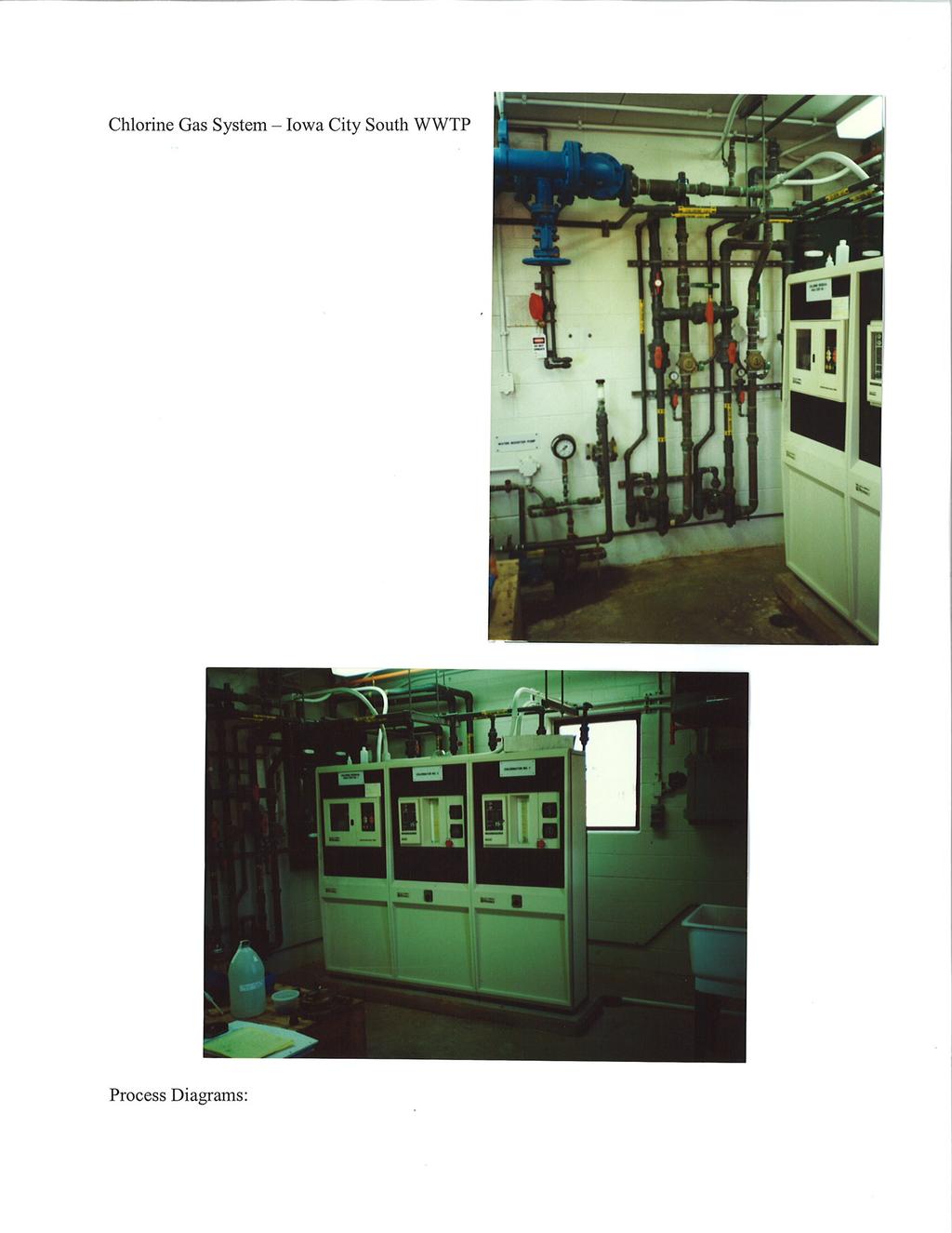
79
80
81 City of Ames Disinfection Selection Workshop Chlorine Dioxide September 1, 2009 Chlorine Dioxide Background Information Chlorine dioxide (ClO 2 ) is mainly used as a bleach. As a disinfectant it is effective even at low concentrations because of its unique qualities. Chlorine dioxide is a small, volatile and very strong molecule. In diluted, watery solutions chlorine dioxide is a free radical and at high concentrations it reacts strongly with reducing agents. It is an unstable gas that dissociates into chlorine gas, oxygen gas and heat. Chlorine dioxide s oxidation strength is not as high as ozone or hypochlorous acid, but it has a high oxidation capacity. It will only react with sulphuric substances, amines and some other reactive organic substances. When in contact with viruses and pathogens, the chlorine dioxide will react with the cell membranes and break apart their RNA and amino acids to prevent protein formation. As a result, chlorine dioxide is more effective against viruses than chlorine and ozone. Since chlorine dioxide has such a high oxidation capacity, only a low dose is required to disinfect the treated wastewater. The required concentration dose as well as contact time required for adequate disinfection is less than the requirements for sodium hypochlorite, thus having a smaller footprint. Chloride dioxide is unstable when in contact with sunlight, but its disinfection capacity is not compromised by the water s ph, temperature and alkalinity. Chemistry Chlorine dioxide must be generated on-site due to its explosive nature, instability and short shelflife. Chlorine dioxide can be generated by combining hydrochloric acid (HCl) or chlorine with sodium chlorite (NaClO 2 ). 2NaClO 2 + Cl 2 => 2ClO 2 + 2NaCl or 5NaClO 2 + 4HCl => 4ClO 2 + 5NaCl + 2H 2 O Chlorine dioxide can also be formed by combining sodium chlorite, sodium hypochlorite (NaOCl) and hydrochloric acid. HCl + NaOCl + 2NaClO 2 => 2ClO 2 + 2NaCl + NaOH Chlorine is used more often with sodium chlorite because a greater amount of chlorine dioxide is generated in comparison to the other chemical reactions. Chlorine Dioxide Generation The conventional chlorine-chlorite solution method generates chlorine dioxide in a two-step process. First, chlorine gas is reacted with water to form hypochlorous acid (HOCl) and hydrochloric acid (HCl). These acids then react with sodium chlorite (NaClO 2 ) to form chlorine dioxide (ClO 2 ). The ratio of sodium chlorite to hypochlorous acid should be carefully controlled. Insufficient chlorine feed will result in a large amount of unreacted chlorite. Excess chlorine feed may result in the formation of chlorate ion, which is an oxidation product of chlorine dioxide and not currently regulated.
82 City of Ames Disinfection Selection Workshop Chlorine Dioxide September 1, 2009 Operation, Maintenance and Equipment The equipment necessary for chlorine dioxide generation typically consists of a chlorine dioxide generator with PLC control, a flow sensor, a chemical pumping system, and chlorine dioxide and oxidation-reduction potential electrodes. If a flow pace system is used, no system operation is required; all chemical dosages fluctuate based on the measured flow. Sodium bisulfate is typically used for the dechlorination process. Bulk chemical solution is diluted with water in a mixing/holding tank. The diluted solution is injected by a chemical pump into the wastewater supply pipe at a controlled rate. The maintenance required for a chlorine dioxide system typically requires 1 hour per week according to DuPont representatives. Maintenance may include routine pump and motor inspection, an assessment of the storage tanks and tubing for leaks, and an assessment test. The following equipment is typically included in a chlorine dioxide system: Sodium Chlorite Storage Tank(s) Sodium Chlorite Transfer Pump Sodium Chlorite Dosing Pump Chlorine Storage Tank(s) Chlorine Evaporator Chlorinator Chlorine Dioxide Generator w/ PLC Control Chlorine Dioxide Transfer Pump Chlorine Dioxide Dosing Pump Calibration Column Chlorine Dioxide Injector Chlorine Dioxide Injector Sodium Bisulfate (NaHSO 4 ) Tank(s) NaHSO 4 Transfer Pumps NaHSO 4 Dosing Pumps Sodium Bisulfate Injector Contact Basin/Mixing Chamber Consumable Costs Bulk Chlorine = $0.30/lb Bulk Sodium Bisulfate = $0.24/gal Bulk Sodium Chlorite = $/lb Advantages Applicability: Free chlorine can be used for disinfection to meet NPDES bacterial limits.

83 City of Ames Disinfection Selection Workshop Chlorine Dioxide September 1, 2009 Also effective for disinfection of viruses. Free chlorine also provides disinfection residual for ancillary WWTP uses. Process Reliability: Well-established and proven disinfection practice. Water Quality: Reduces odors and controls iron, manganese, hydrogen sulfide, and phenolic compounds. DBPs are not formed. Cost Implications: none Process Reliability: Easy to generate and dependable disinfection method. Community Safety/Security: none Disadvantages Applicability: NPDES discharge limits require dechlorination. Process Reliability: Dechlorination requires an additional chemical system increasing O&M and process control requirements. Water Quality: Chlorite and chlorate byproducts are formed. Cost Implications: Costs associated with training, sampling, and laboratory testing for chlorite and chlorate are high. The cost of the sodium chlorite is high. Contact basin required. Process Reliability: none Community Safety/Security: Safety and security concerns for both on-site chemical storage and transportation/delivery must be addressed. Installation Photos Chlorine Dioxide Disinfection Water Treatment Device


84 City of Ames Disinfection Selection Workshop Chlorine Dioxide September 1, 2009 Chlorine Dioxide Generators 3-in Flow Pace Chlorine Dioxide Generator by DuPont Process Diagram
85
86 City of Ames Disinfection Selection Workshop - Peracetic Acid September 1, 2009 Peracetic Acid Background Information Peracetic acid (C 2 H 4 O 3 ) is a mixture of acetic acid (CH 3 COOH) and hydrogen peroxide (H 2 O 2 ) in a watery solution. It can also be produced by oxidation of acetaldehyde (CH 3 CHO). Peracetic acid is usually produced in concentrations of 5-15%. Peracetic acid degradation products are non-toxic and can easily dissolve in water. It is a very powerful oxidant; the oxidation potential outranges that of chlorine and chlorine dioxide resulting in a shorter contact time. Peractic acid, as a disinfectant, oxidizes the outer cell membrane of microorganisms causing the microorganism to be deactivated rapidly. Peracetic acid can deactivate a large variety of pathogenic microorganisms, viruses and spores. Chemistry When peracetic acid dissolves in water, it disintegrates into hydrogen peroxide and acetic acid. C 2 H 4 O 3 + H 2 O => CH 3 COOH + H 2 O 2 The hydrogen peroxide and acetic acid then break apart into water, oxygen and carbon dioxide. C 2 H 4 O 3 + H 2 O => O 2 + CO 2 + H 2 O Peracetic Acid Generation Peracetic acid is not a common method of disinfection. Only a couple facilities in the United States produce peracetic acid and the nearest facility is in Joliet, IL. The only method of delivery is by 55 gallon drums or 300 gallon totes. Peracetic acid cannot be generated on-site. Operation, Maintenance and Equipment A peracetic acid system is similar to a sodium hypochlorite system. Bulk peracetic acid solution is diluted with water in a mixing/holding tank. The diluted solution is injected by a chemical pump into the wastewater supply pipe at a controlled rate. The maintenance required for a peracetic acid disinfection system typically requires less time than a sodium hypochlorite system (< 3 hours) since a dechlorination system is not required. Maintenance may include routine pump and motor inspection and an assessment of the storage tanks and tubing for leaks. The following equipment is typically included in a parecetic acid system: Parecetic Acid (PAA) Tank(s) PAA Transfer Pumps PAA Dosing Pumps
87 City of Ames Disinfection Selection Workshop - Peracetic Acid September 1, 2009 Calibration Columns PAA Injector Contact Basin/Mixing Chamber Consumable Costs Bulk Peracetic Acid = $12.96/gal ($1.37/lb) Advantages Applicability: Provide residual protection to meet NPDES bacterial limits. Also effective for disinfection of viruses. Process Reliability: Proven disinfection practice. Water Quality: Reduces odors. No DBPs are formed. Cost Implications: No purchase of dechlorination equipment. Smaller contact basin than other chlorine disinfection methods. Process Reliability: Stable solution under most conditions when handled properly. Relatively simple system. Community Safety/Security: Stable and non-corrosive chemical. Disadvantages Applicability: Cannot be used for ancillary WWTP uses such as algae control. A form of chlorine required for these ancillary purposes. Process Reliability: Disinfection process affected by ph and temperature. Water Quality: none Cost Implications: Contact basin required. Cost of peracetic acid is high due to few production facilities in US. Process Reliability: none Community Safety/Security: Increase in organic content and potential of microbial growth in the effluent due to the formation of acetic acid. Refer to the photos and the process diagrams of the sodium hypochlorite system for reference.
88 City of Ames Disinfection Selection Workshop UV Light September 1, 2009 Ultraviolet (UV) Light Background Information An ultraviolet light (UV) disinfection system is a physical process that transfers electromagnetic energy from a mercury arc lamp to an organism s genetic material. When UV radiation penetrates the cell wall of an organism, it destroys the cell s ability to reproduce by structurally altering the DNA molecule. UV light also alters virus RNA. The germicidal effectiveness of UV is optimum at the 250 to 270 nm wavelength, which is the maximum absorption by nucleic acids. The effectiveness of a UV disinfection system depends on the characteristics of the wastewater, the intensity of UV radiation, the amount of time the microorganisms are exposed to the radiation, and the reactor configuration. Disinfection success is directly related to the concentration of colloidal and particulate constituents in the wastewater. Lamp assemblies may be installed within enclosed reactors or within open channels. The current configurations acceptable for UV disinfection equipment include contact systems with submerged UV lamps enclosed in quartz tubes called sleeves that are placed parallel to channel flow (horizontal), or placed perpendicular to flow (vertical). The source of UV radiation is either the low-pressure or mediumpressure mercury arc lamp with low or high intensities. Chemistry/Generation N/A Operation, Maintenance and Equipment The main components of a UV disinfection system are mercury arc lamps, a reactor, and ballasts. A UV system operates automatically, and typically requires 1 hour per week of maintenance. Submerged quartz tubes must be routinely removed and cleaned of surface deposits of metal salts and absorbed organics that block UV transmission. Cleaning consists of dipping the quartz tubes in a low strength acid and wiping them down. Most UV systems have the option of installing an automatic wiper that will mechanically clean the quartz tubes on regular intervals. This does not eliminate the need to clean them by hand but it significantly reduces the frequency. Manufacturers recommend that the lamps be removed from the channels during the disinfection off season to prevent moisture and ice buildup around the equipment. Lamp and ballast replacement is necessary every year to maintain adequate UV intensity. Consumable Costs (est. for 8 mgd plant) Lamps = 42 lamps x $220/lamp = $9,240/year
89 City of Ames Disinfection Selection Workshop UV Light September 1, 2009 Advantages Applicability: Excellent disinfectant against bacteria. UV can be used for disinfectant to meet NPDES bacterial limits. Process Reliability: Disinfection efficiency not affected by ph or temperature. Water Quality: Strong disinfectant, with no known DBP formation at disinfection does. Excellent disinfectant against bacteria, pathogens, and most viruses. Cost Implications: Relatively low O&M requirements. Low space requirements. Community Safety/Security: Does not require the use of chemicals; also minimizes truck traffic for chemical deliveries. Disadvantages Applicability: Cannot be used for ancillary WWTP uses such as algae control. A form of chlorine required for these ancillary purposes. Process Reliability: Optimization of upstream treatment will improve UV effectiveness, but for lower-quality wastewaters, filtration may be necessary for UV to be effective. Water Quality: none Cost Implications: Capital cost for UV disinfection may be higher than for chlorine options. UV equipment must fit into plant s hydraulic profile; may require additional pumping. Electrical use is high and may require modifications to plant power service. Community Safety/Security: UV lamps contain mercury, so provisions for lamp recycling and emergency response are necessary.


90 City of Ames Disinfection Selection Workshop UV Light September 1, 2009 Installation Photos Vertical UV Disinfection Setup Horizontal UV Disinfection Setup Process Diagram
91
92 City of Ames Disinfection Selection Workshop Ozone September 1, 2009 Ozone Background Information Ozone is produced when oxygen (O 2 ) molecules are dissociated by an energy source into oxygen atoms and subsequently collide with an oxygen molecule to form an unstable gas, ozone (O 3 ), which is used to disinfect wastewater. Ozone must be generated onsite because it is unstable and decomposes to elemental oxygen in a short amount of time. Ozone is a very strong oxidant and virucide. The free radicals formed have great oxidizing capacity and play an active role in the disinfection process as well. When in contact with a microorganism, these free radicals destroy the cell wall of the microorganism and damage its nucleic acids. The effectiveness of ozone disinfection depends on the susceptibility of the target organisms, the contact time, and the concentration of the ozone. Chemistry Most wastewater treatment plants generate ozone by imposing a high voltage alternating current (6 to 20 kv) across a dielectric discharge gap that contains an oxygen-bearing gas. 2O 2 + [6-20 kv] => O* + O 3 When ozone decomposes in water, the free radicals hydrogen peroxy (HO 2 ) and hydroxyl (OH) are formed. O 3 + H 2 O => HO 2 + OH - Ozone Generation The electrical discharge method is the most common energy source used to produce ozone. Extremely dry air or pure oxygen is exposed to a controlled, uniform high-voltage discharge at a high or low frequency. The dew point of the feed gas must be -76 degrees Fahrenheit or lower. The gas stream generated from air will contain about 0.5 to 3.0% ozone by weight, whereas pure oxygen will form approximately two to four times that concentration. Operation, Maintenance and Equipment The components of an ozone system include feed-gas preparation, ozone generation, ozone contacting, and ozone destruction. After generation, ozone is fed into a down-flow contact chamber containing the wastewater to be disinfected. The main purpose of the contactor is to transfer ozone from the gas bubble into the bulk liquid while providing sufficient contact time for disinfection. Because ozone is quickly consumed, it must be contacted uniformly in a near plug flow contactor. The off-gases from the contact chamber must be treated to destroy any remaining ozone before release into the atmosphere.
93 City of Ames Disinfection Selection Workshop Ozone September 1, 2009 Ozone disinfection does require higher maintenance and operator skill than most disinfection methods. It is a relatively complex system so outside support may be required when it is not operating efficiently. The following equipment is typically included in an ozone system: Refrigerant Cooler Desiccant Drier Ozone Generator Cooling Water Compressors Water Cooled Heat Exchanger Ozone Contactor Consumable Costs Unknown at this time. Advantages Applicability: Excellent disinfectant against bacteria. Ozone can be used for disinfectant to meet NPDES bacterial limits. Process Reliability: none Water Quality: Strong disinfectant that does not form TTHMs and HAAs. Provides excellent disinfection of viruses and other pathogens. Oxidizes sulfides and reduces odors. Strong oxidant that destroys many CECs. Cost Implications: none Community Safety/Security: none Disadvantages Applicability: Short-lived residual not feasible for ancillary WWTP uses. Systems for disinfection will necessitate regular monitoring of ozone residual. Process Reliability: Optimization of upstream treatment will improve UV effectiveness, but for lower-quality wastewaters, filtration may be necessary for UV to be effective. Optimization of upstream treatment will reduce ozone demand, but filtration may be necessary for ozone to be effective. Relatively complex. Water Quality: Reacts with bromide to form the DBP bromated. Bromate formation increases with increasing bromide concentration and increasing ozone dosage. Cost Implications: Capital cost may be higher than other disinfection options. Filtration

94 City of Ames Disinfection Selection Workshop Ozone September 1, 2009 upstream of ozone may be necessary to reduce ozone demand and ensure process effectiveness. Contact basin must fit into plant s hydraulic profile; may require additional pumping. Electrical use is high and may require modifications to plant power service. Community Safety/Security: Produces off-gas containing ozone that is a safety hazard and must be destroyed before release to the atmosphere. Can require storage and transport of hazardous compressed oxygen on-site. Installation Photos Ozone Generator


95 City of Ames Disinfection Selection Workshop Ozone September 1, 2009 Ozone Disinfection at a Wastewater Plant Standard skid mounted PDA / PDO ozone systems Process Diagram
Module 5: Disinfection and Chlorination Answer Key
 Module 5: Disinfection and Chlorination Answer Key What processes in wastewater treatment serve to remove pathogens? See Table at top of page 1-3. Exercise for Unit 1 Disinfection and Chlorination Principles
Facilities Plan. Technical Memorandum Nos. TM-CSO-11 and TM-WW-5 Disinfection Facilities
 City of St. Joseph, Missouri Technical Memorandum Nos. TM-CSO-11 and TM-WW-5 Disinfection Facilities By Work Order No. 09-001 B&V Project 163509 July 31, 2009 Technical Memorandum Nos. TM-CSO-11/TM-WW-5
City of Ames. Water Pollution Control. Long Range Facility Plan
 City of Ames Water Pollution Control Long Range Facility Plan Introduction Over 25 years ago, the City of Ames last completed a Wastewater Facility Plan. That Facility Plan prompted design and construction
Anderson Water Pollution Control Plant
 City of Anderson Wastewater Division Public Works Director Jeff Kiser Chief Plant Operator Plant Supervisor Operator III Operator I Phil DeBlasio Mike Hansen Tony Hinchliff Vacant Collections Supervisor
11.0 EFFLUENT DISINFECTION
 SEWPCC Upgrading/Expansion Conceptual Design Report SECTION 11 - Table of Contents 11.0 EFFLUENT DISINFECTION...11.1 11.1 PURPOSE OF UNIT PROCESS...11.1 11.2 EXISTING DISINFECTION FACILITY...11.2 11.2.1
CITY OF STEUBENVILLE, OHIO WASTEWATER TREATMENT FACILITY
 CITY OF STEUBENVILLE, OHIO WASTEWATER TREATMENT FACILITY PAA Pilot Demonstration to determine PAA Efficacy as an alternative disinfectant to Chlorine and Sodium Bisulfite technology for wastewater Authors
Palmer Wastewater Treatment Plant Environmental Impacts. A summary of the impacts of this treatment alternative are listed below:
 6.1.3 Environmental Impacts A summary of the impacts of this treatment alternative are listed below: 1. The Matanuska River will receive treated effluent as it currently does. 2. Effluent quality would
Northfield Township WWTP Capacity Evaluation Report
 Northfield Township WWTP Capacity Evaluation Report March 18, 2015 PRESENTED TO PRESENTED BY Northfield Township 8350 Main Street Suite A Whitmore Lake, Michigan 48189 Tetra Tech 710 Avis Drive Suite 100
Facilities Plan. Technical Memorandum No. TM-WW-7 Hydraulic Analysis and Effluent Pump Station
 City of St. Joseph, Missouri Hydraulic Analysis and Effluent Pump Station By Work Order No. 09-001 B&V Project 163509 May 20, 2010 Table of Contents 1.0 Executive Summary...1 2.0 Purpose of Study...2 3.0
NC-PC Industry Day Pretreatment 101. Industrial Waste Impacts on POTW Treatment Processes. Dawn Padgett Operations Manager Charlotte Water
 NC-PC Industry Day Pretreatment 101 Industrial Waste Impacts on POTW Treatment Processes Dawn Padgett Operations Manager Charlotte Water NC-PC Industry Day Definitions BOD Amount of oxygen consumed by
VC Series Wastewater. Vertical Open Channel Ultraviolet Disinfection
 VC Series Wastewater Vertical Open Channel Ultraviolet Disinfection VC Series dour Company Glasco has been manufacturing UV disinfection systems for over 50 years. Equipment is manufactured for a variety
Environmental Improvements Associated with Springfield WWTP EHRT. Using the Compressed Media Filter Technology
 Environmental Improvements Associated with Springfield WWTP EHRT Tuesday, June 23 9:30 am Using the Compressed Media Filter Technology WWETCO WWETCO FlexFilter ENGINEERS CLUB OF ST. LOUIS Performance Testing
Chlorination/Dechlorination: An Environmental Solution
 Chlorination/Dechlorination: An Environmental Solution Presented at the 1996 IBC USA Conferences by GERALD F. CONNELL, Capital Controls Company, Inc., Colmar, PA SUMMARY: The topic of this presentation
Wedeco s iduron INTELLIGENT SOLUTION FOR WASTEWATER DISINFECTION NEEDS
 Wedeco s iduron INTELLIGENT SOLUTION FOR WASTEWATER DISINFECTION NEEDS First, let s have a closer Look: Wedeco Production and Services in Herford 1976 Revenues 2017: 127 Mio.$ Employees: 250 Leading global
Copies: Mark Hildebrand (NCA) ARCADIS Project No.: April 10, Task A 3100
 ARCADIS Project No.: April 10, Task A 3100") MEMO To: Jeff Pelz (West Yost) Kathryn Gies (West Yost) Copies: Mark Hildebrand (NCA) ARCADIS U.S., Inc. 200 Harvard Mills Square Suite 430 Wakefield Massachusetts 01880 Tel 781 224 4488 Fax 781 224 3033
MEMO To: Jeff Pelz (West Yost) Kathryn Gies (West Yost) Copies: Mark Hildebrand (NCA) ARCADIS U.S., Inc. 200 Harvard Mills Square Suite 430 Wakefield Massachusetts 01880 Tel 781 224 4488 Fax 781 224 3033
Wastewater Treatment Works... The Basics
 United States EPA 833-F-98-002 Environmental Protection May 1998 Agency Office of Water (4204) Wastewater Treatment Works... The Basics O ne of the most common forms of pollution control in the United
TABLE OF CONTENTS. SECTION 1 INTRODUCTION 1.1 Background Purpose and Scope
 TABLE OF CONTENTS Page EXECUTIVE SUMMARY... ES-1 SECTION 1 INTRODUCTION 1.1 Background... 1-1 1.2 Purpose and Scope... 1-2 SECTION 2 HYDRAULIC AND PROCESS ASSESSMENT 2.1 Data Gathering and Analysis...
Where does drinking water come from?
 Water Quality Where does drinking water come from? When you think about where your drinking water comes from, it's important to consider not just the part of the river or lake that you can see, but the
2017 Annual Performance Report
 Newcastle Water Pollution Control Plant The Regional Municipality of Durham Newcastle Water Pollution Control Plant Environmental Compliance Approval (ECA): 3-2189-87-946 Dated July 26, 1994 Amendments:
Non Contact UV System at the Yakima Regional WWTP
 Installation of a Flow Through- Non Contact UV System at the Yakima Regional WWTP Sean Goris, P.E. Engineering Manager September 15, 2009 Yakima Treatment Facility Background Secondary treatment facility
Duffin Creek Water Pollution Control Plant Technical Information
 Duffin Creek Water Pollution Control Plant Technical Information Plant History The Duffin Creek Water Pollution Control Plant (WPCP) is located on the northern shore of Lake Ontario in the City of Pickering
W O C H H O L Z R E G I O N A L W A T E R R E C L A M A T I O N F A C I L I T Y O V E R V I E W
 Facility Overview The recently upgraded and expanded Henry N. Wochholz Regional Water Reclamation Facility (WRWRF) treats domestic wastewater generated from the Yucaipa-Calimesa service area. The WRWRF
ULTRAVIOLET DISINFECTION 2013 Municipal Markets.
 ULTRAVIOLET DISINFECTION 2013 Municipal Markets www.glascouv.com Glasco Timeline 1940 s NYC based industrial manufacturer - pharmaceutical and food grade stainless steel fabricator 1960 s - Added Industrial
WASTEWATER TREATMENT PLANT MASTER PLAN 6. BUSINESS CASE EVALUATION OF ALTERNATIVES
 WASTEWATER TREATMENT PLANT MASTER PLAN 6. BUSINESS CASE EVALUATION OF ALTERNATIVES A range of potential ammonia limits were identified for alternatives evaluation, as discussed in Section 2.2.5. This chapter
THE BOSSIER CITY WATER TREATMENT PLANT (Background and Current Process Layout )
") THE BOSSIER CITY WATER TREATMENT PLANT (Background and Current Process Layout - 2018) PLANT HISTORY The Bossier City Water Treatment Plant was built in 1958. The original plant had a treatment capacity
THE BOSSIER CITY WATER TREATMENT PLANT (Background and Current Process Layout - 2018) PLANT HISTORY The Bossier City Water Treatment Plant was built in 1958. The original plant had a treatment capacity
Wastewater Treatment Processes
 Wastewater Treatment Processes (Sep 27 th and 28 th, 2016) by Dr. Arun Kumar (arunku@civil.iitd.ac.in) Objective: To learn about processes used in tertiary treatment Courtesy: Dr. Irene Xagoraraki, MSU,
UV Wastewater. Vertical Open Channel Ultraviolet Disinfection
 UV Wastewater Vertical Open Channel Ultraviolet Disinfection GLOW VC Series dour Company Glasco Ultraviolet has been manufacturing UV water and wastewater disinfection systems for over 50 years. We manufacture
Polishing Ponds. Biosolids Storage. Ammonia Removal. Digesters. Thickeners. Pretreatment. Final Clarifiers. Primary Clarifiers.
 Wastewater Treatment Facility (2012) Polishing Ponds Biosolids Storage Ammonia Removal Digesters Thickeners Pretreatment Primary Clarifiers Activated Sludge Final Clarifiers OVERVIEW Whenever a home, business,
American Water College 2010
 Vocabulary Disinfection Air Gap An open vertical drop, or vertical empty space, that separates a drinking (potable) water supply to be protected from another water system in a water treatment plant or
CHAPTER 4 WASTEWATER CHARACTERISTICS WASTEWATER FLOWS
 CHAPTER 4 WASTEWATER CHARACTERISTICS Wastewater collection, treatment, and disposal facilities are designed to handle specific hydraulic and pollutant loads for 20 or more years after they are constructed.
Lowering The Total Cost Of Operation
 Lowering The Total Cost Of Operation The system removes more solids than conventional clarification, so filters can run longer between backwash cycles. Fewer backwash cycles means less backwash water,
Sanitary Sewer Systems. Sewage Collection System. Types of Sewage 10/12/2016. General Overview
 Sanitary Sewer Systems General Overview Sewage Collection System Pipes Pumping stations Maintenance entry points manholes Types of Sewage Sanitary Domestic sewage: human wastes and washwater from public
75 th STREET WASTEWATER TREATMENT PLANT UPGRADES PROJECT
 75 th STREET WASTEWATER TREATMENT PLANT UPGRADES PROJECT Basis of Design Memorandum Design Memo No.: DM-7 (REVISED) Date: February 2005 Project/Task: 124487.001.420 Subject: Prepared by: Reviewed by: Hydraulic
Best Practice in Sewage and Effluent Treatment Technologies
 Best Practice in Sewage and Effluent Treatment Technologies Contents 1 Wastewater - Introduction 1 1.1 Earth s ecological system 1 1.1.1 Water effect on ecology 2 1.1.2 Wastewater generation 3 1.2 Wastewater
Wastewater Treatment Technology and Applications in Industrial Facilities
 Wastewater Treatment Technology and Applications in Industrial Facilities Treatment that industrial facilities give wastewater before discharging it to the local wastewater treatment facility is referred
UV Disinfection for a Municipal Wastewater Lagoon Effluent No Prior Filtration Needed? Wayne Wong, M.A.Sc., P.Eng., PMP
 UV Disinfection for a Municipal Wastewater Lagoon Effluent No Prior Filtration Needed? Wayne Wong, M.A.Sc., P.Eng., PMP Acknowledgements 2 Northern Rockies Regional Municipality Northern Rockies Engineering
Your Water Treatment Technology Partners for Wash Water & Industrial Water Treatment. Design Supply Integration Installation Maintenance
 Your Water Treatment Technology Partners for Wash Water & Industrial Water Treatment Design Supply Integration Installation Maintenance The Challenge for Businesses that Use Water PUBLIC HEALTH EPA state
Domestic Waste Water (Sewage): Collection, Treatment & Disposal
: Collection, Treatment & Disposal") Domestic Waste Water (Sewage): Collection, Treatment & Disposal Sanitary sewers Storm water sewers Combined sewers Types of sewers: Types of collection system Building sewer/building connections:connected
Domestic Waste Water (Sewage): Collection, Treatment & Disposal Sanitary sewers Storm water sewers Combined sewers Types of sewers: Types of collection system Building sewer/building connections:connected
Module 20: Trickling Filters Answer Key
 Module 20: Trickling Filters Answer Key Calculation Capital City WWTF, which processes 2.0 MGD, is required to nitrify to meet the 2.0 mg/l ammonia discharge limit stated in their NPDES permit. A table
Situation Normal. facilities? Can a wastewater treatment plant be retrofit for UV disinfection
 Situation Normal During a UV Disinfection Retrofit Research has proven ultraviolet (UV) disinfection to be a viable alternative to the chemical disinfection of water and wastewater. New treatment facilities
BROCKVILLE CITY OF THE 1000 ISLANDS BROCKVILLE WATER POLLUTION CONTROL CENTRE UPGRADE CLASS ENVIRONMENTAL ASSESSMENT REPORT
 BROCKVILLE CITY OF THE 1000 ISLANDS BROCKVILLE WATER POLLUTION CONTROL CENTRE UPGRADE CLASS ENVIRONMENTAL ASSESSMENT REPORT Evaluation of Effluent Disinfection Strategies Prepared By: : Evaluation of Effluent
Lagoons Operation and Management in New Brunswick
 Lagoons Operation and Management in New Brunswick Lagoons Provide secondary treatment to domestic wastewater by the action of bacteria stabilizing the organic matter in the wastewater. Benefits of lagoons:
City of Leadwood Wastewater System Engineering Report
 City of Leadwood Wastewater System Engineering Report DRAFT H2O C Engneering www.h2oc.com 877-22-WATER Background The purpose of this report is to describe the City of Leadwood s wastewater system (System
Meadowbrook-Limestone (MBLS) Wastewater Treatment Plant. Wet Weather Operating Plan
 Wastewater Treatment Plant. Wet Weather Operating Plan") Meadowbrook-Limestone (MBLS) Wastewater Treatment Plant Wet Weather Operating Plan July 2014 TABLE OF CONTENTS Section 1 Introduction and Overview. 1 Section 2 Wet Weather Operational Strategy....2 a.
Meadowbrook-Limestone (MBLS) Wastewater Treatment Plant Wet Weather Operating Plan July 2014 TABLE OF CONTENTS Section 1 Introduction and Overview. 1 Section 2 Wet Weather Operational Strategy....2 a.
ATTACHMENT 1 GENERAL FACILITY INFORMATION. BOD5 mg/l mg/l TSS mg/l mg/l NH3-N mg/l mg/l
 ATTACHMENT 1 GENERAL FACILITY INFORMATION 1. Facility Name: 2. Type of Facility: 3. Population Served: Present: Design: 4. Flow: Average Maximum Peak 5. Water Quality: Present Design Assumed Actual Source:
Appendix J Effluent Pump Station
 Appendix J Effluent Pump Station TECHNICAL MEMORANDUM Salmon Creek Treatment Plant Effluent Pump Station Hydraulics and Phasing Analysis for the Phase 5A Project Columbia River Outfall and Effluent Pipeline
HIGH RATE TREATMENT AS PART OF THE SOLUTION FOR WET WEATHER FLOWS JUNE
 City of Newark, Ohio HIGH RATE TREATMENT AS PART OF THE SOLUTION FOR WET WEATHER FLOWS JUNE 22, 2011 High Rate Treatment Tanks/UV Wet Weather Screen Building JC2/Wet Weather Pump Station Wet Weather Control
VILLAGE OF ALGONQUIN 2014 WASTEWATER FACILITY PLAN UPDATE EXECUTIVE SUMMARY
 EXECUTIVE SUMMARY EXECUTIVE SUMMARY INTRODUCTION AND BACKGROUND The Village of Algonquin, located along the Fox River in McHenry County, provides wastewater collection and treatment services to the entire
Texas A&M Wastewater Treatment Plant 9685 Whites Creek Rd., College Station, TX
 Municipal Wastewater Treatment Plant Site Visit Report Thursday, October 2, 2014 Prepared by: Elora Arana, Environmental Studies student Prepared for: Dr. Heather Wilkinson, Professor BESC 489/411 Texas
/ Marley MARPAK Modular Biomedia /
 / Marley MARPAK Modular Biomedia / The Marley MARPAK Difference SPX Cooling Technologies is a world leader in the design, manufacturing and construction of cooling products. The design and production of
Donner Summit PUD Interactive Map Pop-up Text and Photos June 30, 2015
 Donner Summit PUD Interactive Map Pop-up Text and Photos June 30, 2015 I Administration The administration building is home to DSPUD s friendly personnel. The adjacent garage provides vehicle and equipment
Utilizing ScaleBlaster to Reduce Lime Scale Build-up in an Industrial Wastewater Treatment Plant
 Utilizing ScaleBlaster to Reduce Lime Scale Build-up in an Industrial Wastewater Treatment Plant Documented by The Village of Sauget Physical/Chemical Plant May, 2015 Purpose Case Study: Utilizing ScaleBlaster
19. Rapid Disinfection Technique Using High- Concentration Ozone for Combined Sewer Overflow
 19.RapidDisinfectionTechniqueUsingHigh- Concentration for Combined Sewer Overflow. Takahashi 1, T.Kirihara 2, M.Koeda 3 Director, ChiefResearcher,Senior Researcher 3 Second Research Department Japan Institute
Executive Summary. Introduction
 Executive Summary Introduction The City of Terre Haute has developed a (CSO LTCP), which describes the measures they will take to reduce the combined sewer overflows and improve water quality in the Wabash
Blue Springs Missouri USA - 40 MGD Vertical Amalgam. Ultraviolet Disinfection. Closed Vessel, Open Channel and Fluoropolymer Tube
 Blue Springs Missouri USA - 0 MGD Vertical Amalgam Ultraviolet Disinfection Closed Vessel, Open Channel and Fluoropolymer Tube GLASCO UV dour Company GLASCO UV (NJ-USA) has continuously manufactured UV
TAMING TIGERS AND WRESTLING ANACONDAS: PENDER COUNTY COMMERCE PARK WWTP
 ABSTRACT TAMING TIGERS AND WRESTLING ANACONDAS: PENDER COUNTY COMMERCE PARK WWTP Tim Baldwin, PE, Senior Vice President McKim & Creed, Inc. Pender County s Commerce Park was created as a vehicle to attract
Wastewater treatment objecives
 Wastewater treatment objecives Removal of suspended and floatable materials Degradation of biodegradable organics Removal of nutrients Elimination of priority pollutants Elimination of pathogenic organisms
Session 311: Effects of TSS on Peracetic Acid Dosing for CSO Events
 Session 311: Effects of TSS on Peracetic Acid Dosing for CSO Events Authors: Robert Freeborn, Jacquelyn Wilson Background Peracetic acid has been used in the food and beverage industry since the 1950 s
ECO Smart Aerobic Waste Water Treatment System. Optimising the re-use and recycling of waste water
 Optimising the re-use and recycling of waste water The ECO Smart aerobic wastewater treatment system is a selfcontained wastewater treatment system that utilizes a combination of anaerobic as well as aerobic
Selection of UV Disinfection Systems for Achieving Class A Reuse Water at Small MBR plants
 Selection of UV Disinfection Systems for Achieving Class A Reuse Water at Small MBR plants Li Lei, Douglas Berschauer, Elizabeth Hill, and Tom Moore 1 Outline Introduction (UV, WWTPs) Regulations on UV
WEFTEC.06. Lake Okeechobee, Actiflo, peroxone, surface water, Cyanobacteria
 FRESH IDEAS FOR FRESH WATER: OKEECHOBEE UTILITY AUTHORITY S SURFACE WATER TREATMENT PLANT USES INNOVATIVE TECHNOLOGY TO ACHIEVE HIGH QUALITY DRINKING WATER FROM LAKE OKEECHOBEE By: Curtis Robinson, E.I.
City of Elk River Wastewater Treatment Facility Improvements. Achieving Wastewater Treatment Goals
 City of Elk River Wastewater Treatment Facility Improvements Achieving Wastewater Treatment Goals By Tejpal Bala, P.E. Bolton & Menk, Inc. The City of Elk River received a new NPDES permit and the existing
WATER AND WASTEWATER FACILITY CLASSIFICATION APPLICATION FORM
 WATER AND WASTEWATER FACILITY CLASSIFICATION APPLICATION FORM APPLICATION INSTRUCTIONS Please print or type. In keeping with the privacy provisions of the Nova Scotia Freedom of Information & Protection
ENVIRONMENTAL ENGINEERING LECTURE 3: WATER TREATMENT MISS NOR AIDA YUSOFF
 ENVIRONMENTAL ENGINEERING LECTURE 3: WATER TREATMENT MISS NOR AIDA YUSOFF LEARNING OUTCOMES Define the concept and process of water treatment. Describe the concept of coagulation, flocculation, and sedimentation
Request for Proposals
 Request for Proposals Aeration Basin Improvement Predesign and Design Project Project Number WD1401 You are hereby invited to submit a proposal for consulting services necessary to provide the City of
Minnesota Pollution Control Agency
 Minnesota Pollution Control Agency STATE OF MINNESOTA Minnesota Pollution Control Agency MUNICIPAL DIVISION PUBLIC NOTICE OF INTENT TO REISSUE NATIONAL POLLUTANT DISCHARGE ELIMINATION SYSTEM (NPDES)/ STATE
Evaluation of Cost and Benefits of CSO Treatment and Supplemental Aeration to Improve Water Quality in the Chicago Area Waterways
 Evaluation of Cost and Benefits of CSO Treatment and Supplemental Aeration to Improve Water Quality in the Chicago Area Waterways Metropolitan Water Reclamation District of Greater Chicago Research and
Facilities Plan. Volume 2 Wastewater Facilities Assessment Report Executive Summary
 City of St. Joseph, Missouri Volume 2 Wastewater Facilities Assessment Report Executive Summary By Work Order No. 09-001 B&V Project 163509 October 29, 2010 Table of Contents 1.0 Introduction...1 2.0 TM-WW-1:
EWRI Pittsburgh Section Meeting October 30, U.S. EPA, Cincinnati, OH CB&I Federal Services LLC, Cincinnati, OH
 Comparing Peracetic Acid with Sodium Hypochlorite for Disinfection of Combined Sewer Overflows Craig Patterson, P.E. 1, Don Schupp, P.E. 2, Bruce Smith, P.E. 3, Bob Freeborn 4, John Maziuk 5, Vasudevan
WEFTEC.06. ** Hatch Mott McDonald Gateway View Plaza, 1600 West Carson Street Pittsburgh, Pennsylvania. *** City of Akron Akron, Ohio
 ALTERNATIVE DISINFECTION TECHNOLOGY DEMONSTRATES ADVANTAGES FOR WET WEATHER APPLICATIONS A PILOT STUDY OF POWDERED BROMINE TECHNOLOGY Peter E. Moffa*, Daniel P. Davis*, Chris Somerlot*, Dan Sharek**, Brian
The High-Tech of a Creek. The Biofilm Technology for Large Wastewater Treatment Plants.
 The High-Tech of a Creek The Biofilm Technology for Large Wastewater Treatment Plants. Photo: Holzberger Exceptional Treatment from 4 to 5000 Inhabitants. The researchers from the Bergmann Gruppe in co-operation
Notice of Preparation
 Notice of Preparation To: From: County of Sacramento Department of Environmental Review and Assessment 827 7 th Street, Room 220 Sacramento, CA 95814 (916) 874-7914 Contact: Dennis E. Yeast Subject: Notice
SECTION 2.0 WASTEWATER TREATMENT PLANT AND DISPOSAL SYSTEM DESCRIPTION
 SECTION 2.0 WASTEWATER TREATMENT PLANT AND DISPOSAL SYSTEM DESCRIPTION Analytical Environmental Services 2-1 Jamul Indian Village Wastewater Treatment Plant Analytical Environmental Services 2-2 Jamul
Validation Studies and Beyond: Key Implementation Issues
 Review of UV Disinfection Validation Studies and Beyond: Key Implementation Issues Paul D. Swaim, P.E., CH2M HILL Denver March 8, 2011 The Burden on State Regulators Has Increased Technology-Specific EPA
UV DISINFECTION. Introduction to TrojanUV
 UV DISINFECTION Introduction to TrojanUV Applications for Ultraviolet (UV) Disinfection Disinfection of primary, secondary or tertiary wastewater effluent Disinfection of high quality wastewater for reuse
Paper 5. Sanitary Sewer Overflow Peak Excess Flow Treatment Facility Options Paper. I. State/EPA Efforts to Address Sanitary Sewer Overflows
 Oct 1999 Paper 5 Sanitary Sewer Overflow Peak Excess Flow Treatment Facility Options Paper I. State/EPA Efforts to Address Sanitary Sewer Overflows EPA estimates that one- to two-thirds of the 19,500 municipal
Brightwater: The Design Challenges of a 39 mgd (150 MLD) Membrane Bioreactor
 Membrane Bioreactor") Brightwater: The Design Challenges of a 39 mgd (150 MLD) Membrane Bioreactor J. Komorita 1, P. Burke 2, B. Youker 2, and G. Crawford 2 1 King County, 2 CH2M HILL ABSTRACT Many Membrane Bioreactor (MBR)
Brightwater: The Design Challenges of a 39 mgd (150 MLD) Membrane Bioreactor J. Komorita 1, P. Burke 2, B. Youker 2, and G. Crawford 2 1 King County, 2 CH2M HILL ABSTRACT Many Membrane Bioreactor (MBR)
Palmer Wastewater Treatment Plant 6.7 Alternative 7: Upgrade Existing Lagoons with New Percolation Bed
 6.7 Alternative 7: Upgrade Existing Lagoons with New Percolation Bed 6.7.1 Description This alternative considers expanding the capacity of the existing lagoon treatment facility and changing the discharge
CHAPTER 10 PRELIMINARY TREATMENT
 CHAPTER 10 PRELIMINARY TREATMENT TM 5-814-3/AFM 88-11, Volume III 10-1. General considerations. Preliminary treatment of wastewater includes screening, grinding, grit removal, flotation, equilization,
SMCSD Headworks, Primary and Secondary Treatment Pre-Design
 Technical Memorandum SMCSD Headworks, Primary and Secondary Treatment Pre-Design Water andenvironment Subject: Prepared For: Prepared by: Reviewed by: SMCSD Mark Takemoto, Dennis Gellerman Steve Clary
Oak Orchard Wastewater Treatment Plant. Wet Weather Operating Plan
 Oak Orchard Wastewater Treatment Plant Wet Weather Operating Plan July 2014 TABLE OF CONTENTS Section 1 Introduction and Overview. 1 Section 2 Wet Weather Operational Strategy.3 a. Wet Weather Operation
Alexandria Sewage Lagoon Treatment Facility Municipal Class C Environmental Assessment Public Information Centre #2 Welcome!
 Alexandria Sewage Lagoon Treatment Facility Municipal Class C Environmental Assessment Public Information Centre #2 Welcome! Municipal Class Environmental Assessment Status We are Here Study Overview The
Wastewater Treatment. Where does wastewater go when it leaves your house?
 Wastewater Treatment Where does wastewater go when it leaves your house? Let s s take a look The process includes: Collection of wastewater Primary Treatment Secondary Treatment Solids Handling Influent
Walter E. Deuchler Associates, Inc. Consulting Engineers
 I. DESCRIPTION OF PROJECT HIGHLIGHTS P lanning for the latest improvements to the Salt Creek Sanitary District (District) began in 2001 with the updating of the Facility Plan, which identified the need
WASTEWATER DEPARTMENT. Bentonville Wastewater Treatment Plant Facts:
 Mission: The mission of the Bentonville Wastewater Treatment Utility and staff is to protect public health and the environment through the effective treatment of wastewater. Effective wastewater treatment
AT 1500 ULTRAVIOLET DISINFECTION
 AT 1500 ULTRAVIOLET DISINFECTION the safe, effective and reliable way to disinfect in applications where ultraviolet (UV) treatment is preferred Your complete solution to meet even the most stringent environmental
Post-Aerobic Digester with Bioaugmentation Pilot Study City of Meridian, ID WWTP PNCWA 2010
 Post-Aerobic Digester with Bioaugmentation Pilot Study City of Meridian, ID WWTP by: William Leaf Adrienne Menniti Bruce Johnson CH2M HILL, Inc. Clint Dolsby Tracy Crane City of Meridian October 26, 21
Ultraviolet Light for Disinfection of Wastewater. Tom O Connor, PE H 2 O C Engineering
 UV Ultraviolet Light for Disinfection of Wastewater Tom O Connor, PE H 2 O C Engineering Solar corona as seen in deep UV light Extreme UV imaging telescope aboard Solar and Heliospheric Observatory spacecraft
Wastewater Treatment clarifier
 Wastewater Treatment Pretreatment During pretreatment, items would normally be removed that would hinder the further processes of treatment. Items commonly removed include roots, rags, cans, or other large
DW Module 23: Organic Removal Answer Key
 DW Module 23: Organic Removal Answer Key EXERCISE UNIT 1: Use the Word Box above to complete questions. Words used twice are indicated with a (2). Word Box Air Stripping (2) Adsorption (2) Boiling Carbon
UV DISINFECTION OF LOW TRANSMITTANCE PHARMACEUTICAL WASTEWATER
 UV DISINFECTION OF LOW TRANSMITTANCE PHARMACEUTICAL WASTEWATER Jurek Patoczka, PhD, PE Hatch Mott MacDonald, 27 Bleeker Str., Millburn, NJ 74 jurek.patoczka@hatchmott.com ABSTRACT An UV disinfection system
Norwalk, CT Water Pollution Control Facility (WPCF) CSO Capacity and Treatment Evaluation. Subject: Task 3 Existing Grit Removal System Assessment
 CSO Capacity and Treatment Evaluation. Subject: Task 3 Existing Grit Removal System Assessment") A Technical Memorandum Date: Project: Norwalk, CT Water Pollution Control Facility (WPCF) CSO Capacity and Treatment Evaluation Subject: Task 3 Existing Grit Removal System Assessment This memorandum presents
A Technical Memorandum Date: Project: Norwalk, CT Water Pollution Control Facility (WPCF) CSO Capacity and Treatment Evaluation Subject: Task 3 Existing Grit Removal System Assessment This memorandum presents
Project Name: Central WWTP Capacity Improvements and CSO Reduction Project. MWS Project Number: 14-SC-0153 Last Updated: 12/19/14
 Project Name: Central WWTP Capacity Improvements and CSO Reduction Project MWS Project Number: 14-SC-0153 Last Updated: 12/19/14 BACKGROUND / PURPOSE Metro Water Services (MWS), in order to comply with
Aquaray Ultraviolet Disinfection Systems. Including the New 3X HO model. Drinking water disinfection Wastewater disinfection Industrial applications
 Aquaray Ultraviolet Disinfection Systems Including the New 3X HO model Drinking water disinfection Wastewater disinfection Industrial applications Safe, effective ultraviolet disinfection options for drinking
Gross Receipts Tax Exemption for Equipment Installed in a Wastewater Treatment Facility Opinion Number
 STATE OF ARKANSAS REVENUE LEGAL COUNSEL Department of Finance Post Office Box 1272, Room 2380 Little Rock, Arkansas 72203-1272 and Administration Phone: (501) 682-7030 Fax: (501) 682-7599 http://www.arkansas.gov/dfa
MUNICIPALITY OF WEST ELGIN RODNEY WASTEWATER TREATMENT PLANT
 MUNICIPALITY OF WEST ELGIN RODNEY WASTEWATER TREATMENT PLANT 214 ANNUAL REPORT uary 1 to ember 31, 214 Environmental Compliance Approval # 3-871-88-949 Prepared by: Table of Contents Section 1: Overview...
Wastewater Reuse Solutions in Small Communities by Fixed Film Based Package Treatment and Innovation
 Wastewater Reuse Solutions in Small Communities by Fixed Film Based Package Treatment and Innovation Robert S. Reimers 1, Somnath Basu 2, Gary L. Hunter 3, Brady K. Skaggs 4, and Yue Xu 5 1 Texas A&M University,
Non-contact UV disinfection systems. Dry Simple Intelligent Energy Efficient
 Non-contact UV disinfection systems Dry Simple Intelligent Energy Efficient PURIFYING THE WATERS OF THE WORLD TM Designed and manufactured in USA The right choice UV is the most cost effective and environmental
Disinfection Overview. Module 3
 Disinfection Overview Module 3 Learning Objectives Be able to discuss the purpose and types of disinfection Be able to discuss the basics of chlorination and chloramination Topics to be Covered Why is
Taylor Creek Treatment Plant. Metropolitan Sewer District of Greater Cincinnati
 Taylor Creek Treatment Plant Metropolitan Sewer District of Greater Cincinnati Who is this guy and what is he talking about? Brad Blankenship Taylor Creek Operator 3.5 years MSD Operator 5.5 years (total)