Making sense of ballast water management. A guide to international ballast water regulations and compliance alternatives
|
|
|
- Dinah Bradford
- 6 years ago
- Views:
Transcription

1 Making sense of ballast water management A guide to international ballast water regulations and compliance alternatives
2 Table of contents Introduction: The ballast water issue 5 Chapter 3: Selecting the right ballast water treatment system 29 Chapter 1: The rules for compliance 7 The rules for compliance 7 International Maritime Organization regulations 7 Background 7 BWM Convention regulations 7 BWM Convention technical guidelines 10 United States Coast Guard regulations 10 Overview of the USCG Ballast Water Management Program 11 The USCG Final Rule and BWM Convention similarities and differences 11 USCG reporting and recordkeeping requirements 12 U.S. EPA Vessel General Permit monitoring and reporting requirements 12 Other national ballast water regulations 12 Regional and local ballast water regulations 13 Requirements of individual U.S. states 13 Chapter 2: Ballast water treatment technologies 15 Treating ballast water 15 Water quality and ballast water treatment 15 Common ballast water treatment technologies 17 Pre-treatment: physical separation 18 Hydrocyclones 18 Coagulation/flocculation 18 Filtration 18 Main treatment: chemical disinfection 19 General considerations for chemical disinfection technologies 21 Electrochlorination technologies 21 Main treatment: physical disinfection 23 Ultraviolet (UV) technologies 24 UV lamp configuration 24 Operation and maintenance considerations for UV systems 26 Sampling and analysis 27 The value of a ballast water treatment system 29 Evaluating cost 29 Ensuring trade route access and profitability 30 Determining total cost of ownership 31 System selection criteria 31 Other design criteria 32 Chapter 4: Installing a ballast water treatment system 35 Newbuilds 35 Planning a retrofit 35 Coordination and project management 36 Phases of a retrofit project 36 Approval of installations 40 Chapter 5: Supplier selection guide 43 Asking the right questions 43 Chapter 6: Alfa Laval PureBallast PureBallast 3.1 in overview 47 PureBallast 3.1 benefits 48 Type approvals 49 System components biological disinfection 49 System components support 49 Optional equipment 50 Ex systems 50 Operating sequence 50 Capacities 51 Maintenance 51 Technical data 51
3 Retrofitting PureBallast 52 Project workflow and coordination 52 Global flexibility 53 Service offerings for PureBallast 53 Services and Performance Agreements 53 Service packages 53 Appendices 55 Appendix A: Ten invasive marine species 54 Appendix E: Example of documentation for class approval 59 Appendix F: Installation of ballast water treatment systems in hazardous areas 60 ATEX 60 IECEx 62 Appendix G: International Protection Code classification 62 Appendix H: Ballast water treatment system supplier checklist 63 Appendix B: IMO BWM Convention survey and certification requirements 56 Appendix C: BWM Convention technical guidelines 57, 58 Appendix D: Implementation schedule for the USCG Final Rule 59

4 Introduction
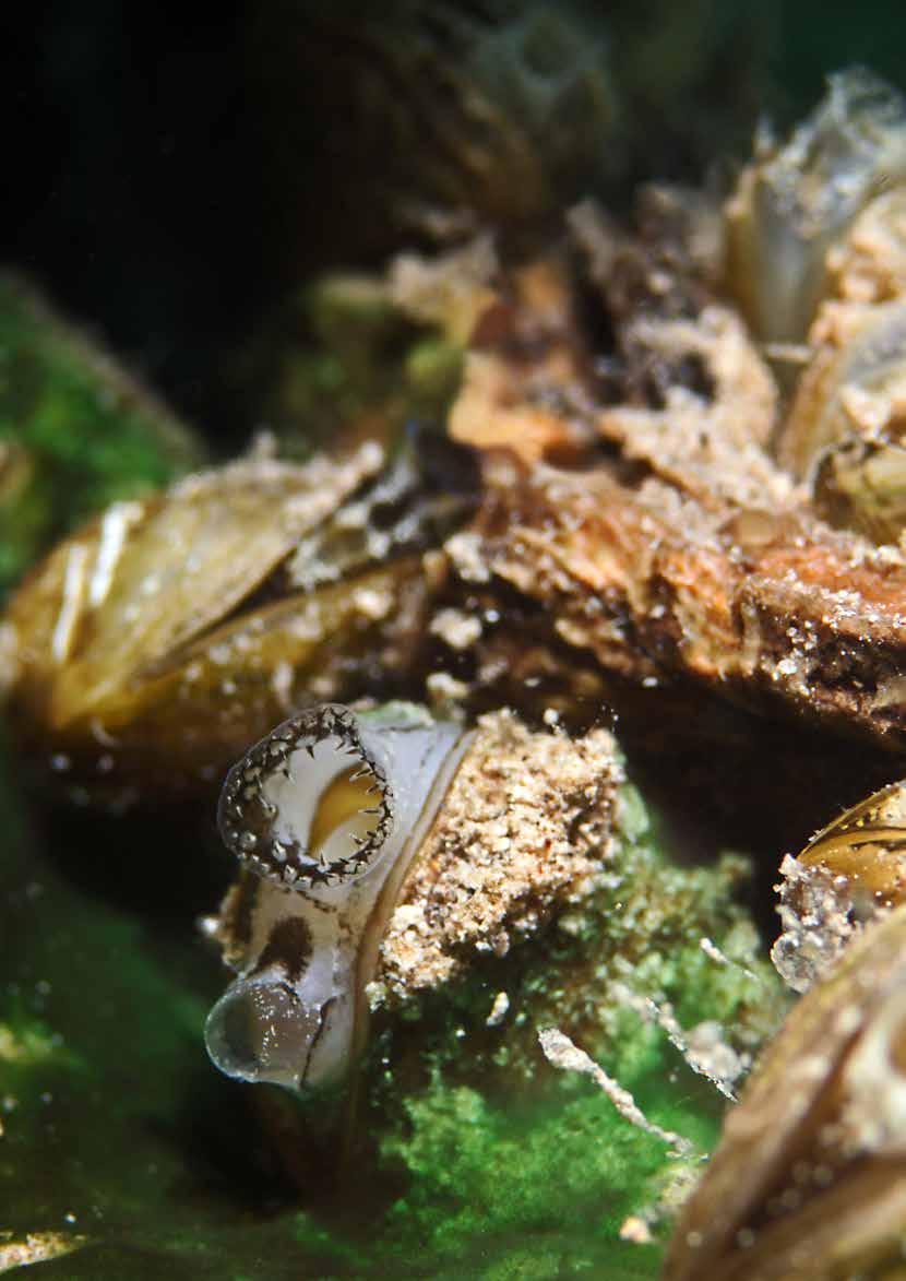
5 The ballast water issue Ballast water is fresh, brackish or marine water that is pumped into a vessel s holding tanks. It provides stability, reduces stress on the hull and improves both propulsion and manoeuvrability, compensating for weight loss due to cargo operations or fuel and water consumption. In short, ballast water is essential to commercial shipping, accounting for an estimated three to five billion tonnes of ballast water transported each year When vessels pump in ballast water in one location, they also take in a variety of indigenous organisms. These are later released into other locations, outside of their natural habitats. On any given day, the ballast water in transit aboard the world s fleet contains up to 10,000 different marine species. In most cases, the transported species do not survive when the ballast water is discharged. However, some organisms thrive in their new environment. With no natural predators, they outcompete, displace or kill native species, causing irreversible loss of diversity in the world s marine ecosystems. While only some non-native species negatively impact their new environments, those that do can pose serious risks to local ecosystems, human health and regional economies. The damage they cause is typically severe and irreversible, and attempts to limit further destruction are often costly. For these reasons, various bodies within the international maritime community have worked to establish standards for managing controlling ballast water to minimize and ultimately eliminate the transfer of harmful aquatic organisms and pathogens. The first aim of this book is to help vessel owners and operators understand these new regulations and what they mean for existing shipping operations. A vast range of technological solutions have emerged to help ships comply with the new ballast water management requirements. This book s second goal is to provide an introduction to the available compliance alternatives. It presents a comprehensive overview of both the benefits and the limitations of the most common types of ballast water treatment systems on the market. The later portion of this book is intended to serve as a guide for selecting the right ballast water treatment system and supplier to match the unique demands of a specific vessel. In addition to providing a comparison of technologies, the book highlights the capabilities a supplier must have in order to deliver the most reliable and cost-effective solution for the long term. Alfa Laval s own capabilities as a supplier of ballast water treatment solutions and an overview of the Alfa Laval PureBallast 3.1 system are presented in the final chapter. This book offers all the information ship owners and operators must know to understand what is now required of them, and to make the smart decision in every step of the process of selecting a compliance solution. The text is filled with useful links and other important resources that make this a guide worth referring to again and again even long after a ballast water treatment system has already been installed. Range of the European green crab One of the top 100 worst invasive species in the world, the European green crab has been introduced in waters far from its natural range. The species has drastically reduced the populations of native species, threatening coastal ecosystems and the local human populations they support. A list of 10 common invasive marine species and their environmental and economic impacts can be found in Appendix A. Source: National Introduced Marine Pest Information System (NIMPIS), Australia Introduced Native Ballast water treatment systems 5
6 Chapter
7 The rules for compliance Invasive marine species carried in the ballast water of ships pose significant risks to the environment, the economy and human health. To reduce the spread of invasive organisms and pathogens, a number of international, national and regional authorities have enacted regulations for the management of ballast water on vessels travelling between different ports. A comprehensive understanding of these new requirements is vital for the owners and operators of any ships that carry ballast water. A long-expected reality After years of negotiations within the global maritime community, regulations for ballast water management are entering into force at the international, national, regional and local levels. Two of the most significant regulations are those of the International Maritime Organization (IMO) and the United States Coast Guard (USCG). Approximately 25 other nations and regional authorities have taken a unilateral approach and set into force their own requirements for ballast water management (BWM). International Maritime Organization regulations IMO International Convention for the Control and Management of Ships Ballast Water and Sediments (also known as the IMO Ballast Water Management Convention or the BWM Convention) IMO, the maritime regulatory agency of the United Nations, has led two decades of efforts to stop the transfer of potentially harmful organisms and pathogens to non-native environments via ballast water discharge. The IMO International Convention for the Control and Management of Ships Ballast Water and Sediments, commonly referred to as the BWM Convention, requires ballast water to be treated to specific standards prior to discharge, and permits national, regional and local authorities to apply their own regulatory framework in their respective territorial waters. Entering into force on 8 September 2017, the convention applies to all vessels that carry ballast water and are engaged in international voyages. Background The first documented introduction of an invasive marine species into a non-native environment occurred in However, it was not until the 1970s and 1980s that the issue gained broad attention within the global maritime community, after increased global trade created greater opportunities for the spread of invasive species. In 1991, IMO s Marine Environment Protection Committee (MEPC) adopted guidelines to prevent the introduction of unwanted organisms and pathogens through the discharge of ballast water into new geographic areas. In 2004, after significant negotiation among IMO member states, the agency adopted the BWM Convention. The treaty required ratification by a minimum of 30 member states representing at least 35% of the world s merchant shipping gross tonnage. Full ratification was achieved on 8 September 2016, with entry into force to follow 12 months later. BWM Convention regulations There are several key regulations of the BWM Convention that impact owners and operators of vessels that carry ballast water and are engaged in international shipping. The most significant are IMO Regulations B-3, B-4, D-1 and D-2, which collectively define the rules for the exchange and management of ballast water. Ballast water treatment systems 7
8 Regulations B-4 and D-1: Ballast Water Exchange and Ballast Water Exchange Standard Effective as a voluntary measure in certain regions since 2009, Regulations B-4 and D-1 establish a standard for ballast water exchange to minimize the spread of invasive species. Regulation B-4 stipulates that vessels performing ballast water exchange should do so in open ocean, at least 200 nautical miles from the nearest land and in waters at least 200 metres in depth. Regulation D-1 requires an efficiency of 95% volumetric exchange. As of 8 September 2017, all vessels carrying ballast water must be in compliance with these rules unless using a ballast water treatment system with IMO type approval (see next section on Regulation D-2). The D-1 standard provides for three methods of ballast water exchange: the sequential method, the pumpingthrough method and the dilution method, as well as any combination of these. Table 1.1 offers detailed information on each method. Contact with high-salinity, open-ocean water is intended to kill the low-salinity non-native species typically originating from coastal regions. While open-ocean waters also contain organisms and pathogens, these are generally sparsely distributed and deemed to pose a lower risk of invasion. However, because ballast water exchange has limited effectiveness and poses safety risks for the vessel, IMO regards this as an intermediate solution that will be phased out over time. Most vessels will eventually be required to install an onboard ballast water treatment system that meets the standard described in BWM Convention Regulation D-2. Table 1.1: Acceptable methods of open-ocean ballast water exchange Ballast water exchange method Sequential pump-out refill method Pumping-through method (flow-through method) Dilution method Description This method requires first emptying a ballast tank completely and then refilling it with replacement ballast water. Using bottom-up techniques to fill the tank, this method requires pumping replacement ballast water into the tank, allowing water to flow out through overflow or other arrangements. At least three times the volume of each tank must be pumped through in order meet the D-1 standard. This method requires replacement ballast water to be filled from the top of the tank while the original ballast water is simultaneously discharged from the tank s bottom at the same flow rate, maintaining a constant level in the tank throughout the exchange. At least three times the volume of each tank must be pumped through in order meet the D-1 standard. Regulations B-3 and D-2: Ballast Water Management and Ballast Water Performance Standard Regulation B-3 of the BWM Convention requires vessels to perform ballast water management using a type-approved treatment system that meets the performance standard defined in Regulation D-2. The latter regulation stipulates limits for the number of viable organisms and the concentrations of indicator microbes permitted in ballast water discharge. These limits are outlined in Table 1.2. There are a variety of ballast water treatment technologies available that comply with the D-2 performance standard. These include systems that provide physical solid-liquid separation as well as disinfection by means of chemical or physical treatments. An overview of these technologies and their different strengths and limitations can be found in Chapter 2. All vessels regardless of construction year and ballast water capacity must be in compliance with the D-2 standard by the date of their first IOPP renewal survey following the BWM Convention s entry into force on 8 September Ships built prior to the BWM Convention s entry into force must be retrofitted with a type-approved ballast water treatment system, while new ships are required to have one installed at the time of delivery. Ships operating without a treatment system can remain in compliance with the BWM Convention until their next scheduled dry docking by meeting the ballast water exchange standard described in Regulations B-4 and D-1. 8 Ballast water treatment systems

9 Table 1.2: BWM Convention performance standards Biological constituent minimum dimension Greater than or equal to 50 μm* Less than 50 μm and greater than or equal to 10 μm Indicator microbes <10 μm Toxicogenic Vibrio cholerae (O1 and O139) Escherichia coli Intestinal Enterococci Discharge limitation Less than 10 viable organisms per cubic metre of ballast water Less than 10 viable organisms per millilitre of ballast water Specified concentrations Less than 1 colony-forming unit (CFU) per 100 millilitres or less than 1 CFU per 1 gram (wet weight) zooplankton samples Less than 250 CFU per 100 millilitres Less than 100 CFU per 100 millilitres *Reference: 50 μm (microns) is about half the thickness of an average human hair Regulation D-3: Approval Requirement for Ballast Water Management Systems In addition to meeting performance standards defined in Regulation D-2, Regulation D-3 requires that ballast water treatment systems receive type approval from an IMO surveyor in order to be considered in compliance. This applies to all systems, regardless of treatment technology. Approval is conducted in accordance with IMO guidelines (see later section on BWM Convention technical guidelines). Survey and certification requirements for ballast water management According to the BWM Convention, all vessels with a gross tonnage of 400 or greater are subject to regular surveys and inspections. To ensure that ballast water management is carried out according to regulated procedures and standards, all ships must have on board: An approved, ship-specific Ballast Water and Sediments Management Plan An Ballast Water Record Book An valid international Ballast Water Management Certificate. Examples of the general contents of a Ballast Water and Sediments Management Plan and a Ballast Water Record Book can be found in Appendix B. A thorough Ballast Water and Sediments Management Plan gives a shipmaster access to required reporting data for different Port State Authorities, as well as the information necessary to conduct D-1 compliant ballast water exchange anywhere in the world. It thus helps vessels avoid delays in port. Ships are required to enter any accidental non-compliant discharge into the Ballast Water Record Book. This information should be signed by the officer in charge and immediately reported to the concerned Port State Authority. Ballast water treatment systems 9
10 BWM Convention technical guidelines IMO has developed and adopted technical guidelines to support the BWM Convention, clarify its requirements and ensure uniform implementation of the regulations discussed previously. An introduction to these guidelines can be found in Appendix C, and more detailed information is available at While each guideline provides a framework for the practical implementation of the BWM Convention, the Guidelines for Ballast Water Sampling (G2) and Guidelines for Approval of Ballast Water Management Systems (G8) are particularly important to consider. Proper ballast water sampling procedures and the proper selection and operation of a treatment system are vital in preventing the transport of invasive species and ensuring compliance with the BWM Convention. Accurate knowledge of the G2 and G8 guidelines is therefore essential for ship owners and operators to minimize the risk of non-compliance. Compliance with Guidelines for Ballast Water Sampling (G2) In May 2013 the MEPC approved BWM.2/Circ. 42, Guidance on ballast water sampling and analysis for trial use in accordance with the BWM Convention and Guidelines (G2), to provide general recommendations on sampling and analysis methodologies for compliance testing of Regulation D-1 and D-2 standards. It is important for owners, operators and builders of vessels that carry ballast water to understand sampling requirements and procedures in order to ensure the proper configuration of ballast water treatment systems and proper crew training. The MEPC therefore recommends that stakeholders review BWM.2/ Circ.42 in addition to the BWM Convention, Port State Control Guidelines (see next section), G2 guidelines and other documents that provide guidance for assessing compliance with discharge standards. Port State Control guidelines The guidelines for Port State Control (PSC) provide inspection guidance for verifying BWM Convention compliance. The guidelines recommend four stages of PSC inspection: 1. Initial inspection The initial inspection focuses on the vessel s documentation, including the Ballast Water and Sediments Management Plan, Ballast Water Record Book and Ballast Water Management Certificate mandated by the BWM Convention. It also involves a visual check of the overall condition of the ship s ballast water treatment system and confirmation that the officer responsible for the system is adequately trained in its operation. 2. More detailed inspection PSC guidelines identify when clear grounds exist to conduct a more detailed inspection. This includes checking the operation of the ballast water treatment system and its self-monitoring indicators to ensure that the system has been operated according to the management plan. 3. Sampling Sampling involves a measurement and analysis of parameters that are not direct factors for D-2 compliance, but which indicate if a ballast water treatment system is performing according to the D-2 standard. These parameters can include levels of dissolved oxygen and residual chlorine. If sampling results exceed the specific criteria of the analysis method being used, the PSC official can proceed to Stage Detailed analysis If required, sampling of ballast water discharge can be used to verify compliance with the D-2 standard. This analysis will take several days. The PSC official should not delay the ship s movement, operation or departure while awaiting results. The PSC guidelines also address control of ships due to violations in sampling results, including detainment and stopping discharges. Ship owners and operators should also be aware that the United States has placed a reservation on these guidelines, stating that their implementation cannot remove the right, provided for in the BWM Convention, of port states to carry out more rigorous testing of ballast water discharge. United States Coast Guard regulations USCG Standards for Living Organisms in Ships Ballast Water Discharged in U.S. Waters (also known as the USCG Ballast Water Discharge Final Rule or USCG Final Rule) In March 2012, the USCG published the Standards for Living Organisms in Ship s Ballast Water Discharged in U.S. Waters, commonly referred to as the USCG Final Rule. The legislation went into effect in June The USCG Final Rule applies to all ships equipped with ballast tanks that operate in United States waters or are bound for United States ports. However, a number of vessel types are explicitly exempt from Final Rule requirements, including crude oil tankers engaged in coastwise service and vessels operating exclusively within one Captain of the Port Zone. Two federal agencies are responsible for regulating ballast water discharge in the United States: the USCG, acting under the authority of the National Invasive Species Act (NISA) of 1996, and the U.S. Environmental Protection Agency (U.S. EPA). There are also individual state regulations that may apply to vessels carrying ballast water. 10 Ballast water treatment systems
11 In addition to following the ballast water discharge standards of the USCG Final Rule, vessels sailing in United States waters are required to adhere to the specific limitations of the U.S. EPA Vessel General Permit (VGP). More information on VGP requirements can be found later in this chapter and at Overview of the USCG Ballast Water Management Program To comply with the USCG Final Rule, all vessels must employ one of the following ballast water management options when operating in the United States or travelling to a United States port: Install and operate a ballast water treatment system that has been type approved by the USCG according to Title 46 of the U.S. Code of Federal Regulations Part 162. Exclusively use ballast water that has come from a public water system in the United States. Vessels employing this method of compliance must also meet certain tank cleanliness requirements. As an interim alternative, perform complete ballast water exchange in an area 200 nautical miles from any shore prior to discharging ballast water. Employ a ballast water treatment system that has been approved by the USCG on a temporary basis, which is referred to as an Alternate Management System (AMS). Alternate Management Systems are permitted as long as they have been installed prior to the vessel s compliance date or extended compliance date for complying with the USCG Final Rule. Vessels may continue using such systems for up to five years after the required date for compliance with the Final Rule. Discharge no ballast water into United States waters. Discharge all ballast water into an onshore facility or another vessel for treatment purposes. The USCG Final Rule and BWM Convention similarities and differences The USCG Final Rule establishes a ballast water discharge standard that is essentially the same as that set by IMO in Regulation D-2 of the BWM Convention. The Final Rule requires ballast water management, reporting and recordkeeping, in addition to creating a type approval process for ballast water treatment systems. The implementation schedule for the Final Rule can be found in Appendix D. As with the BWM Convention, the USCG Final Rule requires vessels to install and operate a type-approved treatment system before deballasting into United States waters. However, the USCG s type approval process is stricter and more rigorous than the one currently laid out in the BWM Convention. In addition to more stringent shipboard tests, it includes landbased testing according to the Environmental Technology Verification (ETV) protocol of the U.S. EPA. As a result, many existing systems with IMO type approval may fail to meet USCG type approval requirements, and will therefore require retesting or redesign. Ballast water treatment systems with type approval from authorities outside the United States can be used on a temporary basis, provided they meet certain criteria in the USCG Final Rule. Additionally, system manufacturers may use test results from the IMO type approval procedure to satisfy testing and application requirements for USCG type approval. The USCG is continuously following the development of ballast water management, and may issue more stringent standards when new commercially viable technology becomes available. In a recent practicality review, however, the USCG has stated that there is no current technology to support more stringent discharge requirements. Up-to-date information about USCG requirements can be found at Vessels that do not discharge ballast water into United States waters are not required to install USCGapproved ballast water treatment systems. For more information, refer to Ballast water treatment systems 11

12 USCG reporting and recordkeeping requirements The USCG Final Rule requires ballast water reporting and recordkeeping via one of two means: the Ballast Water Management Report (BWMR) form or the Equivalent Reporting Program. When using the BWMR form (OMB Control No ), vessels must submit a form to the National Ballast Information Clearinghouse (NBIC) in conjunction with arrival in United States waters. This must be done no later than 6 hours after arrival at a United States port, or at least 24 hours before arrival for vessels travelling to the Great Lakes or the Hudson River from outside the U.S. Exclusive Economic Zone (EEZ). The USCG requires vessels to retain a signed report for at least two years. Further information and instructions on using the BWMR form can be found at To take part in the Equivalent Reporting Program, the applicant vessel must be non-seagoing and operate solely within the U.S. EEZ or Canadian equivalent. Additional requirements, restrictions and information for this programme are available at U.S. EPA Vessel General Permit monitoring and reporting requirements Enacted in 2013, the U.S. EPA Vessel General Permit (VGP) monitoring and reporting requirements state that vessels operating a ballast water treatment system must perform the following routine procedures: System functionality monitoring to verify the treatment system is operating according to the manufacturer s specifications. This includes specific metrics corresponding to the components of the treatment system as well as sensor calibration. Biological organism monitoring for three listed indicator organisms: total heterotrophic bacteria, E. coli and enterococci. Initial monitoring must be carried out twice a year, but may be reduced to once a year if sampling results are below effluent limits. If sampling results exceed effluent limits, monitoring must take place four times a year to ensure compliant biological organism levels. Currently, there are no limits applied to heterotrophic bacteria. Residual biocide and derivative monitoring for active ingredients that may be used in the treatment system. Initial monitoring is required three to five times in the first 10 discharge events (not to exceed a 180 day period). Thereafter, maintenance monitoring is required two to four times per year. The U.S. EPA 2009 National Recommended Water Quality Criteria provide a list of common biocides and residuals. Other national ballast water regulations While the USCG Final Rule remains the most significant national ballast water regulation in force, many other countries have adopted their own policies to protect their territorial waters from invasive species. Of particular note are regulations in place in Georgia, Lithuania and the Ukraine, which specifically deal with ballast water exchange in the Black Sea. Other national governments that have enacted their own legislation include: Argentina Australia Brazil Canada Chile Israel Republic of Korea New Zealand Norway Panama Peru United Kingdom National governments continue to evaluate their approach when it comes to invasive marine species in ballast water discharge. It is therefore important for vessel operators to be aware of the current laws of all countries whose ports they visit. 12 Ballast water treatment systems

13 Regional and local ballast water regulations As previously noted, the BWM Convention empowers regional and local authorities to develop their own frameworks for regulating the ballast water of ships sailing in their respective territorial waters. Various regional and local ballast water regulations are currently in effect worldwide. Some local authorities, such as the Port State Authority in Buenos Aires, Argentina, adopted regulations as early as 1990, while other regions have enacted policies more recently in anticipation of the BWM Convention entering into force. Regions with ballast water requirements in place include: Baltic Sea Mediterranean Sea Northeast Atlantic Sea Persian Gulf Requirements of individual U.S. states As of 2014, 16 of the 50 U.S. states have specific requirements for ballast water management. These states have enacted requirements either through specific state legislation or in accordance with the federal Clean Water Act (CWA), Section 401 Certifications for the 2013 VGP. California is considered to have the most stringent regulation, with requirements for ballast water management and the prevention of hull fouling on ships of 300 gross registered tonnes or more. Vessels discharging ballast water in Californian waters are currently required to conduct ballast water exchange. However, the specific exchange requirements depend on the vessel s port of origin. For more information, see the State of California s Marine Invasive Species Program, Code of Regulations Title 2, Division 3, Chapter 1. Additionally, there are a number of local ports with their own requirements. These include: Buenos Aires, Argentina Vancouver, Canada Klaipeda, Lithuania Novorossiysk, Russia Ballast water treatment systems 13
14 Chapter

15 Ballast water treatment technologies There are many ballast water treatment systems on the market that have received type approval to meet international discharge standards. For ship owners and operators, understanding the different technologies employed in these systems is important for selecting the optimal system for a specific vessel and the conditions under which it operates. Treating ballast water Various ballast water treatment systems are available for ensuring compliance with the regulations described in the previous chapter. They incorporate a range of technological solutions for minimizing the number of organisms and pathogens in ballast water discharge. These technologies can involve separation, as well as disinfection by chemical or physical means. Understanding the benefits and limitations of each technology is important for making the best decision about which one to use. No single ballast water treatment solution is suitable for all vessel types, sizes and operating conditions. In determining the right solution for a particular vessel, owners and operators need to consider a wide variety of factors regarding the vessel itself, as well as where and how it operates. Water quality and ballast water treatment One factor to consider is the quality of water that is pumped into a vessel s ballast tanks. Water quality is determined by a number of physical, chemical and microbiological characteristics. These characteristics vary considerably and can affect ballast water treatment technologies in different ways. As subsequently noted in more detail, some ballast water treatment systems have specific limitations related to water characteristics, which can impact operating parameters such as power consumption. It is therefore critical to evaluate the effectiveness of a treatment system under various water quality conditions. In assessing the operational limitations of ballast water treatment technologies, there are three primary water characteristics to keep in mind: salinity, temperature and ultraviolet transmittance. Ballast water treatment systems 15

16 Salinity Salinity refers to the total concentration of dissolved salts in a body of water. The world s oceans have an average surface salinity of about 3.5%. The level of salinity depends on the quantity of water molecules, which can be impacted by temperature, climate and season. As the number of water molecules increases, due to melting ice, precipitation or other factors, the salinity level decreases. For example, most ports are exposed to river run-off, which means their average salinity levels are generally lower than that of ocean water. By contrast, evaporation decreases the quantity of water molecules, which means the highest salinity levels are found closest to the equator. Temperature Surface water is warmed by solar radiation, which decreases with distance from the equator. The warmest water is located closest to the equator, while the coldest water is found at the poles. Ultraviolet (UV) transmittance Ultraviolet transmittance, sometimes referred to as UVT, is the measurement of how much ultraviolet (UV) light is able to pass through a sample of water. Expressed as a percentage, it refers to the transmittance of light at the 254 nanometre (nm) wavelength, which is the specific wavelength measured for water disinfection processes. See Figure 2.1. The presence of dissolved organic matter, or of dissolved inorganic matter such as metal ions, reduces the UV transmittance of a water sample in a non-linear fashion. As the distance from the light source increases, the light intensity decreases exponentially. Measuring UV transmittance identifies the amount of light that is not absorbed due to the presence of dissolved matter in water. Figure 2.1: UV transmittance and path length 100% 100% 80% 64% 1 cm 2 cm An example of UV transmittance (80%), showing the decrease in light intensity with distance from the source. Note the limited light remaining after passing through 2 cm of unclear water. 16 Ballast water treatment systems

17 Common ballast water treatment technologies Most ballast water treatment systems utilize a two-step process: physical separation (pre-treatment) followed by disinfection (main treatment). Physical separation refers to the removal of solid material, including suspended particles and larger microorganisms. Disinfection involves the use of chemical or physical treatment or a combination of treatments to destroy or neutralize microorganisms in ballast water. Table 2.1 provides an overview of the two treatment steps and different technologies available for performing them. These technologies are discussed in depth in following sections. Table 2.1: Two-step ballast water treatment process Physical separation Disinfection Treatment: Hydrocyclone Surface filtration Chemical enhancement: Coagulation/ flocculation Chemical treatment: Chlorination Electrochlorination or electrolysis Ozonation Peracetic acid Chlorine dioxide Or Physical treatment: UV irradiation UV + Titanium dioxide Deoxygenation Ultrasonic treatment Cavitation Residual control: Chemical reduction (sulphite/bisulphite) Physical enhancement: Ultrasonic treatment Cavitation Ballast water treatment systems 17
18 Pre-treatment: physical separation Pre-treatment involves physical means, sometimes supported by chemicals, to separate and remove suspended solid particles and microorganisms from ballast water as it is taken aboard. Three technologies are common to most systems that employ physical separation: hydrocyclones, coagulation/flocculation and filtration. Hydrocyclones Hydrocyclones rotate the ballast water at high velocity in a conical section in order to remove heavy particles. Their efficiency is not very high, due to the fact that many microorganisms have about the same density as the water and thus remain unseparated. Because of their limited capacity, hydrocyclones are often installed in parallel in order to treat higher flows. However, the high pressure drop across many hydrocyclones means that the available pressure from the ballast pump may be a limitation. Coagulation/flocculation Coagulation/flocculation refers to the use of chemicals to trigger the formation of larger masses, which can then easily be filtered from the ballast water. This process is time-consuming and requires a large tank, and is therefore less common than the other separation technologies. Filtration Filtration is the most common method of pre-treatment. It involves passing ballast water through fixed screens, generally with a mesh size of less than 50 μm, to remove larger particles and microorganisms. There are different types of filters available on the market for use in ballast water pre-treatment. The candle, basket and disc filter types are the most common. Candle filters This refers to a filter where multiple cylindrical or conical filter candles are installed in a single housing. Unfiltered water enters the candles from the inside and is filtered as it passes outwards through the filter weave. Almost all candle filters employ an automatic cleaning procedure called backflushing. During this procedure, the insides of the filter candles are connected one by one (or two by two) to an overboard pipe. The water flows from the outside of the candle inwards, carrying the dirt away from the candle to be flushed overboard. Backflushing is automatically initiated by an increased differential pressure between the filter inlet and outlet. Basket filters As the name suggests, these filters involve a filtering element comprised of one large basket. Water enters the basket from the inside and is filtered as it passes outwards through the filter weave. Basket filter cleaning is normally performed by an arrangement of suction nozzles connected to an overboard pipe. The nozzles pass over the filter area and the clean water enters backwards through the filter weave, passing through the nozzle and overboard. This automated cleaning process is initiated automatically by increased differential pressure over the filter area. The cleaning time varies between different manufacturers, and if there is a high dirt load it is important that the cleaning cycle is short. Otherwise there is a risk that more dirt will be caught in the filter area than what the cleaning nozzles are able to remove, which will result in a clogged filter. Disc filters Disc filters are made up of several discs with small grooves stacked on top of one another. When tightly pressed, the disks create a matrix capable of capturing solids as water passes through the filter. Like candle filters, disc filters are typically cleaned through an automatic backflushing process where the direction of the water flow is reversed. Filter mesh Regardless which main treatment technology is used, more complex organisms (such as zooplankton) require a higher dose. If too many organisms have passed the pre-treatment step, the main treatment step will not be able to compensate, which may lead to non-compliance. This places high demands on filter effectiveness, which is determined in large part by the filter mesh. The mesh size of filters used for ballast water treatment ranges from 50 μm downwards. However, different manufacturers have different ways of manufacturing the filter weave and measuring the mesh size. It is therefore impossible to judge the performance of a filter by comparing the mesh size alone. Its performance must be determined through biological tests As the filter weave becomes finer, the need for filter cleaning increases along with the number of trapped organisms. Frequent or even continuous backflushing is a result of high filter load and is normal so long as the filter is able to clean itself. If the filter cannot clean itself, it is clogged and will require manual cleaning. 18 Ballast water treatment systems

19 Main treatment: chemical disinfection In common two-step ballast water treatment systems, the initial physical separation is followed by the disinfection of the ballast water, in which any remaining organisms are neutralized. Treatment systems can employ either chemical or physical disinfection to achieve this process. Using chemicals in the ballast water treatment process can present challenges. For example, chlorine content can negatively impact carbon and stainless steel, both of which are prone to corrosion. Chlorine also affects the ballast tank coating and is known to shorten the expected lifetime of polymers. The environmental impact of other active substances, which in many cases are produced during the treatment process, has not been fully investigated. Chemical disinfection technologies use active substances that may be added or produced in situ. These active substances must be evaluated during the system certification process. The effectiveness of the chemical processes themselves varies according to the water characteristics discussed previously, as well as the type of organisms that are present. Ballast water treatment systems 19
20 Table 2.2: Chemical disinfection technologies Disinfection technology Chlorination Electrochlorination Ozonation Peracetic acid and hydrogen peroxide Chlorine dioxide Gas super-saturation (combination of chemical and physical disinfection) Method Uses approximately 1-10 ppm (mg/l) of the chlorine-based germicide sodium hypochlorite (NaOCl), added to the ballast tank to kill organisms and pathogens that have bypassed the separation step. Prior to discharge, it is important to neutralize total residual oxidants (TRO) in the ballast tank, i.e. any residual sodium hypochlorite that may be present. This is usually done through the use of sodium meta-bisulphite or sodium thiosulfate. Passes seawater through an electrolytic cell, where direct current produces chlorine and hydrogen gases. The chlorine gas is immediately dissolved in the water to produce the germicides sodium hypochlorite (NaOCl) and bromine hypochlorite (BrOCl), which neutralize microorganisms. Prior to discharge, it is important to neutralize total residual oxidants (TRO) in the ballast tank, i.e. any residual hypochlorites that may be present. This is usually done through the use of sodium meta-bisulphite or sodium thiosulfate. Generates ozone by means of either UV light or high-voltage electricity (corona discharge). Ballast water passes through a Venturi throat, which creates a vacuum that pulls the ozone gas into the water. Disinfects through the use of this chemical blend with few known harmful by-products. Disinfects quickly when added to ballast water as an aqueous solution in order to avoid problems with handling gases (accumulations of chlorine dioxide gas are known to spontaneously detonate). Depletes the oxygen supply available to marine microorganisms by injecting nitrogen gas into the ballast water in sealed ballast tanks. This causes asphyxiation or suffocation of the microorganisms. Considerations Creates undesirable by-products, including chlorinated hydrocarbons and trihalomethanes (chloroform), and may therefore require additional post-treatment, depending upon the chlorine concentration and holding time in the tank. Requires consumables as well as special ventilated storage rooms. Requires the addition of salt or high-salinity water, which must be stored on board, in order to be effective in brackish or fresh water. Low water temperature also impacts effectiveness. These factors result in significant power consumption when operating in low-salinity or colder water. Because hydrogen gas is deemed potentially hazardous, the equipment needs hydrogen traps, flame arrestors or other methods to safely handle the gas produced. Cleaning of the electrodes requires acid wash or other external electrode cleaning methods. Requires both consumables and special ventilation. Requires the use of auxiliary equipment, such as compressors, dryers and air chillers. Has greater disinfection effectiveness against bacteria and viruses than chlorination, but can also produce harmful by-products, most notably bromate and insoluble metal oxides. Requires consumables. The chemicals are relatively expensive and require high mixing concentrations as well as considerable storage space. Requires consumables. Requires safe storage and handling on board. Rarely used despite its fast-acting disinfection capabilities, due to excessive amounts of toxic chlorite that are produced in some circumstances. Requires consumables. A treatment time of several days in the ballast tanks is needed for the method to be effective. A nitrogen generator must also be installed on board, which is a complicated installation with a large footprint. 20 Ballast water treatment systems

21 General considerations for chemical disinfection technologies When considering a ballast water treatment system that employs chemical disinfection, there are additional factors that ship owners and operators should be aware of. Holding time Type approval of ballast water treatment systems requires the specification of the ballast water holding time, i.e. the necessary interval between ballasting and deballasting operations to ensure effective treatment. Holding times can vary from seconds to days. The required minimum is normally 24 hours, but some chemical technologies require holding times of up to five days. A number of treatment systems may therefore be unsuitable for vessels that ballast and deballast frequently. During long voyages, there is also a risk of regrowth if all active substances are consumed, which may result in non-compliance at discharge. Total residual oxidants Total residual oxidants (TRO) are the active substances left by ballast water treatment systems that make use of oxidants, such as electrochlorination systems. TRO levels decrease with holding time as oxidants are consumed. TRO is often expressed as Cl 2 and is measured in mg/l or ppm. To limit impact on the environment and meet international regulations, TRO levels at discharge must be not greater than 0.1 mg/l. Some ballast water treatment systems achieve this level after treatment, but others do not. If TRO levels exceed the 0.1 mg/l limit prior to deballasting, the ballast water must undergo additional post-treatment to neutralize the remaining TRO. Sodium meta-bisulphite or sodium thiosulphate is often used for this purpose. Electrochlorination technologies Electrochlorination, or electrolytic chlorination, is the most common chemical disinfection technology used in ballast water treatment systems. Electrochlorination systems produce a disinfecting hypochlorite solution from a common salt solution using electricity, which produces hydrogen gas as a by-product. Electrochlorination systems involve a large footprint and complex installation, with numerous components, pipes and safety arrangements. They can be set up as main-stream systems, where the total ballast water flow is led through an electrochlorination unit, but also as by-stream systems, where just 1% of the ballast water is treated to a high concentration before being injected into the main flow. Both setups often feature pre-treatment by means of filter. Electrochlorination systems treat water once during ballasting, which can be advantageous but also has disadvantages. The lack of treatment during deballasting ignores the potential for regrowth in the tank due to long holding times, which in turn increases the risk of non-compliance. Neutralization of TRO levels may also be necessary prior to the discharge of ballast water, and additional sampling and monitoring may be required to ensure compliance. The following is a brief list of specific considerations for evaluating electrochlorination treatment systems. This list is by no means comprehensive, and it is important to refer to the guidelines and regulations that various authorities have established in order to ensure compliance. Ballast water treatment systems 21
22 Water salinity When ballast water salinity is low, the efficiency of an electrochlorination system decreases while its power consumption increases. Low salinity makes it difficult to generate the hypochlorite disinfectant. The solution is to add salt, either by dosing it directly into the water or by using a separate high-salinity water source, typically the aft peak tank. The crew must make sure that high-salinity water is available in sufficient quantity at all times. If the system is not fully automatic, this increases the complexity of both installation and operation. Additional piping and pumps may be necessary. Using added high-salinity water is only possible with by-stream systems, where 1% of the water is used to produce enough hypochlorite to treat the whole water volume. Water temperature Lower water temperatures also increase the consumption of energy needed to produce hypochlorite and disinfect the water. Energy use in an electrochlorination system follows an exponential curve. Optimal water temperature for the operation of the electrochlorination process is above 15 C, with normal low-end temperatures in the range between 10 C and 17 C. Water below 10 C significantly reduces the formation of chlorine. Colder seawater therefore needs preheating in order for the system to perform effectively and ensure compliance. Ventilation Electrochlorination processes generate hydrogen and chlorine gases, which are explosive and toxic. The mixture of hydrogen and chlorine is far more flammable than mixtures of hydrogen and air, and must therefore be avoided at all costs. Management of dangerous gases is important to consider when installing electrochlorination systems on ships, and classification society requirements for system ventilation should be observed. Chemical storage In addition to ventilation for the electrochlorination system, it is important to consider safety measures for storing the chemicals. Separate, explosion-proof storage compartments with ventilation may be necessary. Handling the chemicals may also require additional safety equipment and special training for the crew. Disinfection by-products The formation of disinfection by-products (DBPs) can occur when using electrochlorination or chlorination. DBPs are the result of reactions that occur during the treatment process when organic content is present in the water. Where organic content is higher, as it tends to be in brackish water, higher DBP levels can be expected. Currently there are no regulated limits for DBPs, and only a fraction of all DBPs are measured during ecotoxicological evaluation. However, a number of studies have raised questions regarding the long-term environmental impact of DBPs discharged in ballast water following electrochlorination treatment.* Although not all long-term effects of DBPs in ballast water are yet known, some DBPs can be very toxic to marine organisms and can result in bioaccumulation of toxins over time. It is difficult to assess the potential damage of long-term exposure to the chemicals used in ballast water treatment, but there is some evidence of genetic damage, adverse effects on the development of marine organism reproductive systems and loss of marine biodiversity. *For one example, see: Emerging risks from ballast water treatment: The run-up to the International Ballast Water Management Convention, Chemosphere, 112 (2014), Ballast water treatment systems
23 Main treatment: physical disinfection Physical disinfection of ballast water is an alternative to chemical disinfection. Most systems using physical disinfection treat ballast water during both ballasting and deballasting. Like chemical disinfection, physical disinfection processes offer both benefits and limitations. The effectiveness of physical disinfection processes is similarly dependent upon various ballast water characteristics and the type of organisms that are present. Table 2.3: Physical disinfection technologies Disinfection technology Ultraviolet (UV) irradiation Advanced oxidation technology (AOT) using UV and titanium dioxide Enhanced UV treatment Deoxygenation Cavitation Method Uses low-pressure amalgam or mercury lamps or medium-pressure mercury lamps surrounded by natural quartz sleeves to produce UV light that disrupts the DNA of marine organisms, preventing them from reproducing. Combines direct UV treatment with a titanium dioxide (TiO 2 ) catalyst and synthetic quartz glass sleeves to generate radicals that react with microorganisms and other organic contaminants. This destroys cell membranes and prevents organism reproduction or regrowth. Uses medium-pressure mercury lamps to produce UV light that passes directly through synthetic quartz glass sleeves, thus generating radicals that react with microorganisms and other organic contaminants. This destroys cell membranes and prevents organism reproduction or regrowth. Depletes the oxygen supply in ballast water by injecting nitrogen, carbon dioxide or other inert gas into the space above deaerated water in sealed ballast tanks. This causes the asphyxiation or suffocation of marine organisms. Uses high-power ultrasound waves to generate cavitation bubbles in the ballast water. The generation and collapse of the bubbles result in intense shear forces and high stress that kill organisms by effectively breaking their cell walls. Considerations Requires large amounts of energy. Low-pressure lamps use less power, but have a larger footprint than mediumpressure lamps due to a longer lamp length and the need for up to 10 times as many lamps. Has a higher UV optical efficiency than standard UV lamps, due to the use of synthetic quartz sleeves. The drawbacks are cost and the partial shadowing of the light by the catalyst. Has a higher UV optical efficiency than standard UV lamps, due to use of synthetic quartz sleeves. This increases the biological performance without affecting the power consumption. Requires holding time of 1-4 days to effectively kill the organisms and is therefore not suitable for ships with short transit times. Significantly reduces tank corrosion due to the lack of oxygen. Equipment is needed to produce the inert gas. Is not known or anticipated to pose any environmental concerns. System capacity is highly energy dependent, and the process may have an adverse effect on ship coatings, tank coatings and/or ship structure. Ballast water treatment systems 23
24 Ultraviolet (UV) technologies UV light has been used to disinfect drinking water for 100 years and is frequently used in ballast water treatment as well. UV systems represent the most common form of physical disinfection technology. They operate by directing ballast water into a disinfection chamber, or reactor, where lamps produce UV light at wavelengths of around 185 or 254 nm, depending on the lamp type and the quality of the quartz glass sleeves. In most systems, the disinfection phase follows mechanical filtration that removes larger particles and organisms. The UV light is continuously monitored during system operation to maintain the proper intensity and ensure that the required dose for maximum efficiency is achieved. The quartz lamp sleeves sometimes feature automatic wiping systems that minimize biofouling and the accumulation of deposits that weaken UV transmittance and thereby reduce efficiency. In other systems, immersed washing is used for this purpose. Some systems also offer automatic reduction in power consumption when operating in waters with high UV transmittance. Following UV disinfection, the water flows to the ballast tanks. During deballasting, ballast water is pumped back through the reactor, where it receives a final treatment before discharge. Additional mechanical filtration is not generally used. Because treatment takes place during both ballasting and deballasting, there is minimal risk that regrowth in the tanks will lead to non-compliance. UV systems require no minimum holding times and offer short treatment time and minimal space requirements. Unlike chemical disinfection methods, UV irradiation does not generate harmful by-products or residual disinfectants. UV systems have little or no impact on the environment and do not contribute to the corrosion of ballast tanks over time. UV lamp configuration The functionality and performance of UV treatment systems vary depending on the types of technical solutions they employ, including the configuration of the UV lamps. UV lamps used in ballast water treatment can be of the low-pressure or medium-pressure type. Regardless of the type used, the lamps are typically oriented perpendicular to the water flow inside of the reactor, and most systems use many lamps in order to achieve the required level of disinfection. There are, however, exceptions in which the water flows along one large medium-pressure UV lamp. Low-pressure vs. medium-pressure UV lamps Low-pressure UV lamps are the most effective at converting electricity into UV light, with efficiencies of around 30 to 40%. They also burn at lower temperatures (around 100 C), which results in a longer operating life of between 5000 and 10,000 hours. Figure 2.2: Wavelengths of low-pressure amalgam lamps Spectral irradiance, au nm Source: Heraeus Noblelight 254 nm Wavelength, nm Since they burn at higher temperatures (around 900 C), medium-pressure UV lamps have a somewhat shorter lifetime, typically lasting between 1000 and 8000 hours. They are also more dependent on safety systems that monitor the presence and temperature of the water inside of the reactor, initiating automatic system shutdown if there is a risk of overheating. However, medium-pressure lamps produce a much higher output per unit of lamp length. Their efficiency in converting electricity into UV light is between 10 and 15%, yet they are more efficient for many photochemical applications due to their broader emission spectrum. Figure 2.3: Typical spectrum of medium-pressure mercury lamps Spectral irradiance, W/m 2 nm 200 Source: Heraeus Noblelight Wavelength, nm The UV lamps are isolated from the flow of water by protective quartz sleeves. Both the type of lamp and the type of quartz used have implications for the system, as outlined in the following sections. 24 Ballast water treatment systems
25 Low-pressure lamps are typically used in drinking water applications, where the water is clear. In these applications, they are the last step in a long cleaning process that targets only bacteria. Conversely, the higher intensity and broader spectrum emitted by medium-pressure lamps results in better biological performance when the water has low UV transmittance. The light of medium-pressure lamps penetrates water further, which is essential for ballast water treatment. The higher intensity of medium-pressure lamps also delivers a substantial shock to organisms, which impairs their ability to self-repair. As a result, the lamps are more effective in preventing regrowth after treatment. Finally, systems that use low-pressure lamps must employ more and longer lamps to produce the level of UV light required to disinfect water according to IMO and USCG standards. A typical 1000 m 3 /h system uses around 100 low-pressure lamps with a length of around 1.3 metres. Such configurations increase the risk of leakage or vibration problems, which can result in higher maintenance costs. Natural vs. synthetic quartz Natural or synthetic quartz can be used in both UV lamps and the sleeves that protect them. While synthetic quartz is more expensive than natural quartz, it yields two significant benefits: 1. UV light is emitted also at a shorter wavelength. This produces radicals close to the sleeve, which enhances the biological performance through photoionization. 2. UV output increases by around 15%. In short, using synthetic quartz increases biological performance and allows a reduced number of lamps. A UV reactor with eight lamps in synthetic quartz sleeves offers comparable performance to a reactor with nine lamps protected by natural quartz sleeves. Figure 2.4: Comparison between natural and synthetic quartz UV transmittance, % nm Disinfection nm Oxidation Wavelenght, (nm) Synthetic quartz glass Doped quartz glass Natural quartz glass Low-pressure spectrum Source: Heraeus Noblelight Table 2.4: Comparison of low- and medium-pressure UV lamps Low-pressure (with high performance) Medium-pressure Electrical power 1-5 W/cm W/cm UV efficiency 30-40% 10-15% Power/lamp (typical) 0.5 kw 3 kw Lamp length 1300 mm 300 mm Lifetime* 10,000 hours 3000 hours Number of lamps, 1000 m 3 /h system *Note: Total operating hours is only one parameter for determining lamp lifetime. It is also important to consider the number of times a lamp is powered on or off, which has a particularly negative impact on the lifetime of low-pressure lamps. Ballast water treatment systems 25

26 Operation and maintenance considerations for UV systems There are a number of factors to consider regarding the operation and maintenance of UV systems. Some of these relate to the systems themselves, while others deal with how the systems interact with the treatment environment in which they operate. UV lamp start-up UV lamps generally require a warm-up period in order to reach operating temperatures that generate the correct treatment spectrums. Start-up cooling water is required, since temperatures can reach up to 900 C at the surface of a medium-pressure lamp. This water can be supplied by a separate sea-to-sea cooling circuit, or by adjusting the vessel s main valves to run ballast water through the system sea-to-sea. A separate cooling circuit is preferable, as working with the valves can lead to mistakes and potential contamination. UV lamp replacement The optical output of a UV lamp diminishes gradually over time, necessitating periodic lamp replacement. The average service life expectancy for UV lamps depends on the frequency of their use as well as the type of lamp selected. The optical output, in relation to other factors like water composition, is monitored by a UV intensity sensor. Quartz sleeve cleaning Fouling on the protective quartz lamp sleeves reduces UV transmittance, which in turn decreases disinfection effectiveness. The majority of UV systems use frequent cleaning to remove the build-up of contaminants from the surface of the quartz lens. There are two main methods for cleaning quartz sleeves and a system s light-measuring sensors: 1. Mechanical cleaning, which uses wipers that physically remove fouling as they move up and down the sleeves. 2. Immersed washing that thoroughly removes any contamination or residue on the lamp sleeves and sensor surfaces. Mechanical cleaning places moving components, which will eventually require replacement parts, inside the reactor housing. In addition, the effectiveness of mechanical cleaning depends on the quality of the ballast water. For example, wipers are ineffective against metal ions in water, which can bond chemically to the quartz sleeves and inhibit the disinfection performance of the UV system. Only a mild acid will remove this sort of scaling. If using a system with built-in power-saving capabilities, fouling left behind by the wipers may also reduce the potential energy savings. Immersed washing cycles use safe, non-abrasive agents to clean the quartz sleeves, followed by a thorough rinsing of the system to prevent corrosion. These so-called Cleaning-In-Place (CIP) systems effectively remove build-up and maintain the system s disinfection performance over time. In addition, they eliminate the risk of wiper failure or wiper scratches on the quartz sleeves that can negatively impact UV transmittance. UV transmittance UV transmittance pertains not only to the quartz lamp sleeves, as noted previously, but also to the water treated. Many UV ballast water treatment systems are tested in clear water with high UV transmittance. 26 Ballast water treatment systems
27 However, while seawater generally has high UV transmittance, the UV transmittance of water along coasts and in harbours tends to be lower. This can impact the performance of a system in practice. Some systems tested with clearer water can experience difficulties when treating water with low UV transmittance. It is thus important to know the UV transmittance value of the water that will be treated. UV transmittance levels in harbours usually range from 90% down to 60%, but can sometimes fall to 50% or below. Selecting a UV system that can handle a UV transmittance value of 50% or lower ensures compliant disinfection of ballast water in most harbours and ports. It is vital to verify a system s UV transmittance capabilities by referring to its Type Approval Certificate and consulting the manufacturer for specific details and updated information. Water temperature Broadly speaking, UV systems are able to treat ballast water in cold water conditions. However, due to their generation of heat, medium-pressure UV lamps offer the widest operational temperature spectrum. In areas with near-freezing water temperatures, medium-pressure lamps will perform where low-pressure lamps may cease to function. When selecting a UV system, it is therefore important to refer to manufacturer information about system performance in various temperature conditions. Although UV systems that use medium-pressure lamps are not dependent on water temperature, the water must be fluid in order to pass through the filtering stage. Water salinity UV treatment technology is not directly affected by salinity. However, there are often limitations for UV systems in fresh water due to lower average UV transmittance levels. Corrosion UV treatment systems do not contribute to corrosion in the ballast tanks and piping. Safety UV systems must be fitted with sensors to monitor temperature and water level in the treatment reactor. The control system shall automatically initiate a shutdown in the event of overheating. Power management Power management maintains treatment performance when moving between waters with varying UV transmittance. The power employed is decreased when sailing in clear water conditions, or increased under difficult circumstances where UV transmittance is low. The power adjustment should be fully automatic and immediately responsive to changes in the water conditions to ensure compliant disinfection at all times. Sampling and analysis Determining whether any ballast water treatment system meets discharge standards places considerable focus on sampling and analysis techniques. Whereas the old IMO G8 guidelines lacked specific guidance, which resulted in varying interpretations among land-based test facilities, the revised G8 guidelines will harmonize the way ballast water is tested. The revised G8 guidelines define viable organisms as having the ability to successfully generate new individuals in order to reproduce the species. Viability may be assessed on the basis of one or more essential characteristics of life, such as structural integrity, metabolism, reproduction, motility or response to stimuli. The Environmental Technology Verification (ETV) protocol of the U.S. EPA is more specific, requiring the use of CMFDA/FDA stains to categorize organisms in the μm size class as live or dead. The stains indicate the ability of an organism s esterase system to function. At present, CMFDA/FDA staining is the only method approved for determining compliance with the USCG Final Rule. An alternative to CMFDA/FDA staining, the most probable number (MPN) dilution-culture method, has been employed and accepted for IMO certification. The MPN method is more appropriate for determining the effectiveness of UV treatment on organisms in the μm size class, because UV treatment can neutralize organisms in two ways. Organisms may be destroyed outright, but they may also be rendered unable to reproduce which is equally effective in terms of stopping species invasions. While the MPN method has not yet been approved by the USCG, there is an ongoing discussion that may lead to its acceptance in the future. Ballast water treatment systems 27

28 Chapter
29 Selecting the right ballast water treatment system A ship owner s most valuable asset is the ship itself. Optimizing the value of a vessel means making sound purchasing decisions throughout its life cycle, particularly when it comes to the installation of new mandatory components such as a ballast water treatment system. The selection of a treatment system should be based not only on the factors that ensure compliance, but also those that impact the ship s operating costs, resale value and total lifetime costs. The value of a ballast water treatment system The selection of a ballast water treatment system is about more than complying with international regulations and requirements. It also influences the total value of a ship. The capital investment in a system is just one factor of its total cost of ownership and should be considered alongside the system s long-term operating expenses. A system with low upfront capital costs may have high operating and maintenance costs over time. Conversely, a system requiring a higher initial investment may require fewer additional expenses in the long run. Evaluating cost As noted in the previous chapter, many ballast water treatment systems require ancillary equipment in order to operate both safely and effectively. This may include components for ventilation, chemical storage, water heating or increasing salinity. It is important to make sure that these components are factored into the overall cost of installing a treatment system. In some cases, the initial investment in a treatment system may be larger than first anticipated once all of the necessary equipment has been taken into account. Beyond the capital expenditure (CAPEX), there are two main parameters to consider in evaluating the true price of a ballast water treatment system: the annual operational expenditure (OPEX) and the total lifecycle costs (LCC). Operational expenditure In the context of ballast water treatment, OPEX refers to the annual expenditure for all consumables, including spare parts and energy usage. For systems using chemical disinfection technology, OPEX includes not just the required chemicals themselves, but also costs related to the handling of chemicals and the management of by-products and residual oxidants. The total OPEX of a treatment system can be much higher than expected after considering the operational needs of pumps, tanks, heating sources and other vital components. These factors can increase the overall power consumption and performance costs of a system beyond the supplier s claims. Because the efficiency of a ballast water treatment system decreases over time, it is also important to assess how its OPEX will change in the long term. The operational costs for a system in its first year of service will generally be lower than five or ten years down the road. As an example, the wipers used in a UV system with mechanical cleaning can scratch the quartz lamp sleeves. This will lead to lower UV transmittance and a gradual increase in energy consumption. Lifecycle costs Lifecycle costs refer to the additional capital invested in a ballast water treatment system throughout its service life. They can include maintenance and repair expenses, as well as replacements or upgrades of the system s components and supporting equipment. The cost of replacement components over the life of a system can ultimately be much higher than the original investment. System design and the materials used have a large impact on the lifetime of individual components and the need for maintenance. Higher quality components tend to increase upfront costs, but may mean fewer problems with the system over time, which will lower both OPEX and LCC. The number of components used in a treatment system also affects its LCC. For example, a UV system using low-pressure lamps will often have more than six times the number of lamps found in systems with medium-pressure lamps. Even though low-pressure lamps have a longer service life, the cost for mediumpressure lamps throughout the lifetime of the system may be lower, simply because there are far fewer to replace. Ballast water treatment systems 29
30 The operational limitations of a treatment system can further raise LCC by increasing the risk of non-compliance and therefore the risk of heavy fines. Even systems with few operational limitations pose a threat to compliance if they are difficult and complex to use, as this creates possibilities for cross-contamination, system malfunction and human error. These issues are addressed in greater detail in the next section. A thorough evaluation of LCC should consider not only the main parts of a system, but also how the system s operation affects the vessel as a whole. Treatment technologies that increase the risk of corrosion in pipes and ballast tanks, for example, can negatively impact a ship s overall value. Ensuring trade route access and profitability The prevention of income loss is a further factor to consider when selecting a ballast water treatment system. Whether a system opens or restricts access to ports around the world can help determine its potential value for a vessel. Water quality, which fluctuates throughout the year and depends on actual weather conditions, varies greatly between the world s ports. This can be seen in Table 3.1, which shows a number of prominent ports and their typical parameters. In addition, water quality impacts the success of ballast water treatment. Table 3.1: Water quality by port Port UVT(%) Temp( C) Salinity (PSU) Istanbul, Turkey San Pedro, CA, USA Halifax, NS, Canada Veracruz, Mexico Rotterdam, Netherlands Port of Singapore, Singapore Houghton, MI, USA Erie, PA, USA Zeebrugge, Belgium Gothenburg, Sweden Charleston, SC, USA Baltimore, MD, USA Hong Kong, China Houston, TX, USA Hamburg, Germany Antwerp, Belgium Bremerhaven, Germany Lisbon, Portugal Southampton, England Shanghai, China As the previous chapter demonstrates, all ballast water treatment systems have limitations in some form. Water salinity and temperature can affect the performance of chemical systems, whereas UV transmittance is the most important factor for UV treatment technologies. When operating outside their limitations, some systems will exhibit decreased performance while others will cease to function entirely. Either case will result in non-compliance. Consequently, a system s limitations can impact a vessel s ability to visit ports where challenging water conditions or more rigorous national or local regulations exist. To avoid the risk of fines, the vessel may have to be redeployed to other routes that become overcrowded, making it less viable to compete financially. By the same token, the ability to navigate routes with a wider range of water conditions can secure long-term profitability, as the vessel will be able to do business in more areas. The limitations for a given system should be indicated in its Type Approval Certificate, and should otherwise be asked for. When no limitations are stated, ship owners and operators should ask the supplier about the conditions under which the system has been tested and request a copy of the test report. 30 Ballast water treatment systems
31 Determining total cost of ownership Determining the total cost of ownership (TCO) for a ballast water treatment system requires a detailed assessment of all of the financial factors mentioned previously. The formula for TCO can thus be summarized as: TCO = (income loss + cost of fines) + (total CAPEX + OPEX + LCC) In simple terms, the value of a system is tied to its ability to avoid income loss and decrease the risk of fines due to non-compliance. This ability should be weighed together with projected OPEX and LCC, considering both the system itself and its total impact on the vessel. All additional hardware, such as heating and ventilation equipment, should be considered during the selection, keeping in mind that a savings in CAPEX can have adverse effects over the system and vessel lifetime. System selection criteria In selecting a ballast water treatment system, it can be useful to make a comprehensive inventory of considerations related to a particular vessel and its operation. This process helps to identify the type of system that can provide optimal treatment performance, as well as the lowest total cost of ownership, for the specific vessel. A list of ship-specific considerations for evaluating possible ballast water treatment systems should include: Vessel type Maximum and minimum ballasting/deballasting rates and ballast cycle times The time required for taking on and discharging ballast water affects the ability of ships to handle cargo efficiently. Matching the desired ballast cycle with the right system optimizes performance. It is also important to consider the effects of the treatment technology and necessary holding times on the ballast tanks and other equipment. Ventilation requirements, if any Space required (footprint and volume) Flexibility in placing system components and the need for structural changes Whether the vessel is a newbuild or an existing ship, consideration should be given to structural changes that must be made to accommodate the installation of the system. Any changes must meet all relevant classification society requirements. Effects of pressure drop Ex certification requirements Specific information regarding Ex certifications can be found in Appendix F. Ability to comply in specific ports along sailing routes As previously discussed, all ballast water treatment systems have technical limitations in some form. It is important to establish that a system s limitations will not prohibit compliance due to specific conditions in the vessel s existing or potential area of business. Power availability and consumption Health and safety Effects on tank structure/coatings Ease of operation and integration with existing systems The ease of integrating a ballast water treatment system with other ship systems, and of controlling it from a remote location, can lower its TCO, reduce training requirements and improve quality control. Other planned retrofits Retrofits of other onboard equipment may affect the installation and operation of the ballast water treatment system. Additional training needs and crew workload Certificates System availability and delivery times Availability of consumables, spares, technical support and optimization services The capacity of a supplier to offer service, support and training is important for ensuring that spares and servicing are readily available along the vessel s trade routes. If the ballast water treatment system needs consumables, a supplier s ability to get them to ports in a timely manner should be considered. If using chemicals, they must be handled in a safe and environmentally responsible way. Ballast water treatment systems 31
32 Other design criteria Obtaining the right ballast water treatment system demands consideration of ballast water management in its entirety. This includes the operation of pumps, eductors and piping, as well as the valves, controls and other elements of the system design. Eductors While ballast pumps can handle most of the discharge work, they can lose suction when the tank is almost empty. Stripping or completely emptying the ballast tank generally requires a jet-type pump called an eductor, although a stripping pump may also be used for the purpose. Eductors are almost always operated at or near their design driving pressure, since lower fluid pressure would considerably reduce their efficiency. Because eductors have no moving parts, their operation is entirely maintenance-free. Further information can be found at Piping, valves and the risk of contamination Simply installing a ballast water treatment system does not ensure that the discharge will meet international standards for compliance. Piping and valves connect the ballast tanks to each other and to the treatment system, and this creates the possibility of cross-contamination. Cross-contamination can adversely affect the quality of the discharge water, resulting in non-compliance. Causes of cross-contamination include structural piping defects, incorrect valve operation or human error when opening up untreated system lines or tanks. Control over the entire piping system, including its valves, is necessary to prevent the cross-contamination of clean or disinfected water before it enters the tank or is discharged. Consideration must be paid to every possibility water has to bypass the treatment system. To ensure that ballast water is properly treated, IMO regulations require that all valves that could enable a bypass are monitored and logged. To prevent chemical reactions, it is also important to frequently check piping materials, as well as any paints or coatings used on the interior surfaces of ballast tanks or connected systems. In particular, it is vital to treat all ballast water that is taken aboard to minimize the risk of contamination caused by piping dead ends, leaking valves and residual water. If one ballast tank is filled with untreated water, it means that the piping also contains untreated water. That residual water might later be flushed into a tank containing treated water. If internal transfer or an automatic heeling system is used, the tanks are not segregated at all, which means the whole system could be contaminated if there is untreated water in any single tank. Even a small amount of untreated water can contaminate a tank, causing failure in the event of a shipboard test. In fact, the mere presence of untreated water in a tank limits the precision of testing methods. In order to comply with the IMO D-2 standard, full shipboard tests must be performed in accordance with the IMO G2 technical guidelines, with the system free from any contamination. Active substances When a ballast water treatment system employs active substances, many authorities require verification of compatibility between the chemicals and the materials used in the ballast and chemical supply piping. Prior to installing such systems, it is also necessary to check the paints used in the ballast tanks and the effects on anodes. The consumables for these systems should be supplied from a chemical storage tank on board the vessel, giving consideration to temperature management, ventilation and the placement of fire management facilities. Additionally, the crew must be trained to manage the active substances, with the training properly logged and verified. These procedures do not typically apply to UV treatment systems and other systems employing physical disinfection, which do not pose the same risks to approved epoxy ballast tank coatings. 32 Ballast water treatment systems
33 Flow capacity and pump rates The requirements for ballast water flow vary between different types of vessels. A container ship has a low ballast water flow for its size, for example, because the tanks are seldom emptied. On the other hand, bulk carriers and tankers have high flows related to their cargo handling. A vessel s flow requirements determine the ballast water pump capacity. The ballast water treatment system, in turn, should be based on the capacity of the vessel s pumps. Table 3.3 provides an overview of flow capacity and pump rates for different vessel types. Table 3.3: Flow capacity and pump rates by vessel type Category Vessel type Representative ballast capacity (m 3 ) Vessels with high ballast dependence Bulk carriers Representative pump rate (m 3 /h) Vessels with low ballast dependence Handy 18,000 1,300 Panamax 35,000 1,800 Capesize 65,000 3,000 Tankers Handy 6,500 1,100 Handymax-Aframax 31,000 2,500 Suezmax 54,000 3,125 VLCC 90,000 5,000 ULCC 95,000 5,800 Container ships Feeder 3, Feedermax 3, Handy 8, Sub-Panamax 14, Panamax 17, Post-Panamax 20, Other vessels Chemical carriers 11, Passenger ships 3, General cargo ships 4, RoRo vessels 8, Combination vessels 7, Source: ABS Ballast water treatment systems 33

34 Chapter

35 Installing a ballast water treatment system Properly planning the installation of a ballast water treatment system is as important to ensuring compliance and a low total cost of ownership as the choice of the system itself. Choosing a supplier who has extensive experience with both newbuilds and retrofit projects can pave the way for a smooth and successful installation. Newbuilds The engineering and installation of a ballast water treatment system on a newbuild is normally handled by the shipyard. The system is engineered into the vessel as a component during the vessel s design. The designer considers the space and power requirements from the beginning, which makes the final installation relatively easy. The possibilities for adapting the vessel are normally large, so the choice of ballast water treatment system is less consequential from an installation perspective, even if the cost and complexity may vary. The installation time is a period of months, which leaves room for adjustments and corrections if anything is done wrong from the beginning. Planning a retrofit Installing a ballast water treatment system on an existing vessel is typically more complicated than on a newbuild. Ballast water treatment was not considered during the original construction of most vessels, and as a result, there is no dedicated space for the new system. This means that the installation needs to be adapted to existing circumstances on board. High flexibility, thorough preparation and strong cooperation from all partners are all necessary for a successful retrofit installation. Installing a ballast water treatment system affects many onboard systems, each of which has its own specific considerations. The typical dockyard timeframe for a retrofit is two weeks, and any delay means lost income for the vessel owner. A retrofit is not simply the installation of new equipment, but the addition of a complete system that will demand a new way of managing ballast water. It therefore requires updates to the Ballast Water Record Book, as well as the Ballast Water Management Plan. Moreover, the implementation of new procedures will likely entail training for the crew. Ballast water treatment systems 35
36 Installation company Owner Yard The supplier s sales contact should be responsive to ship owner requests, proposing a system configuration that meets the needs of the vessel to the greatest degree possible. Technical support must be able to find solutions to the ship owner s specific demands, and the factory must have the capability to deliver the system on time and with the expected quality. Class Factory Project Manager Technical support System supplier Sales support Engineering company From time to time, however, there will be ship owner demands that the supplier cannot meet. System adaptations are typically possible, but only to a certain extent. The supplier is required to follow the Type Approval Certificate of the treatment system, which reflects its configuration during certification. To avoid non-compliance and other potential problems for the owner, the supplier must retain a certain level of control and only provide equipment that is within the constraints of the Type Approval Certificate. The ship owner s task is to provide the supplier with correct vessel documentation and to make decisions along the way. The ship owner is ultimately responsible for the vessel and must ensure that everything is handled in a safe and correct manner. Coordination and project management A successful retrofit installation demands the involvement of numerous partners. In many cases this includes a shipyard and an engineering company in addition to the ship owner and the ballast water treatment system supplier. When selecting a supplier, the ship owner needs to consider not only the most credible system, but also the supplier s capabilities in ensuring as smooth an installation as possible. Pre-project The pre-project phase focuses on the selection of the system. Four main considerations are involved: The system The ship owner should evaluate a range of suitable systems according to factors outlined in Chapters 2 and 3 of this book. Phases of a retrofit project Pre-project Initial phase Feasibility/ concept engineering Engineering design Construction and installation Commissioning Service and support Ship owner Ship or fleet Shipyard selection System supplier Engineering company Shipyard System strengths Capabilities Partner management Price Solution Equipment configuration Project outline Engineering company selection CAPEX/OPEX estimates Customer approval solution System procurement System delivery Commissioning Comment on drawings (flow) Procurement of ancillaries Inpection of Installation Ship survey Final project plans Prefabrication Design Drawings for approval and classification society Project management Frame/support work Installation work Docking/port services 36 Ballast water treatment systems

37 Installation complexity The complexity of the installation is an important factor. For example, many electrochlorination systems have limitations with regard to salinity, requiring onboard storage of high-salinity water in the peak tank or a similar location. This in turn makes installation and operation more difficult. Choosing a system that offers greater flexibility and a longer distance between components can minimize these types of problems. Safety Ballast water treatment systems that require special ventilation and chemical storage will impact an existing vessel s safety routines substantially. Management will need to provide adequate crew training to ensure that specific safety practices are followed at all times even as the crew changes. Supplier capability In the short time frame of a retrofit project, the supplier must be able to deliver on time and with the necessary quality if additional costs are to be avoided. Flexibility is also important, not only because there are many partners to coordinate with, but also because sudden changes may arise due to high project complexity. Initial phase During the initial phase, the supplier and owner need to agree about the scope of supply and the manner in which the project will be executed. The better the specification at this early point, the less risk there will be of mistakes later on in the project. Pre-survey and vessel documentation review To determine how and where to install a ballast water treatment system on the target vessel, as well as the required characteristics of the system, a feasibility study needs to be conducted by the owner, the supplier or an engineering company. This phase involves the collection and review of vessel documentation. As previously noted, no single system offers a perfect fit for all vessel types, and this review helps establish the vessel s specific needs. The documentation for this review may include: Information on ballasting operations, such as the number of pumps used and the frequency of ballasting and deballasting Ballast pump specifications General arrangement drawings Piping and instrumentation diagram Amount of power available Onboard survey and 3D scanning To prepare for installation, the supplier or the supplier s engineering partner conducts an onboard survey to identify the best possible location for the equipment and to gather information on ballasting operations. Onboard survey and 3D scanning During the survey, it is important to determine if hatches are available for bringing system components on board. A report documenting the survey will provide a guide for the continued work. In some instances, the supplier or engineering partner will combine the onboard survey with 3D scanning, which offers several benefits over measurements alone. The scanner will make a 3D picture of the environment that will serve as the location for the treatment system, offering a clearer idea of the end result. Typically, scanning can be performed in the course of one working day without interrupting the vessel s normal course of operations. If performed in one of the vessel s ports of call, the disturbance to operations will be minimal. It is useful to know the exact purpose of the scan in advance, since the accuracy of a 3D scan can vary greatly depending on how it is performed. If the goal is simply to produce a 3D picture, accuracy within a few centimetres is likely sufficient. However, if the intent is to use the scan for engineering and pipe manufacturing at a later stage, the accuracy should be within a few millimetres. Image on this page courtesy of Goltens Green Technologies Ballast water treatment systems 37


38 Sister vessels Many ships have sister vessels that look more or less the same. However, it is possible to find differences. The images above, for example, show two sister vessels with different overboard pipe configurations. While the design for one ship can often be used for sister vessels, performing a collision check identifies important factors that may impact system installation. Pre-engineering After processing the information gathered in the 3D scan, it is possible to insert an image of the actual system into the picture to gain an impression of how the installation will look. This pre-engineering visualization offers an opportunity to evaluate the suggested installation and determine how the piping should be routed, as well as the need for support of the components. Images on this page courtesy of Goltens Green Technologies 38 Ballast water treatment systems

39 A 3D visualization demonstrating how new ballast piping would interfere with the existing ventilation duct Such visualization also shows if there are any collisions between the proposed placement of the treatment system and existing equipment. This offers an early possibility to prevent complicated corrections during installation. In these ways, 3D visualization provides an excellent basis for discussion and planning. If there is a need for further changes, the visualization will allow them be made without conducting a new onboard survey. Detailed engineering In the detailed engineering phase, the supplier or engineering partner uses information from the 3D scan to make manufacturing drawings of all piping, supports and foundations necessary for a successful installation. The supplier or engineering partner also selects suitable material for the piping and produces a complete bill of material. During this phase, it is necessary to update the specific vessel documentation that will be submitted and approved by the classification society. Class approval Approval from the classification society requires the submission of all requested documentation prior to the start of the installation process. An overview of common documentation needed for class approval can be found in Appendix E. Prefabrication The shipyard or installation company uses the manufacturing drawings to prefabricate system components. If the 3D scanning and engineering have been carried out with a high level of accuracy, the risk of components not fitting is minimal. Prefabricating components makes it possible to minimize the time for installation on board. Installation The installation of the ballast water treatment system can be performed either at a shipyard, while sailing or through a combination of the two. While sailing Installation is performed by a sailing crew during the vessel s normal operation, which can take from two to six weeks. If this option is chosen, crew safety must be taken into account. Ballast water piping cannot be modified during the voyage, since the ballast system is a part of the safety system on board. At a shipyard Installation during dry docking is more common than while sailing, as it allows for modifications of most systems without substantial safety risks. The time at the yard is normally around two weeks, during which time maintenance is performed on a variety of other systems as well. This generally leaves a maximum of ten days for installing the ballast water treatment system, which requires that most of the components are pre-manufactured. Image on this page courtesy of Goltens Green Technologies Ballast water treatment systems 39

40 Installation The installation of the ballast water treatment system can be performed either at a shipyard, while sailing or through a combination of the two. While sailing Installation is performed by a sailing crew during the vessel s normal operation, which can take from two to six weeks. If this option is chosen, crew safety must be taken into account. Ballast water piping cannot be modified during the voyage, since the ballast system is a part of the safety system on board. At a shipyard Installation during dry docking is more common than while sailing, as it allows for modifications of most systems without substantial safety risks. The time at the yard is normally around two weeks, during which time maintenance is performed on a variety of other systems as well. This generally leaves a maximum of ten days for installing the ballast water treatment system, which requires that most of the components are pre-manufactured. Approval of installations After installation, the treatment system along with all its connections to ship piping, electrical systems and control systems is referred to collectively as a ballast water management system. A surveyor from the relevant classification society must verify and confirm that the system is properly installed and functioning correctly from a class perspective. When this is done, the system receives the necessary supporting documentation regarding compliance with: Rules for machinery installations Pressure vessels Piping systems Electrical installations Flag State Administrations do not generally verify compliance with basic classification requirements. A recognized classification society must therefore check and approve the treatment system to ensure compliance with the ballast water regulations of national, regional and local authorities. Verification of the installation During or in connection with the installation, the installation must be verified and tested. Since the time at the shipyard is limited, it is important that all components are installed correctly from the beginning. There is very limited time to correct errors that can cause delay or result in an onboard system that does not work when the vessel leaves the yard. Once the supplier has verified the installation from a technical perspective, its functions need to be demonstrated during a commissioning at which the owner representative and class surveyor are present. Having verified the installation from a class perspective, the surveyor can then approve the complete installation in the next step. 40 Ballast water treatment systems

41 Ballast water treatment systems 41

42 Chapter

43 Supplier selection guide As discussed throughout this book, there are numerous factors to consider when evaluating potential equipment suppliers for a ballast water treatment system. These factors relate not only to the operational strengths and limitations of the systems themselves, but also to the suppliers own capabilities. Asking the right questions The following is a summary of the most important questions to ask when considering a potential supplier in ballast water treatment. The questions highlight critical differences that will impact upfront system and installation costs, but more importantly the long-term costs over the system s lifetime. A checklist for use in supplier discussions can be found in Appendix H. 1. Can the supplier ensure performance in widely diverse operating conditions? The supplier should provide a fully compliant ballast water treatment system without limiting the vessel s operations. The system should have both IMO and USCG type approval and offer a full range of options to avoid restricting the place or manner in which the vessel does business. It is important to make sure the system is capable of performing in fresh, brackish and marine water, as well as in all water temperatures. In the case of a UV treatment system, it should also perform in conditions where UV transmittance is low. 2. Has an authorized third party conducted type approval tests of the supplier s equipment? Type approval testing by an authorized third party is important to secure transparency, validity and ultimately system compliance. Third-party testing bodies can ensure a controlled testing environment and realistic test conditions, which will prevent system deficiencies from being overlooked. Much is known today about the control mechanisms needed to ensure compliance serious suppliers seek third-party transparency and perform their tests with water that contains naturally occurring organisms to ensure compliance in all possible conditions. 3. Does the supplier have a long track record of working in the marine industry? Selecting a true marine supplier with extensive industry experience helps guarantee that a system has been designed with an understanding of the specific demands facing different types of vessels operating in a range of water conditions. For example, many UV treatment systems actually have their roots in drinking water treatment. Because they are adaptations of land-based technologies for water purification, they are less suited to common marine circumstances such as low UV transmittance. Choosing a system specifically developed for marine use avoids these problems. Ballast water treatment systems 43
44 4. Is the supplier s system easy to install and operate? If the supplier has considered simplicity of installation, the system should offer a small footprint and flexibility of placement which are particularly important for retrofits. A system that incorporates major components into the ballast water piping and requires no additional tanks or ventilation systems will generally be easier to install. Operation should be fully automatic with an intuitive control system interface, and there should be never be a need for manual intervention from the crew. 5. Has the supplier received repeat orders from customers? Nothing says more about a ballast water treatment system or its supplier than the trust placed in them by customers. An extensive reference list is valuable, but the most important references are those where the same customer has purchased a system multiple times. The decision to purchase again, based on successful operation at sea, is the best seal of approval available. 6. Has the supplier successfully installed a large number of ballast water treatment systems? The supplier s reference list should be examined critically for the number of systems installed and still in operation aboard both newbuilds and existing vessels. Retrofit projects in particular demand considerable coordination of numerous partners. The more extensive the supplier s experience in this area, the more likely the supplier s ability to facilitate a smooth installation, which is important for ensuring the proper performance of the system in the long term. 8. Can the supplier minimize time out of service for installation and commissioning? While the installation of a ballast water treatment system is a major undertaking, the supplier should be able to minimize the time during which the vessel is out of service. With smart supply solutions and good planning, it should be possible to limit downtime at a capable shipyard to two weeks. Some suppliers may also have the capability to perform much of the installation while sailing, without interrupting the vessel s normal course of operation. 9. Does the supplier have global support capabilities? The ballast water treatment system is a solution that will be with the vessel for many years. This makes it important to choose a stable supplier with a strong global network, who can provide parts and long-term support wherever the vessel sails. In the unlikely event of a system failure, it is important to have 24/7 access to the supplier s services, no matter where the vessel is. 10. Does the supplier have an extensive and flexible service offering? A ballast water treatment system is a major investment that requires expert maintenance to secure lasting, compliant performance. Periodic inspection and service from the original supplier can safeguard that investment by verifying full system functionality according to the system s type approval. A tailor-made performance agreement with the supplier is a flexible solution that offers the ideal service for the vessel s specific needs at a fixed, budgeted cost. 7. Does the supplier have a track record of meeting delivery times? A spotless delivery track record is vital. If a supplier is unable to get equipment to the shipyard during the scheduled time slot, there can be a great deal of additional expense as well as lost income opportunities. This has become a critical issue with the entry of the BWM Convention into force, as the increased number of vessels installing treatment systems impacts the availability of equipment and shipyard slots. 44 Ballast water treatment systems

45 Ballast water treatment systems 45
46 Chapter

47 Alfa Laval PureBallast 3.1 This chapter provides details about Alfa Laval PureBallast 3.1, the current generation of Alfa Laval s ballast water treatment technology. The most established treatment system on the market, PureBallast 3.1 benefits from over a decade of experience in merging compliance with practical needs in both newbuild and retrofit installations. PureBallast 3.1 in overview Alfa Laval PureBallast 3.1 is an automated inline treatment system for the biological disinfection of ballast water. Operating without chemicals, it combines initial filtration with an enhanced form of UV treatment to remove organisms in accordance with stipulated limits. The main component of the modular system is an enhanced UV reactor in which disinfection treatment occurs. The special design of the reactor s synthetic quartz lamp sleeves supports transmission of a broader wavelength spectrum, providing more UV light during disinfection. Combined with the reactor s internal design, this ensures optimal UV dosage and low energy consumption. PureBallast 3.1 is certified for ballast water treatment in all types of water: fresh, brackish and marine. Flows of m 3 /h can be accommodated by a standard system. Due to its enhanced UV technology and power ramp-up capabilities, PureBallast 3.1 provides unmatched biological disinfection performance in low-clarity waters. Full-flow treatment is possible in waters where the UV transmittance is as low as 42%. The exact configuration of a PureBallast 3.1 system is determined by the ballast water flow needs and the specific requirements of the vessel s sailing profile. Ballast water treatment systems 47
48 PureBallast 3.1 benefits Superior performance in any waters PureBallast 3.1 offers unmatched biological disinfection performance in any type of water: fresh, brackish or marine. This includes water in liquid form at frigid temperatures. Even in low-clarity waters with UV transmittance as low as 42%, the system can perform at full flow. This gives vessels full freedom of movement without operating constraints. Ease of use PureBallast 3.1 is fully enclosed, fully automated and thoroughly integrated with the ballast water system. The system requires no manual intervention. Effective power management Because of its high biological disinfection performance, PureBallast 3.1 runs at just 50% of its potential operating power in most situations. It can be ramped up to full power when needed, for example to handle low-clarity waters where the UV transmittance is extremely low. Space-saving inline construction PureBallast 3.1 is an inline system in which the major components (filter and reactor) are incorporated into the ballast water piping. The reactor diameter, in particular, is only marginally larger than that of the piping itself. This creates a highly flexible system with a small footprint. System design is further simplified by the free placement of the lamp drive cabinet up to 150 m away. This allows additional space to be saved in the engine room, and it enables placement outside the hazardous zone for Ex systems. Chemical-free operation PureBallast 3.1 meets biological disinfection requirements without the addition of salt or chemicals, even when operating in fresh water. No dosing is required, and there are no tanks or ventilation systems needed to manage consumables and residuals. Complete worldwide support Alfa Laval is a global supplier and an experienced partner in ballast water treatment, with a complete range of solutions for both newbuild and retrofit needs. Shipyards and engineering companies can expect clear and thorough documentation, as well as expert consultation. Ship owners have access to far-reaching ownership support, including Performance Agreements and other services for cost-efficient peace of mind. Cleaning-In-Place (CIP) unit Control cabinet Lamp drive cabinet Flow meter Filter Reactor 48 Ballast water treatment systems

 during a five-year acceptance period from the vessel s compliance date.")
49 Type approvals IMO All generations of PureBallast, current and previous, have IMO type approval. PureBallast 3.1 is explicitly certified for use in all water types: fresh, brackish and marine. USCG PureBallast 3.1 systems with USCG type approval are available for vessels that need to discharge ballast in United States waters. However, these vessels can also benefit from choosing the IMO version of the system. PureBallast 3.1 systems with IMO type approval are approved for use in the United States as Alternate Management Systems (AMS) during a five-year acceptance period from the vessel s compliance date. If needed, they can then easily be upgraded to a USCG version. System components biological disinfection Biological disinfection with PureBallast 3.1 comprises an initial filtration stage followed by enhanced UV treatment in a specially designed reactor. Both stages are integrated into the ballast water piping as inline components. Filter A filter is used during ballasting operations to block the intake of larger organisms and reduce sediment in the ballast tanks. Bypassed during deballasting, the filter is cleaned via automatic backflushing using a small portion of the system flow. In combination with the reactor, the effective basket filter design enables full-flow treatment of fresh, brackish and marine water with UV transmittance as low as 42 %. Reactor The enhanced UV treatment stage of PureBallast 3.1 occurs within a reactor. Four reactor sizes are available, each with a flow-optimized interior that ensures high turbulence and the concentration of the UV dose. System components support The additional components of PureBallast 3.1 are support systems that can be flexibly placed for an optimal design. Lamp drive cabinet The UV lamps are supplied with power by a lamp drive cabinet associated with the reactor. The cabinet is physically separated from the reactor and may be placed up to 150 m away. This saves space in the engine room and simplifies the design of Ex systems. Cleaning-In-Place (CIP) unit UV lamp performance is safeguarded by an automatic CIP cycle. The CIP unit circulates a reusable, non-toxic and biodegradable cleaning solution that prevents any UV-impairing build-up. Such build-up cannot be removed by wiping, which would also risk scratching the sleeve surface. Control cabinet The PureBallast 3.1 control cabinet features a graphical touchscreen interface that is easy and intuitive to use. Operation can be started or stopped with a single touch. The control system can also be integrated with onboard automation systems via Modbus, allowing access to all functions through the vessel s Integrated Ship Control System. Auxiliary equipment A broad range of auxiliary equipment is available to support integration into any vessel, including backflush pumps, sampling points, valve packages and remote control panels. The reactor lamps employ specially designed lamp sleeves of synthetic quartz. These support transmission of a broader wavelength spectrum, thus providing more UV light during disinfection. Temperature and level sensors within the reactor ensure its safety. The reactor design, which draws on treatment technology from Wallenius Water, is specially developed for marine applications. The reactor construction is of SMO steel, which ensures a long lifetime without corrosion. Ballast water treatment systems 49
50 Optional equipment Available options for PureBallast 3.1 include: Remote control panels The main control panel can be complemented with remote control panels. This allows ballast water treatment to be started, stopped and monitored from any location on board. High-pressure system (up to 10 bar) PureBallast 3.1 can be delivered for use with high-pressure ballast water pumps operating at 9 or 10 bar rather than 6 bar. Booster pumps Booster pumps can be provided if the available flow or pressure is not sufficient to secure reliable function, e.g. for cooling and filter backflushing. Ex systems PureBallast 3.1 is available in Ex configurations according to ATEX and IECEx, Zone 1, IIC and T4. Ex designs are simplified by the flexible placement of the lamp drive cabinets, which can be located outside the hazardous zone and up to 150 m away from the reactors they serve. To increase safety in operation, PureBallast 3.1 safety features have been designed with redundancy. For example, the reactor temperature and level sensors are connected via safety relays that bypass the PLC, which prevents their signals from being missed in the unlikely event of a PLC malfunction. Operating sequence Ballasting PureBallast 3.1 is a fully automated system. When initiated, it undergoes a brief start-up sequence. When ballasting begins, the incoming ballast water first passes through the filter stage. This removes any larger organisms and particles, which improves the quality of the water for treatment. The filter stage is of benefit for operation in cloudy coastal waters and fresh water. After filtration the water continues through the reactor stage, where it is disinfected by means of enhanced UV before entering the ballast tanks. Once ballasting is complete, reactor cleaning is performed via an automatic Cleaning-In-Place (CIP) cycle. This cycle is prompted immediately after ballasting and should be performed within 30 hours. The reactor stage is rinsed with fresh water when the CIP cycle begins and filled with fresh water upon its completion. The filter stage is also filled with fresh water once ballasting is completed. Deballasting The deballasting process is essentially the same as the ballasting process. However, the filter stage is bypassed during deballasting since the water has already been filtered. After leaving the ballast tanks, the outgoing ballast water passes through the reactor stage to eliminate any regrowth of microorganisms that may have occurred in transit. Having thus been disinfected to the established limits, it is discharged into the receiving water at the deballasting site. The same start-up and shutdown sequence, including CIP, is employed during both ballasting and deballasting. 50 Ballast water treatment systems


51 Capacities The size of a PureBallast 3.1 system is determined by the capacity of the ballast water pumps it is used with. An optimal configuration is achieved by matching a reactor setup and filter capacity to the required ballast water flow. For flows of m 3 /h, PureBallast 3.1 can be configured in a range of compact solutions optimized for smaller vessels, including skid-mounted solutions. For flows in excess of 3000 m 3 /h, dual systems are installed. With this configuration strategy, PureBallast 3.1 is competitive over the entire flow range up to 6000 m 3 /h. Skid-mounted system for 170 m 3 /h (footprint 1.4 m 2 ) Flow in m 3 /h (32)* * PB3.1/85 system at reduced flow rate. Maintenance PureBallast 3.1 requires no manual intervention from the crew during its operation. Maintenance is limited to the following intervals: Filter inspection once per year Lamp replacement after 3000 hours of operation (a safe and easy procedure performed in minutes) Commissioning and technical services are available from all Alfa Laval offices to start up the system and to provide advice about operation and maintenance. Upon request, onboard training is also available for the crew. CIP fluid replacement once per year or when the ph value reaches 3 Technical data Technical data Power consumption, 170 m 3 /h reactor Optimal 11 kw (20 kw at full ramp-up*) Power consumption, 300 m 3 /h reactor Optimal 17 kw (32 kw at full ramp-up*) Power consumption, 600 m 3 /h reactor Optimal 32 kw (63 kw at full ramp-up*) Power consumption, 1000 m 3 /h reactor Optimal 52 kw (100 kw at full ramp-up*) Power supply VAC, 50/60 Hz Working pressure Max 6.0 bar (up to 10.0 bar optional) * Power consumption can be increased to handle low-clarity water with low UV transmittance. Ballast water treatment systems 51

52 Retrofitting PureBallast PureBallast 3.1 has a compact and highly flexible construction that facilitates installation in an existing space. But most importantly, Alfa Laval has the hands-on knowledge and proven working procedures to adapt it for any vessel. These have been refined during a decade of work with retrofit installations. Alfa Laval employs a comprehensive and flexible approach to retrofit project management. This allows customization of each project to meet ship owner requirements, vessel specifications and the necessary timeline. A retrofit project can be tailored to an individual vessel or an entire fleet, and installation can be performed while docked at a shipyard or during a voyage. Alfa Laval can work with the ship owner s own engineering department and chosen yard, or can secure all necessary competencies from within the Alfa Laval network. Engineering support, 3D laser scanning, class approval and more can be arranged, as well as total solutions. Crew training, budgeting assistance and financing options are also available. Project workflow and coordination Every PureBallast 3.1 retrofit project is unique. The following steps are generally included, but each is customized to meet the vessel s needs and particular circumstances: Evaluation of existing ballast layout Preliminary onboard survey (optional) Onboard survey combined with 3D scanning Pre-engineering Order of system Detailed design Class approval Prefabrication and acquisition of materials Installation Commissioning Partnerships are required in many of these phases, often at a global level. Alfa Laval safeguards the retrofit process, making certain that all project partners understand the scope, the timeline and their responsibilities. Everything is documented in a project specification, and Alfa Laval s well-established routines ensure that this is followed. 52 Ballast water treatment systems
53 Global flexibility Retrofits are complex undertakings, involving multiple sites worldwide. If the vessel s trading routes change prior to docking, it may even be necessary to move the docking site to a different country, region or continent. As a global organization with strong logistics, Alfa Laval can adapt and move with the needs, ensuring a smooth and successful project even when major changes occur. Service offerings for PureBallast A ballast water treatment system is a major investment with a single purpose: ensuring compliance. A flexible service offering is therefore important in securing its long-term performance. Alfa Laval is an experienced supplier of ballast water treatment systems, as well as a true marine supplier with a global service network and a century-long track record. OWNER Services and Performance Agreements Alfa Laval offers many services to keep PureBallast 3.1 working at its best. While these can be used individually, the greatest value is obtained by combining them in a tailor-made Alfa Laval Performance Agreement. This creates an ideal service solution at a fixed, budgeted cost. Alfa Laval services include: ENGINEERING Dialogue Global coordination Responibility YARD & SUPPLY Installation Supervision Ensures proper installation according to best practices and classification society specifications Calibration Ensures all sensors and transmitters are communicating correct values to the control system Performance Audit Ensures the system is true to its type approval through system updates and careful evaluation of all functions Recommissioning Restores performance and avoids potential damage at start-up after a long period of system inactivity PureBallast Compliance Service Package For convenience and economy, Alfa Laval experts have put together a predefined annual service package. The PureBallast Compliance Service Package includes everything needed to verify that the system is functioning according to type approval: Full system check and test Calibration System optimization Crew guidance Ballast water treatment systems 53
54 Appendices Appendix A: Ten invasive marine species Name Impact Native to Introduced to Cholera Vibrio cholera (various strains) Infects drinking water, causing human illness with symptoms such as diarrhoea and vomiting. Broad ranges home to various strains South America, the Gulf of Mexico and other areas Fishhook water flea Cercopagis pengoi Reproduces to form large populations that dominate zooplankton communities and clog fishing nets, with associated economic consequences. Black and Caspian Seas Baltic Sea and Great Lakes Foto: Wikipedia Asian kelp Undaria pinnatifida Displaces native algae and marine life. Alters marine habitats and food webs, which can affect commercial shellfish stocks. Northern Asia Southern Australia, New Zealand, United States Pacific Coast, Europe and Argentina North American comb jelly Mnemiopsis leidyi Feeds excessively on zooplankton stocks and can cause their depletion, altering the marine food web and causing native species to starve, resulting in the collapse of local fisheries. Eastern seaboard of the Americas Black, Azov and Caspian Seas Mitten crab Eiocheir sinensis Threatens local fishing industries by cutting nets and preying on native fish. Can also outcompete native species to the point of extinction and damage ecosystems by undermining river bottoms and causing erosion. Northern Asia Western Europe, Baltic Sea and North American Pacific Coast 54 Ballast water treatment systems
55 Name Impact Native to Introduced to Zebra mussel Dreissena polymorpha Outcompetes native species. Forms dense habitats on hard surfaces, which has especially severe implications for industrial cooling water, as species can block water intakes or entire piping systems. Black, Asov and Caspian Seas Baltic Sea and North America Round goby Neogobius melanostomus Competes for food and habitat with native fishes including commercially important species, and also preys on their eggs and young. Highly adaptable and can multiply and spread rapidly. Black, Asov and Caspian Seas Baltic Sea and North America North Pacific sea star Asterias amurensis Preys on other marine creatures and shellfish in particular, posing a serious threat to marine ecosystems and commercial fisheries. Japan Australia European green crab Carcinus maenus Preys on other crustaceans, displacing native crab species. Seriously impacts fisheries and aquaculture, and can alter the biodiversity of ecosystems. Europe and Northern Africa United States, Mexico, South America, Japan, South Africa and Australia Toxic algae (red/ brown/green tides) May form harmful algal blooms that deplete nutrient and/or oxygen supplies. Also releases toxins that accumulate in shellfish, causing severe and even fatal illness when consumed by humans. Other effects include coastline fouling that negatively impacts tourism and fisheries. Various species with broad range Several species have been transferred to new areas in ships ballast water Source: IMO Ballast water treatment systems 55
 Total ballast water capacity Designated ballast water management officer (rank of officer) General contents of")
56 Appendix B: IMO BWM Convention survey and certification requirements General contents of a Ballast Water and Sediments Management Plan Vessel name IMO number Flag Port of registry Ship type Dimensions Gross tonnage Length BPP Beam Deepest ballast draughts (normal/heavy weather) Total ballast water capacity Designated ballast water management officer (rank of officer) General contents of a Ballast Water Record Book Date of the operation Ship position (latitude and longitude) Ship ballast tank used in the operation Amount of ballast water involved in the operation Ballast water temperature Ballast water salinity in parts per million (ppm) Date and identification of the ballast tank last cleaned Signature and date of officer in charge for all entries recorded (normally chief officer) Signature as proof of acknowledgement by the ship master (who has overall responsibility for ballasting and deballasting operations) Source: DNV International rules and regulations for different Port State Controls all over the world Locations of different coastal water for ballast exchange Locations of ports providing shore discharge facilities for ballast water sediments and ballast water Main ballast water management method(s): D-1 (ballast water exchange) D-2 (ballast water treatment) Operational procedure Sampling point Source: DNV 56 Ballast water treatment systems
57 Appendix C: BWM Convention technical guidelines IMO guideline Title Adopted Description G1 G2 G3 G4 G5 G6 G7 Guidelines for Sediment Reception Facilities Guidelines for Ballast Water Sampling Guidelines for Ballast Water Management Equivalent Compliance Guidelines for Ballast Water Management and Development of Ballast Water Management Plans Guidelines for Ballast Water Reception Facilities Guidelines for Ballast Water Exchange Guidelines For Risk Assessment Under Regulation A-4 of the BWM Convention 2006 Requires that onshore reception facilities provide for the safe and timely disposal of sediments from ship ballast tanks without undue delay to the ship or damage to the environment, human health, property, resources or other states Sets forth recommendations for sampling from the ballast water discharge line, sampling from ballast tanks, sampling and analysis protocols, sample kits, sample handling, sample data and health and safety aspects In accordance with Regulation A-5, sets forth equivalent BWM compliance requirements for pleasure craft used solely for recreation or competition, or used primarily for search and rescue, less than 50 metres in overall length and with a maximum ballast water capacity of eight cubic metres Outlines practices for ballast water management, including ship operational procedures, recording procedures, officer and crew training. Also provides detailed information for inclusion in a ship s Ballast Water and Sediments Management Plan Defines general requirements for and provision of reception facilities for the treatment and disposal of ballast and the acceptance of suspended matter, as well as facility capabilities and personnel training Provides ship owners and operators with general guidance on the development of ship-specific procedures for conducting ballast water exchange, including responsibilities, ballast water exchange requirements, safety precautions, crew training and future considerations Outlines three scientifically robust risk assessment methods: environmental matching risk assessment, species biogeographical risk assessment and species-specific risk assessment. These methods enable parties to identify unacceptable high-risk scenarios and acceptable low-risk scenarios. G8 Guidelines for Approval of Ballast Water Management Systems 2008, revised 2016 Provides requirements concerning design and construction, technical procedures for evaluation and the procedure for issuance of the Type Approval Certificate for a ballast water treatment system. This includes: technical specifications for ballast water treatment systems and control and monitoring equipment; typical document requirements for the plan approval process; approval and certification procedures; installation requirements including sampling facilities; and installation survey and commissioning procedures. The revised guidelines provide more detailed specifications intended to create greater consistency in the type approval procedure. Ballast water treatment systems 57
58 Appendix C: BWM Convention technical guidelines (continued) IMO guideline Title Adopted Description G9 G10 G11 Procedure for Approval of Ballast Water Treatment Systems That Make Use of Active Substances Guidelines for Approval and Oversight of Prototype Ballast Water Treatment Technology Programmes Guidelines for Ballast Water Exchange Design and Construction Standards 2008 Describes the approval and withdrawal of approval for ballast water treatment systems that make use of active substances. Includes general requirements, risk characterization, evaluation criteria, regulation of the use of active substances and preparations and approval for such use Provides recommendations for administrations on the approval and oversight of programmes for prototype ballast water treatment technologies. Includes general recommendations on design and construction, technical procedures for overall performance testing and evaluation and procedures for the issuance of a Statement of Compliance Outlines recommendations for the design and construction of ships to assist compliance with IMO Regulation D-1 (Ballast Water Exchange Standard). Provides guidance to shipbuilders, ship designers, ship owners and ship operators in designing safe, environmentally acceptable, technically achievable, practicable and cost-effective ballast water exchange, taking into account the design of ship types that may have special safety considerations, such as container ships and bulk carriers. G12 Guidelines on Design and Construction to Facilitate Sediment Control on Ships 2006, revised 2012 Provides guidance in the development of ship structures and equipment with regard to sediment control. The intent is to minimize the uptake and entrapment of sediments, as well as to facilitate sediment removal and sampling, without compromising safety or operational efficiency. G13 G14 Guidelines for Additional Measures Regarding Ballast Water Management Including Emergency Situations Guidelines on Designation of Areas for Ballast Water Exchange 2007 Provides guidance for a party or parties to use when determining if additional measures are necessary for compliance with the BWM Convention. Includes needs assessment, procedures to follow when establishing additional measures, communication of information, and guidelines for emergency and epidemic situations Provides guidance to port states for the identification, assessment and designation of sea areas where ships may conduct ballast water exchange. - Guidelines for Ballast Water Exchange in the Antarctic Treaty Area - Guidelines for Port State Control Under the BWM Convention 2007 Provides an interim Ballast Water Regional Management Plan for Antarctica including recommendations that ballast water exchange, if necessary, take place before arrival in Antarctic waters Source: IMO For more information, consult the complete text for each guideline at 58 Ballast water treatment systems
59 Appendix D: Implementation schedule for the USCG Final Rule Ballast capacity Construction date Compliance date New vessels All On or after 1 December 2013 < 1500 m 3 Before December 1, 2013 On delivery First scheduled dry-docking after 1 January 2016 Existing vessels (retrofit) m 3 First scheduled dry-docking after 1 January 2014 >5000 m 3 First scheduled dry-docking after 1 January 2016 Appendix E: Example of documentation for class approval Classification societies can provide a detailed list of documentation requirements. Documentation type Philosophy document Additional description Operational details of the ballast water treatment system Piping system Piping diagram, ballast water Piping diagram, additional systems Safety risk assessment Treatment system with modified piping arrangement Bilge, cooling, exhaust, fuel oil and other relevant systems if modified by the installation If the treatment system uses or produces substances that are hazardous to human health or the environment Electrical systems Description of changes Updated electrical power single-line diagram Updated electric load balance Changes to the electrical system Including correct short circuit level on the switchboards Including new consumers Control systems List of controlled and monitored points Points controlled or monitored by the treatment system Description of the interface with the ship s existing systems Ballast water treatment systems 59

60 Appendix F: Installation of ballast water treatment systems in hazardous areas To avoid ignitions and thereby explosions arising from hazardous substances, there are special requirements for all equipment used in potentially explosive environments. The equipment used in these environments, both electrical and mechanical, must be safe and certified. Two international certification schemes exist for equipment used in explosive gas atmospheres or the presence of combustible dusts: ATEX Appareils destinés à être utilisés en ATmosphères EXplosibles (ATEX), or Equipment for Use in Explosive Atmospheres, part of the mandatory European Union Commission s European Directive 94/9/EC IECEx International Electrotechnical Commission (IEC) Scheme for Certification to Standards Relating to Equipment for Use in Explosive Atmospheres, commonly known as IECEx Equipment used in Europe must fulfil the European directive, ATEX. However, for marine applications, IMO recommends using the ATEX directive even for the international market. ATEX To summarize generally, the ATEX directive defines the environment in which equipment is placed and the requirements for ensuring safe operation. Evaluation is required for all electrical equipment that has a potential ignition source, and measures must be taken to ensure that the equipment is safe to install and use. If the ignition source cannot be removed, it must be protected from the explosive environment in a safe way. The ATEX directive, which is intended for the manufacturer or the importer, covers design, certification, production and quality assurance. It also defines requirements for marking, operating instructions and declarations of conformity for the explosion-protected equipment to be placed on the market. ATEX applies within the European Union as well as in Norway, Iceland and Liechtenstein. As mentioned previously, it is also recommended by IMO for international use in marine applications. It is divided into two subsets, describing which equipment and work environments are allowed in an area with an explosive atmosphere. The subsets are formed by the following EU directives: User directive (1999/92/EC) defines zones and equipment categories Product directive (94/9/EC) defines which equipment category should be used in each respective zone and states the requirements that each category must fulfill Compliance with the ATEX directive is complicated, time consuming and costly. The parties responsible for the installation of a ballast water treatment system must verify that it is performed in accordance with the regulations. While each individual component may be certified and considered safe, the installation as a whole also requires approval. Ships are classified by a classification society according to cargo type. Flag states may also require national or local standards that complement the ATEX directive. Zone, explosion group and temperature Before any equipment is installed on a vessel, its placement and the presence of explosive atmospheres must be assessed. The areas of a vessel are defined according to the conditions present in each. Equipment can only be installed in an area of the vessel if its classification regarding zone, explosion group and temperature matches or exceeds the conditions in that area. 60 Ballast water treatment systems
61 Zone Areas where dangerous explosive atmospheres may be present are divided into zones, defined according to the probability of the presence of those atmospheres. (Ref: IEC ) Cargo tanks containing flammable substances are classified as Zone 0, while the ballast tanks located next to them are typically classified as Zone 1. A product certified for Zone 1 cannot be installed in Zone 0. However, a product certified for Zone 0 can be also used in both Zone 1 and Zone 2. Ballast water from Zone 1 is not permitted in the engine room where the ballast water treatment system is generally installed because the engine room is a non-hazardous area. The system must therefore be installed in the pump room, a deck house or a similar location. This location is classified as Zone 1, and all equipment within it must be certified for at least Zone 1. The equipment is then connected to a control cabinet outside the hazardous zone, ensuring safe installation. After special consideration, one-way treatment systems, i.e. systems that do not treat at discharge, can be placed in the engine room. Explosion group Both electrical and mechanical equipment can be divided into three explosion groups depending on the ignition energy required to ignite the gas. These groups are IIA, IIB and IIC, with IIA and IIC representing highest and lowest ignition energy, respectively. Equipment marked IIC is suitable for both IIA and IIB installation, while equipment marked IIB is suitable for IIA installation but not for IIC. Some equipment is simply marked II, meaning it is suitable for IIA, IIB and IIC installation. Table F.2: Explosion group classification Explosion group IIA IIB IIC Representative gases Industrial methane, propane, petrol and the majority of other industrial gases Ethylene and other industrial gases Hydrogen, acetylene and carbon disulphide Table F.1: Zone classification Gas Zone 2 Gas, vapour or mist will only be present under abnormal conditions such as leaks. Zone 1 Zone 0 Gas, vapour or mist will be present for long periods of time under normal conditions. Gas, vapour or mist will be present all of the time. Dust Zone 22 A cloud of combustible dust in air is unlikely to appear during normal operation, and will only persist for a short period if it does. Zone 21 Zone 20 A cloud of combustible dust in air is likely to appear occasionally during normal operation. A cloud of combustible dust in air will be present continuously, for long periods or frequently. For more information regarding the classification of vessels see IEC (Electrical installation in ships Part 502: Tankers Special features). Ballast water treatment systems 61
62 Temperature class Product tankers may carry a wide range of products that can lead to flammable gases. Flammable gases and vapours are divided into temperature classes according to their ignition temperatures. If the temperature of an electrical component exceeds the ignition temperature of a flammable gas, the risk of ignition is high. Therefore, the maximum surface temperature of electrical equipment must always be lower than the ignition temperature of the gas/air mixture in the area where it is installed. Table F.3: Temperature classification Temperature class T1 450ºC T2 300ºC T3 200ºC T4 135ºC T5 100ºC T6 80ºC Maximum surface temperature of equipment IECEx IECEx is a voluntary international conformity assessment scheme for equipment used in hazardous locations, intended to facilitate global trade. IECEx requirements are similar to those for ATEX, but the equipment must be evaluated and tested by a third party. Some components fulfill the certification requirements for both IECEx and ATEX since they use the same testing procedure, while the procedures for other components are different for the two standards. Appendix G: International Protection Code classification Equipment installed on board vessels must have an International Protection Marking (IP) code classification. The IP code is a system for classifying the level of protection provided by enclosures of electrical equipment. It is meant to ensure that these enclosures: Prevent individuals from accessing hazardous equipment Protect the equipment inside from solid foreign objects Protect the equipment inside from water The level of protection is expressed by two digits following the letters IP, for example: IP 12. The first digit indicates the level of protection that an enclosure provides against access to hazardous parts, including electrical conductors and moving parts, as well as the ingress of solid foreign objects. The second digit refers to the level of water protection that the enclosure provides. Table G.1 lists the DNV and ABS classification requirements for ballast water treatment systems. Table G.1 International Protection Code classification requirements Equipment location DNV ABS Engine room above the floor IP 44 IP 44 Ballast pump room IP 56* IP 55 * If equipment is placed in a box that provides additional protection against water, IP 44 may be accepted. Verification of local flag or class demands beyond IECEx standards is also required. As an example, USCG regulations have some additional requirements for components. A brief comparison of IECEx and ATEX is available at comparison.pdf 62 Ballast water treatment systems

63 Appendix H: Ballast water treatment system supplier checklist The following checklist can be used when evaluating suppliers according to the key factors presented in this book. Rate each supplier on a scale from 1 to 5, where 5 indicates the strongest performance in relation to the question. The higher the overall marks, the stronger the supplier. Key criteria Supplier A Supplier B Supplier C Supplier D Can the supplier ensure performance in widely diverse operating conditions? Has an authorized third party conducted type approval tests of the supplier s equipment? Does the supplier have a long track record of working in the marine industry? Is the supplier s system easy to install and operate? Has the supplier received repeat orders from customers? Has the supplier successfully installed a large number of ballast water treatment systems? Does the supplier have a track record of meeting delivery times? Can the supplier minimize time out of service for installation and commissioning? Does the supplier have global support capabilities? Does the supplier have an extensive and flexible service offering? Ballast water treatment systems 63

64 Alfa Laval in brief Alfa Laval is a leading global provider of specialized products and engineering solutions. Our equipment, systems and services are dedicated to helping customers to optimize the performance of their processes. Time and time again. We help our customers to heat, cool, separate and transport products such as oil, water, chemicals, beverages, foodstuffs, starch and pharmaceuticals. Our worldwide organization works closely with customers in almost 100 countries to help them stay ahead. How to contact Alfa Laval Contact details for all countries are continually updated on our web site. Please visit to access the information. MDD00162EN 1702 Pure Thinking, PureBallast, PureBilge, PureDry, PureNOx, PureSOx, PureSOx H2O, PureVent, Aalborg, AlfaCond, AlfaNova M, AlfaRex, Alpacon, AQUA Blue, CentriLock, CentriShoot, emmie, FCM One, G-pass, Gunclean Toftejorg, PreBilge, Smit Gas and XLrator are trademarks owned by Alfa Laval Corporate AB. Alfa Laval is a trademark registered and owned by Alfa Laval Corporate AB.
Ballast Water Management
 Ballast Water Management With Owner s Perspective Presented by: Md Fazlul Kabir(30E), BMCS Seminar Ballast water management with owner s perspective Shipping moves over 80% of the world s commodities
Ballast water treatment market. Opportunities for technologies in the light of regulation changes
 Analysts report Ballast water treatment market Opportunities for technologies in the light of regulation changes Executive summary Current status: surging market are the primary driver behind the ballast
UV Treatment of Ballast Water: Market, Regulations, Validation Test Methods
 UV Treatment of Ballast Water: Market, Regulations, Validation Test Methods Keith Bircher Calgon Carbon Corp./Hyde Marine 38 Kappele Ave., Toronto, ON, M4N 2Z1, Canada Contact: Keith Bircher (kbircher@calgoncarbon.com)
Status of international and domestic regulations on installation and use of ballast water management systems. Draft Report
 4-7 Attachment B Status of international and domestic regulations on installation and use of ballast water management systems Draft Report Presented To: Prince William Sound Regional Citizens Advisory
The RWO Ballast Water Treatment System
 The RWO Ballast Water Treatment System Prepared for the Future Inactivation or removal of organisms from ballast water to match the regulations For many years the discharge of untreated ballast water
FREQUENTLY ASKED QUESTIONS ABOUT AQUATIC NUISANCE SPECIES FROM BALLAST WATER ON THE GREAT LAKES
 FREQUENTLY ASKED QUESTIONS ABOUT AQUATIC NUISANCE SPECIES FROM BALLAST WATER ON THE GREAT LAKES I. What is ballast? Ballast is water that is taken aboard a vessel to stabilize it at sea for a variety of
Ballast Water and EPA s Vessel General Permit. Ryan Albert U.S. Environmental Protection Agency May 9, 2014 Presentation for Intertanko Workshop
 Ballast Water and EPA s Vessel General Permit Ryan Albert U.S. Environmental Protection Agency May 9, 2014 Presentation for Intertanko Workshop Outline Brief Overview of Clean Water Act National Pollutant
BALCLOR TM Ballast Water Treatment System. SunRui Corrosion and Fouling Control Company 3 December 2009, Shanghai China
 BALCLOR TM Ballast Water Treatment System Fu Hongtian SunRui Corrosion and Fouling Control Company 3 December 2009, Shanghai China INTRODUCTION In 2004, the International maritime organization (IMO) has
GUIDELINES FOR TYPE APPROVAL OF SHIP'S BALLAST WATER MANAGEMENT SYSTEMS
 GUIDANCE NOTES GD 10-2012 CHINA CLASSIFICATION SOCIETY GUIDELINES FOR TYPE APPROVAL OF SHIP'S BALLAST WATER MANAGEMENT SYSTEMS 2012 Beijing CONTENTS CHAPTER 1 GENERAL...1 1.1 Introduction...1 1.2 Objectives...1
OceanGuardTM Ballast Water Management System
 OceanGuardTM Ballast Water Management System About OceanGuard Ballast Water Management System In response to an urgent need to resolve one of the greatest threats to the world s oceans, the OceanGuard
SeaCURE BALLAST WATER MANAGEMENT SYSTEMS COMPLIANCE ASSURED, WHEREVER YOU ARE.
 SeaCURE BALLAST WATER MANAGEMENT SYSTEMS COMPLIANCE ASSURED, WHEREVER YOU ARE. SeaCURE SYSTEMS, FOR THE LIFETIME OF YOUR VESSEL. SeaCURE systems Evoqua s maritime solution, the SeaCURE ballast water management
JFE Ballast Water Management System
 JFE TECHNICAL REPORT No. 16 (Mar. 2011) JFE Ballast Water Management System OKAMOTO Yukihiko *1 AOKI Satoru *2 FUCHIGAMI Koji *3 Abstract: JFE Engineering developed a proprietary ballast water management
Discussion Paper: Canadian Implementation of the Ballast Water Convention
 Discussion Paper: Canadian Implementation of the Ballast Water Convention Transport Canada October 26, 2012 Table of Contents 1. EXECUTIVE SUMMARY 3 1.1. How to provide your views on this document 4 2.
Ballast water management system
 Ballast water management system HK Quality assurance system for boiler and water treatment systems and on-line maintenance service Our head office and Hojo factory are sites with a registered environmental
Current Circumstance of Ballast Water Management System
 The 3 rd Asian Shipbuilding Experts Forum Current Circumstance of Ballast Water Management System Hitachi Plant Technologies, Ltd. Yoshiharu Numata Contents 1. Issues on current trend and effect of IMO
Update on California s Marine Invasive Species Program
 Update on California s Marine Invasive Species Program Lynn Takata Marine Invasive Species Program Marine Facilities Division September 2011 California s Programmatic Origins 1999 Ballast Water Management
ANNEX 1 DRAFT RESOLUTION MEPC.140(54) Adopted on 24 March 2006
 Adopted on 24 March 2006") DRAFT RESOLUTION MEPC.140(54) Adopted on 24 March 2006 GUIDELINES FOR APPROVAL AND OVERSIGHT OF PROTOTYPE BALLAST WATER TREATMENT TECHNOLOGY PROGRAMMES (G10) THE MARINE ENVIRONMENT PROTECTION COMMITTEE,
DRAFT RESOLUTION MEPC.140(54) Adopted on 24 March 2006 GUIDELINES FOR APPROVAL AND OVERSIGHT OF PROTOTYPE BALLAST WATER TREATMENT TECHNOLOGY PROGRAMMES (G10) THE MARINE ENVIRONMENT PROTECTION COMMITTEE,
EMEX-JICA. 29 September Yawuwo Fukuyo. Conservation of Environment and Ballast Water Management Convention. Ballast water
 Conservation of Environment and Ballast Water Management Convention 1. Background: Why did IMO adopt the Convention? 2. Contents of the BWM Convention (with my comments) 3. Ballast water management systems
BALLAST WATER MANAGEMENT COMPLIANCE 2 DECEMBER 2015 INTERNATIONAL WORKBOAT SHOW 2015 NEW ORLEANS, LA
 BALLAST WATER MANAGEMENT COMPLIANCE 2 DECEMBER 2015 INTERNATIONAL WORKBOAT SHOW 2015 NEW ORLEANS, LA COMPLEXITY OF IMO, USCG, EPA, AND US STATES 1972 Clean Water Act 1990 NANCPA 2004 IMO Ballast Convention
MARITIME OPERATIONS DEPARTMENT MARINE TECHNICAL
 MARITIME OPERATIONS DEPARTMENT MARINE TECHNICAL LISCR, LLC Attn: Marine Safety 8619 Westwood Ctr. Dr. Suite 300 Vienna, VA 22182 Fax: +1-703-790-5655 Email: safety@liscr.com INTERNATIONAL CONVENTION FOR
Ballast Water Treatment Advisory
 Ballast Water Treatment Advisory Our Mission The mission of ABS is to serve the public interest as well as the needs of our clients by promoting the security of life, property and the natural environment
Appendix 4. Standard format for the Procedures and Arrangements Manual. Annex II
 Appendix 4 : Regulations for the Control of Pollution by NLS Standard format for the Procedures and Arrangements Manual Note 1: The format consists of a standardized introduction and index of the leading
Ballast treatment - the options
 Ballast treatment - the options A progress report on some of the ballast water treatment technologies currently being developed Degussa Peraclean Ocean Degussa is a world market leader in the production
Wisconsin Ballast Water Program. Susan Eichelkraut Lake Michigan Ballast Inspector
 Wisconsin Ballast Water Program Susan Eichelkraut Lake Michigan Ballast Inspector Ballast: Any solid or liquid used to change the Draft or Trim, to regulate stability, or maintain stress loads. Ballast
< ))))>< Final Report
)))>< Final Report") Final Report Shipboard Tests of the SeaCURE (Siemens) Ballast Water Management System (Filtration and electrochlorination) for Type Approval according to Regulation D-2 and the relevant IMO Guideline (G8)
Final Report Shipboard Tests of the SeaCURE (Siemens) Ballast Water Management System (Filtration and electrochlorination) for Type Approval according to Regulation D-2 and the relevant IMO Guideline (G8)
Preparing and retrofitting a ballast water treatment system. An excerpt from Making sense of ballast water management
 Preparing and retrofitting a ballast water treatment system An excerpt from Making sense of ballast water management Retrofit decisions should not be underestimated or put off Now that the IMO Ballast
Global Ballast Water Management Market: Industry Analysis & Outlook ( )
") Industry Research by Koncept Analytics Global Ballast Water Management Market: Industry Analysis & Outlook ----------------------------------------- September 2017 Global Ballast Water Management Market:
Industry Research by Koncept Analytics Global Ballast Water Management Market: Industry Analysis & Outlook ----------------------------------------- September 2017 Global Ballast Water Management Market:
RESOLUTION MEPC.227(64) Adopted on 5 October GUIDELINES ON IMPLEMENTATION OF EFFLUENT STANDARDS AND PERFORMANCE TESTS FOR SEWAGE TREATMENT
 Adopted on 5 October GUIDELINES ON IMPLEMENTATION OF EFFLUENT STANDARDS AND PERFORMANCE TESTS FOR SEWAGE TREATMENT") ANNEX 22 MEPC 64/23/Add.1 Annex 22, page 1 THE MARINE ENVIRONMENT PROTECTION COMMITTEE, RECALLING Article 38(a) of the Convention on the International Maritime Organization concerning the functions of
ANNEX 22 MEPC 64/23/Add.1 Annex 22, page 1 THE MARINE ENVIRONMENT PROTECTION COMMITTEE, RECALLING Article 38(a) of the Convention on the International Maritime Organization concerning the functions of
INTERNATIONAL CONVENTION FOR THE CONTROL AND MANAGEMENT OF SHIPS' BALLAST WATER AND SEDIMENTS, 2004
 E 4 ALBERT EMBANKMENT LONDON SE1 7SR Telephone: +44 (0)20 7735 7611 Fax: +44 (0)20 7587 3210 BWM.2/Circ.43 29 May 2013 INTERNATIONAL CONVENTION FOR THE CONTROL AND MANAGEMENT OF SHIPS' BALLAST WATER AND
Ballast Water Management Convention
 BWM-2011-23 Status, installations and experiences Jad Mouawad Agenda Status Ratification Entry into force Standards Performance Safety Experiences New Buildings & retrofits New Buidlings projects, comments
Ballast Water Management. State of Affairs. Leading the way; Making a difference
 Ballast Water Management State of Affairs Ballast Water Management - State of Affairs Overview 1. The Regulatory Environment 1. IMO 2. USA 2. Ballast Water Technology 1. Approved Systems 2. Approval Process
Operation and Maintenance of Electrochlorination Plant
 Operation and Maintenance of Electrochlorination Plant Introduction Sodium Hypochlorite is a powerful biocide and oxidizing agent that has been widely used in seawater cooling system to avoid the biofouling
A new ballast water sampling device for sampling organisms above 50 micron
 Aquatic Invasions (2006) Volume 1, Issue 1: 46-50 DOI 10.3391/ai.2006.1.1.12 2006 The Author(s) Journal compilation 2006 REABIC (http://www.reabic.net) This is an Open Access article Technical report A
Marine Protection Rules Part 100 Port Reception Facilities Oil, Noxious Liquid Substances and Garbage
 Marine Protection Rules Part 100 Port Reception Facilities Oil, Noxious Liquid Substances and Garbage MNZ Consolidation Marine Protection Rules ISBN 978-0-947527-29-7 Published by Maritime New Zealand,
An Effective Ballast Water Management Program for the Great Lakes St. Lawrence Seaway System
 TRB Joint Summer Meeting - Minneapolis, Minnesota An Effective Ballast Water Management Program for the Great Lakes St. Lawrence Seaway System Panel on the Future of Great Lakes Shipping July 12, 2010
U.S. Coast Guard s Aquatic Nuisance Species and Ballast Water Programs
 Training Guide for U.S. Coast Guard s Aquatic Nuisance Species and Ballast Water Programs Developed by the Office of Environmental Standards (G-MSO-4) updated 2002 Table of Contents Page Lesson 1 Aquatic
Hull Surveys for Liquefied Gas Carriers
 (May 2007) (Rev.1 Nov 2007) (Rev.2 Mar 2009) (Rev.3 July 2011) Hull Surveys for Liquefied Gas Carriers CONTENTS 1. General 1.1 Application 1.2 Definitions 1.3 Repairs 1.4 Thickness measurements and close-up
EPA s Vessel General Permit: Background and Issues
 EPA s Vessel General Permit: Background and Issues Claudia Copeland Specialist in Resources and Environmental Policy April 8, 2013 CRS Report for Congress Prepared for Members and Committees of Congress
RESOLUTION MEPC.213(63) Adopted on 2 March GUIDELINES FOR THE DEVELOPMENT OF A SHIP ENERGY EFFICIENCY MANAGEMENT PLAN (SEEMP)
 Adopted on 2 March GUIDELINES FOR THE DEVELOPMENT OF A SHIP ENERGY EFFICIENCY MANAGEMENT PLAN (SEEMP)") MEPC 63/23 Annex 9, page 1 ANNEX 9 RESOLUTION MEPC.213(63) THE MARINE ENVIRONMENT PROTECTION COMMITTEE, RECALLING article 38(a) of the Convention on the International Maritime Organization concerning the
MEPC 63/23 Annex 9, page 1 ANNEX 9 RESOLUTION MEPC.213(63) THE MARINE ENVIRONMENT PROTECTION COMMITTEE, RECALLING article 38(a) of the Convention on the International Maritime Organization concerning the
Ship Energy Efficiency Management Plan (SEEMP) Guidance Notes for Ship Owners and Ship Operators. Asia Pacific Ship Registry
 Guidance Notes for Ship Owners and Ship Operators. Asia Pacific Ship Registry") Ship Energy Efficiency Management Plan (SEEMP) Guidance Notes for Ship Owners and Ship Operators 2014-2016 Asia Pacific Ship Registry Asia Pacific Ship Registry Recent developments at IMO in the form of
Ship Energy Efficiency Management Plan (SEEMP) Guidance Notes for Ship Owners and Ship Operators 2014-2016 Asia Pacific Ship Registry Asia Pacific Ship Registry Recent developments at IMO in the form of
Certificates, Documents & Publications.
 Certificates, Documents & Publications. 1. What are the onboard Environmental Certificates? 1. International Oil Pollution Prevention Certificate. 2. International Pollution Prevention Certificate for
OIL RECORD BOOK INSTRUCTIONS
 OIL RECORD BOOK INSTRUCTIONS Oil Record Book, Part I - Machinery space operations (All Ships) The following pages of this section show a comprehensive list of items of machinery space operations which
Seminar Β: Challenges for Shipping and New Regulations
 Seminar Β: Challenges for Shipping and New Regulations Daily Program 1st Day 09.00-10.00 Topic Number: 1 The New IGF Code and Perspectives for LNG as Marine Fuel RINA Hellas 10.00-10.15 Break 10.15-11.15
Guidance on disposal of cargo residues in line with MARPOL Annex V
 Guidance on disposal of cargo residues in line with MARPOL Annex V Introduction As has been covered in our previous guidance, preparation of cargo holds for the carriage of their next intended cargo is
IHS Fairplay Solutions. Guide to. Ballast Water. Treatment Systems. sponsored by. OFC_BW1204.indd 1 21/03/ :53:20
 IHS Fairplay Solutions Guide to Ballast Water Treatment Systems sponsored by April 2012 www.fairplay.co.uk OFC_BW1204.indd 1 21/03/2012 18:53:20 Please Visit Hyde at Sea Japan, Tokyo April 18-20 Stand
Carriage of Dangerous Goods and Harmful Substances
 MANX SHIPPING NOTICE DEPARTMENT OF ECONOMIC DEVELOPMENT MSN 056 Issued 01 August 2015 Carriage of Dangerous Goods and Harmful Substances This Notice provides information on Isle of Man Regulations which
AWAS full containerized Pilot Plant
 AWAS full containerized Pilot Plant AWAS Group Activity Innovative industrial effluent water treatment Data 100 Employees, 25 M Turn Over Sectors Airports, Metal Industry/Recycling, Sea-Land Ports, Oil+Gas
BALLAST WATER TREATMENT TABLE OF CONTENTS. 1.0 Background Page Methodology Page Ballast Water treatment Page 2
 Electrichlor: 206 N. Highland Street, Nappanee, IN. 46550 Tel/Fax: 219 773-8921 Email: info@electrichlor.com Web: http:www.electrichlor.com HYPOCHLORITE GENERATORS BALLAST WATER TREATMENT TABLE OF CONTENTS
Cargo Ships: Space Shuttles for Aliens
 Cargo Ships: Space Shuttles for Aliens Dayne Buddo Senior Research Officer Natural History Division Institute of Jamaica An alien species is one that originates from another location, usually another country.
Facilities Plan. Technical Memorandum Nos. TM-CSO-11 and TM-WW-5 Disinfection Facilities
 City of St. Joseph, Missouri Technical Memorandum Nos. TM-CSO-11 and TM-WW-5 Disinfection Facilities By Work Order No. 09-001 B&V Project 163509 July 31, 2009 Technical Memorandum Nos. TM-CSO-11/TM-WW-5
SIMPLIFYING THE VGP AND EALS
 SIMPLIFYING THE VGP AND EALS WHAT IS THE VGP (2013)? The second issuance of the Vessel General Permit for Discharges Incidental to the Normal Operation of Vessels (VGP) Developed by the US Environmental
This electronic edition is licensed to for 1 copy. International Maritime Organization
 This electronic edition is licensed to 0309317 for 1 copy. International Maritime Organization ISM Code INTERNATIONAL SAFETY MANAGEMENT CODE and guidelines on implementation of the ISM Code 2010 Edition
Deballasting. 3 Arrangement Chemical infusion unit. Inlet from. Outlet to tanks. Removal of the L-size is 100% and S-size is more than 80% MICROFADE
 System flow chart system Ballasting Deballasting Main control unit Arrangement Chemical infusion unit Main control unit 3 Arrangement Chemical infusion unit Discharge of drain Filtration Automatic backwashing
PREVENTION OF POLLUTION OF THE SEA ORDER, 2005 IS 18/05) PREVENTION OFPOLLUTION OFTHE SEA (NOXIOUS LIQUID SUBSTANCES IN BULK) REGULATIONS, 2008
 PREVENTION OFPOLLUTION OFTHE SEA (NOXIOUS LIQUID SUBSTANCES IN BULK) REGULATIONS, 2008") 13th. DECEMBER, 2008 No.S 121 PREVENTION OF POLLUTION OF THE SEA ORDER, 2005 IS 18/05) PREVENTION OFPOLLUTION OFTHE SEA (NOXIOUS LIQUID SUBSTANCES IN BULK) REGULATIONS, 2008 ARRANGEMENT OF REGULATIONS
13th. DECEMBER, 2008 No.S 121 PREVENTION OF POLLUTION OF THE SEA ORDER, 2005 IS 18/05) PREVENTION OFPOLLUTION OFTHE SEA (NOXIOUS LIQUID SUBSTANCES IN BULK) REGULATIONS, 2008 ARRANGEMENT OF REGULATIONS
Chapter 11. Direct Reduced Iron (DRI)
") Chapter 11 Direct Reduced Iron (DRI) The world market for steel is expected to continue to increase. The volume of steel produced by the, now old-fashioned, blast furnace process is already very low and
Chapter 11 Direct Reduced Iron (DRI) The world market for steel is expected to continue to increase. The volume of steel produced by the, now old-fashioned, blast furnace process is already very low and
THE REPUBLIC OF LIBERIA Bureau Of Maritime Affairs
 THE REPUBLIC OF LIBERIA Bureau Of Maritime Affairs 8619 Westwood Center Dr Suite 300 Vienna, VA USA 22182 Telephone: (703) 790-3434 Fax: (703) 790-5655 December 13, 2006 MARINE OPERATIONS NOTE 9/2006 -
Wastewater Treatment Processes
 Wastewater Treatment Processes (Sep 27 th and 28 th, 2016) by Dr. Arun Kumar (arunku@civil.iitd.ac.in) Objective: To learn about processes used in tertiary treatment Courtesy: Dr. Irene Xagoraraki, MSU,
MAIN SUMMIT. Ballast Water Management Regulation Updates
 MAIN SUMMIT Tuesday, March 7, 2017 7:00 8:00 Registration & Networking Breakfast 8:00 8:10 Welcome and Introduction by the Summit Chair Ballast Water Management Regulation Updates 8:10 8:45 Presentation:
Disinfection Overview. Module 3
 Disinfection Overview Module 3 Learning Objectives Be able to discuss the purpose and types of disinfection Be able to discuss the basics of chlorination and chloramination Topics to be Covered Why is
JG&DEP Bio- Environmental Solutions GLOBAL WATER CONCERNS
 GLOBAL WATER CONCERNS The U.N. has announced a worldwide water shortage and predicted that with current demands, supply of fresh ground water will run out by 2025 Sources: WaterOrg.com Sources: WaterOrg.com
DEPARTMENT OF TRANSPORT
 Page 1 of 10 DEPARTMENT OF TRANSPORT No. R. 574 GG 17921 (RG 5905) 18 April 1997 MERCHANT SHIPPING ACT, 1951 (ACT No. 57 OF 1951) MERCHANT SHIPPING (DANGEROUS GOODS) REGULATIONS, 1997 The Minister of Transport
Section 4 The Air We Breathe
 Section 4 The Air We Breathe Key Concept Air is an important natural resource that is affected by human activities. What You Will Learn Air pollution is caused by human activities, such as burning fossil
MINIMUM REQUIREMENTS FOR VESSELS BOUND FOR OR LEAVING PORTS OF THE BALTIC SEA STATES AND CARRYING DANGEROUS OR POLLUTING GOODS
 CONVENTION ON THE PROTECTION OF THE MARINE ENVIRONMENT OF THE BALTIC SEA AREA HELSINKI COMMISSION - Baltic Marine HELCOM 19/98 Environment Protection Commission 15/1 Annex 7 19th Meeting Helsinki, 23-27
Environmental Committee Water Quality Working Group
 Environmental Committee Water Quality Working Group Webinar April 9, 2013 American Association of Port Authorities 703.684.5700 www.aapa-ports.org 1 Water Quality Working Group Agenda Greeting/Introduction/Purpose
AD26 Systems for Iron, Manganese, Sulfide and Arsenic Removal
 AD26 Systems for Iron, Manganese, Sulfide and Arsenic Removal Technical Bulletin 2004-02 rev0707 Q: What is the AdEdge AD26 System? A: The AD26 system is a pre-engineered, packaged treatment system specifically
EC TYPE EXAMINATION (MODULE B) CERTIFICATE
 CERTIFICATE") LR427.203.2 EC TYPE EXAMINATION (MODULE B) CERTIFICATE This is to certify that: LLOYD'S REGISTER VERIFICATION LIMITED (LRV), specified as a notified body under the terms of The Merchant Shipping (Marine
LR427.203.2 EC TYPE EXAMINATION (MODULE B) CERTIFICATE This is to certify that: LLOYD'S REGISTER VERIFICATION LIMITED (LRV), specified as a notified body under the terms of The Merchant Shipping (Marine
Programme of measures of the Finnish marine strategy
 Programme of measures of the Finnish marine strategy 2016 2021 SUMMARY On 3 December 2015, Finland's government approved the programme of measures for the Finnish marine strategy 2016 2021. The programme
Commonwealth of Dominica. Office of the Maritime Administrator
 Marine Safety Circular CD-MSC 08-03 Rev01 Commonwealth of Dominica Office of the Maritime Administrator TO: SUBJECT: PURPOSE: ALL SHIPOWNERS, OPERATORS, MASTERS AND OFFICERS OF MERCHANT SHIPS, AND RECOGNIZED
ICMI International Cyanide Management Code Summary Audit Report. Intermarine, LLC - Industrial Terminals Initial Certification Audit
 ICMI International Cyanide Management Code Summary Audit Report Intermarine, LLC - Industrial Terminals Initial Certification Audit Submitted to: The International Cyanide Management Institute 1400 I Street,
Water Project Team. Sanitation Overview
 Water Project Team Sanitation Overview Defining the Need Sierra Leone diarrhea rate is 103 DALYs/1000; 103 years of productivity out of every 1000 is lost to the disease Highest ever recorded = 107 Water-borne
products O, UV, AOP safe water comes naturally
 products O, UV, AOP safe water comes naturally PRINCIPLES In addition to filtration, swimming pools need the following treatments: Disinfection maintain a very low level or an absence of microorganisms
Treatment Processes for Potable Water
 Treatment Processes for Potable Water Drinking Water Potable water is water that is free of harmful chemicals, microorganisms, and other contaminants and is safe to drink Drinking water also should be
KPI (KEY PERFORMANCE INDICATORS) APPLICATION ON BALLAST WATER TREATMENT SYSTEM SELECTION
 APPLICATION ON BALLAST WATER TREATMENT SYSTEM SELECTION") Brodogradnja/Shipbuilding/Open access Volume 68 Number 3, 2017 Fatma Yonsel Gülçin Vural http://dx.doi.org/10.21278/brod68305 ISSN 0007-215X eissn 1845-5859 KPI (KEY PERFORMANCE INDICATORS) APPLICATION
Brodogradnja/Shipbuilding/Open access Volume 68 Number 3, 2017 Fatma Yonsel Gülçin Vural http://dx.doi.org/10.21278/brod68305 ISSN 0007-215X eissn 1845-5859 KPI (KEY PERFORMANCE INDICATORS) APPLICATION
Ballast Water Management Convention A Study on the Same Risk Area Concept
 Ballast Water Management Convention A Study on the Same Risk Area Concept Maritime and Port Authority of Singapore 9 th Co-operation Forum 26-27 September 2016 Scope of Presentation Conclusion Follow up
MAINTAINING DRIP IRRIGATION SYSTEMS
 MAINTAINING DRIP IRRIGATION SYSTEMS Bill Lamont Penn State Horticulture and Extension wlamont@psu.edu This article is a re-print from an article previously published in The Vegetable & Small Fruit Gazette,
CLEANSHIP. Move Forward with Confidence
 CLEANSHIP Move Forward with Confidence Why choose Bureau Veritas for CLEANSHIP Courtesy of Compagnie du Ponant Bureau Veritas Mission & Policy Since 1828, BV s mission has been to safeguard both wider
PERFORMANCE SPECIFICATIONS
 Recycler TM Product and Performance Specifications The Recycler TM family of specialty water purification systems has two models specifically designed to ether provide significant amounts of purified drinking
RESOLUTION MEPC.284.(70) (Adopted on 28 October 2016) AMENDMENTS TO THE 2012 GUIDELINES ON IMPLEMENTATION OF EFFLUENT STANDARDS AND PERFORMANCE TESTS
 (Adopted on 28 October 2016) AMENDMENTS TO THE 2012 GUIDELINES ON IMPLEMENTATION OF EFFLUENT STANDARDS AND PERFORMANCE TESTS") ANNEX 20 MEPC 70/18/Add.1 Annex 20, page 1 THE MARINE ENVIRONMENT PROTECTION COMMITTEE, RECALLING Article 38(a) of the Convention on the International Maritime Organization concerning the functions of
ANNEX 20 MEPC 70/18/Add.1 Annex 20, page 1 THE MARINE ENVIRONMENT PROTECTION COMMITTEE, RECALLING Article 38(a) of the Convention on the International Maritime Organization concerning the functions of
TECHNICAL REPORT MARITIME AND COASTGUARD AGENCY BALLAST WATER SCOPING STUDY NORTH WESTERN EUROPE REPORT NO REVISION NO.
 MARITIME AND COASTGUARD AGENCY BALLAST WATER SCOPING STUDY NORTH WESTERN EUROPE REPORT NO. 2005-0638 REVISION NO. 01 DET NORSKE VERITAS Date of first issue: Project No.: 2005-05-21 31200180 Approved by:
Storage Tank Explosion Frequencies on FPSOs
 Storage Tank Explosion Frequencies on FPSOs John Spouge, Principal Consultant, DNV GL, Vivo Building, 30 Stamford Street, London SE1 9LQ Introduction This paper presents a new estimate of the frequency
Information Paper on Oil Tanker In-Service Structural Survey Regimes
 Tanker Structure Co-operative Forum Information Paper on Oil Tanker In-Service Structural Survey Regimes SUMMARY This paper reviews the current regime of inspection requirements for oil tankers including
California s Marine Invasive Species Program Merging Stakeholder Involvement, Politics. ICAIS September 1, 2010 Maurya B Falkner
 California s Marine Invasive Species Program Merging Stakeholder Involvement, Politics and Good Science ICAIS September 1, 2010 Maurya B Falkner Presentation Outline History - Where we came from Who we
IMO REQUIREMENTS FROM JULY 2015 TO JULY 2018 INCLUSIVE
 STATUTORY UPDATE No. 05, 2015 / JUNE IMO REQUIREMENTS FROM JULY 2015 TO JULY 2018 INCLUSIVE Keeping updated on new and retroactive requirements from IMO/ ILO can be a challenge. Hence we have made a summary
Removing Heavy Metals from Wastewater
 Removing Heavy Metals from Wastewater Engineering Research Center Report David M. Ayres Allen P. Davis Paul M. Gietka August 1994 1 Removing Heavy Metals From Wastewater Introduction This manual provides
CONVERSION OF SPECIFIC GRAVITY TO SALINITY FOR BALLAST WATER REGULATORY MANAGEMENT
 NOAA Technical Memorandum GLERL-139 CONVERSION OF SPECIFIC GRAVITY TO SALINITY FOR BALLAST WATER REGULATORY MANAGEMENT David F. Reid NOAA, Great Lakes Environmental Research Laboratory, Ann Arbor, MI 48105
Maritime Safety Committee s 89 th Session
 News Update American Bureau of Shipping September 2011 Vol.20, No.2 Maritime Safety Committee s 89 th Session 11 to 20 May 2011 http://www.eagle.org/eagleexternalportalweb / Resources / Regulatory Information
The Use of Walnut Shell Filtration with Enhanced Synthetic Media for the Reduction and/or Elimination of Upstream Produced Water Treatment Equipment
 Siemens Water Solutions The Use of Walnut Shell Filtration with Enhanced Synthetic Media for the Reduction and/or Elimination of Upstream Produced Water Treatment Equipment White Paper January 2016 Researchers
(ii) Existing ship means a ship which is not a new ship. (iii) "Sewage" means: (a) drainage and other wastes from any form of toilets and urinals; (b)
 Existing ship means a ship which is not a new ship. (iii) Sewage means: (a) drainage and other wastes from any form of toilets and urinals; (b)") Subject Annex IV of MARPOL 73/78 (Regulations for the prevention of pollution by sewage from ships) To whom it may concern Technical Information No. TEC-0545 Date 4 September 2003 As informed previously
Subject Annex IV of MARPOL 73/78 (Regulations for the prevention of pollution by sewage from ships) To whom it may concern Technical Information No. TEC-0545 Date 4 September 2003 As informed previously
Unit Treatment Processes in Water and Wastewater Engineering
 Unit Treatment Processes in Water and Wastewater Engineering T J Casey AQUAVARRA RESEARCH LIMITED 22A Brookfield Avenue Blackrock Co. Dublin. October 2006 Author s Note Water and wastewater treatment technology
THE REPUBLIC OF LIBERIA LIBERIA MARITIME AUTHORITY
 Office of Deputy Commissioner of Maritime Affairs THE REPUBLIC OF LIBERIA LIBERIA MARITIME AUTHORITY Marine Notice FTP-002 12/16 TO: SUBJECT: ALL SHIPOWNERS, OPERATORS AND MASTERS OF LIBERIAN FLAGGED REEFER
Comparison of Water Quality Parameters
 Name: Date: Comparison of Quality Parameters High School Environmental Science AP Module 2 Regional Reclamation Facility NGSSS Big Idea: Standard 1 Nature of Science Benchmark Code & Description: SC.912.N.1.1
Physical Properties (Salinity)
") Physical Properties (Salinity) Introduction Sea water contains majority of known elements and is tasted as salty. Salts and other mineral elements have been washed away from the land by rain over billions
Physical Properties (Salinity) Introduction Sea water contains majority of known elements and is tasted as salty. Salts and other mineral elements have been washed away from the land by rain over billions
PECOFacet Process Filtration Water Treatment & Reuse
 PECOFacet Process Filtration Water Treatment & Reuse CLARCOR is a global provider of filtration products and services. We offer the industry s broadest product range with more than 80,000 filter types,
Old City, New Ideas: Peracetic Acid in Wastewater Disinfection at St. Augustine
 Old City, New Ideas: Peracetic Acid in Wastewater Disinfection at St. Augustine Situation Wastewater treatment plants are required to disinfect effluent prior to discharge in order to destroy any pathogenic
Fundamental Concepts: Overview of Water Quality
 Fundamental Concepts: Overview of Water Quality Ann Kenimer Texas A & M University University Curriculum Development for Decentralized Wastewater Management NDWRCDP Disclaimer This work was supported by
The Basics: Water supply
 The Basics: Water supply Goal To ensure water is kept clean and safe for making food, cleaning and for serving to customers How this is done Water is sourced from: [tick as appropriate] Network/council
Brochure for marketing and engineering. Effective and safe disinfection with. Destruction of biofilm > eliminates breeding space for legionella
 Brochure for marketing and engineering Effective and safe disinfection with chlorine dioxide þ þ Destruction of biofilm > eliminates breeding space for legionella þ þ Disinfection independent of ph value
Regulations of the People s Republic of China on the Emergency. Prevention and Handling of Marine Pollution Caused by Ships
 Regulations of the People s Republic of China on the Emergency Prevention and Handling of Marine Pollution Caused by Ships Chapter One General Principles Article 1 In order to improve the emergency handling