The Passive Fire Protection Handbook. Chapter 3: Structural Steel
|
|
|
- Morgan Todd Fitzgerald
- 6 years ago
- Views:
Transcription

1 Chapter 3: Structural Steel 43

2 Chapter 3: Structural Steel - Introduction The amount of fire protection required to achieve this depends on the following: Duration of fire resistance specified Type of protection used Perimeter of the steel section exposed to fire Shape and size of the steel section STRUCTURAL STEEL The Building Regulations require certain elements of structure to have fire resistance for a specified minimum period of time. The amount of fire protection required to achieve this depends on the following: Duration of fire resistance specified Type of protection used Perimeter of the steel section exposed to fire Shape and size of the steel section To determine how these factors affect fire resistance, all Promat products and systems have been tested at accredited laboratories to a variety of standards, e.g. BS 476: Part 21: 1987, DIN 4102 and ASTM E119. Tests in accordance with BS 476: Part 21: 1987 have been performed on loaded beams and columns clad with Promat fire protection materials. Steel temperatures are monitored with thermocouples to assess the performance of the fire protection, since steel fully stressed in accordance with BS 449: Part 2: 1969 or BS 5950: Part 1: 2000 begins to lose its design margin of safety at temperatures around 550 C. A range of unloaded sections has also been tested to obtain data for calculating exactly how much protection is needed for the most common steel sections and for providing fire resistance for different time periods. These and other tests have also demonstrated the ability of the fire protection to remain in place, commonly termed as the stickability of the material, for the maximum duration for which protection may be required. The availability of thin boards and the low weight of Promat boards plus the possibility of prefabrication ensure maximum cost-efficiency. Cellular Beams To satisfy building design requirements, steel beams are now available with a variety of apertures created in the basic section size, during a secondary manufacturing process, to form deeper cellular beams than the parent beam. Alternatively, cellular beams can be created from three flat steel plates welded together. Whilst rectangular and/or elliptical elongated aperture shapes are available, most apertures are circular in shape. A large range of circular aperture sizes and spacing/pitch is available. The dimensions of the residual web post can significantly affect the performance of the cellular beam in fire. The method of calculating section factor AND fire protection thickness for cellular beams is considered to be different than for other solid steel sections. Further guidance on these systems is shown in the CALCULATION OF A/V VALUES part of this document. Structural Hollow Section The same thickness of Promat materials can be used on hollow sections as on I sections of the same A/V value. 44

3 Chapter 3: Structural Steel - Introduction Bracing Bracing is included in a structure to give resistance to wind forces and provide overall stiffness. Masonry walls and steel cladding contribute to a structure's stiffness but these are rarely taken into account in design. Also, the probability of a major fire occurrence being concurrent with maximum wind load is remote. Therefore, it seems unreasonable to apply the 550 C steel temperature criteria to bracing. Whilst each case must be judged on its merits, generally protection to bracing is not necessary but where it is required the A/V value of the bracing section or 200m -1 should be used, whichever is the lower value. Lattice Members As the determination of the protection necessary to protect lattice members requires broad consideration of the lattice design, please consult Promat Technical Services Department for advice concerning such steel sections. Partially Exposed Members Where columns or beams are partly built into or are in close contact with walls or floors, then account can be taken of the protection afforded to the steelwork by the wall or floor. In the case of masonry work, this will give protection to the adjacent surface of the steelwork for the purpose of determining the heated perimeter. LIGHT GAUGE COLD ROLLED SECTIONS This type of section would normally necessitat separate appraisal because of the high A/V values and the manner in which the sections are formed which can influence their failure criteria. Research is continuing to formulate recommendations for the application of data given in this publication. Some information on the protection of cold formed members is given in the SCI publication Building design using cold formed members. There are a variety of sections formed from cold rolled sections and normally each would require separate appraisal. External Lightweight Walls In the case of portal legs supporting a lightweight external wall, the insulation performance required by the wall will contribute to the protection of any column flange falling within the thickness of the wall. In this case please consult Promat Technical Services Department to confirm the board thickness and how many sides of the column should be protected. Internal Lightweight Walls/Partitions Where a column or beam is built into a fire resistant lightweight wall or partition, the protection of the steelwork can generally be designed on the assumption that only one side of the wall or partition will be exposed to fire at any one time. The wall or partition should be adequately secured to the column in such a way as to ensure the wall or partition will not apply stress on the column encasement. Consideration should also be given to the need for fire compartmentation in this situation. Floors Where beams are wholly within the cavity of a timber floor protected by a Promat SUPALUX ceiling then test evidence shows that the cavity air temperature of the floor is such that the beam will be adequately protected to the same fire resistance by the ceiling that protects the floor. Where the beam is wholly or partly below the line of the Promat SUPALUX ceiling, the A/V should be based upon the portion of the steel beam that is below ceiling level. Deflection Heads The latest version of Approved Document B (April 2007) states that The predicted deflection of a floor, in the event of a fire, should be accommodated in the design of compartment walls. Therefore, consideration should be given to this issue during the design stage. 45
4 Chapter 3: Structural Steel - Introduction Beams Supporting Composite Floors with Profiled Metal Decking A series of fire resistance tests, jointly sponsored by ASFP members (including Promat) and other organisations, demonstrated that it is not always necessary to fill the void formed between the top flange of a beam and the underside of a profiled steel deck. Recommendations based on the research have been published by the Steel Construction Institute (SCI), and are, for decks running normal to the beams, as shown below. Further information can be found in table 3bl on page 113. Dovetail Decks Voids may be left unfilled for all fire resistance periods, unless a fire resisting wall or partition is located beneath the beam. Trapezoidal Decks Generally, voids may be left unfilled for up to 60 minutes fire resistance. For up to 90 minutes the voids may be left unfilled if the assessed thickness of protection material is increased by 10%, or assess the thickness required for the A/V of the beam increased by 15%, the least onerous option may be used. Care should be taken that, if the voids are unfilled, the main encasement will be adequately secured. For periods over 90 minutes the voids should be filled. They should also be filled if a fire wall is located beneath the beam for all fire resistance periods. These recommendations apply to board encasements. The trapezoidal steel deck slab should be designed to act structurally with the beam. If not, the voids should be filled for all fire resistance periods. Further details can be found on page 113. Wind Posts Wind posts are a common way of providing lateral support to tall masonry walls in modern steel-framed buildings. In situations where the walls are also required to provide fire resistance between two compartments (or at a boundary position), the fire protection applied to the wind posts must also maintain the fire separation across the wall construction at that point. Contact the Promat Technical Services Department on for further information. 46
 were not exceeded for a given period of time.")
5 Chapter 3: Structural Steel - Calculation of A/V Values LIMITING TEMPERATURES Historically, the thickness of fire protection was specified such that the maximum temperature of 550ºC for columns and 620ºC for beams (supporting concrete floors) were not exceeded for a given period of time. A more detailed understanding of performance of structural steel has shown that this may have been a simplistic representation of the behaviour of structural steel at these temperatures. To aid structural engineers, we therefore now include tables to demonstrate performance of structural steel at a series of temperatures. In cases where the actual limiting temperature required for the steel section does not match limiting temperature figures quoted in product tables, the temperature should be rounded down. A/V SECTION FACTOR The degree of fire protection depends on the A/V section factor for the steel section. The A/V factor is a function of the area of the steel exposed to the fire and the volume of the steel section. The higher the A/V, the faster the steel section heats up, and so the greater the thickness of fire protection material required. The section factor and limiting temperature are then used to determine the thickness of protection required. Table 3bs. Heated perimeter (A) for universal beams, universal columns, RSJ s and other sections Cased on: 4 sides 3 sides 3 sides 2 sides 1 side A = 2 B + 2 D B + 2 D B + 2 d B + D B Note: For partially exposed members, the V value is still the total cross section being protected. Example 1: Steel beam, serial size 406mm x 178mm x 54kg/m to be encased on three sides. Serial size = 406mm x 178mm Actual size = 402.6mm x 177.6mm A = B + 2 D = = 982.8mm (0.9828m) V = 68.4cm 2 ( m 2 ) A/V = = = 144m -1 The value of V, the cross-sectional area, can be obtained either from steelwork tables or by accurate measurement. However, if the mass per metre is known then the A/V value can be calculated as below: A = 7850 x A V W Where W = Mass of steel section per metre (kg/m) Where 7850 = Nominal density of steel (kg/m 3 ) Example 2: Steel beam, serial size 406mm x 178mm x 54kg/m to be encased on three sides. Serial size = 406mm x 178mm Actual size = 402.6mm x 177.6mm A = B + 2 D = = 982.8mm (0.9828m) A/V = 7850 x A W = 7850 x = = 143m -1 Once the specific A/V value is ascertained by either of the above methods, the required thickness of the boards needed for the period of fire protection can be obtained using the A/V tables. 47
6 Chapter 3: Structural Steel - Calculation of A/V Values BOX PROTECTION In calculating the section factor values the full volume, V, is used whether the section is exposed on three or four sides as the whole of the steel section will be receiving heat. The value of A is the exposed surface area and that depends on the configuration of the fire protection. In the case of a box protection, the surface area is taken as the sum of the inside dimensions of the smallest possible rectangular or square encasement (except in the case of circular hollow sections, where the air space created by boxing a circular section improves the insulation, allowing for reduced material thicknesses by calculating the circumference of the steel tube) whilst for a profile protection, it is taken as the external surface area of the steel section itself. Where a section supports a floor or is against a wall which themselves provide fire protection, the surface in contact is ignored in calculating A. For solid protection the Section Factor value should be taken as that for box protection. Encasements following the profile of the steel section will generally have a higher A/V section factor than a box encasement. One exception is circular hollow sections as detailed in the following pages. Please contact Promat Technical Services Department for further advice if required. CASTELLATED SECTIONS The following text relates to guidelines laid down in the ASFP Yellow Book Fire Protection for Structural Steel in Buildings 4th Edition It is considered that castellated beams are one form of cellular beams. Fire test experience has shown that the temperature of castellated members may increase at a slightly faster rate than the conventional parent sections and that an increase in the fire protection thickness is prudent. Although minimal steel is effectively removed from the parent steel section volume, the steel depth is increased. NOTE: In previous editions of this publication, it has been recommended that to obtain the thickness of passive fire protection for a castellated section, the thickness of fire protection should first be obtained based on the section factor as determined for the original parent steel section and then increased by 20%, for the installed fire protection product. This guidance is now withdrawn and replaced by new guidance shown below. SECTION FACTOR The method of calculating section factor for cellular beams with apertures is treated in a different manner than in the case of solid and hollow steel sections, because for any beam with closely spaced openings failure in fire will in most cases be caused by failure of the steel web. It is therefore important that the steel web temperature needs to be controlled. Moreover, the method of calculating section factor must be suitable for symmetric and asymmetric beams fabricated from hot rolled sections and for beams fabricated from steel plate. Asymmetric steel beams may have different flange widths top and bottom. The position of the aperture may not be centrally located within the web of the beam. In view of these variables, the ASFP has agreed to adopt the recommendation from the Steel Construction Institute, as published in RT1085, that for castellated sections and cellular beams manufactured from all rolled steel sections and from welded plate, the section factor for both passive and active fire protection systems should be calculated as: Section factor [m -1 ] = 1400/t where t = the thickness [mm] of the lower steel web and applies for beams made from all steel rolled sections and from welded steel plate. The serial size and mass per metre of most steel sections are available in tables from steel manufacturers, which also give A/V values calculated for 3 or 4-sided box protection. Further tables are given in the ASFP Publication Fire Protection for Structural Steel in Buildings (the Yellow Book). Promat Technical Services Department can calculate A/V section factors and required board thicknesses on request. 48
7 Chapter 3: Structural Steel - Calculation of A/V Values Cellular Beams, including Castellated Sections, Protected by Passive Fire Protection Systems Previously it has been recommended that to obtain the thickness of passive fire protection (boards and sprays) for a castellated section, the thickness of fire protection should first be obtained based on the section factor as determined for the original parent steel section and then increased by 20%, for the installed fire protection product. This guidance is now withdrawn and replaced by new inclusive guidance for all castellated and cellular beams, as described below. A new passive rule for the fire protection of all cellular beams and castellated sections is now permitted, subject to the provisions listed below: a) That the section factor [m -1 ] is determined by SCI method, as above Section factor [m -1 ] = 1400/t where t is the thickness [mm] of the lower steel web b) That the default design temperature is the limiting temperature for the steel cellular beam as determined and declared by the steel beam manufacturer, or a competent structural engineer, recognised by the Engineering Council. No proposal should be offered where the limiting temperature is not provided. NOTE 1: The previous 550ºC default temperature is removed as inappropriate to all types of cellular beams. It is considered that the manufacturer s declared limiting temperature for each beam will make sufficient provision for any effects from particular web-post dimensions and spacings, added stiffener plates, etc. c) The passive fire protection product being considered must have been tested and assessed for standard solid I -section beams. d) The thickness of the passive fire protection product/system will be determined from the section factor, the limiting temperature, and fire protection product temperature tables, for the appropriate fire resistance periods. This thickness will then be multiplied by 1.20 to provide a prudent and conservative generic solution. NOTE 2: The ASFP will support manufacturers who develop specific multi temperature analysis tables/thermal models in conjunction with independent structural models such as SCI RT1085 v04, so that the factor 1.20 can be avoided. e) The maximum thickness of a boxed board or reinforced sprayed passive fire protection (PFP) system to be used on the cellular beam must not exceed the maximum temperature or thickness, as tested and assessed by an independent body on a loaded solid beam. 49
8 Chapter 3: Structural Steel - Calculation of A/V Values Section factor for standard steel sections are shown. Please consult a qualified structural engineer for detailed advice if steel sizes fall outside those shown. f) The maximum thickness of a profiled board or sprayed PFP system to be used, must not exceed the maximum temperature or thickness, as tested and assessed by an independent body on a loaded solid beam. NOTE 3: If a tested boxed PFP system is to be used as a profiled PFP system then it shall be deemed necessary to confirm the manufacturer s proposal by a member of the ASFP Technical Review Panel, to assess the acceptability of the stickability' of the proposed PFP system. g) The proposal for sealing the PFP around the apertures in the cellular beam shall be covered by a suitable assessment from an independent body and deemed acceptable by a member of the ASFP Technical Review Panel (this must not be the same member who may have made the assessment). NOTE 4: The fixing detail and stickability' of the proposed PFP system must not be prejudiced by narrow web post widths, based on the existing test protocol in Sections 3 and 4 of the ASFP Yellow Book. h) The PFP system being offered must ensure that there are no exposed areas of the steel except where normally accepted at re-entrant profiles adjacent to the supported soffit above the beam. The following tables are extracted from Section 6 of the ASFP Yellow Book publication Fire Protection for Structural Steel in Buildings - 4th Edition as published in E-version dated 6/8/07. For the latest information, the current E-version should be checked at 50
9 Chapter 3: Structural Steel - A/V Tables for Steelwork Encasements Table 3a UK BEAMS (UKB) Section factor A/V (Hp/A) Profile Box Dimensions to BS4: Part 1: sides 4 sides 3 sides 4 sides Designation Depth of Width of Thickness Area of Serial Mass section section Web Flange section size D B t T A mm kg/m mm mm mm mm cm 2 m -1 m -1 m -1 m x x x x x x x x x x x continued overleaf
10 Chapter 3: Structural Steel - A/V Tables for Steelwork Encasements Table 3b UK BEAMS (UKB) Section factor A/V (Hp/A) Profile Box Dimensions to BS4: Part 1: sides 4 sides 3 sides 4 sides Designation Depth of Width of Thickness Area of Serial Mass section section Web Flange section size D B t T A mm kg/m mm mm mm mm cm 2 m -1 m -1 m -1 m x x x x x x x x x x x x
11 Chapter 3: Structural Steel - A/V Tables for Steelwork Encasements Table 3c UK BEAMS (UKB) Section factor A/V (Hp/A) Profile Box Dimensions to BS4: Part 1: sides 4 sides 3 sides 4 sides Designation Depth of Width of Thickness Area of Serial Mass section section Web Flange section size D B t T A mm kg/m mm mm mm mm cm 2 m -1 m -1 m -1 m x x x x x NOTE: Data on older and other steel sizes can be found on ASFP website/technical section ( 53
12 Chapter 3: Structural Steel - A/V Tables for Steelwork Encasements Table 3d COLUMNS (UKC) Section factor A/V (Hp/A) Profile Box Dimensions to BS4: Part 1: sides 4 sides 3 sides 4 sides Designation Depth of Width of Thickness Area of Serial Mass section section Web Flange section size D B t T A mm kg/m mm mm mm mm cm 2 m -1 m -1 m -1 m x x x x x x
13 Chapter 3: Structural Steel - A/V Tables for Steelwork Encasements Table 3e JOISTS (UKJ) Section factor A/V(Hp/A) Profile Profile Box Dimensions to BS4: Part 1: sides 4 sides 3 sides 4 sides Designation Depth of Width of Thickness Area of Serial Mass section section Web Flange section size D B t T A mm kg/m mm mm mm mm cm 2 m -1 m -1 m -1 m x x Table 3f PARALLEL FLANGE CHANNELS (PFC) Section factor A/V (Hp/A) Profile Box Dimensions to BS4 Part 1: sides 4 sides 3 sides 4 sides Designation Depth of Width of Thickness Area of Serial Mass section section Web Flange section size D B t T A mm kg/m mm mm mm mm cm 2 m-1 m-1 m-1 m-1 m-1 m-1 m-1 m x x x x x x x x x x x x x x x x
14 Chapter 3: Structural Steel - A/V Tables for Steelwork Encasements Table 3g EQUAL ANGLES (UKA) Section factor A/V(Hp/A) Dimensions to BS EN : sides 4 sides 3 sides 4 sides Size Thickness Mass Area of D x D t Section A mm mm kg/m cm 2 m -1 m -1 m -1 m -1 m x x x x x Profile Box 56
15 Chapter 3: Structural Steel - A/V Tables for Steelwork Encasements Table 3h UNEQUAL Section factor A/V(Hp/A) ANGLES (UKA) Profile Box 3 sides 4 sides 3 sides 4 sides Dimensions to BS EN : 1999 Designation Mass Area of Size Thickness section D x B t A mm mm kg/m cm 2 m -1 m -1 m -1 m -1 m -1 m -1 m -1 m -1 m -1 m x x x x x x x NOTE: Data on older and other steel sizes can be found on ASFP website/technical section ( 57
16 Chapter 3: Structural Steel - A/V Tables for Steelwork Encasements Table 3i STRUCTURAL TEES (UKT) Section factor A/V(Hp/A) SPLIT FROM UK BEAMS Profile Box 3 sides 4 sides 3 sides 4sides Dimensions to BS4: Part 1: 2005 Serial Mass Width of Depth of Web Area Size section section Thickness of section B D t A mm kg/m mm mm mm cm 2 m -1 m -1 m -1 m -1 m -1 m x x x x x x x x x
17 Chapter 3: Structural Steel - A/V Tables for Steelwork Encasements Table 3j STRUCTURAL TEES (UKT) Section factor A/V(Hp/A) SPLIT FROM UK BEAMS Profile Box 3 sides 4 sides 3 sides 4sides Dimensions to BS4: Part 1: 2005 Serial Mass Width of Depth of Web Area Size section section Thickness of section B D t A mm kg/m mm mm mm cm 2 m -1 m -1 m -1 m -1 m -1 m x x x x x x x x x x x
18 Chapter 3: Structural Steel - A/V Tables for Steelwork Encasements Table 3k STRUCTURAL TEES Section factor A/V(Hp/A) SPLIT FROM UK COLUMNS (UKT) Profile Box 3 sides 4 sides 3 sides 4 sides Dimensions to BS4 Part 1: 2005 Serial Mass Width of Depth of Web Area Size section section Thickness of section B D t A mm kg/m mm mm mm cm 2 m -1 m -1 m -1 m -1 m -1 m x x x x ROLLED TEES Note: Whilst the ASFP publication has previously included listings for four sizes of rolled tees we are informed by Corus Construction and Industrial Division that rolled tees are no longer available from their current manufacturing facilities. 60
19 Chapter 3: Structural Steel - A/V Tables for Steelwork Encasements Table 3l CIRCULAR HOLLOW Section factor A/V Table 3m CIRCULAR HOLLOW Section factor A/V SECTIONS (CHS) (Hp/A) SECTIONS (CHS) (Hp/A) Dimensions to EN S355J2H Profile or box Dimensions to EN S355J2H Profile or box Outside Wall Mass Area of diameter thickness section D t A mm mm kg/m cm 2 m Outside Wall Mass Area of diameter thickness section D t A mm mm kg/m cm 2 m Table continued overleaf
20 Chapter 3: Structural Steel - A/V Tables for Steelwork Encasements Table 3n CIRCULAR HOLLOW SECTIONS (CHS) Section factor A/V (Hp/A) Dimensions to EN S355J2H Profile or box Outside Wall Mass Area of diameter thickness section D t A mm mm kg/m cm 2 m NOTE: Data on older and other steel sizes can be found on ASFP website/technical section ( 62
21 Chapter 3: Structural Steel - A/V Tables for Steelwork Encasements Table 3o SQUARE HOLLOW SECTIONS (SHS) Section factor A/V (Hp/A) Table 3p SQUARE HOLLOW SECTIONS (SHS) Section factor A/V (Hp/A) Dimensions to 3 sides 4 sides EN S355J2H Designation Size Wall Mass Area of D x D thickness section t A mm mm kg/m cm 2 m -1 m x x x x x x Dimensions to 3 sides 4 sides EN S355J2H Designation Size Wall Mass Area of D x D thickness section t A mm mm kg/m cm 2 m -1 m x x x x x x Table continued overleaf 63
22 Chapter 3: Structural Steel - A/V Tables for Steelwork Encasements Table 3q SQUARE HOLLOW SECTIONS (SHS) Section factor A/V (Hp/A) Dimensions to 3 sides 4 sides EN S355J2H Designation Size Wall Mass per Area of D x D thickness metre section t A mm mm kg/m cm 2 m -1 m x x x x x x
23 Chapter 3: Structural Steel - A/V Tables for Steelwork Encasements Table 3r RECTANGULAR HOLLOW SECTIONS (RHS) B Section factor A/V (Hp/A) Dimensions to 3 sides 4 sides EN S355J2H D t Designation Wall Area of Size thickness Mass per section D x B t metre A mm mm kg/m cm 2 m -1 m -1 m x x x x x x x
24 Chapter 3: Structural Steel - A/V Tables for Steelwork Encasements Table 3s RECTANGULAR HOLLOW SECTIONS (RHS) B Section factor A/V (Hp/A) Dimensions to 3 sides 4 sides EN S355J2H D t Designation Wall Area of Size thickness Mass section D x B t A mm mm kg/m cm 2 m -1 m -1 m x x x x x x x x
25 Chapter 3: Structural Steel - A/V Tables for Steelwork Encasements Table 3t RECTANGULAR HOLLOW SECTIONS (RHS) B Section factor A/V (Hp/A) Dimensions to 3 sides 4 sides EN S355J2H D t Designation Wall Area of Size thickness Mass section D x B t A mm mm kg/m cm 2 m -1 m -1 m x x x x x x x x
26 Chapter 3: Structural Steel - A/V Tables for Steelwork Encasements Table 3u RECTANGULAR HOLLOW SECTIONS (RHS) B Section factor A/V (Hp/A) Dimensions to 3 sides 4 sides EN S355J2H D t Designation Area of Size Wall Mass section D x B thickness t A mm mm kg/m cm 2 m -1 m -1 m x x x x x x x x
27 Chapter 3: Structural Steel - A/V Tables for Steelwork Encasements Table 3v RECTANGULAR HOLLOW SECTIONS (RHS) B Section factor A/V (Hp/A) Dimensions to 3 sides 4 sides EN S355J2H D t Designation Area of Size Wall Mass section D x B thickness t A mm mm kg/m cm 2 m -1 m -1 m x NOTE: Data on older and other steel sizes can be found on either the ASFP website/technical section ( or Corus website ( 69
28 Chapter 3: Structural Steel - A/V Tables for Steelwork Encasements Table 3w CASTELLATED SECTIONS Castellated Universal Beams Castellated Universal Beams (continued) Castellated Universal Columns Serial size Original Castellated Mass mm mm kg/m 914 x x x x x x x x x x x x x x x x x x Serial size Original Castellated Mass mm mm kg/m 457 x x x x x x x x x x x x x x x x x x x x x x Serial size Original Castellated Mass mm mm kg/m 356 x x x x x x x x x x x x CELLULAR BEAMS To accommodate building service within the beam depth, steel beams are now available with a variety of web apertures, to form cellular and castellated beams. Whilst hexagonal, rectangular and elongated lozenge shaped apertures are available, circular apertures are the most common (refer to pages 48/49). A mixture of such aperture shapes is also possible. See Section 6 of ASFP Yellow Book. Further information can be found on page 44 of this Handbook. 70
29 Chapter 3: Structural Steel - Promat VERMICULUX Encasements ENCASEMENT: 3-SIDED TO COLUMNS AND BEAMS ABUTTING WALL OR STRUCTURAL SOFFIT Board thickness Board thickness is determined in accordance with the section factor and the limiting steel temperature. See tables 3x to 3ag. Framing 19mm x 32mm x 0.65mm to 38mm x 50mm x 1.2mm steel angle fixed to the flange of the steel section or to the adjacent wall or soffit. Minimum angle size 32mm x 32mm, if shot firing. Fixings Angle to Flange Shot fired 3.7mm x 16mm nails (Hilti ENK 16 S12 or equivalent) or self-tapping 10mm x M4 panhead screws at 300mm centres. Angle to Wall or Soffit Shot fired 3.7mm x 32mm nails (Hilti ENK 32 S12 or equivalent), self-tapping 32mm x M4 panhead screws into non-combustible plugs or Spit Hammer-In CL 35 or equivalent all steel expansion anchors 6mm x 35mm at 300mm centres. Board to Angle M4 countersunk self-tapping hardened steel or dry wall screws at nominal 285mm centres, i.e. five screws for 1220mm board length. Screw length should allow minimum of 10mm penetration through the angle. Board to Board For columns, M4 countersunk high quality deep thread screws at nominal 190mm centres, i.e. seven screws for 1220mm board length. For beams, M4 countersunk high quality deep thread screws at nominal 180mm centres, i.e. eight screws for 1220mm board length as flange (soffit) board joint is staggered from web board joint (see illustration). End screw fixing 20mm from the rebate edge. Use M5 high quality deep thread screws for screw lengths greater than 75mm. A minimum penetration of 30mm is required when edge screwing Promat VERMICULUX. Board Joints Transverse column joints coincident between adjacent sides. Transverse beam joints staggered by a nominal 240mm between web and flange face boards. Joint Backing None required. The fixing methods shown are suitable for use with beams up to 686mm in depth. For deeper beam depths up to 2000mm, please refer to Certifire approval CF421 or consult Promat Technical Services Department. Certifire Approval No CF 421 MAINTAINING COMPARTMENTATION If it is also required to provide fire insulation across the beam or column in order to mainta compartmentation to the criteria of BS 476: Part 22: 1987 (maintaining insulation to average temperature rise of 140ºC, maximum temperature rise 180ºC), then the minimum thickness of the Promat VERMICULUX board on each side of the beam or column must be as follows: Fire resistance Board thickness (mins) (mm) Promat VERMICULUX (Up to 240 minutes A/V m -1 ) Promat VERMICULUX is a lightweight non-combustible board specially designed to provide fire protection to structural steelwork. Up to 240 minutes fire resistance can be achieved depending on the thickness of material used, the dimensions of the beam or column being protected, and the limiting temperature of the steel section. Promat VERMICULUX can be installed prior to the building being weathertight. 71

30 Chapter 3: Structural Steel - Promat VERMICULUX Encasements Certifire Approval No CF 421 Fig Web board joint Nominal 285mm centres Flange board joint staggered 240mm from web board joint Nominal 180mm centres Fixing centres in relation to board joints for beams Side elevation Fig Promat VERMICULUX beam casing showing staggered joints and using steel angles to soffit PLEASE NOTE: Additional details are available for use in situations where a partition system is connected to the protected beam or column. Please contact the Promat UK Technical Services Department for further information. 72


31 Chapter 3: Structural Steel - Promat VERMICULUX Encasements Fig Promat VERMICULUX column casing using edge fixing ENCASEMENT: 4-SIDED TO FORM BOX CASING TO COLUMNS Board Thickness: Board thickness required is determined in accordance with the required section factor and the limiting steel temperature. See tables 3x to 3ag. Framing: None. Board screwed to board edge. Fixings: Countersunk M4 countersunk high quality deep thread screws at nominal 190mm centres, i.e. seven screws for 1220mm board length. The end screw fixing should be 20mm from rebate edge; screw length to give minimum penetration of 30mm into the board edge. Use M5 countersunk high quality deep thread screws for screw lengths greater than 75mm. Board Joints: Transverse joints can be coincident between adjacent sides. Joint Backing: None required. Certifire Approval No CF 421 Fig ENCASEMENT: 4-SIDED TO FORM BOX CASING TO BEAMS Board Thickness: Board thickness required is determined in accordance with the required section factor and the limiting steel temperature. See tables 3x to 3ag. Framing: 19mm x 32mm x 0.65mm to 38mm x 50mm x 1.2mm steel angle fixed to the flange of the steel section. Minimum angle size 32mm x 32mm if shot firing. Fixings: Angle to flange: Shot fired 3.7mm x 16mm nails (Hilti ENK 16 S12 or equivalent) or self-tapping 10mm x M4 panhead screws at 300mm centres. Promat VERMICULUX beam casing Board to angle: M4 countersunk high quality deep thread using steel angles self-tapping or dry wall screws at nominal 285mm centres, i.e. five screws for 1220mm board length. Screw length should allow minimum of 10mm penetration through the angle. Board to board: M4 countersunk high quality deep thread screws at nominal 180mm centres, i.e. eight screws for 1220mm board length as flange board joint is staggered from web board joint (see illustration). End screw fixing 20mm from the rebate edge. Use M5 countersunk high quality deep thread screws for screw lengths greater than 75mm. A minimum penetration of 30mm is required when edge screwing Promat VERMICULUX. Board joints: Transverse joints staggered by a nominal 240mm between web and flange face boards. Joint backing: None required. 73


32 Chapter 3: Structural Steel - Promat VERMICULUX Encasements Certifire Approval No CF 421 ONE-SIDED CASINGS Fig Fig For columns: Light gauge steel angle sections fixed to steelwork with M4 screws or shot-fired fixings at 300mm centres. Boards fixed to angle sections with M4 self-tapping screws at 300mm centres; screw length to provide 10mm penetration through angle. For columns: Boards fixed to blockwork with M4 screws at 300mm centres into metal plugs; screw length to provide 30mm penetration into plug. Fixings to be minimum 50mm from edge of blockwork. Fig For columns: Boards fixed to blockwork with M4 screws at 300mm centres into metal plugs; screw length to provide 30mm penetration into plug. Fixings to be minimum 50mm from edge of blockwork. Fig For columns or beams: Boards fixed to blockwork with M4 screws at 300mm centres into metal plugs; screw length to provide 30mm penetration into plug. Fixings to be minimum 50mm from edge of blockwork. Fig For columns: Boards fixed to the column flange with either screws or shot-fired nails. The screws are M4 steel self-tapping, the nails are 3.6mm or 3.7mm steel shot fire nails. All fixings at 285mm nominal centres, and must be of such a length that they penetrate at least 10mm beyond the interface of the board and steel flange. The screws and nails may be fitted with or without steel washers. Two vertical rows of fixings are used, each row between 25mm and 85mm from the adjacent vertical edge of the board. TWO-SIDED CASINGS Fig For columns or beams: Light gauge steel zed sections fixed to steelwork with M4 screws or shot-fired fixings at 300mm centres. Board fixed to zed section with M4 self-tapping screws at 300mm centres; screw length to provide 10mm penetration through section. Fig For columns: Light gauge steel angle sections fixed to blockwork with M4 screws at 300mm centres into metal plugs; screw length to provide 30mm penetration into plug. Board fixed to angle section with M4 self-tapping screws at 300mm centres; screw length to provide 10mm penetration through section. Fig For columns or beams: Light gauge steel angle sections fixed to steelwork with M4 screws or shot-fired fixings at 300mm centres. Board fixed to angle section with M4 self-tapping screws at 300mm centres; screw length to provide 10mm penetration through section. 74


33 Chapter 3: Structural Steel - Promat VERMICULUX Encasements EXTENDING STEELWORK CASING TO MEET WALLS AND ROOFS The details below show methods of extending a Promat VERMICULUX casing to meet walls and roofs. This is often required for aesthetic reasons, where access is limited or when compartmentation is required to be maintained. For the upper detail, if it is required to extend the compartmentation up to the external cladding then the minimum thicknesses of Promat VERMICULUX shown in Table 3wa should be used in order to maintain the compartmentation and provide protection to the steel section. In both cases the maximum depth of the casing is 1m. External cladding Certifire Approval No CF 421 Table 3wa EXTENDING STEELWORK CASING TO MEET WALLS AND ROOFS Fire resistance Thickness (mm) of (minutes) Promat VERMICULUX board each side required for compartmentation Promat VERMICULUX noggings same thickness as casing 45mm from each end of board, one in the centre M4 deep thread screws at maximum 150mm vertical centres, minimum 2 per nogging. Length to provide 30mm penetration into nogging (3 per 1220mm board) mm steel angle fixed to steel at 300mm centres. M4 screws at 285mm centres. Length to provide 10mm penetration into angle M4 screws at 300mm centres. Beam or column Length to provide 30mm penetration into blockwork using non-combustible plugs Fig External cladding Promat VERMICULUX noggings same thickness as casing 45mm from each end of board, one in the centre M4 deep thread screws at maximum 150mm vertical centres, minimum 2 per nogging. Length to provide 30mm penetration into nogging (3 per 1220mm board) 20g angle fixed to steel at 300mm centres. M4 screws at 285mm centres. Length to provide 10mm penetration into angle M4 deep thread screws at 180mm centres. Length to provide 30mm Fig Beam or column penetration into edge of board 75
34 Chapter 3: Structural Steel - Promat VERMICULUX Encasements Limiting temperatures for standard steel sections are shown in the following tables. Please consult a qualified structural engineer for detailed advice if steel sizes fall outside those shown. FIRE PROTECTION THICKNESS - Promat VERMICULUX A/V RATIO FOR COLUMN AND BEAM CLADDINGS Fire Resistance: Up to 240 minutes to BS 476: Part 21: 1987 Determine A/V factor of steel section by referring to pages 76 to 80. Read off from the chart the thickness of Promat VERMICULUX needed according to the fire resistance period required and the limiting temperatures of the steel. Certifire Approval No CF 421 Table 3x Columns and beams limiting steel temperature 550 C Fire resistance period - minutes Board thickness (mm) Section factor A/V m Table 3y Columns and beams limiting steel temperature 620 C Fire resistance period - minutes Board thickness (mm) Section factor A/V m
35 Chapter 3: Structural Steel - Promat VERMICULUX Encasements Table 3z Certifire Approval No CF 421 Columns and beams limiting steel temperature 300 C Fire resistance period - minutes Board thickness (mm) Section factor A/V m Table 3aa Columns and beams limiting steel temperature 350 C Fire resistance period - minutes Board thickness (mm) Section factor A/V m
36 Chapter 3: Structural Steel - Promat VERMICULUX Encasements Certifire Approval No CF 421 Table 3ab Columns and beams limiting steel temperature 400 C Fire resistance period - minutes Board thickness (mm) Section factor A/V m Table 3ac Columns and beams limiting steel temperature 450 C Fire resistance period - minutes Board thickness (mm) Section factor A/V m
37 Chapter 3: Structural Steel - Promat VERMICULUX Encasements Table 3ad Columns and beams limiting steel temperature 500 C Certifire Approval No CF 421 Fire resistance period - minutes Board thickness (mm) Section factor A/V m Table 3ae Columns and beams limiting steel temperature 600 C Fire resistance period - minutes Board thickness (mm) Section factor A/V m
38 Chapter 3: Structural Steel - Promat VERMICULUX Encasements Certifire Approval No CF 421 Table 3af Columns and beams limiting steel temperature 650 C Fire resistance period - minutes Board thickness (mm) Section factor A/V m Table 3ag Columns and beams limiting steel temperature 700 C Fire resistance period - minutes Board thickness (mm) Section factor A/V m
.")
39 Chapter 3: Structural Steel - Promat PROMATECT -250 Promat PROMATECT -250 Detail A Soldiers Beams and Columns up to 400mm deep For ease of installation, divide the soldier in half with a sloping cut and tap the two parts together as shown in Detail A (below). Beams and Columns over 400mm deep to 686mm For deeper sections, each soldier requires to be strengthened using a Promat PROMATECT -250 stiffener to form a T-shaped soldier and is wedged between the flanges. The standard soldier is then stapled to the outer edge of the stiffener to form the T-shaped soldier. COLUMNS The fixing methods shown are suitable for use with columns up to 686mm in depth. For deeper column depths up to 1.2m, please consult Promat Technical Services Department. 1. Promat PROMATECT -250 soldiers, 120mm x thickness of casing, wedged into the web at the head and base of the column. Cover strips are not required at other joints in the boards covering flanges. Additional soldiers are not required behind joints in the second layer of a double layer casing. Soldiers are optional for web joints in other areas. 2. Promat PROMATECT Select board thickness from Tables 3ai, 3ak, 3am, 3ao, 3aq, 3as, 3au, 3aw and 3ay. Stagger joints on adjacent sides by at least 530mm. Secure boards to each other at corners, and to soldiers, using chisel point staples, 50mm x 12.5mm x 1.6mm at maximum 150mm centres. Staples 35mm x 12.5mm x 1.6mm can be used for boards 12-15mm thick. Full length boards up to 2500mm long can be used. The end staples are located nominally 40mm from the corner. Certifire Approval No CF 422 Promat PROMATECT -250 (Up to 150 minutes A/V m -1 ) Promat PROMATECT -250 is a noncombustible mineral bound light weight board. It has a smooth matt upper surface and is offwhite in appearance. Promat PROMATECT -250 provides a high degree of strength, dimensional stability, and fire performance to structural steelwork. Up to 150 minutes fire resistance can be achieved depending on the thickness of material used and the dimensions of the beam or column being protected, and the limiting temperature of the steel section. 3. Chisel point staples, 50mm x 12.5mm x 1.6mm at 150mm maximum centres. Locate end staples 40mm from corner of board. For single layer boards 12mm or 15mm thick, the length of the staples may be reduced to 35mm. Fig mm 1 (Soldier optional on columns) 3 120mm 2 Fig Detail A Fig

40 Chapter 3: Structural Steel - Promat PROMATECT -250 Certifire Approval No CF 422 Columns (Continued) Detail B 3 Sided Encasement Either secure boards (2) to each other and to soldiers (1) using steel staples as normal or as an alternative to using Promat PROMATECT -250 soldiers, the side boards may be secured using continuous galvanised steel angles, 32mm x 18mm x 0.mm thick, or equivalent. The angles are fastened to the steel column with minimum M4 steel screws at 500mm maximum centres. The boards are fastened to the angles with steel drywall screws at 200mm nominal centres. Board to board side panel joints are backed with Promat PROMATECT -250 cover strips, 120mm wide x 15mm thick, fastened with staples. Detail C 1 Sided Encasement a) Promat PROMATECT -250 (2), fixed directly to flange, using two rows of self-tapping screws (minimum M4) at nominal 300mm staggered centres, if acceptable to engineers. or b) Alternatively, overlap wall by at least 75mm and screw to wall with minimum M4 steel screws into metal plugs at 300mm centres. Spacer strips (3) may be required. Fig Detail B Fig a) b) 3 2 Detail C 82
, 120mm wide positioned behind the side board joints and at 1250mm maximum centres. Single layer casing - soldier thickness to be the same as the casing.")
41 Chapter 3: Structural Steel - Promat PROMATECT -250 BEAMS 3 Sided Beam Encasement 1. Promat PROMATECT -250 soldiers (1), 120mm wide positioned behind the side board joints and at 1250mm maximum centres. Single layer casing - soldier thickness to be the same as the casing. Double layer casing - soldier thickness to be the same as the thickest layer. No cover strips required at joints in the boards covering flanges. Stagger joints between layers by a least 530mm. 2. Promat PROMATECT -250 (2). Select board thickness from Tables 3ah, 3aj, 3al, 3an, 3ap, 3ar, 3at, 3av, 3ax. Full length boards up to 2500mm long can be used. Secure boards to each other at corners, and to soldiers, using chisel point staples (3). 3. Chisel point staples (3), 50mm x 12.5mm x 1.6mm (35mm x 12.5mm x 1.6mm for 12-15mm boards) at 150mm maximum centres. Locate end staples 40mm from corner of board. Fig Certifire Approval No CF 422 MAINTAINING COMPARTMENTATION If it is also required to provide fire insulation across the beam or column in order to maintain compartmentation to the criteria of BS 476: Part 22: 1987 (maintaining insulation to average temperature rise of 140ºC, maximum temperature rise 180ºC), then the minimum thickness of the Promat PROMATECT -250 board on each side of the beam or column must be as follows: Fire resistance Board thickness (mins) (mm) Fig
 secured to top and bottom flanges at maximum 500mm centres.")
42 Chapter 3: Structural Steel - Promat PROMATECT -250 Certifire Approval No CF 422 Detail D 1 Sided Encasement Either a) secure boards to two continuous galvanised angles, 32mm x 18mm x 0.8mm, or similar, using screws at 200mm centres. Angles (4) secured to top and bottom flanges at maximum 500mm centres. Back vertical joints with a Promat PROMATECT -250 cover strip, (5) 120mm wide x 15mm thick. Infill above the beam with rock wool. or b) secure boards as normal to Promat PROMATECT -250 soldiers. Retain lower edge with a continuous galvanised zed section (10) fixed to wall at 500mm centres, leaving room for movement of beam. Secure top edge to galvanised channel (6) using screws at 200mm centres. Fix channel (6) to sides of purlins (8) using angle cleats. Infill above the beam with mineral wool. Detail E 2 Sided Encasement Secure side boards using soldiers or angles similar to Detail D. Fix top hat or zed section (9) to beam at 500mm centres. Then screw the soffit to the continuous top hat or zed section (9) at 250mm centres. Edge staple side boards to soffit board or secure together using angle, 25mm x 25mm x 0.7mm, and screws at 200mm centres. PLEASE NOTE: Additional details are available for use in situations where a partition system is connected to the protected steel column or beam. Please contact the Promat UK Technical Services Department for further information. It is essential that appropriate lateral restraint is provided between the wall/partition and the beam. Fig Fig a) b) Detail D Detail E 84
43 Chapter 3: Structural Steel - Promat PROMATECT -250 A/V Tables Table 3ah Certifire Approval No CF 422 Beams limiting steel temperature 550 C Fire resistance period - minutes Board thickness (mm) Section factor A/V m or ( ) ( ) ( ) ( ) Table 3ai Columns limiting steel temperature 550 C Fire resistance period - minutes Board thickness (mm) Section factor A/V m or ( ) ( ) ( ) ( ) 85
44 Chapter 3: Structural Steel - Promat PROMATECT -250 A/V Tables Certifire Approval No CF 422 Table 3aj Beams limiting steel temperature 620 C Fire resistance period - minutes Board thickness (mm) Section factor A/V m or ( ) ( ) ( ) ( ) Table applies to beams with concrete slabs Table 3ak Columns limiting steel temperature 620 C Fire resistance period - minutes Board thickness (mm) Section factor A/V m or ( ) ( ) ( ) ( ) 86
45 Chapter 3: Structural Steel - Promat PROMATECT -250 A/V Tables Table 3al Certifire Approval No CF 422 Beams limiting steel temperature 350 C Fire resistance period - minutes Board thickness (mm) Section factor A/V m or ( ) ( ) ( ) ( ) Table 3am Columns limiting steel temperature 350 C Fire resistance period - minutes Board thickness Section factor A/V m or ( ) ( ) ( ) ( ) 87
46 Chapter 3: Structural Steel - Promat PROMATECT -250 A/V Tables Certifire Approval No CF 422 Table 3an Beams limiting steel temperature 400 C Fire resistance period - minutes Board thickness (mm) Section factor A/V m or ( ) ( ) ( ) ( ) Table 3ao Columns limiting steel temperature 400 C Fire resistance period - minutes Board thickness (mm) Section factor A/V m or ( ) ( ) ( ) ( ) 88
47 Chapter 3: Structural Steel - Promat PROMATECT -250 A/V Tables Table 3ap Certifire Approval No CF 422 Beams limiting steel temperature 450 C Fire resistance period - minutes Board thickness (mm) Section factor A/V m or ( ) ( ) ( ) ( ) Table 3aq Columns limiting steel temperature 450 C Fire resistance period - minutes Board thickness (mm) Section factor A/V m or ( ) ( ) ( ) ( ) 89
48 Chapter 3: Structural Steel - Promat PROMATECT -250 A/V Tables Certifire Approval No CF 422 Table 3ar Beams limiting steel temperature 500 C Fire resistance period - minutes Board thickness (mm) Section factor A/V m or ( ) ( ) ( ) ( ) Table 3as Columns limiting steel temperature 500 C Fire resistance period - minutes Board thickness (mm) Section factor A/V m or ( ) ( ) ( ) ( ) 90
49 Chapter 3: Structural Steel - Promat PROMATECT -250 A/V Tables Table 3at Beams limiting steel temperature 600 C Certifire Approval No CF 422 Fire resistance period - minutes Board thickness (mm) Section factor A/V m or ( ) ( ) ( ) ( ) Table 3au Columns limiting steel temperature 600 C Fire resistance period - minutes Board thickness Section factor A/V m or ( ) ( ) ( ) ( ) 91
50 Chapter 3: Structural Steel - Promat PROMATECT -250 A/V Tables Certifire Approval No CF 422 Table 3av Beams limiting steel temperature 650 C Fire resistance period - minutes Board thickness (mm) Section factor A/V m or ( ) ( ) ( ) ( ) Table 3aw Columns limiting steel temperature 650 C Fire resistance period - minutes Board thickness (mm) Section factor A/V m or ( ) ( ) ( ) ( ) 92
51 Chapter 3: Structural Steel - Promat PROMATECT -250 A/V Tables Table 3ax Certifire Approval No CF 422 Beams limiting steel temperature 700 C Fire resistance period - minutes Board thickness (mm) Section factor A/V m or ( ) ( ) ( ) ( ) Table 3ay Columns limiting steel temperature 700 C Fire resistance period - minutes Board thickness (mm) Section factor A/V m or ( ) ( ) ( ) ( ) 93
52 Chapter 3: Structural Steel - Promat SUPALUX 3-Sided Columns and Beams Promat SUPALUX Promat SUPALUX is a non-combustible calcium silicate board reinforced with selected fibres and fillers. Promat SUPALUX is resistant to the effects of moisture and will not physically deteriorate when used in damp or humid conditions. Performance characteristics are not degraded by age or moisture. Assessment Report CC88231 PUKLREV3 MAINTAINING COMPARTMENTATION Please note that the thicknesses of Promat SUPALUX recommended are sufficient to provide fire protection to the structural steelwork in accordance with BS 476: Part 21: 1987, as detailed in tables 3ba and 3bb. Recommended thicknesses will not necessarily provide fire compartmentation across the beam or column in order to maintain compartmentation to the criteria of BS 476: Part 22: 1987 (maintaining insulation to average temperature rise of 140ºC, maximum temperature rise 180ºC). For further information please contact Promat UK Technical Services Department. PLEASE NOTE: Additional details are available for use in situations where a partition system is connected to the protected steel Table 3az ENCASEMENT: Board thickness: Framing: Fixings: Board joints: Joint backing: ENCASEMENT: Board thickness: Framing: Fixings: Board joints: Joint backing: ENCASEMENT: 3-SIDED TO COLUMNS AND BEAMS ABUTTING WALL OR STRUCTURAL SOFFIT See Table 3ba and 3bb. 25mm x 25mm x 0.65mm to 1.2mm steel angle used to fix adjacent Promat SUPALUX panels at the column or beam corners. 19mm x 32mm x 0.65mm to 38mm x 50mm x 1.2mm steel angle used to fix the casing to the flange of the steel section or to the adjacent wall or soffit. Minimum angle size 32mm x 32mm, if shot firing. Angle to flange: Shot fired 3.7mm x 16mm nails (Hilti ENK 16 S12 or equivalent) or self-tapping 10mm x M4 panhead screws at 400mm centres. Angle to wall or soffit: Shot fired 3.7mm x 32mm nails (Hilti ENK 32 S12 or equivalent), self-tapping 32mm x M4 panhead screws into non-combustible plugs or Spit Hammer-In CL 35 all steel expanding anchors 6mm x 35mm at 400mm centres. Board to supporting angle: M4 countersunk self-tapping screws or dry wall screws at nominal 270mm centres, i.e ten screws for 2440mm board length. Screw length should allow minimum 10mm penetration through angle. Casing corners: M4 countersunk self-tapping or drywall screws at nominal 240mm centres, i.e. eleven screws for 2440mm board length. Screw length should allow minimum 10mm penetration through corner angle. Transverse joints coincident between adjacent sides. All transverse joints to be backed by 75mm wide Promat SUPALUX cover strips in same thickness as casing and fixed on both sides of the joint using M4 selftapping or drywall screws at maximum 160mm centres. Screw length should penetrate both layers of board. 4-SIDED TO FORM BOX CASING TO COLUMNS See Table 3ba and 3bb. 25mm x 25mm x 0.65mm to 1.2mm thick steel angle used to fix adjacent Promat SUPALUX boards at the column corners. Casing corners: Countersunk self-tapping or drywall M4 screws at 240mm centres i.e. eleven screws for 2440mm board length. Screw length to allow 10mm minimum penetration through corner angles. Transverse joints coincident between adjacent sides. All transverse joints to be backed by 75mm wide Promat SUPALUX cover strips in same thickness as casing and fixed on both sides of the joint using M4 selftapping or drywall screws at maximum 160mm centres. Screw length should penetrate both layers of board. 4-SIDED TO FORM BOX CASING TO BEAMS For information contact Promat UK Technical Services Department. column or beam. Please contact the Promat UK Technical Services Department for further information. The fixing methods shown on the page opposite are suitable for use with steel sections up to 686mm in depth. For deeper beam depths consult the Promat Technical Services Department. 94
 260 64 - - 6-107 52-9 - 158 73 47 12-224 96 61 15 Table 3bb Limiting steel temperature 620 C Section factor A/V m -1 Fire resistance")

53 Chapter 3: Structural Steel - Promat SUPALUX Table 3ba Limiting steel temperature 550 C Section factor A/V m -1 Fire resistance period - minutes Board thickness (mm) Table 3bb Limiting steel temperature 620 C Section factor A/V m -1 Fire resistance period - minutes Board thickness (mm) These tables reflect the most common limiting temperatures. For information on additional limiting temperatures between 300ºC - 700ºC, please contact Promat Technical Services Department. Fig Fig


54 Chapter 3: Structural Steel - Promat TD Board Certifire Approval No CF 529 Promat TD Board A lightweight, and easily worked fire protection board which offers up to 240 minutes fire protection depending on method of fixing, thickness of material used, dimensions of the steel beam and limiting temperatures of the steel section. PROMAT TD BOARD CLIP FIX DRY JOINT BOARD SYSTEM The unique Promat TD Board clip fixing system is designed for ultimate speed of application. Its design features allow it to be used with standard steel deck types. The Promat TD Board clip fixing solution can be used to provide 2, 3 and 4-sided beam protection for up to 120 minutes. (120 minute A/V limitation 200m -1 ) Typical Details Fig Fig Steel deck INSTALLATION METHOD 1. Friction fit the correct length clips onto the top and bottom flange tips at maximum 600mm centres for the top flange (A) and maximum 900mm centres for the bottom flange (D). The first clip is positioned at maximum 100mm in from the beam Clips at maximum 900mm centres bottom flange 3-sided box Spiral screws at maximum 150mm centres Central row of stud welded pins for flanges less than 200 mm wide, or two rows for flanges over 200mm wide. 2-sided box edge (B). The clip should be fitted by putting it Fixing Pattern onto the steel flange until an audible click is heard. 2. Cut the Promat TD Board boards to suit the depth of the beam whilst allowing for the additional flange cover board B A C D A D A B thickness. 3. Using the deck soffit as a guide, impale Fig the Promat TD Board boards onto the clip legs, always starting at the top. D D 4. Fit Promat TD Board non-return washers onto the Promat TD Board clip legs and push washers tight to the insulation face. (NB - for thicknesses up to 30mm use small clips and for thicknesses up to 40mm use large clips.) 5. Apply spiral screws horizontally at 150mm 3-sided box with Promat TD Board clip fixing Dimensions: A Top flange clips at maximum 600mm centres for 2000mm boards and 500mm centres if 1200mm board length is used. B Clips at maximum 100mm, minimum 20mm from edge of board. C Spiral screws at maximum 150mm centres and maximum 75mm from board edge. D Bottom flange clips at maximum 900mm centres. maximum centres, starting maximum 75mm from the board s vertical edge (C). Minimum screw length must be 2 cover board thickness less 5mm. 6. Tape joints with foil tape or scrim tape if required. 96
55 Chapter 3: Structural Steel - Promat TD Board Combined Clip and Stud Welded Pin Dry Joint Systems With concrete decks it may be necessary to fix stud welded pins to the top flange in place of clips. Certifire Approval No CF 529 Fig Fig sided box Dimensions: A Pins at maximum 600mm centres C Spiral screws at maximum 150mm centres D Clips at maximum 900mm centres A D C W>100mm 2-sided box W limit is 100mm. Where W >100mm, a shelf angle or similar should be fixed to the wall A D C MAINTAINING COMPARTMENTATION If it is also required to provide fire insulation across the beam or column in order to maintain compartmentation to the criteria of BS 476: Part 22: 1987 (maintaining insulation to average temperature rise of 140ºC, maximum temperature rise 180ºC), then the minimum thickness of the Promat TD Board board on each side of the beam or column must be as follows: Fig Fig Steel deck W<100mm Steel deck Fire resistance Board thickness (mins) (mm) sided box 2-sided box Where W <100mm, no shelf angle is required 97


56 Chapter 3: Structural Steel - Promat TD Board Certifire Approval No CF 529 INSTALLATION METHOD 1. Clean the local area for pin welding and fix stud pin using arc or CD welds, ensuring a good contact has been achieved. Test weld by bending pin. 2. Impale the Promat TD Board boards onto the stud welded pins using the deck soffit as a guide. 3. Push 38mm diameter sprung steel nonreturn washers onto the exposed pin until tight to the cover board face. Crop pins as necessary. 4. Fix spiral screws along all board-to-board edge joints at 150mm maximum centres (C). Tape joints using aluminium foil tape or scrim, if required. Promat TD Board STUD WELDED PIN DRY JOINT BOARD SYSTEM A stud welded pin solution with dry joints. This dry fix pin solution can be used for 2, 3 and 4-sided beam protection for a period of up to 120 minutes. Typical Details Fig Clips at maximum 900mm centres bottom flange Fixing Pattern 3-sided box spiral screws at maximum 150mm centres Fig sided box B A D C A D A B Fig sided box with stud welded pins Dimensions: A Stud welded pins at maximum 600mm centres for 2000mm board (500mm centres for 1200mm boards). B Stud welded pins at maximum 100mm centres, 20mm minimum from edge of board. C Spiral screws at maximum 150mm centres and maximum 75mm from edge of board. D Bottom flange stud welded pins at maximum 900mm centres. 98
.")

57 Chapter 3: Structural Steel - Promat TD Board Certifire Approval No CF 529 B C A D A D A B Fig D D 2-sided box with stud welded pins Dimensions: A Stud welded pins at maximum 600mm centres for 2000mm board (500mm centres for 1200mm boards). B Stud welded pins at maximum 100mm centres, 20mm minimum from edge of board. C Spiral screws at maximum 150mm centres. D Stud welded pins at maximum 900mm centres for bottom flange. Fig Fig W<100mm 20mm minimum W>100mm Central row of pins required at maximum 900mm centres Spiral screws at 150mm maximum centres Central row of welded pins required at maximum 900mm centres for flanges over 200mm 2-sided box W limit is 100mm. Where W >100mm a shelf angle or similar should be fixed to the wall. 99
.")
. 4.")
58 Chapter 3: Structural Steel - Promat TD Board Certifire Approval No CF 529 INSTALLATION METHOD 1. Cut 120mm wide noggings (C) to suit web depth, using same thickness material as the cover protection. For web depths of 500mm and above use either solid noggings or T-noggings made from cover board thickness. These are then adhered using Promat VICUBOND WR adhesive into position at 1000mm centres (D). 2. Cut the Promat TD Board boards to suit the depth of the beam whilst allowing for the additional flange cover board thickness. 3. Push board tight to deck soffit and fix spiral screws through the coverboards and into the noggings at maximum 100mm centres (B). 4. Fix all board-to-board joints using spiral screws at 200mm maximum centres (A). Minimum screw length must be 2 x cover board thickness less 5mm. ADHESIVE-FIX NOGGING DRY JOINT BOARD SYSTEM A nogging solution which removes the necessity for adhesive-fix for board-to-board and board-tonogging joints. The board-to-board edge joints are fixed with spiral screws at 200mm centres. The adhered noggings are at 1000mm fixing centres. This fixing solution can be used for 2, 3 and 4-sided beam protection for up to 120 minutes. Typical Details 3-sided box Fixing Pattern Fig Maximum 100mm centres Maximum 200mm centres Fig Tee-nogging arrangement for web depths of over 500mm. See over for T-nogging specification. Nogging thickness is 25mm minimum or equal to facing board thickness, if this is greater than 25mm. Use Promat TD Board offcuts. Fig A B C E D 3-sided box using adhesive noggings Dimensions: A B C D E Spiral screws at maximum 200mm centres and maximum 50mm from edge of board. Spiral screws at maximum 100mm centres into noggings. Noggings of minimum 120mm width. Noggings at maximum 1000mm centres. Board length 2000mm. 100


59 Chapter 3: Structural Steel - Promat TD Board Certifire Approval No CF 529 Fig A A B 2-sided box using a combination of noggings and stud welded pins Dimensions: A Welded pins at maximum 900mm centres for 2000mm board (500mm centres for 1200mm boards). B Welded pins at maximum 100mm (minimum 20mm) from board edge. Fig Fig W 100mm 20mm minimum 100mm maximum W>100mm 25mm maximum 100mm maximum Board fixed by Promat VICUCLAD WR ADHESIVE to shelf angle Central row of pins required at maximum 900mm centres. 2-sided box 2-sided box W limit is 100mm. Where W >100mm a shelf angle or similar should be fixed to the wall. 101


60 Chapter 3: Structural Steel - Promat TD Board Certifire Approval No CF 529 ADHESIVE-FIX NOGGING OR STUD WELDED PIN ADHESIVE BOARD JOINT SYSTEMS The application of Promat VICUBOND WR ADHESIVE enhances the fire performance over the dry joint systems for the 120, 180 and 240 minutes. The adhesive joint systems are capable of providing up to 240 minutes fire protection. FIXING BOARDS TO NOGGINGS Wherever three or four-sided protection is required, fixing to noggings is a practical option. No power supply is required. FIXING BOARDS WITH STUD WELDED PINS Situations will always occur where noggings do not afford a practical choice, e.g. for twosided box constructions or diverse perimeter bracketing. Stud welded pins allow the installer a simple, tested alternative to noggings. Installation Method (Nogging Fix) 1. Cut 120mm wide noggings to suit web depth, using same thickness material as the cover protection. For web depths of 500mm and above use either solid noggings or T-noggings. For stability purposes, it is recommended that the face of the T-nogging is made from the same thickness as the cover board but the thickness of the return into the web should be at least 50mm. These are then adhered into position at 1000mm centres. 2. Apply Promat VICUBOND WR ADHESIVE liberally to face of noggings. Quickly apply vertical boards and secure with nails long enough to pierce full thickness of noggings before Promat VICUBOND WR ADHESIVE forms a hardened surface. 3. Apply Promat VICUBOND WR ADHESIVE continuously and liberally to all board interfaces. Tightly butt to adjoining boards and nail through edge joints with same length nails as for noggings, at 400mm maximum centres. Installation Method (Stud Welded Pin Fix) 1. Fit stud welded pins (3mm diameter) as indicated overleaf. 2. A selection of pins should be mechanically tested by bending from the vertical and returning it to the original position. 3. Sprung steel non-return washers to secure boards. 4. Apply Promat VICUBOND WR ADHESIVE to all board-to-board joints. 5. Offer up flange boards and nail through adhered corner joints at 400mm maximum centres. 6. If using faced boards, apply foil or scrim tape over joints for uniformity of appearance. For additional fixing details not covered, please contact Promat Technical Services Department. Fig Recommended minimum 50mm thickness D > 500mm A A Fig Minimum 120mm width 3-sided box A Noggings to project slightly beyond flange. Full depth nogging or T-nogging For web depths greater than 500mm, contact Promat Technical Services Department. 102

. Stud Welded Pin Fixing Arrangement B A D A D A B Fig 3.40.")
 from edge of board. C Nails at maximum 400mm centres.")
61 Chapter 3: Structural Steel - Promat TD Board Fixing Pattern Minimum 120mm wide noggings A Fig C B 30mm 30mm Fixing method using adhesive noggings, nails and adhesive board-to-board joints Dimensions: A Noggings at maximum 1000mm centres. B Nails at maximum 150mm centres. C Nails at maximum 400mm centres (maximum 30mm from edge of board joint). Stud Welded Pin Fixing Arrangement B A D A D A B Fig C C 3-sided box with stud welded pins Dimensions: A Stud welded pins at 600mm for 2000mm board (500mm for 1200mm boards). B Stud welded pins at maximum 100mm (minimum 20mm) from edge of board. C Nails at maximum 400mm centres. D Stud welded pins at maximum 900mm centres for 2000mm boards, 500mm centres for 1200mm boards, or bottom flange. Fig Fig W<100mm 20mm minimum W> 100mm 25mm maximum Board fixed by Promat VICUBOND WR ADHESIVE to shelf angle Central row of welded pins required at maximum 900mm centres 2-sided box Width limit is 100mm. For W>100mm, a shelf angle or similar should be fixed to the wall 2-sided box 103
62 Chapter 3: Structural Steel - Promat TD Board ADHESIVE-FIX SYSTEMS Selecting the thickness of Promat TD Board board for adhesive systems Multi-layer applications When a protection thickness in excess of 60mm is required, this can be achieved by applying two or more layers of Promat TD Board. Where practical, stagger the joints between each layer. For welded pin applications, each layer should be retained using separate non-return washer, i.e. one washer per layer. For adhesive-fix nogging applications, attach the first layer to the noggings as previously detailed, then apply a 120mm wide band of adhesive to the outside face of the first layer at locations corresponding to the noggings. Apply the outer layer of Promat TD Board, supporting the boards until the adhesive sets by using nails of sufficient length to penetrate completely through the noggings. BOARD JOINTING Butted Corner Joints Butted corner joints are made with square edge boards using either a dry joint with spiral screws as below, or Promat VICUBOND WR ADHESIVE and nails at 400mm centres. Fig Spiral screws at 150mm or 250mm nominal centres Dry joint Screw length = 2 x thickness of cover board less 5mm Axial Joints All axial joints are made with square butt edges, without nails. Promat VICUBOND WR ADHESIVE is only required for glued board systems. Fig Promat VICUBOND WR ADHESIVE For foil faced products, joints can be finished with Class 0 foil tape. Noggings Promat TD Board can be fixed to noggings cut from Promat TD Board offcuts of at least the same thickness as the fascia and soffit boards. The edges of the noggings are glued where they contact the steelwork, then, once the adhesive has set firmly, the cover boards are fixed in position with either spiral screws or Promat VICUBOND WR ADHESIVE and nails. Welded Steel Pins Boards are impaled onto stud welded pins and secured with non-return washers. 104
63 Chapter 3: Structural Steel - Promat TD Board Joints and Adhesive Promat VICUBOND WR ADHESIVE is required between all board-to-board and board-to-nogging joints for adhesive systems, but only between nogging-to-steel joints for dry systems. Applying Promat VICUBOND WR ADHESIVE on the external face of joints is bad practice. Whatever nogging system is employed, the adhesive between nogging and steel must be allowed to set hard before cover boards are applied to the noggings. This will normally take about 4 hours at 20 C ambient temperature. Promat VICUBOND WR ADHESIVE is supplied pre-mixed in 10 litre tubs. Coverage rate will depend on the linear length of the joints, width of joint (board thickness) and joint depth. Assuming total, effective useage of the adhesive on site, the following table provides an approximate weight (kg) of adhesive per linear metre of joint, based on an adhesive depth of 1mm. Coverage rate will depend on the linear length of the joints, width of joint (board thickness) and joint depth. Assuming total, effective usage of the adhesive on site, the following table provides an approximate weight (kg) of adhesive per linear metre of joint, based on an adhesive depth of 1mm. Table 3bc Promat TD Board Thickness (mm) Square Butt Joint (Kg/LM joint per 1mm depth) In practice, a degree of wastage would be expected and as such, make an allowance for this when placing an order. Promat VICUBOND WR ADHESIVE is an inorganic, non-toxic product with a ph of 7-9. A safety data sheet is available from the Promat Technical Services Department and, as with any other materials, should be read before working with the board. For additional details of product properties and application please contact Promat Technical Services Department, Telephone: , fax: , technicaluk@promat.co.uk. 105
64 Chapter 3: Structural Steel - Promat TD Board Certifire Approval No CF 529 FIRE PROTECTION THICKNESS - Promat TD Board A/V RATIO FOR BEAM CLADDINGS 1. These fixing methods are suitable for steel sections up to 1000mm deep x 419mm wide. Clip fix method may only be used up to 40mm thickness. Above this use welded pin fix only. For larger sections and when protecting more than one section in a single encasement, please consult Promat Technical Services Department. 2. Where a column box encasement abuts a beam protected with a profiled fire protection system e.g. spray, the column webs should be sealed using Promat TD Board. 3. For beams with depths more than 500mm, T-shaped or solid soldiers should be used. T-shaped soldiers are formed from two pieces of Promat TD Board (minimum 40mm) joined using Promat Spring Screws. Solid soldiers are 120mm wide x full depth of the flange. If more than one thickness is used, join thicknesses together using Spring Screws. For information on the thicknesses of Promat TD Board please contact the Promat Technical Services Department. Table 3bd. Clip fixings or welded pin fixings and dry joints when protecting beams supporting concrete decks. Limiting steel temperature 550 C Fire resistance period - minutes Board thickness (mm) Section factor A/V m PLEASE NOTE: Additional details are available for use in situations where a partition system is connected to the protected steel column or beam. Please contact the Promat UK Technical Services Department for further information. 106
65 Chapter 3: Structural Steel - Promat TD Board Table 3be. Clip fixings or welded pin fixings and dry joints when protecting beams (in other configurations than Table 3bd). Limiting steel temperature 550 C Certifire Approval No CF 529 Fire resistance period - minutes Board thickness (mm) Section factor A/V m Table 3bf. Clip fixings or welded pin fixings and dry joints when protecting beams (loading in accordance with BS ). Limiting steel temperature 620 C Fire resistance period - minutes Board thickness (mm) Section factor A/V m
66 Chapter 3: Structural Steel - Promat TD Board Certifire Approval No CF 529 Table 3bg. Adhesive fix noggings and dry joints when protecting beams. Limiting steel temperature 550 C Fire resistance period - minutes Board thickness (mm) Section factor A/V m Table 3bh. Adhesive fix noggings and dry joints when protecting beams (loading in accordance with BS ). Limiting steel temperature 620 C Fire resistance period - minutes Board thickness (mm) Section factor A/V m Additional data to alternative limiting steel temperatures is also available. Contact Promat Technical Services on for further information. 108
67 Chapter 3: Structural Steel - Promat TD Board Table 3bi. Adhesive fix noggings or welded pin fixings and adhesive board joints when protecting beams. Beams - Critical steel temperature 550 C Certifire Approval No CF 529 Fire resistance period - minutes Board thickness (mm) Section factor A/V m
68 Chapter 3: Structural Steel - Promat TD Board Certifire Approval No CF 529 Table 3bj. Adhesive fix noggings or welded pin fixings and adhesive board joints when protecting beams. Beams - Critical steel temperature 620 C Fire resistance period - minutes Board thickness (mm) Section factor A/V m
69 Chapter 3: Structural Steel - Promat VICUTUBE Promat VICUTUBE TECHNICAL DATA Promat VICUTUBE - standard length 667mm. Use 30mm wall thickness for up to 30 minutes fire protection. For longer periods see table. Promat VICUTUBE Tubular half sections providing protection to circular hollow steel sections. Fully fill joints with Promat VICUBOND WR adhesive. The sections are held together with tape or wire which can be removed if required when the adhesive has set (after 2 4 hours). Table 3bk. Promat VICUTUBE thicknesses required for structural steel table (1) Nominal outside Steel wall Section factor Promat VICUTUBE wall thicknesses (3) (mm) diameter of CHS (2) thickness A/V (m -1 ) to provide a fire resistance of: (mm) (mm) 30 minutes 60 minutes 90 minutes 120 minutes / / 270 (30) (40) (30) (30) (40) / / / / 260 (30) (40) (30) (30) (40) (30) (40) / / 170 (30) (30) (40) / / 165 (30) (30) (40) / / 110 (30) (30) (30) (40) / / 165 (30) (30) (40) / / 105 (30) (30) (30) (40) / / to to / / to to to to (40) (40) (40) to to 45 (40) (40) (40) (40) NOTES 1) For wind bracings use the above thicknesses to a maximum of 30mm, 40mm and 50mm for 60, 90 and 120 minutes respectively. 2) Other sizes may be available on request. 3) The wall thicknesses in brackets e.g. 273 x (30) may not be readily available. If necessary, greater thicknesses can be used. Tolerances: wall thicknesses +2mm to -1mm internal diameter +2mm to +5mm up to 194mm diameter +2mm to +6mm over 194mm diameter 111

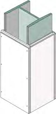
70 Chapter 3: Structural Steel - Timber Column Cladding Assessment Report CC TIMBER CLADDING When exposed to fire, most softwoods char at about 0.66mm/minute and most hardwoods at about 0.5mm/minute. The fire performance of a timber structural element will obviously depend on these charring rates and the loadbearing capacity of the residual timber. If the calculated residual timber is inadequate, Promat can offer various solutions normally using Promat SUPALUX or Promat VERMICULUX encasements. Please contact the Promat Technical Services Department for more details. TECHNICAL DATA 1. Concrete or timber column. 2. Promat SUPALUX or Promat VERMICULUX board, thickness is determined by fire resistance required and properties of the section to be encased. 3. Fixings into timber could consist of nails or screws, the length of which is determined by the type of timber and the duration of the fire resistance, please consult Promat Technical Services Department. 4. Where protection thickness is greater than 15mm, the boards can be edge fixed to each other avoiding the necessity of fixing to the concrete or timber column. Fixings should penetrate the substrate a minimum of 30mm. Fig Installation Method - Cladding to timber column. 112
. Voids at Compartment Walls Voids must be filled on beams that are part of a compartment wall, otherwise the integrity and insulation criteria of the wall will be breached.")
71 Chapter 3: Structural Steel - Design Considerations COMPOSITE DECKS When encasing steel beams supporting composite decks, it is in many cases unnecessary to fill the voids above the top flange of the beam (see table below). Voids at Compartment Walls Voids must be filled on beams that are part of a compartment wall, otherwise the integrity and insulation criteria of the wall will be breached. Voids may only be left unfilled on beams that do not form part of a compartment wall. For decks with the profile running parallel to beams no special recommendations are made for spray applied materials but, for board protection, the boards should be taken past the edge of the flange to abut the underside of the deck. Voids may be left unfilled where specified see table below Fig Table 3bl. Recommendations for beams assessed at 550ºC or 620ºC Trapezoidal Deck Beam type Fire protection on beam Fire resistance (minutes) Up to Over 90 Composite Materials assessed No increase in thickness Increase thickness by 10% Fill voids at 550ºC or assess thickness using A/V increased by 15%* Composite Materials assessed Increase thickness by 20% Increase thickness by 30% Fill voids at 620ºC or assess thickness using or assess thickness using A/V increased by 30%* A/V increased by 50%* Non-composite All types Fill voids above the flange * The least onerous option may be used Dovetail Decks Beam type Fire protection on beam Up to Over 90 Any All types Voids may be left unfilled for all periods of fire resistance NOTE 1: The assessed at temperature relates to that used in the performance assessment document (assessment) for beams subjected to maximum design stress as defined in BS : 2000 Structural Use of Steel in Building: Part 1 Code of Practice for Design, for the required fire resistance period. NOTE 2: Where such assessment temperatures exceed 550ºC, it is appropriate to use the 620ºC value when defining requirements, these to be applied to the thicknesses derived for the fully stressed beam(s). 113
PROMAtect 50 Structural steel. progressivematerials.com.au
 PROMAtect 50 Structural steel 08 9445 8300 info@progressivematerials.com.au progressivematerials.com.au STRUCTURAL STEEL FIRE PROTECTION PROMATECT 50 Cement Bound Matrix Board General Information 3 Definition
22 The Lowry Centre, Salford
 The Lowry Centre, Salford Glasroc F fire protection solutions Glasroc F board products FireCase GypWall CLASSIC 7 FireWall 88 Timber stud 9 GypWall CURVE 96 GypWall SECURE 99 BlastWall 0 FlameLyner 0 Cavity
Method Statement FM MS 09 SSCB
 FMFM FM Method Statement FM MS 09 SSCB Fire Protection of structural steelwork with the FireMaster Blanket Structural Steel PFP system in accordance with the EU CPR English Rev 1: March 2018 FM CONTENTS
PARTITIONS & EXTERNAL WALLS 5
 PARTITIONS & EXTERNAL WALLS INTERNAL PARTITIONS CONVERSION OF EXTERNAL WALL TO INTERNAL WALL TECHNICAL DATA 30 minutes fire rating, integrity and insulation in accordance with the criteria of BS 7: Part
The Passive Fire Protection Handbook
 The Passive Fire Protection Handbook The UK s comprehensive guide to passive fire protection Chapter Ceilings, Floors and Roofs AUGUST 0 The Passive Fire Protection Handbook Contents Chapter : Introduction
PROMATECT 50 Protection For Structural Steelwork
 Protection For Structural Steelwork Contents PROMATECT 50 Cement Bound Matrix Board General Information / Definition & Calculations For 2 Calculation of Hp/A Values 4 PROMATECT 50 Column Cladding 5 PROMATECT
STEEL DESIGNERS MANUAL
 STEEL DESIGNERS MANUAL SIXTH EDITION The Steel Construction Institute Edited by Buick Davison Department of Civil & Structural Engineering, The University of Sheffield Graham W. Owens Director, The Steel
STEEL STRUCTURAL SYSTEMS
 STEEL STRUCTURAL SYSTEMS Steel elements are of two basic types: Structural steel shapes are formed into their final shapes by hot-rolling. This method produces such common elements as wide flange sections,
Fire resistance of steel framed buildings 2003 edition
 Corus Construction & Industrial Fire resistance of steel framed buildings 2003 edition Contents 4 Section 1 - The Building Regulations and structural fire resistance 4 England and Wales 6 Scotland 7 Northern
1. Structural Steel Sections Structural steel sections can be classified into various groups according to their shapes.
 1 Structural Steelwork 1. Structural Steel Sections Structural steel sections can be classified into various groups according to their shapes. A steel section is designated by the serial size in millimeters
PASSIVE FIRE PROTECTION SYSTEMS Application & Technical Manual: Cavity & Smoke Barriers, Parapet & Spandrel Walls
 PASSIVE FIRE PROTECTION SYSTEMS Application & Technical Manual: Cavity & Smoke Barriers, Parapet & Spandrel Walls For Promat Asia Pacific Organisation February 0 PASSIVE FIRE PROTECTION SYSTEMS Application
YELLOW BOOK. Fire protection for structural steel in buildings 4 th Edition
 YELLOW BOOK Fire protection for structural steel in buildings 4 th Edition Association for Specialist Fire Protection Kingsley House, Ganders Business Park, Kingsley, Bordon, Hampshire GU35 9LU, United
The Association for Specialist Fire Protection
 The Association for Specialist Fire Protection Structural fire protection, Compartment Wall Penetrations and Firestopping Niall Rowan Technical Officer Association for Specialist Fire Protection Structural
FIRE PROTECTION. GTEC Shaftwall systems 244 GTEC Shaftwall Stairwell systems 248 GTEC Horizontal Shaftwall systems 249 GTEC Encasement systems 250
 FIRE PROTECTION GTEC Shaftwall range uses a specially designed system to protect voids and shafts in buildings. It resists pressure changes and enables installation from one side of the shaft only. GTEC
PROMATECT 250 Structural Steel Fire Protection
 PROMATECT 250 Structural Steel Fire Protection www.promat.com.au Solely for distribution in Australia CONTENTS PROMATECT 250 PROMAXON MINERAL BOARD 1.1 Autoclaved matrix engineered mineral board 3 1.2
Structural Performance of Long-Span Composite Truss and Beam Systems in Fire
 Structural Performance of Long-Span Composite Truss and Beam Systems in Fire *Seng-Kwan Choi 1), Ian Burgess 2) and Roger Plank 3) 1), 2) Department of Civil & Structural Engineering, University of Sheffield,Sheffield
Metal Web Floor System
 Metal Web Floor System Contents Contents Introduction and benefits 3 easi-joist definitions 4 easi-joist webs 5-6 Mechanical services 7 Loading and design 8 Floor stiffness 9 Internal non-loadbearing wall
EUROPEAN ORGANISATION FOR TECHNICAL APPROVALS
 E TA TECHNICAL REPORT Fire Resistance Tests for Cavity Barriers TR 31 Edition October 2008 EUROPEAN ORGANISATION FOR TECHNICAL APPROVALS EOTA TECHNICAL REPORT TR 031 Fire Resistance Tests for Cavity Barriers
Title: The Fire Resistance Performance of PRT and PRC, Side and Centre-Opening, Vandal Resistant, Lift Landing Doorsets. WF Assessment Report No:
 assessment report Title: The Fire Resistance Performance of PRT and PRC, Side and Centre-Opening, Vandal Resistant, Lift Landing Doorsets WF Assessment Report No: 183968A Prepared for: Klefer SA Kilkis
Responsibility Check List Sheet Item Description Responsibility Additional
 Responsibility Check List Sheet Item Description Responsibility Additional A B C Sketch Brief Layout for the position of the mezzanine. Advise whether requirement to remove intermediate columns to provide
UL Design System HW-D-1012 continued
 UL System No. HW-D-1012 Assembly Ratings 1, 2 and 3 Hr (See Item 2) Nominal Joint Width 3 in. Class II and III Movement Capabilities 100% Compression or Extension Page 1 of 5 1. Floor Assembly The fire-rated
Technical Manual. The difference is.
 Technical Manual The difference is www.rlsd.com innovation, commitment, support. 2 www.rlsd.com For a service with a difference, choose Richard Lees Steel Decking, the UK specialist steel decking company
Metal Decking Specialists
 Metal Decking Specialists Technical Design. Manual Manufacture. and Guidance Installation. Notes Contents Introduction 03 Introduction 04 SMD Product Selector Technical and Design Support 05 How can SMD
Loss Prevention Standard
 . Loss Prevention Standard LPS 1107: Issue 1.2 passive fire protection systems for structural steelwork This Loss Prevention Standard is the property of BRE Global Ltd. and is made publicly available for
PROMATECT fi 250 PROMAXON fi Technology Steelwork Fire Protection
 PROMATECT fi 250 PROMAXON fi Technology Steelwork Fire Protection A NEW GENERATION OF FIRE PROTECTION BOARDS PROMATECT fi 250 PROMAXON fi Technology Steelwork Fire Protection 01/02 PROMATECT fi 250 is
Good Morning everybody
 Good Morning everybody A discussion of fire scenarios and models for steel framed enclosed multi-storey balconies. Gordon Cooke International Fire Safety Consultant ( Formerly Visiting Professor, School
Structural Steel Products UK & Ireland. Multideck Technical Handbook
 Structural Steel Products UK & Ireland Multideck Technical Handbook 2 Structural Steel Products Multideck Multideck Structural Steel Products 3 4 Structural Steel Products Multideck Contents Multideck
GypLyner IWL Independent wall lining system
 Independent wall lining system Photograph courtesy of Philip Brier 0 Independent wall lining system independent wall lining is a lightweight, nonloadbearing drylining which is erected independently of
The Steel Construction Institute
 Version Date of Issue Purpose Author Technical Reviewer Approved 1 21 Apr 08 Issued to client LPN WIS BAB 2 3 The Steel Construction Institute REPORT TO CORUS CSD SLIMFLOR COMPENDIUM DOCUMENT RT1147 VERSION
The difference is Guidance for the preparation of Deck Manufacturing Schedules
 The difference is Guidance for the preparation of Deck Manufacturing Schedules innovation, commitment, support. 2 Guidance for the preparation of Deck Manufacturing Schedules Minimum Requirements for Schedule
Union County Vocational - Technical Schools Scotch Plains, New Jersey
 SECTION 092216 - NON-STRUCTURAL METAL FRAMING PART 1 - GENERAL 1.1 RELATED DOCUMENTS A. Drawings and general provisions of the Contract, including General and Supplementary Conditions and Division 01 Specification
PROMAtect h concrete upgrade Concrete and brick walls
 PROMAtect h concrete upgrade Concrete and brick walls 08 9445 8300 info@progressivematerials.com.au progressivematerials.com.au Concrete Upgrading Systems Index 112 Type of System Increase of Concrete/brick
3.4.2 DESIGN CONSIDERATIONS
 3.4.2 DESIGN CONSIDERATIONS Formwork Where Flatdeck sheet is used as formwork, the profile provides resistance to wet concrete (G) and construction loads (Q). Maximum formwork spans given in Section 3.4.4.1
Technical Guidance Note
 Technical Guidance Note THE BUILDING REGULATIONS 2004 EDITION ENGLAND AND WALES REQUIREMENT A3 DISPROPORTIONATE COLLAPSE 1. INTRODUCTION (a) This technical guidance note outlines NHBC s interpretation
Design of Column Base Plates
 Design of Column Base Plates Typical column bases, as shown below, consist of a single plate fillet welded to the end of the column and attached to the foundation with four holding down bolts. The bolts
Assessment Number BTC 16422FA
 Assessment Number BTC 16422FA A FIRE TEST ASSESSMENT TO BS EN 1364-1:1999 ON A 5M GYPWALL CLASSIC PARTITION OF 92 S 50 STUDS INCORPORATING A DOUBLE LAYER 15mm GYPROC SOUNDBLOC AND ISOVER APR 1200 IN THE
MATERIALS. Moment-resisting Frames. Key Words Historical steelwork, old steelwork, retrofit, appraisal, rehabilitation, assessment,
 Properties and Assessment of Historical Structural Steelwork Author: Kevin Cowie Affiliation: Steel Construction New Zealand Inc. Date: 3 rd July 2009 Ref.: MAT1005 MATERIALS Key Words Historical steelwork,
BISON PRECAST FLOORING SPECIFICATION
 BISON PRECAST FLOORING SPECIFICATION 1.0 SCOPE OF THE SPECIFICATION 1.01 Relates to: This specification covers the design, manufacture and associated site work of the following types of floors:- Hollowcore
GypWall AUDIO The ultimate sound insulating wall system
 The ultimate sound insulating wall system Cineworld, Ilford 8 The ultimate sound insulating wall system is a non-loadbearing, twin frame high performance wall system that provides exceptionally high levels
Loss Prevention Standard
 Loss Prevention Standard LPS 1132: Issue 4.2 Requirements and tests for LPCB approval of wall and This Loss Prevention Standard is the property of BRE Global Ltd. and is made publicly available for information
RH & RV CAVITY BARRIERS
 RH & RV CAVITY For use in external envelope or fabric of buildings SIDERISE RH OPEN STATE HORIZONTAL AND RV VERTICAL CAVITY BARRIER RANGE REPRESENT THE DEFAULT CHOICE FOR MARKET-LEADING, HIGH-PERFORMANCE
Electrical & Mechanical Services Enclosures - Designer Selector Table
 Designer Selector Table 8 Electrical & Mechanical Services Enclosures Integrity & Insulation Product Fire Rating Collar Size Mineral Wool VICUCLAD or VICUTUBE 0mm thick 0/0/0 80mm x 0mm thick mm x kg/m
Pre-schematic Considerations. Who. What. Where
 Who What Where Who, What & Where Who are the users? Church School Manufacturers Researchers Who, What & Where What is the purpose? Fellowship Teaching Manufacturing Production Who, What & Where Location,
Structural Products. Multideck 50-V3 Galvanised Steel Floor Decking System
 Structural Products & Systems Multideck Multideck 50-V3 Galvanised Steel Floor Decking System Meadowhall Extension, Sheffield UK. Image courtesy of MSW (UK) Ltd. 2 Introduction Structural Products & Systems,
CHAPTER 1 INTRODUCTION
 CHAPTER 1 INTRODUCTION 1.0. GENERAL Modern civilization relies upon the continuing performance of civil engineering infrastructure ranging from industrial building to power station and bridges. For the
CERTIFICATE OF APPROVAL No CF 422 PROMAT UK LTD
 CERTIFICATE OF APPROVAL No CF 422 This is to certify that, in accordance with TS00 General Requirements for Certification of Fire Protection Products The undermentioned products of The Sterling Centre,
Contents. 01 Introduction Key Design Factors. 03 Floor Systems. 04 Special Floor Systems Beam Connections.
 Best Practice in Steel Construction - Commercial Buildings Contents The Steel Construction Institute (SCI) develops and promotes the effective use of steel in construction. It is an independent, membership
fermacell AESTUVER Fire-protection board
 fermacell AESTUVER Fire-protection board European Technical Assessment Datum: 30.09.2014 European Technical Assessment ETA-11/0458 of 30 September 2014 General Part Technical Assessment Body issuing the
Loss Prevention Standard
 Loss Prevention Standard LPS 1208: Issue 2.2 This Loss Prevention Standard is the property of BRE Global Ltd. and is made publicly available for information purposes only. Its use for testing, assessment,
PASSIVE FIRE PROTECTION SYSTEMS Application & Technical Manual: Ductwork
 PASSIVE FIRE PROTECTION SYSTEMS Application & Technical Manual: Ductwork For Promat Asia Pacific Organisation February 0 Ductwork General Information i Steel duct claddings inside the Changi Water Reclamation
ISSUE A Code Change # 2 Class 3 and Class 4 Buildings
 ISSUE A Code Change # 2 Class 3 and Class 4 Buildings (new) Section 1604.9 Disproportionate Collapse. Design for structural integrity of new buildings to protect against disproportionate collapse shall
Thesis Proposal Structural Redesign / Cost, Schedule and Coordination Analysis / Architectural Impact
 Thesis Proposal Structural Redesign / Cost, Schedule and Coordination Analysis / Architectural Impact Executive Summary:, located in Pigeon Forge, Tennessee, is designed as a multifunctional space and
VARIOUS TYPES OF SLABS
 VARIOUS TYPES OF SLABS 1 CHOICE OF TYPE OF SLAB FLOOR The choice of type of slab for a particular floor depends on many factors. Economy of construction is obviously an important consideration, but this
Masonry and Cold-Formed Steel Requirements
 PC UFC Briefing September 21-22, 2004 Masonry and Cold-Formed Steel Requirements David Stevens, ARA Masonry Requirements Composite Construction Masonry is often used in composite construction, such as
ColumnClad System. Rigid fire protection solutions for structural steel columns and beams
 ZERO ODP ZERO GWP CI/SfB Rf7 July 05 (replaces September 04 issue) OZONE DEPLETING POTENTIAL GLOBAL WARMING POTENTIAL Construction type Structural Steelwork Rockwool supports FIRAS accredited installers
CO3. Steel encasements C03. Introduction - FireCase 01/12/2017 GypLyner encase 11/05/2017. Introduction Steel encasements
 ! This section includes updated information, added since it was first published in ecember 05. Section Last updated Introduction - FireCase 0//07 GypLyner encase /05/07 Introduction Steel encasements C03
151 First Side. Technical Assignment 2 November 16 th, William J. Buchko. AE 481w Senior Thesis The Pennsylvania State University
 November 16 th, 2007 William J. Buchko AE 481w Senior Thesis The Pennsylvania State University Thesis Advisor: Kevin Parfitt Table of Contents Executive Summary... 3 Structural System Overview Foundation...
Anchor bolts ASTM F1554, Gr. 36 Wide flange beams ASTM A992, Fy = 50 ksi Misc. structural steel ASTM A36, Fy = 36 ksi
 STRUCTURAL NOTES MATERIAL STRENGTHS Structural Steel Reinforcing Steel Concrete Masonry Structural Lumber Anchor bolts ASTM F1554, Gr. 36 Wide flange beams ASTM A992, Fy = 50 ksi Misc. structural steel
Part 6 Superstructure (excluding roofs) Chapter 6.5. Steelwork
 Chapter 6.5. Steelwork") Part 6 Superstructure (excluding roofs) hapter ONTENTS SOPE DESIGN lause Page Design standards D1 1 Structural design D 1 Padstones D3 1 This hapter gives guidance on meeting the Technical Requirements
Part 6 Superstructure (excluding roofs) hapter ONTENTS SOPE DESIGN lause Page Design standards D1 1 Structural design D 1 Padstones D3 1 This hapter gives guidance on meeting the Technical Requirements
DIVISION 5 METALS SECTION COLD-FORMED METAL FRAMING
 DIVISION 5 METALS SECTION 05 40 00 PART 1 - GENERAL 1.1 RELATED DOCUMENTS A. Drawings and general provisions of the Contract, including General and Supplementary Conditions and Division 01 Specification
Insulating Cellular Concrete Steel Joists Painting. A. America Society for Testing and Materials (ASTM):
:") SECTION 05120 STRUCTURAL STEEL PART 1 GENERAL 1.01 SUMMARY A. Related Sections: 1. 03342 - Insulating Cellular Concrete. 2. 05210 - Steel Joists. 3. 09900 - Painting. 1.02 REFERENCES A. America Society
SECTION 05120 STRUCTURAL STEEL PART 1 GENERAL 1.01 SUMMARY A. Related Sections: 1. 03342 - Insulating Cellular Concrete. 2. 05210 - Steel Joists. 3. 09900 - Painting. 1.02 REFERENCES A. America Society
FORMDECK. constructions. constructions
 FORMDECK constructions constructions Introduction Formdeck300 (FD300) is a very efficient and durable permanent metal tray formwork, reinforcement and ceiling system used for suspended concrete slab construction.
Contents. Tables. Notation xii Latin upper case letters Latin lower case letters Greek upper case letters Greek lower case letters. Foreword.
 Tables x Notation xii Latin upper case letters Latin lower case letters Greek upper case letters Greek lower case letters xii xiv xvi xvi Foreword xviii 1 Introduction 1 1.1 Aims of the Manual 1 1.2 Eurocode
STEEL BUILDINGS IN EUROPE. Multi-storey Steel Buildings Part 9: Description of simple connection resistance calculator
 STEEL BUILDINGS IN EUROPE Multi-storey Steel Buildings Part 9: Description of simple connection resistance calculator Multi-Storey Steel Buildings Part 9: Description of simple connection resistance calculator
SIDERISE TW fire stops for profiled decks
 CONSTRUCTION: TW FIRE STOPS Version 1 : April 2015 SIDERISE TW fire stops for profiled decks Semi-rigid mineral wool insulation designed for use in small/irregular shaped cavities in ceiling voids, to
Demountable suspended grid ceiling system
 C06 Floors and ceilings CasoLine quicklock grid t5 CasoLine quicklock grid t5 Demountable suspended grid ceiling system All our systems are covered by SpecSure when using genuine Gyproc and Isover products
An introduction to Part L U-values
 December 2010 An introduction to Part L This document provides a wide selection of building fabric constructions with their associated. It has been produced a support to our publication An introduction
North Shore at Canton Baltimore, MD Beau Menard Technical Report 1
 North Shore at Canton Baltimore, MD Beau Menard Technical Report 1 Structural Schneider 10/05/05 Structural Concepts Executive Summary North Shore at Canton is a 4 story town home and parking garage structure
Independent twin frame high performance acoustic separating wall system
 C04 Partitions Independent twin frame high performance acoustic separating wall system All our systems are covered by SpecSure when using genuine Gyproc and Isover products is a lightweight, non-loadbearing
Promaseal pillows. progressivematerials.com.au
 Promaseal pillows 08 9445 8300 info@progressivematerials.com.au progressivematerials.com.au PROMASEAL PILLOWS VARIOUS PENETRATION SEALS IN FLOORS, WALLS & PARTITIONS SP 81.18 82.18 PROMASEAL Pillows are
LPI 56 Technical Guide
 LPI 56 Technical Guide Floor & Roof Applications Product Specifications & Design Values 2 Floor Tables 3 Uniform Floor Load (PLF) Tables: Simple s 4 Uniform Floor Load (PLF) Tables: Continuous s 5 Uniform
BEAMCLAD SYSTEMS. Fire protection solutions for structural steel & soffit protection
 BEAMCLAD SYSTEMS Fire protection solutions for structural steel & soffit protection FIREPRO BEAMCLAD SYSTEMS ROCKWOOL BEAMCLAD systems boast a complete tool-box of options. They offer contractors simple
SEISMIC BEHAVIOR AND DESIGN OF STEEL SHEAR CONNECTIONS WITH FLOOR SLABS
 SEISMIC BEHAVIOR AND DESIGN OF STEEL SHEAR CONNECTIONS WITH FLOOR SLABS Judy LIU 1 And Abolhassan ASTANEH-ASL 2 SUMMARY The 1994 Northridge earthquake raised many questions regarding welded steel moment
Multideck 146. Contents
 Contents Specification and Design 55 Load Tables 57 Fire Performance 60 Sound Attenuation 63 Concrete Volume Savings composite steel deck is optimised to minimise the concrete volumes on longer spans providing
CERTIFICATE OF APPROVAL No CF 5073 LEMINAR AIR CONDITIONING INDUSTRIES L.L.C.
 CERTIFICATE OF APPROVAL No CF 5073 This is to certify that, in accordance with TS00 General Requirements for Certification of Fire Protection Products The undermentioned products of PO Box 33539, Dubai,
Crossroads at Westfields Building II
 Crossroads at Westfields Building II Chantilly, Va STEPHEN LUMPP Structural option Faculty Consultant: Dr. Andres Lepage Technical Report 2 EXECUTIVE SUMMARY This report is a study of alternate floor systems
Pro-Con Structural Study for Alternative Floor Systems October 27, 2004
 Ismail Al-Hadhrami Structural Option Faculty Consultant: Dr. Thomas Boothby Agricultural Hall and Annex East Lansing, MI Pro-Con Structural Study for Alternative Floor Systems October 27, 2004 Executive
GypWall AUDIO The ultimate cinema wall system
 The ultimate cinema wall system 9 Vox Cinemas, Muscat City Centre - Sultanate of Oman 7 0 R w db 0 0 mins is a non-loadbearing, twin frame high performance wall system that provides exceptionally high
Nortrax Section David Manchester Road, Ottawa NON-STRUCTURAL METAL FRAMING 16 May 2014 Page 1
 16 May 2014 Page 1 PART 1 GENERAL 1.1 DESCRIPTION This section specifies steel studs wall systems, shaft wall systems, ceiling or soffit suspended or furred framing, wall furring, fasteners, and accessories
FireCase. Frameless structural steel encasement system. FireCase.
 Frameless structural steel encasement system frameless encasement system provides a high quality cladding to structural steel, and offers up to 10 minutes fire protection. The system affords protection
The Edge Protection Federation Containment Systems Product Specification, Test Methods
 The Edge Protection Federation Containment Systems Product Specification, Test Methods Revision 2 August 2016 This Standard defines how the Edge Protection Federation defines Containment. This document
Following contains common verbiage found in major model building codes and has been edited for the purpose of inclusion on this CD.
 Following contains common verbiage found in major model building codes and has been edited for the purpose of inclusion on this CD. Included are selected sections of codes taken directly from: 1997 Uniform
Structural Redesign Gravity System
 Redesign Gravity System Design Considerations A composite floor system was used for this design to maximize the efficiency of the material being used. This type of system requires less material and provides
SECTION NON-STRUCTURAL METAL FRAMING
 SECTION 09 22 16 PART 1 - GENERAL 1.1 DESCRIPTION A. This section specifies steel studs wall systems, shaft wall systems, ceiling or soffit suspended or furred framing, wall furring, fasteners, and accessories
fifteen design for lateral loads Lateral Load Resistance Load Direction Lateral Load Resistance
 APPLIED ARCHITECTURAL STRUCTURES: STRUCTURAL ANALYSIS AND SYSTEMS DR. ANNE NICHOLS FALL 2013 lecture fifteen design for lateral loads Lateral Load Resistance stability important for any height basic mechanisms
CD 360 Use of Compressive Membrane Action in Bridge Decks
 Design Manual for Roads and Bridges Highway Structures & Bridges Design CD 360 Use of Compressive Membrane Action in Bridge Decks (formerly BD 81/02) Revision 1 Summary This document provides requirements
Part E robustdetails. robustdetails. January 2018 Update Pack
 Part E Pack Dear Colleague, The first Update Pack of the year, and the first welcome from me as Chief Executive. Although new to the role, I have been with the company for nine years with responsibility
GypLyner UNIVERSAL Concealed grid ceiling lining system
 Concealed grid ceiling lining system The Sage, Gateshead 9 Concealed grid ceiling lining system ceiling is a general purpose ceiling lining system suitable for most internal applications. It is used in
Title: The Fire Resistance Performance of EI60, Side and Centre-Opening Lift Landing Doorsets. WF Assessment Report No: /A.
 Title: The Fire Resistance Performance of EI60, Side and Centre-Opening Lift Landing Doorsets WF Assessment Report No: 167510/A Prepared for: Klefer A.E. Kilkis Industrial Area 61100 Stavroxori. Grecia
Title: The Fire Resistance Performance of PRT and PRC, Side and Centre-Opening Lift Landing Doorsets. WF Assessment Report No: Prepared for: Klefer SA
 Exova Warringtonfire Holmesfield Road Warrington WA1 2DS United Kingdom T : +44 (0) 1925 655 116 F : +44 (0) 1925 655 419 E : warrington@exova.com W: www.exova.com Title: The Fire Resistance Performance
The extra strong, extra durable, sound resistant system that you can direct fix to
 C0 Partitions The extra strong, extra durable, sound resistant system that you can direct fix to All our systems are covered by SpecSure when using genuine Gyproc and Isover products gyproc.ie Utilising
Duct Wrap Flexible Wraps
 Design No. 3MU/ 60-01 December 23, 2010 VENTILATION DUCT PROTECTION 3M Company 3M Fire Barrier Duct Wraps: 615 and 615+ 3M Fire Barrier Sealants: Water-Tight 1000-NS Silicone, Water-Tight 1003-SL Silicone
Displacement Based Assessment and Improvement of a Typical New Zealand Building by an Average Engineer
 Displacement Based Assessment and Improvement of a Typical New Zealand Building by an Average Engineer M.L. Grant LGE Consulting, Masterton 2016 NZSEE Conference ABSTRACT: The Radiohouse building is a
Early Thermal Cracking of Concrete
 THE HIGHWAYS AGENCY THE SCOTTISH OFFICE DEVELOPMENT DEPARTMENT Incorporating Amendment No.1, 1989 THE WELSH OFFICE Y SWYDDFA GYMREIG THE DEPARTMENT OF THE ENVIRONMENT FOR NORTHERN IRELAND Early Thermal
fifteen design for lateral loads Lateral Load Resistance Load Direction Lateral Load Resistance
 APPLIED ARCHITECTURAL STRUCTURES: STRUCTURAL ANALYSIS AND SYSTEMS DR. ANNE NICHOLS SPRING 2017 lecture fifteen design for lateral loads Lateral Load Resistance stability important for any height basic
Recommendations for additional fire protection of structural elements
 ANNEX 6 Recommendations for additional fire protection of structural elements 1 Scope This Annex contains a series of recommendations applicable to structural concrete structures which, for general fire
fifteen design for lateral loads Lateral Load Resistance Load Direction Lateral Load Resistance
 APPLIED ARCHITECTURAL STRUCTURES: STRUCTURAL ANALYSIS AND SYSTEMS DR. ANNE NICHOLS FALL 2014 lecture fifteen design for lateral loads Lateral Load Resistance stability important for any height basic mechanisms
Internal Partitions - Timber Studs Internal Partitions - Steel Stud
 Timber Studs PH Internal Partitions - Steel Stud / hour fire rating, integrity and insulation in accordance with the criteria of BS : Part and AS 0: Part. Nominal thickness of partition: mm PROMATECT -H
STRUCTURAL STEEL FIRE PROTECTION INTUMESCENT COATINGS SYSTEMS
 STRUCTURAL STEEL FIRE PROTECTION INTUMESCENT COATINGS SYSTEMS CHRIS PARTINGTON Passive Fire Protection Specialist AkzoNobel International Paint Australia AGENDA The types of fires and their behaviour Types
SECTION NON-STRUCTURAL METAL FRAMING
 PART 1 - GENERAL 1.1 DESCRIPTION SECTION 09 22 16 1. Use this section only for NCA projects. 2. Delete between //----// if not applicable to project. Also delete any other item or paragraph not applicable