Mid Rise Design: Opportunity and Implementation. Janelle Leafblad, PE
|
|
|
- Herbert Arnold
- 6 years ago
- Views:
Transcription


1 Mid Rise Design: Opportunity and Implementation Janelle Leafblad, PE
2 The Wood Products Council is a Registered Provider with The American Institute of Architects Continuing Education Systems (AIA/CES), Provider #G516. Credit(s) earned on completion of this course will be reported to AIA CES for AIA members. Certificates of Completion for both AIA members and non AIA members are available upon request. This course is registered with AIA CES for continuing professional education. As such, it does not include content that may be deemed or construed to be an approval or endorsement by the AIA of any material of construction or any method or manner of handling, using, distributing, or dealing in any material or product. Questions related to specific materials, methods, and services will be addressed at the conclusion of this presentation.
3 Course Description As increases in urban density become necessary to address growing populations, many building designers and developers are leveraging wood s ability to achieve multiple, simultaneous objectives. Wood is a code compliant solution to the challenge of how to cost effectively increase density while creating vibrant and sustainable communities. Yet many familiar with the design of two to four story wood structures are not aware that the International Building Code allows five stories and more of wood frame construction for residential uses such as student, senior and affordable housing, and for business, mercantile and military occupancies. Through an overview of design, detailing, and construction considerations, this presentation is intended to give architects and engineers the confidence to break into this growing market segment. Heights and areas will be discussed, including allowable increases, as will fire resistive design, detailing for performance, shrinkage, structural framing, acoustics, and fire rated assemblies.
4 Learning Objectives 1. In the context of a shift toward greater urban density, discuss how mid rise, wood frame construction meets housing needs while creating vibrant sustainable communities. 2. Discuss allowable construction types, occupancies, and building heights/stories/areas for wood frame mid rise buildings per the current International Building Code. 3. Identify fire resistance and protection requirements for wood frame wall assemblies in Type III and Type V buildings. 4. Examine detailing best practices to achieve performance requirements for acoustics, lateral bracing, shrinkage effects, and floor to wall interfaces.
5 Outline Need for Mid Rise Construction (Urban Densification) Mid rise Building Types/Configurations Maximizing Height & Area Fire Ratings & Requirements Structural Design & Detailing Considerations Shrinkage Considerations & Detailing Acoustic Requirements & Detailing Common Floor to Wall Detailing
6 Outline Need for Mid Rise Construction (Urban Densification) Mid rise Building Types/Configurations Maximizing Height & Area Fire Ratings & Requirements Structural Design & Detailing Considerations Shrinkage Considerations & Detailing Acoustic Requirements & Detailing Common Floor to Wall Detailing


7 Global Population Boom Global Population > 7 billion now 9.0 billion by % increase Urban Population 5.3 billion by % increase
8 Need for Sustainable Multi Family & Mixed Use Structures Economically Meet Urban Housing Needs Increase Environmental Responsibility These 2 items don t need to be in opposition Wood framing helps them work together!

9 Need for Sustainable Multi Family & Mixed Use Structures Mid Rise Wood Frame Construction provides a common ground for both How?

10 Mid Rise Construction Senior Living Apartments/Condos Mixed Use Student Housing Affordable Housing Hotels Where Wood is a viable option, it s likely the most appropriate choice.


11 Why Wood? Wood Costs Less Wood is Versatile Wood Meets Code Wood is Durable Wood is Renewable Using Wood Helps Reduce Your Environmental Impact Wood Products Play a Significant Role in Modern Economy

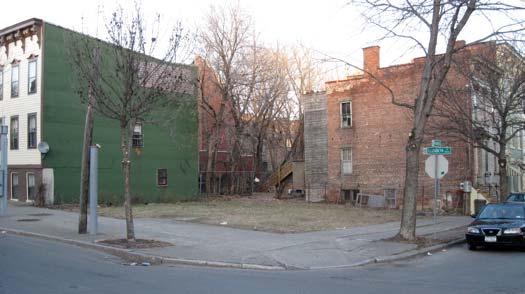
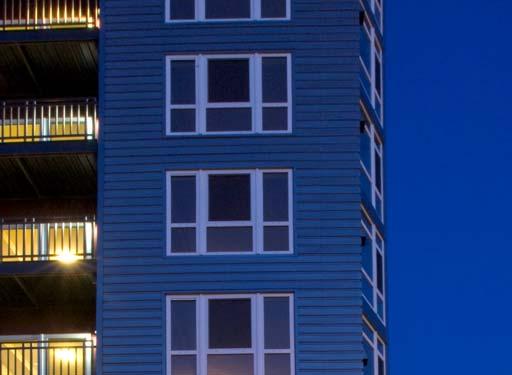
12 Urban Infill Development


13 Case Study: Wood Buildings Aim High AvalonBay Stadium Location: Anaheim, CA 251 Apts., 13K sf retail/restaurant Type III modified 50% of their projects are podium Semi balloon framed with 16 I joist at exterior walls Architect: Withee Malcolm Architects Engineer: VanDorpe Chou Associates Developer/Contractor: AvalonBay Communities Photo credit: Arden Photography


14 Carbon Case Study: High Density AvalonBay Stadium Anaheim, CA
15 Outline Need for Mid rise Construction (Urban Densification) Mid rise Building Types/Configurations Maximizing Height & Area Fire Ratings & Requirements Structural Design & Detailing Considerations Shrinkage Considerations & Detailing Acoustic Requirements & Detailing Common Floor to Wall Detailing


16 Seattle, WA College Park, MD Normal, IL Los Angeles, CA Atlanta, GA
17 Wood Mid Rise Construction How many stories can be wood framed in the IBC? Photo credit: Matt Todd & PB Architects


18 Marselle Condos, Seattle, WA M Photo credit: Matt Todd & PB Architects 6 stories for Offices, 5 stories for Residential + Mezzanine + Multi-Story Podium

19 Mid Rise vs. High Rise Definition IBC 202

20 Walk up/ Tuck Under First floor walk up units with private garage Benefits: Eliminates need for S 2 parking garage Can be all wood Least expensive overall but lowest densification rates


21 Wrap Around Walk up units surround parking structure Benefits: Enhanced security Centralized access to parking Visual appeal from street More expensive than walk/up tuckunder 5 story yields units/acre
22 Podium Multiple stories of wood over an elevated concrete deck Benefits: Increased number of stories Accommodates Mixed use occupancies Most expensive but can allow increased density
23 Podium 4 stories of residential over podium (parking or retail) units/acre Inman Park Condos, Atlanta, GA Davis & Church

24 Podium 5 stories over retail units/acre AvalonBay Stadium, Anaheim, CA VanDorpe Chou Associates Inman Park Condos, Atlanta, GA Davis & Church
25 Podium 5 stories over residential podium units/acre 16 Powerhouse, Sacramento, CA D&S Development LPA Sacramento


26 Mezzanine & Podium 5 stories with mezzanine + residential podium units/acre 120 Union, San Diego, CA Togawa Smith Martin
27 Outline Need for Mid rise Construction (Urban Densification) Mid rise Building Types/Configurations Maximizing Height & Area 1. Construction Types 2. Tabulate Areas & Stories 3. Allowable increases 4. Mezzanine & Special Design Provisions Fire Ratings & Requirements Structural Design & Detailing Considerations Shrinkage Considerations & Detailing Acoustic Requirements & Detailing Common Floor to Wall Detailing
28 Typical Mid rise Occupancy Hotels (R 1) Apartments (R 2) Condominiums (R 2) Student housing (R 2) Live/work units (R 2) Assisted living (R 4) Nursing homes (I 2) (B )Offices (A 2) Restaurants/cafeterias (A 3) Workout facilities (A 3) Meeting rooms (B )Offices (M) Shops (S 2) Parking (S 1) Storage
29 Mid Rise Construction Types Type III Exterior walls non combustible Interior elements any allowed by code Type V All building elements are any allowed by code Types III and V can be subdivided to A (protected) or B (unprotected) Type IV (Heavy Timber) Exterior walls non combustible Interior elements qualify as Heavy Timber More on fire ratings a little later
30 Mid Rise Construction Types Materials Protected Elements Less Protected Elements Unprotected Elements Non Combustible IA, IIA IB IIB Combustible Mixed Systems IIIA IIIB Heavy Timber IV Any Materials VA VB
31 IBC Building Valuation Data International Code Council, Feb 2015 Data R 2 Occupancy $ per Square Foot Primary Structural Wood Framing Allowed IA IB IIA IIB IIIA IIIB VA VB IBC Construction Type
32 Heights and Areas IBC Table 503
33 Type III Construction Exterior walls are of noncombustible materials and interior building elements are of any material. Fire Retardant Treated (FRT) wood is permitted in exterior walls of 2hr fire rating or less. Non combustible Exterior walls Fire Retardant Treated allowed Exterior walls if fire rating is 2hr or less Heavy Timber HT used in place of 1hr rating or less Untreated Lumber All interior elements
34 Step 1 Tabulated Height and Area Type IIA Type IIIA 65 (4) 65 (4) Occupancy IIA IIIA R 1 24,000 24,000 R 2 24,000 24,000
35 Step 1 Tabulated Height and Area Type IIB Type IIIB 55 (4) 55 (4) Occupancy IIB IIIB R 1 16,000 16,000 R 2 16,000 16,000

 40 (2)")

36 Step 1 Tabulated Height and Area Type VA Type VB 50 (3) 40 (2) Occupancy VA VB R 1 12,000 7,000 R 2 12,000 7,000
37 Height Modification IBC 504 IBC Where a building is equipped throughout with an approved sprinkler system maximum height is increased by 20 feet maximum number of stories is increased by one does not apply if using NFPA 13R sprinkler Can be combined w/ frontage area increase Can be combined w/ sprinkler area increase EXCEPT for I 2 occupancy of Type IIB, III and V construction and H occupancies or where sprinklers are used as substitution for 1hr fire resistance.
38 Automatic Sprinkler Increase Automatic sprinkler system increase..for Group R buildings equipped throughout with an approved automatic sprinkler system in accordance with Section , the value specified in Table 503 for maximum building height is increased by 20 feet (6096 mm) and the maximum number of stories is increased by one, but shall not exceed 60 feet ( mm) or four stories, respectively. Section references NFPA 13R sprinkler system. This 60, 4 story limitation does not apply when using NFPA 13 Sprinkler System
39 Area Modification IBC 506 Combining the building size benefits of sprinklers and frontage: (Equation 5 1) A a = A t + [A t x I f ] + [A t x I s ] A a = Allowable area per story (sq. ft.) A t = Tabular area per story (sq. ft.) (IBC Table 503) I f = Area increase factor due to frontage (IBC 506.2) I f max =.75 I s = Area increase factor due to sprinkler protection (IBC 506.3) I s =3 for 1 story, I s =2 for > 1 story 1 Story: Max Floor Area = 4.75x tabulated area >1 Story: Max Floor Area = 3.75x tabulated area


40 IBC Building Size Limits NFPA 13 IIIA Tabular Height Limits Increased Limits With NFPA 13 Sprinklers: IBC gives an allowable Heights and Area Increase
")
* R 1 72,000 +18,000 (max")


41 Step 2 Increased Height & Story Area Type IIA Type IIIA NFPA13 NFPA13 85 (5) 85 ** (5) Occupancy IIA (ft 2 )* IIIA (ft 2 )* R 1 72, ,000 (max frontage) 72, ,000 (max frontage) R 2 72, ,000 (max frontage) 72, ,000 (max frontage) *Areas reflect PER STORY max. Total building max may limit area further. **ASCE limits wood shear wall seismic systems to 65 in height in SDC D,E,F
* IIIB (ft 2 )* R 1 48,000 +12,000(max frontage) 48,000 +12,000(max frontage) R 2 48,000")

42 Step 2 Increased Height & Story Area Type IIB Type IIIB NFPA13 NFPA13 75 (5) 75 ** (5) Occupancy IIB (ft 2 )* IIIB (ft 2 )* R 1 48, ,000(max frontage) 48, ,000(max frontage) R 2 48, ,000(max frontage) 48, ,000(max frontage) *Areas reflect PER STORY max. Total building max may limit area further. **ASCE limits wood shear wall seismic systems to 65 in height in SDC D,E,F
43 Type IIIB for R Occupancy Horizontal assemblies separating dwelling units in the same building and horizontal assemblies separating sleeping units in the same building shall be a minimum of 1 hour fireresistance rated construction. EXCEPTION Dwelling unit and sleeping unit separations in buildings of Type IIB, IIIB and VB construction shall have fire resistance ratings of not less than 1 /2 hour in buildings equipped throughout with an automatic sprinkler system in accordance with Section
 60 (3) Occupancy VA (ft 2 )* VB (ft 2 ) R 1")
 21,000 +5,250(max frontage) *Areas")

44 Step 2 Increased Height & Story Area Type VA Type VB NFPA13 NFPA13 70 ** (4) 60 (3) Occupancy VA (ft 2 )* VB (ft 2 ) R 1 36,000 +9,000(max frontage) 21,000 +5,250(max frontage) R 2 36,000 +9,000(max frontage) 21,000 +5,250(max frontage) *Areas reflect PER STORY max. Total building max may limit area further. **ASCE limits wood shear wall seismic systems to 65 in height in SDC D,E,F
 Occupancy IIIA (ft 2 )* IV (ft 2 )* B 85,500 +21,375(max frontage) 108,000")

45 Opportunity for Office Occupancy (B) Type IIIA Type IV NFPA13 NFPA13 85 ** (6) 85 ** (6) Occupancy IIIA (ft 2 )* IV (ft 2 )* B 85, ,375(max frontage) 108, ,000(max frontage) *Areas reflect PER STORY max. Total building max may limit area further. **ASCE limits wood shear wall seismic systems to 65 in height in SDC D,E,F
46 IBC Building Size Limits Residential (R1, R2, and R4) Occupancies Construction Type IIIA IIIB VA VB Allowable Limit Stories Height (ft) Building Area/Story (ft 2 ) 24k 16k 12k 7k Total Building Area* (ft 2 ) 72k 48k 36k 14k * Assuming max stories built IBC 2012 Table 503 Tabular Values
47 IBC Building Size Limits with Sprinkler Residential (R1, R2, and R4) Occupancies Type IIIA Construction Allowable Limit Table 503 NPFA 13 NPFA 13 Frontage? Stories Height (ft) Building Area/Story (ft 2 ) 24k 24k 72k 90k Total Building Area* (ft 2 ) 72k 72k 216k 270k IBC 2012 Section * Assuming max stories built per IBC 506.4? Maximum frontage increase possible
48 Maximum Building Area Single Occupancy Area determination Two stories above grade: Maximum Building Area = A a x 2 Three stories or more above grade: Maximum Building Area = A a x 3 No Story shall exceed A a Exceptions Unlimited area buildings Buildings with NFPA 13R sprinkler system A a Allowable Area PER STORY
49 Step 3 Max Building vs. Story Areas Type IIIA Type VA NFPA13 NFPA13 85 ** (5) 70 ** (4) Occupancy IIIA VA Story Area 72, ,000 (max frontage) 36,000 +9,000(max frontage) Building Area 216, ,000 (max frontage) 108, ,000 (max frontage) **ASCE limits wood shear wall seismic systems to 65 in height in SDC D,E,F


 IIIA")
 Story Area 72,000")
 12,000")
")
")

50 Step 3 Max Building vs. Story Areas Type IIIA NFPA13 Type IIIA Or Type VA NFPA13R 85 ** (5) 60 ** (4) Occupancy IIIA (NFPA 13) IIIA (NFPA 13R) VA (NFPA 13R) Story Area 72,000 (3x tabulated) 24,000 (=tabulated) 12,000 (=tabulated) Building Area 216,000 (3x story) 96,000 (4x story) 48,000 (4x story) **ASCE limits wood shear wall seismic systems to 65 in height in SDC D,E,F
 5 story Type III wood frame over slab on grade (2) 4 stories of wood over 1 story concrete")
 Architect: Cooper Carry, The Preston Partnership Engineer: Ellinwood + Machado, Pruitt Eberly Stone")
51 Case Study: Innovations in Wood Emory Point Location: Atlanta, GA 3 buildings complete Luxury Apt., retail, restaurants (1) 5 story Type III wood frame over slab on grade (2) 4 stories of wood over 1 story concrete podium 35% savings $14/sf (wood concept) $22/sf (PT conc. Slab and frame) Architect: Cooper Carry, The Preston Partnership Engineer: Ellinwood + Machado, Pruitt Eberly Stone Contractor: Fortune Johnson Contracting Completed: 2012 Photo credit: Gables Residential


52 Case Study: Stella Apartments Stella Apartments Location: Marina Del Ray, CA 244 Apts., 650K sf total (2 bldgs) Type IIIA and VA construction Panelized wood framing saved 1 2 months construction time and $200,000 Architect: Design ARC. Los Angeles, CA Photos: Lawrence Anderson,
53 Mixed Use Occupancy Located at woodworks.org design tools online calculators Heights and Areas Calculator
54 Step 4 Addition of Mezzanine An intermediate level or levels between the floor and ceiling of any story and in accordance with IBC Section 505. Occupancy IIIA (NFPA 13) Type IIIA Story Area Building Area 72,000* (3x tabulated) 216,000 (3x story area) *Areas reflect PER STORY max. Total building max may limit area further. **ASCE limits wood shear wall seismic systems to 65 in height in SDC D,E,F 85 ** (5+ mez)
55 Mezzanines IBC 505 Not counted toward building area** or height if: Maximum 1/3 floor area of room or space where located Special egress provisions apply Must be open and unobstructed to room in which it s located (walls 42 allowed) Several exceptions Slightly different for equipment platforms **Does count toward fire area with regard to fire protection in Chapter 9


56 Case Study: Maximizing View and Value With Wood Marselle Condominiums Location: Seattle WA Type IIIA condo complex 5 1/2 stories of wood over 2 stories of concrete mezzanine added $250K cost but $1M in value 30% cost savings over concrete Time savings over steel Architect: PB Architects Engineer: Yu & Trochalakis Contractor: Norcon, NW Completed: 2009 Photo Credit: Matt Todd Photography


57 Step 4 Horizontal Building Separation Horizontal Assembly = a fire resistance rated floor or roof assembly of materials designed to restrict the spread of fire in which continuity is maintained Type IIIA 85 ** (5+ mez) 85 Drs Jullian and Raye Richardson Apts. San Francisco, CA David Baker Architect, Photo Credits: Bruce Damonte **ASCE limits wood shear wall seismic systems to 65 in height in SDC D,E,F
58 Horizontal Building Separation Considered separate buildings above and below for purposes of area calculations if: overall height is still limited to min of either building 3hr rated horizontal assembly Building below is one story above grade Building below is Type 1A with sprinklers Enclosures penetrating horizontal assembly are 2hr rated occupancy above is A, B, M, R or S occupancy below is A, B, M, R or S 2 The Flats at ISU, Normal, IL OKW Architects Precision Builders & Associates

59 IBC Podium Provisions 3Hr Type IA 5 story Type III Building 5 story Type III Building On Top of a Type IA Podium Special Provisions for Podiums in IBC Increases allowable stories not allowable building height

60 Evolution of IBC Mixed Use Podium 3Hr Type IA IBC Section Upper Occupancy Lower Occupancy Podium Height S 2 Parking A, B, M, R or S A, B, M, R or S 2 Parking Any Except H 1 Story Multi Story IBC Provisions for Mixed Use podium have been evolving IBC will allow multiple podium stories above grade.
61 Parking Beneath Group R IBC Possibility of a Type IV podium where number of stories starts above parking when: Occupancy above is R and below is S 2 Lower floor is open Type IV parking with grade entrance Horizontal assembly between 1 st and 2 nd floor shall be Type IV Have 1 hr fire resistance rating when sprinklered Have 2 hr fire resistance rating when not sprinklered Overall height is still limited to occupancy 2Hr Type IV 5 story Type III Building On Top of a Type IV


62 Horizontal Separation Horizontal Wood Assemblies are effectively used to transition from Residential units above to Retail/Parking below


63 Case Study: Horizontal Separation Galt Place Apartments Location: Galt, CA Mixed Use Residential over Retail and Parking Architect: Applied Architecture

64 2015 Code Conforming Wood Available for Free Download:

65 Heights and Areas: IBC 2012 vs Tabular Height Increased Height Tabular Stories Increased Stories Tabular Floor Area Increased Floor Area IBC 2012 Table 503 Section Table 503 Section Table 503 Section IBC 2015 Table Table Table Table Table Table 506.2
66 Outline Need for Mid rise Construction (Urban Densification) Mid rise Building Types/Configurations Maximizing Height & Area Fire Ratings & Requirements Overview Exterior Walls Fire Walls Fire Barriers Fire Partitions Shaft Walls Corridors Balconies Structural Design & Detailing Considerations Shrinkage Considerations & Detailing Acoustic Requirements & Detailing Common Floor to Wall Detailing
67 Fire Resistance Ratings Key Differences in Fire Ratings for Construction Types IIIA IIIB VA Exterior (bearing) wall framing FRT FRT non-frt Exterior wall fire rating 2 hr 2 hr 1 hr Floor assembly fire rating 1 hr 0 hr 1 hr Fire wall rating 3 hr 3 hr 2 hr IBC Tables 601 & Note: FRT = Fire Retardant Treated


68 Fire Performance Combustibility Fire Resistance Flame Spread Classificaiton

69 Fire Resistance Rated Wall Assemblies Fire Resistance Rating: The period of time a building element, component or assembly maintains the ability to confine a fire, continues to perform a given structural function, or both, as determined by the tests, or the methods based on tests, prescribed in Section 703. Tested under a standardized test fire exposure for a given duration to: 1. Prevent the passage of flame and temperature rise from one side to the other 2. Continue to provide vertical structural support when exposed to fire and elevated temperatures Fire Confinement Structural Performance
70 Fire Resistance Rated Wall Assemblies There are five basic types of fire resistance rated wall assemblies: Light Frame Bearing Walls (IBC ) Exterior Walls (IBC 705) Fire Wall or Party Wall (IBC 706) Fire Barrier (IBC 707) Fire Partition (IBC 708)
71 Light Frame Bearing Walls (IBC ) King studs, jack studs, and boundary elements may have fireresistance rating provided by membrane in load bearing wall Typ. Bearing Wall Opening Framing

72 Exterior Walls FSD Basic assumption is that fires begin at the interior and rated wall assemblies are not required from the exterior unless close to another structure. Interior Fire Protection on Inside of Building Exterior
73 Exterior Walls (IBC 705) Fire Resistance Ratings: Exterior walls shall be fire resistance rated in accordance with Tables 601 and 602 and this section. The required fireresistance rating of exterior walls with a fire separation distance of greater than 10 feet (3048 mm) shall be rated for exposure to fire from the inside. The required fire resistance rating of exterior walls with a fire separation distance of less than or equal to 10 feet (3048 mm) shall be rated for exposure to fire from both sides. X < 10 Interior Lot Line Exterior Table 601 & 602
74 Exterior Walls Structural Stability Structural Stability: The wall shall extend to the height required by Section and shall have sufficient structural stability such that it will remain in place for the duration of time indicated by the required fire resistance rating. Where exterior walls have a minimum fire separation distance of not less than 30 feet (9144 mm), interior structural elements which brace the exterior wall but which are not located within the plane of the exterior wall shall have the minimum fire resistance rating required in Table 601 for that structural element. Structural elements which brace the exterior wall but are located outside of the exterior wall or within the plane of the exterior wall shall have the minimum fire resistance rating required in Tables 601 and 602 for the exterior wall.
75 Exterior Walls Vertical Offsets There is no requirement for an exterior wall to extend to the foundation in a stepped building. Posts, beams or walls, that support a rated exterior wall must be fire resistance rated not less than the rating of the supported wall (IBC ) Exterior wall No less than Same rating as wall above Exterior wall
76 Exterior Walls Using FRT Studs Wood stud walls may contain fire retardant treated studs as well as untreated wood studs. The use of fireretardant treated plywood (wood structural panels) may be used in Designs that contain use of untreated plywood when all other specified attributes are equivalent to the wood structural panel used in the Design.


77 Exterior Walls Addition of WSP Common issue with tested assemblies: Inclusion of wood structural panel ESR2586 & AWC s DCA4 OR Gypsum Association Manual Guidelines
78 Fire Wall, Barrier, Partition Fire wall (IBC 706) Divides structure into separate buildings Continuous from foundation (or top of three hour podium) to or through roof Structural stability required to allow collapse on either side from fire without causing collapse of fire wall Special requirements at roof and intersection with exterior walls, at horizontal projecting elements and between stepped buildings Required to be of noncombustible construction except in type V construction 2 to 4 hour rated (Table 706.4) Fire Barrier (IBC 707) Designed to restrict the spread of fire with continuity through the building Divides structure into fire areas, and fire barriers are required for various purposes such as shaft enclosures, exit enclosures, atrium separation, occupancy separations, and control or incidental use areas. Supported by construction of equal fire resistance rating (except for incidental use areas in type IIB, IIIB and VB construction) 1 to 4 hour rated (table ) Fire Partition (IBC 708) Separates dwelling units, sleeping areas, corridors, and tenant spaces. May terminate at the lower side of a fire resistance rated floor/ceiling/roof assembly In most instances fire partitions are not required to be supported by fire resistance rated construction in type IIB, IIIB and VB construction (section 708.4) Rated 1 hour or less (IBC section 708.3)
79 Fire Walls Structural Stability Structural Stability: Fire walls shall have sufficient structural stability under fire conditions to allow collapse of construction on either side without collapse of the wall for the duration of time indicated by the required fire resistance rating or shall be constructed as double fire walls in accordance with NFPA 221.
80 Fire Walls Ratings & Materials IBC Fire walls shall be of any approved noncombustible materials. Exception: Buildings of Type V construction
81 Fire Wall Assembly (2) 1 Type X Gypsum 2 H Studs 2 mineral fiber insulation
82 3hr Fire Wall Assemblies Type III Other options: NFPA

83 2 HR Fire Wall Type V CAD & Revit Details:
84 Fire Walls Diaphragm Continuity CAD & Revit Details:

85 Fire Walls Diaphragm Continuity
86 Fire Barriers IBC 707 Supported by assembly of equal or greater fire resistance (with exceptions when required for separating incidental use areas in type IIB, IIIB and VB construction) Commonly used in: Shaft enclosures Interior exit stairway Exit stairway enclosures Exit passageways Incidental uses (IBC 509) Occupancy separations Atriums Creating separate fire areas
 1 hour (less than 4 stories) Number of connected stories includes basement but not mezzanine Fire rating shall not be less than")
87 Shaft Walls 705.5: Continuity: Extend and attach to foundation to floor/roof Through concealed spaces Joints and voids shall comply with sections and Fire Resistance Rating: Not less than 2 hours (4 stories or more) 1 hour (less than 4 stories) Number of connected stories includes basement but not mezzanine Fire rating shall not be less than floor assembly penetrated, but need not exceed 2 hours

88 Wood Framed Shaft Walls Using wood framed shaft walls can: Eliminate lateral load considerations associated with attaching wood diaphragms to concrete or masonry shaft walls (SDPWS 4.1.5) Eliminate differential shrinkage at floor to wall transition Eliminate different construction trades in building during construction Reduce costs Improve schedule
89 Shaft Wall Details Gypsum liner panels 1 hr. wall fire rated assembly Above and below CMU wall 1 hr. wall fire rated assembly Above and below Wood Shaft Wall: UL U336 Masonry Shaft Wall

90 Shaft Wall Details 2 layers 5/8 thk. Type X GWB each side for 2 hr. rating Concrete topping Floor joists Rim joist WSP sht g as required 2x6 studs Wood Design Focus: Volume 22, Issue 3 by Smith Dbl. row of solid blocking to continue fire rating
91 Elevator Shaft Wall 2 layers 5/8 thk. Type X GWB each side for 2 hr. rating Elevator guide rails and support bracket with slotted holes Nailer plate Concrete topping Floor joists Rim joist Galvanized metal spacer Double stud wall Dbl. row of solid blocking to continue fire rating WSP sht g as required Wood Design Focus: Volume 22, Issue 3 by Smith
92 Corridors 1hr Floor 1 gypsum underlayment 19/32 WSP 3 ½ Fiberglass Batt 2x10 oc Resilient channel 5/8 Type X Gyp
93 Corridors 1hr Floor Floor sheathing Corridor decking Legend Untreated FRT Wood Joist hanger if joists perpendicular to wall


94 Choosing Fire Rated Assemblies Tested assemblies (ASTM E119) per IBC 703.2: UL Listings Gypsum Catalog Proprietary Manufacturer Tests Industry Documents: such as AWC s DCA3 Alternate Methods per IBC Prescriptive designs per IBC Calculated Fire Resistance per IBC 722 Fire resistance designs documented in sources Engineering analysis based on a comparison Fire resistance designs certified by an approved agency
95 Balconies IBC Balconies of combustible construction and not FRT shall be: Rated in accordance w/ Table 601 for floors Or be of Type IV And shall not exceed 50% of bldg perimeter Exceptions Balconies in Type III, IV and V can be of type V const and shall not have fire resistance rating if sprinkler protection provided Untreated wood is permitted for rails and guardrails


96 Balconies IBC So. For Type III or V balcony options are: 1. Non combustible no sprinklers/no fire rating 2. FRT no fire sprinklers/no fire rating 3. Type IV no fire sprinklers/no fire rating 4. Non treated fire sprinkler/no fire rating 5. Non treated fire rated per 601 & 602/ no sprinkler
97 Balconies Exterior Wall Penetration Exterior veneer as occurs FRT decking Floor sheathing Cantilever beam Caulking, sealants vapor barriers, and flashing not shown for clarity Cantilever knife plate support Top flange Joist hanger approved to span 2 layers GWB
98 Outline Need for Mid rise Construction (Urban Densification) Mid rise Building Types/Configurations Maximizing Height & Area Fire Ratings & Requirements Structural Design & Detailing Considerations Shrinkage Considerations & Detailing Acoustic Requirements & Detailing Common Floor to Wall Detailing
99 Platform Framing Structural Direct bearing/ no add l hardware May require load transfer blocking for concentrated loads from above Wall sole plate and floor sheathing crushing may need to be considered Constructability Framing can be completed before drywall and insulation are installed Common length studs
100 Semi balloon Framing Structural Additional hardware/no direct bearing No load transfer blocking req d Rated Assemblies May accommodate continuity in exterior walls in Type III construction Constructability Framing can be completed before drywall and insulation are installed Custom length studs Can help minimize building shrinkage
101 Shear Wall Framing Considerations Typical Floor Plan Shear Wall Layout Indicates wood sheathed shear wall
102 Shear Wall Framing Considerations Typical floor plan results in shorter solid wall sections, offset walls, need for more collectors, struts Shorter walls = higher concentrated loads Higher concentrated loads = tighter nailing, larger hold downs & end posts, possibly double sided sheathing Code requirements for wall height to width ratios must be met Accumulated loads further concentrate forces in lower level walls
103 Shear Wall Framing Considerations Shear wall components can affect other building features End Posts: More wood in wall = less insulation Sheathing on interior walls affect wall finishes, acoustics Hold downs, end posts, blocking can affect in wall utilities Openings in walls for MEP can affect shear wall strength


104 Shear Wall Configuration Options Solid or Segmented Walls Perforated Walls Force Transfer Around Openings Walls


105 Shear Wall Hold Down Options Standard Hold Down Installation Strap Hold Down Installation Continuous Rod - Automatic Tensioning Systems
106 Diaphragm Considerations Open Typical Floor Plan Diaphragm Layout

107 Diaphragm Considerations Typical floor plan results in diaphragm offsets, re entrant corners, discontinuities, openings Diaphragm openings, discontinuities = higher concentrated, localized loads Higher concentrated loads = tighter nailing, larger chord & strut loads, may require blocked diaphragm Code requirements for diaphragm length to width ratios must be met

108 Shear Wall to Podium Slab Interface Amplification of seismic forces is required for elements supporting discontinuous walls per ASCE Overstrength factor of 3 (may be reduced to 2.5 per footnote g of Table ) is required Attachment to concrete slab must also conform to ACI 318 Appendix D Typically will be transitioning from ASD for wood design to LRFD for concrete design Hold down attachments to concrete options: embedded nuts or plates, sleeves through slab, welded studs & reinforcing
109 PT Sole Plate vs FRT Continuity In type III construction with FRT studs, what happens where the sole plate is in contact with concrete? FRTW is required PT wood is required FRT contains about 10x borate compound found in PT (borate is water soluble) Can specify a product tested to do both
110 Outline Need for Mid rise Construction (Urban Densification) Mid rise Building Types/Configurations Maximizing Height & Area Fire Ratings & Requirements Structural Design & Detailing Considerations Shrinkage Considerations & Detailing Concepts Calculations Recommendations Acoustic Requirements & Detailing Common Floor to Wall Detailing
111 IBC 2012 on Shrinkage Shrinkage. Wood walls and bearing partitions shall not support more than two floors and a roof unless an analysis satisfactory to the building official shows that shrinkage of the wood framing will not have adverse effects on the structure or any plumbing, electrical or mechanical systems, or other equipment installed therein due to excessive shrinkage or differential movements caused by shrinkage. The analysis shall also show that the roof drainage system and the foregoing systems or equipment will not be adversely affected or, as an alternative, such systems shall be designed to accommodate the differential shrinkage or movements.
112 Key Factors Influencing Shrinkage Pre construction moisture content (MC) In service equilibrium moisture content (EMC) Cumulative thickness of cross grain wood contributing to shrinkage Wood species has relatively little impact since most species used in commercial construction have similar shrinkage properties.


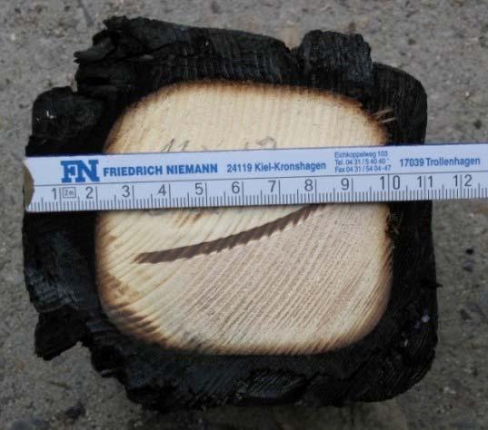
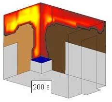
113 Basic Wood Shrinkage Theory Moisture changes cause dimensional changes perpendicular to grain Growing tree is filled with water As wood dries, it shrinks perp. to grain Image: Wood Handbook, Wood as an Engineering Material, USDA Forest Service, Forest Products Laboratory, 2010

114 Basic Wood Shrinkage Theory Shrinkage in lumber expected ACROSS the grain. Longitudinal shrinkage is negligible. Wider & Thicker NOT Taller
115 Basic Wood Shrinkage Theory

116 Zone of Movement Shrinkage occurs primarily in horizontal members Wall plates Floor/rim joists Be aware of cumulative shrinkage.
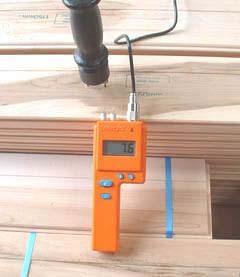
117 Pre Construction Moisture Content M i = 19% M i = 28%
118 Minimize Construction Moisture Accumulation 1. Minimize storage of material on site where rain and standing water can increase moisture content. 2. Keep unused framing material covered 3. Inspect pre built wall panels prior to installation for proper material and quality of mechanical fasteners. 4. Dry in the structure as quickly as possible. 5. Immediately remove any standing water from floor framing after rain showers.

119 In service Average EMC in July Map courtesy of US Forest Products Laboratory 132

120 In service Average EMC in January Map courtesy of US Forest Products Laboratory 133
121 Calculating Comprehensive Shrinkage Shrinkage Estimation For MC between 6 to 14% the shrinkage formula is: S S = shrinkage (in inches) D i C D i = initial dimension (in inches) T C T / C R = dimension change coefficient, tangential/radial direction M C T = for Douglas Fir Larch C T = for Hem Fir C T = for Spruce Pine Fir C T = for Southern Pine M F = final moisture content (percent) M i = initial moisture content (percent) F M i
122 Calculating Comprehensive Shrinkage Shrinkage Estimation For MC outside the range of 6 to 14% : S S = shrinkage (in inches) T Di M 30(100) S F M i 30 M D i = initial dimension (in inches) S T /S R = tangential/radial shrinkage (%) from green to oven dry M F = final moisture content (percent) M i = initial moisture content (percent) i
123 Example Shrinkage Calculation Assume: S Dry lumber Find: Shrinkage in Plates & Floor Joist Shrinkage Zone: 2x4 Upper Plate 2x12 Floor Joist 4x4 Lower Plate Total
124 Quick Shrinkage Estimation: Example Shrinkage Calculation Again assuming the initial MC (M i ) is 19 percent and the final MC (M F ) is 12 percent Our approximated shrinkage is: For Doug Fir Larch: S CD i M F M i For S P F or Southern Pine: S CD i M F M i inch inch
125 Minimizing Shrinkage Semi balloon framing incorporates floor framing hanging from top plates Eliminates tangential shrinkage in zone of movement Floor framing doesn t contribute to overall building shrinkage Non standard stud lengths and increased hardware requirements are a result.
126 Example Shrinkage Calculation Assume: S Dry lumber Find: Shrinkage in 2x4 Upper Plate & 4x4 Lower Plate Shrinkage Zone: 2x4 Upper Plate 4x4 Lower Plate 5 Total
127 Quick Shrinkage Estimation: Example Shrinkage Calculation Again assuming the initial MC (M i ) is 19 percent and the final MC (M F ) is 12 percent Our approximated shrinkage is: For Doug Fir Larch: S CD i M F M i For Southern Pine: S CD i M F M i inch inch
128 Minimizing Shrinkage Semi balloon framing incorporates floor framing hanging from top plates Eliminates tangential shrinkage in zone of movement Floor framing doesn t contribute to overall building shrinkage Non standard stud lengths and increased hardware requirements are a result.


129 Differential Movement Movement between wood frame elements and other materials that do not shrink at all shrink much less expand
130 Shrinkage & Finish Considerations Large expanses of interior and exterior drywall, paneling and siding need to be looked at specifically. Employ expansion joint and slip type detailing. Attention to interaction of structural (load bearing) and non structural elements is necessary


131 Shrinkage & MEP Considerations Fully compress wall framing by completing all dead load potential PRIOR to mechanical installations. Avoid rigid vertical piping in mechanical and plumbing systems. Flexible members allow for shrinkage between floors.


132 MEP Considerations Vertical vent stacks should be installed after completion of framing. Vent stacks require special attention and must be designed to allow for vertical movement due to shrinkage between floors.
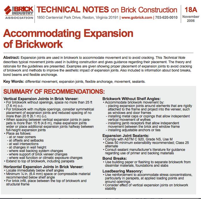
133 Brick Façade: Solution 1 Plain Unreinforced Brick h>30 Design must be in strict conformance with ACI 530 section Alt. design method (engineered) Design to section 2.2 (ASD) or (strength) unreinforced masonry Brick veneer must be self supporting and not supported off of the wood framing Joints must allow for all differential movement (lateral drift and vertical shrinkage of wood Framing Etc.). Weight of brick must not be supported by wood Framing Requires steel lintel at openings Brick goes into flexure when wall studs deflect Anchors/ties to be spaced a maximum of 32 o.c. horiz. And 18 o.c. vert. (except seismic) Veneer must be designed per ACI 530 section 2.2 as plain unreinforced masonry Wood backer studs Allows for vertical shrinkage of wood framing
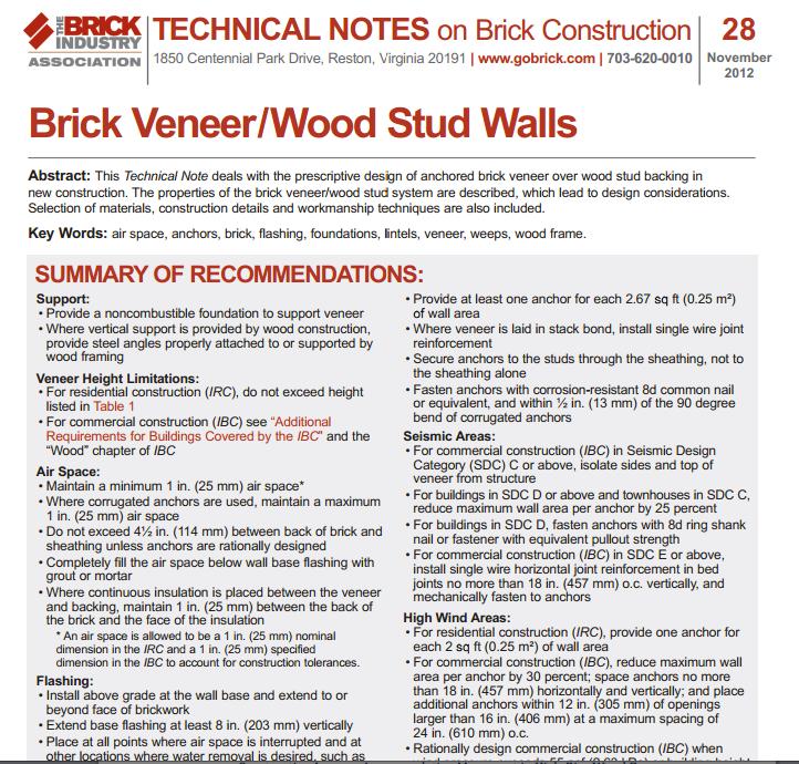
134 Brick Façade: Solution 2 Structural Reinforced Brick Brick units are similar to CMU s where vertical and horizontal reinforcing can be installed Veneer spans floor to floor without transferring loads to walls. Loads are dumped directly into floor diaphragms Steel lintels over openings are not required Intermediate anchors/ties are not required Wall spans vert. & horiz. Between spaced anchors Spaced anchors must allow for all differential movement (lateral drift, vertical shrinkage of wood Framing, etc.). Weight of brick must not be supported by wood Framing Veneer acts as complete unit, not as individual Segments. Supports self weight plus out of plane loads #3 or #4 rebar (typ.) Heavier anchors are not as prone to fire damage Wood backer studs Reinf. horizontal bond beam or lintel units over openings Reinforcement reduces expansion and cracking Anchors/ties are tied directly into floor diaphragms 4 nom. or greater
135 Façade Considerations Resources Brick Industry Association
136 Door and Window Considerations Sealant joint sized to allow shrinkage of wood frame and expansion of brick (typically ¼ to ½ per floor)


137 Shrinkage Effects on Structural Components Strap hold downs can buckle with too much accumulated movement. Anchor type holdowns should re tightened before installing finishes. Threaded rod holdowns with shrinkage compensating devices work well for 4 stories and above with stacking units.

138 Shrinkage & Deck Considerations White Paper: Multi Story Wood Frame Shrinkage Effects on Exterior Deck Drainage: A Case Study by Zeno Martin, Wood Design Focus Fall 2010


139 Shrinkage Resources
140 Outline Need for Mid rise Construction (Urban Densification) Mid rise Building Types/Configurations Maximizing Height & Area Fire Ratings & Requirements Structural Design & Detailing Considerations Shrinkage Considerations & Detailing Acoustic Requirements & Detailing Common Floor to Wall Detailing

 Evaluates how effectively an assembly blocks impact sound from passing")
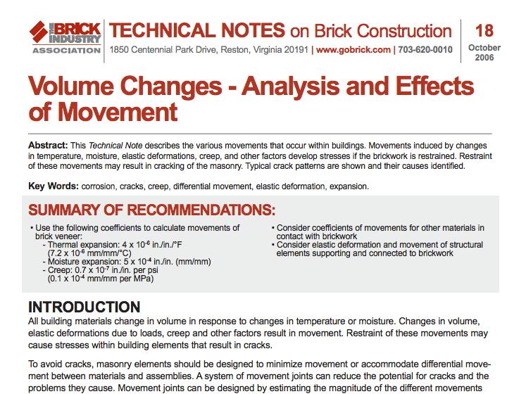
141 Building Acoustics Overview Air borne sound: Sound Transmission Class (STC) Measures how effectively an assembly isolates air borne sound and reduces the level that passes from one side to the other Structure borne sound: Impact Insulation Class (IIC) Evaluates how effectively an assembly blocks impact sound from passing through it
142 Acoustical Code Requirements IBC Section 1207: Min. STC of 50 (45 if field tested) for: All Walls, Partitions, and Floor/Ceiling Assemblies which separate adjacent dwelling units or a dwelling unit from an adjacent public area Min. IIC of 50 (45 if field tested) for: All Floor/Ceiling Assemblies which separate adjacent dwelling units or a dwelling unit from an adjacent public area
143 Acoustical Isolation Between Units Class Designation Airborne Sound Isolation (STC) Floor Ceiling Impact Isolation (IIC) Entry Level Market Rate Luxury 60 60
144 Exterior to Unit Land Use Category Exterior Day/Night Noise Levels (Ldn, dba) Single Family Multi Family Motel, Hotels Outside Use Normally Acceptable Conditionally Acceptable Normally Unacceptable Clearly Unacceptable State of California General Plan Guidelines, 1987
145 Retail to Unit Typical Floor Ceiling Detail Although common between restaurants or bars and the apartments above, the configuration shown in this detail may lead to noise complaints by apartment occupants.
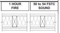
146 Rated Assemblies

147 One of Many Performance Goals University of Washington Student Housing Seattle, WA Architect: Mahlum This five building project includes a strategic combination of staggered and double stud walls to minimize sound transmission. Photo: Benjamin Benschneider

148 Acoustically Rated Assemblies Many available free online STC & IIC rated assembly charts (USG, GP, others)

149 Acoustically Rated Assemblies

150 Air Tight and Insulated Examples of ineffective and effective installation Photo Dr. Energy Saver


151 Walls Double Stud STC 63 Party Wall Photo: Econonest Architecture Inc.

152 Walls Staggered and Single Stud After double stud construction, the next best solutions are staggered and single stud. Photos: Root Graphics (l); Arch Wood Protection

153 Improvement Factor: Insulation The most cost effective acoustical improvement to a sound insulation system is the addition of batt insulation or any open cell foam system to the stud or joint cavity. Photo Dreamstime
 Metal channels found in wood")
154 Improvement Factor: Resilient Channels Acoustical puck isolator wall detail (isometric view) Metal channels found in wood framing

155 Floor Ceiling Systems
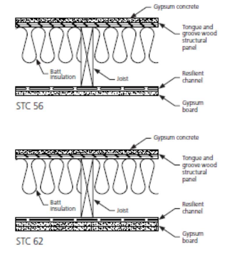
 Joist system (with 6 inches of batt insulation) Resilient channel or puck system (resilient system) Two layers of 5/8 inch type X gypsum")
156 Acoustical Detailing Effective floor ceiling option includes: Gypcrete or light weight concrete Impact isolation matt Tongue and groove subfloor (glued and screwed to the joist) Joist system (with 6 inches of batt insulation) Resilient channel or puck system (resilient system) Two layers of 5/8 inch type X gypsum board
 For clarity, batt insulation in the joist cavity is not")
157 Impact Isolation Impact Isolation Progression in Wood Frame Floors/Ceilings (Section View) For clarity, batt insulation in the joist cavity is not shown
 Avoid aligning doors on opposite sides of common hallways")
158 Additional Acoustics Best Practices Avoid creating flanking paths Isolate mechanical systems between units Seal openings in assemblies (where air flows, sound flows) Avoid aligning doors on opposite sides of common hallways
159 Outline Need for Mid rise Construction (Urban Densification) Mid rise Building Types/Configurations Maximizing Height & Area Fire Ratings & Requirements Structural Design & Detailing Considerations Shrinkage Considerations & Detailing Acoustic Requirements & Detailing Common Floor to Wall Detailing
160 Intersection of Tested Assemblies 2 Hour Wall
161 Intersection of Tested Assemblies 1 Hour Floor
162 Intersection of Tested Assemblies Many options are available for fire resistance tested floor assemblies and wall assemblies No tested intersection details exist We must understand the intent of the code, provide a rationale that meets the code s intent, and utilize available information and testing results 2 Hour Wall 1 Hour Floor 2 Hour Wall
163 Type III Exterior Walls FRT Type III and IV Construction IBC Section 602.3: Fire retardant treated wood framing complying with Section shall be permitted within exterior wall assemblies of a 2 hour rating or less What does this FRTW requirement include? Wall Framing (Studs & Plates) Yes Wall Sheathing Yes Floor sheathing? Rim Joist? Floor Joists? Everything in the plane of the wall? Or only wall framing?
164 Exterior Walls Intersecting Floors Legend FRT sheathing Floor sheathing Untreated FRT Wood Typical Platform Framing
165 Exterior Walls Intersecting Floors Legend FRT sheathing Floor sheathing Untreated FRT Wood Rim board Joist hanger Modified Platform Framing

166 Fire Resistance of Exposed Members


167 Calculated Fire Resistance of Wood For Exposed Wood Members: IBC References AWC s NDS Chapter 16 (AWC s TR 10 is a design aid to NDS Chapter 16)

168 Equations for Calculating Fire Endurance Assumptions Nominal assumed char rate = 1.5 /hr. Uses ultimate strength for design check Structurally spanning members: reduced section checked for capacity vs. demand Source: AWC s TR 10
169 Exterior Walls Intersecting Floors FRT sheathing FRT Floor sheathing Rim board Deep I joist or Bottom Chord Truss Modified Platform Framing Joist hanger
170 Exterior Walls Intersecting Floors FRT sheathing FRT Floor sheathing Joist hanger Semi Balloon Framing
171 Exterior Walls Intersecting Floors Floor sheathing (may be FRT) FRT sheathing FRT blocking Joist hanger Semi Balloon Framing w/ Add l Fire Protection
172 Exterior Walls Intersecting Floors Semi Balloon Framing w/ Add l Fire Protection 2x blocking Floor sheathing (may be FRT) FRT sheathing Top flange Joist hanger FRT blocking
173 Exterior Walls Intersecting Floors Semi Balloon Framing w/ Add l Fire Protection Floor sheathing (may be FRT) FRT sheathing Top flange Joist hanger approved to span 2 layers GWB

174 Over Gypsum Hangers
175 Exterior Walls Intersecting Floors Semi Balloon Framing w/ Ledger FRT Floor sheathing FRT sheathing FRT ledger FRT blocking Top flange Joist hanger
176 Exterior Walls Intersecting Floors Semi Balloon Framing w/ Add l Fire Protection 2x blocking Floor sheathing (may be FRT) FRT sheathing Top flange Joist hanger FRT blocking
177 Type III Construction Detail Example Platform Framing w/top Chord Bearing (2) 2x flat blocking Floor sheathing FRT sheathing Rim board FRT blocking

178 Type III Construction Detail Examples What is being enforced in jurisdictions you are working in?
179 Questions? This concludes The American Institute of Architects Continuing Education Systems Course Janelle Leafblad, PE WoodWorks Wood Products Council
180 Copyright Materials This presentation is protected by US and International Copyright laws. Reproduction, distribution, display and use of the presentation without written permission of the speaker is prohibited. The Wood Products Council 2015
Type III Fire-Resistant Design and Detailing: Exterior walls, Intersections and Balconies. For Light-Frame Wood Construction
 Type III Fire-Resistant Design and Detailing: Exterior walls, Intersections and Balconies For Light-Frame Wood Construction The Wood Products Council is a Registered Provider with The American Institute
Code Compliance for Fire Resistance-Rated Assemblies in Light-Frame Buildings
 Code Compliance for Fire Resistance-Rated Assemblies in Light-Frame Buildings Michelle Kam-Biron, PE, SE, SECB Senior Director, Education American Wood Council Copyright This presentation is protected
Learning Objectives. Copyright Materials. Timber over non-combustible Podium Structures. High Performance and Low Cost.
 Timber over non-combustible Podium Structures High Performance and Low Cost The Wood Products Council is a Registered Provider with The American Institute of Architects Continuing Education Systems The
Code Compliance for Fire Resistance-Rated Assemblies in Light-Frame Buildings. John Buddy Showalter, PE VP, Technology Transfer American Wood Council
 Code Compliance for Fire Resistance-Rated Assemblies in Light-Frame Buildings John Buddy Showalter, PE VP, Technology Transfer American Wood Council Copyright This presentation is protected by US and International
Code Compliance for Fire Resistance-Rated Assemblies in Light-Frame Buildings
 Code Compliance for Fire Resistance-Rated Assemblies in Light-Frame Buildings Michelle Kam-Biron, PE, SE, SECB Senior Director, Education American Wood Council Copyright This presentation is protected
Shaft Wall Solutions for Wood-Frame Structures. Ricky McLain, PE, SE WoodWorks Wood Products Council Boston & Waltham Workshops, December 6 & 7, 2017
 Shaft Wall Solutions for Wood-Frame Structures Ricky McLain, PE, SE WoodWorks Wood Products Council Boston & Waltham Workshops, December 6 & 7, 2017 Shaft Walls Shaft Walls Form Shaft Enclosures The purpose
Shaft Wall Solutions for Wood-Frame Structures. Ricky McLain, PE, SE WoodWorks Wood Products Council Charlotte WSF, November 2, 2017
 Shaft Wall Solutions for Wood-Frame Structures Ricky McLain, PE, SE WoodWorks Wood Products Council Charlotte WSF, November 2, 2017 Course Description It is fairly common for light wood-frame commercial
WoodWorks. Learning Objective. Presentation Overview. Fire Protection II Requirements for rated assemblies and common detailing
 WoodWorks Fire Protection II Requirements for rated assemblies and common detailing Scott Lockyear, PE Learning Objective Discuss the type of rated assembly requirements in the International Building Code.
WORKSHOP Progressive Multi- Family Design: New Opportunities for Light Frame Mid-Rise Structures
 WORKSHOP Progressive Multi- Family Design: New Opportunities for Light Frame Mid-Rise Structures February 14 16, 2017 San Diego, Long Beach, San Francisco The Wood Products Council is a Registered Provider
Copyright Materials. Learning Objectives. Design is in the Details: Solutions to Common to Mid Rise Design. Challenges
 Design is in the Details: Solutions to Common to Mid Rise Design Challenges The Wood Products Council is a Registered Provider with The American Institute of Architects Continuing Education Systems (AIA/CES).
Detailing For Wood Shrinkage
 Detailing For Wood Shrinkage Presented to: 2014 Texas Wood Solutions Fair Presented by: Doug Steimle Schaefer Disclaimer: This presentation was developed by a third party and is not funded by WoodWorks
Mid-Rise Engineering Considerations for Engineered Wood Products
 Mid-Rise Engineering Considerations for Engineered Wood Products Presented by Frank Powell, P.E. Presented by [ Presenter s Name ] Please add relevant logo here Disclaimer: This presentation was developed
Shaft Wall Solutions for Wood-Frame Structures. Ricky McLain, PE, SE WoodWorks Wood Products Council Atlanta WSF, April 25, 2018
 Shaft Wall Solutions for Wood-Frame Structures Ricky McLain, PE, SE WoodWorks Wood Products Council Atlanta WSF, April 25, 2018 Course Description It is fairly common for light wood-frame commercial and
Mid- Rise Wood Frame Fire and Life Safety Requirements. Presented by: Ethan Mar0n, P.E. February 24 & 25, 2016
 Mid- Rise Wood Frame Fire and Life Safety Requirements Presented by: Ethan Mar0n, P.E. February 24 & 25, 2016 Outline Mid- Rise Construc0on Types & Life Safety Review Exterior Walls Interior Walls Fire
Learning Objectives. Copyright Materials MULTI STORY WOOD FRAMED BUILDINGS. Prepared for Wood Products Council. Presented by James E. Churchill, P.E.
 NONSTRUCTURAL PROVISIONS FOR MULTI STORY WOOD FRAMED BUILDINGS 2010 CALIFORNIA BUILDING CODE (CBC ) Prepared for Wood Products Council WoodWorks Presented by James E. Churchill, P.E. Churchill Engineering,
Attachment A. USG Minimum Design and Construction Requirements for Wood Framed Structures
 Attachment A USG Minimum Design and Construction Requirements for Wood Framed Structures 1. General Design Criteria 1.1. Per Adopted Georgia State Minimum Standard Building Code 1.2. Minimum Live Loads
Learning Objectives. Copyright Materials NONSTRUCTURAL PROVISIONS FOR MULTI STORY WOOD FRAMED BUILDINGS 2009 WASHINGTON STATE BUILDING CODE (WSBC )
") NONSTRUCTURAL PROVISIONS FOR MULTI STORY WOOD FRAMED BUILDINGS 2009 WASHINGTON STATE BUILDING CODE (WSBC ) Prepared dfor Wood dproducts Council WoodWorks Presented by James E. Churchill, P.E. ChurchillEngineering
NONSTRUCTURAL PROVISIONS FOR MULTI STORY WOOD FRAMED BUILDINGS 2009 WASHINGTON STATE BUILDING CODE (WSBC ) Prepared dfor Wood dproducts Council WoodWorks Presented by James E. Churchill, P.E. ChurchillEngineering
Lateral Design of Mid- Rise Wood Structures
 Lateral Design of Mid- Rise Wood Structures Presented by Ricky McLain, MS, PE, SE Technical Director WoodWorks Texas Workshops December, 2016 Insert picture of me graduating college Follow the load Following
International Building Code Essentials for Wood Construction
 International Building Code Essentials for Wood Construction Dennis Richardson, P.E., C.B.O., CASp Western Regional Manager American Wood Council The Wood Products Council is a Registered Provider with
Interior FRT Wood. References of Previous Model Building Codes
 Interior FRT Wood References of Previous Model Building Codes Table of Contents SBBCI Standard Building Code 1 ICBO Uniform Building Code 3 BOCA National Building Code 5 10-SBBCI STANDARD BUILDING CODE
MEETING FIRE CODE WITH ORIENTED STRAND BOARD
 MEETING FIRE CODE WITH ORIENTED STRAND BOARD Disclaimer: This presentation was developed by a third party and is not funded by WoodWorks or the Softwood Lumber Board The Wood Products Council is a Registered
Copyright Materials. John Buddy Showalter, PE VP, Technology Transfer American Wood Council
 Program Registration Fire Design for Code Acceptance John Buddy Showalter, PE VP, Technology Transfer American Wood Council The Wood Products Council is a Registered Provider with The American Institute
Modular Wood Framing Goes Vertical
 Modular Wood Framing Goes Vertical By: Troy Bean, P.E., S.E. DCI Engineers January 2013 The Wood Products Council is a Registered Provider with. Credit(s) earned on completion of this program will be reported
Wood-Framed, Exterior Walls in Type III Construction
 Wood-Framed, Exterior Walls in Type III Construction with Engineered Wood Product Floor Framing Disclaimer: This presentation was developed by a third party and is not funded by WoodWorks or the Softwood
Code Compliant Fire- Resistance Design for Wood Construction
 Code Compliant Fire- Resistance Design for Wood Construction (BCD220-2) Paul Coats, PE, CBO Southeast Region Manager American Wood Council The American Wood Council is a Registered Provider with The American
Copyright Materials. Fire-Rated Cementitious Coated OSB in Wall and Roof Sheathing Applications
 WoodWorks National Sponsors Fire-Rated Cementitious Coated OSB in Wall and Roof Sheathing Applications www.lpcorp.com LP Building Products 2010 Slide 1 of 45 Fire-Rated Cementitious Coated OSB in Wall
Framing Methods Structural Components
 Framing Methods Structural Components Balloon Framing *Balloon framing or Eastern framing the exterior studs run from the top of the foundation to the top of the highest level. Benefits of this type of
FIRE AND SMOKE PROTECTION FEATURES
 CHAPTER 7 FIRE AND SMOKE PROTECTION FEATURES SECTION 70 GENERAL 70. Scope. The provisions of this chapter shall govern the materials, systems and assemblies used for structural fire resistance and fire-resistance-rated
Deck Frequently Asked Questions
 Deck Frequently Asked Questions Deciphering DCA6 and More (BCD307) Buddy Showalter, P.E. Vice President, Tech Transfer American Wood Council Lori Koch, P.E. Manager, Educational Outreach American Wood
HILLSBOROUGH TOWNSHIP CODE ENFORCEMENT
 HILLSBOROUGH TOWNSHIP CODE ENFORCEMENT SAMPLE GUIDE FOR RESIDENTIAL DECKS revised 7 16 Call before you dig! 1 800 272 1000 New Jersey One Call. Utility Mark Out. THIS GENERIC GUIDE IS NOT ALL INCLUSIVE
Significant Changes to AWC s Special Design Provisions for Wind and Seismic
 Significant Changes to AWC s Special Design Provisions for Wind and Seismic Michelle Kam-Biron, PE, SE, SECB Director of Education American Wood Council Copyright Materials This presentation is protected
Applying the Building Code During Design
 Applying the Building Code During Design A Step-By-Step Process AIA Learning Units The Salt Lake City CSI Chapter is a Registered Provider with The American Institute of Architects Continuing Education
Fire Resistive Design of Exposed Timber Structures
 Fire Resistive Design of Exposed Timber Structures Heavy Timber & One Hour Fire Rating Paul C. Gilham, P.E., S.E. Western Wood Structures, Inc. The Wood Products Council is a Registered Provider with The$
Administrative Changes
 Revised 11/29/06 Knox County Residential Building Codes Significant Changes From The 1995 CABO One And Two Family Dwelling Code To The 2006 International Residential Code All one and two family dwellings
Special Inspections for Wood Construction BCD710 Michelle Kam-Biron, PE, SE, SECB Senior Director, Education American Wood Council
 Special Inspections for Wood Construction BCD710 Michelle Kam-Biron, PE, SE, SECB Senior Director, Education American Wood Council Copyright Materials This presentation is protected by US and International
Lateral load basics Code acceptance of Standard. Standard Overview 2008 Wind & Seismic Standard. Wind. Wind Load Path. IBC Section 1604.
 Outline 2005/2008 Special Design Provisions for Wind & Seismic Standard Lateral load basics Code acceptance of Standard 2005/2008 Wind & Seismic Standard Overview 2008 Wind & Seismic Standard John Buddy
Interior FRT Wood. References to ICC Building Codes
 Interior FRT Wood References to ICC Building Codes Table of Contents International Building Code (IBC) 1 International Residential Code (IRC) 6 International Mechanical Code (IMC) 7 INTERNATIONAL BUILDING
2012 IBC Review of Height and Area Opportunities for Light-Frame and CLT
 2012 IBC Review of Height and Area Opportunities for Light-Frame and CLT Michelle Kam-Biron, P.E., S.E., SECB Director of Education American Wood Council Outline 2012 IBC Heights and Areas Type III, IV,
Outcomes of ICC Tall Wood Ad Hoc Committee: Proposals and Discussion
 Outcomes of ICC Tall Wood Ad Hoc Committee: Proposals and Discussion DES605 Sam Francis, C.B.O. Senior Director, National Programs American Wood Council Paul Coats, P.E., C.B.O. Southeast Regional Manager
Plan Check No. Checked by: An Appointment Is Required for Verification
 SUPPLEMENTAL CORRECTION SHEET UNREINFORCED MASONRY (URM) RETROFIT ( 2002 LABC ) Plan Check No. Checked by: Permit Appl. # An Appointment Is Required for Verification Job Address: For appt. call: APPLICATION
Cross Laminated Timber Solutions. Part 2: Addressing Common Design Challenges for Use Today
 Cross Laminated Timber Solutions Part 2: Addressing Common Design Challenges for Use Today Presented By: Jeff Peters, P.E. April 5 th 2018 Learning Objectives 1. Review answers to common questions regarding
FIGURE R502.2 FLOOR CONSTRUCTION
 CHAPTER 5 FLOORS 11 I SECTION R501 GENERAL R501.1 Application. The provisions of this chapter shall control the design and construction of the floors for all buildings including the floors of attic spaces
Following contains common verbiage found in major model building codes and has been edited for the purpose of inclusion on this CD.
 Following contains common verbiage found in major model building codes and has been edited for the purpose of inclusion on this CD. Included are selected sections of codes taken directly from: 1997 Uniform
Issue Date: April 2003 Release: I. Product Specifications
 Issue Date: April 2003 Release: I Product Specifications Forming System Components Standard System Commercial System Issue Date: April 2003 Release: I 1.1 Issue Date: April 2003 Release: I 1.2 Specification
Urban Acoustics HORBURN ASSOCIATES ACOUSTICAL, TECHNOLOGY, AND LIGHTING DESIGN. Steve(n) Thorburn, PE, LEED AP, CTS-I, CTS-D
 Thorburn, PE, LEED AP, CTS-I, CTS-D") Urban Acoustics HORBURN ASSOCIATES ACOUSTICAL, TECHNOLOGY, AND LIGHTING DESIGN Steve(n) Thorburn, PE, LEED AP, CTS-I, CTS-D SJT@TA-Inc.com Disclaimer: This presentation was developed by a third party and
Urban Acoustics HORBURN ASSOCIATES ACOUSTICAL, TECHNOLOGY, AND LIGHTING DESIGN Steve(n) Thorburn, PE, LEED AP, CTS-I, CTS-D SJT@TA-Inc.com Disclaimer: This presentation was developed by a third party and
Supplemental Plan Correction Sheet for LA Residential Code Prescriptive Design (2011 LARC)
") Supplemental Plan Correction Sheet for LA Residential Code Prescriptive Design (2011 LARC) Plan Check Submittal Date: Plan Check #: Permit App.# Job Address: Applicant: Phone: ( ) P.C. Engineer: Phone:
Supplemental Plan Correction Sheet for LA Residential Code Prescriptive Design (2011 LARC) Plan Check Submittal Date: Plan Check #: Permit App.# Job Address: Applicant: Phone: ( ) P.C. Engineer: Phone:
Supplemental Plan Check List for Unreinforced Masonry (URM) Retrofit
 Retrofit") Supplemental Plan Check List for Unreinforced Masonry (URM) Retrofit Plan Check/PCIS App #: Job Address: P.C. Engineer: Phone: (E -mail: first name.last name@ lacity.org) For instructions and other information,
Supplemental Plan Check List for Unreinforced Masonry (URM) Retrofit Plan Check/PCIS App #: Job Address: P.C. Engineer: Phone: (E -mail: first name.last name@ lacity.org) For instructions and other information,
DECK PERMIT APPLICATION
 DECK PERMIT APPLICATION APPLICANT S INFORMATION Name: Company Name: Current address: City: State: ZIP Code: Phone: Email: PROPERTY OWNER S INFORMATION Name: Property Address: Phone: E-mail: City: State:
SECTION WOOD FRAMING. A. Includes But Not Limited To 1. Furnish and install wood framing and blocking as described in Contract Documents.
 SECTION 06110 WOOD FRAMING PART 1 GENERAL 1.1 SUMMARY A. Includes But Not Limited To 1. Furnish and install wood framing and blocking as described in Contract Documents. B. Products Installed But Not Supplied
SECTION 702 DEFINITIONS
 ACTION: Final DATE: 05/6/017 :17 PM 4101:1-7-01 Fire and smoke protection features. [Comment: When a reference is made within this rule to a federal statutory provision, an industry consensus standard,
Updated references to SEI/ASCE 7 to the 2016 edition once it is available.
 Committee Input No. 8008-NFPA 5000-2015 [ Global Input ] Updated references to SEI/ASCE 7 to the 2016 edition once it is available. Submitter Information Verification Submitter Full Name: Tracy Vecchiarelli
APPENDIX A1 WIND AND SEISMIC BRACING GUIDELINE FOR ONE AND TWO FAMILY DWELLINGS AND TOWNHOUSES
 ST. LOUIS COUNTY DEPARTMENT OF PUBLIC WORKS DIVISION OF CODE ENFORCEMENT APPENDIX A1 WIND AND SEISMIC BRACING GUIDELINE FOR ONE AND TWO FAMILY DWELLINGS AND TOWNHOUSES Lateral Loads All buildings are subject
R Code and Commentary for 2012 NC Residential Code final 03/06/13
 R602.10 Code and Commentary for 2012 NC Residential Code final 03/06/13 Commentary italicized and printed in red 1. Section R602.10 -- provides charging language for two simplified bracing approaches (isolated
Two Stage Analysis Procedure: Wood on Podium Design
 Two Stage Analysis Procedure: Wood on Podium Design Part 1: Flexible Upper Portion Jared Cope, S.E. Two Stage Analysis Procedure: Wood on Podium Design 1 Two Stage Analysis: ASCE 7-10 Chapter 12 12.2.3.2
Building Codes and Ordinances ARC 227
 Building Codes and Ordinances ARC 227 Week 6 Fire Resistive Construction 03.02.10 Instructor: Rick Staub, AIA Email: staub@pointonearchitects.com Phone: 860-434-7707 Fire Resistive Construction Passive
ACCESSORY STRUCTURE Building permit information For 1 & 2-family dwellings
 ACCESSORY STRUCTURE Building permit information For 1 & 2-family dwellings Building Safety Department 400-2 nd Street South St. Cloud, MN 56301 (320) 255-7239 A building permit is required for any accessory
Code Compliant Fire- Resistance Design for Wood Construction
 Code Compliant Fire- Resistance Design for Wood Construction (BCD220-V2) Michelle Kam-Biron, PE, SE, SECB Senior Director, Education American Wood Council The Wood Products Council is a Registered Provider
Structural Design for Wind Loads: An Overview of Engineering Considerations for Wood
 Structural Design for Wind Loads: An Overview of Engineering Considerations for Wood Lori Koch, PE Manager, Educational Outreach American Wood Council Buildings Copyright Materials This presentation is
Exterior Brick Masonry Veneer Supported by Metal Plate Connected Wood Trusses (MPCWT) Overview Revised 11/17/2016
 Overview Revised 11/17/2016") Exterior Brick Masonry Veneer Supported by Metal Plate Connected Wood Trusses (MPCWT) Overview Revised 11/17/2016 SBCA has been the voice of the structural building components industry since 1983, providing
Exterior Brick Masonry Veneer Supported by Metal Plate Connected Wood Trusses (MPCWT) Overview Revised 11/17/2016 SBCA has been the voice of the structural building components industry since 1983, providing
2003 International Building Code Errata
 2003 International Building Code Errata EDITORIAL CHANGES SECOND PRINTING Page 12, CERAMIC FIBER BLANKET: Section reference now reads... 721.1.1 Page 13, CONCRETE CARBONATE AGGREGATE: now reads... See
Building Division Informational Handout
 CITY OF SAN JOSÉ, CALIFORNIA Building Division Informational Handout Conventional Light Frame Construction Design Provisions 2007 CBC Handout No. 2-21 Published: 1/1/08 Page 1 of 3 This document summarizes
Joint Evaluation Report
 0 Joint Evaluation Report ICC ES (800) 423 6587 (562) 699 0543 www.icc es.org 000 ESR 1040 Reissued 09/2018 Revised 03/2019 This report is subject to renewal 09/2019. DIVISION: 06 00 00 WOOD, PLASTICS
Table 3. Detailed Comparison of Structural Provisions of IRC 2000 and 1997 NEHRP (Continued)
") 2000 IRC 1997 NEHRP Section Provision Section Provision Comments CHAPTER 3 BUILDING PLANNING R301 DESIGN CRITERIA R301.2.2 Seismic Provisions R301.2.2.1 Determination of Seismic Design Category R301.2.2.1.1
2000 IRC 1997 NEHRP Section Provision Section Provision Comments CHAPTER 3 BUILDING PLANNING R301 DESIGN CRITERIA R301.2.2 Seismic Provisions R301.2.2.1 Determination of Seismic Design Category R301.2.2.1.1
Prescriptive Residential Wood Deck Construction Guide with Commentary DCA IRC Version (BCD 306)
") Prescriptive Residential Wood Deck Construction Guide with Commentary DCA 6-2015 IRC Version (BCD 306) Loren Ross P.E. Manager, Engineering Research American Wood Council Copyright Materials This presentation
Prescriptive Residential Wood Deck Construction Guide with Commentary DCA 6-2015 IRC Version (BCD 306) Loren Ross P.E. Manager, Engineering Research American Wood Council Copyright Materials This presentation
Joint Evaluation Report
 0 Joint Evaluation Report ICC-ES (800) 423-6587 (562) 699-0543 www.icc-es.org 000 ESR-1040 Reissued 09/2016 This report is subject to renewal 09/2018. DIVISION: 06 00 00 WOOD, PLASTICS AND COMPOSITES SECTION:
Joint Evaluation Report
 0 Joint Evaluation Report ICC-ES (800) 423-6587 (562) 699-0543 www.icc-es.org 000 ESR-1040 Reissued 09/2018 This report is subject to renewal 09/2019. DIVISION: 06 00 00 WOOD, PLASTICS AND COMPOSITES SECTION:
SECTION WOOD FRAMING. A. Includes But Not Limited To: 1. Furnish and install wood framing and blocking as described in Contract Documents.
 SECTION 06 1100 WOOD FRAMING PART 1 - GENERAL 1.1 SUMMARY A. Includes But Not Limited To: 1. Furnish and install wood framing and blocking as described in Contract Documents. B. Products Installed But
2015 IBC Exit Systems
 Objectives 2015 IBC Exit Systems Based on the 2015 International Building Code Upon completion, participants will be better able to: Determine those means of egress components that are defined as exits
WALL CONSTRUCTION CHAPTER 6
 CHAPTER 6 WALL CONSTRUCTION SECTION R601 GENERAL R601.1 Application. The provisions of this chapter shall control the design and construction of all walls and partitions for all buildings. R601.2 Requirements.
General Building Information
 Software Module s Description Page 1 General Building Information BUILDING AREA AND HEIGHT - This module designed to determine the height and area of buildings on the basis of occupancy group classification
Building for Energy Efficiency Part 2 Advanced Framing Workshop. Objectives for this presentation...
 Building for Energy Efficiency Part 2 Advanced Framing Workshop Aaron Grin Corporation www.buildingscience.com Objectives for this presentation... 1. Brief History of Advanced Framing 2. Overview 3. Benefits
TP: 89'-0" BP: 86'-6 1/4" 2'-0" Typ TP: 89'-0" BP: 86'-6 1/4" 2'-0" Typ S201 TW: 89'-0" TF: 86'-0" S201 TW: 87'-11 1/4" S201 TF: 86'-10 1/4" S201
 Resource reginc.com 0.. '-" P: '-" 0'-0" " P: '- /" 0'-" '-" '-0" '-0" 0'-0" '-0" '-" '- /" TF: '-0" TW: '-0" TF: '-0" TW: '-0" TF: '-0" TW: '- /" TF: '-" " Typ Sim. P: '-" " TF: '-0" C '- /" '-" Varies
HIGH PERFORMANCE FIRE RETARDANT TREATED WOOD PRODUCTS
 TM HIGH PERFORMANCE FIRE RETARDANT TREATED WOOD PRODUCTS Innovators of high performance fire retardant products Class A Rated Fire Retardant Treated Wood Products TM Certified and Listed with Accredited
Typical Deck. CONSTRUCTION TIP SHEET 5 Basic Decks w/ 60 psf Live Loading
 CONSTRUCTION TIP SHEET 5 Basic Decks w/ 60 psf Live Loading April 1, 2017 This Tip Sheet reflects code requirements of the 2015 International Residential Code (IRC) with Washington State Amendments which
CHAPTER 6 TYPES OF CONSTRUCTION
 CHAPTER 6 TYPES OF CONSTRUCTION SECTION 61 GENERAL 61.1 Scope. The provisions of this chapter shall control the classification of buildings as to type of construction. SECTION 62 CONSTRUCTION CLASSIFICATION
Supplemental Plan Correction Sheet for LA Residential Code Prescriptive Design (2014 LARC)
") Supplemental Plan Correction Sheet for LA Residential Code Prescriptive Design (2014 LARC) Plan Check Submittal Date: Plan Check #: Permit App.# Job Address: Applicant: Phone: ( ) Plan Check Engineer:
Supplemental Plan Correction Sheet for LA Residential Code Prescriptive Design (2014 LARC) Plan Check Submittal Date: Plan Check #: Permit App.# Job Address: Applicant: Phone: ( ) Plan Check Engineer:
Originally Issued: 11/04/2016 Revised: 11/28/2017 Valid Through: 11/30/2018
 HUBER ENGINEERED WOODS ZIP SYSTEM R-SHEATHING CSI Section: 06 12 00 Structural Panels 06 16 00 Sheathing 1.0 RECOGNITION ZIP System R-Sheathing panels, manufactured by Huber Engineered Woods, LLC, were
Wood Shear Wall Design Examples For Wind
 Wood Design Examples For Wind EARN 0.1 ICC Continuing Education Unit (CEU) and/or AIA/CES HSW 1 Learning Unit (LU) DES413-A Wood Design Examples for Wind Description: In this article, a wood frame shear
Anchor bolts ASTM F1554, Gr. 36 Wide flange beams ASTM A992, Fy = 50 ksi Misc. structural steel ASTM A36, Fy = 36 ksi
 STRUCTURAL NOTES MATERIAL STRENGTHS Structural Steel Reinforcing Steel Concrete Masonry Structural Lumber Anchor bolts ASTM F1554, Gr. 36 Wide flange beams ASTM A992, Fy = 50 ksi Misc. structural steel
VOLUNTARY - EARTHQUAKE HAZARD REDUCTION IN EXISTING HILLSIDE BUILDINGS (Division 94 Added by Ord. No. 171,258, Eff. 8/30/96.)
") DIVISION 94 VOLUNTARY - EARTHQUAKE HAZARD REDUCTION IN EXISTING HILLSIDE BUILDINGS (Division 94 Added by Ord. No. 171,258, Eff. 8/30/96.) SEC. 91.9401. PURPOSE. (Amended by Ord. No. 172,592, Eff. 6/28/99,
DIVISION 94 VOLUNTARY - EARTHQUAKE HAZARD REDUCTION IN EXISTING HILLSIDE BUILDINGS (Division 94 Added by Ord. No. 171,258, Eff. 8/30/96.) SEC. 91.9401. PURPOSE. (Amended by Ord. No. 172,592, Eff. 6/28/99,
FIRE-RESISTANCE-RATED CONSTRUCTION
 CHAPTER 7 FIRE-RESISTANCE-RATED CONSTRUCTION SECTION BC 70 GENERAL 70. Scope. The provisions of this chapter shall govern the materials and assemblies used for structural fire resistance and fire-resistance-rated
Introducing TJ Insulated Structural Framing Components
 #TJ-9009 SPECIFIER S GUIDE TJ INSULATED HEADERS, RIM BoaRD, AND CORNERS Introducing TJ Insulated Structural Framing Components Helps meet the 2011 Federal Energy Star Homes and 2009 International Energy
Strong-Drive SDWS TIMBER Screw
 Simpson Strong-Tie Fastening Systems Structural Wood-to-Wood Connections including Ledgers Designed to provide an easy-to-install, high-strength alternative to through-bolting and traditional lag screws.
Design Professionals. Acoustics
 Urban Acoustics Acoustics Room Acoustics Sound Isolation Mechanical Noise Vibration Isolation Environmental Noise Design Professionals Technology Audio Video Systems Telepresence Sound Masking/Paging Structured
Wood Solutions Fair, 2014, Toronto
 Overview of Changes to CSA O86-2014 & Structural Design Provisions for Mid-Rise in OBC Wood Solutions Fair, 2014, Toronto Jasmine Wang, Ph.D., P.Eng. Canadian Wood Council Copyright Materials This presentation
SUBJECT: NEW 2000 INTERNATIONAL RESIDENTIAL CODE (IRC) DATE:
 DATE:") IRC CODE UPDATES TO: RESIDENTIAL BUILDING CONTRACTORS FROM: GARY STABER, BUILDING OFFICIAL SUBJECT: NEW 2000 INTERNATIONAL RESIDENTIAL CODE (IRC) DATE: 6/1/2003 INTERNATIONAL RESIDENTIAL CODE (IRC) APPLICABILITY:
IRC CODE UPDATES TO: RESIDENTIAL BUILDING CONTRACTORS FROM: GARY STABER, BUILDING OFFICIAL SUBJECT: NEW 2000 INTERNATIONAL RESIDENTIAL CODE (IRC) DATE: 6/1/2003 INTERNATIONAL RESIDENTIAL CODE (IRC) APPLICABILITY:
A New Path Forward for Tall Wood Construction: Code Provisions and Design Steps
 A New Path Forward for Tall Wood Construction: Code Provisions and Design Steps Dallas Wood Design Symposium Ricky McLain, PE, SE Senior Technical Director Tall Wood WoodWorks Wood Products Council Ricky.McLain@Woodworks.org
HOOVER TREATED WOOD PRODUCTS, INC. TECHNICAL NOTE FOR ADDITIONAL INFORMATION: TEC-WOOD ( )
") HOOVER TREATED WOOD PRODUCTS, INC. TECHNICAL NOTE FOR ADDITIONAL INFORMATION: 1-800-TEC-WOOD (832-9663) Fire-Retardant-Treated Wood Framed Wall Assemblies GENERAL INFORMATION Fire-resistant construction
HOOVER TREATED WOOD PRODUCTS, INC. TECHNICAL NOTE FOR ADDITIONAL INFORMATION: 1-800-TEC-WOOD (832-9663) Fire-Retardant-Treated Wood Framed Wall Assemblies GENERAL INFORMATION Fire-resistant construction
Diaphragms 2. Design Process. Design Process. Diaphragms are the roofs and floors of the upper stories
 Diaphragms 2 Design Process Diaphragms are the roofs and floors of the upper stories They are assumed to act as a beam (usually a deep beam with substantial shear deformation) Design Process Sheathing
Mid-Rise and Beyond: The Growing Landscape for Mid-Rise and Taller Wood Buildings
 Mid-Rise and Beyond: The Growing Landscape for Mid-Rise and Taller Wood Buildings The Wood Products Council is a Registered Provider with The American Institute of Architects Continuing Education Systems
Typical Deck. CONSTRUCTION TIP SHEET 5 Basic Decks w/ 60 lb Live Loading
 CONSTRUCTION TIP SHEET 5 w/ 60 lb Live Loading April 1, 2017 This Tip Sheet reflects code requirements of the 2015 International Residential Code (IRC) with Washington State Amendments which update the
INTERNATIONAL ASSOCIATION OF PLUMBING AND MECHANICAL OFFICIALS UNIFORM EVALUATION SERVICES
 1.0 INTRODUCTION INTERNATIONAL ASSOCIATION OF PLUMBING AND MECHANICAL OFFICIALS UNIFORM EVALUATION SERVICES EVALUATION CRITERIA FOR COMPOSITE STEEL SHEET AND NONCOMBUSTIBLE SHEATHING PANELS EC 012-2016
PRODUCT: Structural Insulated Panels (SIP) DIVISION: Wood and Plastics (06) SECTION: Structural Panels ( )
 DIVISION: Wood and Plastics (06) SECTION: Structural Panels ( )") PRODUCT: Structural Insulated Panels (SIP) DIVISION: Wood and Plastics (06) SECTION: Structural Panels (06 12 16) Report Holder General Panel Corporation PO Box 279 2604 Sunset Drive Grenada, Mississippi
PRODUCT: Structural Insulated Panels (SIP) DIVISION: Wood and Plastics (06) SECTION: Structural Panels (06 12 16) Report Holder General Panel Corporation PO Box 279 2604 Sunset Drive Grenada, Mississippi
The Role of Control Layers in Building Enclosure Design
 The Role of Control Layers in Building Enclosure Design COLIN SHANE M.ENG., P.ENG. ASSOCIATE, SENIOR PROJECT MANAGER OCTOBER 13, 2016 Disclaimer: This presentation was developed by a third party and is
Details for Exterior Brick Masonry Veneer Supported by Metal Plate Connected Wood Trusses
 Details for Exterior Brick Masonry Veneer Supported by Metal Plate Connected Wood Trusses Released May 20, 2009 Updated March 9, 2011 Introduction: Wood frame structures with attached brick masonry veneer
Introducing the Design Guide for Nail-Laminated Timber Architectural Considerations SUBTITLE
 NAILED IT! Introducing the Design Guide for Nail-Laminated Timber Architectural Considerations SUBTITLE Presented by Alex Minard, Architect AIBC, MRAIC, LEED AP BD+C, CPHD Disclaimer: This presentation
&02.1. Level 3 Alterations. Level 3 Alterations shall comply with Sections & and &
 &01 GENERAL To be developed. All of the exceptions have to be coordinated. &02 SPECIAL USE AND OCCUPANCY &02.1. Level 3 Alterations. Level 3 Alterations shall comply with Sections &02.1.1 and &02.1.2.
NEWS LETTER MARCH 27, 2009
 PLANNING, BUILDING & DEVELOPMENT SERVICES DEPARTMENT 580-1 Street S.E. Medicine Hat, Alberta T1A 8E6 Telephone: 529-8374 FAX 502-8038 1 NEWS LETTER MARCH 27, 2009 GENERAL As you are probably aware there
WHITE PAPER March 7, 2013
 Liaison Committee Washington Association of Building Officials and Structural Engineers Association of Washington March 7, 2013 Abstract: This white paper establishes guidelines for specifications for
Considerations for Outof-Plane. Design
 Considerations for Outof-Plane Wall and Uplift Design WoodWorks Texas Workshops December, 2016 Overview Uplift Wall Design Wind Loads Wind loads acting on buildings are modeled as uniform surface loads.