DIVISION: CONCRETE SECTION: CONCRETE ANCHORS DIVISION: METALS SECTION: POST INSTALLED CONCRETE ANCHORS
|
|
|
- Clement Gray
- 6 years ago
- Views:
Transcription


1 0 Most Widely Accepted and Trusted ICC ES Evaluation Report ICC ES 000 (800) (562) es.org ESR 3187 Reissued 03/2018 This report is subject to renewal 03/2020. DIVISION: CONCRETE SECTION: CONCRETE ANCHORS DIVISION: METALS SECTION: POST INSTALLED CONCRETE ANCHORS REPORT HOLDER: HILTI, INC DALLAS PARKWAY, SUITE 1000 PLANO, TEXAS EVALUATION SUBJECT: HILTI HIT HY 200 ADHESIVE ANCHORS AND POST INSTALLED REINFORCING BAR CONNECTIONS IN CONCRETE Look for the trusted marks of Conformity! 2014 Recipient of Prestigious Western States Seismic Policy Council (WSSPC) Award in Excellence A Subsidiary of ICC-ES Evaluation Reports are not to be construed as representing aesthetics or any other attributes not specifically addressed, nor are they to be construed as an endorsement of the subject of the report or a recommendation for its use. There is no warranty by ICC Evaluation Service, LLC, express or implied, as to any finding or other matter in this report, or as to any product covered by the report. Copyright 2018 ICC Evaluation Service, LLC. All rights reserved.
2 ICC-ES Evaluation Report ESR-3187 Reissued March 2018 This report is subject to renewal March (800) (562) A Subsidiary of the International Code Council DIVISION: CONCRETE Section: Concrete Anchors DIVISION: METALS Section: Post-installed Concrete Anchors REPORT HOLDER: HILTI, INC DALLAS PARKWAY, SUITE 1000 PLANO, TEXAS (800) HiltiTechEng@us.hilti.com EVALUATION SUBJECT: HILTI HIT-HY 200 ADHESIVE ANCHORS AND POST INSTALLED REINFORCING BAR CONNECTIONS IN CONCRETE 1.0 EVALUATION SCOPE Compliance with the following codes: 2015, 2012, 2009 and 2006 International Building Code (IBC) 2015, 2012, 2009 and 2006 International Residential Code (IRC) 2013 Abu Dhabi International Building Code (ADIBC) The ADIBC is based on the 2009 IBC IBC code sections referenced in this report are the same sections in the ADIBC. For evaluation for compliance with codes adopted by the Los Angeles Department of Building and Safety (LADBS), see ESR-3187 LABC and LARC Supplement. Property evaluated: Structural 2.0 USES Adhesive anchors and reinforcing bars installed using the Hilti HIT-HY 200 Adhesive Anchoring System and Post- Installed Reinforcing Bar System are used to resist static, wind and earthquake (Seismic Design Categories A through F) tension and shear loads in cracked and uncracked normal-weight having a specified compressive strength, f c, of 2,500 psi to 8,500 psi (17.2 MPa to 58.6 MPa) [minimum of 24 MPa is required under ADIBC Appendix L, Section 5.1.1]. The anchor system complies with anchors as described in Section of the 2015 IBC, Section 1909 of the 2012 IBC and is an alternative to cast-in-place anchors described in Section 1908 of the 2012 IBC, and Sections 1911 and 1912 of the 2009 and 2006 IBC. The anchor systems may also be used where an engineered design is submitted in accordance with Section R of the IRC. The post-installed reinforcing bar system is an alternative to cast-in-place reinforcing bars governed by ACI 318 and IBC Chapter DESCRIPTION 3.1 General: The Hilti HIT-HY 200 Adhesive Anchoring System and Post-Installed Reinforcing Bar System are comprised of the following components: Hilti HIT-HY 200 adhesive packaged in foil packs (either Hilti HIT-HY 200-A or Hilti HIT-HY 200-R) Adhesive mixing and dispensing equipment Equipment for hole cleaning and adhesive injection The Hilti HIT-HY 200 Adhesive Anchoring System may be used with continuously threaded rod, Hilti HIT-Z(-R) anchor rods, Hilti HIS-(R)N internally threaded inserts or deformed steel reinforcing bars as depicted in Figure 1. The Hilti HIT-HY 200 Post-Installed Reinforcing Bar System may only be used with deformed steel reinforcing bars as depicted in Figure 2. The primary components of the Hilti Adhesive Anchoring and Post-Installed Reinforcing Bar Systems, including the Hilti HIT-HY 200 Adhesive, HIT-RE-M static mixing nozzle and steel anchoring elements, are shown in Figure 6 of this report. The manufacturer s printed Installation instructions (MPII), as included with each adhesive unit package, are replicated as Figure Materials: Hilti HIT-HY 200 Adhesive: Hilti HIT-HY 200 Adhesive is an injectable, two-component hybrid adhesive. The two components are separated by means of a dual-cylinder foil pack attached to a manifold. The two components combine and react when dispensed through a static mixing nozzle attached to the manifold. Hilti HIT-HY 200 is available in 11.1-ounce (330 ml) and 16.9-ounce (500 ml) foil packs. The manifold attached to each foil pack is stamped with the adhesive expiration date. The shelf life, as indicated by the expiration date, applies to an unopened foil pack stored in a dry, dark environment and in accordance with Figure 9. Hilti HIT-HY 200 Adhesive is available in two options, Hilti HIT-HY 200-A and Hilti HIT-HY 200-R. Both options are subject to the same technical data as set forth in this report. Hilti HIT-HY 200-A will have shorter working times and curing times than Hilti HIT-HY 200-R. The packaging ICC-ES Evaluation Reports are not to be construed as representing aesthetics or any other attributes not specifically addressed, nor are they to be construed as an endorsement of the subject of the report or a recommendation for its use. There is no warranty by ICC Evaluation Service, LLC, express or implied, as to any finding or other matter in this report, or as to any product covered by the report. Copyright 2018 ICC Evaluation Service, LLC. All rights reserved. Page 1 of 45
3 ESR-3187 Most Widely Accepted and Trusted Page 2 of 45 for each option employs a different color, which helps the user distinguish between the two adhesives Hole Cleaning Equipment: Standard Equipment: Standard hole cleaning equipment, comprised of steel wire brushes and air nozzles, is described in Figure 9 of this report Hilti Safe-Set System: The Hilti Safe-Set with Hilti HIT-HY 200 consists of one of the following: For the Hilti HIT-Z and HIT-Z-R anchor rods, hole cleaning is not required after drilling the hole, except if the hole is drilled with a diamond core drill bit. For the elements described in Sections through and Section 3.2.5, the Hilti TE-CD or TE-YD hollow carbide drill bit with a carbide drilling head conforming to ANSI B Used in conjunction with a Hilti vacuum with a minimum value for the maximum volumetric flow rate of 129 CFM (61 l/s), the Hilti TE-CD or TE-YD drill bit will remove the drilling dust, automatically cleaning the hole Dispensers: Hilti HIT-HY 200 must be dispensed with manual or electric dispensers provided by Hilti Anchor Elements: Hilti HIT-Z and HIT-Z-R Anchor Rods: Hilti HIT-Z and HIT-Z-R anchor rods have a conical shape on the embedded section and a threaded section above the surface. Mechanical properties for the Hilti HIT-Z and HIT-Z-R anchor rods are provided in Table 2. The rods are available in diameters as shown in Table 7 and Figure 1. Hilti HIT-Z anchor rods are produced from carbon steel and furnished with a millimeter-thick (5 m) zinc electroplated coating. Hilti HIT-Z-R anchor rods are fabricated from grade 316 stainless steel Threaded Steel Rods: Threaded steel rods must be clean, continuously threaded rods (all-thread) in diameters as described in Tables 11 and 15 and Figure 1 of this report. Steel design information for common grades of threaded rods is provided in Table 3. Carbon steel threaded rods must be furnished with a inch-thick (0.005 mm) zinc electroplated coating complying with ASTM B633 SC 1 or must be hot-dipped galvanized complying with ASTM A153, Class C or D. Stainless steel threaded rods must comply with ASTM F593 or ISO 3506 A4. Threaded steel rods must be straight and free of indentations or other defects along their length. The ends may be stamped with identifying marks and the embedded end may be blunt cut or cut on the bias to a chisel point Steel Reinforcing Bars for use in Post-Installed Anchor Applications: Steel reinforcing bars are deformed bars as described in Table 4 of this report. Tables 11, 15, and 19 and Figure 1 summarize reinforcing bar size ranges. The embedded portions of reinforcing bars must be straight, and free of mill scale, rust, mud, oil and other coatings (other than zinc) that may impair the bond with the adhesive. Reinforcing bars must not be bent after installation except as set forth in ACI (b) or ACI , as applicable, with the additional condition that the bars must be bent cold, and heating of reinforcing bars to facilitate field bending is not permitted Hilti HIS-N and HIS-RN Inserts: Hilti HIS-N and HIS-RN inserts have a profile on the external surface and are internally threaded. Mechanical properties for Hilti HIS-N and HIS-RN inserts are provided in Table 5. The inserts are available in diameters and lengths as shown in Table 22 and Figure 1. Hilti HIS-N inserts are produced from carbon steel and furnished with a millimeterthick (5 μm) zinc electroplated coating complying with ASTM B633 SC 1. The stainless steel Hilti HIS-RN inserts are fabricated from X5CrNiMo17122 K700 steel conforming to DIN Specifications for common bolt types that may be used in conjunction with Hilti HIS-N and HIS-RN inserts are provided in Table 6. Bolt grade and material type (carbon, stainless) must be matched to the insert. Strength reduction factors,, corresponding to brittle steel elements must be used for Hilti HIS-N and HIS-RN inserts Ductility: In accordance with ACI or ACI D.1, as applicable, in order for a steel element to be considered ductile, the tested elongation must be at least 14 percent and reduction of area must be at least 30 percent. Steel elements with a tested elongation of less than 14 percent or a reduction of area of less than 30 percent, or both, are considered brittle. Values for various steel materials are provided in Tables 2, 3, and 6 of this report. Where values are nonconforming or unstated, the steel must be considered brittle Steel Reinforcing Bars for Use in Post-Installed Reinforcing Bar Connections: Steel reinforcing bars used in post-installed reinforcing bar connections are deformed bars (rebar) as depicted in Figures 2 and 3. Tables 25, 26, 27, and Figure 9 summarize reinforcing bar size ranges. The embedded portions of reinforcing bars must be straight, and free of mill scale, rust and other coatings that may impair the bond with the adhesive. Reinforcing bars must not be bent after installation, except as set forth in Section (a) of ACI or Section of ACI , as applicable, with the additional condition that the bars must be bent cold, and heating of reinforcing bars to facilitate field bending is not permitted. 3.3 Concrete: Normal-weight must comply with Sections 1903 and 1905 of the IBC, as applicable. The specified compressive strength of the must be from 2,500 psi to 8,500 psi (17.2 MPa to 58.6 MPa) [minimum of 24 MPa is required under ADIBC Appendix L, Section 5.1.1]. 4.0 DESIGN AND INSTALLATION 4.1 Strength Design of Post-Installed Anchors: Refer to Table 1 for the design parameters for specific installed elements, and refer to Figure 4 and Section for a flowchart to determine the applicable design bond strength or pullout strength General: The design strength of anchors under the 2015 IBC and 2015 IRC must be determined in accordance with ACI and this report. The design strength of anchors under the 2012, 2009 and 2006 IBC, as well as the 2012, 2009 and 2006 IRC must be determined in accordance with ACI and this report. A design example according to the 2012 IBC based on ACI is given in Figure 7 of this report. Design parameters are based on ACI for use with the 2015 IBC, and ACI for use with the 2012, 2009 and 2006 IBC unless noted otherwise in Sections through of this report. The strength design of anchors must comply with ACI or ACI D.4.1 as applicable, except as required in ACI or ACI D.3.3, as applicable. Design parameters, are provided in Table 7 through Table 24. Strength reduction factors,, as given in ACI or ACI D.4.3, as applicable must be
4 ESR-3187 Most Widely Accepted and Trusted Page 3 of 45 used for load combinations calculated in accordance with Section of the IBC or ACI or ACI , as applicable. Strength reduction factors,, as given in ACI D.4.4 must be used for load combinations calculated in accordance with ACI Appendix C Static Steel Strength in Tension: The nominal static steel strength of a single anchor in tension, N sa, in accordance with ACI or ACI Section D.5.1.2, as applicable and the associated strength reduction factors,, in accordance with ACI or ACI Section D.4.3, as applicable, are provided in the tables outlined in Table 1 for the anchor element types included in this report Static Concrete Breakout Strength in Tension: The nominal breakout strength of a single anchor or group of anchors in tension, N cb or N cbg, must be calculated in accordance with ACI or ACI D.5.2, as applicable, with the following addition: The basic breakout strength of a single anchor in tension, N b, must be calculated in accordance with ACI or ACI D.5.2.2, as applicable using the values of k c,cr, and k c,uncr as described in this report. Where analysis indicates no cracking in accordance with ACI or ACI D.5.2.6, as applicable, N b must be calculated using k c,uncr and Ψ c,n = 1.0. See Table 1. For anchors in lightweight, see ACI or ACI D.3.6, as applicable. The value of f c used for calculation must be limited to 8,000 psi (55 MPa) in accordance with ACI or ACI D.3.7, as applicable. Additional information for the determination of nominal bond strength in tension is given in Section of this report Static Bond Strength/Static Pullout Strength in Tension: Static Pullout Strength In Tension: Hilti HIT-Z and HIT-Z-R Anchor Rods: The nominal static pullout strength of a single anchor in accordance with ACI and or ACI D and D.5.3.2, as applicable, in cracked and uncracked, N p,cr and N p,uncr, respectively, is given in Table 10. For all design cases Ψ c,p = 1.0. Pullout strength values are a function of the compressive strength, whether the is cracked or uncracked, the drilling method (hammer drill, including Hilti hollow drill bit, diamond core drill) and installation conditions (dry or water-saturated). The resulting characteristic pullout strength must be multiplied by the associated strength reduction factor nn as follows: DRILLING METHOD Hammerdrill (or Hilti TE- CD or TE- YD Hollow Drill Bit) or Diamond Core Bit HILTI HIT-Z AND HIT-Z-R THREADED RODS CONCRETE TYPE Uncracked Cracked PERMISSIBLE INSTALLATION CONDITIONS PULLOUT STRENGTH ASSOCIATED STRENGTH REDUCTION FACTOR Dry N p,uncr d Water saturated N p,uncr ws Dry N p,cr d Water saturated N p,cr ws Figure 4 of this report presents a pullout strength design selection flowchart. Strength reduction factors for determination of the bond strength are given in the tables referenced in Table 1 of this report Static Bond Strength in Tension: Threaded Rod, Steel Reinforcing Bars, and Hilti HIS-N and HIS- RN Inserts: The nominal static bond strength of a single adhesive anchor or group of adhesive anchors in tension, N a or N ag, must be calculated in accordance with ACI or ACI D.5.5, as applicable. Bond strength values are a function of the compressive strength, whether the is cracked or uncracked, the temperature range, and the installation conditions (dry or water-saturated ). The resulting characteristic bond strength shall be multiplied by the associated strength reduction factor nn as follows: DRILLING METHOD Hammerdrill (or Hilti TE- CD or TE- YD Hollow Drill Bit) CONCRETE TYPE Uncracked Cracked PERMISSIBLE INSTALLATION CONDITIONS BOND STRENGTH ASSOCIATED STRENGTH REDUCTION FACTOR Dry k,uncr d Water saturated k,uncr ws Dry k,cr d Water saturated k,cr ws Figure 4 of this report presents a bond strength design selection flowchart. Strength reduction factors for determination of the bond strength are outlined in Table 1 of this report. Adjustments to the bond strength may also be made for increased compressive strength as noted in the footnotes to the bond strength tables Static Steel Strength in Shear: The nominal static strength of a single anchor in shear as governed by the steel, V sa, in accordance with ACI or ACI D.6.1.2, as applicable and strength reduction factors,, in accordance with ACI or ACI D.4.3, as applicable, are given in the tables outlined in Table 1 for the anchor element types included in this report Static Concrete Breakout Strength in Shear: The nominal static breakout strength of a single anchor or group of anchors in shear, V cb or V cbg, must be calculated in accordance with ACI or ACI D.6.2, as applicable, based on information given in the tables outlined in Table 1. The basic breakout strength of a single anchor in shear, V b, must be calculated in accordance with ACI or ACI D.6.2.2, as applicable, using the values of d given in the tables as outlined in Table 1 for the corresponding anchor steel in lieu of d a (2015, 2012 and 2009 IBC) and d o (2006 IBC). In addition, h ef must be substituted for l e. In no case must l e exceed 8d. The value of f c must be limited to a maximum of 8,000 psi (55 MPa) in accordance with ACI or ACI D.3.7, as applicable Static Concrete Pryout Strength in Shear: The nominal static pryout strength of a single anchor or group of anchors in shear, V cp or V cpg, must be calculated in accordance with ACI or ACI D.6.3, as applicable Interaction of Tensile and Shear Forces: For designs that include combined tension and shear, the interaction of tension and shear loads must be calculated in accordance with ACI or ACI D.7, as applicable Minimum Member Thickness, h min, Anchor Spacing, s min and Edge Distance, c min : Hilti HIT-Z and HIT-Z-R Anchor Rods: In lieu of ACI and or ACI D.8.1 and D.8.3, as applicable, values of s min and c min described in Table 9 of this report must be observed for anchor design and installation. The minimum member thicknesses, h min, given in Table 9 of this report must be observed for anchor design and installation.
5 ESR-3187 Most Widely Accepted and Trusted Page 4 of Threaded Rod, Steel Reinforcing Bars, and Hilti HIS-N and HIS-RN Inserts: In lieu of ACI and or ACI D.8.1 and D.8.3, as applicable, values of c min and s min described in this report must be observed for anchor design and installation. Likewise, in lieu of ACI or ACI D.8.5, as applicable, the minimum member thicknesses, h min, described in this report must be observed for anchor design and installation. For adhesive anchors that will remain untorqued, ACI or ACI D.8.4, as applicable, applies. For edge distances c ai and anchor s ai, the maximum torque T max shall comply with the following requirements: REDUCED MAXIMUM INSTALLATION TORQUE T max,red FOR EDGE DISTANCES c ai < (5 x d a ) EDGE DISTANCE, c ai MINIMUM ANCHOR SPACING, s ai MAXIMUM TORQUE, T max,red 1.75 in. (45 mm) c ai 5 x d a s ai < 16 in. 0.3 x T max < 5 x d a s ai 16 in. (406 mm) 0.5 x T max Critical Edge Distance c ac and ψ cp,na : Hilti HIT-Z and HIT-Z-R Anchor Rods: In lieu of ACI or ACI D.8.6, as applicable, for the calculation of N cb and N cbg in accordance with ACI or ACI D.5.2.7, as applicable and Section of this report, the critical edge distance, c ac, must be determined as follows: i. c ac = 1.5.h ef for h/h ef 2.35 ii. c ac = 3.5.h ef for h/h ef 1.35 For definitions of h and h ef, see Figure 1. Linear interpolation is permitted to determine the ratio of c ac /h ef for values of h/h ef between 2.35 and 1.35 as illustrated in the graph above Threaded Rod, Steel Reinforcing Bars, and Hilti HIS-N and HIS-RN Inserts: The modification factor ψ cp,na, must be determined in accordance with ACI or ACI D.5.5.5, as applicable, except as noted below: For all cases where c Na /c ac <1.0, ψ cp,na determined from ACI Eq b or ACI Eq. D-27, as applicable, need not be taken less than c Na /c ac. For all other cases, ψ cp,na shall be taken as 1.0. The critical edge distance, c ac must be calculated according to Eq c for ACI or Eq. D-27a for ACI , in lieu of ACI or ACI D.8.6, as applicable. c ac =h ef k, uncr h h ef (Eq c for ACI or Eq. D-27a for ACI ) where h need not be taken as larger than 2.4; and h ef τ k,uncr is the characteristic bond strength in uncracked, h is the member thickness, and h ef is the embedment depth. τ k,uncr need not be taken as greater than: τ k,uncr = k uncr h ef f c ' Eq. (4-1) π d Design Strength in Seismic Design Categories C, D, E and F: In structures assigned to Seismic Design Category C, D, E or F under the IBC or IRC, anchors must be designed in accordance with ACI or ACI D.3.3, as applicable, except as described below: Modifications to ACI shall be applied under Section of the 2015 IBC. For the 2012 IBC, Section shall be omitted. The nominal steel shear strength, V sa, must be adjusted by V,seis as given in the tables summarized in Table 1 for the anchor element types included in this report. For tension, the nominal pullout strength N p,cr or bond strength cr must be adjusted by α N,seis. See Tables 10, 13, 14, 17, 18, 21 and 24. As an exception to ACI D : Anchors designed to resist wall out-of-plane forces with design strengths equal to or greater than the force determined in accordance with ASCE 7 Equation or shall be deemed to satisfy ACI D (d). Under ACI D (d), in lieu of requiring the anchor design tensile strength to satisfy the tensile strength requirements of ACI D.4.1.1, the anchor design tensile strength shall be calculated from ACI D The following exceptions apply to ACI D : 1. For the calculation of the in-plane shear strength of anchor bolts attaching wood sill plates of bearing or non-bearing walls of light-frame wood structures to foundations or foundation stem walls, the in-plane shear strength in accordance with ACI D.6.2 and D.6.3 need not be computed and ACI D need not apply provided all of the following are satisfied: 1.1. The allowable in-plane shear strength of the anchor is determined in accordance with AF&PA NDS Table 11E for lateral design values parallel to grain The maximum anchor nominal diameter is 5 / 8 inch (16 mm) Anchor bolts are embedded into a minimum of 7 inches (178 mm) Anchor bolts are located a minimum of 1 3 / 4 inches (45 mm) from the edge of the parallel to the length of the wood sill plate Anchor bolts are located a minimum of 15 anchor diameters from the edge of the perpendicular to the length of the wood sill plate The sill plate is 2-inch or 3-inch nominal thickness. 2. For the calculation of the in-plane shear strength of anchor bolts attaching cold-formed steel track of bearing or non-bearing walls of light-frame construction to foundations or foundation stem walls, the in-plane shear strength in accordance with ACI D.6.2 and D.6.3, need not be computed and ACI D need not apply provided all of the following are satisfied:
6 ESR-3187 Most Widely Accepted and Trusted Page 5 of The maximum anchor nominal diameter is 5 / 8 inch (16 mm) Anchors are embedded into a minimum of 7 inches (178 mm) Anchors are located a minimum of 1 3 / 4 inches (45 mm) from the edge of the parallel to the length of the track Anchors are located a minimum of 15 anchor diameters from the edge of the perpendicular to the length of the track The track is 33 to 68 mil designation thickness. Allowable in-plane shear strength of exempt anchors, parallel to the edge of shall be permitted to be determined in accordance with AISI S100 Section E In light-frame construction, bearing or nonbearing walls, shear strength of anchors less than or equal to 1 inch [25 mm] in diameter attaching a sill plate or track to foundation or foundation stem wall need not satisfy ACI D (a) through (c) when the design strength of the anchors is determined in accordance with ACI D.6.2.1(c). 4.2 Strength Design of Post-Installed Reinforcing Bars: General: The design of straight post-installed deformed reinforcing bars must be determined in accordance with ACI 318 rules for cast-in place reinforcing bar development and splices and this report. Examples of typical applications for the use of postinstalled reinforcing bars are illustrated in Figure 3 of this report. A design example in accordance with the 2012 IBC based on ACI is given in Figure 8 of this report Determination of bar development length l d : Values of l d must be determined in accordance with the ACI 318 development and splice length requirements for straight cast-in place reinforcing bars. Exceptions: 1. For uncoated and zinc-coated (galvanized) postinstalled reinforcing bars, the factor e shall be taken as 1.0. For all other cases, the requirements in ACI or ACI (b) shall apply. 2. When using alternate methods to calculate the development length (e.g., anchor theory), the applicable factors for post-installed anchors generally apply Minimum Member Thickness, h min, Minimum Concrete Cover, c c,min, Minimum Concrete Edge Distance, c b,min, Minimum Spacing, s b,min,: For postinstalled reinforcing bars, there is no limit on the minimum member thickness. In general, all requirements on cover and applicable to straight cast-in bars designed in accordance with ACI 318 shall be maintained. For post-installed reinforcing bars installed at embedment depths, h ef, larger than 20d (h ef > 20d), the minimum cover shall be as follows: REBAR SIZE d b No. 6 (16mm) No. 6 < d b No.10 (16mm < d b 32mm) MINIMUM CONCRETE COVER, c c,min 1 3 / 16 in.(30mm) 1 9 / 16 in. (40mm) The following requirements apply for minimum edge and for h ef > 20d: Required minimum edge distance for post-installed reinforcing bars (measured from the center of the bar): c b,min = d 0 /2 + c c,min Required minimum center-to-center between postinstalled bars: s b,min = d 0 + c c,min Required minimum center-to-center from existing (parallel) reinforcing: s b,min = d b /2 (existing reinforcing) + d 0 /2 + c c,min Design Strength in Seismic Design Categories C, D, E and F: In structures assigned to Seismic Category C, D, E or F under the IBC or IRC, design of straight postinstalled reinforcing bars must take into account the provisions of ACI Chapter 18 or ACI Chapter 21, as applicable. The value of f' c to be used in ACI , , and or ACI Section , , and , as applicable, calculations shall not exceed 2,500 psi for post-installed reinforcing bar applications in SDCs C, D, E, and F. 4.3 Installation: Installation parameters are illustrated in Figure 1. Installation must be in accordance with ACI and or ACI D.9.1 and D.9.2, as applicable. Anchor and post-installed reinforcing bar locations must comply with this report and the plans and specifications approved by the code official. Installation of the Hilti HIT-HY 200 Adhesive Anchor and Post-Installed Reinforcing Bar Systems must conform to the manufacturer s printed installation instructions (MPII) included in each unit package as provided in Figure 9 of this report.. The MPII contains additional requirements for combinations of drill hole depth, diameter, drill bit type, and dispensing tools. 4.4 Special Inspection: Periodic special inspection must be performed where required in accordance with Section and Table of the 2015 and 2012 IBC, Sections and of the 2009 IBC, or Section of the 2006 IBC, and this report. The special inspector must be on the jobsite initially during anchor or post-installed reinforcing bar installation to verify anchor or post-installed reinforcing bar type and dimensions, type, compressive strength, adhesive identification and expiration date, hole dimensions, hole cleaning procedures,, edge distances, thickness, anchor or post-installed reinforcing bar embedment, tightening torque and adherence to the manufacturer s printed installation instructions. The special inspector must verify the initial installations of each type and size of adhesive anchor or post-installed reinforcing bar by construction personnel on site. Subsequent installations of the same anchor or post-installed reinforcing bar type and size by the same construction personnel are permitted to be performed in the absence of the special inspector. Any change in the anchor or post-installed reinforcing bar product being installed or the personnel performing the installation requires an initial inspection. For ongoing installations over an extended period, the special inspector must make regular inspections to confirm correct handling and installation of the product. Continuous special inspection of adhesive anchors or post-installed reinforcing bar installed in horizontal or
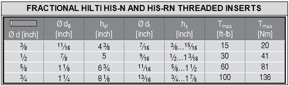
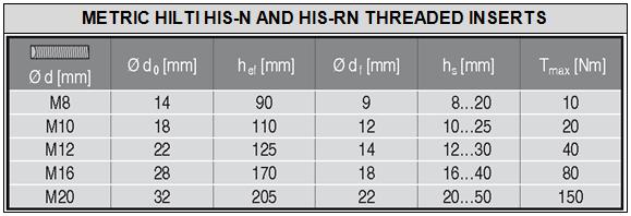
7 ESR-3187 Most Widely Accepted and Trusted Page 6 of 45 upwardly inclined orientations to resist sustained tension loads shall be performed in accordance with ACI , (h), and (c) or ACI D.9.2.4, as applicable. Under the IBC, additional requirements as set forth in Sections 1705, 1706, and 1707 must be observed, where applicable. 5.0 CONDITIONS OF USE The Hilti HIT-HY 200 Adhesive Anchor System and Post-Installed Reinforcing Bar System described in this report complies with, or is a suitable alternative to what is specified in, the codes listed in Section 1.0 of this report, subject to the following conditions: 5.1 Hilti HIT-HY 200 Adhesive anchors and post-installed reinforcing bars must be installed in accordance with the manufacturer s printed installation instructions (MPII) as included in the adhesive packaging and provided in Figure 9 of this report. 5.2 The anchors and post-installed reinforcing bars must be installed in cracked and uncracked normal-weight having a specified compressive strength f c = 2,500 psi to 8,500 psi (17.2 MPa to 58.6 MPa) [minimum of 24 MPa is required under ADIBC Appendix L, Section 5.1.1]. 5.3 The values of f c used for calculation purposes must not exceed 8,000 psi (55.1 MPa) except as noted in Sections and of this report. 5.4 The shall have attained its minimum design strength prior to installation of the adhesive anchors. 5.5 Anchors and post-installed reinforcing bars must be installed in base materials in holes predrilled in accordance with the instructions in Figure 9, using carbide-tipped masonry drill bits manufactured with the range of maximum and minimum drill-tip dimensions specified in ANSI B The Hilti HIT-Z(-R) anchor rods may be installed in holes predrilled using diamond core drill bits. 5.6 Loads applied to the anchors must be adjusted in accordance with Section of the IBC for strength design. 5.7 Hilti HIT-HY 200 adhesive anchors and post-installed reinforcing bars are recognized for use to resist shortand long-term loads, including wind and earthquake, subject to the conditions of this report. 5.8 In structures assigned to Seismic Design Category C, D, E or F under the IBC or IRC, anchor strength must be adjusted in accordance in accordance with Section of this report, and post-installed reinforcing bars must comply with section of this report. 5.9 Hilti HIT-HY 200 adhesive anchors and post-installed reinforcing bars are permitted to be installed in that is cracked or that may be expected to crack during the service life of the anchor, subject to the conditions of this report Anchor strength design values must be established in accordance with Section 4.1 of this report Post-installed reinforcing bar development and splice length is established in accordance with Section 4.2 of this report Minimum anchor and edge distance as well as minimum member thickness must comply with the values noted in this report Post-installed reinforcing bar, minimum member thickness, and cover distance must be in accordance with the provisions of ACI 318 for cast-in place bars and section of this report Prior to anchor installation, calculations and details demonstrating compliance with this report must be submitted to the code official. The calculations and details must be prepared by a registered design professional where required by the statutes of the jurisdiction in which the project is to be constructed Anchors and post-installed reinforcing bars are not permitted to support fire-resistive construction. Where not otherwise prohibited by the code, Hilti HIT-HY 200 adhesive anchors and post-installed reinforcing bars are permitted for installation in fire-resistive construction provided that at least one of the following conditions is fulfilled: Anchors and post-installed reinforcing bars are used to resist wind or seismic forces only. Anchors and post-installed reinforcing bars that support gravity load bearing structural elements are within a fire-resistive envelope or a fireresistive membrane, are protected by approved fire-resistive materials, or have been evaluated for resistance to fire exposure in accordance with recognized standards. Anchors and post-installed reinforcing bars are used to support nonstructural elements Since an ICC-ES acceptance criteria for evaluating data to determine the performance of adhesive anchors and post-installed reinforcing bars subjected to fatigue or shock loading is unavailable at this time, the use of these anchors under such conditions is beyond the scope of this report Use of zinc-plated carbon steel threaded rods or steel reinforcing bars is limited to dry, interior locations Use of hot-dipped galvanized carbon steel and stainless steel rods is permitted for exterior exposure or damp environments Steel anchoring materials in contact with preservativetreated and fire-retardant-treated wood must be of zinc-coated carbon steel or stainless steel. The minimum coating weights for zinc-coated steel must comply with ASTM A Periodic special inspection must be provided in accordance with Section 4.4 of this report. Continuous special inspection for anchors and post-installed reinforcing bars installed in horizontal or upwardly inclined orientations to resist sustained tension loads must be provided in accordance with Section 4.4 of this report Installation of anchors and post-installed reinforcing bars in horizontal or upwardly inclined orientations to resist sustained tension loads shall be performed by personnel certified by an applicable certification program in accordance with ACI or , or ACI D or D.9.2.3, as applicable Hilti HIT-HY 200 adhesive anchors and post-installed reinforcing bars may be used to resist tension and shear forces in floor, wall, and overhead installations only if installation is into with a temperature between 14 F and 104 F (-10 C and 40 C) for threaded rods, rebar, and Hilti HIS-(R)N inserts, or between 41 F and 104 F (5 C and 40 C) for Hilti HIT-
8 ESR-3187 Most Widely Accepted and Trusted Page 7 of 45 Z(-R) anchor rods. Overhead installations for hole diameters larger than 7 / 16 -inch or 10mm require the use of piston plugs (HIT-SZ, -IP) during injection to the back of the hole. 7 / 16 -inch diameter holes may be injected directly to the back of the hole with the use of extension tubing on the end of the nozzle, The anchor or post-installed reinforcing bars must be supported until fully cured (i.e., with Hilti HIT-OHW wedges, or other suitable means). Where temporary restraint devices are used, their use shall not result in impairment of the anchor shear resistance. Installations in temperatures below 32 F require the adhesive to be conditioned to a minimum temperature of 32 F Anchors and post-installed reinforcing bars when installed at temperatures below 40 F shall not be used for applications where the temperature can rise from 40 F or less to 80 F or higher within a 12-hour period. Such applications may include but are not limited to anchorage of building facade systems and other applications subject to direct sun exposure Hilti HIT-HY 200-A and Hilti HIT-HY 200-R adhesives are manufactured by Hilti GmbH, Kaufering, Germany, under a quality control program with inspections by ICC-ES Hilti HIT-Z and HIT-Z-R rods are manufactured by Hilti AG, Schaan, Liechtenstein, under a quality-control program with inspections by ICC-ES Hilti HIS-N and HIS-RN inserts are manufactured by Hilti (China) Ltd., Guangdong, China, under a qualitycontrol program with inspections by ICC-ES. 6.0 EVIDENCE SUBMITTED Data in accordance with the ICC-ES Acceptance Criteria for Post-installed Adhesive Anchors in Concrete (AC308), dated October 2017, which incorporates requirements in ACI , and Table 3.8 for evaluating post-installed reinforcing bars. 7.0 IDENTIFICATION 7.1 Hilti HIT-HY 200-A and Hilti HIT-HY 200-R adhesive is identified by packaging labeled with the manufacturer s name (Hilti Corp.) and address, product name, lot number, expiration date, and evaluation report number (ESR-3187). 7.2 Hilti HIT-Z and HIT-Z-R rods are identified by packaging labeled with the manufacturer's name (Hilti Corp.) and address, anchor name, and evaluation report number (ESR-3187). 7.3 Hilti HIS-N and HIS-RN inserts are identified by packaging labeled with the manufacturer's name (Hilti Corp.) and address, anchor name and size, and evaluation report number (ESR-3187). 7.4 Threaded rods, nuts, washers, bolts, cap screws, and deformed reinforcing bars are standard elements and must conform to applicable national or international specifications.
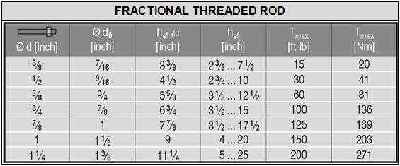
 in (mm) in (mm) In (mm) in (mm) HIT-Z(-R) 3 / 8 x3 3 / 8 3 3 / 8 (85) 2 1 / 4 (57) 3 / 8 (6) 13 / 16 (21) 5 / 16 (8) HIT-Z(-R) 3 / 8 '' x 4 3 / 8 '' 4 3 / 8 (111) 2 1 / 4 (57)")
 2 1 / 2 (63) HIT-Z(-R) 1 / 2 '' x 7 3 / 4 '' 7 3 / 4 (197) 2 1 / 2 (63) HIT-Z(-R) 5 / 8 '' x 6'' 6 (152) 3 5 / 8 (92) HIT-Z(-R) 5 / 8 '' x 8'' 8 (203) 3 5 / 8 (92) 5 / 16 (8) 1")
 4 5 / 16 (109) 7 / 16 (11) 1 15 / 16 (49) 1 1 / 8 (28) 7 / 16 (11) 3 15 / 16 (100) 3 1 / 8 (79) HIT-Z(-R) 5 / 8 '' x 9 1 / 2 '' 9 1 / 2 (241) 3 5 / 8 (92) 1 15 / 16 (49) 3 15 / 16 (100) 3 1 / 8")
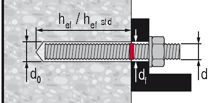
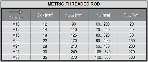
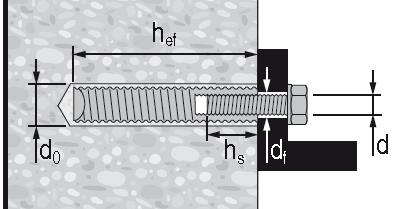
9 ESR-3187 Most Widely Accepted and Trusted Page 8 of 45 HILTI HIT-Z AND HIT-Z-R ANCHOR ROD h Name and Size l Anchor Length l helix Helix Length Smooth Shank Length Total Thread Length Usable Thread Length in (mm) in (mm) in (mm) In (mm) in (mm) HIT-Z(-R) 3 / 8 x3 3 / / 8 (85) 2 1 / 4 (57) 3 / 8 (6) 13 / 16 (21) 5 / 16 (8) HIT-Z(-R) 3 / 8 '' x 4 3 / 8 '' 4 3 / 8 (111) 2 1 / 4 (57) HIT-Z(-R) 3 / 8 '' x 5 1 / 8 '' 5 1 / 8 (130) 2 1 / 4 (57) HIT-Z(-R) 3 / 8 '' x 6 3 / 8 '' 6 3 / 8 (162) 2 1 / 4 (57) HIT-Z(-R) 1 / 2 '' x 4 1 / 2 '' 4 1 / 2 (114) 2 1 / 2 (63) HIT-Z(-R) 1 / 2 '' x 6 1 / 2 '' 6 1 / 2 (165) 2 1 / 2 (63) HIT-Z(-R) 1 / 2 '' x 7 3 / 4 '' 7 3 / 4 (197) 2 1 / 2 (63) HIT-Z(-R) 5 / 8 '' x 6'' 6 (152) 3 5 / 8 (92) HIT-Z(-R) 5 / 8 '' x 8'' 8 (203) 3 5 / 8 (92) 5 / 16 (8) 1 13 / 16 (46) 1 5 / 16 (33) 5 / 16 (8) 2 9 / 16 (65) 2 1 / 16 (52) 5 / 16 (8) 3 13 / 16 (97) 3 5 / 16 (84) 5 / 16 (8) 1 11 / 16 (43) 1 (26) 5 / 16 (8) 3 11 / 16 (94) 3 1 / 16 (77) 5 / 16 (8) 4 15 / 16 (126) 4 5 / 16 (109) 7 / 16 (11) 1 15 / 16 (49) 1 1 / 8 (28) 7 / 16 (11) 3 15 / 16 (100) 3 1 / 8 (79) HIT-Z(-R) 5 / 8 '' x 9 1 / 2 '' 9 1 / 2 (241) 3 5 / 8 (92) 1 15 / 16 (49) 3 15 / 16 (100) 3 1 / 8 (79) HIT-Z(-R) ¾ x 6½ 6½ (165) 4 (102) HIT-Z(-R) 3 / 4 '' x 8 1 / 2 '' 8 1 / 2 (216) 4 (102) 5 / 16 (8) 2 (51) 1 (26) 7 / 16 (12) 4 (102) 3 1 / 16 (77) HIT-Z(-R) 3 / 4 '' x 9 3 / 4 '' 9 3 / 4 (248) 4 (102) 1 11 / 16 (44) 4 (102) 3 1 / 16 (77) HIT-Z(-R) M10x / 4 (95) 2 3 / 8 (60) 5 / 16 (8) 1 1 / 8 (27) 9 / 16 (14) HIT-Z(-R) M10x / 2 (115) 2 3 / 8 (60) HIT-Z(-R) M10x / 16 (135) 2 3 / 8 (60) HIT-Z(-R) M10x / 16 (160) 2 3 / 8 (60) 5 / 16 (8) 1 7 / 8 (47) 1 5 / 16 (34) 5 / 16 (8) 2 5 / 8 (67) 2 1 / 8 (54) 5 / 16 (8) 3 5 / 8 (92) 3 1 / 8 (79) HIT-Z(-R) M12x / 8 (105) 2 3 / 8 (60) 5 / 16 (8) 1 1 / 2 (37) 13 / 16 (21) HIT-Z(-R) M12x / 2 (140) 2 3 / 8 (60) HIT-Z(-R) M12x / 8 (155) 2 3 / 8 (60) HIT-Z(-R) M12x / 4 (196) 2 3 / 8 (60) HIT-Z(-R) M16x / 8 (155) 3 11 / 16 (93) HIT-Z(-R) M16x / 8 (175) 3 11 / 16 (93) HIT-Z(-R) M16x / 16 (205) 3 11 / 16 (93) 5 / 16 (8) 2 7 / 8 (72) 2 3 / 16 (56) 5 / 16 (8) 3 3 / 8 (87) 2 13 / 16 (71) 5 / 16 (8) 5 (128) 4 7 / 16 (112) 7 / 16 (11) 2 (51) 1 3 / 16 (30) 7 / 16 (11) 2 13 / 16 (71) 1 15 / 16 (50) 7 / 16 (11) 4 (101) 3 1 / 8 (80) HIT-Z(-R) M16x / 16 (240) 3 11 / 16 (93) 1 1 / 4 (32) 4 1 / 2 (115) 3 11 / 16 (94) HIT-Z(-R) M20x / 2 (215) 3 15 / 16 (100) 1 / 2 (13) 4 (102) 3 1 / 16 (78) HIT-Z(-R) M20x / 16 (250) 3 15 / 16 (100) 1 7 / 8 (48) 4 (102) 3 1 / 16 (78) FIGURE 1 INSTALLATION PARAMETERS FOR POST-INSTALLED ADHESIVE ANCHORS


10 ESR-3187 Most Widely Accepted and Trusted Page 9 of 45 DEFORMED REINFORCMENT THREADED ROD h h HILTI HIS-N AND HIS-RN THREADED INSERTS h FIGURE 1 INSTALLATION PARAMETERS FOR POST INSTALLED ADHESIVE ANCHORS (Continued)


 DEVELOPMENT OF SHEAR DOWELS")
11 ESR-3187 Most Widely Accepted and Trusted Page 10 of 45 FIGURE 2 INSTALLATION PARAMATERS FOR POST-INSTALLED REINFORCING BARS (A) (B) (C) FIGURE 3 APPLICATION EXAMPLES FOR POST-INSTALLED REINFORCING BARS: (A) TENSION LAP SPLICE WITH EXISTING FLEXURAL REINFORCEMENT; (B) TENSION DEVELOPMENT OF COLUMN DOWELS; (C) DEVELOPMENT OF SHEAR DOWELS FOR NEWLY THICKENED SHEAR WALL
12 ESR-3187 Most Widely Accepted and Trusted Page 11 of 45 Design Table TABLE 1 DESIGN TABLE INDEX Fractional Metric Table Page Table Page Hilti HIT-Z and HIT-Z-R Anchor Rod Steel Strength - N sa, V sa Concrete Breakout - N cb, N cbg, V cb, V cbg, V cp, V cpg Pullout Strength N p Standard Threaded Rod Steel Strength - N sa, V sa Concrete Breakout - N cb, N cbg, V cb, V cbg, V cp, V cpg Bond Strength - N a, N ag Hilti HIS-N and HIS-RN Internally Threaded Insert Steel Strength - N sa, V sa Concrete Breakout - N cb, N cbg, V cb, V cbg, V cp, V cpg Bond Strength - N a, N ag Design Table Fractional EU Metric Canadian Table Page Table Page Table Page Steel Reinforcing Bars Steel Strength - N sa, V sa 11A Concrete Breakout - N cb, N cbg, V cb, V cbg, V cp, V cpg Bond Strength - N a, N ag Determination of development length for post-installed reinforcing bar connections FIGURE 4 FLOWCHART FOR THE ESTABLISHMENT OF DESIGN BOND OR PULLOUT STRENGTH FOR POST-INSTALLED ADHESIVE ANCHORS
13 ESR-3187 Most Widely Accepted and Trusted Page 12 of 45 TABLE 2 SPECIFICATIONS AND PHYSICAL PROPERTIES OF FRACTIONAL AND METRIC HIT-Z AND HIT-Z RODS HIT-Z AND HIT-Z-R ROD SPECIFICATION Minimum specified ultimate strength, f uta Minimum specified yield strength 0.2 percent offset, f ya f uta /f ya Elongation, min. percent Reduction of Area, min. percent Specification for nuts 2 CARBON STEEL STAINLESS STEEL 3 / 8 -in. to 5 / 8 -in. and M10 to M12 - AISI / 4 -in. - AISI 1038 or 18MnV5 M16 - AISI 1038 M20 - AISI 1038 or 18MnV5 3 / 8 -in. to 3 / 4 -in. and M10 to M12 Grade 316 DIN-EN X5CrNiMo AT M16 Grade 316 DIN-EN X5CrNiMo AT M20 Grade 316 DIN-EN X5CrNiMo AT psi 94,200 75,300 (MPa) (650) (520) psi 88,400 71,000 (MPa) (610) (490) psi 86,200 69,600 (MPa) (595) (480) psi 94,200 75,300 (MPa) (650) (520) psi 88,400 71,000 (MPa) (610) (490) psi 86,200 69,600 (MPa) (595) (480) ASTM A563 Grade A ASTM F594 Type Steel properties are minimum values and maximum values will vary due to the cold forming of the rod. 2 Nuts of other grades and styles having specified proof load stresses greater than the specified grade and style are also suitable. Nuts must have specified proof load stresses equal to or greater than the minimum tensile strength of the specified threaded rod. THREADED ROD SPECIFICATION CARBON STEEL STAINLESS STEEL ASTM A193 2 Grade B7 2 1 / 2 in. ( 64 mm) ASTM F568M 3 Class 5.8 M5 ( 1 / 4 in.) to M24 (1 in.) (equivalent to ISO 898-1) TABLE 3 SPECIFICATIONS AND PHYSICAL PROPERTIES OF COMMON CARBON AND STAINLESS STEEL THREADED ROD MATERIALS 1 Minimum specified ultimate strength, f uta Minimum specified yield strength 0.2 percent offset, f ya psi 125, ,000 (MPa) (862) (724) f uta /f ya Elongation, min. percent 7 Reduction of Area, min. percent Specification for nuts ASTM A563 Grade DH psi 72,500 58, ASTM A563 Grade DH 9 (MPa) (500) (400) DIN 934 (8-A2K) psi 58,000 36,000 ASTM F1554, Grade 36 7 (MPa) (400) (248) ASTM F1554, Grade 55 7 psi 75,000 55,000 (MPa) (517) (379) ASTM F1554, Grade psi 125, ,000 (MPa) (862) (724) ISO Class 5.8 ISO Class 8.8 ASTM F593 5 CW1 (316) 1 / 4 -in. to 5 / 8 -in. ASTM F593 5 CW2 (316) 3 / 4 -in. to 1 1 / 2 -in. ASTM A193 Grade 8(M), Class ¼-in. ISO A4-70 M8 M24 ISO A4-50 M27 M30 MPa (psi) (72,500) (58,000) MPa (psi) (116,000) (92,800) psi 100,000 65,000 (MPa) (689) (448) psi 85,000 45,000 (MPa) (586) (310) psi 75,000 30,000 (MPa) (517) (207) MPa (psi) (101,500) (65,250) MPa (psi) (72,500) (30,450) ASTM A194 or ASTM A ASTM A194 or ASTM A ASTM A194 or ASTM A DIN 934 Grade DIN 934 Grade ASTM F ASTM F ASTM F ISO ISO Hilti HIT-HY 200 adhesive may be used in conjunction with all grades of continuously threaded carbon or stainless steel rod (all-thread) that comply with the code reference standards and that have thread characteristics comparable with ANSI B1.1 UNC Coarse Thread Series or ANSI B1.13M M Profile Metric Thread Series. Values for threaded rod types and associated nuts supplied by Hilti are provided here. 2 Standard Specification for Alloy-Steel and Stainless Steel Bolting Materials for High-Temperature Service 3 Standard Specification for Carbon and Alloy Steel Externally Threaded Metric Fasteners 4 Mechanical properties of fasteners made of carbon steel and alloy steel Part 1: Bolts, screws and studs 5 Standard Steel Specification for Stainless Steel Bolts, Hex Cap Screws, and Studs 6 Mechanical properties of corrosion-resistant stainless steel fasteners Part 1: Bolts, screws and studs 7 Based on 2-in. (50 mm) gauge length except for A 193, which are based on a gauge length of 4d and ISO 898, which is based on 5d. 8 Nuts of other grades and styles having specified proof load stresses greater than the specified grade and style are also suitable. Nuts must have specified proof load stresses equal to or greater than the minimum tensile strength of the specified threaded rod. 9 Nuts for fractional rods.
14 ESR-3187 Most Widely Accepted and Trusted Page 13 of 45 TABLE 4 SPECIFICATIONS AND PHYSICAL PROPERTIES OF COMMON STEEL REINFORCING BARS REINFORCING BAR SPECIFICATION Minimum specified ultimate strength, f uta Minimum specified yield strength, f ya ASTM A615 1 Gr. 60 ASTM A615 1 Gr. 40 ASTM A706 2 Gr. 60 DIN BSt 500 CAN/CSA-G Gr Standard Specification for Deformed and Plain Carbon Steel Bars for Concrete Reinforcement 2 Standard Specification for Low Alloy Steel Deformed and Plain Bars for Concrete Reinforcement 3 Reinforcing steel; reinforcing steel bars; dimensions and masses 4 Billet-Steel Bars for Concrete Reinforcement psi 90,000 60,000 (MPa) (620) (414) psi 60,000 40,000 (MPa) (414) (276) psi 80,000 60,000 (MPa) (550) (414) MPa (psi) (79,750) (72,500) MPa (psi) (78,300) (58,000) TABLE 5 SPECIFICATIONS AND PHYSICAL PROPERTIES OF FRACTIONAL AND METRIC HIS-N AND HIS-RN INSERTS HILTI HIS-N AND HIS-RN INSERTS Minimum specified ultimate Minimum specified yield strength, f strength, f ya uta Carbon Steel DIN EN SMnPb30+c or DIN SMnPb28K 3 / 8 -in. and M8 to M10 Carbon Steel DIN EN SMnPb30+c or DIN SMnPb28K 1 / 2 to 3 / 4 -in. and M12 to M20 Stainless Steel EN X5CrNiMo psi 71,050 59,450 (MPa) (490) (410) psi 66,700 54,375 (MPa) (460) (375) psi 101,500 50,750 (MPa) (700) (350) BOLT, CAP SCREW OR STUD SPECIFICATION SAE J429 3 Grade 5 ASTM A / 2 to 1-in. ASTM A193 5 Grade B8M (AISI 316) for use with HIS-RN ASTM A193 5 Grade B8T (AISI 321) for use with HIS-RN TABLE 6 SPECIFICATIONS AND PHYSICAL PROPERTIES OF COMMON BOLTS, CAP SCREWS AND STUDS FOR USE WITH HIS-N AND HIS-RN INSERTS 1,2 Minimum specified ultimate strength f uta Minimum specified yield strength 0.2 percent offset f ya psi 120,000 92,000 (MPa) (828) (634) psi 120,000 92,000 (MPa) (828) (634) psi 110,000 95,000 (MPa) (759) (655) psi 125, ,000 (MPa) (862) (690) f uta /f ya Elongation, min. Reduction of Area, min. Specification for nuts SAE J Minimum Grade 5 bolts, cap screws or studs must be used with carbon steel HIS inserts. 2 Only stainless steel bolts, cap screws or studs must be used with HIS-RN inserts. 3 Mechanical and Material Requirements for Externally Threaded Fasteners 4 Standard Specification for Structural Bolts, Steel, Heat Treated, 120/105 ksi Minimum Tensile Strength 5 Standard Specification for Alloy-Steel and Stainless Steel Bolting Materials for High-Temperature Service 6 Nuts must have specified minimum proof load stress equal to or greater than the specified minimum full-size tensile strength of the specified stud. 7 Nuts for stainless steel studs must be of the same alloy group as the specified bolt, cap screw, or stud. A563 C, C3, D, DH, DH3 Heavy Hex ASTM F594 7 Alloy Group 1, 2 or 3 ASTM F594 7 Alloy Group 1, 2 or 3
15 ESR-3187 Most Widely Accepted and Trusted Page 14 of 45 Fractional and Metric HIT-Z and HIT-Z-R Anchor Rod Steel Strength TABLE 7 STEEL DESIGN INFORMATION FOR FRACTIONAL AND METRIC HIT-Z AND HIT-Z-R ANCHOR RODS DESIGN INFORMATION Symbol Units Nominal Rod Dia. (in.) Fractional Nominal Rod Dia. (mm) Metric Units 3 / / 8 1 / 2 5 / 8 Rod O.D. Rod effective crosssectional area CARBON STEEL STAINLESS STEEL Nominal strength as governed by steel strength 1 Reduction for seismic shear d A se N sa V sa in mm (mm) (9.5) (12.7) (15.9) (19.1) (in.) (0.39) (0.47) (0.63) (0.79) in mm (mm 2 ) (50) (92) (146) (216) (in. 2 ) (0.090) (0.131) (0.243) (0.380) lb 7,306 13,377 21,306 31,472 kn (kn) (32.5) (59.5) (94.8) (140.0) (lb) (8,475) (12,318) (21,529) (32,770) lb 3,215 5,886 9,375 13,848 kn (kn) (14.3) (26.2) (41.7) (61.6) (lb) (3,729) (5,420) (9,476) (14,421) V,seis Strength reduction factor for tension Strength reduction factor for shear Nominal strength as governed by steel strength 1 Reduction for seismic shear N sa V sa lb 7,306 13,377 21,306 31,472 kn (kn) (32.5) (59.5) (94.8) (140.0) (lb) (8,475) (12,318) (21,529) (32,770) lb 4,384 8,026 12,783 18,883 kn (kn) (19.5) (35.7) (56.9) (84.0) (lb) (5,085) (7,391) (12,922) (19,666) V,seis Strength reduction factor for tension Strength reduction factor for shear For SI: 1 inch 25.4 mm, 1 lbf = N, 1 psi = MPa. For pound-inch units: 1 mm = inches, 1 N = lbf, 1 MPa = psi 1 Steel properties are minimum values and maximum values will vary due to the cold forming of the rod. 2 For use with the load combinations of ACI or ACI , as set forth in ACI or ACI D.4.3.
16 ESR-3187 Most Widely Accepted and Trusted Page 15 of 45 Fractional and Metric HIT-Z and HIT-Z-R Anchor Rod Concrete Breakout Strength Carbide Bit or Hilti Hollow Carbide Bit or Diamond Core Bit TABLE 8 CONCRETE BREAKOUT DESIGN INFORMATION FOR U.S. CUSTOMARY UNIT HIT-Z AND HIT-Z-R ANCHOR ROD IN HOLES DRILLED WITH A HAMMER DRILL AND CARBIDE BIT (OR HILTI HOLLOW CARBIDE DRILL BIT) OR A CORE DRILL 1 DESIGN INFORMATION Symbol Units Nominal Rod Dia. (in.) Fractional Nominal Rod Dia. (mm) Metric Units 3 / / 8 1 / 2 5 / 8 Effectiveness factor for cracked Effectiveness factor for uncracked Minimum embedment depth 3 Maximum embedment depth 3 in-lb 17 SI 7.1 k c,cr (SI) (7.1) (in-lb) (17) in-lb 24 SI 10 k c,uncr (SI) (10) (in-lb) (24) h ef,min h ef,max in. 2 3 / / / 4 4 mm (mm) (60) (70) (95) (102) (in.) (2.4) (2.8) (3.8) (3.9) in. 4 1 / / / 2 mm (mm) (114) (152) (190) (216) (in.) (4.7) (5.7) (7.6) (8.7) Min. anchor s min - See Section of this report. Pre-calculated combinations of anchor and edge distance are given in Min. edge distance c min - Table 9 of this report. - Minimum thickness Hole condition 1 3 Minimum thickness Hole condition 2 3 Critical edge distance splitting (for uncracked ) h min,1 h min,2 - See Section of this report. Pre-calculated combinations of anchor and edge distance are given in Table 9 of this report. in. h ef / 4 h ef + 4 mm h ef + 60 h ef (mm) (h ef + 57) (h ef + 102) (in.) (h ef + 2.4) (h ef + 3.9) in. h ef / 4 > 4 h ef / 4 mm h ef + 30 > 100 h ef + 45 (mm) (h ef + 32 > 100) (h ef + 45) (in.) (h ef > 3.9) (h ef + 1.8) c ac - See Section of this report - See Section of this report Strength reduction factor for tension, failure modes, Condition B 2 Strength reduction factor for shear, failure modes, Condition B 2 For SI: 1 inch 25.4 mm, 1 lbf = N, 1 psi = MPa. For pound-inch units: 1 mm = inches, 1 N = lbf, 1 MPa = psi 1 Additional setting information is described in Figure 9, Manufacturers Printed Installation Instructions (MPII). 2 Values provided for post-installed anchors under Condition B without supplementary reinforcement as defined in ACI or ACI D Borehole condition is described in Figure 5 below. Hole Condition 1 non-cleaned hole Hole Condition 2 drilling dust is completely removed FIGURE 5 BOREHOLE SETTING CONDITIONS FOR HILTI HIT-Z AND HIT-Z-R ANCHOR RODS
17 ESR-3187 Most Widely Accepted and Trusted Page 16 of 45 UNCRACKED CONCRETE CRACKED CONCRETE TABLE 9 PRE-CALCULATED EDGE DISTANCE AND SPACING COMBINATIONS FOR HILTI HIT-Z AND HIT-Z-R RODS DESIGN INFORMATION Symbol Units Nominal Rod Diameter (in.) Fractional Rod O.D. d in. / 8 (mm) (9.5) Effective embedment h ef in. 2 3 / / / 2 (mm) (60) (86) (114) Drilled hole condition or or or 2 Minimum thickness h in / / / / / / / / 8 (mm) (102) (117) (146) (117) (143) (162) (146) (171) (187) Minimum edge and c min,1 (mm) (79) (70) (57) (70) (57) (51) (57) (48) (48) Case 1 2 in. 9 1 / s / / / / / / / / 2 min,1 (mm) (232) (197) (156) (197) (165) (143) (156) (137) (114) in. 3 1 / / / / / / / / 8 in. 5 5 / Minimum edge and c / / / / / / / / 4 min,2 (mm) (143) (121) (95) (121) (98) (83) (95) (79) (70) Case 2 2 in. 1 7 / s / / / / / / / / 8 min,2 (mm) (48) (48) (48) (48) (48) (48) (48) (48) (48) in. 2 1 / Minimum edge and c / / / / / / / / 8 min,1 (mm) (54) (48) (48) (48) (48) (48) (48) (48) (48) Case 1 2 in. 6 3 / s / / / / / / / 8 min,1 (mm) (162) (140) (108) (140) (89) (67) (83) (51) (48) in. 3 5 / Minimum edge and c / / / / / / / 8 min,2 (mm) (92) (79) (60) (79) (64) (54) (60) (51) (48) Case 2 2 UNCRACKED CONCRETE CRACKED CONCRETE s min,2 in. 1 7 / / / / / / / / / 8 (mm) (48) (48) (48) (48) (48) (48) (48) (48) (48) DESIGN INFORMATION Symbol Units Nominal Rod Diameter (in.) Fractional Rod O.D. d in. / 2 (mm) (12.7) Effective embedment h ef in. 2-3 / / 2 6 (mm) (70) (114) (152) Drilled hole condition or or or 2 Minimum thickness h in / / / / / / / 4 (mm) (102) (127) (181) (146) (171) (210) (184) (210) (248) Minimum edge and c min,1 (mm) (130) (105) (73) (92) (76) (64) (73) (64) (64) Case 1 2 in / s / / / / / / 4 5 min,1 (mm) (378) (302) (219) (260) (229) (184) (206) (184) (127) in. 5 1 / / / / / / / / 2 in. 9 1 / Minimum edge and c / / / / / / / / 8 min,2 (mm) (235) (184) (124) (159) (133) (105) (121) (105) (86) Case 2 2 in. 2 1 / s / / / / / / / / 2 min,2 (mm) (64) (64) (64) (64) (64) (64) (64) (64) (64) in. 3 5 / Minimum edge and c / / / / / / / 2 min,1 (mm) (92) (76) (64) (67) (64) (64) (64) (64) (64) Case 1 2 in / s / / / / / / / 2 min,1 (mm) (276) (216) (152) (187) (140) (79) (114) (79) (64) in. 6 1 / Minimum edge and c / / / / / / / 2 min,2 (mm) (165) (127) (83) (108) (89) (70) (83) (70) (64) Case 2 2 UNCRACKED CONCRETE CRACKED CONCRETE s min,2 in. 2 1 / / / / / / / / / 2 (mm) (64) (64) (64) (64) (64) (64) (64) (64) (64) DESIGN INFORMATION Symbol Units Nominal Rod Diameter (in.) Fractional Rod O.D. d in. / 8 (mm) (15.9) Effective embedment h ef in. 3 3 / / / 2 (mm) (95) (143) (191) Drilled hole condition or or or 2 Minimum thickness h in. 5 1 / / / / / / / / / 4 (mm) (140) (197) (238) (187) (244) (267) (235) (292) (311) Minimum edge and c min,1 (mm) (159) (114) (95) (117) (92) (83) (95) (79) (79) Case 1 2 in / s / / / / / / / / 8 min,1 (mm) (467) (327) (270) (352) (264) (248) (276) (213) (187) in. 6 1 / / / / / / / / / 8 in / Minimum edge and c / / / / / / / / 8 min,2 (mm) (289) (197) (159) (210) (156) (140) (162) (124) (117) Case 2 2 in. 3 1 / s / / / / / / / / 8 min,2 (mm) (79) (79) (79) (79) (79) (79) (79) (79) (79) in. 4 5 / Minimum edge and c / / / / / / / / 8 min,1 (mm) (117) (86) (79) (89) (79) (79) (79) (79) (79) Case 1 2 in / s / / / / / / / / 8 min,1 (mm) (352) (241) (222) (257) (165) (137) (181) (98) (79) in. 8 1 / Minimum edge and c / / / / / / / / 8 min,2 (mm) (210) (140) (111) (149) (108) (98) (114) (86) (79) Case 2 2 s min,2 in. 3 1 / / / / / / / / / 8 (mm) (79) (79) (79) (79) (79) (79) (79) (79) (79) For SI: 1 inch 25.4 mm 1 See Figure 5 for description of drilled hole condition. 2 Linear interpolation is permitted to establish an edge distance and combination between case 1 and case 2. Linear interpolation for a specific edge distance c, where c min,1 < c < c min,2, will determine the permissible, s, as follows: s min, 1 smin,2 s s min, 2 c cmin,2 cmin, 1 cmin,2
18 ESR-3187 Most Widely Accepted and Trusted Page 17 of 45 TABLE 9 PRE-CALCULATED EDGE DISTANCE AND SPACING COMBINATIONS FOR HILTI HIT-Z AND HIT-Z-R RODS (Continued) DESIGN INFORMATION Symbol Units Nominal Rod Diameter (in.) Fractional Rod O.D. d in. / 4 (mm) (19.1) Effective embedment h ef in / / 2 (mm) (102) (171) (216) Drilled hole condition or or or 2 Minimum thickness h in. 5 3 / / / / / / / / 2 (mm) (146) (203) (292) (216) (273) (333) (260) (318) (368) Minimum edge and c min,1 (mm) (248) (178) (127) (168) (133) (108) (140) (114) (102) Case 1 2 in / s / / / / / 4 11 min,1 (mm) (730) (524) (356) (492) (387) (321) (406) (337) (279) in. 9 3 / / / / / / 2 4 in / Minimum edge and c / / / / / / / / 2 min,2 (mm) (460) (321) (216) (302) (232) (184) (244) (197) (165) Case 2 2 in. 3 3 / s / / / / / / / / 4 min,2 (mm) (95) (95) (95) (95) (95) (95) (95) (95) (95) in. 7 1 / Minimum edge and c / / / / / / 4 min,1 (mm) (184) (133) (105) (127) (102) (95) (105) (95) (95) Case 1 2 in / s / / / / / / / 2 min,1 (mm) (552) (394) (311) (368) (289) (229) (308) (222) (165) in / Minimum edge and c / / / / / / 2 min,2 (mm) (337) (235) (152) (219) (168) (130) (178) (140) (114) Case 2 2 UNCRACKED CONCRETE CRACKED CONCRETE UNCRACKED CONCRETE CRACKED CONCRETE s min,2 in. 3 3 / / / / / / / / / 4 (mm) (95) (95) (95) (95) (95) (95) (95) (95) (95) DESIGN INFORMATION Symbol Units Nominal Rod Diameter (mm) Metric Rod O.D. d mm 10 (in.) (0.39) Effective embedment h ef mm (in.) (2.36) (3.54) (4.72) Drilled hole condition or or or 2 Minimum thickness h mm (in.) (3.94) (4.72) (6.14) (4.72) (5.91) (6.91) (5.91) (7.09) (7.74) mm Minimum edge and c min,1 (in.) (3.90) (3.27) (2.52) (3.27) (2.60) (2.24) (2.60) (2.17) (2.01) Case 1 2 mm s min,1 (in.) (11.61) (9.61) (7.36) (9.61) (7.76) (6.54) (7.76) (6.46) (5.83) mm Minimum edge and c min,2 (in.) (7.13) (5.83) (4.33) (5.83) (4.53) (3.78) (4.53) (3.66) (3.31) Case 2 2 mm s min,2 (in.) (1.97) (1.97) (1.97) (1.97) (1.97) (1.97) (1.97) (1.97) (1.97) mm Minimum edge and c min,1 (in.) (2.80) (2.32) (2.05) (2.32) (1.97) (1.97) (1.97) (1.97) (1.97) Case 1 2 mm s min,1 (in.) (8.23) (6.85) (5.91) (6.85) (5.16) (4.17) (5.16) (3.31) (2.60) mm Minimum edge and c min,2 (in.) (4.88) (3.98) (2.91) (3.98) (3.03) (2.52) (3.03) (2.44) (2.17) Case 2 2 UNCRACKED CONCRETE CRACKED CONCRETE s min,2 mm (in.) (1.97) (1.97) (1.97) (1.97) (1.97) (1.97) (1.97) (1.97) (1.97) DESIGN INFORMATION Symbol Units Nominal Rod Diameter (mm) Metric Rod O.D. d mm 12 (in.) (0.47) Effective embedment h ef mm (in.) (2.76) (4.25) (5.67) Drilled hole condition or or or 2 Minimum thickness h mm (in.) (3.94) (5.12) (7.24) (5.43) (6.61) (8.21) (6.85) (8.03) (9.21) mm Minimum edge and c min,1 (in.) (5.47) (4.21) (2.99) (3.98) (3.27) (2.64) (3.15) (2.68) (2.36) Case 1 2 mm s min,1 (in.) (16.38) (12.60) (8.86) (11.81) (9.72) (7.83) (9.41) (8.03) (6.93) mm Minimum edge and c min,2 (in.) (10.16) (7.64) (5.16) (7.13) (5.75) (4.49) (5.51) (4.57) (3.90) Case 2 2 mm s min,2 (in.) (2.36) (2.36) (2.36) (2.36) (2.36) (2.36) (2.36) (2.36) (2.36) mm Minimum edge and c min,1 (in.) (3.98) (3.07) (2.44) (2.91) (2.40) (2.36) (2.36) (2.36) (2.36) Case 1 2 mm s min,1 (in.) (11.93) (9.13) (7.32) (8.54) (7.01) (4.96) (6.61) (4.61) (3.11) mm Minimum edge and c min,2 (in.) (7.17) (5.35) (3.54) (5.00) (3.98) (3.03) (3.78) (3.11) (2.64) Case 2 2 s min,2 mm (in.) (2.36) (2.36) (2.36) (2.36) (2.36) (2.36) (2.36) (2.36) (2.36) For SI: 1 inch 25.4 mm 1 See Figure 5 for description of drilled hole condition. 2 Linear interpolation is permitted to establish an edge distance and combination between case 1 and case 2. Linear interpolation for a specific edge distance c, where c min,1 < c < c min,2, will determine the permissible, s, as follows: s min, 1 smin,2 s s min, 2 c cmin,2 cmin, 1 cmin,2
19 ESR-3187 Most Widely Accepted and Trusted Page 18 of 45 TABLE 9 PRE-CALCULATED EDGE DISTANCE AND SPACING COMBINATIONS FOR HILTI HIT-Z AND HIT-Z-R RODS (Continued) DESIGN INFORMATION Symbol Units Nominal Rod Diameter (mm) Metric Rod O.D. d mm 16 (in.) (0.63) Effective embedment h ef mm (in.) (3.78) (5.67) (7.56) Drilled hole condition or or or 2 Minimum thickness h mm (in.) (5.55) (7.72) (9.33) (7.44) (9.61) (10.57) (9.33) (11.50) (12.28) mm Minimum edge and c min,1 (in.) (6.22) (4.49) (3.70) (4.65) (3.62) (3.27) (3.70) (3.15) (3.15) Case 1 2 mm s min,1 (in.) (18.62) (13.35) (11.06) (13.86) (10.67) (9.76) (11.06) (8.54) (7.40) mm Minimum edge and c min,2 (in.) (11.38) (7.91) (6.34) (8.23) (6.14) (5.47) (6.34) (4.96) (4.57) Case 2 2 mm s min,2 (in.) (3.15) (3.15) (3.15) (3.15) (3.15) (3.15) (3.15) (3.15) (3.15) mm Minimum edge and c min,1 (in.) (4.57) (3.27) (3.15) (3.39) (3.15) (3.15) (3.15) (3.15) (3.15) Case 1 2 mm s min,1 (in.) (13.50) (9.76) (8.31) (10.16) (6.30) (5.08) (6.73) (3.70) (3.19) mm Minimum edge and c min,2 (in.) (8.03) (5.47) (4.37) (5.75) (4.21) (3.74) (4.37) (3.35) (3.15) Case 2 2 UNCRACKED CONCRETE CRACKED CONCRETE UNCRACKED CONCRETE CRACKED CONCRETE s min,2 mm (in.) (3.15) (3.15) (3.15) (3.15) (3.15) (3.15) (3.15) (3.15) (3.15) DESIGN INFORMATION Symbol Units Nominal Rod Diameter (mm) Metric Rod O.D. d mm 20 (in.) (0.79) Effective embedment h ef mm (in.) (3.94) (7.09) (8.66) Drilled hole condition or or or 2 Minimum thickness h mm (in.) (5.71) (7.87) (11.08) (8.86) (11.02) (13.17) (10.43) (12.60) (14.57) mm Minimum edge and c min,1 (in.) (9.25) (6.69) (4.76) (5.98) (4.80) (4.06) (5.08) (4.21) (3.94) Case 1 2 mm s min,1 (in.) (27.64) (20.12) (14.25) (17.76) (14.29) (11.85) (15.08) (12.48) (9.92) mm Minimum edge and c min,2 (in.) (17.17) (12.09) (8.23) (10.59) (8.27) (6.69) (8.82) (7.09) (5.94) Case 2 2 mm s min,2 (in.) (3.94) (3.94) (3.94) (3.94) (3.94) (3.94) (3.94) (3.94) (3.94) mm Minimum edge and c min,1 (in.) (6.93) (5.04) (4.02) (4.49) (3.94) (3.94) (3.94) (3.94) (3.94) Case 1 2 mm s min,1 (in.) (20.71) (14.96) (11.73) (13.27) (9.69) (6.42) (10.91) (7.01) (4.45) mm Minimum edge and c min,2 (in.) (12.52) (8.74) (5.83) (7.60) (5.87) (4.69) (6.26) (4.96) (4.13) Case 2 2 For SI: 1 inch 25.4 mm s min,2 mm (in.) (3.94) (3.94) (3.94) (3.94) (3.94) (3.94) (3.94) (3.94) (3.94) 1 See Figure 5 for description of drilled hole condition. 2 Linear interpolation is permitted to establish an edge distance and combination between case 1 and case 2. Linear interpolation for a specific edge distance c, where c min,1 < c < c min,2, will determine the permissible, s, as follows: s s min2 + s min1- s min2 c min1 - c min2 c- c min2
20 ESR-3187 Most Widely Accepted and Trusted Page 19 of 45 Fractional and Metric HIT-Z and HIT-Z-R Anchor Rod Pullout Strength Carbide Bit or Hilti Hollow Carbide Bit or Diamond Core Bit TABLE 10 PULLOUT STRENGTH DESIGN INFORMATION FOR FRACTIONAL AND METRIC HILTI HIT-Z AND HIT-Z-R RODS IN HOLES DRILLED WITH A HAMMER DRILL AND CARBIDE BIT (OR HILTI HOLLOW CARBIDE DRILL BIT) OR A CORE DRILL 1 DESIGN INFORMATION Symbol Units Nominal Rod Dia. (in.) Fractional Nominal Rod Dia. (mm) Metric Units 3 / / 8 1 / 2 5 / 8 Minimum embedment depth Maximum embedment depth h ef,min h ef,max in. 2 3 / / / 4 4 mm (mm) (60) (70) (95) (102) (in.) (2.4) (2.8) (3.8) (3.9) in. 4 1 / / / 2 mm (mm) (114) (152) (190) (216) (in.) (4.7) (5.7) (7.6) (8.7) Temperature range A 2 Pullout strength in cracked Pullout strength in uncracked N p,cr N p,uncr lb 7,952 10,936 21,391 27,930 kn (kn) (35.4) (48.6) (95.1) (124.2) (lb) (8,790) (9,847) (22,032) (28,754) lb 7,952 11,719 21,391 28,460 kn (kn) (35.4) (52.1) (95.1) (126.6) (lb) (8,790) (10,545) (22,028) (29,293) Temperature range B 2 Pullout strength in cracked Pullout strength in uncracked N p,cr N p,uncr lb 7,952 10,936 21,391 27,930 kn (kn) (35.4) (48.6) (95.1) (124.2) (lb) (8,790) (9,847) (22,032) (28,754) lb 7,952 11,719 21,391 28,460 kn (kn) (35.4) (52.1) (95.1) (126.6) (lb) (8,790) (10,545) (22,028) (29,293) Temperature range C 2 Pullout strength in cracked Pullout strength in uncracked N p,cr N p,uncr lb 7,182 9,877 19,321 25,227 kn (kn) (31.9) (43.9) (85.9) (112.2) (lb) (7,936) (8,880) (19,897) (25,967) lb 7,182 10,585 19,321 25,705 kn (kn) (31.9) (47.1) (85.9) (114.3) (lb) (7,936) (9,532) (19,897) (26,461) Permissible installation conditions Dry, water saturated Anchor Category d, ws Reduction for seismic tension N,seis For SI: 1 inch 25.4 mm, 1 lbf = N, 1 psi = MPa. For pound-inch units: 1 mm = inches, 1 N = lbf, 1 MPa = psi 1 Temperature range A: Maximum short term temperature = 130 F (55 C), Maximum long term temperature = 110 F (43 C). Temperature range B: Maximum short term temperature = 176 F (80 C), Maximum long term temperature = 110 F (43 C). Temperature range C: Maximum short term temperature = 248 F (120 C), Maximum long term temperature = 162 F (72 C). Short term elevated temperatures are those that occur over brief intervals, e.g., as a result of diurnal cycling. Long term temperatures are roughly constant over significant periods of time.
21 ESR-3187 Most Widely Accepted and Trusted Page 20 of 45 Fractional Threaded Rod Steel Strength ISO Class 5.8 TABLE 11 STEEL DESIGN INFORMATION FOR FRACTIONAL THREADED ROD DESIGN INFORMATION Symbol Units Nominal rod diameter (in.) 1 / 8 / 2 / 8 / 4 / / 4 Rod O.D. d in (mm) (9.5) (12.7) (15.9) (19.1) (22.2) (25.4) (31.8) Rod effective cross-sectional area A se in (mm 2 ) (50) (92) (146) (216) (298) (391) (625) lb 5,620 10,290 16,385 24,250 33,470 43,910 70,260 N sa Nominal strength as governed by steel (kn) (25.0) (45.8) (72.9) (107.9) (148.9) (195.3) (312.5) strength ASTM A193 B7 ASTM F1554 Gr. 36 ASTM F1554 Gr. 55 ASTM F1554 Gr. 105 ASTM F593, CW Stainless ASTM A193, Gr. 8(M), Class 1 Stainless V sa lb 3,370 6,175 9,830 14,550 20,085 26,345 42,155 (kn) (15.0) (27.5) (43.7) (64.7) (89.3) (117.2) (187.5) Reduction for seismic shear V,seis Strength reduction factor for tension Strength reduction factor for shear lb 9,685 17,735 28,250 41,810 57,710 75, ,135 Nominal strength as governed by steel strength N sa V sa (kn) (43.1) (78.9) (125.7) (186.0) (256.7) (336.8) (538.8) lb 5,810 10,640 16,950 25,085 34,625 45,425 72,680 (kn) (25.9) (47.3) (75.4) (111.6) (154.0) (202.1) (323.3) Reduction for seismic shear V,seis Strength reduction factor for tension Strength reduction factor for shear lb - 8,230 13,110 19,400 26,780 35,130 56,210 Nominal strength as governed by steel strength N sa V sa (kn) - (36.6) (58.3) (86.3) (119.1) (156.3) (250.0) lb - 4,940 7,865 11,640 16,070 21,080 33,725 (kn) - (22.0) (35.0) (51.8) (71.5) (93.8) (150.0) Reduction factor, seismic shear v,seis Strength reduction factor for tension Strength reduction factor for shear lb - 10,645 16,950 25,090 34,630 45,430 72,685 Nominal strength as governed by steel strength N sa V sa (kn) - (47.4) (75.4) (111.6) (154.0) (202.1) (323.3) lb - 6,385 10,170 15,055 20,780 27,260 43,610 (kn) - (28.4) (45.2) (67.0) (92.4) (121.3) (194.0) Reduction factor, seismic shear v,seis Strength reduction factor for tension Strength reduction factor for shear lb - 17,740 28,250 41,815 57,715 75, ,135 Nominal strength as governed by steel strength N sa V sa (kn) - (78.9) (125.7) (186.0) (256.7) (336.8) (538.8) lb - 10,645 16,950 25,090 34,630 45,430 72,680 (kn) - (47.4) (75.4) (111.6) (154.0) (202.1) (323.3) Reduction factor, seismic shear v,seis Strength reduction factor for tension Strength reduction factor for shear lb 7,750 14,190 22,600 28,435 39,245 51,485 - N Nominal strength as governed by steel sa (kn) (34.5) (63.1) (100.5) (126.5) (174.6) (229.0) - strength lb 4,650 8,515 13,560 17,060 23,545 30,890 - V sa (kn) (20.7) (37.9) (60.3) (75.9) (104.7) (137.4) - Reduction factor, seismic shear v,seis Strength reduction factor for tension Strength reduction factor for shear lb - 55,240 N sa Nominal strength as governed by steel (kn) - (245.7) strength lb - 33,145 V sa (kn) - (147.4) Reduction factor, seismic shear v,seis Strength reduction factor for tension Strength reduction factor for shear For SI: 1 inch = 25.4 mm, 1 lbf = N. For pound-inch units: 1 mm = inches, 1 N = lbf 1 Values provided for common rod material types are based on specified strengths and calculated in accordance with ACI Eq. ( ) and Eq ( b) or ACI Eq. (D-2) and Eq. (D-29). Nuts and washers must be appropriate for the rod. 2 For use with the load combinations of IBC Section , ACI or ACI , as set forth in ACI or ACI D.4.3. If the load combinations of ACI Appendix C are used, the appropriate value of must be determined in accordance with ACI D.4.4. Values correspond to a brittle steel element. 3 For use with the load combinations of IBC Section , ACI or ACI , as set forth in ACI or ACI D.4.3. If the load combinations of ACI Appendix C are used, the appropriate value of must be determined in accordance with ACI D.4.4. Values correspond to a ductile steel element.
22 ESR-3187 Most Widely Accepted and Trusted Page 21 of 45 Fractional Reinforcing Bars Steel Strength ASTM A615 Grade 40 TABLE 11A STEEL DESIGN INFORMATION FOR FRACTIONAL REINFORCING BARS DESIGN INFORMATION Symbol Units Nominal Reinforcing bar size (Rebar) #3 #4 #5 #6 #7 #8 #9 #10 Nominal bar diameter d in. / 8 / 2 / 8 / 4 / / / 4 (mm) (9.5) (12.7) (15.9) (19.1) (22.2) (25.4) (28.6) (31.8) Bar effective cross-sectional area A se in (mm 2 ) (71) (129) (200) (284) (387) (510) (645) (819) lb 6,600 12,000 18,600 26,400 36,000 47,400 60,000 76,200 N sa Nominal strength as governed by steel (kn) (29.4) (53.4) (82.7) (117.4) (160.1) (210.9) (266.9) (339.0) strength ASTM A615 Grade 60 ASTM A706 Grade 60 V sa lb 3,960 7,200 11,160 15,840 21,600 28,440 36,000 45,720 (kn) (17.6) (32.0) (49.6) (70.5) (96.1) (126.5) (160.1) (203.4) Reduction for seismic shear V,seis Strength reduction factor for tension Strength reduction factor for shear lb 9,900 18,000 27,900 39,600 54,000 71,100 90, ,300 Nominal strength as governed by steel strength N sa V sa (kn) (44.0) (80.1) (124.1) (176.2) (240.2) (316.3) (400.4) (508.5) lb 5,940 10,800 16,740 23,760 32,400 42,660 54,000 68,580 (kn) (26.4) (48.0) (74.5) (105.7) (144.1) (189.8) (240.2) (305.1) Reduction for seismic shear V,seis Strength reduction factor for tension Strength reduction factor for shear lb 8,800 16,000 24,800 35,200 48,000 63,200 80, ,600 Nominal strength as governed by steel strength N sa V sa (kn) (39.1) (71.2) (110.3) (156.6) (213.5) (281.1) (355.9) (452.0) lb 5,280 9,600 14,880 21,120 28,800 37,920 48,000 60,960 (kn) (23.5) (42.7) (66.2) (94.0) (128.1) (168.7) (213.5) (271.2) Reduction for seismic shear V,seis 0.70 Strength reduction factor for tension Strength reduction factor for shear For SI: 1 inch = 25.4 mm, 1 lbf = N. For pound-inch units: 1 mm = inches, 1 N = lbf 1 Values provided for common rod material types are based on specified strengths and calculated in accordance with ACI Eq. ( ) and Eq ( b) or ACI Eq. (D-2) and Eq. (D-29). Nuts and washers must be appropriate for the rod. 2 For use with the load combinations of IBC Section , ACI or ACI , as set forth in ACI or ACI D.4.3. If the load combinations of ACI Appendix C are used, the appropriate value of must be determined in accordance with ACI D.4.4. Values correspond to a brittle steel element. 3 For use with the load combinations of IBC Section , ACI or ACI , as set forth in ACI or ACI D.4.3. If the load combinations of ACI Appendix C are used, the appropriate value of must be determined in accordance with ACI D.4.4. Values correspond to a ductile steel element.
23 ESR-3187 Most Widely Accepted and Trusted Page 22 of 45 Fractional Threaded Rod and Reinforcing Bars Concrete Breakout Strength Carbide Bit or Hilti Hollow Carbide Bit TABLE 12 CONCRETE BREAKOUT DESIGN INFORMATION FOR FRACTIONAL THREADED ROD AND REINFORCING BARS IN HOLES DRILLED WITH A HAMMER DRILL AND CARBIDE BIT (OR HILTI HOLLOW CARBIDE DRILL BIT) 1 DESIGN INFORMATION Symbol Units Effectiveness factor for cracked Effectiveness factor for uncracked 3 / 8 or #3 1 / 2 or #4 Nominal rod diameter (in.) / Reinforcing bar size 5 / 8 or #5 3 / 4 or #6 k c,cr in-lb 17 (SI) (7.1) k c,uncr in-lb 24 (SI) (10) 7 / 8 or #7 Minimum Embedment h ef,min in. 2 3 / / / / / / 2 5 (mm) (60) (70) (79) (89) (89) (102) (114) (127) Maximum Embedment Min. anchor 3 Min. edge distance (Threaded rods) h ef,max s min c min in. 7 1 / / / / or #8 #9 1 1 / 4 or #10 (mm) (191) (254) (318) (381) (445) (508) (572) (635) in. 1 7 / / / / / / / 4 (mm) (48) (64) (79) (95) (111) (127) (143) (159) in. 1¾ 1¾ 2 (3) 2 1 (3) / 8 2¼ (3) 2¾ (3) 3 1 (3) / 8 n/a (mm) (45) (45) (50) (3) (55) (3) (60) (3) (70) (3) (80) (3) Min. edge distance (Reinforcing bars) 3 c min - 5d; or see Section of this report for design with reduced minimum edge distances Minimum thickness h min in. h ef / 4 (mm) (h ef + 30) (4) h ef + 2d 0 Critical edge distance splitting c ac - See Section of this report. (for uncracked ) Strength reduction factor for tension, failure modes, Condition B 2 Strength reduction factor for shear, failure modes, Condition B For SI: 1 inch 25.4 mm, 1 lbf = N, 1 psi = MPa. For pound-inch units: 1 mm = inches, 1 N = lbf, 1 MPa = psi 1 Additional setting information is described in Figure 9, Manufacturers Printed Installation Instructions (MPII). 2 Values provided for post-installed anchors under Condition B without supplementary reinforcement as defined in ACI or ACI D For installations with 1 3 / 4 -inch edge distance, refer to Section for and maximum torque requirements. 4 d 0 = hole diameter.
24 ESR-3187 Most Widely Accepted and Trusted Page 23 of 45 Fractional Reinforcing Bars Bond Strength Carbide Bit or Hilti Hollow Carbide Bit TABLE 13 BOND STRENGTH DESIGN INFORMATION FOR FRACTIONAL REINFORCING BARS IN HOLES DRILLED WITH A HAMMER DRILL AND CARBIDE BIT (OR HILTI HOLLOW CARBIDE DRILL BIT) 1 DESIGN INFORMATION Symbol Units Minimum Embedment Maximum Embedment Temperature range A 2 Temperature range B 2 Temperature range C 2 strength in cracked strength in uncracked strength in cracked strength in uncracked strength in cracked strength in uncracked h ef,min Nominal reinforcing bar size #3 #4 #5 #6 #7 #8 #9 #10 in. 2 3 / / / / / / 2 5 (mm) (60) (70) (79) (89) (89) (102) (114) (127) in. 7 1 / / / / 2 25 (mm) (191) (254) (318) (381) (445) (508) (572) (635) k,cr (MPa) (7.4) (7.4) (7.5) (7.5) (5.7) (5.8) (5.9) (5.9) psi 1,080 1,080 1,090 1, h ef,max k,uncr (MPa) (10.8) (10.8) (10.8) (10.8) (10.8) (10.8) (10.8) (10.8) psi 1,560 1,560 1,560 1,560 1,560 1,560 1,560 1,560 k,cr (MPa) (6.8) (6.9) (6.9) (6.9) (5.3) (5.3) (5.4) (5.4) psi k,uncr (MPa) (9.9) (9.9) (9.9) (9.9) (9.9) (9.9) (9.9) (9.9) psi 1,435 1,435 1,435 1,435 1,435 1,435 1,435 1,435 k,cr k,uncr psi (MPa) (5.8) (5.9) (5.9) (5.9) (4.5) (4.6) (4.6) (4.6) psi 1,230 1,230 1,230 1,230 1,230 1,230 1,230 1,230 (MPa) (8.5) (8.5) (8.5) (8.5) (8.5) (8.5) (8.5) (8.5) Permissible installation conditions Dry Water saturated Anchor Category - 1 d Anchor Category - 2 ws Reduction for seismic tension N,seis For SI: 1 inch 25.4 mm, 1 lbf = N, 1 psi = MPa. For pound-inch units: 1 mm = inches, 1 N = lbf, 1 MPa = psi 1 Bond strength values correspond to compressive strength f c = 2,500 psi (17.2 MPa). For compressive strength, f c, between 2,500 psi (17.2 MPa) and 8,000 psi (55.2 MPa) [minimum of 24 MPa is required under ADIBC Appendix L, Section 5.1.1], the tabulated characteristic bond strength may be increased by a factor of (f c / 2,500) 0.1 [For SI: (f' c / 17.2) 0.1 ]. See Section of this report for bond strength determination. 2 Temperature range A: Maximum short term temperature = 130 F (55 C), Maximum long term temperature = 110 F (43 C). Temperature range B: Maximum short term temperature = 176 F (80 C), Maximum long term temperature = 110 F (43 C). Temperature range C: Maximum short term temperature = 248 F (120 C), Maximum long term temperature = 162 F (72 C). Short term elevated temperatures are those that occur over brief intervals, e.g., as a result of diurnal cycling. Long term temperatures are roughly constant over significant periods of time.
25 ESR-3187 Most Widely Accepted and Trusted Page 24 of 45 Fractional Threaded Rod Bond Strength Carbide Bit or Hilti Hollow Carbide Bit TABLE 14 BOND STRENGTH DESIGN INFORMATION FOR FRACTIONAL THREADED ROD IN HOLES DRILLED WITH A HAMMER DRILL AND CARBIDE BIT (OR HILTI HOLLOW CARBIDE DRILL BIT) 1 DESIGN INFORMATION Symbol Units 3 / 8 1 / 2 Nominal rod diameter (in.) 5 / 3 8 / 4 7 / / 4 Minimum Embedment Maximum Embedment Temperature range A 2 Temperature range B 2 Temperature range C 2 strength in cracked strength in uncracked strength in cracked strength in uncracked strength in cracked strength in uncracked in. 2 3 / / / / / (mm) (60) (70) (79) (89) (89) (102) (127) in. 7 1 / / / (mm) (191) (254) (318) (381) (445) (508) (635) k,cr (MPa) (7.2) (7.8) (8.1) (8.7) (8.9) (9.1) (9.5) psi 1,045 1,135 1,170 1,260 1,290 1,325 1,380 h ef,min h ef,max k,uncr (MPa) (15.3) (15.3) (15.3) (15.3) (15.3) (15.3) (15.3) psi 2,220 2,220 2,220 2,220 2,220 2,220 2,220 k,cr (MPa) (7.2) (7.8) (8.1) (8.7) (8.9) (9.1) (9.5) psi 1,045 1,135 1,170 1,260 1,290 1,325 1,380 k,uncr (MPa) (15.3) (15.3) (15.3) (15.3) (15.3) (15.3) (15.3) psi 2,220 2,220 2,220 2,220 2,220 2,220 2,220 k,cr k,uncr psi ,035 1,055 1,085 1,130 (MPa) (5.9) (6.4) (6.6) (7.1) (7.3) (7.5) (7.8) psi 1,820 1,820 1,820 1,820 1,820 1,820 1,820 (MPa) (12.6) (12.6) (12.6) (12.6) (12.6) (12.6) (12.6) Permissible installation conditions Dry and water saturated Anchor Category - 1 d, ws Reduction for seismic tension N,seis For SI: 1 inch 25.4 mm, 1 lbf = N, 1 psi = MPa. For pound-inch units: 1 mm = inches, 1 N = lbf, 1 MPa = psi 1 Bond strength values correspond to compressive strength f c = 2,500 psi (17.2 MPa). For compressive strength, f c, between 2,500 psi (17.2 MPa) and 8,000 psi (55.2 MPa) [minimum of 24 MPa is required under ADIBC Appendix L, Section 5.1.1], the tabulated characteristic bond strength may be increased by a factor of (f c / 2,500) 0.1 [For SI: (f' c / 17.2) 0.1 ]. See Section of this report for bond strength determination. 2 Temperature range A: Maximum short term temperature = 130 F (55 C), Maximum long term temperature = 110 F (43 C). Temperature range B: Maximum short term temperature = 176 F (80 C), Maximum long term temperature = 110 F (43 C). Temperature range C: Maximum short term temperature = 248 F (120 C), Maximum long term temperature = 162 F (72 C). Short term elevated temperatures are those that occur over brief intervals, e.g., as a result of diurnal cycling. Long term temperatures are roughly constant over significant periods of time.
26 ESR-3187 Most Widely Accepted and Trusted Page 25 of 45 Metric Threaded Rod and EU Metric Reinforcing Bars Steel Strength TABLE 15 STEEL DESIGN INFORMATION FOR METRIC THREADED ROD AND EU METRIC REINFORCING BARS Nominal rod diameter (mm) 1 DESIGN INFORMATION Symbol Units mm Rod Outside Diameter d (in.) (0.39) (0.47) (0.63) (0.79) (0.94) (1.06) (1.18) Rod effective cross-sectional area ISO Class 5.8 ISO Class 8.8 ISO Class A4 Stainless 3 Nominal strength as governed by steel strength A se N sa V sa mm (in. 2 ) (0.090) (0.131) (0.243) (0.380) (0.547) (0.711) (0.870) kn (lb) (6,519) (9,476) (17,647) (27,539) (39,679) (51,594) (63,059) kn (lb) (3,260) (5,685) (10,588) (16,523) (23,807) (30,956) (37,835) Reduction for seismic shear V,seis Strength reduction factor for tension Strength reduction factor for shear Nominal strength as governed by steel strength N sa V sa kn (lb) (10,431) (15,161) (28,236) (44,063) (63,486) (82,550) (100,894) kn (lb) (5,216) (9,097) (16,942) (26,438) (38,092) (49,530) (60,537) Reduction for seismic shear V,seis Strength reduction factor for tension Strength reduction factor for shear Nominal strength as governed by steel strength N sa V sa kn (lb) (9,127) (13,266) (24,706) (38,555) (55,550) (41,172) (50,321) kn (lb) (4,564) (7,960) (14,824) (23,133) (33,330) (24,703) (30,192) Reduction for seismic shear V,seis Strength reduction factor for tension Strength reduction factor for shear Reinforcing bar size DESIGN INFORMATION Symbol Units mm Nominal bar diameter d (in.) (0.394) (0.472) (0.551) (0.630) (0.787) (0.984) (1.102) (1.260) Bar effective cross-sectional area DIN 488 BSt 550/500 Nominal strength as governed by steel strength A se N sa V sa mm (in. 2 ) (0.122) (0.175) (0.239) (0.312) (0.487) (0.761) (0.954) (1.247) kn (lb) (9,711) (13,984) (19,034) (24,860) (38,844) (60,694) (76,135) (99,441) kn (lb) (5,827) (8,390) (11,420) (14,916) (23,307) (36,416) (45,681) (59,665) Reduction for seismic shear V,seis Strength reduction factor for tension Strength reduction factor for shear For SI: 1 inch 25.4 mm, 1 lbf = N, 1 psi = MPa. For pound-inch units: 1 mm = inches, 1 N = lbf, 1 MPa = psi 1 Values provided for common rod material types are based on specified strengths and calculated in accordance with ACI Eq. (D-2) and Eq. (D-29). Nuts and washers must be appropriate for the rod. 2 For use with the load combinations of IBC Section , ACI or ACI , as set forth in ACI or ACI D.4.3. If the load combinations of ACI Appendix C are used, the appropriate value of must be determined in accordance with ACI D.4.4. Values correspond to a brittle steel element. 3 A4-70 Stainless (M8- M24); A4-502 Stainless (M27- M30)
27 ESR-3187 Most Widely Accepted and Trusted Page 26 of 45 Metric Threaded Rod and EU Metric Reinforcing Bars Concrete Breakout Strength Carbide Bit or Hilti Hollow Carbide Bit TABLE 16 CONCRETE BREAKOUT DESIGN INFORMATION FOR METRIC THREADED ROD AND EU METRIC REINFORCING BARS IN HOLES DRILLED WITH A HAMMER DRILL AND CARBIDE BIT (OR HILTI HOLLOW CARBIDE DRILL BIT) 1 DESIGN INFORMATION Symbol Units Minimum Embedment Maximum Embedment Min. anchor 3 h ef,min h ef,max s min Nominal rod diameter (mm) mm (in.) (2.4) (2.8) (3.1) (3.5) (3.8) (4.3) (4.7) mm (in.) (7.9) (9.4) (12.6) (15.7) (18.9) (21.3) (23.6) mm (in.) (2.0) (2.4) (3.2) (3.9) (4.7) (5.3) (5.9) Min. edge distance 3 c min - 5d; or see Section of this report for design with reduced minimum edge distances Minimum thickness h min DESIGN INFORMATION Symbol Units Minimum Embedment Maximum Embedment Min. anchor 3 h ef,min h ef,max s min mm h ef + 30 (in.) (h ef / 4 ) h ef + 2d o (4) Reinforcing bar size mm (in.) (2.4) (2.8) (3.0) (3.1) (3.5) (3.9) (4.4) (5.0) mm (in.) (7.9) (9.4) (11.0) (12.6) (15.7) (19.7) (22.0) (25.2) mm (in.) (2.0) (2.4) (3.2) (3.9) (4.7) (5.3) (5.5) (6.3) Min. edge distance 3 c min - 5d; or see Section of this report for design with reduced minimum edge distances Minimum thickness Critical edge distance splitting (for uncracked ) Effectiveness factor for cracked Effectiveness factor for uncracked h min mm h ef + 30 (in.) (h ef / 4 ) h ef + 2d o (4) c ac - See Section of this report. SI 7.1 k c,cr (in-lb) (17) SI 10 k c,uncr (in-lb) (24) Strength reduction factor for tension, failure modes, Condition B 2 Strength reduction factor for shear, failure modes, Condition B For SI: 1 inch 25.4 mm, 1 lbf = N, 1 psi = MPa. For pound-inch units: 1 mm = inches, 1 N = lbf, 1 MPa = psi 1 Additional setting information is described in Figure 9, Manufacturers Printed Installation Instructions (MPII). 2 Values provided for post-installed anchors installed under Condition B without supplementary reinforcement as defined in ACI or ACI D For installations with 1 3 / 4 -inch edge distance, refer to Section for and maximum torque requirements. 4 d 0 = hole diameter.
28 ESR-3187 Most Widely Accepted and Trusted Page 27 of 45 EU Metric Reinforcing Bars Bond Strength Carbide Bit or Hilti Hollow Carbide Bit TABLE 17 BOND STRENGTH DESIGN INFORMATION FOR EU METRIC REINFORCING BARS IN HOLES DRILLED WITH A HAMMER DRILL AND CARBIDE BIT (OR HILTI HOLLOW CARBIDE DRILL BIT) 1 DESIGN INFORMATION Symbol Units Minimum Embedment Maximum Embedment Temperature range A 2 Temperature range B 2 Temperature range C 2 strength in cracked strength in uncracked strength in cracked strength in uncracked strength in cracked strength in uncracked h ef,min Reinforcing bar size mm (in.) (2.4) (2.8) (3.0) (3.1) (3.5) (3.9) (4.4) (5.0) mm (in.) (7.9) (9.4) (11.0) (12.6) (15.7) (19.7) (22.0) (25.2) k,cr (psi) (1,075) (1,080) (1,085) (1,090) (1,095) (840) (845) (850) MPa h ef,max k,uncr (psi) (1,560) (1,560) (1,560) (1,560) (1,560) (1,560) (1,560) (1,560) MPa k,cr (psi) (990) (995) (995) (1000) (1005) (770) (775) (785) MPa k,uncr (psi) (1,435) (1,435) (1,435) (1,435) (1,435) (1,435) (1,435) (1,435) MPa k,cr k,uncr MPa (psi) (845) (850) (850) (855) (860) (660) (665) (670) MPa (psi) (1,230) (1,230) (1,230) (1,230) (1,230) (1,230) (1,230) (1,230) Permissible Installation Conditions Dry Water saturated Anchor Category - 1 d Anchor Category - 2 ws Reduction for seismic tension N,seis For SI: 1 inch 25.4 mm, 1 lbf = N, 1 psi = MPa. For pound-inch units: 1 mm = inches, 1 N = lbf, 1 MPa = psi 1 Bond strength values correspond to compressive strength f c = 2,500 psi (17.2 MPa). For compressive strength, f' c, between 2,500 psi (17.2 MPa) and 8,000 psi (55.2 MPa) [minimum of 24 MPa is required under ADIBC Appendix L, Section 5.1.1], the tabulated characteristic bond strength may be increased by a factor of (f' c / 2,500) 0.1 [For SI: (f' c / 17.2) 0.1 ]. See Section of this report for bond strength determination. 2 Temperature range A: Maximum short term temperature = 130 F (55 C), Maximum long term temperature =110 F (43 C). Temperature range B: Maximum short term temperature = 176 F (80 C), Maximum long term temperature = 110 F (43 C). Temperature range C: Maximum short term temperature = 248 F (120 C), Maximum long term temperature = 162 F (72 C). Short term elevated temperatures are those that occur over brief intervals, e.g., as a result of diurnal cycling. Long term temperatures are roughly constant over significant periods of time.
29 ESR-3187 Most Widely Accepted and Trusted Page 28 of 45 Metric Threaded Rod Bond Strength Carbide Bit or Hilti Hollow Carbide Bit TABLE 18 BOND STRENGTH DESIGN INFORMATION FOR METRIC THREADED ROD IN HOLES DRILLED WITH A HAMMER DRILL AND CARBIDE BIT (OR HILTI HOLLOW CARBIDE DRILL BIT) 1 DESIGN INFORMATION Symbol Units Minimum Embedment Maximum Embedment Temperature range A 2 Temperature range B 2 Temperature range C 2 strength in cracked strength in uncracked strength in cracked strength in uncracked strength in cracked strength in uncracked h ef,min h ef,max Nominal rod diameter (mm) mm (in.) (2.4) (2.8) (3.1) (3.5) (3.8) (4.3) (4.7) mm (in.) (7.9) (9.4) (12.6) (15.7) (18.9) (21.3) (23.6) k,cr (psi) (1,055) (1,105) (1,170) (1,270) (1,305) (1,340) (1,365) MPa k,uncr (psi) (2,220) (2,220) (2,220) (2,220) (2,220) (2,220) (2,220) MPa k,cr (psi) (1,055) (1,105) (1,170) (1,270) (1,305) (1,340) (1,365) MPa k,uncr (psi) (2,220) (2,220) (2,220) (2,220) (2,220) (2,220) (2,220) MPa k,cr k,uncr MPa (psi) (865) (905) (960) (1,040) (1,070) (1,095) (1,120) MPa (psi) (1,820) (1,820) (1,820) (1,820) (1,820) (1,820) (1,820) Permissible Installation Conditions Dry and water saturated Anchor Category - 1 d, ws Reduction for seismic tension N,seis For SI: 1 inch 25.4 mm, 1 lbf = N, 1 psi = MPa. For pound-inch units: 1 mm = inches, 1 N = lbf, 1 MPa = psi 1 Bond strength values correspond to compressive strength f c = 2,500 psi (17.2 MPa). For compressive strength, f' c, between 2,500 psi (17.2 MPa) and 8,000 psi (55.2 MPa) [minimum of 24 MPa is required under ADIBC Appendix L, Section 5.1.1], the tabulated characteristic bond strength may be increased by a factor of (f' c / 2,500) 0.1 [For SI: (f' c / 17.2) 0.1 ]. See Section of this report for bond strength determination. 2 Temperature range A: Maximum short term temperature = 130 F (55 C), Maximum long term temperature = 110 F (43 C). Temperature range B: Maximum short term temperature = 176 F (80 C), Maximum long term temperature = 110 F (43 C). Temperature range C: Maximum short term temperature = 248 F (120 C), Maximum long term temperature = 162 F (72 C). Short term elevated temperatures are those that occur over brief intervals, e.g., as a result of diurnal cycling. Long term temperatures are roughly constant over significant periods of time.
30 ESR-3187 Most Widely Accepted and Trusted Page 29 of 45 Canadian Reinforcing Bars Steel Strength TABLE 19 STEEL DESIGN INFORMATION FOR CANADIAN METRIC REINFORCING BARS DESIGN INFORMATION Symbol Units Bar size 10 M 15 M 20 M 25 M 30 M Nominal bar diameter d mm (in.) (0.445) (0.630) (0.768) (0.992) (1.177) Bar effective cross-sectional area A se mm (in. 2 ) (0.155) (0.312) (0.463) (0.773) (1.088) CSA G30 Nominal strength as governed by steel strength N sa V sa kn (lb) (12,175) (24,408) (36,255) (60,548) (85,239) kn (lb) (7,305) (14,645) (21,753) (36,329) (51,144) Reduction for seismic shear V,seis Strength reduction factor for tension Strength reduction factor for shear For SI: 1 inch 25.4 mm, 1 lbf = N, 1 psi = MPa. For pound-inch units: 1 mm = inches, 1 N = lbf, 1 MPa = psi 1 For use with the load combinations of ACI or ACI , as set forth in ACI or ACI D.4.3. Values correspond to a brittle steel element. Canadian Reinforcing Bars Concrete Breakout Strength Carbide Bit or Hilti Hollow Carbide Bit TABLE 20 CONCRETE BREAKOUT DESIGN INFORMATION FOR CANADIAN METRIC REINFORCING BARS IN HOLES DRILLED WITH A HAMMER DRILL AND CARBIDE BIT (OR HILTI HOLLOW CARBIDE DRILL BIT) 1 DESIGN INFORMATION Symbol Units Bar size 10 M 15 M 20 M 25 M 30 M SI 7.1 Effectiveness factor for cracked k c,cr (in-lb) (17) Effectiveness factor for uncracked SI 10 k c,uncr (in-lb) (24) Minimum Embedment h ef,min mm (in.) (2.8) (3.1) (3.5) (4.0) (4.7) Maximum Embedment h ef,max mm (in.) (8.9) (12.6) (15.4) (19.8) (23.5) Min. bar 3 s min mm (in.) (2.2) (3.1) (3.8) (5.0) (5.9) Min. edge distance 3 c min mm 5d; or see Section of this report for design with reduced minimum (in.) edge distances Minimum thickness h min mm (in.) h ef + 30 (h ef / 4 ) (4) h ef + 2d o Critical edge distance splitting (for uncracked ) c ac - See Section of this report. Strength reduction factor for tension, failure modes, Condition B Strength reduction factor for shear, failure modes, Condition B For SI: 1 inch 25.4 mm, 1 lbf = N, 1 psi = MPa. For pound-inch units: 1 mm = inches, 1 N = lbf, 1 MPa = psi 1 Additional setting information is described in Figure 9, Manufacturers Printed Installation Instructions (MPII). 2 Values provided for post-installed anchors installed under Condition B without supplementary reinforcement. 3 For installations with 1 3 / 4 -inch edge distance, refer to Section for and maximum torque requirements. 4 d 0 = hole diameter.
31 ESR-3187 Most Widely Accepted and Trusted Page 30 of 45 Canadian Reinforcing Bars Bond Strength Carbide Bit or Hilti Hollow Carbide Bit TABLE 21 BOND STRENGTH DESIGN INFORMATION FOR CANADIAN METRIC REINFORCING BARS IN HOLES DRILLED WITH A HAMMER DRILL AND CARBIDE BIT (OR HILTI HOLLOW CARBIDE DRILL BIT) 1 DESIGN INFORMATION Symbol Units Minimum Embedment Maximum Embedment Temperature range A 2 Temperature range B 2 Temperature range C 2 strength in cracked strength in uncracked strength in cracked strength in uncracked strength in cracked strength in uncracked h ef,min h ef,max Bar size 10 M 15 M 20 M 25 M 30 M mm (in.) (2.8) (3.1) (3.5) (4.0) (4.7) mm (in.) (8.9) (12.6) (15.4) (19.8) (23.5) MPa k,cr (psi) (1,075) (1,085) (1,095) (840) (850) k,uncr (psi) (1,560) (1,560) (1,560) (1,560) (1,560) MPa k,cr (psi) (990) (995) (1005) (775) (780) MPa k,uncr MPa (psi) (1,435) (1,435) (1,435) (1,435) (1,435) k,cr (psi) (845) (850) (860) (660) (670) MPa k,uncr MPa (psi) (1,230) (1,230) (1,230) (1,230) (1,230) Permissible installation conditions Dry Water saturated Anchor Category - 1 d Anchor Category - 2 ws Reduction for seismic tension N,seis For SI: 1 inch 25.4 mm, 1 lbf = N, 1 psi = MPa. For pound-inch units: 1 mm = inches, 1 N = lbf, 1 MPa = psi 1 Bond strength values correspond to compressive strength f c = 2,500 psi (17.2 MPa). For compressive strength, f' c, between 2,500 psi (17.2 MPa) and 8,000 psi (55.2 MPa) [minimum of 24 MPa is required under ADIBC Appendix L, Section 5.1.1], the tabulated characteristic bond strength may be increased by a factor of (f' c / 2,500) 0.1 [For SI: (f' c / 17.2) 0.1 ]. See Section of this report for bond strength determination. 2 Temperature range A: Maximum short term temperature = 130 F (55 C), Maximum long term temperature = 110 F (43 C). Temperature range B: Maximum short term temperature = 176 F (80 C), Maximum long term temperature = 110 F (43 C). Temperature range C: Maximum short term temperature = 248 F (120 C), Maximum long term temperature = 162 F (72 C). Short term elevated temperatures are those that occur over brief intervals, e.g., as a result of diurnal cycling. Long term temperatures are roughly constant over significant periods of time.
32 ESR-3187 Most Widely Accepted and Trusted Page 31 of 45 Fractional and Metric HIS-N and HIS-RN Internal Threaded Insert Steel Strength TABLE 22 STEEL DESIGN INFORMATION FOR FRACTIONAL AND METRIC HIS-N AND HIS-RN THREADED INSERTS 1 DESIGN INFORMATION Symbol Units Nominal Bolt/Cap Screw Diameter (in.) Fractional 3 / 8 1 / 2 5 / 8 Units Nominal Bolt/Cap Screw Diameter (mm) Metric 3 / HIS Insert O.D. HIS insert length Bolt effective crosssectional area HIS insert effective cross-sectional area ASTM A193 B7 ASTM A193 Grade B8M SS ISO Class 8.8 ISO Class A4-70 Stainless Nominal steel strength ASTM A193 B7 3 bolt/cap screw Nominal steel strength HIS-N insert Nominal steel strength ASTM A193 Grade B8M SS bolt/cap screw Nominal steel strength HIS-RN insert Nominal steel strength ISO Class 8.8 bolt/cap screw Nominal steel strength HIS-N insert Nominal steel strength ISO Class A4-70 Stainless bolt/cap screw Nominal steel strength HIS-RN insert Reduction for seismic shear D L A se A insert N sa V sa N sa N sa V sa N sa N sa V sa N sa N sa V sa N sa in mm (mm) (16.5) (20.5) (25.4) (27.6) (in.) (0.49) (0.65) (0.81) (1.00) (1.09) in mm (mm) (110) (125) (170) (205) (in.) (3.54) (4.33) (4.92) (6.69) (8.07) in mm (mm 2 ) (50) (92) (146) (216) (in. 2 ) (0.057) (0.090) (0.131) (0.243) (0.380) in mm (mm 2 ) (115) (157) (260) (265) (in. 2 ) (0.080) (0.167) (0.262) (0.397) (0.368) lb 9,690 17,740 28,250 41,815 kn (kn) (43.1) (78.9) (125.7) (186.0) (lb) lb 5,815 10,645 16,950 25,090 kn (kn) (25.9) (47.3) (75.4) (111.6) (lb) lb 12,650 16,195 26,925 27,360 kn (kn) (56.3) (72.0) (119.8) (121.7) (lb) lb 8,525 15,610 24,860 36,795 kn (kn) (37.9) (69.4) (110.6) (163.7) (lb) lb 5,115 9,365 14,915 22,075 kn (kn) (22.8) (41.7) (66.3) (98.2) (lb) lb 17,165 23,430 38,955 39,535 kn (kn) (76.3) (104.2) (173.3) (175.9) (lb) lb kn (kn) (lb) (6,582) (10,431) (15,161) (28,236) (44,063) lb kn (kn) (lb) (3,949) (6,259) (9,097) (16,942) (26,438) lb kn (kn) (lb) (5,669) (11,894) (17,488) (26,483) (24,573) lb kn (kn) (lb) (5,760) (9,127) (13,266) (24,706) (38,555) lb kn (kn) (lb) (3,456) (5,476) (7,960) (14,824) (23,133) lb kn (kn) (lb) (8,099) (16,991) (26,612) (40,300) (37,394) V,seis Strength reduction factor for tension Strength reduction factor for shear For SI: 1 inch 25.4 mm, 1 lbf = N, 1 psi = MPa. For pound-inch units: 1 mm = inches, 1 N = lbf, 1 MPa = psi 1 Values provided for common rod material types based on specified strengths and calculated in accordance with ACI Eq. (D-2) and Eq. (D-29). Nuts and washers must be appropriate for the rod. 2 For use with the load combinations of ACI or ACI , as set forth in ACI or ACI D.4.3. Values correspond to a brittle steel element for the HIS insert. 3 For the calculation of the design steel strength in tension and shear for the bolt or screw, the factor for ductile steel failure according to ACI or ACI D.4.3 can be used.
33 ESR-3187 Most Widely Accepted and Trusted Page 32 of 45 Fractional and Metric HIS-N and HIS-RN Internal Threaded Insert Concrete Breakout Strength Carbide Bit or Hilti Hollow Carbide Bit TABLE 23 CONCRETE BREAKOUT DESIGN INFORMATION FOR FRACTIONAL AND METRIC HILTI HIS-N AND HIS-RN INSERTS IN HOLES DRILLED WITH A HAMMER DRILL AND CARBIDE BIT (OR HILTI HOLLOW CARBIDE DRILL BIT) 1 DESIGN INFORMATION Symbol Units Nominal Bolt/Cap Screw Diameter (in.) Fractional 3 / 8 1 / 2 5 / 8 Units Nominal Bolt/Cap Screw Diameter (mm) Metric 3 / Effectiveness factor for cracked Effectiveness factor for uncracked in-lb 17 SI 7.1 k c,cr (SI) (7.1) (in-lb) (17) in-lb 24 SI 10 k c,uncr (SI) (10) (in-lb) (24) Effective embedment depth Min. anchor 3 Min. edge distance 3 h ef s min c min in. 4 3 / / / 8 mm (mm) (110) (125) (170) (205) (in.) (3.5) (4.3) (4.9) (6.7) (8.1) in. 3 1 / / 2 mm (mm) (83) (102) (127) (140) (in.) (2.5) (3.25) (4.0) (5.0) (5.5) in. 3 1 / / 2 mm (mm) (83) (102) (127) (140) (in.) (2.5) (3.25) (4.0) (5.0) (5.5) Minimum thickness Critical edge distance splitting (for uncracked ) h min in mm (mm) (150) (170) (230) (270) (in.) (4.7) (5.9) (6.7) (9.1) (10.6) c ac - See Section of this report - See Section of this report Strength reduction factor for tension, failure modes, Condition B 2 Strength reduction factor for shear, failure modes, Condition B 2 For SI: 1 inch 25.4 mm, 1 lbf = N, 1 psi = MPa. For pound-inch units: 1 mm = inches, 1 N = lbf, 1 MPa = psi 1 Additional setting information is described in Figure 9, Manufacturers Printed Installation Instructions (MPII). 2 Values provided for post-installed anchors installed under Condition B without supplementary reinforcement as defined in ACI or ACI D For installations with 1 3 / 4 -inch edge distance, refer to Section for and maximum torque requirements.
34 ESR-3187 Most Widely Accepted and Trusted Page 33 of 45 Fractional and Metric HIS-N and HIS-RN Internal Threaded Insert Bond Strength Carbide Bit or Hilti Hollow Carbide Bit TABLE 24 BOND STRENGTH DESIGN INFORMATION FOR FRACTIONAL AND METRIC HILTI HIS-N AND HIS-RN INSERTS IN HOLES DRILLED WITH A HAMMER DRILL AND CARBIDE BIT (OR HILTI HOLLOW CARBIDE DRILL BIT) 1 DESIGN INFORMATION Symbol Units Nominal Bolt/Cap Screw Diameter (in.) Fractional 3 / 8 1 / 2 5 / 8 Units Nominal Bolt/Cap Screw Diameter (mm) Metric 3 / Effective embedment depth HIS Insert O.D. Temperature range A 2 Temperature range B 2 Temperature range C 2 Permissible installation conditions Characteristic bond strength in cracked Characteristic bond strength in uncracked Characteristic bond strength in cracked Characteristic bond strength in uncracked Characteristic bond strength in cracked Characteristic bond strength in uncracked Dry and water saturated h ef D k,cr k,uncr k,cr k,uncr k,cr k,uncr Anchor Category in. 4 3 / / / 8 mm (mm) (110) (125) (170) (205) (in.) (3.5) (4.3) (4.9) (6.7) (8.1) in mm (mm) (16.5) (20.5) (25.4) (27.6) (in.) (0.49) (0.65) (0.81) (1.00) (1.09) psi MPa (MPa) (6.0) (6.1) (6.3) (6.3) (psi) (850) (870) (890) (910) (920) psi 1,950 1,950 1,950 1,950 MPa (MPa) (13.5) (13.5) (13.5) (13.5) (psi) (1,950) (1,950) (1,950) (1,950) (1,950) psi MPa (MPa) (6.0) (6.1) (6.3) (6.3) (psi) (850) (870) (890) (910) (920) psi 1,950 1,950 1,950 1,950 MPa (MPa) (13.5) (13.5) (13.5) (13.5) (psi) (1,950) (1,950) (1,950) (1,950) (1,950) psi MPa (MPa) (4.9) (5.0) (5.2) (5.2) (psi) (695) (715) (730) (750) (755) psi 1,600 1,600 1,600 1,600 MPa (MPa) (11.0) (11.0) (11.0) (11.0) (psi) (1,600) (1,600) (1,600) (1,600) (1,600) d Reduction for seismic tension N,seis For SI: 1 inch 25.4 mm, 1 lbf = N, 1 psi = MPa. For pound-inch units: 1 mm = inches, 1 N = lbf, 1 MPa = psi 1 Bond strength values correspond to compressive strength f c = 2,500 psi (17.2 MPa). For compressive strength, f' c, between 2,500 psi (17.2 MPa) and 8,000 psi (55.2 MPa) [minimum of 24 MPa is required under ADIBC Appendix L, Section 5.1.1], the tabulated characteristic bond strength may be increased by a factor of (f' c / 2,500) 0.1 for uncracked, [For SI: (f' c / 17.2) 0.1 ] and (f' c / 2,500) 0.3 for cracked, [For SI: (f' c / 17.2) 0.3 ]. See Section of this report for bond strength determination. 2 Temperature range A: Maximum short term temperature = 130 F (55 C), Maximum long term temperature =110 F (43 C). Temperature range B: Maximum short term temperature = 176 F (80 C), Maximum long term temperature = 110 F (43 C). Temperature range C: Maximum short term temperature = 248 F (120 C), Maximum long term temperature = 162 F (72 C). Short term elevated temperatures are those that occur over brief intervals, e.g., as a result of diurnal cycling. Long term temperatures are roughly constant over significant periods of time.


 (9.5) (12.7) (15.9) (19.1) (22.2) (25.4) (28.6) (31.8) in 2 0.11 0.20 0.31 0.44 0.60 0.79 1.00 1.27 (mm 2 ) (71.3) (126.7) (197.9) (285.0) (387.9) (506.7) (644.7) (817.3) in. 12.0 14.4 18.")
35 ESR-3187 Most Widely Accepted and Trusted Page 34 of 45 HILTI HIT-HY 200 FOIL PACK AND MIXING NOZZLE HILTI DISPENSER ANCHORING ELEMENTS HILTI TE-CD OR TE-YD HOLLOW CARBIDE DRILL BIT FIGURE 6 HILTI HIT-HY 200 ANCHORING SYSTEM TABLE 25 DEVELOPMENT LENGTH FOR U.S. CUSTOMARY UNIT REINFORCING BARS IN HOLES DRILLED WITH A HAMMER DRILL AND CARBIDE 1, 2, 4 BIT OR HILTI HOLLOW CARBIDE BIT DESIGN INFORMATION Symbol Criteria Section of Reference Standard Units Bar size #3 #4 #5 #6 #7 #8 #9 #10 Nominal reinforcing bar diameter d b ASTM A615/A706 Nominal bar area A b ASTM A615/A706 Development length for f y = 60 ksi and f c = 2,500 psi (normal l d ACI weight ) 3 Development length for f y = 60 ksi and f c = 4,000 psi (normal l d ACI weight ) 3 in (mm) (9.5) (12.7) (15.9) (19.1) (22.2) (25.4) (28.6) (31.8) in (mm 2 ) (71.3) (126.7) (197.9) (285.0) (387.9) (506.7) (644.7) (817.3) in (mm) (304.8) (365.8) (457.2) (548.6) (800.1) (914.4) (1028.7) (1143) in (mm) (304.8) (304.8) (361.4) (433.7) (632.5) (722.9) (812.8) (904.2) For SI: 1 inch 25.4 mm, 1 lbf = N, 1 psi = MPa. For pound-inch units: 1 mm = inches, 1 N = lbf, 1 MPa = psi 1 Development lengths valid for static, wind, and earthquake loads (SDC A and B). 2 Development lengths in SDC C through F must comply with ACI Chapter 18 or ACI Chapter 21 and section of this report. The value of f' c used to calculate development lengths shall not exceed 2,500 psi for post-installed reinforcing bar applications in SDCs C, D, E, and F. 3 For sand-lightweight, increase development length by 33%, unless the provisions of ACI or ACI (d) are met to permit > c b K d b tr 2.5, t = 1.0, e = 1.0, s = 0.8 for d b #6, 1.0 for d b > #6.
36 ESR-3187 Most Widely Accepted and Trusted Page 35 of 45 TABLE 26 DEVELOPMENT LENGTH FOR EU METRIC REINFORCING BARS IN HOLES DRILLED WITH A HAMMER DRILL AND CARBIDE 1, 2, 4 BIT OR HILTI HOLLOW CARBIDE BIT DESIGN INFORMATION Symbol Criteria Section of Reference Standard Units Bar size Nominal reinforcing bar diameter d b BS 4449: 2005 Nominal bar area A b BS 4449: 2005 Development length for f y = 72.5 ksi and f c = 2,500 psi (normal l d ACI weight ) 3 Development length for f y = 72.5 ksi and f c = 4,000 psi (normal l d ACI weight ) 3 mm (in.) (0.315) (0.394) (0.472) (0.630) (0.787) (0.984) (1.260) mm (in 2 ) (0.08) (0.12) (0.18) (0.31) (0.49) (0.76) (1.25) mm (in.) (12.0) (13.7) (16.4) (21.9) (34.3) (42.8) (54.8) mm (in.) (12.0) (12.0) (13.0) (17.3) (27.1) (33.8) (43.3) For SI: 1 inch 25.4 mm, 1 lbf = N, 1 psi = MPa. For pound-inch units: 1 mm = inches, 1 N = lbf, 1 MPa = psi 1 Development lengths valid for static, wind, and earthquake loads (SDC A and B). 2 Development lengths in SDC C through F must comply with ACI Chapter 18 or ACI Chapter 21 and section of this report. The value of f' c used to calculate development lengths shall not exceed 2,500 psi for post-installed reinforcing bar applications in SDCs C, D, E, and F. 3 For sand-lightweight, increase development length by 33%, unless the provisions of ACI or ACI (d) are met to permit > c b K d b tr 2.5, t = 1.0, e = 1.0, s = 0.8 for d b < 20mm, 1.0 for d b 20mm. TABLE 27 DEVELOPMENT LENGTH FOR CANADIAN METRIC REINFORCING BARS IN HOLES DRILLED WITH A 1, 2, 4 HAMMER DRILL AND CARBIDE BIT OR HILTI HOLLOW CARBIDE BIT DESIGN INFORMATION Symbol Criteria Section of Reference Standard Units Bar size 10M 15M 20M 25M 30M Nominal reinforcing bar diameter d b CAN/CSA-G30.18 Gr. 400 Nominal bar area A b CAN/CSA-G30.18 Gr. 400 Development length for f y = 58 ksi and f c = 2,500 psi (normal l d ACI weight ) 3 Development length for f y = 58 ksi and f c = 4,000 psi (normal l d ACI weight ) 3 mm (in.) (0.445) (0.630) (0.768) (0.992) (1.177) mm (in 2 ) (0.16) (0.31) (0.46) (0.77) (1.09) mm (in.) (12.4) (17.5) (26.7) (34.5) (41.0) mm (in.) (12.0) (13.9) (21.1) (27.3) (32.4) For SI: 1 inch 25.4 mm, 1 lbf = N, 1 psi = MPa. For pound-inch units: 1 mm = inches, 1 N = lbf, 1 MPa = psi 1 Development lengths valid for static, wind, and earthquake loads (SDC A and B). 2 Development lengths in SDC C through F must comply with ACI Chapter 18 or ACI Chapter 21 and section of this report. The value of f' c used to calculate development lengths shall not exceed 2,500 psi for post-installed reinforcing bar applications in SDCs C, D, E, and F. 3 For sand-lightweight, increase development length by 33%, unless the provisions of ACi or ACI (d) are met to permit > c b Ktr 2.5, t = 1.0, e = 1.0, s = 0.8 for d b < 20M, 1.0 for d b 20M. db
 base material temperature < 130 F. Assume maximum long term base material temperature < 110 F.")
37 ESR-3187 Most Widely Accepted and Trusted Page 36 of 45 Specifications / Assumptions: ASTM A193 Grade B7 threaded rod Normal weight, f c = 4,000 psi Seismic Design Category (SDC) B No supplementary reinforcing in accordance with ACI D.1 will be provided. Assume maximum short term (diurnal) base material temperature < 130 F. Assume maximum long term base material temperature < 110 F. Assume installation in dry and hammerdrilled holes. Assume will remain uncracked for service life of anchorage. Dimensional Parameters: h ef s c a,min h d = 9.0 in. = 4.0 in. = 2.5 in. = 12.0 in. = 1/2 in. Calculation for the 2012, 2009 and 2006 IBC in accordance with ACI Appendix D and this report Step 1. Check minimum edge distance, anchor and member thickness: c min = 2.5 in. < c a,min = 2.5 in. OK s min = 2.5 in. s = 4.0 in. OK h min = h ef in. = = in. h = 12.0 OK h ef,min h ef h ef,max = 2.75 in. 9 in. 10 in. OK Step 2. Check steel strength in tension: Single Anchor: N sa = A se f uta = in 2 125,000 psi = 17,738 lb. Anchor Group: N sa = n A se f uta = ,738 lb. = 26,606 lb. Or using Table 11: N sa = ,735 lb. = 26,603 lb. Step 3. Check breakout strength in tension: ANc Ncbg ANc0 ec,n ed,n c,n cp,n Nb ACI Code Ref. - D Eq. (D-2) D Eq. (D-4) A Nc = (3 h ef + s)(1.5 h ef + c a,min ) = ( )( ) = 496 in A Nc0 = 9 h ef 2 = 729 in 2 D and Eq. (D-5) - ec,n = 1.0 no eccentricity of tension load with respect to tension-loaded anchors D Report Ref. ca,min 2.5 ed,n D and Eq. (D-10) - 1.5h ef Table 12 Table 14 Table 3 Table 11 c,n = 1.0 uncracked assumed (k c,uncr = 24) D Table 12 - Determine c ac : From Table 14: uncr = 1,670 psi uncr kc, uncr 24 hef f ' c 9.0 4, 000 2,899 psi > 1,670 psi use 1,670 psi d uncr h 1, cac hef ,160 h ef 1,160 9 = 22.6 in. - Section Table 14 For c a,min < c ac N b k cp,n max ca,min;1.5 hef max 2.5; D and Eq. (D-12) - c c, uncr f ' c hef ,000 9 ac = 40,983 lb. D and Eq. (D-6) Table Ncbg ,983 = 12,715 lb N cbg = ,715 = 8,265 lb. D.4.3(c) Table 12 FIGURE 7 SAMPLE CALCULATION [POST-INSTALLED ANCHORS]
38 ESR-3187 Most Widely Accepted and Trusted Page 37 of 45 Step 4. Check bond strength in tension: ANa Nag ANa0 ec,na ed,na cp,na Nba D Eq. (D-19) - A Na = (2c Na + s)(c Na + c a,min ) c Na = uncr 1, d a = 6.16 in. 1,100 1,100 A Na = ( )( ) = in 2 D Eq. (D-21) A Na0 = (2c Na ) 2 = (2 6.16) 2 = in 2 D and Eq. (D-20) - ec,na = 1.0 no eccentricity loading is concentric D Table 14 ed, Na ca,min = 0.82 cna 6.16 D max ca,min; cna max 2.5;6.16 cp, Na 0.27 D c 22.6 ac N ba = uncr d h ef = 1.0 1, = 23,609 lb. D and Eq. (D-22) Table Nag ,609 = 4,865 lb N ag = ,865 = 3,163 lb. D.4.3(c) Table 14 Step 5. Determine controlling strength: Steel Strength N sa = 26,603 lb. D Concrete Breakout Strength N cbg = 8,265 lb. Bond Strength N ag = 3,163 lb. CONTROLS FIGURE 7 SAMPLE CALCULATION [POST-INSTALLED ANCHORS] (Continued)
: 18 x 18-in. column as shown, centered on 24-in wide grade beam, 4 ksi normal weight, ASTM A615 Gr.")
(1.0)(1.0) ld db 0.875 25 in.")
39 ESR-3187 Most Widely Accepted and Trusted Page 38 of 45 Specifications / Assumptions: Development length for column starter bars Existing construction (E): Foundation grade beam 24 wide x 36-in deep., 4 ksi normal weight, ASTM A615 Gr. 60 reinforcement New construction (N): 18 x 18-in. column as shown, centered on 24-in wide grade beam, 4 ksi normal weight, ASTM A615 Gr. 60 reinforcement, 4 - #7 column bars The column must resist moment and shear arising from wind loading. Dimensional Parameters: d b = in. c b K tr d b = 2.5 t = 1.0 e = 1.0 s = 1.0 Calculation in accordance with ACI Step 1. Determination of development length for the column bars: ACI Code Ref. 3 f y t e s (1.0)(1.0)(1.0) ld db in. 40 f ' cb K tr c d b Note that the confinement term K tr is taken equal to the maximum value 2.5 given the edge distance and confinement condition Eq. (12-1) Step 2 Detailing (not to scale) FIGURE 8 SAMPLE CALCULATION [POST-INSTALLED REINFORCING BARS]

40 ESR-3187 Most Widely Accepted and Trusted Page 39 of 45 FIGURE 9 MANUFACTURER S PRINTED INSTALLATION INSTRUCTIONS (MPII)
")
41 ESR-3187 Most Widely Accepted and Trusted Page 40 of 45 FIGURE 9 MANUFACTURER S PRINTED INSTALLATION INSTRUCTIONS (MPII) (Continued)
")
42 ESR-3187 Most Widely Accepted and Trusted Page 41 of 45 FIGURE 9 MANUFACTURER S PRINTED INSTALLATION INSTRUCTIONS (MPII) (Continued)
")
43 ESR-3187 Most Widely Accepted and Trusted Page 42 of 45 FIGURE 9 MANUFACTURER S PRINTED INSTALLATION INSTRUCTIONS (MPII) (Continued)
")
44 ESR-3187 Most Widely Accepted and Trusted Page 43 of 45 FIGURE 9 MANUFACTURER S PRINTED INSTALLATION INSTRUCTIONS (MPII) (Continued)
DIVISION: MASONRY SECTION: MASONRY ANCHORS REPORT HOLDER: HILTI, INC DALLAS PARKWAY, SUITE 1000 PLANO, TEXAS 75024
 0 Most Widely Accepted and Trusted ICC ES Evaluation Report ICC ES 000 (800) 423 587 (52) 99 0543 www.icc es.org ESR 393 Reissued 12/2017 This report is subject to renewal 12/2018. DIVISION: 04 00 00 MASONRY
DIVISION: CONCRETE SECTION: CONCRETE ANCHORS DIVISION: METALS SECTION: POST INSTALLED CONCRETE ANCHORS
 0 Most Widely Accepted and Trusted ICC ES Evaluation Report ICC ES 000 (800) 423 6587 (562) 699 0543 www.icc es.org ESR 3931 Reissued 07/2017 This report is subject to renewal 07/2019. DIVISION: 03 00
DIVISION: CONCRETE SECTION: CONCRETE ANCHORS DIVISION: METALS SECTION: POST-INSTALLED CONCRETE ANCHORS
 0 Most Widely Accepted and Trusted ICC-ES Report ICC-ES 000 (800) 423-6587 (562) 699-0543 www.icc-es.org ESR-3930 Issued 4/2017 This report is subject to renewal 2/2018. DIVISION: 03 00 00 CONCRETE SECTION:
DIVISION: CONCRETE SECTION: CONCRETE ANCHORS DIVISION: METALS SECTION: POST-INSTALLED CONCRETE ANCHORS
 0 Most Widely Accepted and Trusted ICC-ES Evaluation Report ICC-ES 000 (800) 43-6587 (56) 699-0543 www.icc-es.org ESR-384 Reissued 0/07 This report is subject to renewal 0/09. DIVISION: 03 00 00 CONCRETE
DIVISION: MASONRY SECTION: MASONRY ANCHORS REPORT HOLDER: HILTI, INC DALLAS PARKWAY, SUITE 1000 PLANO, TEXAS 75024
 0 Most Widely Accepted and Trusted ICC-ES Evaluation Report ICC-ES 000 (800) 423-6587 (562) 699-0543 www.icc-es.org ESR-4143 Issued 01/2018 This report is subject to renewal 01/2019. DIVISION: 04 00 00
DIVISION: CONCRETE SECTION: CONCRETE ANCHORS DIVISION: METALS SECTION: POST INSTALLED CONCRETE ANCHORS
 0 Most Widely Accepted and Trusted ICC ES Evaluation Report ICC ES 000 (800) 423 6587 (562) 699 0543 www.icc es.org ESR 3576 Reissued 07/2017 This report is subject to renewal 07/2018. DIVISION: 03 00
DIVISION: CONCRETE SECTION: CONCRETE ANCHORS DIVISION: METALS SECTION: POST INSTALLED CONCRETE ANCHORS
 0 Most Widely Accepted and Trusted ICC ES Evaluation Report ICC ES 000 (800) 42 6587 (562) 699 054 www.icc es.org ESR 608 Reissued 08/207 This report is subject to renewal 08/208. DIVISION: 0 00 00 CONCRETE
DIVISION: CONCRETE SECTION: CONCRETE ANCHORS DIVISION: METALS SECTION: POST-INSTALLED CONCRETE ANCHORS
 0 ICC-ES Report ICC-ES (800) 423-6587 (562) 699-0543 www.icc-es.org 000 Most Widely Accepted and Trusted ESR-2538 Reissued 05/2016 This report is subject to renewal 05/2018. DIVISION: 03 00 00 CONCRETE
1 True Epoxy. Product Submittal/Substitution Request TO: PROJECT: PROJECT LOCATION: SPECIFIED ITEM: Section Page Paragraph Description
 Product Submittal/Substitution Request TE + 1 True Epoxy TO: PROJECT: PROJECT LOCATION: SPECIFIED ITEM: Section Page Paragraph Description FOR USE BY THE ARCHITECT AND/OR ENGINEER Approved Approved as
DIVISION: CONCRETE SECTION: CONCRETE ANCHORS DIVISION: METALS SECTION: POST INSTALLED CONCRETE ANCHORS
 0 Most Widely Accepted and Trusted ICC ES Report ICC ES 000 (800) 423 6587 (562) 699 0543 www.icc es.org ESR 4004 Issued 02/2017 This report is subject to renewal 02/2019. DIVISION: 03 00 00 CONCRETE SECTION:
DIVISION: CONCRETE SECTION: CONCRETE ANCHORS DIVISION: METALS SECTION: POST-INSTALLED CONCRETE ANCHORS
 0 Most Widely Accepted and Trusted ICC-ES Listing Report ICC-ES 000 (800) 423-6587 (562) 699-0543 www.icc-es.org ELC-4027 Issued 07/2017 This listing is subject to renewal 07/2018. DIVISION: 03 00 00 CONCRETE
DIVISION: CONCRETE SECTION: CONCRETE ANCHORS DIVISION: METALS SECTION: POST-INSTALLED CONCRETE ANCHORS
 0 Most Widely Accepted and Trusted ICC-ES Listing Report ICC-ES 000 (800) 423-6587 (562) 699-0543 www.icc-es.org ELC-4027 Issued 07/2017 This listing is subject to renewal 07/2018. DIVION: 03 00 00 CONCRETE
DIVISION: CONCRETE SECTION: CONCRETE ANCHORS DIVISION: METALS SECTION: POST INTALLED CONCRETE ANCHORS
 0 Most Widely Accepted and Trusted ICC ES Evaluation Report ICC ES 000 (800) 423 6587 (562) 699 0543 www.icc es.org ESR 3372 Reissued 09/2017 This report is subject to renewal 09/2018. DIVISION: 03 00
DIVISION: CONCRETE SECTION: CONCRETE ANCHORS DIVISION: METALS SECTION: POST-INSTALLED CONCRETE ANCHORS
 0 Most Widely Accepted and Trusted ICC-ES Evaluation Report ICC-ES 000 (800) 423-6587 (562) 699-0543 www.icc-es.org ESR-4151 Issued 08/2017 This report is subject to renewal 04/2019. DIVISION: 03 00 00
DIVISION: CONCRETE SECTION: CONCRETE ANCHORS DIVISION: METALS SECTION: POST INSTALLED CONCRETE ANCHORS
 0 Most Widely Accepted and Trusted ICC ES Report ICC ES 000 (800) 423 6587 (562) 699 0543 www.icc es.org ESR 3572 Reissued 04/207 This report is subject to renewal 04/209. DIVISION: 03 00 00 CONCRETE SECTION:
ESR ICC Evaluation Service, Inc. Reissued January 1, 2008 This report is subject to re-examination in one year.
 ESR-1967 Reissued January 1, 2008 This report is subject to re-examination in one year. ICC Evaluation Service, Inc. www.icc-es.org Business/Regional Office # 5360 Workman Mill Road, Whittier, California
DIVISION: MASONRY SECTION: MASONRY ANCHORS REPORT HOLDER: HILTI, INC DALLAS PARKWAY, SUITE 1000 PLANO, TEXAS 75024
 0 Most Widely Accepted and Trusted ICC-ES Evaluation Report ICC-ES 000 (800) 423-6587 (562) 699-0543 www.icc-es.org ESR-3342 Reissued 08/2017 This report is subject to renewal 08/2018. DIVISION: 04 00
Trusted ICC ES HILTI, INC. SYSTEM E ANCHOR. Conformity! Look. Evaluation. ICC-ES Evaluation
 0 Most Widely Accepted and Trusted ICC ES Evaluation Report ICC ES 000 (800) 423 6587 (562) 699 0543 www.icc es.orgg ESR 2682 Reissued 08/2016 This report is subject to renewal 08/2018. DIVISION: 04 00
DIVISION: MASONRY SECTION: MASONRY ANCHORS REPORT HOLDER: HILTI, INC DALLAS PARKWAY, SUITE 1000 PLANO, TEXAS 75024
 0 Most Widely Accepted and Trusted ICC ES Report ICC ES 000 (800) 423 6587 (562) 699 0543 www.icc es.org ESR 3056 Reissued 10/2015 This report is subject to renewal 10/2017. DIVISION: 04 00 00 MASONRY
DIVISION: MASONRY SECTION: MASONRY ANCHORS REPORT HOLDER: HILTI, INC DALLAS PARKWAY, SUITE 1000 PLANO, TEXAS 75024
 0 Most Widely Accepted and Trusted ICC ES Evaluation Report ICC ES 000 (800) 687 (6) 699 0 www.icc es.org ESR 8 Reissued 0/08 This report is subject to renewal 0/09. DIVISION: 0 00 00 MASONRY SECTION:
DIVISION: MASONRY SECTION: MASONRY ANCHORS REPORT HOLDER: HILTI, INC DALLAS PARKWAY, SUITE 1000 PLANO, TEXAS 75024
 0 Most Widely Accepted and Trusted ICC ES Evaluation Report ICC ES 000 (800) 42 687 (62) 699 04 www.icc es.org ESR 06 Reissued 0/207 This report is subject to renewal 0/208. DIVISION: 04 00 00 MASONRY
Trusted SECTION: SECTION: 05 GERMANYY. Issued 4/2015. Conformity! Copyright ICC-ES Evaluation. not specifically
 0 ICC ES Report ICC ES (800) 423 6587 (562) 699 0543 www.icc es.orgg 000 Most Widely Accepted and Trusted KLAUS FISCHER STRASSE 1 72178 WALDACHTAL GERMANYY EVALUATION SUBJECT: ESR 3572 Issued 4/2015 This
DIVISION: MASONRY SECTION: MASONRY ANCHORS REPORT HOLDER: DEWALT 701 EAST JOPPA ROAD TOWSON, MARYLAND EVALUATION SUBJECT:
 0 Most Widely Accepted and Trusted ICC ES Evaluation Report ICC ES 000 (800) 423 6587 (562) 699 0543 www.icc es.org ESR 3200 Reissued 12/2017 This report is subject to renewal 12/2018. DIVISION: 04 00
DIVISION: CONCRETE SECTION: CONCRETE ANCHORS DIVISION: METALS SECTION: POST INSTALLED CONCRETE ANCHORS
 0 Most Widely Accepted and Trusted ICC ES Evaluation Report ICC ES 000 (800) 423 6587 (562) 699 0543 www.icc es.org ESR 2254 Reissued 12/2017 This report is subject to renewal 12/2019. DIVISION: 03 00
DIVISION: CONCRETE SECTION: CONCRETE ANCHORS DIVISION: METALS SECTION: POST INTALLED CONCRETE ANCHORS
 0 Most Widely Accepted and Trusted ICC ES Evaluation Report ICC ES 000 (00) 42 7 (2) 99 04 www.icc es.org ESR 20 Reissued 11/2017 This report is subject to renewal 11/201. DIVISION: 0 00 00 CONCRETE SECTION:
DIVISION: CONCRETE SECTION: CONCRETE ANCHORS DIVISION: METALS SECTION: POST INSTALLED CONCRETE ANCHORS
 0 Most Widely Accepted and Trusted ICC ES Listing Report ICC ES 000 (800) 423 6587 (562) 699 0543 www.icc es.org ELC 1917 Reissued 9/2017 This listing is subject to renewal 9/2018. DIVISION: 03 00 00 CONCRETE
DIVISION: CONCRETE SECTION: CAST-IN CONCRETE ANCHORS SECTION: CONCRETE ANCHORS REPORT HOLDER: HILTI, INC.
 0 Most Widely Accepted and Trusted ICC-ES Evaluation Report ICC-ES 000 (800) 423-6587 (562) 699-0543 www.icc-es.org ESR-4145 Issued 02/2018 This report is subject to renewal 02/2019. DIVISION: 03 00 00
DIVISION: CONCRETE SECTION: CONCRETE ANCHORS DIVISION: METALS SECTION: POST-INSTALLED CONCRETE ANCHORS
 0 Most Widely Accepted and Trusted ICC-ES Evaluation Report ICC-ES 000 (800) 423-6587 (562) 699-0543 www.icc-es.org ESR-4000 Reissued 09/2017 This report is subject to renewal 08/2019. DIVISION: 03 00
DIVISION: MASONRY SECTION: MASONRY ANCHORS REPORT HOLDER: DEWALT 701 EAST JOPPA ROAD TOWSON, MARYLAND EVALUATION SUBJECT:
 0 Most Widely Accepted and Trusted ICC ES Evaluation Report ICC ES 000 (800) 423 6587 (562) 699 0543 www.icc es.org ESR 4042 Issued 07/2017 This report is subject to renewal 07/2018. DIVISION: 04 00 00
DIVISION: CONCRETE SECTION: CONCRETE ANCHORS DIVISION: METALS SECTION: POST-INSTALLED CONCRETE ANCHORS
 0 Most Widely Accepted and Trusted ICC-ES Evaluation Report ICC-ES 000 (800) 423-6587 (562) 699-0543 www.icc-es.org ESR-3932 Reissued 07/2017 This report is subject to renewal 07/2018. DIVISION: 03 00
DIVISION: MASONRY SECTION: MASONRY ANCHORS REPORT HOLDER: DEWALT 701 EAST JOPPA TOWSON, MARYLAND EVALUATION SUBJECT:
 0 Most Widely Accepted and Trusted ICC ES Evaluation Report ICC ES 000 (800) 423 6587 (562) 699 0543 www.icc es.org ESR 4105 Issued 08/2017 This report is subject to renewal 08/2018. DIVISION: 04 00 00
DIVISION: CONCRETE SECTION: CONCRETE ANCHORS DIVISION: METALS SECTION: POST INSTALLED CONCRETE ANCHORS
 0 Most Widely Accepted and Trusted ICC ES Evaluation Report ICC ES 000 (800) 423 6587 (562) 699 0543 www.icc es.org ESR 4138 Issued 09/2017 This report is subject to renewal 09/2018. DIVISION: 03 00 00
DIVISION: MASONRY SECTION: MASONRY ANCHORS REPORT HOLDER: ITW RED HEAD 700 HIGH GROVE BOULEVARD GLENDALE HEIGHTS, ILLINOIS 60139
 0 Most Widely Accepted and Trusted ICC-ES Evaluation Report ICC-ES 000 (00) 423-657 (562) 699-0543 www.icc-es.org ESR-4109 Issued 09/2017 This report is subject to renewal 09/201. DIVISION: 04 00 00 MASONRY
DIVISION: CONCRETE SECTION: CONCRETE ANCHORS DIVISION: METALS SECTION: POST INSTALLED CONCRETE ANCHORS
 0 Most Widely Accepted and Trusted ICC ES Evaluation Report ICC ES 000 (800) 42 6587 (562) 699 054 www.icc es.org ESR 027 Reissued 2/207 This report is subject to renewal 2/209. DIVISION: 0 00 00 CONCRETE
DIVISION: MASONRY SECTION: MASONRY ANCHORS REPORT HOLDER: POWERS FASTENERS, INC. 701 EAST JOPPA ROAD TOWSON, MARYLAND 21286
 0 ICC-ES Report ICC-ES (800) -687 (6) 6-0 www.icc-es.org 000 Most Widely Accepted and Trusted ESR-678 Reissued 0/0 This report is subject to renewal 0/06 DIVISION: 0 00 00 MASONRY SECTION: 0 0.6 MASONRY
REPORT HOLDER: HILTI, INC DALLAS PARKWAY, SUITE 1000 PLANO, TEXAS EVALUATION SUBJECT: HILTI LOW-VELOCITY POWER-ACTUATED FASTENERS
 0 Most Widely Accepted and Trusted ICC-ES Report ICC-ES 000 (800) 423-6587 (562) 699-0543 www.icc-es.org ESR-1663 Reissued 03/2017 This report is subject to renewal 03/2019. DIVISION: 03 00 00 CONCRETE
DIVISION: MASONRY SECTION: MASONRY ANCHORS REPORT HOLDER: DEWALT 701 EAST JOPPA ROAD TOWSON, MARYLAND EVALUATION SUBJECT:
 0 Most Widely Accepted and Trusted ICC ES Report ICC ES 000 (800) 423 6587 (562) 699 0543 www.icc es.org ESR 2966 Reissued 12/2016 This report is subject to renewal 12/2017. DIVISION: 04 00 00 MASONRY
DIVISION: METALS SECTION: METAL FASTENINGS REPORT HOLDER: HILTI, INC DALLAS PARKWAY, SUITE 1000 PLANO, TEXAS 75024
 0 Most Widely Accepted and Trusted ICC ES Evaluation Report ICC ES 000 (800) 42 6587 (562) 699 054 www.icc es.org ESR 247 Reissued 2/207 This report is subject to renewal 2/209. DIVISION: 05 00 00 METALS
DIVISION: CONCRETE SECTION: CONCRETE ANCHORS DIVISION: METALS SECTION: POST INSTALLED CONCRETE ANCHORS
 0 Most Widely Accepted and Trusted ICC ES Evaluation Report ICC ES 000 (800) 423 6587 (562) 699 0543 www.icc es.org ESR 2272 Reissued 12/2017 This report is subject to renewal 12/2018. DIVISION: 03 00
DIVISION: MASONRY SECTION: MASONRY ANCHORS REPORT HOLDER: DEWALT 701 EAST JOPPA ROAD TOWSON, MARYLAND EVALUATION SUBJECT:
 0 Most Widely Accepted and Trusted ICC ES Report ICC ES 000 (800) 423 6587 (562) 699 0543 www.icc es.org ESR 1678 Reissued 03/2017 This report is subject to renewal 03/2018. DIVISION: 04 00 00 MASONRY
DIVISION: CONCRETE SECTION: CAST IN CONCRETE ANCHORS SECTION: CONCRETE ANCHORS REPORT HOLDER: DEWALT
 0 Most Widely Accepted and Trusted ICC ES Evaluation Report ICC ES 000 (800) 423 6587 (562) 699 0543 www.icc es.org ESR 3657 Reissued 12/2017 This report is subject to renewal 12/2018. DIVISION: 03 00
DIVISION: CONCRETE SECTION: CONCRETE ANCHORS DIVISION: METALS SECTION: POST INSTALLED CONCRETE ANCHORS
 0 Most Widely Accepted and Trusted ICC ES Listing Report ICC ES 000 (800) 423 6587 (562) 699 0543 www.icc es.org ESL 1067 Reissued 09/2017 This listing is subject to renewal 09/2018. DIVISION: 03 00 00
DIVISION: CONCRETE SECTION: CAST IN CONCRETE ANCHORS DIVISION: CONCRETE ANCHORS REPORT HOLDER: DEWALT
 0 Most Widely Accepted and Trusted ICC ES Listing Report ICC ES 000 (800) 423 6587 (562) 699 0543 www.icc es.org ELC 3657 Issued 05/2017 This listing is subject to renewal 05/2018. DIVISION: 03 00 00 CONCRETE
REPORT HOLDER: HILTI, INC DALLAS PARKWAY, SUITE 1000 PLANO, TEXAS EVALUATION SUBJECT:
 0 Most Widely Accepted and Trusted ICC-ES Evaluation Report ICC-ES 000 (800) 423-6587 (562) 699-0543 www.icc-es.org ESR-2184 Reissued 06/2017 This report is subject to renewal 06/2019. DIVISION: 03 00
DIVISION: CONCRETE SECTION: CONCRETE ANCHORS DIVISION: METALS SECTION: POST INSTALLED CONCRETE ANCHORS
 0 Most Widely Accepted and Trusted ICC ES Report ICC ES 000 (800) 423 6587 (562) 699 0543 www.icc es.org ESR 3852 Reissued 03/2017 This report is subject to renewal 03/2018. DIVISION: 03 00 00 CONCRETE
REPORT HOLDER: HILTI, INC DALLAS PARKWAY, SUITE 1000 PLANO, TEXAS EVALUATION SUBJECT: HILTI LOW-VELOCITY POWER-ACTUATED FASTENERS
 0 Most Widely Accepted and Trusted ICC-ES Evaluation Report ICC-ES 000 (800) 42-6587 (562) 699-054 www.icc-es.org ESR-1752 Reissued 09/2017 This report is subject to renewal 09/2019. DIVISION: 0 00 00
DIVISION: CONCRETE SECTION: CONCRETE ANCHORS DIVISION: METALS SECTION: POST-INSTALLED CONCRETE ANCHORS
 0 Most Widely Accepted and Trusted ICC-ES Evaluation Report ICC-ES 000 (800) 423-6587 (562) 699-0543 www.icc-es.org ESR-3981 Issued 10/2017 This report is subject to renewal 10/2018. DIVISION: 03 00 00
DIVISION: CONCRETE SECTION: CONCRETE ANCHORS DIVISION: METALS SECTION: POST INSTALLED CONCRETE ANCHORS
 0 Most Widely Accepted and Trusted ICC ES Evaluation Report ICC ES 000 (800) 423 6587 (562) 699 0543 www.icc es.org ESR 3772 Reissued 10/2017 This report is subject to renewal 10/2019. DIVISION: 03 00
DIVISION: CONCRETE SECTION: CONCRETE ANCHORS DIVISION: METALS SECTION: POST INSTALLED CONCRETE ANCHORS
 0 ICC ES Report ICC ES (00) 7 () 0 www.icc es.org 000 Most Widely Accepted and Trusted ESR 70 Reissued 0/0 This report is subject to renewal 0/0. DIVISION: 0 00 00 CONCRETE SECTION: 0 00 CONCRETE ANCHORS
DIVISION: CONCRETE SECTION: CONCRETE ANCHORS DIVISION: METALS SECTION: POST-INSTALLED CONCRETE ANCHORS
 0 ICC-ES Report ICC-ES (800) 423-6587 (562) 699-0543 www.icc-es.org 000 Most Widely Accepted and Trusted ESR-1546 Reissued 03/2016 This report is subject to renewal 03/2018. DIVISION: 03 00 00 CONCRETE
Originally Issued: 11/14/2012 Revised: 11/29/2017 Valid Through: 11/30/2018
 EVALUATION SUBJECT: AT-XP ADHESIVE ANCHORS FOR CRACKED AND UNCRACKED CONCRETE REPORT HOLDER: Simpson Strong-Tie Company Inc. 5956 West Las Positas Boulevard Pleasanton, California 94588 (800) 999-5099
DIVISION: CONCRETE SECTION: CONCRETE ANCHORS DIVISION: METALS SECTION: POST-INSTALLED CONCRETE ANCHORS
 0 Most Widely Accepted and Trusted ICC-ES Evaluation Rept ICC-ES 000 (800) 423-6587 (562) 699-0543 www.icc-es.g ESR-3853 Reissued 05/2016 This rept is subject to renewal 05/2018. DIVISION: 03 00 00 CONCRETE
DIVISION: CONCRETE SECTION: CONCRETE ANCHORS DIVISION: METALS SECTION: POST INSTALLED CONCRETE ANCHORS
 0 Most Widely Accepted and Trusted ICC ES Rept ICC ES 000 (800) 423 6587 (562) 699 0543 www.icc es.g ESR 3245 Reissued 05/2017 This rept is subject to renewal 05/2018. DIVISION: 03 00 00 CONCRETE SECTION:
DIVISION: CONCRETE SECTION: CONCRETE ANCHORS DIVISION: METALS SECTION: POST-INSTALLED CONCRETE ANCHORS
 0 Most Widely Accepted and Trusted ICC-ES Evaluation Report ICC-ES 000 (800) 423-6587 (562) 699-0543 www.icc-es.org ESR-2302 Reissued 12/2017 This report is subject to renewal 12/2019. DIVISIO: 03 00 00
REPORT HOLDER: AEROSMITH FASTENING SYSTEMS 5621 DIVIDEND ROAD INDIANAPOLIS, INDIANA EVALUATION SUBJECT: AEROSMITH 3000 SERIES FASTENERS
 0 Most Widely Accepted and Trusted ICC-ES Evaluation Report ICC-ES 000 (800) 423-6587 (562) 699-0543 www.icc-es.org ESR-3833 Reissued 08/2017 This report is subject to renewal 08/2018. DIVISION: 03 00
REPORT HOLDER: HILTI, INC DALLAS PARKWAY, SUITE 1000 PLANO, TEXAS EVALUATION SUBJECT:
 0 Most Widely Accepted and Trusted ICC ES Evaluation Report ICC ES 000 (800) 423 6587 (562) 699 0543 www.icc es.org ESR 2269 Reissued 02/2017 This report is subject to renewal 02/2019. DIVISION: 03 00
DIVISION: CONCRETE SECTION: CAST IN CONCRETE ANCHORS SECTION: CONCRETE ANCHORS REPORT HOLDER: HILTI, INC.
 0 Most Widely Accepted and Trusted ICC ES Evaluation Report ICC ES 000 (800) 423 6587 (562) 699 0543 www.icc es.org ESR 4006 Reissued 11/2017 This report is subject to renewal 11/2019. DIVISION: 03 00
DIVISION: MASONRY SECTION: MASONRY ANCHORS REPORT HOLDER: DEWALT 701 EAST JOPPA ROAD TOWSON, MARYLAND EVALUATION SUBJECT:
 0 Most Widely Accepted and Trusted ICC ES Evaluation Report ICC ES 000 (800) 423 6587 (562) 699 0543 www.icc es.org ESR 3196 Reissued 10/2017 This report is subject to renewal 10/2018. SECTION: 04 05 19.16
REPORT HOLDER: FASTENING SPECIALISTS, INC. 726 CENTRAL FLORIDA PARKWAY ORLANDO, FLORIDA EVALUATION SUBJECT:
 0 Most Widely Accepted and Trusted ICC ES Evaluation Report ICC ES 000 (800) 423 6587 (562) 699 0543 www.icc es.org ESR 2328 Reissued 10/2017 This report is subject to renewal 10/2018. DIVISION: 03 00
DIVISION: CONCRETE SECTION: CAST IN CONCRETE ANCHORS SECTION: CONCRETE ANCHORS REPORT HOLDER: HILTI, INC.
 0 Most Widely Accepted and Trusted ICC ES Report ICC ES 000 (800) 423 6587 (562) 699 0543 www.icc es.org ESR 3713 Reissued 07/2016 This report is subject to renewal 07/2018. DIVISION: 03 00 00 CONCRETE
REPORT HOLDER: BLUE POINT FASTENING, INC YORBA COURT CHINO, CALIFORNIA EVALUATION SUBJECT:
 0 Most Widely Accepted and Trusted ICC-ES Evaluation Report ICC-ES 000 (800) 423-6587 (562) 699-0543 www.icc-es.org ESR-1530 Reissued 09/2017 This report is subject to renewal 09/2019. DIVISION: 03 00
REPORT HOLDER: AEROSMITH FASTENING SYSTEMS 5621 DIVIDEND ROAD INDIANAPOLIS, INDIANA EVALUATION SUBJECT: AEROSMITH 5000 SERIES FASTENERS
 0 ICC-ES Report ICC-ES (800) 42-6587 (562) 699-054 www.icc-es.org 000 Most Widely Accepted and Trusted ESR-45 Reissued 06/206 This report is subject to renewal 06/207 DIVISION: 0 00 00CONCRETE SECTION:
REPORT HOLDER: MITEK USA, INC. (FORMERLY USP STRUCTURAL CONNECTORS) SOUTHCROSS DRIVE, SUITE 200 BURNSVILLE, MINNESOTA EVALUATION SUBJECT:
 SOUTHCROSS DRIVE, SUITE 200 BURNSVILLE, MINNESOTA EVALUATION SUBJECT:") 0 Most Widely Accepted and Trusted ICC-ES Evaluation Report ICC-ES 000 (800) 423-6587 (562) 699-0543 www.icc-es.org ESR-2787 Reissued 05/2017 This report is subject to renewal 05/2019. DIVISION: 03 00
0 Most Widely Accepted and Trusted ICC-ES Evaluation Report ICC-ES 000 (800) 423-6587 (562) 699-0543 www.icc-es.org ESR-2787 Reissued 05/2017 This report is subject to renewal 05/2019. DIVISION: 03 00
DIVISION: CONCRETE SECTION: CAST IN CONCRETE ANCHORS SECTION: CONCRETE ANCHORS REPORT HOLDER: MASON WEST, INC.
 0 Most Widely Accepted and Trusted ICC ES Evaluation Report ICC ES 000 (800) 423 6587 (562) 699 0543 www.icc es.org ESR 3443 Issued 04/2017 This report is subject to renewal 04/2018. DIVISION: 03 00 00
The following excerpt are pages from the North American Product Technical Guide, Volume 2: Anchor Fastening, Edition 16.
 The following excerpt are pages from the North American Product Technical Guide, Volume 2: Anchor Fastening, Edition 16. Please refer to the publication in its entirety for complete details on this product
DIVISION: CONCRETE SECTION: CONCRETE ANCHORS DIVISION: METALS SECTION: POST INSTALLED CONCRETE ANCHORS
 0 Most Widely Accepted and Trusted ICC ES Evaluation Report ICC ES 000 (800) 423 6587 (562) 699 0543 www.icc es.org ESR 3699 Reissued 03/2017 This report is subject to renewal 03/2018. DIVISION: 03 00
DIVISION: CONCRETE SECTION: CONCRETE ANCHORS DIVISION: METALS SECTION: POST-INSTALLED CONCRETE ANCHORS
 0 Most Widely Accepted and Trusted ICC-ES Evaluation Rept ICC-ES 000 (800) 423-6587 (562) 699-0543 www.icc-es.g ESR-3051 Reissued 05/2017 This rept is subject to renewal 05/2019. DIVISION: 03 00 00 CONCRETE
REPORT HOLDER: DEWALT 701 EAST JOPPA ROAD TOWSON, MARYLAND EVALUATION SUBJECT:
 0 Most Widely Accepted and Trusted ICC-ES Evaluation Report ICC-ES 000 (800) 423-6587 (562) 699-0543 www.icc-es.org ESR-3275 Reissued 09/2017 This report is subject to renewal 09/2018. DIVISION: 03 00
Legacy report on the 1997 Uniform Building Code, the 2000 International Building Code and the 2000 International Residential Code.
 LEGACY REPORT ER-2895 Reissued March 1, 2004 www.icc-es.org Business/Regional Office 5360 Workman Mill Road, Whittier, California 90601 (562) 699-0543 Regional Office 900 Montclair Road, Suite A, Birmingham,
DIVISION: CONCRETE SECTION: CONCRETE ACCESSORIES REPORT HOLDER: NELSON STUD WELDING, INC WEST RIDGE ROAD ELYRIA, OHIO 44036
 0 Most Widely Accepted and Trusted ICC-ES Evaluation Report ICC-ES 000 (800) 42-687 (62) 699-04 www.icc-es.org ESR-2907 Reissued 2/207 This report is subject to renewal 2/208. DIVISION: 0 00 00 CONCRETE
Trusted SECTION: 04 HILTI, INC. TULSA, Conformity! ICC-ES Evaluation. not specifically. Copyright 2015
 0 ICC ES Report ICC ES (800) 42 6587 (562) 699 054 www.icc es.orgg 000 Most Widely Accepted and Trusted ESR 2269 Reissued 02/205 This report is subject to renewal 02/207. DIVISION: 0 00 00 CONCRETE SECTION:
DIVISION: CONCRETE SECTION: REINFORCING STEEL REPORT HOLDER: DEXTRA MANUFACTURING CO., LTD.
 0 Most Widely Accepted and Trusted ICC ES Evaluation Report ICC ES 000 (800) 423 6587 (562) 699 0543 www.icc es.org ESR 2166 Reissued 10/2017 This report is subject to renewal 10/2018. DIVISION: 03 00
REPORT HOLDER: MITEK USA, INC. (FORMERLY USP STRUCTURAL CONNECTORS) SOUTHCROSS DRIVE, SUITE 200 BURNSVILLE, MINNESOTA EVALUATION SUBJECT:
 SOUTHCROSS DRIVE, SUITE 200 BURNSVILLE, MINNESOTA EVALUATION SUBJECT:") 0 Most Widely Accepted and Trusted ICC ES Evaluation Report ICC ES 000 (800) 43 6587 (56) 699 0543 www.icc es.org ESR 3754 Reissued 09/07 This report is subject to renewal 09/09. DIVISION: 03 00 00 CONCRETE
0 Most Widely Accepted and Trusted ICC ES Evaluation Report ICC ES 000 (800) 43 6587 (56) 699 0543 www.icc es.org ESR 3754 Reissued 09/07 This report is subject to renewal 09/09. DIVISION: 03 00 00 CONCRETE
DIVISION: CONCRETE SECTION: CONCRETE ANCHORS DIVISION: METALS SECTION: POST-INSTALLED CONCRETE ANCHORS
 0 Most Widely Accepted and Trusted ICC-ES Evaluation Report ICC-ES 000 (800) 423-6587 (562) 699-0543 www.icc-es.org ESR-2818 Reissued 12/2017 This report is subject to renewal 12/2018 DIVISION: 03 00 00
REPORT HOLDER: AEROSMITH FASTENING SYSTEMS 5621 DIVIDEND ROAD INDIANAPOLIS, INDIANA EVALUATION SUBJECT: AEROSMITH BRAND FASTENERS
 0 Most Widely Accepted and Trusted ICC-ES Report ICC-ES 000 (800) 423-6587 (562) 699-0543 www.icc-es.org ESR-3145 Reissued 02/2017 This report is subject to renewal 02/2018. DIVISION: 05 00 00 METALS SECTION:
The following excerpt are pages from the North American Product Technical Guide, Volume 2: Anchor Fastening, Edition 17.
 The following excerpt are pages from the North American Product Technical Guide, Volume 2: Anchor Fastening, Edition 17. Please refer to the publication in its entirety for complete details on this product
APPENDIX A: Strength Design Performance Values
 ADHESIVE ANCHORING SPECIALISTS APPENDIX A: Strength Design Performance Values SPECIFICATIONS AND DETAILS FOR INSTALLATION OF ANCHORS IN CONCRETE WITH G ADHESIVE Threaded Rod Diameter (d) /8 / /8 / 7/8
REPORT HOLDER: JAACO CORPORATION NE 68 TH STREET, SUITE C 130 REDMOND, WASHINGTON EVALUATION SUBJECT:
 0 Most Widely Accepted and Trusted ICC ES Evaluation Report ICC ES 000 (800) 423 6587 (562) 699 0543 www.icc es.org ESR 3009 Reissued 02/2018 This report is subject to renewal 02/2020. SECTION: 03 16 00
,&& (6,QWHUQDWLRQDO &RGH &RXQFLO
 / / / / / / / / / / / / / τ ( ) τ τ [() ] [ ( τ ] τ ) ( ) τ τ τ τ τ τ τ τ τ τ τ τ τ τ τ τ Adhesive Anchoring Systems HIT-RE 500-SD Epoxy Adhesive Anchoring System 3.2.4 Table 10 Bond Strength Design
DIVISION: CONCRETE SECTION: REINFORCING STEEL REPORT HOLDER: BARSPLICE PRODUCTS INC WEBSTER STREET DAYTON, OHIO
 0 Most Widely Accepted and Trusted ICC-ES Evaluation Report ICC-ES 000 (800) 423-6587 (562) 699-0543 www.icc-es.org ESR-3517 Reissued 10/2016 This report is subject to renewal 10/2018. DIVISION: 03 00
DIVISION: CONCRETE SECTION: CONCRETE ANCHORS DIVISION: METALS SECTION: POST-INSTALLED CONCRETE ANCHORS
 0 ICC-ES Report ICC-ES (800) 423-6587 (562) 699-0543 www.icc-es.org 000 Most Widely Accepted and Trusted ESR-2948 Reissued 01/2016 This report is subject to renewal 01/2018. DIVISION: 03 00 00 CONCRETE
DIVISION: METALS SECTION: METAL FASTENINGS REPORT HOLDER: LNA SOLUTIONS A KEE SAFETY LOGISTIC LTD
 0 Most Widely Accepted and Trusted ICC-ES Evaluation Report ICC-ES 000 (800) 423-6587 (562) 699-0543 www.icc-es.org ESR-3217 Reissued 04/2017 This report is subject to renewal 04/2019. DIVISION: 05 00
DIVISION: CONCRETE SECTION: CONCRETE ANCHORS DIVISION: METALS SECTION: POST-INSTALLED CONCRETE ANCHORS
 0 ICC-ES Report ICC-ES (800) 423-6587 (562) 699-0543 www.icc-es.org 000 Most Widely Accepted and Trusted ESR-1917 Reissued 05/2015 This report is subject to renewal 05/2017. DIVISION: 03 00 00 CONCRETE
DIVISION: METALS SECTION: METAL FABRICATIONS REPORT HOLDER: QUALITY WAY PRODUCTS, LLC 407 HADLEY STREET HOLLY, MICHIGAN 48442
 0 ICC ES Report ICC ES (800) 423 6587 (562) 699 0543 www.icc es.org 000 Most Widely Accepted and Trusted ESR 1729 Reissued 10/2016 This report is subject to renewal 10/2018. DIVISION: 05 00 00 METALS SECTION:
DRILL. DRIVE. DONE. EVERYWHERE.
 DRILL. DRIVE. DONE. EVERYWHERE. Screw anchor HUS-/ (SS 316) DBS 11/17 COMBINE THE ADVANTAGES OF SEW ANCHORS WITH SUPERB CORROSION RESISTANCE HUS- 8 11/16 HUS- 10 13/16 The Hilti KWIK HUS-EZ difference
DIVISION: CONCRETE SECTION: CONCRETE ANCHORS SECTION: PRECAST STRUCTURAL CONCRETE SECTION: SITE CAST CONCRETE
 0 Most Widely Accepted and Trusted ICC ES Evaluation Report ICC ES 000 (800) 423 6587 (562) 699 0543 www.icc es.org ESR 2873 Issued 09/2017 This report is subject to renewal 09/2018. DIVISION: 03 00 00
DIVISION: CONCRETE SECTION: REINFORCING STEEL REPORT HOLDER: SAS STRESSTEEL INC. 100 NEW DUTCH LANE FAIRFIELD, NEW JERSEY 07004
 0 Most Widely Accepted and Trusted ICC-ES Evaluation Report ICC-ES 000 (800) 423-6587 (562) 699-0543 www.icc-es.org ESR-1163 Reissued 12/2016 This report is subject to renewal 12/2017. DIVISION: 03 00
DIVISION: METALS SECTION: METAL FASTENINGS SECTION: STEEL DECKING REPORT HOLDER: HILTI, INC.
 0 Most Widely Accepted and Trusted ICC ES Evaluation Report ICC ES 000 (800) 43 6587 (56) 699 0543 www.icc es.org ESR 97 Reissued /7 This report is subject to renewal /8. DIVISION: 05 00 00 METALS SECTION:
C6+ High Strength Epoxy for All. conditions. One product for most environmental conditions and weather conditions. Curing Times
 ADHESIVE ANCHORING SPECIALISTS High Strength Epoxy for All Conditions DESCRIPTION/SUGGESTED SPECIFICATIONS* One product for most environmental conditions and weather conditions Design and use with confidence
DIVISION: CONCRETE SECTION: CONCRETE ACCESSORIES SECTION: REINFORCING STEEL REPORT HOLDER: PEIKKO GROUP, INC.
 0 Most Widely Accepted and Trusted ICC ES Evaluation Report ICC ES 000 (800) 423 6587 (562) 699 0543 www.icc es.org ESR 3902 Reissued 04/2017 This report is subject to renewal 04/2019. SECTION: 03 15 00
Trusted ICC ES SECTION: Conformity! Look. Evaluation. ICC-ES Evaluation
 0 Most Widely Accepted and Trusted ICC ES Evaluation Report ICC ES 000 (800) 423 6587 (562) 699 0543 www.icc es.orgg ESR 3635 Reissued 04/2016 This report is subject to renewal 04/2018. DIVISION: 03 00
ESR-2269 Reissued November 1, 2008 This report is subject to re-examination in one year.
 Reissued November, 008 This report is subject to re-examination in one year. ICC Evaluation Service, Inc. www.icc-es.org Business/Regional Office 60 Workman Mill Road, Whittier, California 9060 (6) 699-0
Trusted ICC ES CONCRETEE SECTION: TOMARCO STREET. Look. Conformity! Evaluation. ICC-ES Evaluation
 0 Most Widely Accepted and Trusted ICC ES Evaluation Report ICC ES 000 (800) 423 6587 (562) 699 0543 www.icc es.orgg EVALUATION SUBJECT: ISAT BLUE BANGER HANGER HEADED, CAST IN PLACE DECK INSERTS: PIP
Adhesive Anchoring Selection Guide Solid Concrete Applications
 ADHESIVE ANCHORING SPECIALISTS Adhesive Anchoring Selection Guide Solid Concrete Applications Doweling into Concrete with Rebar ultimate tensile product systems key features properties performance 1,2
DIVISION: METALS SECTION: METAL FASTENINGS REPORT HOLDER: LINDAPTER
 0 Most Widely Accepted and Trusted ICC-ES Report ICC-ES 000 (800) 423-6587 (562) 699-0543 www.icc-es.org ESR-3330 Reissued 03/2017 This report is subject to renewal 03/2018. DIVISION: 05 00 00 METALS SECTION:
AC200+ Acrylic Injection Adhesive Anchoring System
 GENERAL INFORMATION GENERAL INFORMATION AC200+ Acrylic Injection Adhesive Anchoring System PRODUCT DESCRIPTION The AC200+ is a two-component, high strength adhesive anchoring system. The system includes
TITEN HD Heavy Duty Screw Anchor for Concrete & Masonry
 TITEN HD Heavy Duty Screw Anchor for & Masonry The Titen HD is a patented, high-strength screw anchor for concrete and masonry. The self-undercutting, non-expansion characteristics of the Titen HD makes
DIVISION: CONCRETE SECTION: CONCRETE ACCESSORIES SECTION: REINFORCING STEEL REPORT HOLDER: PJ S REBAR INC.
 0 Most Widely Accepted and Trusted ICC ES Evaluation Report ICC ES 000 (800) 42 687 (62) 699 04 www.icc es.org ESR 82 Reissued 0/207 This report is subject to renewal 0/209. DIVISION: 0 00 00 CONCRETE
AC100+ GOLD Vinylester Injection Adhesive Anchoring System
 GENERAL INFORMATION GENERAL INFORMATION AC100+ GOLD Vinylester Injection Adhesive Anchoring System PRODUCT DESCRIPTION The AC100+ Gold is a two-component vinylester adhesive anchoring system. The system
DIVISION: MASONRY SECTION: CONCRETE UNIT MASONRY REPORT HOLDER: 3B CONSTRUCTION SOLUTIONS, INC.
 0 Most Widely Accepted and Trusted ICC ES Evaluation Report ICC ES 000 (800) 423 6587 (562) 699 0543 www.icc es.org ESR 3788 Reissued 11/2017 This report is subject to renewal 11/2018. DIVISION: 04 00