,&& (6,QWHUQDWLRQDO &RGH &RXQFLO
|
|
|
- Kory Anthony
- 6 years ago
- Views:
Transcription

1 / / / / / / / / / / /
2 / /
3 τ ( ) τ τ [() ] [ ( τ ] τ )
4 ( ) τ τ τ τ τ τ τ τ τ
5 τ τ τ
6
7
8
9
10 τ τ τ τ
11 Adhesive Anchoring Systems HIT-RE 500-SD Epoxy Adhesive Anchoring System Table 10 Bond Strength Design Information for Fractional Threaded Rod in Holes Drilled with a Core Drill 1,4 Design Information Symbol Units Nominal Rod Diameter (in.) 3/8 1/2 5/8 3/4 7/ /4 Temperature range A 3 Temperature range B 3 Characteristic bond strength and minimum anchor embedment in un-cracked concrete Characteristic bond strength and minimum anchor embedment in un-cracked concrete 2 τ k,uncr (N/mm 2 ) (12.0) (11.7) (10.7) (9.9) (9.4) (8.8) (8.1) psi 1,740 1,703 1,553 1,441 1,356 1,282 1,169 h ef,min (mm) (62) (71) (80) (87) (94) (102) (127) in τ k,uncr (N/mm 2 ) (4.1) (4.1) (3.7) (3.4) (3.2) (3.1) (2.8) psi h ef,min (mm) (40) (51) (64) (76) (89) (102) (127) in Permissible installation conditions Dry concrete Ф d Ф ws Water-saturated concrete k ws For SI: 1 inch = 25.4 mm, 1 lbf = N, 1 psi = MPa For pound-inch units: 1 mm = inches, 1 N = lbf, 1 MPa = psi 1 Bond strength values correspond to concrete compressive strength range 2,500 psi ƒ'c 4,500 psi. For 4,500 psi ƒ'c 6,500 psi, tabulated characteristic bond strength may be increased by 6%. For 6,500 psi ƒ'c 8,000 psi, tabulated characteristic bond may be increased by 10%. 2 Characteristic bond strengths are for sustained loads including dead and live loads. For short-term loads including wind and seismic, bond strengths may be increased 40%. 3 Temperature range A: Max. short term temperature = 110 F (43 C), max. long term temperature = 80 F (26 C). Temperature range B: Max. short term temperature = 162 F (72 C), max. long term temperature = 110 F (43 C). Short term elevated concrete temperatures are those that occur over brief intervals, e.g., as a result of diurnal cycling. Long term concrete temperatures are roughly constant over significant periods of time. 4 Bond strength values applicable to SDC A and B only. Hilti, Inc. (US) I en español I Hilti (Canada) Corp I I Anchor Fastening Technical Guide
12
13
14 τ τ τ τ
15 τ
16
17
18 τ τ τ τ
19 τ τ
20
21
22 τ τ τ τ
23 τ
24
25
26 τ τ τ τ
27 τ τ
28
29 τ τ τ τ
30 τ τ c
31 c
32 τ τ τ τ c
33 τ τ c
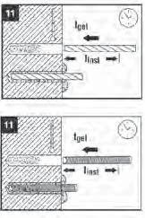
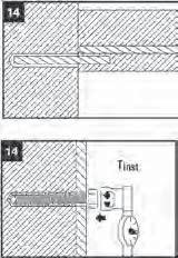
34 / Hammer Drilling Diamond Coring Hammer Drilling Check borehole conditions Borehole Cleaning instructions Borehole conditions / Installation direction Drilling depth Injection instructions Dry 10 inch (250 mm) HIT-SZ/IP not required Cleaning method 1 Horizontal and vertical Water saturated > 10 inch (250 mm) HIT-SZ/IP recommended Clean and dry Dry Cleaning method 2+1 Overhead All drilling depth HIT-SZ/IP required Water saturated Water-filled Cleaning method 2 Submerged Clean and water-filled All directions All drilling depth HIT-SZ/IP required / / / / / /

35 / / / / / / / / / / / / / /
36
37


38 / / / / / / / / / / / // / / / / / / / / / / / / / / / //// / / / / / / / / /// /// //// //// //// // / / / / / / / /// /// /// /// /// / /// / / /// / / / / / / / / /
39 February 26, 2010 To Whom It May Concern: Re: Hilti HIT RE-500-SD Epoxy Adhesive Anchor LEEDs Info The Hilti HIT RE-500-SD Epoxy Adhesive is manufactured in Germany. The amount of post-consumer and post-industrial material in the Hilti HIT RE-500-SD Epoxy Adhesive is not known and it cannot be recycled. The Hilti HIT RE-500-SD Epoxy Adhesive does not contain any Rapidly Renewable Materials. The VOC content in Hilti HIT RE-500-SD Epoxy Adhesive is 4.0 g/l. Hilti HIT RE-500-SD Epoxy Adhesive is not regulated as a hazardous waste by the Federal EPA Standards. The regulations for the disposal of non-regulated industrial waste can vary from state to state and even city to city. For this reason, you should consult your local and state regulatory agencies for direction on disposal. Please feel free to contact me at (918) if you have questions. Sincerely, Jerry Metcalf MPH, CHMM Safety/Environmental Manager Hilti Inc (918) jerry.metcalf@hilti.com Rev. Date: 2/26/10 Hilti, Inc South 122 nd East Avenue Tulsa, OK
40 MSDS No.: 318 Revision No.: 002 Revision Date: 05/17/12 Page: 1 of 2 Product name: Description: HIT RE 500 SD MATERIAL SAFETY DATA SHEET High strength epoxy adhesive for anchoring in concrete and rebar doweling. Part A is the large tube; Part B is the small tube. Supplier: Hilti, Inc. P.O. Box 21148, Tulsa, OK Emergency # (Chem-Trec.): (USA, PR, Virgin Islands, Canada); (other countries) INGREDIENTS AND EXPOSURE LIMITS Ingredients: CAS Number: TLV: PEL: STEL: Part A: Bisphenol A epoxy resin NE NE NE Bisphenol F epoxy resin NE NE NE Quartz sand mg/m 3 (R) 10 mg/m 3 % SiO NE Alkylglycidyl ether * NE NE NE Diglycidyl ether * NE NE NE Siloxanes & silicones NE NE NE Part B: m-xylene diamine NE NE C: 0.1 / S Aliphatic polyamine * NE NE NE Quartz sand mg/m 3 (R) 10 mg/m 3 % SiO NE Aluminum oxide mg/m 3 (R) 15 mg/m 3 (T) NE Cement NE NE NE Siloxanes & silicones NE NE NE Abbreviations: * = indicates New Jersey Trade Secret Registry Number. C = Ceiling. NE = None Established. R =dust respirable fraction. S = Skin exposure, including the mucous membranes, eyes, and skin. T = total dust. TLV = ACGIH Threshold Limit Values. PEL = OSHA Permissible Exposure Limits. STEL = ACGIH/OSHA Short Term Exposure Limit Appearance and Odor: A: Gray; B: red / paste. Amine-like odor. PHYSICAL DATA VOC Content: 4.0 g/l Boiling Point: Approx. 212 F Vapor Pressure: Not determined. Vapor Density: (air = 1) Not determined. Odor Threshold: Not determined Evaporation Rate: Not applicable. Solubility in Water: Insoluble. Specific Gravity: 1.5 ph: 11 (Part B with 1:1 water) FIRE AND EXPLOSION HAZARD DATA Flash Point: > 200 F Flammable Limits: Not applicable. Extinguishing Media: Special Fire Fighting Procedures: Unusual Fire and Explosion Hazards: CO 2, Dry Chemical, Foam, Water Spray. A self-contained breathing apparatus should be worn when fighting fires involving chemicals. None known. Thermal decomposition products can be formed including CO X, NO X, water and carbon. REACTIVITY DATA Stability: Stable. Hazardous Polymerization: Will not occur. Incompatibility: Decomposition Products: Conditions to Avoid: Strong acids and oxidizing agents. Thermal decomposition can yield CO X, NO X, water and carbon. Avoid temperature extremes that could shorten the shelf-life of this product. (See handling and storage requirements for recommended storage temperatures). HEALTH HAZARD DATA Known Hazards: Signs and Symptoms of Exposure: Part A: Eye and skin irritation. Possible skin sensitizer. Part B: Corrosive Part A: Can be irritating to the eyes and skin, Can cause skin sensitization with some individuals (itching, redness, swelling). Part B: Can cause eye and skin burns. Vapors can be irritating. If HILTI is a registered trademark of Hilti Corp.
41 Routes of Exposure: Carcinogenicity: Medical Conditions Aggravated by Exposure: swallowed, can cause burns. Contact. Inhalation. IARC classifies crystalline silica (quartz sand) as a Group I carcinogen based upon evidence among workers in industries where there has been long-term and chronic exposure (via inhalation) to silica dust; e.g. mining, quarry, stone crushing, refractory brick and pottery workers. This product does not pose a dust hazard; therefore, this classification is not relevant. Eye, skin, and respiratory conditions. EMERGENCY AND FIRST AID PROCEDURES Eyes: Skin: Inhalation: Ingestion: Other: Flush immediately with water for at least 15 minutes. Contact a Physician if symptoms occur. Wash immediately with soap and water. Contact a Physician if symptoms occur. If symptoms occur, move to fresh air. Contact a Physician if symptoms occur. Do not induce vomiting unless directed by a physician. Contact a Physician immediately. Referral to a physician is recommended if there is any question about the seriousness of the injury/exposure CONTROL MEASURES AND PERSONAL PROTECTIVE EQUIPMENT Ventilation: Eye Protection: Skin Protection: Respiratory Protection: General (natural or mechanically induced fresh air movements). Chemical Goggles recommended. Impermeable gloves recommended. Other protective clothing as required to prevent skin contact. None normally required. Where ventilation is inadequate to control vapors, use a NIOSHapproved respirator with organic vapor cartridges. PRECAUTIONS FOR SAFE HANDLING AND USE Handling and Storing Precautions: Spill Procedures: For industrial use only. Keep away from children. Use with adequate ventilation. Avoid contact with the eyes or skin. Practice good hygiene; i.e. wash after using and before eating or smoking. Store in a cool dry area between 41 and 77 F (5-25 C). Keep from freezing. Take up with an absorbent material and place in a container for proper disposal. REGULATORY INFORMATION Hazard Communication: HMIS Codes: DOT Shipping Name: IATA / ICAO Shipping Name: TSCA Inventory Status: SARA Title III, Section 313: EPA Waste Code(s): Waste Disposal Methods: This MSDS has been prepared in accordance with the federal OSHA Hazard Communication Standard 29 CFR Health 3, Flammability 1, Reactivity 0, PPE B Limited Quantity - LQ Amines, solid, corrosive, n.o.s. (M-xylenediamine), Class 8, UN3259, PG II Chemical components listed on TSCA inventory. This product does not contain any toxic chemicals which are subject to reporting under Section 313 of SARA Title III (40 CFR Part 372). Not regulated by EPA as a hazardous waste Consult with regulatory agencies or your corporate personnel for disposal methods that comply with local, state, and federal safety, health and environmental regulations. CONTACTS Customer Service: Technical Service: Health / Safety: Jerry Metcalf (x ) Emergency # (Chem-Trec): (USA, PR, Virgin Islands, Canada); (other countries) The information and recommendations contained herein are based upon data believed to be correct; however, no guarantee or warranty of any kind expressed or implied is made with respect to the information provided. MSDS 318, Page 2 of 2
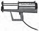
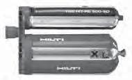
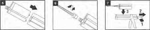
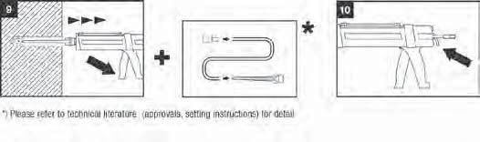
42 ICC-ES Evaluation Report (800) (562) ESR-2322* Reissued February 1, 2012 This report is subject to renewal April 1, A Subsidiary of the International Code Council DIVISION: CONCRETE Section: Concrete Anchors DIVISION: METALS Section: Post-Installed Concrete Anchors REPORT HOLDER: HILTI, INC SOUTH 122 ND EAST AVENUE TULSA, OKLAHOMA (800) HiltiTechEng@us.hilti.com EVALUATION SUBJECT: HILTI HIT-RE 500-SD ADHESIVE ANCHORS IN CONCRETE 1.0 EVALUATION SCOPE Compliance with the following codes: 2009, 2006, 2003 and 2000 International Building Code (IBC) 2009, 2006, 2003 and 2000 International Residential Code (IRC) Property evaluated: Structural 2.0 USES The Hilti HIT-RE 500-SD Adhesive Anchoring System is used to resist static, wind and seismic tension and shear loads in cracked and uncracked normal-weight concrete having a specified compressive strength, f c, of 2,500 psi to 8,500 psi (17.2 MPa to 58.6 MPa). The anchor system is an alternative to cast-in-place and post-installed anchors described in Sections 1911 and 1912 of the 2009 and 2006 IBC, or Sections 1912 and 1913 of the 2000 or 2003 IBC. The anchor systems may also be used where an engineered design is submitted in accordance with Section R of the 2009, 2006 and 2003 IRC, Section R of the 2003 IRC, or Section R of the 2000 IRC. 3.0 DESCRIPTION 3.1 General: The Hilti HIT-RE 500-SD Adhesive Anchoring System is comprised of the following components: Hilti HIT-RE 500-SD adhesive packaged in foil packs Adhesive mixing and dispensing equipment Equipment for hole cleaning and adhesive injection The Hilti HIT-RE 500-SD Adhesive Anchoring System may be used with continuously threaded rod, Hilti HIS-(R)N and HIS-RN internally threaded inserts or deformed steel reinforcing bars. The primary components of the Hilti Adhesive Anchoring System, including the Hilti HIT-RE 500-SD Adhesive, HIT-RE-M static mixing nozzle and steel anchoring elements, are shown in Figure 2 of this report. Installation information and parameters, as included with each adhesive unit package, are replicated as Figure 5 of this report. 3.2 Materials: Hilti HIT-RE 500-SD Adhesive: Hilti HIT-RE 500- SD Adhesive is an injectable two-component epoxy adhesive. The two components are separated by means of a dual-cylinder foil pack attached to a manifold. The two components combine and react when dispensed through a static mixing nozzle attached to the manifold. Hilti HIT-RE 500-SD is available in 11.1-ounce (330 ml), 16.9-ounce (500 ml), and 47.3-ounce (1400 ml) foil packs. The manifold attached to each foil pack is stamped with the adhesive expiration date. The shelf life, as indicated by the expiration date, corresponds to an unopened foil pack stored in a dry, dark environment Hole Cleaning Equipment: Hole cleaning equipment must be in accordance with Figure 5 of this report Dispensers: Hilti HIT-RE 500-SD must be dispensed with manual dispensers, pneumatic dispensers, or electric dispensers provided by Hilti Anchor Elements: Threaded Steel Rods: Threaded steel rods must be clean, continuously threaded rods (all-thread) in diameters as described in Tables 7 and 11 and Figure 5 of this report. Steel design information for common grades of threaded rods are provided in Table 2 and Table 3. Carbon steel threaded rods must be furnished with a millimeter-thick (5 μm) zinc electroplated coating complying with ASTM B 633 SC 1 or must be hot-dipped galvanized complying with ASTM A 153, Class C or D. Threaded steel rods must be straight and free of indentations or other defects along their length. The ends may be stamped with identifying marks and the embedded end may be blunt cut or cut on the bias (chisel point). *Revised March 2013 ICC-ES Evaluation Reports are not to be construed as representing aesthetics or any other attributes not specifically addressed, nor are they to be construed as an endorsement of the subject of the report or a recommendation for its use. There is no warranty by ICC Evaluation Service, LLC, express or implied, as to any finding or other matter in this report, or as to any product covered by the report. Copyright 2013 Page 1 of
43 ESR-2322 Most Widely Accepted and Trusted Page 2 of Steel Reinforcing Bars: Steel reinforcing bars are deformed bars (rebar). Tables 23, 27 and 31 and Figure 5 summarize reinforcing bar size ranges. See Table 6 for specifications of common reinforcing bar types and grades. The embedded portions of reinforcing bars must be straight, and free of mill scale, rust and other coatings that may impair the bond with the adhesive. Reinforcing bars must not be bent after installation, except as set forth in Section of ACI 318 with the additional condition that the bars must be bent cold, and heating of reinforcing bars to facilitate field bending is not permitted HIS-N and HIS-RN Inserts: Hilti HIS-N and HIS- RN inserts have a profile on the external surface and are internally threaded. Mechanical properties for HIS-N and HIS-RN inserts are provided in Table 4. The inserts are available in diameters and lengths as shown in Tables 15 and 19 and Figure 5. HIS-N inserts are produced from carbon steel and furnished either with a millimeterthick (5 μm) zinc electroplated coating complying with ASTM B 633 SC 1 or a hot-dipped galvanized coating complying with ASTM A 153, Class C or D. The stainless steel HIS-RN inserts are fabricated from X5CrNiMo17122 K700 steel conforming to DIN Specifications for common bolt types that may be used in conjunction with HIS-N and HIS-RN inserts are provided in Table 5. Bolt grade and material type (carbon, stainless) must be matched to the insert. Strength reduction factors, φ, corresponding to brittle steel elements must be used for HIS-N and HIS-RN inserts Ductility: In accordance with ACI 318 Appendix D, in order for a steel element to be considered ductile, the tested elongation must be at least 14 percent and reduction of area must be at least 30 percent. Steel elements with a tested elongation less than 14 percent or a reduction of area less than 30 percent, or both, are considered brittle. Values for various common steel materials are provided in Tables 2, 3 and 5 of this report. 3.3 Concrete: Normal-weight concrete must comply with Section 1903 and 1095 of the IBC. The specified compressive strength of concrete must be from 2,500 psi to 8,500 psi (17.2 MPa to 58.6 MPa). 4.0 DESIGN AND INSTALLATION 4.1 Strength Design: General: Anchor design strengths, N n and V n, must be determined in accordance with ACI (2009 IBC) or ACI Appendix D and this report. A design example is given in Figure 4 of this report. Design parameters are provided in Tables 5 through 10 of this report. Design strengths must be determined in accordance with ACI , as an alternative to the 2000 and 2003 IBC, and Section R301.1 of the IRC. Design parameters are based on the 2009 IBC (ACI ) unless noted otherwise in Sections D through of this report. The anchor design must satisfy the requirements of ACI 318 Sections D and D Strength reduction factors,, described in ACI 318 Section D.4.4, and noted in Tables 5 through 10 of this report, must be used for load combinations calculated in accordance with Section of the IBC and ACI 318 Section 9.2. Strength reductions factors,, described in ACI 318 Section D.4.5 must be used for load combinations calculated in accordance with Appendix C of ACI 318. This section provides amendments to ACI 318 Appendix D as required for the strength design of adhesive anchors. In conformance with ACI 318, all equations are expressed in inch-pound units. Modify ACI 318 D as follows: D In Eq. (D-1) and (D-2), N n and V n are the lowest design strengths determined from all appropriate failure modes. N n is the lowest design strength in tension of an anchor or group of anchors as determined from consideration of N sa, either N a or N ag, and either N cb or N cbg. V n is the lowest design strength in shear of an anchor or a group of anchors as determined from consideration of V sa, either V cb or V cbg, and either V cp or V cpg. For adhesive anchors subject to tension resulting from sustained loading, refer to D for additional requirements. Add ACI 318 D as follows: D For adhesive anchors subjected to tension resulting from sustained loading, a supplementary design analysis shall be performed using Eq. (D-1) whereby N ua is determined from the sustained load alone, e.g., the dead load and that portion of the live load acting that may be considered as sustained and N n is determined as follows: D For single anchors: N n = 0.75N ao. D For anchor groups, Equation (D-1) shall be satisfied by taking N n = 0.75N ao for that anchor in an anchor group that resists the highest tension load. D Where shear loads act concurrently with the sustained tension load, interaction of tension and shear shall be analyzed in accordance with ACI 318 Section D Static Steel Strength in Tension: The nominal strength of an anchor in tension as governed by the steel, N sa, in accordance with ACI 318 Section D and strength reduction factors in accordance with ACI 318 Section D.4.4 are given in the tables outlined in Table 1 for the corresponding anchor steel Static Concrete Breakout Strength in Tension: The nominal concrete breakout strength in tension, N cb or N cbg, must be calculated in accordance with ACI 318 D.5.2 with the following addition: D (2006 IBC) or D (2009 IBC) The limiting concrete strength of adhesive anchors in tension shall be calculated in accordance withd to D under the 2009 IBC or D to D under the 2006 IBC where the value of k c to be used in Eq. (D-7) shall be: k c,cr = 17 where analysis indicates cracking at service load levels in the anchor vicinity (cracked concrete) k c,uncr = 24 where analysis indicates no cracking at service load levels in the anchor vicinity (uncracked concrete) Additional information for the determination of the nominal concrete breakout strength (N cb or N cbg ) is given in the tables outlined in Table 1 for the corresponding anchor steel. The value of f c must be limited to a maximum of 8,000 psi (55 MPa) in accordance with ACI 318 Section D Static Pullout Strength in Tension: In lieu of determining the nominal pullout strength in accordance with ACI 318 D.5.3, nominal bond strength in tension must be calculated in accordance with the following sections added to ACI 318: D The nominal bond strength of an adhesive anchor, N a, or group of adhesive anchors, N ag, in tension shall not exceed
44 ESR-2322 Most Widely Accepted and Trusted Page 3 of 44 (a) For a single anchor N a = A Na A Na0 ψ ed,na ψ p,na N a0 (b) For a group of anchors N ag = A Na A Na0 ψ ed,na ψ g,na ψ ec,na ψ p,na N a0 where: (D-16a) (D-16b) A na is the projected area of the failure surface for the single anchor or group of anchors that shall be approximated as the base of the rectilinear geometrical figure that results from projecting the failure surface outward a distance c cr,na from the centerlines of the single anchor, or in the case of a group of anchors, from a line through a row of adjacent anchors. A na shall not exceed na na0 where n is the number of anchors in tension in the group. In ACI 318 Figures RD.5.2.1a and RD.5.2.1b, the terms 1.5h ef and 3.0h ef shall be replaced with c cr,na and s cr,na, respectively. A Na0 is the projected area of the failure surface of a single anchor without the influence of proximate edges in accordance with Eq. (D-16c): A na0 = (s cr,na ) 2 (D-16c) with s cr,na = as given by Eq. (D-16d) D The critical spacing s cr,na and critical edge distance c cr,na shall be calculated as follows: s cr,na = 20 d τ k,uncr 1,450 3h ef (D-16d) c cr,na = S cr,na 2 (D-16e) D The basic strength of a single adhesive anchor in tension in cracked concrete shall not exceed N a0 =τ k,cr π d h ef where (D-16f) τ k,cr is the characteristic bond strength in cracked concrete D The modification factor for the influence of the failure surface of a group of adhesive anchors is ψ g,na =ψ g,na0 + where: s s cr,na ψ g,na = n- n-1 τ 1.5 k,cr 1.0 τ k,max,cr where: ψg,Na0 (D-16g) (D-16h) n = the number of tension-loaded adhesive anchors in a group. τ k,max,cr = k c,cr π d h ef f' c (D-16i) The value of f c must be limited to maximum of 8,000 psi (55 MPa) in accordance with ACI 318 Section D.3.5. D The modification factor for eccentrically loaded adhesive anchor groups is ψ ec,na = e' N s cr,na 1.0 (D-16j) s Eq. (D-16j) is valid for e' N 2 If the loading on an anchor group is such that only certain anchors are in tension, only those anchors that are in tension shall be considered when determining the eccentricity, e N, for use in Eq. (D-16j). In the case where eccentric loading exists about two orthogonal axes, the modification factor Ψ ec,na shall be computed for each axis individually and the product of these factors used as Ψ ec,na in Eq. (D-16b). D The modification factor for the edge effects for single adhesive anchors or anchor groups loaded in tension is: Ψ ed,na = 1.0 for c a,min c cr,na (D-16l) or ψ ed,na = c a,min c cr,na 1.0 when c amin < c cr,na (D-16m) D When an adhesive anchor or a group of adhesive anchors is located in a region of a concrete member where analysis indicates no cracking at service load levels, the nominal strength, N a or N ag, of a single adhesive anchor or a group of adhesive anchors shall be calculated according to Eq. (D-16a) and Eq. (D-16b) with τ k,cr substituted for τ k,cr in the calculation of the basic strength N ao in accordance with Eq. (D-16f). The factor Ψ g,na0 shall be calculated in accordance with Eq. (D-16h) whereby the value of τ k,max,uncr shall be calculated in accordance with Eq. (D-16n) and substituted for τ k,max,cr in Eq. (D-16h). τ k,max,uncr = k c,uncr h π d ef f' c (D-16n) D When an adhesive anchor or a group of adhesive anchors is located in a region of a concrete member where analysis indicates no cracking at service load levels, the modification factor Ψ p,na shall be taken as ψ p,na = 1.0 when c a,min c ac (D-16o) ψ p,na = c a,min; c cr,na c ac when c a,min < c ac (D-16p) where c ac must be determined in accordance with Section of this report. For all other cases: ψ p,na = 1.0 Additional information for the determination of nominal bond strength in tension is given in Section Static Steel Strength in Shear: The nominal static strength of an anchor in shear as governed by the steel, V sa, in accordance with ACI 318 Section D and strength reduction factors are given in the tables outlined in Table 1 for the corresponding anchor steel Static Concrete Breakout Strength in Shear: The nominal concrete breakout strength of a single anchor or group of anchors in shear, V cb or V cbg, must be calculated in accordance with ACI 318 Section D.6.2 based on information given in the tables outlined in Table 1 for the corresponding anchor steel. The basic concrete breakout strength of a single anchor in shear, V b, must be calculated
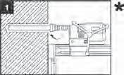
45 ESR-2322 Most Widely Accepted and Trusted Page 4 of 44 in accordance with ACI 318 Section D using the values of d and h ef given in the tables as outlined in Table 1 for the corresponding anchor steel in lieu of d o and l e, respectively. In no case must h ef exceed 8d o. The value of f c must be limited to a maximum of 8,000 psi (55 MPa) in accordance with ACI 318 Section D Static Concrete Pryout Strength in Shear: In lieu of determining the nominal pryout strength in accordance with ACI 318 Section D.6.3.1, nominal pryout strength in shear must be calculated in accordance with the following sections added to ACI 318: D The nominal pryout strength of a single adhesive anchor V cp or group of adhesive anchors V cpg shall not exceed: (a) for a single adhesive anchor: V cp = min k cp N a ; k cp N cb (D-30a) (b) for a group of adhesive anchors: V cpg = min k cp N ag ; k cp N cbg (D-30b) where: k cp = 1.0 for h ef < 2.5 in. (64 mm) k cp = 2.0 for h ef 2.5 in. (64 mm) N a shall be calculated in accordance with Eq. (D-16a) N ag shall be calculated in accordance with Eq. (D-16b) N cb,n cbg are determined in accordance with D to D Bond Strength Determination: Bond strength values are a function of concrete condition (cracked, uncracked), drilling method (hammer drill, core drill) and installation conditions (dry, water-saturated, etc.). Bond strength values must be modified with the factor κ nn for cases where holes are drilled in water-saturated concrete (κ ws ), where the holes are water-filled at the time of anchor installation (κ wf ), or where the anchor installation is conducted underwater (κ uw ) as follows: C O N C R E T E T Y P E S C R A C K E D U N C R A C K E D H O L E D R I L L I N G M E T H O D PERMISSIBLE INSTALLATION CONDITIONS BOND STRENGTH ASSOCIATED STRENGTH REDUCTION FACTOR Dry concrete τ k,cr φ d Water-saturated τ k,cr Κ ws φ ws Dry concrete τ k,uncr φ d Water-saturated τ k,uncr Κ ws φ ws Water-filled hole τ k,uncr Κ wf φ wf Underwater application τ k,uncr Κ uw φ uw Dry concrete τ k,uncr φ d Water saturated τ k,uncr Κ ws φ ws Figure 3 presents a selection flowchart. Where applicable, the modified bond strength values must be used in lieu of τ k,cr and τ k,uncr in Equations (D-16d), (D-16f), (D-16h) and (D-16j). The resulting nominal bond strength must be multiplied by the associated strength reduction factor φ nn Minimum Member Thickness h min, Anchor Spacing s min and Edge Eistance c min : In lieu of ACI 318 Section D.8.3, values of c min and s min described in this report must be observed for anchor design and installation. Likewise, in lieu of ACI 318 Section D.8.5, the minimum member thicknesses, h min, described in this report must be observed for anchor design and installation. In determining minimum edge distance, c min, the following section must be added to ACI 318: D.8.8 For adhesive anchors that will remain untorqued, the minimum edge distance shall be based on minimum cover requirements for reinforcement in Section 7.7. For adhesive anchors that will be torqued, the minimum edge distance and spacing shall be taken as 6d o and 5d o, respectively Critical Edge Distance c ac : In lieu of ACI 318 D.8.6, c ac must be determined as follows: c ac =h ef τ k,uncr max h ; 1.4 Eq. (4-1) h ef where τ k,uncr is the characteristic bond strength in uncracked concrete, h is the member thickness, and h ef is the embedment depth. τk,uncr need not be taken as greater than: τ k,uncr = k uncrh ef f ' c π d For edge distance c a1 =1.75 inch (45 mm) T max must be reduced according to the table provided below: Edge distance, c a1, in. (mm) Element spacing, s, in. (mm) T max 1.75 (45) 5φ 0.30 T max 1.75 (45) 16 (406) 0.50 T max Design Strength in Seismic Design Categories C, D, E and F: In structures assigned Design Category C, D, E or F under the IBC or IRC, the anchor strength must be adjusted in accordance with 2009 IBC Section or 2006 IBC Section The nominal steel shear strength, V sa, must be adjusted by α V,seis as given in the tables summarized in Table 1 for the corresponding anchor steel. The nominal bond strength τ k,cr must be adjusted by α N,seis as given in the tables summarized in Table 1 for the corresponding anchor steel Interaction of Tensile and Shear Forces: For designs that include combined tension and shear, the interaction of tension and shear loads must be calculated in accordance with ACI 318 Section D Allowable Stress Design: General: For anchors designed using load combinations in accordance with IBC Section (Allowable Stress Design), allowable loads must be established using the equations below: T allowable,asd = ϕn n α and V allowable,asd = ϕv n α where T allowable,asd = Allowable tension load (lbf or kn) V allowable,asd = Allowable shear load (lbf or kn) Eq. (4-2) Eq. (4-3) φn n = Lowest design strength of an anchor or anchor group in tension as determined in accordance with ACI 318 Appendix D with amendments in Section 3.3 of this criteria, 2009 IBC Sections and and 2006 IBC Section
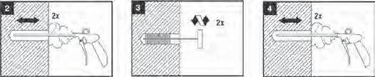
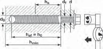
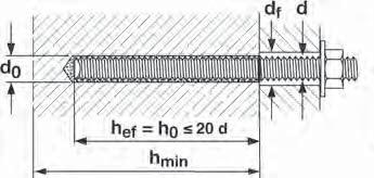
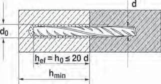
46 ESR-2322 Most Widely Accepted and Trusted Page 5 of 44 φv n = Lowest design strength of an anchor or anchor group in shear as determined in accordance with ACI 318 Appendix D with amendments in Section 3.3 of this criteria, 2009 IBC Sections and and 2006 IBC Section α = Conversion factor calculated as a weighted average of the load factors for the controlling load combination. In addition, α must include all applicable factors to account for non-ductile failure modes and required over-strength. Limits on edge distance, anchor spacing and member thickness described in this report must apply. Example calculations are provided in Table Interaction of Tensile and Shear Forces: Interaction shall be calculated in accordance with ACI 318 Section D.7 as follows: For shear loads V 0.2V allowable,asd, the full allowable load in tension shall be permitted. For tension loads T 0.2T allowable, ASD, the full allowable load in shear shall be permitted. For all other cases: T + T allowable,asd V V allowable,asd 1.2 Eq. (4-3) 4.3 Installation: Installation parameters are illustrated in Figure 1. Installation of the Hilti HIT-RE 500-SD Adhesive Anchor System must conform to the manufacturer's published installation instructions included in each unit package as described in Figure 5 of this report. Anchor locations must comply with this report and the plans and specifications approved by the code official. 4.4 Special Inspection: Periodic special inspection must be performed where required in accordance with Section of the 2009 IBC, Sections and of the 2006, 2003 or 2000 IBC, whereby periodic special inspection is defined in Section of the IBC and this report. The special inspector must be on the jobsite during anchor installation to verify anchor type, anchor dimensions, concrete type, concrete compressive strength, hole dimensions, hole cleaning procedures, anchor spacing, edge distances, concrete thickness, anchor embedment, and tightening torque. The special inspector must verify the initial installations of each type and size of adhesive anchor by construction personnel on site. Subsequent installations of the same anchor type and size by the same construction personnel must be permitted to be performed in the absence of the special inspector. Any change in the anchor product being installed or the personnel performing the installation must require an initial inspection. For ongoing installations over an extended period, the special inspector must make regular inspections to confirm correct handling and installation of the product. Continuous special inspection is required for all cases where anchors installed overhead (vertical up) are designed to resist sustained tension loads. Under the IBC, additional requirements as set forth in Sections 1705 and 1706 must be observed, where applicable. 5.0 CONDITIONS OF USE The Hilti HIT-RE 500-SD Adhesive Anchor System described in this report complies with the codes listed in Section 1.0 of this report, subject to the following conditions: 5.1 Hilti HIT-RE 500-SD adhesive anchors must be installed in accordance with the manufacturer's published installation instructions as included in the adhesive packaging and described in Figure 5 of this report. 5.2 The anchors must be installed in cracked and uncracked normal-weight concrete having a specified compressive strength f c = 2,500 psi to 8,500 psi (17.2 MPa to 58.6 MPa). 5.3 The values of f c used for calculation purposes must not exceed 8,000 psi (55.1 MPa) 5.4 Anchors must be installed in concrete base materials in holes predrilled in accordance with the instructions in Figure Loads applied to the anchors must be adjusted in accordance with Section of the 2009, 2006, 2003 or 2000 IBC for strength design and in accordance with Section of the 2009, 2006, 2003 or 2000 IBC for allowable stress design. 5.6 Hilti HIT-RE 500-SD adhesive anchors are recognized for use to resist short- and long-term loads, including wind and earthquake, subject to the conditions of this report. 5.7 In structures assigned to Seismic Design Category C, D, E or F under the IBC or IRC, anchor strength must be adjusted in accordance with 2009 IBC Section or 2006 IBC Section Hilti HIT-RE 500-SD adhesive anchors are permitted to be installed in concrete that is cracked or that may be expected to crack during the service life of the anchor, subject to the conditions of this report. 5.9 Strength design values are established in accordance with Section 4.1 of this report Allowable design values are established in accordance with Section 4.2 of this report Minimum anchor spacing and edge distance as well as minimum member thickness must comply with the values described in this report The minimum anchor embedment for threaded rods (Tables 2 and 3) is limited to the following values: d [in.] h ef,min [in.] d [mm] h ef,min [mm] 3 / 8 1 / 2 5 / 8 3 / 4 7 / / / / / / / / 2 4d 4d 4d d 4d 4d The maximum anchor embedment for all anchor materials is limited to maximum of 20 times the outer diameter d of the fastening element Prior to installation, calculations and details demonstrating compliance with this report must be submitted to the building official. The calculations and details must be prepared by a registered design professional where required by the statutes of the jurisdiction in which the project is to be constructed.
47 ESR-2322 Most Widely Accepted and Trusted Page 6 of Anchors are not permitted to support fire-resistive construction. Where not otherwise prohibited in the code, Hilti HIT-RE 500-SD adhesive anchors are permitted for installation in fire-resistive construction provided that at least one of the following conditions is fulfilled: Anchors are used to resist wind or seismic forces only. Anchors that support gravity load bearing structural elements are within a fire-resistive envelope or a fire-resistive membrane, are protected by approved fire-resistive materials, or have been evaluated for resistance to fire exposure in accordance with recognized standards. Anchors are used to support nonstructural elements Since an ICC-ES acceptance criteria for evaluating data to determine the performance of adhesive anchors subjected to fatigue or shock loading is unavailable at this time, the use of these anchors under such conditions is beyond the scope of this report Use of zinc-plated carbon steel anchors is limited to dry, interior locations Periodic special inspection must be provided in accordance with Section 4.4 of this report. Continuous special inspection for overhead installations (vertical up) that are designed to resist sustained tension loads must be provided in accordance with Section 4.4 of this report Hilti HIT-RE 500-SD adhesives are manufactured by Hilti GmbH, Kaufering, Germany, with quality control inspections by UL LLC (AA-668) Hilti HIS-N and HIS-RN inserts are manufactured by Hilti (China) Ltd., Guangdong, China, with quality control inspections by UL LLC (AA-668). 6.0 EVIDENCE SUBMITTED Data in accordance with the ICC-ES Acceptance Criteria for Post-installed Adhesive Anchors in Concrete (AC308), dated November 2009, including but not limited to tests under freeze/thaw conditions (Table 4.2, test series 6). 7.0 IDENTIFICATION 7.1 Hilti HIT-RE 500-SD adhesive is identified by packaging labeled with the manufacturer's name (Hilti Corp.) and address, anchor name, evaluation report number (ICC-ES ESR-2322), and the name of the inspection agency (UL LLC). 7.2 HIS-N and HIS-RN inserts are identified by packaging labeled with the manufacturer's name (Hilti Corp.) and address, anchor name, evaluation report number (ICC-ES ESR-2322), and the name of the inspection agency (UL LLC). 7.3 Threaded rods, nuts, washers, bolts, cap screws, and deformed reinforcing bars are standard elements and must conform to applicable national or international specifications.

48 ESR-2322 Most Widely Accepted and Trusted Page 7 of 44 ALL-THREAD OR REBAR c T max c s BOLT OR STUD T max HILTI HIS/HIS-R INTERNALLY THREADED INSERT h s d h ef h d h ef h d bit d bit THREADED ROD/REINFORCING BAR FIGURE 1 INSTALLATION PARAMETERS HIS AND HIS-R INSERTS FIGURE 2 FLOW CHART FOR THE ESTABLISHMENT OF DESIGN BOND STRENGTH TABLE 1 DESIGN TABLE INDEX Design strength 1 Threaded rod Hilti HIS internally threaded insert Deformed reinforcement fractional metric fractional metric fractional metric Canadian Steel N sa, V sa Table 7 Table 11 Table 15 Table 19 Table 23 Table 27 Table 31 Concrete N pn, N sb, N sbg, N cb, N cbg, V cb, V cbg, V cp, V cpg Table 8 Table 12 Table 16 Table 20 Table 24 Table 28 Table 32 Bond 2 N a, N ag hammer-drilled holes diamond cored holes Table 9 Table 13 Table 17 Table 21 Table 25 Table 29 Table 33 Table 10 Table 14 Table 18 Table 22 Table 26 Table 30 Table 34 1 Ref. ACI D See Section 4.1 of this evaluation report
49 ESR-2322 Most Widely Accepted and Trusted Page 8 of 44 TABLE 2 SPECIFICATIONS AND PHYSICAL PROPERTIES OF COMMON CARBON STEEL THREADED ROD MATERIALS 1 THREADED ROD SPECIFICATION ASTM A Grade B7 2 1 / 2 in. ( 64 mm) ASTM F 568M 3 Class 5.8 M5 ( 1 / 4 in.) to M24 (1 in.) (equivalent to ISO 898-1) ISO Class 5.8 ISO Class 8.8 Minimum specified ultimate strength, f uta Minimum specified yield strength 0.2 percent offset, f ya psi 125, ,000 (MPa) (862) (724) f uta /f ya Elongation, min. percent 5 Reduction of Area, min. percent Specification for nuts ASTM A 194 MPa DIN 934 (8-A2K) (psi) (72,500) (58,000) ASTM A 563 Grade DH 7 MPa (psi) 500 (72,500) 400 (58,000) MPa (psi) (116,000) (92,800) DIN 934 (8-A2K) DIN 934 (8-A2K) 1 Hilti HIT-RE 500-SD must be used with continuously threaded carbon steel rod (all-thread) have thread characteristics comparable with ANSI B1.1 UNC Coarse Thread Series or ANSI B1.13M M Profile Metric Thread Series. Values for threaded rod types and associated nuts supplied by Hilti are provided here. 2 Standard Specification for Alloy-Steel and Stainless Steel Bolting Materials for High-Temperature Service 3 Standard Specification for Carbon and Alloy Steel Externally Threaded Metric Fasteners 4 Mechanical properties of fasteners made of carbon steel and alloy steel Part 1: Bolts, screws and studs 5 Based on 2-in. (50 mm) gauge length except for A 193, which are based on a gauge length of 4d and ISO 898, which is based on 5d. 6 Nuts of other grades and styles having specified proof load stresses greater than the specified grade and style are also suitable. Nuts must have specified proof load stresses equal to or greater than the minimum tensile strength of the specified threaded rod. 7 Nuts for fractional rods. TABLE 3 SPECIFICATIONS AND PHYSICAL PROPERTIES OF COMMON STAINLESS STEEL THREADED ROD MATERIALS 1 THREADED ROD SPECIFICATION Minimum specified ultimate strength, f uta Minimum specified yield strength 0.2 percent offset, f ya f uta /f ya Elongation, min. percent Reduction of Area, min. percent Specification for nuts 4 ASTM F CW1 (316) 1 / 4 to 5 / 8 in. psi 100,000 65,000 (MPa) (689) (448) ASTM F 594 Alloy group 1, 2 or 3 ASTM F CW2 (316) 3 / 4 to 1 1 / 2 in. psi 85,000 45,000 (MPa) (586) (310) 1, ASTM F 594 Alloy group 1, 2, or 3 ISO A4-70 M8 M24 ISO A4-50 M27 M30 MPa (psi) (101,500) (65,250) MPa (psi) (72,500) (30,450) ISO ISO Hilti HIT-RE 500-SD must be used with continuously threaded stainless steel rod (all-thread) that have thread characteristics comparable with ANSI B1.1 UNC Coarse Thread Series or ANSI B1.13M M Profile Metric Thread Series. Values for threaded rod types and associated nuts supplied by Hilti are provided here. 2 Standard Steel Specification for Stainless Steel Bolts, Hex Cap Screws, and Studs 3 Mechanical properties of corrosion-resistant stainless steel fasteners Part 1: Bolts, screws and studs. 4 Nuts of other grades and styles having specified proof load stresses greater than the specified grade and style are also suitable. Nuts must have specified proof load stresses equal to or greater than the minimum tensile strength of the specified threaded rod.
50 ESR-2322 Most Widely Accepted and Trusted Page 9 of 44 TABLE 4 SPECIFICATIONS AND PHYSICAL PROPERTIES OF U.S. CUSTOMARY UNIT AND METRIC HIS-N AND HIS-RN INSERTS HILTI HIS-N AND HIS-RN INSERTS Carbon Steel DIN EN SMnPb30+c or DIN SMnPb28K 3 / 8 and M8 to M10 Carbon Steel DIN EN SMnPb30+c or DIN SMnPb28K 1 / 2 to 3 / 4 and M12 to M20 Stainless Steel EN X5CrNiMo Minimum specified ultimate strength, f uta Minimum specified yield strength, f ya MPa (psi) (71,050) (59,450) MPa (psi) (66,700) (54,375) MPa (psi) (101,500) (50,750) TABLE 5 SPECIFICATIONS AND PHYSICAL PROPERTIES OF COMMON BOLTS, CAP SCREWS AND STUDS FOR USE WITH HIS-N AND HIS-RN INSERTS 1,2 BOLT, CAP SCREW OR STUD SPECIFICATION SAE J429 3 Grade 5 Minimum specified ultimate strength f uta Minimum specified yield strength 0.2 percent offset f ya psi 120,000 92,000 (MPa) (828) (634) f uta /f ya Elongation, min. Reduction of Area, min. Specification for nuts SAE J995 ASTM A / 2 to 1-in. psi 120,000 92,000 (MPa) (828) (634) A 563 C, C3, D, DH, DH3 Heavy Hex ASTM A193 5 Grade B8M (AISI 316) for use with HIS- RN psi 110,000 95,000 (MPa) (759) (655) ASTM F Alloy Group 1, 2 or 3 ASTM A193 5 Grade B8T (AISI 321) for use with HIS- RN psi 125, ,000 (MPa) (862) (690) ASTM F Alloy Group 1, 2 or 3 1 Minimum Grade 5 bolts, cap screws or studs must be used with carbon steel HIS inserts. 2 Only stainless steel bolts, cap screws or studs must be used with HIS-RN inserts. 3 Mechanical and Material Requirements for Externally Threaded Fasteners 4 Standard Specification for Structural Bolts, Steel, Heat Treated, 120/105 ksi Minimum Tensile Strength 5 Standard Specification for Alloy-Steel and Stainless Steel Bolting Materials for High-Temperature Service 6 Nuts must have specified minimum proof load stress equal to or greater than the specified minimum full-size tensile strength of the specified stud. 7 Nuts for stainless steel studs must be of the same alloy group as the specified bolt, cap screw, or stud. TABLE 6 SPECIFICATIONS AND PHYSICAL PROPERTIES OF COMMON STEEL REINFORCING BARS REINFORCING BAR SPECIFICATION ASTM A Gr. 60 ASTM A Gr. 40 DIN BSt 500 CAN/CSA-G Gr. 400 Minimum specified ultimate strength, f uta Minimum specified yield strength, f ya psi 90,000 60,000 (MPa) (620) (414) psi 60,000 40,000 (MPa) (414) (276) MPa (psi) (79,750) (72,500) MPa (psi) (78,300) (58,000) 1 Standard Specification for Deformed and Plain Carbon Steel Bars for Concrete Reinforcement 2 Reinforcing steel; reinforcing steel bars; dimensions and masses 3 Billet-Steel Bars for Concrete Reinforcement
51 ESR-2322 Most Widely Accepted and Trusted Page 10 of 44 TABLE 7 STEEL DESIGN INFORMATION FOR U.S. CUSTOMARY UNIT THREADED ROD 1 DESIGN INFORMATION Symbol Units 3 / 8 1 / 2 Nominal rod diameter (in.) 5 / 3 8 / 4 7 / / 4 Rod O.D. Rod effective cross-sectional area ISO Class Nominal strength as governed by steel strength Reduction for seismic shear d A se N sa V sa in (mm) (9.5) (12.7) (15.9) (19.1) (22.2) (25.4) (31.8) in (mm 2 ) (50) (92) (146) (216) (298) (391) (625) lb 5,620 10,290 16,385 24,250 33,470 43,910 70,260 (kn) (25.0) (45.8) (72.9) (107.9) (148.9) (195.3) (312.5) lb 2,810 6,175 9,830 14,550 20,085 26,345 42,155 (kn) (12.5) (27.5) (43.7) (64.7) (89.3) (117.2) (187.5) α V,seis Strength reduction factor φ for tension 2 φ Strength reduction factor φ for shear 2 φ ASTM A 193 B7 2 Nominal strength as governed by steel strength Reduction for seismic shear N sa V sa lb 9,685 17,735 28,250 41,810 57,710 75, ,135 (kn) (43.1) (78.9) (125.7) (186.0) (256.7) (336.8) (538.8) lb 4,845 10,640 16,950 25,085 34,625 45,425 72,680 (kn) (21.5) (47.3) (75.4) (111.6) (154.0) (202.1) (323.3) α V,seis Strength reduction factor φ for tension 2 φ Strength reduction factor φ for shear 2 φ ASTM F593, CW Stainless 2 Nominal strength as governed by steel strength Reduction for seismic shear N sa V sa lb 7,750 14,190 22,600 28,430 39,245 51,485 82,370 (kn) (34.5) (63.1) (100.5) (126.5) (174.6) (229.0) (366.4) lb 3,875 8,515 13,560 17,060 23,545 30,890 49,425 (kn) (17.2) (.37.9) (60.3) (75.9) (104.7) (137.4) (219.8) α V,seis Strength reduction factor φ for tension 2 φ Strength reduction factor φ for shear 2 φ For SI: 1 inch 25.4 mm, 1 lbf = N, 1 psi = MPa. For pound-inch units: 1 mm = inches, 1 N = lbf, 1 MPa = psi 1 Values provided for common rod material types are based on specified strengths and calculated in accordance with ACI 318 Eq. (D-3) and Eq. (D-20). Nuts and washers must be appropriate for the rod. 2 For use with the load combinations of ACI 318 Section 9.2, as set forth in ACI 318 D.4.4.
52 ESR-2322 Most Widely Accepted and Trusted Page 11 of 44 TABLE 8 CONCRETE BREAKOUT DESIGN INFORMATION FOR U.S. CUSTOMARY UNIT THREADED ROD 1 DESIGN INFORMATION Symbol Units 3 / 8 1 / 2 Nominal rod diameter (in.) 5 / 3 8 / 4 7 / / 4 Effectiveness factor for cracked concrete Effectiveness factor for uncracked concrete k in-lb 17 c,cr (SI) (7.1) in-lb 24 k c,uncr (SI) (10) Min. anchor spacing 3 Min. edge distance 3 s min c min in. 1 7 / / / / / / 4 (mm) (48) (64) (79) (95) (111) (127) (159) in. 1 7 / / / / / / 4 (mm) (48) (64) (79) (95) (111) (127) (159) in. h ef / 4 Minimum member thickness h min h ef + 2d 0 (mm) (h ef + 30) Critical edge distance splitting c ac - See Section of this report. (for uncracked concrete) Strength reduction factor for tension, concrete failure φ modes, Condition B 2 Strength reduction factor for shear, concrete failure modes, Condition B 2 φ For SI: 1 inch 25.4 mm, 1 lbf = N, 1 psi = MPa. For pound-inch units: 1 mm = inches, 1 N = lbf, 1 MPa = psi 1 Additional setting information is described in Figure 5, installation instructions. 2 Values provided for post-installed anchors under Condition B without supplementary reinforcement as defined in ACI 318 Section D For installations with 1 3 / 4 inch edge distance refer to Section for spacing and maximum torque requirements.
53 ESR-2322 Most Widely Accepted and Trusted Page 12 of 44 TABLE 9 BOND STRENGTH DESIGN INFORMATION FOR U.S. CUSTOMARY UNIT THREADED ROD 1,4 DESIGN INFORMATION Symbol Units 3 / 8 1 / 2 Nominal rod diameter (in.) 5 / 3 8 / 4 7 / / 4 Temperature range A 3 Temperature range B 3 Characteristic bond strength and minimum anchor embedment in cracked concrete Characteristic bond strength and minimum anchor embedment in uncracked concrete Characteristic bond strength and minimum anchor embedment in cracked concrete 2 Characteristic bond strength and minimum anchor embedment in uncracked concrete 2 τ psi 1,090 1,075 1,045 1, k,cr (MPa) (7.5) (7.4) (7.2) (6.9) (6.3) (5.9) (5.0) h ef,min in. (mm) See Section 5.12 τ k,uncr (MPa) (15.7) (15.4) (14.8) (14.3) (13.8) (13.4) (12.8) Psi 2,285 2,235 2,140 2,065 2,000 1,945 1,860 h ef,min in. (mm) See Section 5.12 τ k,cr (MPa) (3.1) (3.0) (2.6) (2.4) (2.2) (2.0) (1.8) Psi h ef,min in. (mm) See Section 5.12 τ k,uncr (MPa) (5.4) (5.3) (5.1) (4.9) (4.8) (4.6) (4.4) Psi h ef,min in. (mm) See Section 5.12 Dry concrete φ d Permissible installation conditions Water-saturated concrete Water-filled hole Underwater application φ ws κ ws φ wf κ wf φ uw κ uw For SI: 1 inch 25.4 mm, 1 lbf = N, 1 psi = MPa. For pound-inch units: 1 mm = inches, 1 N = lbf, 1 MPa = psi 1 Bond strength values correspond to concrete compressive strength in the range 2,500 psi f c 4,500 psi. For the range 4,500 psi < f c 6,500 psi, tabulated characteristic bond strengths may be increased by 6 percent. For the range 6,500 psi < f c 8,000 psi, tabulated characteristic bond strengths may be increased by 10 percent. 2 Bond strength values are for sustained loads including dead and live loads. For load combinations consisting of short-term loads only such as wind and seismic, bond strengths may be increased 40 percent. 3 Temperature range A: Maximum short term temperature = 110 F (43 C), maximum long term temperature = 80 F (26 C). Temperature range B: Maximum short term temperature = 162 F (72 C), maximum long term temperature = 110 F (43 C). Short term elevated concrete temperatures are those that occur over brief intervals, e.g., as a result of diurnal cycling. Long term concrete temperatures are roughly constant over significant periods of time. 4 For structures assigned to Seismic Design Categories C, D, E or F, bond strength values must be multiplied by α N,seis = 0.65.
54 ESR-2322 Most Widely Accepted and Trusted Page 13 of 44 TABLE 10 BOND STRENGTH DESIGN INFORMATION FOR U.S. CUSTOMARY UNIT THREADED ROD IN HOLES DRILLED WITH A CORE DRILL 1,4 DESIGN INFORMATION Symbol Units 3 / 8 1 / 2 Nominal rod diameter (in.) 5 / 3 8 / 4 7 / / 4 Temperature range A 3 Temperature range B 3 Characteristic bond strength and minimum anchor embedment in uncracked concrete Characteristic bond strength and minimum anchor embedment in uncracked concrete 2 τ k,uncr (MPa) (12.0) (11.7) (10.7) (9.9) (9.4) (8.8) (8.1) psi 1,740 1,705 1,555 1,440 1,355 1,280 1,170 h ef,min in. (mm) See Section 5.12 τ k,uncr (MPa) (4.1) (4.1) (3.7) (3.4) (3.2) (3.1) (2.8) psi h ef,min in. (mm) See Section 5.12 Permissible installation conditions Dry concrete φ d Water-saturated concrete φ ws κ ws For SI: 1 inch 25.4 mm, 1 lbf = N, 1 psi = MPa. For pound-inch units: 1 mm = inches, 1 N = lbf, 1 MPa = psi 1 Bond strength values correspond to concrete compressive strength in the range 2,500 psi f c 4,500 psi. For 4,500 psi < f c 6,500 psi, tabulated characteristic bond strengths may be increased by 6 percent. For the range 6,500 psi < f c 8,000 psi, tabulated characteristic bond strengths may be increased by 10 percent. 2 Characteristic bond strengths are for sustained loads including dead and live loads. For load combinations consisting of short-term loads such as wind and seismic, bond strengths may be increased 40 percent. 3 Temperature range A: Maximum short term temperature = 110 F (43 C), maximum long term temperature = 80 F (26 C). Temperature range B: Maximum short term temperature = 162 F (72 C), maximum long term temperature = 110 F (43 C). Short term elevated concrete temperatures are those that occur over brief intervals, e.g., as a result of diurnal cycling. Long term concrete temperatures are roughly constant over significant periods of time. 4 Bond strength values applicable to Seismic Design Categories A and B only.
55 ESR-2322 Most Widely Accepted and Trusted Page 14 of 44 DESIGN INFORMATION Symbol Units Rod Outside Diameter Rod effective cross-sectional area ISO Class 5.8 Nominal strength as governed by steel strength Reduction for seismic shear TABLE 11 STEEL DESIGN INFORMATION FOR METRIC THREADED ROD 1 d A se N sa V sa Nominal rod diameter (mm) mm (in.) (0.31) (0.39) (0.47) (0.63) (0.79) (0.94) (1.06) (1.18) mm (in. 2 ) (0.057) (0.090) (0.131) (0.243) (0.380) (0.547) (0.711) (0.870) kn (lb) (4,114) (6,519) (9,476) (17,647) (27,539) (39,679) (51,594) (63,059) kn (lb) (2,057) (3,260) (5,685) (10,588) (16,523) (23,807) (30,956) (37,835) α V,seis Strength reduction factor φ for tension 2 φ Strength reduction factor φ for shear 2 φ ISO Class 5.8 Nominal strength as governed by steel strength Reduction for seismic shear N sa V sa kn (lb) (6,582) (10,431) (15,161) (28,236) (44,063) (63,486) (82,550) (100,89 4) kn (lb) (3,291) (5,216) (9,097) (16,942) (26,438) (38,092) (49,530) (60,537) α V,seis Strength reduction factor φ for tension 2 φ Strength reduction factor φ for shear 2 φ ISO Class A4 Stainless 3 Nominal strength as governed by steel strength Reduction for seismic shear N sa V sa kn (lb) (5,760) (9,127) (13,266) (24,706) (38,555) (55,550) (51,594) (63,059) kn (lb) (2,880) (4,564) (7,960) (14,824) (23,133) (33,330) (30,956) (37,835) α V,seis Strength reduction factor φ for tension 2 φ Strength reduction factor φ for shear 2 φ For SI: 1 inch 25.4 mm, 1 lbf = N, 1 psi = MPa. For pound-inch units: 1 mm = inches, 1 N = lbf, 1 MPa = psi 1 Values provided for common rod material types are based on specified strengths and calculated in accordance with ACI 318 Eq. (D-3) and Eq. (D-20). Nuts and washers must be appropriate for the rod. 2 For use with the load combinations of ACI 318 Section 9.2, as set forth in ACI 318 D A4-70 Stainless (M8- M24); A4-502 Stainless (M27- M30)
56 ESR-2322 Most Widely Accepted and Trusted Page 15 of 44 DESIGN INFORMATION Symbol Units Effectiveness factor for cracked concrete Effectiveness factor for uncracked concrete Min. anchor spacing 3 Min. edge distance 3 TABLE 12 CONCRETE BREAKOUT DESIGN INFORMATION FOR METRIC THREADED ROD IN HOLES DRILLED WITH A HAMMER DRILL AND CARBIDE BIT 1 Nominal rod diameter (mm) k SI 7.1 c,cr (in-lb) (17) SI 10 k c,uncr (in-lb) (24) s min c min mm (in.) (1.6) (2.0) (2.4) (3.2) (3.9) (4.7) (5.3) (5.9) mm (in.) (1.6) (2.0) (2.4) (3.2) (3.9) (4.7) (5.3) (5.9) mm h ef + 30 Minimum member thickness h min h ef + 2d o (in.) (h ef / 4 ) Critical edge distance splitting c ac - See Section of this report. (for uncracked concrete) Strength reduction factor for tension, concrete failure φ modes, Condition B 2 Strength reduction factor for shear, concrete failure modes, Condition B 2 φ For SI: 1 inch 25.4 mm, 1 lbf = N, 1 psi = MPa. For pound-inch units: 1 mm = inches, 1 N = lbf, 1 MPa = psi 1 Additional setting information is described in Figure 5, installation instructions. 2 Values provided for post-installed anchors installed under Condition B without supplementary reinforcement. 3 For installations with 1 3 / 4 inch edge distance refer to Section for spacing and maximum torque requirements.
57 ESR-2322 Most Widely Accepted and Trusted Page 16 of 44 DESIGN INFORMATION Symbol Units Temperature range A 3 Temperature range B 3 Characteristic bond strength and minimum anchor embedment in cracked concrete Characteristic bond strength and minimum anchor embedment in uncracked concrete Characteristic bond strength and minimum anchor embedment in cracked concrete 2 Characteristic bond strength and minimum anchor embedment in uncracked concrete 2 TABLE 13 BOND STRENGTH DESIGN INFORMATION FOR METRIC THREADED ROD IN HOLES DRILLED WITH A HAMMER DRILL AND CARBIDE BIT 1,4 Nominal rod diameter (mm) τ MPa k,cr (psi) (1,092) (1,092) (1,092) (1,044) (972) (877) (831) (768) h ef,min mm (in.) See Section 5.12 τ MPa k,uncr (psi) (2,264) (2,264) (2,264) (2,142) (2,039) (1,974) (1,927) (1,880) h ef,min mm (in.) See Section 5.12 τ k,cr (psi) (444) (444) (444) (379) (336) (303) (287) (268) MPa h ef,min mm (in.) See Section 5.12 τ k,uncr (psi) (781) (781) (781) (739) (704) (681) (665) (649) MPa h ef,min mm (in.) See Section 5.12 Dry concrete φ d Permissible installation conditions Water-saturated concrete Water-filled hole Underwater application φ ws κ ws φ wf κ wf φ uw κ uw For SI: 1 inch 25.4 mm, 1 lbf = N, 1 psi = MPa. For pound-inch units: 1 mm = inches, 1 N = lbf, 1 MPa = psi 1 Bond strength values correspond to concrete compressive strength in the range 2,500 psi f c 4,500 psi. For the range 4,500 psi < f c 6,500 psi, tabulated characteristic bond strengths may be increased by 6 percent. For the range 6,500 psi < f c 8,000 psi, tabulated characteristic bond strengths may be increased by 10 percent. 2 Characteristic bond strengths are for sustained loads including dead and live loads. For load combinations consisting of short-term loads only such as wind and seismic, bond strengths may be increased 40 percent. 3 Temperature range A: Maximum short term temperature = 110 F (43 C), Maximum long term temperature = 80 F (26 C). Temperature range B: Maximum short term temperature = 162 F (72 C), Maximum long term temperature = 110 F (43 C). Short term elevated concrete temperatures are those that occur over brief intervals, e.g., as a result of diurnal cycling. Long term concrete temperatures are roughly constant over significant periods of time. 4 For structures assigned to Seismic Design Categories C, D, E or F, bond strength values must be multiplied by α N,seis = 0.65.
58 ESR-2322 Most Widely Accepted and Trusted Page 17 of 44 TABLE 14 BOND STRENGTH DESIGN INFORMATION FOR METRIC THREADED ROD IN HOLES DRILLED WITH A CORE DRILL 1,4 DESIGN INFORMATION Symbol Units Temperature range A 3 Temperature range B 3 Characteristic bond strength and minimum anchor embedment in uncracked concrete Characteristic bond strength and minimum anchor embedment in uncracked concrete 2 Nominal rod diameter (mm) τ k,uncr (psi) (1,740) (1,740) (1,740) (1,553) (1,413) (1,310) (1,254) (1,197) MPa h ef,min mm (in.) See Section 5.12 τ k,uncr (psi) (601) (601) (601) (536) (488) (452) (433) (413) MPa h ef,min mm (in.) See Section 5.12 Permissible installation conditions Dry concrete φ d Water-saturated concrete φ ws κ ws For SI: 1 inch 25.4 mm, 1 lbf = N, 1 psi = MPa. For pound-inch units: 1 mm = inches, 1 N = lbf, 1 MPa = psi 1 Bond strength values correspond to concrete compressive strength in the range 2,500 psi f c 4,500 psi. For the range 4,500 psi < f c 6,500 psi, tabulated characteristic bond strengths may be increased by 6 percent. For the range 6,500 psi < f c 8,000 psi, tabulated characteristic bond strengths may be increased by 10 percent. 2 Characteristic bond strengths are for sustained loads including dead and live loads. For short-term loads including wind and seismic, bond strengths may be increased 40 percent. 3 Temperature range A: Maximum short term temperature = 110 F (43 C), Maximum long term temperature = 80 F (26 C). Temperature range B: Maximum short term temperature = 162 F (72 C), Maximum long term temperature = 110 F (43 C). Short term elevated concrete temperatures are those that occur over brief intervals, e.g., as a result of diurnal cycling. Long term concrete temperatures are roughly constant over significant periods of time. 4 Bond strength values applicable to Seismic Design Categories A and B only.
59 ESR-2322 Most Widely Accepted and Trusted Page 18 of 44 TABLE 15 STEEL DESIGN INFORMATION FOR U.S. CUSTOMARY UNIT HILTI HIS-N AND HIS-RN INSERTS 1 DESIGN INFORMATION Symbol Units 3 / 8 Nominal bolt/cap screw diameter (in.) 1 / 2 5 / 8 3 / 4 HIS insert O.D. HIS insert length l in. mm) Bolt effective cross-sectional area HIS insert effective crosssectional area ASTM A 193 B7 Nominal strength as governed by steel strength ASTM A 193 B7 3 bolt/cap screw Nominal strength as governed by steel strength HIS-N insert Reduction for seismic shear d A se in (mm) (16.5) (20.5) (25.4) (27.6) 4.33 (110) 4.92 (125) 6.69 (170) 8.07 (205) (mm) (mm 2 ) (50) (92) (146) (216) in A insert (mm 2 ) (115) (157) (260) (265) N sa V sa N sa lb 9,690 17,740 28,250 41,815 (kn) (43.1) (78.9) (125.7) (186.0) lb 5,815 10,645 16,950 25,090 (kn) (25.9) (47.3) (75.4) (111.6) lb 12,650 16,195 26,925 27,360 (kn) (56.3) (72.0) (119.8) (121.7) α V,seis Strength reduction factor φ for tension 2 φ Strength reduction factor φ for shear 2 φ ASTM A193 Grade B8M SS Nominal strength as governed by steel strength ASTM A193 Grade B8M SS bolt/cap screw Nominal strength as governed by steel strength HIS-RN insert Reduction for seismic shear N sa V sa N sa lb 8,525 15,610 24,860 36,795 (kn) (37.9) (69.4) (110.6) (163.7) lb 5,115 9,365 14,915 22,075 (kn) (22.8) (41.7) (66.3) (98.2) lb 17,165 23,430 38,955 39,535 (kn) (76.3) (104.2) (173.3) (175.9) α V,seis Strength reduction factor φ for tension 2 φ Strength reduction factor φ for shear 2 φ For SI: 1 inch 25.4 mm, 1 lbf = N, 1 psi = MPa. For pound-inch units: 1 mm = inches, 1 N = lbf, 1 MPa = psi 1 Values provided for common rod material types based on specified strengths and calculated in accordance with ACI 318 Eq. (D-3) and Eq. (D- 20). Nuts and washers must be appropriate for the rod. 2 For use with the load combinations of ACI , as set forth in ACI 318 D.4.4. Values correspond to a brittle steel element for the HIS insert. 3 For the calculation of the design steel strength in tension and shear for the bolt or screw, the φ factor for ductile steel failure according to ACI 318 D4.4 can be used.
60 ESR-2322 Most Widely Accepted and Trusted Page 19 of 44 TABLE 16 CONCRETE BREAKOUT DESIGN INFORMATION FOR U.S. CUSTOMARY UNIT HILTI HIS-N AND HIS-RN INSERTS 1 DESIGN INFORMATION Symbol Units 3 / 8 Nominal bolt/cap screw diameter (in.) 1 / 2 5 / 8 3 / 4 Effective embedment depth h ef in. 4 3 / / / 8 (mm) (110) (125) (170) (205) Effectiveness factor for cracked concrete Effectiveness factor for uncracked concrete k in-lb 17 c,cr (SI) (7.1) in-lb 24 k c,uncr (SI) (10) Min. anchor spacing 3 s min in. 3 1 / / 2 (mm) (83) (102) (127) (140) Min. edge distance 3 c min in. 3 1 / / 2 (mm) (83) (102) (127) (140) Minimum member thickness h min in (mm) (150) (170) (230) (270) Critical edge distance splitting c ac - See Section of this report. (for uncracked concrete) Strength reduction factor for tension, concrete failure φ modes, Condition B 2 Strength reduction factor for shear, concrete failure modes, Condition B 2 φ For SI: 1 inch 25.4 mm, 1 lbf = N, 1 psi = MPa. For pound-inch units: 1 mm = inches, 1 N = lbf, 1 MPa = psi 1 Additional setting information is described in Figure 5, installation instructions. 2 Values provided for post-installed anchors installed under Condition B without supplementary reinforcement. 3 For installations with 1 3 / 4 inch edge distance refer to Section for spacing and maximum torque requirements.
61 ESR-2322 Most Widely Accepted and Trusted Page 20 of 44 TABLE 17 BOND STRENGTH DESIGN INFORMATION FOR U.S. CUSTOMARY UNIT HILTI HIS-N AND HIS-RN INSERTS IN HOLES DRILLED WITH A HAMMER DRILL AND CARBIDE BIT 1,4 DESIGN INFORMATION Symbol Units 3 / 8 Nominal bolt/cap screw diameter (in.) 1 / 2 5 / 8 3 / 4 Effective embedment depth HIS insert O.D. Temperature range A 3 Temperature range B 3 Characteristic bond strength in cracked concrete Characteristic bond strength in uncracked concrete Characteristic bond strength in cracked concrete 2 Characteristic bond strength in uncracked concrete 2 h ef d in. 4 3 / / / 8 (mm) (110) (125) (170) (205) in (mm) (16.5) (20.5) (25.4) (27.6) τ psi k,cr (MPa) (7.2) (6.6) (5.8) (5.6) τ k,uncr (MPa) (14.6) (14.0) (13.4) (13.2) psi τ k,cr τ k,uncr psi (MPa) (2.6) (2.3) (2.0) (1.9) psi (MPa) (5.1) (4.8) (4.6) (4.5) Dry concrete φ d Permissible installation conditions Water-saturated concrete Water-filled hole Underwater application φ ws κ ws φ wf κ wf φ uw κ uw For SI: 1 inch 25.4 mm, 1 lbf = N, 1 psi = MPa. For pound-inch units: 1 mm = inches, 1 N = lbf, 1 MPa = psi 1 Bond strength values correspond to concrete compressive strength in the range 2,500 psi f c 4,500 psi. For the range 4,500 psi < f c 6,500 psi, tabulated characteristic bond strengths may be increased by 6 percent. For the range 6,500 psi < f c 8,000 psi, tabulated characteristic bond strengths may be increased by 10 percent. 2 Characteristic bond strengths are for sustained loads including dead and live loads. For load combinations consisting of short-term loads only such as wind and seismic, bond strengths may be increased 40 percent. 3 Temperature range A: Maximum short term temperature = 110 F (43 C), Maximum long term temperature = 80 F (26 C). Temperature range B: Maximum short term temperature = 162 F (72 C), Maximum long term temperature = 110 F (43 C). Short term elevated concrete temperatures are those that occur over brief intervals, e.g., as a result of diurnal cycling. Long term concrete temperatures are roughly constant over significant periods of time. 4 For structures assigned to Seismic Design Categories C, D, E or F, bond strength values must be multiplied by α N,seis = 0.65.
62 ESR-2322 Most Widely Accepted and Trusted Page 21 of 44 TABLE 18 BOND STRENGTH DESIGN INFORMATION FOR U.S. CUSTOMARY UNIT HILTI HIS-N AND HIS-RN INSERTS IN HOLES DRILLED WITH A CORE DRILL 1,4 DESIGN INFORMATION Symbol Units 3 / 8 Nominal bolt/cap screw diameter (in.) 1 / 2 5 / 8 3 / 4 Effective embedment depth HIS insert O.D. h ef d in. 4 3 / / / 8 (mm) (110) (125) (170) (205) in (mm) (16.5) (20.5) (25.4) (27.6) Temperature range A 3 Characteristic bond strength in uncracked concrete τ k,uncr psi 1,535 1,405 1,280 1,235 (MPa) (10.6) (9.7) (8.8) (8.5) Temperature range B 3 Characteristic bond strength in uncracked concrete 2 τ k,uncr psi (MPa) (3.7) (3.3) (3.1) (2.9) Permissible installation conditions Dry concrete φ d Water-saturated concrete φ ws κ ws For SI: 1 inch 25.4 mm, 1 lbf = N, 1 psi = MPa. For pound-inch units: 1 mm = inches, 1 N = lbf, 1 MPa = psi 1 Bond strength values correspond to concrete compressive strength in the range 2,500 psi f c 4,500 psi. For the range 4,500 psi < f c 6,500 psi, tabulated characteristic bond strengths may be increased by 6 percent. For the range 6,500 psi < f c 8,000 psi, tabulated characteristic bond strengths may be increased by 10 percent. 2 Characteristic bond strengths are for sustained loads including dead and live loads. For load combinations consisting of short-term loads only such as wind and seismic, bond strengths may be increased 40 percent. 3 Temperature range A: Maximum short term temperature = 110 F (43 C), Maximum long term temperature = 80 F (26 C). Temperature range B: Maximum short term temperature = 162 F (72 C), Maximum long term temperature = 110 F (43 C). Short term elevated concrete temperatures are those that occur over brief intervals, e.g., as a result of diurnal cycling. Long term concrete temperatures are roughly constant over significant periods of time. 4 Bond strength values applicable to Seismic Design Categories A and B only.
63 ESR-2322 Most Widely Accepted and Trusted Page 22 of 44 TABLE 19 STEEL DESIGN INFORMATION FOR METRIC HILTI HIS-N AND HIS-RN INSERTS 1 DESIGN INFORMATION Symbol Units HIS insert O.D. HIS insert length l mm (in.) Bolt effective cross-sectional area HIS insert effective crosssectional area ISO Class 8.8 Nominal strength as governed by steel strength ISO Class 8.8 bolt/cap screw Nominal strength as governed by steel strength HIS-N insert Reduction for seismic shear d A se Nominal bolt/cap screw diameter (mm) mm (in.) (0.49) (0.65) (0.81) (1.00) (1.09) (3.54) (4.33) (4.92) (6.69) (8.07) mm (in. 2 ) (0.057) (0.090) (0.131) (0.243) (0.380) mm A insert (in. 2 ) (0.080) (0.167) (0.262) (0.397) (0.368) N sa V sa N sa kn (lb) (6,582) (10,431) (15,161) (28,236) (44,063) kn (lb) (3,949) (6,259) (9,097) (16,942) (26,438) kn (lb) (5,669) (11,894) (17,488) (26,483) (24,573) α V,seis Strength reduction factor φ for tension 2 φ Strength reduction factor φ for shear 2 φ ISO Class A4-70 Stainless Nominal strength as governed by steel strength ISO Class A4-70 Stainless bolt/cap screw Nominal strength as governed by steel strength HIS-RN insert Reduction for seismic shear N sa V sa N sa kn (lb) (5,760) (9,127) (13,266) (24,706) (38,555) kn (lb) (3,456) (5,476) (7,960) (14,824) (23,133) kn (lb) (8,099) (16,991) (26,612) (40,300) (37,394) α V,seis Strength reduction factor φ for tension 2 φ Strength reduction factor φ for shear 2 φ For SI: 1 inch 25.4 mm, 1 lbf = N, 1 psi = MPa. For pound-inch units: 1 mm = inches, 1 N = lbf, 1 MPa = psi 1 Values provided for common rod material types based on specified strengths and calculated in accordance with ACI 318 Eq. (D-3) and Eq. (D- 20). Nuts and washers must be appropriate for the rod. 2 For use with the load combinations of ACI as set forth in ACI 318 D.4.4. Values correspond to a brittle steel element.
64 ESR-2322 Most Widely Accepted and Trusted Page 23 of 44 TABLE 20 CONCRETE BREAKOUT DESIGN INFORMATION FOR METRIC HILTI HIS-N AND HIS-RN INSERTS 1 DESIGN INFORMATION Symbol Units Nominal bolt/cap screw diameter (in.) Effective embedment depth h ef mm (in.) (3.5) (4.3) (4.9) (6.7) (8.1) Effectiveness factor for cracked concrete Effectiveness factor for uncracked concrete Min. anchor spacing 3 Min. edge distance 3 k SI 7.1 c,cr (in-lb) (17) SI 10 k c,uncr (in-lb) (24) s min c min mm (in.) (2.5) (3.25) (4.0) (5.0) (5.5) mm (in.) (2.5) (3.25) (4.0) (5.0) (5.5) Minimum member thickness h min mm (in.) (4.7) (5.9) (6.7) (9.1) (10.6) Critical edge distance splitting c ac - See Section of this report. (for uncracked concrete) Strength reduction factor for tension, concrete failure φ modes, Condition B 2 Strength reduction factor for shear, concrete failure modes, Condition B 2 φ For SI: 1 inch 25.4 mm, 1 lbf = N, 1 psi = MPa. For pound-inch units: 1 mm = inches, 1 N = lbf, 1 MPa = psi 1 Additional setting information is described in Figure 5, installation instructions. 2 Values provided for post-installed anchors installed under Condition B without supplementary reinforcement. 3 For installations with 1 3 / 4 inch edge distance refer to Section for spacing and maximum torque requirements.
65 ESR-2322 Most Widely Accepted and Trusted Page 24 of 44 TABLE 21 BOND STRENGTH DESIGN INFORMATION FOR METRIC HILTI HIS-N AND HIS-RN INSERTS IN HOLES DRILLED WITH A HAMMER DRILL AND CARBIDE BIT 1,4 DESIGN INFORMATION Symbol Units Effective embedment depth HIS insert O.D. Temperature range A 3 Temperature range B 3 Characteristic bond strength in cracked concrete Characteristic bond strength in uncracked concrete Characteristic bond strength in cracked concrete 2 Characteristic bond strength in uncracked concrete 2 h ef d Nominal bolt/cap screw diameter (in.) mm (in.) (3.5) (4.3) (4.9) (6.7) (8.1) mm (in.) (0.49) (0.65) (0.81) (1.00) (1.09) τ MPa k,cr (psi) (1,080) (1,040) (957) (845) (806) τ k,uncr (psi) (2,245) (2,124) (2,030) (1,946) (1,908) MPa τ k,cr τ k,uncr MPa (psi) (433) (374) (330) (292) (278) MPa (psi) (775) (733) (701) (672) (659) Dry concrete φ d Permissible installation conditions Water-saturated concrete Water-filled hole Underwater application φ ws κ ws φ wf κ wf φ uw κ uw For SI: 1 inch 25.4 mm, 1 lbf = N, 1 psi = MPa. For pound-inch units: 1 mm = inches, 1 N = lbf, 1 MPa = psi 1 Bond strength values correspond to concrete compressive strength in the range 2,500 psi f c 4,500 psi. For the range 4,500 psi < f c 6,500 psi, tabulated characteristic bond strengths may be increased by 6 percent. For the range 6,500 psi < f c 8,000 psi, tabulated characteristic bond strengths may be increased by 10 percent. 2 Characteristic bond strengths are for sustained loads including dead and live loads. For load combinations consisting of short-term loads only such as wind and seismic, bond strengths may be increased 40 percent. 3 Temperature range A: Maximum short term temperature = 110 F (43 C), Maximum long term temperature = 80 F (26 C). Temperature range B: Maximum short term temperature = 162 F (72 C), Maximum long term temperature = 110 F (43 C). Short term elevated concrete temperatures are those that occur over brief intervals, e.g., as a result of diurnal cycling. Long term concrete temperatures are roughly constant over significant periods of time. 4 For structures assigned to Seismic Design Categories C, D, E or F, bond strength values must be multiplied by α N,seis = 0.65.
66 ESR-2322 Most Widely Accepted and Trusted Page 25 of 44 TABLE 22 BOND STRENGTH DESIGN INFORMATION FOR METRIC HILTI HIS-N AND HIS-RN INSERTS IN HOLES DRILLED WITH A CORE DRILL 1,4 Nominal bolt/cap screw diameter (in.) DESIGN INFORMATION Symbol Units Effective embedment depth HIS insert O.D. h ef d mm (in.) (3.5) (4.3) (4.9) (6.7) (8.1) mm (in.) (0.49) (0.65) (0.81) (1.00) (1.09) Temperature range A 3 Characteristic bond strength in uncracked concrete τ k,cr MPa (psi) (1,712) (1,534) (1,403) (1,282) (1,235) Temperature range B 3 Characteristic bond strength in uncracked concrete 2 τ k,cr MPa (psi) (591) (530) (484) (442) (426) Permissible installation conditions Dry concrete φ d Water-saturated concrete φ ws κ ws For SI: 1 inch 25.4 mm, 1 lbf = N, 1 psi = MPa. For pound-inch units: 1 mm = inches, 1 N = lbf, 1 MPa = psi 1 Bond strength values correspond to concrete compressive strength in the range 2,500 psi f c 4,500 psi. For the range 4,500 psi < f c 6,500 psi, tabulated characteristic bond strengths may be increased by 6 percent. For the range 6,500 psi < f c 8,000 psi, tabulated characteristic bond strengths may be increased by 10 percent. 2 Characteristic bond strengths are for sustained loads including dead and live loads. For load combinations consisting of short-term loads only such as wind and seismic, bond strengths may be increased 40 percent. 3 Temperature range A: Maximum short term temperature = 110 F (43 C), Maximum long term temperature = 80 F (26 C). Temperature range B: Maximum short term temperature = 162 F (72 C), Maximum long term temperature = 110 F (43 C). Short term elevated concrete temperatures are those that occur over brief intervals, e.g., as a result of diurnal cycling. Long term concrete temperatures are roughly constant over significant periods of time. 4 For structures assigned to Seismic Design Categories C, D, E or F, bond strength values must be multiplied by α N,seis = 0.65.
67 ESR-2322 Most Widely Accepted and Trusted Page 26 of 44 TABLE 23 STEEL DESIGN INFORMATION FOR U.S. CUSTOMARY UNIT REINFORCING BARS 1 DESIGN INFORMATION Symbol Units Nominal bar diameter Bar effective cross-sectional area ASTM A 615 Gr. 40 Nominal strength as governed by steel strength Reduction for seismic shear d A se N sa V sa in. Bar size #3 #4 #5 #6 #7 #8 #9 #10 3 / 8 1 / 2 5 / 8 3 / 4 7 / / / 4 (mm) (9.5) (12.7) (15.9) (19.1) (22.2) (25.4) (28.6) (31.8) in (mm 2 ) (71) (129) (200) (284) (387) (510) (645) (819) lb 6,600 12,000 18,600 26,400 36,000 47,400 60,000 76,200 (kn) (29.4) (53.4) (82.7) (117.4) (160.1) (210.9) (266.9) (339.0) lb 3,960 7,200 11,160 15,840 21,600 28,440 36,000 45,720 (kn) (17.6) (32.0) (49.6) (70.5) (96.1) (126.5) (160.1) (203.4) α V,seis Strength reduction factor φ for tension 2 φ Strength reduction factor φ for shear 2 φ ASTM A 615 Gr. 60 Nominal strength as governed by steel strength Reduction for seismic shear N sa V sa lb 9,900 18,000 27,900 39,600 54,000 71,100 90, ,300 (kn) (44.0) (80.1) (124.1) (176.2) (240.2) (316.3) (400.4) (508.5) lb 5,940 10,800 16,740 23,760 32,400 42,660 54,000 68,580 (kn) (26.4) (48.0) (74.5) (105.7) (144.1) (189.8) (240.2) (305.1) α V,seis Strength reduction factor φ for tension 2 φ Strength reduction factor φ for shear 2 φ For SI: 1 inch 25.4 mm, 1 lbf = N, 1 psi = MPa. For pound-inch units: 1 mm = inches, 1 N = lbf, 1 MPa = psi 1 Values provided for common rod material types based on specified strengths and calculated in accordance with ACI Eq. (D-3) and Eq. (D-20). Nuts and washers must be appropriate for the rod. 2 For use with the load combinations of ACI 318 Section 9.2, as set forth in ACI 318 Section D.4.4.
68 ESR-2322 Most Widely Accepted and Trusted Page 27 of 44 TABLE 24 CONCRETE BREAKOUT DESIGN INFORMATION FOR U.S. CUSTOMARY UNIT REINFORCING BARS DESIGN INFORMATION Symbol Units Effectiveness factor for cracked concrete Effectiveness factor for uncracked concrete Bar size #3 #4 #5 #6 #7 #8 #9 #10 k in-lb 17 c,cr (SI) (7.1) in-lb 24 k c,uncr (SI) (10) Min. bar spacing 3 Min. edge distance 3 s min c min in. 1 7 / / / / / / / 4 (mm) (48) (64) (79) (95) (111) (127) (143) (159) in. 1 7 / / / / / / / 4 (mm) (48) (64) (79) (95) (111) (127) (143) (159) in. h ef / 4 Minimum member thickness h min h ef + 2d 0 (mm) (h ef + 30) Critical edge distance splitting c ac - See Section of this report. (for uncracked concrete) Strength reduction factor for tension, concrete failure φ modes, Condition B 2 Strength reduction factor for shear, concrete failure modes, Condition B 2 φ For SI: 1 inch 25.4 mm, 1 lbf = N, 1 psi = MPa. For pound-inch units: 1 mm = inches, 1 N = lbf, 1 MPa = psi 1 Additional setting information is described in Figure 5, installation instructions. 2 Values provided for post-installed anchors installed under Condition B without supplementary reinforcement. 3 For installations with 1 3 / 4 inch edge distance refer to Section for spacing and maximum torque requirements.
69 ESR-2322 Most Widely Accepted and Trusted Page 28 of 44 TABLE 25 BOND STRENGTH DESIGN INFORMATION FOR U.S. CUSTOMARY UNIT REINFORCING BARS IN HOLES DRILLED WITH A HAMMER DRILL AND CARBIDE BIT 1,4 DESIGN INFORMATION Symbol Units Temperature range A 3 Temperature range B 3 Characteristic bond strength and minimum anchor embedment in cracked concrete Characteristic bond strength and minimum anchor embedment in uncracked concrete Characteristic bond strength and minimum anchor embedment in cracked concrete 2 Characteristic bond strength and minimum anchor embedment in uncracked concrete 2 Bar size #3 #4 #5 #6 #7 #8 #9 #10 τ psi 1,090 1,075 1,045 1, k,cr (MPa) (7.5) (7.4) (7.2) (6.9) (6.3) (5.9) (5.5) (5.0) h ef,min in. (mm) See Section 5.12 τ k,uncr (MPa) (15.6) (15.4) (14.8) (14.3) (13.8) (13.4) (13.1) (12.8) psi 2,265 2,235 2,145 2,065 2,000 1,945 1,900 1,860 h ef,min in. (mm) τ k,cr (MPa) (3.1) (3.0) (2.6) (2.4) (2.2) (2.0) (1.9) (1.8) psi h ef,min in. (mm) See Section 5.12 τ k,uncr (MPa) (5.4) (5.3) (5.1) (4.9) (4.8) (4.6) (4.5) (4.4) psi h ef,min in. (mm) See Section 5.12 Dry concrete φ d Permissible installation conditions Water-saturated concrete Water-filled hole Underwater application φ ws κ ws φ wf κ wf φ uw κ uw For SI: 1 inch 25.4 mm, 1 lbf = N, 1 psi = MPa. For pound-inch units: 1 mm = inches, 1 N = lbf, 1 MPa = psi 1 Bond strength values correspond to concrete compressive strength in the range 2,500 psi f c 4,500 psi. For the range 4,500 psi < f c 6,500 psi, tabulated characteristic bond strengths may be increased by 6 percent. For the range 6,500 psi < f c 8,000 psi, tabulated characteristic bond strengths may be increased by 10 percent. 2 Characteristic bond strengths are for sustained loads including dead and live loads. For load combinations consisting of short-term loads only such as wind and seismic, bond strengths may be increased 40 percent. 3 Temperature range A: Maximum short term temperature = 110 F (43 C), Maximum long term temperature = 80 F (26 C). Temperature range B: Maximum short term temperature = 162 F (72 C), Maximum long term temperature = 110 F (43 C). Short term elevated concrete temperatures are those that occur over brief intervals, e.g., as a result of diurnal cycling. Long term concrete temperatures are roughly constant over significant periods of time. 4 For structures assigned to Seismic Design Categories C, D, E or F, bond strength values must be multiplied by α N,seis = 0.65.
70 ESR-2322 Most Widely Accepted and Trusted Page 29 of 44 DESIGN INFORMATION Symbol Units Temperature range A 3 Temperature range B 3 Characteristic bond strength and minimum anchor embedment in uncracked concrete Characteristic bond strength and minimum anchor embedment in uncracked concrete 2 TABLE 26 BOND STRENGTH DESIGN INFORMATION FOR U.S. CUSTOMARY UNIT REINFORCING BARS IN HOLES DRILLED WITH A CORE DRILL 1,4 Bar size #3 #4 #5 #6 #7 #8 #9 #10 τ k,uncr (MPa) (12.0) (11.7) (10.7) (9.9) (9.4) (8.8) (8.4) (8.1) psi 1,740 1,705 1,555 1,440 1,355 1,280 1,225 1,170 h ef,min in. (mm) See Section 5.12 τ k,uncr (MPa) (4.1) (4.1) (3.7) (3.4) (3.2) (3.1) (2.9) (2.8) psi h ef,min in. (mm) See Section 5.12 Permissible installation conditions Dry concrete φ d Water-saturated concrete φ ws κ ws For SI: 1 inch 25.4 mm, 1 lbf = N, 1 psi = MPa. For pound-inch units: 1 mm = inches, 1 N = lbf, 1 MPa = psi 1 Bond strength values correspond to concrete compressive strength in the range 2,500 psi f c 4,500 psi. For the range 4,500 psi < f c 6,500 psi, tabulated characteristic bond strengths may be increased by 6 percent. For the range 6,500 psi < f c 8,000 psi, tabulated characteristic bond strengths may be increased by 10 percent. 2 Characteristic bond strengths are for sustained loads including dead and live loads. For load combinations consisting of short-term loads only such as wind and seismic, bond strengths may be increased 40 percent. 3 Temperature range A: Maximum short term temperature = 110 F (43 C), Maximum long term temperature = 80 F (26 C). Temperature range B: Maximum short term temperature = 162 F (72 C), Maximum long term temperature = 110 F (43 C). Short term elevated concrete temperatures are those that occur over brief intervals, e.g., as a result of diurnal cycling. Long term concrete temperatures are roughly constant over significant periods of time. 4 Bond strength values applicable to Seismic Design Categories A and B only.
71 ESR-2322 Most Widely Accepted and Trusted Page 30 of 44 DESIGN INFORMATION Symbol Units Nominal bar diameter Bar effective cross-sectional area DIN 488 BSt 550/500 Nominal strength as governed by steel strength Reduction for seismic shear TABLE 27 STEEL DESIGN INFORMATION FOR EU METRIC REINFORCING BARS 1 d A se N sa V sa Bar size mm (in.) (0.315) (0.394) (0.472) (0.551) (0.630) (0.787) (0.984) (1.102) (1.260) mm (in. 2 ) (0.078) (0.122) (0.175) (0.239) (0.312) (0.487) (0.761) (0.954) (1.247) kn (lb) (6,215) (9,711) (13,98 4) (19,03 4) (24,86 0) (38,84 4) (60,69 4) (76,13 5) (99,44 1) kn (lb) (3,729) (5,827) (8,390) (11,42 0) (14,91 6) α V,seis Strength reduction factor φ for tension 2 φ Strength reduction factor φ for shear 2 φ For SI: 1 inch 25.4 mm, 1 lbf = N, 1 psi = MPa. For pound-inch units: 1 mm = inches, 1 N = lbf, 1 MPa = psi 1 Values provided for common rod material types based on specified strengths and calculated in accordance with ACI 318 Eq. (D-3) and Eq. (D- 20). Other material specifications are admissible. Nuts and washers must be appropriate for the rod. 2 For use with the load combinations of ACI 318 Section 9.2, as set forth in ACI 318 Section D.4.4. (23,30 7) (36,41 6) (45,68 1) (59,66 5)
72 ESR-2322 Most Widely Accepted and Trusted Page 31 of 44 DESIGN INFORMATION Symbol Units Effectiveness factor for cracked concrete Effectiveness factor for uncracked concrete Min. bar spacing 3 Min. edge distance 3 TABLE 28 CONCRETE BREAKOUT DESIGN INFORMATION FOR EU METRIC REINFORCING BARS IN HOLES DRILLED WITH A HAMMER DRILL AND CARBIDE BIT 1 Bar size k SI 7.1 c,cr (in-lb) (17) SI 10 k c,uncr (in-lb) (24) s min c min mm (in.) (1.6) (2) (2.4) (2.8) (3.1) (3.9) (4.9) (5.5) (6.3) mm (in.) (1.6) (2) (2.4) (2.8) (3.1) (3.9) (4.9) (5.5) (6.3) mm h ef + 30 Minimum member thickness h min h ef + 2d o (in.) (h ef / 4 ) Critical edge distance splitting c ac - See Section of this report. (for uncracked concrete) Strength reduction factor for tension, concrete failure φ modes, Condition B 2 Strength reduction factor for shear, concrete failure modes, Condition B 2 φ For SI: 1 inch 25.4 mm, 1 lbf = N, 1 psi = MPa. For pound-inch units: 1 mm = inches, 1 N = lbf, 1 MPa = psi 1 Additional setting information is described in Figure 5, installation instructions. 2 Values provided for post-installed anchors installed under Condition B without supplementary reinforcement. 3 For installations with 1 3 / 4 inch edge distance refer to Section for spacing and maximum torque requirements.
73 ESR-2322 Most Widely Accepted and Trusted Page 32 of 44 TABLE 29 BOND STRENGTH DESIGN INFORMATION FOR EU METRIC REINFORCING BARS IN HOLES DRILLED WITH A HAMMER DRILL AND CARBIDE BIT 1,4 DESIGN INFORMATION Symbol Units Temperature range A 3 Temperature range B 3 Characteristic bond strength and minimum anchor embedment in cracked concrete Characteristic bond strength and minimum anchor embedment in uncracked concrete Characteristic bond strength and minimum anchor embedment in cracked concrete 2 Characteristic bond strength and minimum anchor embedment in uncracked concrete 2 Bar size τ MPa k,cr (psi) (1,092) (1,092) (1,092) (1,068) (1,044) (972) (862) (806) (732) mm h ef,min (in.) (2.36) (2.36) (2.76) (2.95) (3.15) (3.54) (3.94) (4.41) (5.04) τ k,uncr (psi) (2,264) (2,264) (2,264) (2,198) (2,142) (2,039) (1,955) (1,908) (1,862) MPa h ef,min mm (in.) (2.36) (2.36) (2.76) (2.95) (3.15) (3.54) (3.94) (4.41) (5.04) τ k,cr (psi) (444) (444) (444) (410) (379) (336) (298) (278) (260) MPa h ef,min mm (in.) (2.36) (2.36) (2.76) (2.95) (3.15) (3.54) (3.94) (4.41) (5.04) τ k,uncr (psi) (781) (781) (781) (759) (739) (704) (675) (659) (643) MPa h ef,min mm (in.) (2.36) (2.36) (2.76) (2.95) (3.15) (3.54) (3.94) (4.41) (5.04) Dry concrete φ d Permissible installation conditions Water-saturated concrete Water-filled hole Underwater application φ ws κ ws φ wf κ wf φ uw κ uw For SI: 1 inch 25.4 mm, 1 lbf = N, 1 psi = MPa. For pound-inch units: 1 mm = inches, 1 N = lbf, 1 MPa = psi 1 Bond strength values correspond to concrete compressive strength in the range 2,500 psi f c 4,500 psi. For the range 4,500 psi < f c 6,500 psi, tabulated characteristic bond strengths may be increased by 6 percent. For the range 6,500 psi < f c 8,000 psi, tabulated characteristic bond strengths may be increased by 10 percent. 2 Characteristic bond strengths are for sustained loads including dead and live loads. For load combinations consisting of short-term loads only such as wind and seismic, bond strengths may be increased 40 percent. 3 Temperature range A: Maximum short term temperature = 110 F (43 C), Maximum long term temperature = 80 F (26 C). Temperature range B: Maximum short term temperature = 162 F (72 C), Maximum long term temperature = 110 F (43 C). Short term elevated concrete temperatures are those that occur over brief intervals, e.g., as a result of diurnal cycling. Long term concrete temperatures are roughly constant over significant periods of time. 4 For structures assigned to Seismic Design Categories C, D, E or F, bond strength values must be multiplied by α N,seis = 0.65.
74 ESR-2322 Most Widely Accepted and Trusted Page 33 of 44 DESIGN INFORMATION Symbol Units Temperature range A 3 Temperature range B 3 Characteristic bond strength and minimum anchor embedment in uncracked concrete Characteristic bond strength and minimum anchor embedment in uncracked concrete 2 TABLE 30 BOND STRENGTH DESIGN INFORMATION FOR EU METRIC REINFORCING BARS IN HOLES DRILLED WITH A CORE DRILL 1,4 Bar size τ k,uncr (psi) (1,740) (1,740) (1,740) (1,637) (1,553) (1,413) (1,291) (1,235) (1,169) MPa h ef,min mm (in.) 2.36 (2.36) (2.76) (2.95) (3.15) (3.54) (3.94) (4.41) (5.04) τ k,uncr (psi) (601) (601) (601) (565) (536) (488) (446) (426) (404) MPa h ef,min mm (in.) 2.36 (2.36) (2.76) (2.95) (3.15) (3.54) (3.94) (4.41) (5.04) Permissible installation conditions Dry concrete φ d Water-saturated concrete φ ws κ ws For SI: 1 inch 25.4 mm, 1 lbf = N, 1 psi = MPa. For pound-inch units: 1 mm = inches, 1 N = lbf, 1 MPa = psi 1 Bond strength values correspond to concrete compressive strength in the range 2,500 psi f c 4,500 psi. For the range 4,500 psi < f c 6,500 psi, tabulated characteristic bond strengths may be increased by 6 percent. For the range 6,500 psi < f c 8,000 psi, tabulated characteristic bond strengths may be increased by 10 percent. 2 Characteristic bond strengths are for sustained loads including dead and live loads. For load combinations consisting of short-term loads only such as wind and seismic, bond strengths may be increased 40 percent. 3 Temperature range A: Maximum short term temperature = 110 F (43 C), Maximum long term temperature = 80 F (26 C). Temperature range B: Maximum short term temperature = 162 F (72 C), Maximum long term temperature = 110 F (43 C). Short term elevated concrete temperatures are those that occur over brief intervals, e.g., as a result of diurnal cycling. Long term concrete temperatures are roughly constant over significant periods of time. 4 Bond strength values applicable to Seismic Design Categories A and B only.
75 ESR-2322 Most Widely Accepted and Trusted Page 34 of 44 TABLE 31 STEEL DESIGN INFORMATION FOR CANADIAN METRIC REINFORCING BARS 1 DESIGN INFORMATION Symbol Units Nominal bar diameter Bar effective cross-sectional area CSA G30 Nominal strength as governed by steel strength Reduction for seismic shear d A se N sa V sa Bar size 10 M 15 M 20 M 25 M 30 M mm (in.) (0.445) (0.630) (0.768) (0.992) (1.177) mm (in. 2 ) (0.155) (0.312) (0.463) (0.773) (1.088) kn (lb) (12,175) (24,408) (36,255) (60,548) (85,239) kn (lb) (7,305) (14,645) (21,753) (36,329) (51,144) α V,seis Strength reduction factor φ for tension 2 φ Strength reduction factor φ for shear 2 φ For SI: 1 inch 25.4 mm, 1 lbf = N, 1 psi = MPa. For pound-inch units: 1 mm = inches, 1 N = lbf, 1 MPa = psi 1 Values provided for common rod material types based on specified strengths and calculated in accordance with ACI 318 Eq. (D-3) and Eq. (D- 20). Other material specifications are admissible. Use nuts and washers appropriate for the rod strength. 2 For use with the load combinations of ACI 318 Section 9.2, as set forth in ACI 318 Section D.4.4. TABLE 32 CONCRETE BREAKOUT DESIGN INFORMATION FOR CANADIAN METRIC REINFORCING BARS IN HOLES DRILLED WITH A HAMMER DRILL AND CARBIDE BIT 1 Bar size DESIGN INFORMATION Symbol Units 10 M 15 M 20 M 25 M 30 M Effectiveness factor for SI 7.1 k cracked concrete c,cr (in-lb) (17) Effectiveness factor for uncracked concrete Min. bar spacing 3 Min. edge distance 3 SI 10 k c,uncr (in-lb) (24) s min c min mm (in.) (2.2) (3.1) (3.8) (5.0) (5.9) mm (in.) (2.2) (3.1) (3.8) (5.0) (5.9) mm h ef + 30 Minimum member thickness h min h ef + 2d o (in.) (h ef / 4 ) Critical edge distance splitting c ac - See Section of this report. (for uncracked concrete) Strength reduction factor for tension, concrete failure φ modes, Condition B 2 Strength reduction factor for shear, concrete failure modes, Condition B 2 φ For SI: 1 inch 25.4 mm, 1 lbf = N, 1 psi = MPa. For pound-inch units: 1 mm = inches, 1 N = lbf, 1 MPa = psi 1 Additional setting information is described in Figure 5, installation instructions. 2 Values provided for post-installed anchors installed under Condition B without supplementary reinforcement. 3 For installations with 1 3 / 4 inch edge distance refer to Section for spacing and maximum torque requirements.
76 ESR-2322 Most Widely Accepted and Trusted Page 35 of 44 TABLE 33 BOND STRENGTH DESIGN INFORMATION FOR CANADIAN METRIC REINFORCING BARS IN HOLES DRILLED WITH A HAMMER DRILL AND CARBIDE BIT 1,4 DESIGN INFORMATION Symbol Units Temperature range A 3 Temperature range B 3 Characteristic bond strength and minimum anchor embedment in cracked concrete Characteristic bond strength and minimum anchor embedment in uncracked concrete Characteristic bond strength and minimum anchor embedment in cracked concrete 2 Characteristic bond strength and minimum anchor embedment in uncracked concrete 2 Bar size 10 M 15 M 20 M 25 M 30 M τ MPa k,cr (psi) (1,092) (1,044) (991) (852) (777) mm h ef,min (in.) (2.65) (3.15) (3.54) (3.97) (4.71) τ k,uncr (psi) (2,264) (2,142) (2,058) (1,955) (1,880) MPa h ef,min mm (in.) (2.65) (3.15) (3.54) (3.97) (4.71) τ k,cr (psi) (444) (379) (342) (294) (271) MPa h ef,min mm (in.) (2.65) (3.15) (3.54) (3.97) (4.71) τ k,uncr (psi) (781) (739) (710) (675) (649) MPa h ef,min mm (in.) (2.65) (3.15) (3.54) (3.97) (4.71) Dry concrete φ d Permissible installation conditions Water-saturated concrete Water-filled hole Underwater application φ ws κ ws φ wf κ wf φ uw κ uw For SI: 1 inch 25.4 mm, 1 lbf = N, 1 psi = MPa. For pound-inch units: 1 mm = inches, 1 N = lbf, 1 MPa = psi 1 Bond strength values correspond to concrete compressive strength in the range 2,500 psi f c 4,500 psi. For the range 4,500 psi < f c 6,500 psi, tabulated characteristic bond strengths may be increased by 6 percent. For the range 6,500 psi < f c 8,000 psi, tabulated characteristic bond strengths may be increased by 10 percent. 2 Characteristic bond strengths are for sustained loads including dead and live loads. For load combinations consisting of short-term loads only such as wind and seismic, bond strengths may be increased 40 percent. 3 Temperature range A: Maximum short term temperature = 110 F (43 C), Maximum long term temperature = 80 F (26 C). Temperature range B: Maximum short term temperature = 162 F (72 C), Maximum long term temperature = 110 F (43 C). Short term elevated concrete temperatures are those that occur over brief intervals, e.g., as a result of diurnal cycling. Long term concrete temperatures are roughly constant over significant periods of time. 4 For structures assigned to Seismic Design Categories C, D, E or F, bond strength values must be multiplied by α N,seis = 0.65.
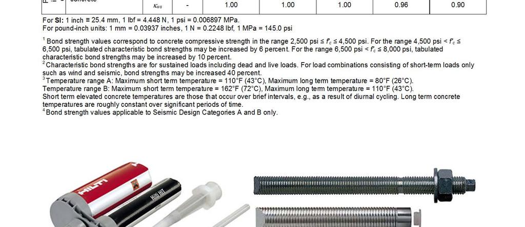
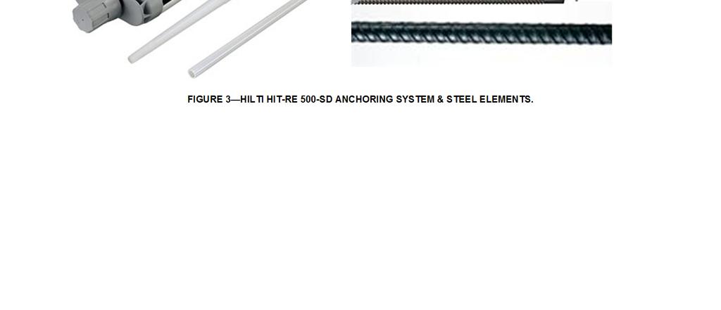
77
78 ESR-2322 Most Widely Accepted and Trusted Page 37 of 44 TABLE 35 ALLOWABLE STRESS DESIGN EXAMPLE Nominal anchor diameter Effective embedment depth f c k α Φ N n Allowable tension load φn n /α d o h ef (in.) (in.) (psi) (-) (-) (-) (lb) (lb) 3 / / 8 2, ,392 1,928 1 / / 4 2, ,472 2,403 5 / / 8 2, ,629 2,911 3 / / 2 2, ,857 3,450* 7 / / 2 2, ,840 3, , ,800 4, / 4 5 2, ,771 7,365 For SI: 1 lb = 4.45 kn, 1 psi = MPa, 1 in. = 25.4 mm Design Assumptions: 1. Single anchor with static tension load only; ASTM A 193 Grade B7 threaded rod 2. Vertical downward installation direction 3. Inspection Regimen = Periodic 4. Installation temperature = F 5. Long term temperature = 80 F 6. Short term temperature = 110 F 7. Dry hole condition carbide drilled hole 8. Embedment depth = h ef min 9. Concrete determined to remain uncracked for the life of the anchorage 10. Load combination from ACI 318 Section 9.2 (no seismic loading) % Dead Load (D) and 70% Live Load (L); Controlling load combination 1.2 D L 12. Calculation of α based on weighted average: α = 1.2 D L = 1.2 (0.30) (0.70) = Normal weight concrete: f c = 2,500 psi 14. Edge distance c a1 = c a2 > c ac 15. Member thickness h h min * Verify capacity Capacity ACI 318 Section Formula Calculation φ φn n Steel D.5.1 N sa = n A se, N f uta N sa = , ,360 lb Concrete D.5.2 N cb = k (f c ) h ef N cb = 24 (2,500) ,107 lb Bond D.5.3 a N a =π d h ef τ k, uncr N a = π 3/ , ,069 lb 5,107 lb ΦN n = 5,107 lb (concrete) is decisive hence the ASD value will be calculated as 1.48 = 3,450 lb a Design equation provided in Section Eq. (D-16f)
79 ESR-2322 Most Widely Accepted and Trusted Page 38 of 44 c a,min A 1/2-IN. A193 B7 ALL-THREAD N T max A A Na A Nc c cr,na d h ef h s/2 s/2 N s d d bit c cr,na c cr,na c a,min A-A Dimensional parameters: h ef = 9.0 in. s = 4.0 in. c a,min = 2.5 in. h = 12.0 in. d = 1 / 2 in. Specifications/assumptions: ASTM A193 Grade B7 all-thread rods, UNC thread, A 563 Grade HD hex nuts. Normal weight concrete, f c = 4,000 psi. Seismic Design Category (SDC) B No supplementary reinforcing in accordance with ACI D.1 will be provided. Assume maximum short term (diurnal) base material temperature 100 F. Assume maximum long term base material temperature 80 F. Assume installation in dry concrete and hammer-drilled holes. Assume concrete will remain uncracked for service life of anchorage. Calculation in accordance with ACI Appendix D and this report ACI 318 Code Ref. Report Ref. Step 1. Check minimum edge distance, anchor spacing and member thickness: - h ef,min < h ef therefore ok. Section 5.3 c min = 2.5 in. c a,min therefore ok. - Table 8 s min = 2.5 in. s therefore ok. - Table 8 h min = h ef = = in. h therefore ok. - Table 8 Step 2. Calculate steel strength: N = n A f D sa se uta ASTM A 193 Grade B7 rods comply as ductile. φ =075. D.1 and D.4.4a) - φn = φ n A f = , 000 = 26,606 lb = 26.6 k sa se uta or, using Table 7, φ N = , 737 = k Step 3. Determine concrete breakout strength: sa N A Nc cbg = ψ ec, N ψ ed, N ψ c, N ψ cp, N ANc0 N b D Table 7 D and Eq. (D-5) - A = ( 3 h + s)( 1.5 h + c ) = (27 + 4)( ) = 496 in Nc ef ef a,min A = h 2 = 729 in 2 D and Eq. (D-6) - Nc0 9 ef FIGURE 4 DESIGN EXAMPLE
80 ESR-2322 Most Widely Accepted and Trusted Page 39 of 44 Calculation in accordance with ACI Appendix D and this report ACI 318 Code Ref. Report Ref. ψ ec,n = 1.0 no eccentricity of tension load with respect to tension-loaded anchors D ca,min ψ ed,n = for ca,min 1.5 h 15. h c a, min ef D and ef Eq. (D-11) = 2.5 < ψ ed,n = = ψ c,n = 1.0 uncracked concrete assumed (k c,uncr = 24) D Table 8 Determine c ac : ( ) ( ). ( ) ef a,min = = 18 9 in. > 12.0 in. ac = 2.5 ef h c... c h c = in. = 22.5 in. ac For c a,min < c ac ψ cp,n 15. b c,uncr c ef max c a,min; 15. hef max 25; = = = 060. c ac ( ). 15 D Section D and Eq. (D-13) N = k f' h = 24 4, = 40, 983 lb D and Eq. (D-7) N cbg = ,983 = 12,715 lb φ N = , 715 = 8, 265 lb = 8.3 k D.4.4c) - cbg - - Step 4. Determine bond strength: N ag A Na = ed,na ψ g,na ψ ec,na ψ p,na ANa0 ψ N - a0 Section 4.1 Eq. (D-16b) S cr,na = min 20 3 d τ k,uncr ; 1,450 h 3 h = 27 in in. s = 12.4 in. ef cr,na ef = 2, ,450 = 12.4 in. scr.na ccr,na = = 6.2 in A = 2c + s c + c = in - A ( )( ) ( s ) 2 cr,na in Na cr,na cr,na a,min Na0 = = - c For ca,min < c : a,min cr.na ψ ed,na = c cr,na 2.5 ψ ed,na = = kc,uncr 24 τ = k,max,uncr hef f' c 9.0 4,000 2,899 psi π d = π 0.5 = k,uncr 2,235 Ψ g,na0 = n n 1 2 ( 2 1) τ k,max,uncr 2,899 = τ = - Section 4.1 Table 9 Section 4.1 Eq. (D-16e) Section 4.1 D Section 4.1 D Section Section Section 4.1 Table 8 Section 4.1 Table 9 FIGURE 4 DESIGN EXAMPLE (Continued)
81 ESR-2322 Most Widely Accepted and Trusted Page 40 of 44 Calculation in accordance with ACI Appendix D and this report ACI 318 Code Ref. Report Ref s 4.0 ψg,na = ψg,na0 + ( 1 ψg,na0 ) = ( ) = 1.06 s cr,na Section 4.1 ψ = 1.0 no eccentricity - loading is concentric - - ec,na max ca,min ; ccr,na max 2.5 ; 6.2 ψ p,na = = = c 22.5 N a0 = N ac τ k, uncr π d h ef = 2,235 π = 31,610 lb - A Na ag = ψ ed,na ψ g,na ψ ec,na ψ p,na ANa0 N ag N = ,610 = 7,134 lb a0 - Section 4.1 Eq. (D-16f) Section 4.1 Eq. (D-16h) φ = Table 9 φ N = ,134 = 4,637 lb = 4.6 k - ag Step 5. Determine controlling strength: D Steel strength φn sa = 26.6 k Concrete breakout strength φn cbg = 8.3 k Bond strength φn ag = 4.6 k controls Step 6. Convert strength to ASD using factor provided in Section 4.2: N N d φn n 4.6 = = = α α 1.48 ag = 3,108lb Note: For this example 30% dead load, 70% live load and a controlling load combination of 1.2D + 1.6L is assumed: α = 0.3* *1.6 = Section 4.2 FIGURE 4 SAMPLE CALCULATION (Continued)

82 ESR-2322 Most Widely Accepted and Trusted Page 41 of 44 FIGURE 5 INSTALLATION INSTRUCTIONS


83 ESR-2322 Most Widely Accepted and Trusted Page 42 of 44 FIGURE 5 INSTALLATION INSTRUCTIONS (Continued)


84 ESR-2322 Most Widely Accepted and Trusted Page 43 of 44 FIGURE 5 INSTALLATION INSTRUCTIONS (Continued)


85 ESR-2322 Most Widely Accepted and Trusted Page 44 of 44 FIGURE 5 INSTALLATION INSTRUCTIONS (Continued)
Hilti, Inc South 122 nd East Avenue Tulsa, OK
 Attached are page(s) from the 2011 Hilti North American Product Tech Guide. For complete details on this product, including data development, product specifications, general suitability, installation,
ESR-3574* Issued December 1, 2013 This report is subject to renewal August 1, 2014.
 ICC-ES Evaluation Report www.icc-es.org (800) 4-6587 (56) 699-054 ESR-574* Issued December, 0 This report is subject to renewal August, 04. A Subsidiary of the International Code Council DIVISION: 0 00
ICC-ES Evaluation Report Reissued April 1, 2011 This report is subject to renewal in two years.
 ICC-ES Evaluation Report www.icc-es.org (800) 4-6587 (56) 699-054 ESR-0 Reissued April, 0 This report is subject to renewal in two years. A Subsidiary of the International Code Council DIVISION: 0 00 00
ESR-2322 Issued November 1, 2007 This report is subject to re-examination in one year.
 ESR-3 Issued November, 007 This report is subject to re-examination in one year. ICC Evaluation Service, Inc. www.icc-es.org Business/Regional Office 5360 Workman Mill Road, Whittier, California 9060 (56)
*Revised September 2012
 ICC-ES Evaluation Report www.icc-es.org (800) 4-6587 (56) 699-054 ESR-6* Reissued July, 0 This report is subject to renewal August, 04. A Subsidiary of the International Code Council DIVISION: 0 00 00
DIVISION: CONCRETE SECTION: CONCRETE ANCHORS DIVISION: METALS SECTION: POST INSTALLED CONCRETE ANCHORS
 0 Most Widely Accepted and Trusted ICC ES Listing Report ICC ES 000 (800) 4 6587 (56) 699 054 www.icc es.org ELC 187 Issued May 018 This listing is subject to renewal May 019. DIVISION: 0 00 00 CONCRETE
DIVISION: CONCRETE SECTION: CONCRETE ANCHORS DIVISION: METALS SECTION: POST INSTALLED CONCRETE ANCHORS
 0 Most Widely Accepted and Trusted ICC ES Evaluation Report ICC ES 000 (800) 423 6587 (562) 699 0543 www.icc es.org ESR 3931 Reissued 07/2017 This report is subject to renewal 07/2019. DIVISION: 03 00
DIVISION: CONCRETE SECTION: CONCRETE ANCHORS DIVISION: METALS SECTION: POST INSTALLED CONCRETE ANCHORS
 0 Most Widely Accepted and Trusted ICC ES Evaluation Report ICC ES 000 (800) 423 6587 (562) 699 0543 www.icc es.org ESR 3576 Reissued 07/2017 This report is subject to renewal 07/2018. DIVISION: 03 00
DIVISION: CONCRETE SECTION: CONCRETE ANCHORS DIVISION: METALS SECTION: POST-INSTALLED CONCRETE ANCHORS
 0 Most Widely Accepted and Trusted ICC-ES Report ICC-ES 000 (800) 423-6587 (562) 699-0543 www.icc-es.org ESR-3930 Issued 4/2017 This report is subject to renewal 2/2018. DIVISION: 03 00 00 CONCRETE SECTION:
DIVISION: MASONRY SECTION: MASONRY ANCHORS REPORT HOLDER: HILTI, INC DALLAS PARKWAY, SUITE 1000 PLANO, TEXAS 75024
 0 Most Widely Accepted and Trusted ICC ES Evaluation Report ICC ES 000 (800) 423 587 (52) 99 0543 www.icc es.org ESR 393 Reissued 12/2017 This report is subject to renewal 12/2018. DIVISION: 04 00 00 MASONRY
DIVISION: CONCRETE SECTION: CONCRETE ANCHORS DIVISION: METALS SECTION: POST INSTALLED CONCRETE ANCHORS
 0 Most Widely Accepted and Trusted ICC ES Evaluation Report ICC ES 000 (800) 423 6587 (562) 699 0543 www.icc es.org ESR 3959 Reissued 08/2018 This report is subject to renewal 08/2020. DIVISION: 03 00
CITY OF LOS ANGELES CALIFORNIA
 BOARD OF BUILDING AND SAFETY COMMISSIONERS MARSHA L. BROWN PRESIDENT VAN AMBATIELOS VICE-PRESIDENT VICTOR H. CUEVAS HELENA JUBANY ELENORE A. WILLIAMS CITY OF LOS ANGELES CALIFORNIA ANTONIO R. VILLARAIGOSA
DIVISION: CONCRETE SECTION: CONCRETE ANCHORS DIVISION: METALS SECTION: POST-INSTALLED CONCRETE ANCHORS
 0 Most Widely Accepted and Trusted ICC-ES Listing Report ICC-ES 000 (800) 423-6587 (562) 699-0543 www.icc-es.org ELC-4027 Issued 07/2017 This listing is subject to renewal 07/2018. DIVION: 03 00 00 CONCRETE
DIVISION: CONCRETE SECTION: CONCRETE ANCHORS DIVISION: METALS SECTION: POST INSTALLED CONCRETE ANCHORS
 0 ICC ES Report ICC ES (800) 42 6587 (562) 699 054 www.icc es.org 000 Most Widely Accepted and Trusted ESR 608 Valid: 08/4 to 08/5 DIVISION: 0 00 00 CONCRETE SECTION: 0 6 00 CONCRETE ANCHORS DIVISION:
DIVISION: CONCRETE SECTION: CONCRETE ANCHORS DIVISION: METALS SECTION: POST-INSTALLED CONCRETE ANCHORS
 0 Most Widely Accepted and Trusted ICC-ES Listing Report ICC-ES 000 (800) 423-6587 (562) 699-0543 www.icc-es.org ELC-4027 Issued 07/2017 This listing is subject to renewal 07/2018. DIVISION: 03 00 00 CONCRETE
DIVISION: CONCRETE SECTION: CONCRETE ANCHORS DIVISION: METALS SECTION: POST INSTALLED CONCRETE ANCHORS
 0 Most Widely Accepted and Trusted ICC ES Evaluation Report ICC ES 000 (800) 42 6587 (562) 699 054 www.icc es.org ESR 608 Reissued 08/207 This report is subject to renewal 08/208. DIVISION: 0 00 00 CONCRETE
DIVISION: CONCRETE SECTION: CONCRETE ANCHORS DIVISION: METALS SECTION: POST-INSTALLED CONCRETE ANCHORS
 0 Most Widely Accepted and Trusted ICC-ES Evaluation Report ICC-ES 000 (800) 43-6587 (56) 699-0543 www.icc-es.org ESR-384 Reissued 0/07 This report is subject to renewal 0/09. DIVISION: 03 00 00 CONCRETE
DIVISION: CONCRETE SECTION: CONCRETE ANCHORS DIVISION: METALS SECTION: POST INSTALLED CONCRETE ANCHORS
 0 Most Widely Accepted and Trusted ICC ES Evaluation Report ICC ES 000 (800) 423 6587 (562) 699 0543 www.icc es.org ESR 3608 Reissued 08/2018 This report is subject to renewal 08/2019. DIVISION: 03 00
DIVISION: CONCRETE SECTION: CONCRETE ANCHORS DIVISION: METALS SECTION: POST INSTALLED CONCRETE ANCHORS
 0 Most Widely Accepted and Trusted ICC ES Report ICC ES 000 (800) 423 6587 (562) 699 0543 www.icc es.org ESR 3572 Reissued 04/207 This report is subject to renewal 04/209. DIVISION: 03 00 00 CONCRETE SECTION:
DIVISION: CONCRETE SECTION: CONCRETE ANCHORS DIVISION: METALS SECTION: POST-INSTALLED CONCRETE ANCHORS
 0 ICC-ES Evaluation Report ICC-ES 000 (800) 423-6587 (562) 699-0543 www.icc-es.org Most Widely Accepted and Trusted ESR-2583 Reissued 12/2018 This report is subject to renewal 12/2019.. DIVISION: 03 00
1 True Epoxy. Product Submittal/Substitution Request TO: PROJECT: PROJECT LOCATION: SPECIFIED ITEM: Section Page Paragraph Description
 Product Submittal/Substitution Request TE + 1 True Epoxy TO: PROJECT: PROJECT LOCATION: SPECIFIED ITEM: Section Page Paragraph Description FOR USE BY THE ARCHITECT AND/OR ENGINEER Approved Approved as
DIVISION: CONCRETE SECTION: CONCRETE ANCHORS DIVISION: METALS SECTION: POST-INSTALLED CONCRETE ANCHORS
 0 ICC-ES Report ICC-ES (800) 423-6587 (562) 699-0543 www.icc-es.org 000 Most Widely Accepted and Trusted ESR-2538 Reissued 05/2016 This report is subject to renewal 05/2018. DIVISION: 03 00 00 CONCRETE
DIVISION: CONCRETE SECTION: CONCRETE ANCHORS DIVISION: METALS SECTION: POST-INSTALLED CONCRETE ANCHORS
 0 Most Widely Accepted and Trusted ICC-ES Evaluation Report ICC-ES 000 (800) 423-6587 (562) 699-0543 www.icc-es.org ESR-1990 Reissued 09/2017 This report is subject to renewal 09/2019. DIVISION: 03 00
DIVISION: CONCRETE SECTION: CONCRETE ANCHORS DIVISION: METALS SECTION: POST INSTALLED CONCRETE ANCHORS
 0 ICC ES Evaluation Report ICC ES 000 (800) 423 6587 (562) 699 0543 www.icc es.org Most Widely Accepted and Trusted ESR 3576 Reissued 07/2018 Revised 11/2018 This report is subject to renewal 07/2019.
DIVISION: CONCRETE SECTION: CONCRETE ANCHORS DIVISION: METALS SECTION: POST INSTALLED CONCRETE ANCHORS
 0 Most Widely Accepted and Trusted ICC ES Evaluation Report ICC ES 000 (800) 423 6587 (562) 699 0543 www.icc es.org ESR 2582 Reissued 02/2018 This report is subject to renewal 02/2019. DIVISION: 03 00
DIVISION: CONCRETE SECTION: CONCRETE ANCHORS DIVISION: METALS SECTION: POST INSTALLED CONCRETE ANCHORS
 0 Most Widely Accepted and Trusted ICC ES Evaluation Report ICC ES 000 (800) 423 6587 (562) 699 0543 www.icc es.org ESR 2254 Reissued 12/2017 This report is subject to renewal 12/2019. DIVISION: 03 00
Trusted SECTION: SECTION: 05 GERMANYY. Issued 4/2015. Conformity! Copyright ICC-ES Evaluation. not specifically
 0 ICC ES Report ICC ES (800) 423 6587 (562) 699 0543 www.icc es.orgg 000 Most Widely Accepted and Trusted KLAUS FISCHER STRASSE 1 72178 WALDACHTAL GERMANYY EVALUATION SUBJECT: ESR 3572 Issued 4/2015 This
DIVISION: CONCRETE SECTION: CONCRETE ANCHORS DIVISION: METALS SECTION: POST-INSTALLED CONCRETE ANCHORS
 0 Most Widely Accepted and Trusted ICC-ES Evaluation Report ICC-ES 000 (800) 43-6587 (56) 699-0543 www.icc-es.org ESR-384 Reissued 0/07 This report is subject to renewal 0/09. DIVISION: 03 00 00 CONCRETE
DIVISION: CONCRETE SECTION: CONCRETE ANCHORS DIVISION: METALS SECTION: POST-INSTALLED CONCRETE ANCHORS
 0 Most Widely Accepted and Trusted ICC-ES Evaluation Report ICC-ES 000 (800) 423-6587 (562) 699-0543 www.icc-es.org ESR-4151 Issued 08/2017 This report is subject to renewal 04/2019. DIVISION: 03 00 00
ESR-3122 Issued May 1, 2010 This report is subject to re-examination in one year.
 ICC-ES Evaluation Report ESR-3122 Issued May 1, 2010 This report is subject to re-examination in one year. www.icc-es.org (800) 423-6587 (562) 699-0543 A Subsidiary of the International Code Council DIVISION:
DIVISION: CONCRETE SECTION: CONCRETE ANCHORS DIVISION: METALS SECTION: POST INTALLED CONCRETE ANCHORS
 0 Most Widely Accepted and Trusted ICC ES Evaluation Report ICC ES 000 (800) 423 6587 (562) 699 0543 www.icc es.org ESR 3372 Reissued 09/2017 This report is subject to renewal 09/2018. DIVISION: 03 00
DIVISION: CONCRETE SECTION: CONCRETE ANCHORS DIVISION: METALS SECTION: POST INSTALLED CONCRETE ANCHORS
 0 Most Widely Accepted and Trusted ICC ES Evaluation Report ICC ES 000 (800) 423 6587 (562) 699 0543 www.icc es.org ESR 3187 Reissued 03/2018 This report is subject to renewal 03/2020. DIVISION: 03 00
ESR ICC Evaluation Service, Inc. Reissued January 1, 2008 This report is subject to re-examination in one year.
 ESR-1967 Reissued January 1, 2008 This report is subject to re-examination in one year. ICC Evaluation Service, Inc. www.icc-es.org Business/Regional Office # 5360 Workman Mill Road, Whittier, California
DIVISION: CONCRETE SECTION: CONCRETE ANCHORS DIVISION: METALS SECTION: POST INSTALLED CONCRETE ANCHORS
 0 Most Widely Accepted and Trusted ICC ES Report ICC ES 000 (800) 423 6587 (562) 699 0543 www.icc es.org ESR 4004 Issued 02/2017 This report is subject to renewal 02/2019. DIVISION: 03 00 00 CONCRETE SECTION:
DIVISION: MASONRY SECTION: MASONRY ANCHORS REPORT HOLDER: HILTI, INC DALLAS PARKWAY, SUITE 1000 PLANO, TEXAS 75024
 0 Most Widely Accepted and Trusted ICC-ES Evaluation Report ICC-ES 000 (800) 423-6587 (562) 699-0543 www.icc-es.org ESR-4143 Issued 01/2018 This report is subject to renewal 01/2019. DIVISION: 04 00 00
DIVISION: CONCRETE SECTION: CONCRETE ANCHORS DIVISION: METALS SECTION: POST INSTALLED CONCRETE ANCHORS
 0 Most Widely Accepted and Trusted ICC ES Report ICC ES 000 (800) 423 6587 (562) 699 0543 www.icc es.org ESR 3852 Reissued 03/2017 This report is subject to renewal 03/2018. DIVISION: 03 00 00 CONCRETE
DIVISION: CONCRETE SECTION: CONCRETE ANCHORS DIVISION: METALS SECTION: POST INSTALLED CONCRETE ANCHORS
 0 Most Widely Accepted and Trusted ICC ES Evaluation Report ICC ES 000 (800) 423 6587 (562) 699 0543 www.icc es.org ESR 4252 Issued June 2018 This report is subject to renewal June 2019 DIVISION: 03 00
DIVISION: MASONRY SECTION: MASONRY ANCHORS REPORT HOLDER: HILTI, INC SOUTH 122 ND EAST AVENUE TULSA, OKLAHOMA 74146
 0 ICC ES Report ICC ES (800) 42 87 (2) 99 04 www.icc es.org 000 Most Widely Accepted and Trusted ESR 282 Valid: 08/4 to 08/ DIVISION: 04 00 00 MASONRY SECTION: 04 0 9. MASONRY ANCHORS REPORT HOLDER: HILTI,
DIVISION: CONCRETE SECTION: CONCRETE ANCHORS DIVISION: METALS SECTION: POST INSTALLED CONCRETE ANCHORS
 0 Most Widely Accepted and Trusted ICC ES Evaluation Report ICC ES 000 (800) 423 6587 (562) 699 0543 www.icc es.org ESR 4264 Issued June 2018 This report is subject to renewal June 2019. DIVISION: 03 00
ESR-2202 Issued May 1, 2009 This report is subject to re-examination in one year.
 ICC-ES Evaluation Report ESR-2202 Issued May, 2009 This report is subject to re-examination in one year. www.icc-es.org (800) 42-6587 (562) 699-054 A Subsidiary of the International Code Council DIVISION:
DIVISION: CONCRETE SECTION: CONCRETE ANCHORS DIVISION: METALS SECTION: POST INTALLED CONCRETE ANCHORS
 0 Most Widely Accepted and Trusted ICC ES Evaluation Report ICC ES 000 (00) 42 7 (2) 99 04 www.icc es.org ESR 20 Reissued 11/2017 This report is subject to renewal 11/201. DIVISION: 0 00 00 CONCRETE SECTION:
ICC-ES Evaluation Report. ESR-3342 Reissued July 1, 2013 This report is subject to renewal August 1, 2015.
 ICC-ES Evaluation Report www.icc-es.org (800) 423-6587 (562) 699-0543 ESR-3342 Reissued July 1, 2013 This report is subject to renewal August 1, 2015. A Subsidiary of the International Code Council DIVISION:
DIVISION: CONCRETE SECTION: CONCRETE ANCHORS DIVISION: METALS SECTION: POST-INSTALLED CONCRETE ANCHORS
 0 Most Widely Accepted and Trusted ICC-ES Evaluation Report ICC-ES 000 (800) 423-6587 (562) 699-0543 www.icc-es.org ESR-4000 Reissued 09/2017 This report is subject to renewal 08/2019. DIVISION: 03 00
DIVISION: CONCRETE SECTION: CONCRETE ANCHORS DIVISION: METALS SECTION: POST INSTALLED CONCRETE ANCHORS
 0 Most Widely Accepted and Trusted ICC ES Evaluation Report ICC ES 000 (800) 423 6587 (562) 699 0543 www.icc es.org ESR 4057 Issued 04/208 This report is subject to renewal 04/209. DIVISION: 03 00 00 CONCRETE
DIVISION: CONCRETE SECTION: CAST-IN CONCRETE ANCHORS SECTION: CONCRETE ANCHORS REPORT HOLDER: HILTI, INC.
 0 Most Widely Accepted and Trusted ICC-ES Evaluation Report ICC-ES 000 (800) 423-6587 (562) 699-0543 www.icc-es.org ESR-4145 Issued 02/2018 This report is subject to renewal 02/2019. DIVISION: 03 00 00
DIVISION: CONCRETE SECTION: CONCRETE ANCHORS DIVISION: METALS SECTION: POST INSTALLED CONCRETE ANCHORS
 0 Most Widely Accepted and Trusted ICC ES Evaluation Report ICC ES 000 (800) 2 687 (62) 699 0 www.icc es.org ESR 067 Reissued 06/208 This report is subject to renewal 06/209. DIVISION: 0 00 00 CONCRETE
To: Firm: Project: Product Specified: Specified Location:
 Submittal Substitution Request To: Firm: Project: Product Specified: Specified Location: Attached information includes product description, installation instructions and technical data needed for review
DIVISION: CONCRETE SECTION: CONCRETE ANCHORS DIVISION: METALS SECTION: POST-INSTALLED CONCRETE ANCHORS
 0 Most Widely Accepted and Trusted ICC-ES Evaluation Report ICC-ES 000 (800) 423-6587 (562) 699-0543 www.icc-es.org ESR-3932 Reissued 07/2017 This report is subject to renewal 07/2018. DIVISION: 03 00
ESR-2713 Reissued August 1, 2013 This report is subject to renewal September 1, 2014.
 ICC-ES Evaluation Report www.icc-es.org (800) 42-8 (2) 99-04 ESR-2 Reissued August, 20 This report is subject to renewal September, 204. A Subsidiary of the International Code Council DIVISION: 0 00 00
DIVISION: MASONRY SECTION: MASONRY ANCHORS REPORT HOLDER: DEWALT
 0 ICC-ES Evaluation Report ICC-ES 000 (800) 423-6587 (562) 699-0543 www.icc-es.org Most Widely Accepted and Trusted ESR-3200 Reissued 12/2017 Revised 10/2018 This report is subject to renewal 12/2018 DIVISION:
DIVISION: CONCRETE SECTION: CONCRETE ANCHORS DIVISION: METALS SECTION: POST-INSTALLED CONCRETE ANCHORS
 0 ICC-ES Evaluation Report ICC-ES 000 (800) 423-6587 (562) 699-0543 www.icc-es.org Most Widely Accepted and Trusted ESR-4027 Reissued 01/2018 Revised 08/2018 This report is subject to renewal 01/2020.
DIVISION: CONCRETE SECTION: CAST IN CONCRETE ANCHORS SECTION: CONCRETE ANCHORS REPORT HOLDER: DEWALT
 0 Most Widely Accepted and Trusted ICC ES Evaluation Report ICC ES 000 (800) 423 6587 (562) 699 0543 www.icc es.org ESR 3657 Reissued 12/2017 This report is subject to renewal 12/2018. DIVISION: 03 00
Trusted ICC ES HILTI, INC. SYSTEM E ANCHOR. Conformity! Look. Evaluation. ICC-ES Evaluation
 0 Most Widely Accepted and Trusted ICC ES Evaluation Report ICC ES 000 (800) 423 6587 (562) 699 0543 www.icc es.orgg ESR 2682 Reissued 08/2016 This report is subject to renewal 08/2018. DIVISION: 04 00
DIVISION: MASONRY SECTION: MASONRY ANCHORS REPORT HOLDER: DEWALT 701 EAST JOPPA ROAD TOWSON, MARYLAND EVALUATION SUBJECT:
 0 Most Widely Accepted and Trusted ICC ES Evaluation Report ICC ES 000 (800) 423 6587 (562) 699 0543 www.icc es.org ESR 3200 Reissued 12/2017 This report is subject to renewal 12/2018. DIVISION: 04 00
DIVISION: CONCRETE SECTION: CAST IN CONCRETE ANCHORS DIVISION: CONCRETE ANCHORS REPORT HOLDER: DEWALT
 0 Most Widely Accepted and Trusted ICC ES Listing Report ICC ES 000 (800) 423 6587 (562) 699 0543 www.icc es.org ELC 3657 Issued 05/2017 This listing is subject to renewal 05/2018. DIVISION: 03 00 00 CONCRETE
DIVISION: CONCRETE SECTION: CONCRETE ANCHORS DIVISION: METALS SECTION: POST INSTALLED CONCRETE ANCHORS
 0 Most Widely Accepted and Trusted ICC ES Evaluation Report ICC ES 000 (800) 423 6587 (562) 699 0543 www.icc es.org ESR 2272 Reissued 12/2017 This report is subject to renewal 12/2018. DIVISION: 03 00
DIVISION: CONCRETE SECTION: CONCRETE ANCHORS DIVISION: METALS SECTION: POST INSTALLED CONCRETE ANCHORS
 0 ICC ES Report ICC ES (00) 7 () 0 www.icc es.org 000 Most Widely Accepted and Trusted ESR 70 Reissued 0/0 This report is subject to renewal 0/0. DIVISION: 0 00 00 CONCRETE SECTION: 0 00 CONCRETE ANCHORS
DIVISION: CONCRETE SECTION: CONCRETE ANCHORS DIVISION: METALS SECTION: POST INSTALLED CONCRETE ANCHORS
 0 Most Widely Accepted and Trusted ICC ES Evaluation Report ICC ES 000 (800) 423 6587 (562) 699 0543 www.icc es.org ESR 4138 Issued 09/2017 This report is subject to renewal 09/2018. DIVISION: 03 00 00
DIVISION: MASONRY SECTION: MASONRY ANCHORS REPORT HOLDER: HILTI, INC DALLAS PARKWAY, SUITE 1000 PLANO, TEXAS 75024
 0 Most Widely Accepted and Trusted ICC-ES Evaluation Report ICC-ES 000 (800) 423-6587 (562) 699-0543 www.icc-es.org ESR-3342 Reissued 08/2017 This report is subject to renewal 08/2018. DIVISION: 04 00
DIVISION: MASONRY SECTION: MASONRY ANCHORS REPORT HOLDER: HILTI, INC. EVALUATION SUBJECT: KWIK BOLT TZ MASONRY ANCHORS
 0 Most Widely Accepted and Trusted ICC ES Evaluation Report ICC ES 000 (800) 4 687 (6) 699 04 www.icc es.org ESR 78 Reissued 07/018 This report is subject to renewal 07/019. DIVISION: 04 00 00 MASONRY
DIVISION: MASONRY SECTION: MASONRY ANCHORS REPORT HOLDER: HILTI, INC DALLAS PARKWAY, SUITE 1000 PLANO, TEXAS 75024
 0 Most Widely Accepted and Trusted ICC ES Evaluation Report ICC ES 000 (800) 687 (6) 699 0 www.icc es.org ESR 8 Reissued 0/08 This report is subject to renewal 0/09. DIVISION: 0 00 00 MASONRY SECTION:
The following excerpt are pages from the North American Product Technical Guide, Volume 2: Anchor Fastening, Edition 16.
 The following excerpt are pages from the North American Product Technical Guide, Volume 2: Anchor Fastening, Edition 16. Please refer to the publication in its entirety for complete details on this product
DIVISION: MASONRY SECTION: MASONRY ANCHORS REPORT HOLDER: DEWALT 701 EAST JOPPA ROAD TOWSON, MARYLAND EVALUATION SUBJECT:
 0 Most Widely Accepted and Trusted ICC ES Evaluation Report ICC ES 000 (800) 423 6587 (562) 699 0543 www.icc es.org ESR 2966 Reissued 12/2017 This report is subject to renewal 12/2018. DIVISION: 04 00
DIVISION: CONCRETE SECTION: CONCRETE ANCHORS DIVISION: METALS SECTION: POST INSTALLED CONCRETE ANCHORS
 0 Most Widely Accepted and Trusted ICC ES Evaluation Rept ICC ES 000 (800) 423 6587 (562) 699 0543 www.icc es.g ESR 3411 Reissued 07/2018 This rept is subject to renewal 05/2019. DIVISION: 03 00 00 CONCRETE
DIVISION: MASONRY SECTION: MASONRY ANCHORS REPORT HOLDER: DEWALT 701 EAST JOPPA ROAD TOWSON, MARYLAND EVALUATION SUBJECT:
 0 Most Widely Accepted and Trusted ICC ES Report ICC ES 000 (800) 423 6587 (562) 699 0543 www.icc es.org ESR 2966 Reissued 12/2016 This report is subject to renewal 12/2017. DIVISION: 04 00 00 MASONRY
DIVISION: CONCRETE SECTION: CONCRETE ANCHORS DIVISION: METALS SECTION: POST INSTALLED CONCRETE ANCHORS
 0 Most Widely Accepted and Trusted ICC ES Evaluation Report ICC ES 000 (800) 423 6587 (562) 699 0543 www.icc es.org ESR 3772 Reissued 10/2017 This report is subject to renewal 10/2019. DIVISION: 03 00
DIVISION: MASONRY SECTION: MASONRY ANCHORS REPORT HOLDER: HILTI, INC DALLAS PARKWAY, SUITE 1000 PLANO, TEXAS 75024
 0 Most Widely Accepted and Trusted ICC ES Report ICC ES 000 (800) 423 6587 (562) 699 0543 www.icc es.org ESR 3056 Reissued 10/2015 This report is subject to renewal 10/2017. DIVISION: 04 00 00 MASONRY
DIVISION: CONCRETE SECTION: CONCRETE ANCHORS DIVISION: METALS SECTION: POST INSTALLED CONCRETE ANCHORS
 0 Most Widely Accepted and Trusted ICC ES Evaluation Report ICC ES 000 (800) 423 6587 (562) 699 0543 www.icc es.org ESR 3251 Reissued 11/2017 This report is subject to renewal 11/2018. DIVISION: 03 00
DIVISION: MASONRY SECTION: MASONRY ANCHORS REPORT HOLDER: HILTI, INC DALLAS PARKWAY, SUITE 1000 PLANO, TEXAS 75024
 0 Most Widely Accepted and Trusted ICC ES Evaluation Report ICC ES 000 (800) 42 687 (62) 699 04 www.icc es.org ESR 06 Reissued 0/207 This report is subject to renewal 0/208. DIVISION: 04 00 00 MASONRY
DIVISION: CONCRETE SECTION: CONCRETE ANCHORS DIVISION: METALS SECTION: POST INSTALLED CONCRETE ANCHORS
 0 Most Widely Accepted and Trusted ICC ES Evaluation Report ICC ES 000 (800) 423 6587 (562) 699 0543 www.icc es.org ESR 3068 Reissued 07/2018 This report is subject to renewal 07/2019. DIVISION: 03 00
DIVISION: CONCRETE SECTION: CONCRETE ANCHORS DIVISION: METALS SECTION: POST INSTALLED CONCRETE ANCHORS
 0 Most Widely Accepted and Trusted ICC ES Listing Report ICC ES 000 (800) 423 6587 (562) 699 0543 www.icc es.org ESL 1067 Reissued 09/2017 This listing is subject to renewal 09/2018. DIVISION: 03 00 00
DIVISION: MASONRY SECTION: MASONRY ANCHORS REPORT HOLDER: DEWALT 701 EAST JOPPA ROAD TOWSON, MARYLAND EVALUATION SUBJECT:
 0 Most Widely Accepted and Trusted ICC ES Report ICC ES 000 (800) 423 6587 (562) 699 0543 www.icc es.org ESR 1678 Reissued 03/2017 This report is subject to renewal 03/2018. DIVISION: 04 00 00 MASONRY
DIVISION: CONCRETE SECTION: CONCRETE ANCHORS DIVISION: METALS SECTION: POST-INSTALLED CONCRETE ANCHORS
 0 Most Widely Accepted and Trusted ICC-ES Evaluation Report ICC-ES 000 (800) 423-6587 (562) 699-0543 www.icc-es.org ESR-3981 Issued 10/2017 This report is subject to renewal 10/2018. DIVISION: 03 00 00
DIVISION: CONCRETE SECTION: CAST IN CONCRETE ANCHORS SECTION: CONCRETE ANCHORS REPORT HOLDER: MASON WEST, INC.
 0 Most Widely Accepted and Trusted ICC ES Evaluation Report ICC ES 000 (800) 423 6587 (562) 699 0543 www.icc es.org ESR 3443 Issued 04/2017 This report is subject to renewal 04/2018. DIVISION: 03 00 00
ICC-ES Evaluation Report. ESR-3707 Issued October 2014 This report is subject to renewal November 2015.
 4 ICC-ES Evaluation Report www.icc-es.org (800) 42-687 (62) 699-04 ESR-707 Issued October 2014 This report is subject to renewal November 201. A Subsidiary of the International Code Council DIVISION: 0
Fast Cure Anchoring Adhesive
 ESR-4249 Product Description ULTRABOND ACRYL-8CC is a two-component (10:1 mix ratio by volume), high strength, styrene-free, vinylester adhesive anchoring system tested for use with threaded rod and reinforcing
DIVISION: CONCRETE SECTION: CONCRETE ANCHORS DIVISION: METALS SECTION: POST INSTALLED CONCRETE ANCHORS
 0 Most Widely Accepted and Trusted ICC ES Evaluation Report ICC ES 000 (800) 423 6587 (562) 699 0543 www.icc es.org ESR 3173 Reissued 12/2018 This report is subject to renewal 12/2020. DIVISION: 03 00
DIVISION: CONCRETE SECTION: CAST-IN CONCRETE ANCHORS SECTION: CONCRETE ANCHORS REPORT HOLDER:
 0 Most Widely Accepted and Trusted ICC-ES Evaluation Report ICC-ES 000 (800) 423-6587 (562) 699-0543 www.icc-es.org ESR-3864 Reissued 05/2018 This report is subject to renewal 05/2019. DIVISION: 03 00
The ONLY Fast Cure ICC-ES Listed Adhesive for Water-filled Holes and Submerged Concrete
 ADHESIVE ANCHORING SPECIALISTS DESCRIPTION Fast Curing The ONLY Fast Cure ICC-ES Listed Adhesive for Water-filled Holes and Submerged Concrete The resin and hardening agent are completely mixed as they
DIVISION: CONCRETE SECTION: CONCRETE ANCHORS DIVISION: METALS SECTION: POST-INSTALLED CONCRETE ANCHORS
 0 Most Widely Accepted and Trusted ICC-ES Evaluation Rept ICC-ES 000 (800) 423-6587 (562) 699-0543 www.icc-es.g ESR-3853 Reissued 05/2016 This rept is subject to renewal 05/2018. DIVISION: 03 00 00 CONCRETE
ICC-ES Evaluation Report
 ICC-ES Evaluation Report www.icc-es.org (800) 423-6587 (562) 699-0543 ESR-2427 Reissued November 1, 2010 This report is subject to re-examination in one year. A Subsidiary of the International Code Council
Hilti, Inc South 122 nd East Avenue Tulsa, OK
 Attached are page(s) from the 2011 Hilti North American Product Tech Guide. For complete details on this product, including data development, product specifications, general suitability, installation,
DIVISION: MASONRY SECTION: MASONRY ANCHORS REPORT HOLDER: POWERS FASTENERS, INC. 701 EAST JOPPA ROAD TOWSON, MARYLAND 21286
 0 ICC-ES Report ICC-ES (800) -687 (6) 6-0 www.icc-es.org 000 Most Widely Accepted and Trusted ESR-678 Reissued 0/0 This report is subject to renewal 0/06 DIVISION: 0 00 00 MASONRY SECTION: 0 0.6 MASONRY
DIVISION: CONCRETE SECTION: CONCRETE ANCHORS DIVISION: METALS SECTION: POST-INSTALLED CONCRETE ANCHORS
 0 ICC-ES Report ICC-ES (800) 423-6587 (562) 699-0543 www.icc-es.org 000 Most Widely Accepted and Trusted ESR-1546 Reissued 03/2016 This report is subject to renewal 03/2018. DIVISION: 03 00 00 CONCRETE
SET-3G High-Strength Epoxy Adhesive. Adhesive Anchors. Cracked. Concrete CODE LISTED. Features. SET-3G Adhesive. Applications
 SET-3G High-Strength Epoxy Adhesive SET-3G is the latest innovation in epoxy anchoring adhesives from Simpson Strong-Tie. Formulated to provide superior performance in cracked and uncracked concrete at
DIVISION: CONCRETE SECTION: CONCRETE ANCHORS DIVISION: METALS SECTION: POST-INSTALLED CONCRETE ANCHORS
 0 ICC-ES Report ICC-ES (800) 43-6587 (56) 699-0543 www.icc-es.org 000 Most Widely Accepted and Trusted ESR-1917 Reissued 05/015 This report is subject to renewal 05/017. DIVISION: 03 00 00 CONCRETE SECTION:
DIVISION: MASONRY SECTION: MASONRY ANCHORS REPORT HOLDER: MITEK USA, INC.
 0 Most Widely Accepted and Trusted ICC-ES Evaluation Report ICC-ES 000 (800) 423-6587 (562) 699-0543 www.icc-es.org ESR-1702 Reissued 06/2016 This report is subject to renewal 06/2018. DIVISION: 04 00
DIVISION: CONCRETE SECTION: CONCRETE ANCHORS DIVISION: METALS SECTION: POST INSTALLED CONCRETE ANCHORS
 0 Most Widely Accepted and Trusted ICC ES Listing Report ICC ES 000 (800) 423 6587 (562) 699 0543 www.icc es.org ELC 1917 Reissued 9/2017 This listing is subject to renewal 9/2018. DIVISION: 03 00 00 CONCRETE
DIVISION: CONCRETE SECTION: CONCRETE ANCHORS DIVISION: METALS SECTION: POST INSTALLED CONCRETE ANCHORS
 0 Most Widely Accepted and Trusted ICC ES Evaluation Report ICC ES 000 (800) 42 6587 (562) 699 054 www.icc es.org ESR 027 Reissued 2/207 This report is subject to renewal 2/209. DIVISION: 0 00 00 CONCRETE
ICC-ES Evaluation Report Reissued March 2014 This report is subject to renewal May 1, 2015
 [Type text] ICC-ES Evaluation Report www.icc-es.org (800) 423-6587 (562) 699-0543 ESR-1958 Reissued March 2014 This report is subject to renewal May 1, 2015 A Subsidiary of the International Code Council
ESR-1545 Reissued February 1, 2014 This report is subject to renewal March 1, 2016.
 ICC-ES Evaluation Report ESR-1545 Reissued February 1, 014 This report is subject to renewal March 1, 016. www.icc-es.org (800) 43-6587 (56) 699-0543 A Subsidiary of the International Code Council DIVISION:
*Corrected October 2005
 ESR-1056* Reissued December 1, 2004 This report is subject to re-examination in two years. ICC Evaluation Service, Inc. www.icc-es.org Business/Regional Office # 5360 Workman Mill Road, Whittier, California
DIVISION: MASONRY SECTION: MASONRY ANCHORS REPORT HOLDER: DEWALT 701 EAST JOPPA ROAD TOWSON, MARYLAND EVALUATION SUBJECT:
 0 Most Widely Accepted and Trusted ICC ES Evaluation Report ICC ES 000 (800) 423 6587 (562) 699 0543 www.icc es.org ESR 4042 Issued 07/2017 This report is subject to renewal 07/2018. DIVISION: 04 00 00
DIVISION: CONCRETE SECTION: CAST IN CONCRETE ANCHORS SECTION: CONCRETE ANCHORS REPORT HOLDER: HILTI, INC.
 0 Most Widely Accepted and Trusted ICC ES Evaluation Report ICC ES 000 (800) 423 6587 (562) 699 0543 www.icc es.org ESR 4006 Reissued 11/2017 This report is subject to renewal 11/2019. DIVISION: 03 00
DIVISION: MASONRY SECTION: MASONRY ANCHORS REPORT HOLDER: 5956 WEST LAS POSITAS BOULEVARD PLEASANTON, CALIFORNIA 94588
 0 ICC ES Report ICC ES (800) 4 687 (6) 699 04 www.icc es.org 000 Most Widely Accepted and Trusted ESR 06 Valid: 0/ to 0/6 DIVISION: 04 00 00 MASONRY SECTION: 04 0 9.6 MASONRY ANCHORS REPORT HOLDER: SIMPSON
Legacy report on the 1997 Uniform Building Code, the 2000 International Building Code and the 2000 International Residential Code.
 LEGACY REPORT ER-2895 Reissued March 1, 2004 www.icc-es.org Business/Regional Office 5360 Workman Mill Road, Whittier, California 90601 (562) 699-0543 Regional Office 900 Montclair Road, Suite A, Birmingham,
DIVISION: MASONRY SECTION: MASONRY ANCHORS REPORT HOLDER: DEWALT 701 EAST JOPPA TOWSON, MARYLAND EVALUATION SUBJECT:
 0 Most Widely Accepted and Trusted ICC ES Evaluation Report ICC ES 000 (800) 423 6587 (562) 699 0543 www.icc es.org ESR 4105 Issued 08/2017 This report is subject to renewal 08/2018. DIVISION: 04 00 00
DIVISION: CONCRETE SECTION: CAST IN CONCRETE ANCHORS SECTION: CONCRETE ANCHORS REPORT HOLDER: HILTI, INC.
 0 Most Widely Accepted and Trusted ICC ES Report ICC ES 000 (800) 423 6587 (562) 699 0543 www.icc es.org ESR 3713 Reissued 07/2016 This report is subject to renewal 07/2018. DIVISION: 03 00 00 CONCRETE
Originally Issued: 11/14/2012 Revised: 11/29/2017 Valid Through: 11/30/2018
 EVALUATION SUBJECT: AT-XP ADHESIVE ANCHORS FOR CRACKED AND UNCRACKED CONCRETE REPORT HOLDER: Simpson Strong-Tie Company Inc. 5956 West Las Positas Boulevard Pleasanton, California 94588 (800) 999-5099
ICC-ES Evaluation Report. ESR-1917 Reissued May 2015 This report is subject to renewal May * * *Deleted by the City of Los Angeles
 ICC-ES Evaluation Report www.icc-es.org (800) 423-6587 (562) 699-0543 ESR-1917 Reissued May 2015 This report is subject to renewal May 2017. A Subsidiary of the International Code Council DIVISION: 03