Design for Shear for Prestressed Concrete Beam
|
|
|
- Melissa Norman
- 6 years ago
- Views:
Transcription
1 Design for Shear for Prestressed Concrete Beam
2 Introduction The behaviour of prestressed beams at failure in shear is distinctly different from their behaviour in flexure. The beam will tend to fail abruptly without sufficient warning and the diagonal cracks that develop are considerably wider than the flexural cracks. Shear forces result in shear stress. Such a stress can result in principal tensile stresses at the critical section which can exceed the tensile strength of the concrete When the tensile strength of the concrete is exceeded cracks will formed.
3 Cracking Patterns & Failure Modes Cracking in prestressed concrete beams at ultimate load depends on the local magnitudes of moment and shear. In regions where the moment is large and shear is small, vertical flexural cracks appear after the normal tensile stress in the extreme concrete fibres exceeds the tensile strength of concrete. This type of cracks shown as type A in figure. Where both the moment and shear force are relatively large, flexural cracks which are vertical at the extreme fibres become inclined as they extend deeper into the beam owing to the presence of shear stresses in the beam web. These inclined cracks, which are often quite flat in a prestressed beam are called flexure-shear cracks and are designated crack type B.
4 Cracking Patterns & Failure Modes If adequate shear reinforcement is not provided, a flexure-shear crack may lead to a so-called shear-compression failure, in which the area of concrete in compression above the advancing inclined crack is so reduced as to be no longer adequate to carry compression force resulting from flexure. Another type of inclined crack sometimes occurs in the web of a prestressed beam in the regions where moment is small and shear is large, such as the cracks designated type C adjacent to discontinuous support and near the point of contraflexure in the figure. In such locatio, high principal tensile stress may cause inclined cracking in the mid-depth region of the beam before flexural cracking occurs in the extreme fibres. These cracks are known as web-shear cracks and occur most often in beams with relatively thin webs.
5 Cracking pattern
6 Effect of Prestressing in Shear The longitudinal compression introduced by prestress delays the formation of each of the crack types shown previously. The effect of prestress on the formation and direction of inclined cracks can be seen by examining the stresses acting on a small selement located at the centroidal axis of the uncracked beam as shown in figure of next page.
7
8 Effect of Prestressing in Shear Using a simple Mohr s circle construction, the principal stresses and their directions are well establish. When the principal tensile stress 1 reaches the tensile strength of concrete, cracking occurs and the crakcs form in the direction perpendicular to the direction of 1. When the prestress is zero, 1 is equal to shear stress and acts at 45 o to the beam axis. If diagonal cracking occurs, it will be perpendicular to the principal tensile stress.
9 Effect of Prestressing in Shear When the prestress is not zero, the normal compressive stress ( = P/A) reduces the principal tension 1. the angle between the principal stress direction and the beam axis increases and consequently if cracking occurs, the inclined crack is flatter. Prestress tehrefore improves the effectiveness of any transverse reinforcement (strirrups) that may be used to increase the shear strength of a beam. With prestress causing the inclined crack to be flatter, a larger number of the vertical stirrup legs are crossed by the crack and consequently a larger tensile force can be carried across the crack.
10 Shear Analysis Uncracked Vco Cracked Vcr
11 Uncracked Sections Small element A at the centroidal of a simply supported prestressed concrete member subjected to compressive stress, f cp and a shear stress, f s. and from Mohr circle, The allowable principal tensile stress is given in BS8110 as For a rectangular section
12 Uncracked Sections Where Vco = design ultimate shear resistance of a section uncracked in flexure f cp = design compressive stress at centroidal axis due to prestress = Pe/A f t = maximum design principle tensile stress, b v = breadth of the member or for T, I and L beams used width of the web If grouted duct is present in the web b v = b w 0.67d d (d d = diameter of duct)
13 Cracked Section Clause BS8110 gives the following empirical equation for the ultimate shear resistance of a section cracked in flexure: Mo = moment which produces zero stress at extreme tension fibre f pt = level of prestress in concrete at the tensile face the value of V cr should be taken as less than 0.1b v d f cu
14 Cracked Section or using Table 3.8 where m = 1.25 Should not be taken as greater than 3 Should not be taken as less than 0.67 for members without shear reinforcement Should not be taken as less than 1 for members with shear reinforcement providing a design shear resistance of 0.4 N/mm2 For characteristic concrete strengths greater than 25N/mm2, the values in Table 3.8 may be multiplied by (f cu /25) 1/3. The value of f cu should not be taken as greater than 40.
15 Design Ultimate Shear Resistance, Vc According to Clause BS8110 Vc = Vco at uncracked section (M < Mo) Vc = is the smaller of Vco and Vcr at cracked section (M Mo) For deflected tendon, the vertical component of the prstressing will help to resist the shear force. The total shear resistance then becomes : Vc + P e sin where is the angle of inclination of the prestressing tendon For parabolic profile, e(x) = (-4 /L 2 )x 2 + (4 /L)x (x) = (-8d/L2)x + (4 /L) in radian where = abs(e s e ms )
16 Parabolic Profile
17 Shear Design Steps 1. Draw the shear force and bending moment diagram 2. Check maximum allowable shear stress (Clause ) v = V/b v d 0.8 f cu or 5N/mm2 3. Plot Mo on the BMD. Mo will varies along the span if the tendon profile is not straight. Determine the cracked (M Mo) and uncracked (M < Mo) 4. Calculate Vco and Vcr 5. Determine the ultimate shear resistance of the prestressed beam as follows : cracked region : Vc = V cr or V co + P e sin uncracked region : Vc = V co + P e sin
18 Shear Design Steps 6. If V 0.5Vc, shear reinforcement is not required (Clause ) 7. If 0.5Vc < V Vc + 0.4bvd, nominal shear reinforcement is required. Refer Cl , use 8. If V > Vc + 0.4b v d, shear reinforcement is required (Cl ). Use d t is the depth from the extreme compression fibre either to the longitudinal bars of to the centroid of the tendons, whichever is greater. 9. Spacing of shear reinforcement, Sv the lesser of 0.75d t or 4 x web thickness, but when V > 1.8Vc, the max spacing should be reduced to 0.5d t. 10. The lateral spacing of the individual legs of the links provided at a cross-section should not exceed d t.
19 Example 1 A prestressed concrete T-beam shown in figure is simply supported over a span of 28m, has been designed to carry in addition to its own weight, a characteristic dead load of 4kN/m and a characteristic imposed load of 10kN/m. The beam is pretensioned with 14 nos 15.7mm diameter 7-wire super strands (A ps = 150mm2) but due to debonding only 7 of the strands are active at a section 2m from support. The effective prestressing force, Pe for these 7 strands is 1044kN. Use the following data: f cu = 50 N/mm 2, A = 5.08 x 10 5 mm 2, I = 134x10 9 mm 4, y 2 = 912mm, f pu = 1770 N/mm 2, fyv = 250 N/mm 2, Design the section for shear.
20
21 Solution 1. Loads Selfweight, W sw = 24 kn/m 3 x m 2 = kn/m Ultimate load, W = 1.4( ) +1.6(10) = kn/m 2. Shear and moment at 2m from support V (x) = W(0.5L-x) V(2) = (0.5x28 2) = 464 kn M(x) = 0.5W(Lx x 2 ) M(2) = 0.5x38.67 (28x2 2 2 ) = 1005 knm
22 Solution Calculate Mo e = 814mm, d = = 1402mm < M = 1005 knm Section is cracked in flexure
23 Solution Calculation of Vco
24 Solution Calculation of Vcr Ok Use 400/d = 1 f cu = 50 N/mm 2 > 40 N/mm 2 ; use f cu = 40 N/mm2 520 kn And Vcr > 0.1b v d f cu = 174 kn ok
25 Solution Shear resistance provided by the concrete, Vc Vc = smaller between Vco (420 kn) and Vcr (520 kn) Vc = 420 kn Design of shear reinforcement V = 464 kn, 0.5Vc = 210kN, Vc +0.4b v d = 518 kn Where 0.5Vc < V < Vc +0.4b v d Only nominal links required Using 10mm diameter stirrup/links, Asv = 157mm2 Use R10-450mm c/c < 0.75dt = 0.75( ) = mm
26
27 Example 2 The beam shown below supports an ultimate load, including selfweight of 85kN/m over a span of 15m and has a final prestress force of 2000kN. Determine the shear reinforcement required. Use the following data: fcu = 40N/mm2, A = 2.9 x 10 5 mm 2, I = 3.54 x mm4, A ps = 2010 mm 2, f pe /f pu = 0.6
 Where w = 85 kn/m Check maximum allowable shear stress (Cl. 4.3.8.2) V = 637.")
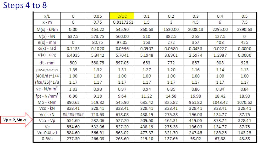
28 Solution Draw BMD and SFD M(x) = 0.5w(Lx-x 2 ) & V(x) = w(0.5l x) Where w = 85 kn/m Check maximum allowable shear stress (Cl ) V = kn < 0.8 fcu or 5 N/mm2 OK
29 Solution Plot Mo on BMD Mo vary along the length of beam since the tendon profile is parabolic which produce the different eccentricity along the length of beam. Eccentricities of tendon along parabolic tendon profile given by: Where = 425mm
30 Solution Distribution of M and Mo along beam span
31
32 Variation of V along beam span
33 Solution Nominal Shear Reinforcement Use R8, < 0.75dt =0.75(908) = 681mm Shear reinforcement Use R8 350 mm V-Vc = kn < 0.75dt =0.75(772) = 579mm Use R8 150 mm
34
5.4 Analysis for Torsion
 5.4 Analysis for Torsion This section covers the following topics. Stresses in an Uncracked Beam Crack Pattern Under Pure Torsion Components of Resistance for Pure Torsion Modes of Failure Effect of Prestressing
7.1 Transmission of Prestress (Part I)
") 7.1 Transmission of Prestress (Part I) This section covers the following topics. Pre-tensioned Members 7.1.1 Pre-tensioned Members The stretched tendons transfer the prestress to the concrete leading to
7.1 Transmission of Prestress (Part I) This section covers the following topics. Pre-tensioned Members 7.1.1 Pre-tensioned Members The stretched tendons transfer the prestress to the concrete leading to
ST7008 PRESTRESSED CONCRETE
 ST7008 PRESTRESSED CONCRETE QUESTION BANK UNIT-I PRINCIPLES OF PRESTRESSING PART-A 1. Define modular ratio. 2. What is meant by creep coefficient? 3. Is the deflection control essential? Discuss. 4. Give
BRITISH CODE IMPLEMENTATION IN 1 ADAPT SOFTWARE
 Structural Concrete Software System TN211_BS8110_implementation_11 082106 BRITISH CODE IMPLEMENTTION IN 1 DPT SOFTWRE This Technical Note details the implementation of the British Code (BS 8110: Part 1:1997)
SECTION 1 INTRODUCTION TO POST-TENSIONED CONCRETE DEVELOPED BY THE PTI EDC-130 EDUCATION COMMITTEE
 SECTION 1 INTRODUCTION TO POST-TENSIONED CONCRETE DEVELOPED BY THE PTI EDC-130 EDUCATION COMMITTEE NOTE: MOMENT DIAGRAM CONVENTION In PT design, it is preferable to draw moment diagrams to the tensile
Fundamentals of Prestressed Concrete Bridge
 Fundamentals of Prestressed Concrete Bridge MAB1053 Bridge Engineering Prof. Dr. Azlan Abdul Rahman Universiti Teknologi Malaysia UTM 2006 azlanfka/utm05/mab1053 1 Introduction In prestressed concrete,
Flexure Design Sequence
 Prestressed Concrete Beam Design Workshop Load and Resistance Factor Design Flexure Design Flexure Design Sequence Determine Effective flange width Determine maximum tensile beam stresses (without prestress)
Lecture Retaining Wall Week 12
 Lecture Retaining Wall Week 12 Retaining walls which provide lateral support to earth fill embankment or any other form of material which they retain them in vertical position. These walls are also usually
CHAPTER 11: PRESTRESSED CONCRETE
 CHAPTER 11: PRESTRESSED CONCRETE 11.1 GENERAL (1) This chapter gives general guidelines required for the design of prestressed concrete structures or members with CFRM tendons or CFRM tendons in conjunction
Chapter. Masonry Design
 Chapter Masonry Design The masonry design section contains modules for the analysis of reinforced masonry beams subjected to pure bending and unreinforced masonry walls subjected to axial compression and
Post-tensioned prestressed concrete bridge - assignment
 Post-tensioned prestressed concrete bridge - assignment Design a post-tensioned prestressed concrete bridge of a three-span arrangement. The construction is prestressed at the age of 7 days and put into
Two-way slabs. Flat plate with or without drop panels / capitals
 Two-way slabs Two-way slab behavior is described by plate bending theory which is a complex extension of beam bending. Codes of practice allow use of simplified methods for analysis and design of two-way
Seismic Detailing of RC Structures (IS: )
") Seismic Detailing of RC Structures (IS:13920-1993) Sudhir K Jain Indian Institute of Technology Gandhinagar November 2012 1 Outline This lecture covers: Covers important clauses of IS13920 With particular
Seismic Detailing of RC Structures (IS:13920-1993) Sudhir K Jain Indian Institute of Technology Gandhinagar November 2012 1 Outline This lecture covers: Covers important clauses of IS13920 With particular
Chapter 5: Introduction To Prestressed Concrete Design
 Chapter 5: Introduction To Prestressed Concrete Design Prepared by: Koh Heng Boon Faculty of Civil & Environmental Engineering 31 October 2012 5.1 Principles of Prestressed Concrete Design Prestressed
DESIGN OF WALLS FOR SHEAR
 mortarless masonry Design Manual Part 3 (IS 456:2000) Section 5 Page: 1 SECTION 5. DESIGN OF WALLS FOR SHEAR Shear walls: Load-bearing walls are mostly designed to carry axial compression loads, however
VTU EDUSAT PROGRAMME Lecture Notes on Design of Stair cases
 VTU EDUSAT PROGRAMME 17 2012 Lecture Notes on Design of Stair cases DESIGN OF RCC STRUCTURAL ELEMENTS - 10CV52 (PART B, UNIT 8) Dr. M. C. Nataraja Professor, Civil Engineering Department, Sri Jayachamarajendra
3. Bond, Anchorage and Shear This chapter will discuss the following topics:
 3. Bond, Anchorage and Shear This chapter will discuss the following topics: Outline the theory of calculating the anchorage bond length. Determination of anchorage bond length, tension lap length and
Strength Design of Reinforced Concrete Structures
 Chapter 6 Strength Design of Reinforced Concrete Structures 6.1 Analysis and Design General Considerations 6.1.1 Convention and Notation Unless otherwise explicitly stated, the following units shall be
Flat Slabs. d 2. A typical flat slab (without drop and column head)
") 1 CHAPTER Flat Slabs 1.1 INTRDUCTIN Common practice of design and construction is to support the slabs by beams and support the beams by columns. This may be called as beam-slab construction. The beams
1 CHAPTER Flat Slabs 1.1 INTRDUCTIN Common practice of design and construction is to support the slabs by beams and support the beams by columns. This may be called as beam-slab construction. The beams
TORSION SIMPLIFIED: A FAILURE PLANE MODEL FOR DESIGN OF SPANDREL BEAMS
 TORSION SIMPLIFIED: A FAILURE PLANE MODEL FOR DESIGN OF SPANDREL BEAMS Gary Klein, Gregory Lucier, Sami Rizkalla, Paul Zia and Harry Gleich Biography: Gary Klein, FACI, is Executive Vice President and
Concrete and Masonry structures 3
 Concrete and Masonry structures 3 133CM03 Model Homework 1 Post-tensioned prestressed concrete bridge - assignment Design a post-tensioned prestressed concrete bridge of a three-span arrangement. The construction
Chapter Five Torsion. Reinforced Concrete Structures 2 (CEng-3122)
") Reinforced Concrete Structures 2 (CEng-3122) Chapter Five Torsion 1 School of Civil and Environmental Engineering Concrete Material and Structures Chair 2 1. Introduction 2. Torsional Resistance 3. Analysis
Reinforced Concrete Structures 2 (CEng-3122) Chapter Five Torsion 1 School of Civil and Environmental Engineering Concrete Material and Structures Chair 2 1. Introduction 2. Torsional Resistance 3. Analysis
Hyperstatic (Secondary) Actions In Prestressing and Their Computation
 Actions In Prestressing and Their Computation") 5.5 Hyperstatic (Secondary) Actions In Prestressing and Their Computation Bijan O Aalami 1 SYNOPSIS This Technical Note describes the definition, computation, and the significance of hyperstatic (secondary)
5.5 Hyperstatic (Secondary) Actions In Prestressing and Their Computation Bijan O Aalami 1 SYNOPSIS This Technical Note describes the definition, computation, and the significance of hyperstatic (secondary)
Nonlinear Models of Reinforced and Post-tensioned Concrete Beams
 111 Nonlinear Models of Reinforced and Post-tensioned Concrete Beams ABSTRACT P. Fanning Lecturer, Department of Civil Engineering, University College Dublin Earlsfort Terrace, Dublin 2, Ireland. Email:
> 0. 1 f, they are treated as beam-columns.
 223 A- Flexural Members (Beams) of Special Moment Frames Requirements of ACI 21.5 are applicable for special moment frame members proportioned primarily to resist flexure with factored axial forces 0.
EN REINFORCED MASONRY DESIGN EXAMPLE 1 (NOTE: THIS USES THE UK NATIONAL ANNEX NDP VALUES)
") 42.50 10.00 3.00 20.00 EN 1996-1-1 REINFORCED MASONRY DESIGN EXAMPLE 1 (NOTE: THIS USES THE UK NATIONAL ANNEX NDP VALUES) Reinforced Masonry - Reinforced Brickwork Stem Cantilever Pocket-Type Retaining
42.50 10.00 3.00 20.00 EN 1996-1-1 REINFORCED MASONRY DESIGN EXAMPLE 1 (NOTE: THIS USES THE UK NATIONAL ANNEX NDP VALUES) Reinforced Masonry - Reinforced Brickwork Stem Cantilever Pocket-Type Retaining
ADAPT-PT 2010 Tutorial Idealization of Design Strip in ADAPT-PT
 ADAPT-PT 2010 Tutorial Idealization of Design Strip in ADAPT-PT Update: April 2010 Copyright ADAPT Corporation all rights reserved ADAPT-PT 2010-Tutorial- 1 Main Toolbar Menu Bar View Toolbar Structure
DESIGN OF POST-TENSIONED MEMBERS IN BENDING USING ACI SIMPLIFIED PROCEDURE
 Structural Concrete Software System TN 179 Aci_simplified_M_design3 011005 DESIGN OF POST-TENSIONED MEMBERS IN BENDING USING ACI 318 2002 SIMPLIFIED PROCEDURE 1. BACKGROUND 1.1 GENERAL The following describes
ADAPT-PTRC 2016 Getting Started Tutorial ADAPT-PT mode
 ADAPT-PTRC 2016 Getting Started Tutorial ADAPT-PT mode Update: August 2016 Copyright ADAPT Corporation all rights reserved ADAPT-PT/RC 2016-Tutorial- 1 This ADAPT-PTRC 2016 Getting Started Tutorial is
One-Way Wide Module Joist Concrete Floor Design
 One-Way Wide Module Joist Concrete Floor Design A 1 3 4 30'-0" 30'-0" 30'-0" 3' B 3' C 3' D 3' E 4" 4" (typ.) 3' F 0" 0" (typ.) Figure 1 One-Way Wide Module Joist Concrete Floor Framing System 1 Overview
3D analysis of solid reinforced concrete beams subjected to combined load of bending, torsion and shear
 ational Methods and Experimental Measurements XIII 85 3D analysis of solid reinforced concrete beams subjected to combined load of bending, torsion and shear A. S. Alnuaimi Civil and Architectural Engineering,
Design of Post Tensioned Slab (Review)
") Design of Post Tensioned Slab (Review) Arun S. Bhutekar, Kishor S. Mirge, Bhavna Mhaske, Mangesh J. Sarkate, Prof,N. N. Shinde Department Civil Engineering, Email: bhutekararun143@gmail.com ABSTRACT- The
Design of Post Tensioned Slab (Review) Arun S. Bhutekar, Kishor S. Mirge, Bhavna Mhaske, Mangesh J. Sarkate, Prof,N. N. Shinde Department Civil Engineering, Email: bhutekararun143@gmail.com ABSTRACT- The
UNIVERSITY OF BOLTON WESTERN INTERNATIONAL CENTRE FZE. BEng (HONS) CIVIL ENGINEERING SEMESTER ONE EXAMINATION 2015/2016
 CIVIL ENGINEERING SEMESTER ONE EXAMINATION 2015/2016") OCD59 UNIVERSITY OF BOLTON WESTERN INTERNATIONAL CENTRE FZE BEng (HONS) CIVIL ENGINEERING SEMESTER ONE EXAMINATION 2015/2016 ADVANCED STRUCTURAL ANALYSIS AND DESIGN MODULE NO: CIE6001 Date: Tuesday 12
OCD59 UNIVERSITY OF BOLTON WESTERN INTERNATIONAL CENTRE FZE BEng (HONS) CIVIL ENGINEERING SEMESTER ONE EXAMINATION 2015/2016 ADVANCED STRUCTURAL ANALYSIS AND DESIGN MODULE NO: CIE6001 Date: Tuesday 12
Ground + 4 floor RCC frame structure in Goa Floor to floor height is 3.0m Plan dimension, 24.0 m x 13.5 m SBC = 20 t/sqm, hard Strata is consider for
 Ground + 4 floor RCC frame structure in Goa Floor to floor height is 3.0m Plan dimension, 24.0 m x 13.5 m SBC = 20 t/sqm, hard Strata is consider for seismic analysis Analysis done using structural designing
Special Reinforced Concrete Structural Walls
 135 Special Reinforced Concrete Structural Walls The requirements of this section apply to special reinforced concrete structural walls serving as part of the earthquake force-resisting system. Shear Strength:
Applications of sustainable post-tensioned concrete slabs
 Innov. Infrastruct. Solut. (2017) 2:42 DOI 10.1007/s41062-017-0075-6 TECHNICAL PAPER Applications of sustainable post-tensioned concrete slabs Amr A. Abdelrahman 1 Received: 4 May 2017 / Accepted: 2 June
Structural Design of Pergola with Airfoil Louvers
 International Journal of Advanced Structures and Geotechnical Engineering ISSN 2319-5347, Vol. 04, No. 03, July 2015 Structural Design of Pergola with Airfoil Louvers MUHAMMAD TAYYAB NAQASH Aluminium TechnologyAauxiliary
DESIGN FOR PROGRESSIVE COLLAPSE 1
 Your Partner in Structural Concrete Design TN447_progressive_collapse_110713 DESIGN FOR PROGRESSIVE COLLAPSE 1 Bijan O Aalami 2 This Technical Note outlines the design of column-supported conventionally
Performance of Pretensioning Prestressed Concrete Beams with Ruptured Strands Flexurally Strengthened by CFRP Sheets
 Perormance o Pretensioning Prestressed Concrete Beams with Ruptured Strands Flexurally Strengthened by CFRP Sheets Thi Thu Dung NGUYEN 1, Koji MATSUMOTO 2, Asami IWASAKI 3, Yuji SATO 3 and Junichiro NIWA
Modelling of RC moment resisting frames with precast-prestressed flooring system
 Modelling of RC moment resisting frames with precast-prestressed flooring system B.H.H. Peng, R.P. Dhakal, R.C. Fenwick & A.J. Carr Department of Civil Engineering, University of Canterbury, Christchurch.
CHAPTER 9 STAIR CASES 9.1 GENERAL FEATURES 9.2 TYPES OF STAIR CASES
 CHAPTER 9 STAIR CASES 9.1 GENERAL FEATURES Stair cases are provided for connecting successive floors. It is comprised with flights of steps with inter mediate landings which provides rest to the user and
Design Guide for Concrete Toppings to Beam & EPS Block Suspended Floors
 Design Guide for Concrete Toppings to Beam & EPS Block Suspended Floors September 2017 Cooperating organizations BBA BPF (British Plastics Federation) British Precast PFF BRMCA Concrete Society Grace Construction
A Guide for the Interpretation of Structural Design Options for Residential Concrete Structures
 CFA Technical Note: 008-2010 A Guide for the Interpretation of Structural Design Options for Residential Concrete Structures CFA Technical This CFA Technical Note is intended to serve as a guide to assist
1. Report No. 2. Government Accession No. 3. Recipient's Catalog No. FHWA/IN/JTRP-2003/5
 1. Report No. 2. Government Accession No. 3. Recipient's Catalog No. FHWA/IN/JTRP-2003/5 TECHNICAL REPORT STANDARD TITLE PAGE 4. Title and Subtitle Simplified Shear Design of Prestressed Concrete Members
BrD Superstructure Tutorial
 AASHTOWare BrD 6.8 BrD Superstructure Tutorial PS12 Prestressed Concrete I Beam Using BrD LRFD Engine BrD Superstructure Training PS12 - Prestressed Concrete I Beam Using BrD LRFD Engine 1'-9" 55'-6" Total
Practical Prestress Detailing
 Practical Prestress Detailing Disclaimer: "This presentation is for guidance only & is not to be taken as specific advice applicable to a particular project." This presentation will only cover bonded post-tensioning,
Shear Behavior of R/C Beams with Web Openings Reinforced by Prestress Force
 ctbuh.org/papers Title: Authors: Subject: Keywords: Shear Behavior of R/C Beams with Web Openings Reinforced by Prestress Force Shizou Hayashi, Professor, Tokyo Institute of Technology Keiichi Katori,
Shear Capacity of Prestressed Concrete Beams
 2007-47 Shear Capacity of Prestressed Concrete Beams Take the steps... Research...Knowledge...Innovative Solutions! Transportation Research Technical Report Documentation Page 1. Report No. 2. 3. Recipients
Executive Summary. Champlain Bridge Approach Spans Edge Girder Condition Assessment and Rehabilitation Requirements.
 Executive Summary "Les Ponts Jacques Cartier et Champlain Incorporée" (PJCCI) requested that Buckland & Taylor (B&T) study the overall condition of the approach span edge girders of the Champlain Bridge
STRENGTHENING OF UNBONDED POST-TENSIONED CONCRETE SLABS USING EXTERNAL FRP COMPOSITES
 STRENGTHENING OF UNBONDED POST-TENSIONED CONCRETE SLABS USING EXTERNAL FRP COMPOSITES F. El M e s k i 1 ; M. Harajli 2 1 PhD student, Dept. of Civil and Environmental Engineering, American Univ. of Beirut;
BRIDGE DESIGN MANUAL UPDATES. Jamie F. Farris, P.E.
 BRIDGE DESIGN MANUAL UPDATES Jamie F. Farris, P.E. October 2015 Table of Contents 1 BDM Chapter 2 Limit States and Loads 2 BDM Chapter 3 Superstructure Design 3 BDM Chapter 4 Substructure Design 4 Questions
Structural behaviour and failure mechanisms of concrete monoblock railway sleepers
 Structural behaviour and failure mechanisms of concrete monoblock railway sleepers Olli Kerokoski, Antti Nurmikolu and Tommi Rantala Department of Civil Engineering, Tampere University of Technology, P.O.
7INDETERMINATE BEAM ANALYSIS
 Chapter 7 7INDETERMINATE BEAM ANALYSIS In this chapter, the local deformation model described in Chapter 4 is incorporated into an analysis of reinforced and partially prestressed continuous beams. A computer
USE OF 500 GRADE STEEL IN THE DESIGN OF REINFORCED CONCRETE SLAB. Prof. M. Shafiul Bari, Ph.D Department of Civil Engg., BUET
 1.0 Introduction USE OF 500 GRADE STEEL IN THE DESIGN OF REINFORCED CONCRETE SLAB Prof. M. Shafiul Bari, Ph.D Department of Civil Engg., BUET There is growing interest within the reinforced concrete industry
BRIDGE GIRDERS TECHNICAL GUIDE
 ARMTEC.COM BRIDGE MATERIALS / / TECHNICAL GUIDE REGIONal SPECIFICATIONS / AB / MB / SK PRECAST CONCRETE GIRDERS AND BEAMS DESIGNED TO SUPPORT BRIDGE DECKS AND TRAFFIC LOADS Proven strength In-house engineering
Fundamentals of Post Tensioned Concrete Design for Buildings
 Fundamentals of Post Tensioned Concrete Design for Buildings Part Three by John P. Miller Overview of This Course This is Part Two of a two-part course that covers the fundamentals of post-tensioned concrete
Example. Monday, October 19, 2015
 Example Monday, October 19, 2015 11:26 AM Using a prestressed Y4 beam with reinforced concrete deck slab as the deck example as shown in Fig.1; the deck having a 10 skew, a span of 20m and carrying a 7.3m
Siddhartha Ray, Molly Mathew, Sanjay Singh3
 nternational Journal of Scientific & Engineering Research, Volume, ssue, December-5 SSN 9-558 Analysis and design of two span continuous preed beam Siddhartha Ray, Molly Mathew, Sanjay Singh P.G student,
OPTIMIZED ALTERNATIVE STRUCTURAL FORMS FOR STANDARD HIGHWAY BRIDGE BEAMS WITH HIGHER STRENGTH CONCRETES
 OPTIMIZED ALTERNATIVE STRUCTURAL FORMS FOR STANDARD HIGHWAY BRIDGE BEAMS WITH HIGHER STRENGTH CONCRETES Abstract K S M Silva, Department of Civil Engineering, University of Moratuwa. Email: mangala_xp@yahoo.com
WATER RESEARCH COMMISSION. KSA 1: Water Resource Management. Thrust 2: Management of Natural and Human-induced Impacts on Water Resources
 WATER RESEARCH COMMISSION KSA 1: Water Resource Management Thrust 2: Management of Natural and Human-induced Impacts on Water Resources P3: Integrated flood and drought management REPORT ON DESIGN CODES
THEORETICAL AND EXPERIMENTAL STUDY OF UNBOUNDED POST-TENSIONED CONTINUOUS SLAB DECKS CONSISTING OF HIGH STRENGTH SCC
 CD02-017 THEORETICAL AND EXPERIMENTAL STUDY OF UNBOUNDED POST-TENSIONED CONTINUOUS SLAB DECKS CONSISTING OF HIGH STRENGTH SCC A.A. Maghsoudi 1, M. Torkamanzadeh 2 1 Associate. Prof., Civil Engineering.
Design and analysis of T and inverted L beams- Theory and Examples
 Design and analysis of T and inverted L beams- Theory and Examples - Dr. E. R. Latifee Reference Book: Design of Reinforced Concrete by Jack C. McCormac and Russell H. Brown, Clemson University, 9 th Edition,
Shear Assessment and Strengthening of Contiguous-Beam Concrete Bridges Using FRP Bars
 SP-230 48 Shear Assessment and Strengthening of Contiguous-Beam Concrete Bridges Using FRP Bars by P. Valerio, T.J. Ibell and A.P. Darby Synopsis: Many concrete bridges related to railways in the U.K.
SHEAR BEHAVIOR OF REINFORCED HIGH-STRENGTH CONCRETE MEMBERS
 SHEAR BEHAVIOR OF REINFORCED HIGH-STRENGTH CONCRETE MEMBERS Saitama University, Japan Perera, S.V.T.J. Saitama University, Japan JPCEA Member, Mutsuyoshi, H. Abstract: This paper describes the diagonal
Sabah Shawkat Cabinet of Structural Engineering 2017
 3.1-1 Continuous beams Every building, whether it is large or small, must have a structural system capable of carrying all kinds of loads - vertical, horizontal, temperature, etc. In principle, the entire
ASD OF CONCRETE MASONRY LINTELS BASED ON THE 2012 IBC/2011 MSJC. TEK 17-1D Structural (2011) Related TEK: 14-7C, 14-13B, 17-1C, 17-2A
 Related TEK: 14-7C, 14-13B, 17-1C, 17-2A") n information series from the national authority on concrete masonry technology SD OF CONCRETE MSONRY LINTELS BSED ON THE 2012 IBC/2011 MSJC TEK 17-1D Structural (2011) INTRODUCTION Lintels and beams are
n information series from the national authority on concrete masonry technology SD OF CONCRETE MSONRY LINTELS BSED ON THE 2012 IBC/2011 MSJC TEK 17-1D Structural (2011) INTRODUCTION Lintels and beams are
User Guide. for Eurocode Modules. Design+ Interface General Column Design Combined Wall Design Strip Foundation Design Design Parameters
 Solution for Structural Member Design with Drawing & Report midas Design + User Guide for Eurocode Modules Design+ Interface General Column Design Combined Wall Design Strip Foundation Design Design Parameters
1. INTRODUCTION BACKGROUND
 1-1 1. INTRODUCTION 1.1. BACKGROUND Various attempts have been made in the past to do reduce the weight of concrete slabs, without reducing the flexural strength of the slab. Reducing the own weight in
PROFESSIONAL DEVELOPMENT SERIES
 Torsion Design of Structural Concrete Based on ACI 318-05 By Mahmoud E. Kamara, Ph.D., and Basile G. Rabbat, Ph.D., S.E. PROFESSIONAL DEVELOPMENT SERIES September 2007 Professional Development Series Torsion
Development of a rational design methodology for precast concrete slender spandrel beams: Part 2, analysis and design guidelines
 Development of a rational design methodology for precast concrete slender spandrel beams: Part 2, analysis and design guidelines Gregory Lucier, Catrina Walter, Sami Rizkalla, Paul Zia, and Gary Klein
Analysis and design of balanced cantilever prestressed box girder bridge considering constructions stages and creep redistribution
 Analysis and design of balanced cantilever prestressed box girder bridge considering constructions stages and creep redistribution 1. Introduction Assoc. Prof. Dr. Amorn Pimanmas Sirindhorn International
Effect of beam dimensions on structural performance of wide beam-column joints
 Effect of beam dimensions on structural performance of wide beam-column joints J.S. Kuang 1) and *Wing Shan Kam 2) 1), 2) Department of Civil and Environmental Engineering, Hong Kong University of Science
Design Aids of NU I-Girders Bridges
 Nebraska Transportation Center Report SPR-P1(09) P322 Final Report 26-1120-0042-001 Design Aids of NU I-Girders Bridges Kromel E. Hanna, Ph.D. Department of Civil Engineering University of Nebraska-Lincoln
SHEAR STRENGTH CAPACITY OF PRESTRESSED CONCRETE BEAM- COLUMN JOINT FOCUSING ON TENDON ANCHORAGE LOCATION
 th World Conference on Earthquake Engineering Vancouver, B.C., Canada August -6, Paper No. SHEAR STRENGTH CAPACITY OF PRESTRESSED CONCRETE BEAM- COLUMN JOINT FOCUSING ON TENDON ANCHORAGE LOCATION Wei YUE,
PROFESSIONAL DEVELOPMENT SERIES
 Post-Tensioning for Two-Way Flat Plate Construction By Amy Reineke Trygestad, P.E. PROFESSIONAL DEVELOPMENT SERIES October 2005 Professional Development Series Every major metropolitan area is getting
KSK COLLEGE OF ENGINEERING AND TECHNOLOGY DEPARTMENT OF CIVIL ENGINEERING CE 2505-DESIGN OF RC ELEMENTS QUESTION BANK
 KSK COLLEGE OF ENGINEERING AND TECHNOLOGY DEPARTMENT OF CIVIL ENGINEERING CE 2505-DESIGN OF RC ELEMENTS QUESTION BANK PARTA UNIT I 1. What are the advantages of limit state method over working stress and
Comparative Study on Post - Tensioned and Reinforced Concrete flat Slab Systems for a Multistory Building
 Comparative Study on Post - Tensioned and Reinforced Concrete flat Slab Systems for a Multistory Building Thayapraba M Civil Department, NIT Trichy, (India) ABSTRACT Designers have a huge number of choices
Types of Foundations
 Shallow Foundations Types of Foundations Foundations can be classified to two major categories: Shallow. Deep. 1 Introduction If the soil stratum is suitable for supporting the structural loads from the
Strengthening Effect on Prestressed Concrete members Affected by Alkali-Silica Reaction(ASR)
") Strengthening Effect on Prestressed Concrete members Affected by Alkali-Silica Reaction(ASR) Yukio Takebe 1, Takanobu Yokoyama 2, Hideshige Yonekawa 3, Kenichi Nakamura 4, Toyoaki Miyagawa 5 1 DPS Bridge
Strengthening Effect on Prestressed Concrete members Affected by Alkali-Silica Reaction(ASR) Yukio Takebe 1, Takanobu Yokoyama 2, Hideshige Yonekawa 3, Kenichi Nakamura 4, Toyoaki Miyagawa 5 1 DPS Bridge
PRELOADING EFFECT ON LOAD CAPACITY AND DUCTILITY OF RC BEAMS STRENGTHENED WITH PRESTRESSED CFRP STRIPS
 PRELOADING EFFECT ON LOAD CAPACITY AND DUCTILITY OF RC BEAMS STRENGTHENED WITH PRESTRESSED CFRP STRIPS Renata Kotynia Ph.D., Assistant Professor Technical University of Lodz, Poland Al. Politechniki 6,
Experimental investigation on the shear capacity of RC dapped end beams and design recommendations
 Structural Engineering and Mechanics, Vol. 21, No. 2 (2005) 221-235 221 Experimental investigation on the shear capacity of RC dapped end beams and design recommendations Quanfeng Wang and Zixiong Guo
Behavior and Strength of Slab-Edge Beam-Column Connections under Shear Force and Moment
 Behavior and Strength of Slab-Edge Beam-Column Connections under Shear Force and Moment Omar M. Ben-Sasi Abstract A total of fourteen slab-edge beam-column connection specimens were tested gradually to
Shear studs in slab-column connections with rectangular column
 Shear studs in slab-column connections with rectangular column C B Tan*, Nanyang Techological University, Singapore s C Lee, Nanyang Techological University, Singapore s Teng, Nanyang Techological University,
APPENDIX B ABC STRUCTURES DESIGN GUIDE
 APPENDIX B ABC STRUCTURES DESIGN GUIDE The Cohos Evamy Partners TABLE OF CONTENTS Page No. DISCLAIMER... I 1. STRUCTURAL DESIGN GUIDELINES... 1 2. GENERAL REQUIREMENTS (FIGURE B.2, STEP 1)... 1 3. GENERAL
Design for earthquake-resistent reinforced concrete structural walls
 DOI 10.1007/s11012-014-9877-1 EXPERIMENTAL SOLID MECHANICS Design for earthquake-resistent reinforced concrete structural walls N. St. Zygouris G. M. Kotsovos D. M. Cotsovos M. D. Kotsovos Received: 30
Section A A: Slab & Beam Elevation
 CE 331, Spring 2011 Flexure Strength of Reinforced Concrete s 1 / 5 A typical reinforced concrete floor system is shown in the sketches below. The floor is supported by the beams, which in turn are supported
In-plane testing of precast concrete wall panels with grouted sleeve
 In-plane testing of precast concrete wall panels with grouted sleeve P. Seifi, R.S. Henry & J.M. Ingham Department of Civil Engineering, University of Auckland, Auckland. 2017 NZSEE Conference ABSTRACT:
Precast concrete double-tee beams with thin stems
 Dapped ends of prestressed concrete thin-stemmed members: Part 1, experimental testing and behavior Amir W. Botros, Gary J. Klein, Gregory W. Lucier, Sami H. Rizkalla, and Paul Zia Precast concrete double-tee
SERVICEABILITY LIMIT STATES OF CONCRETE BEAMS PRESTRESSED BY CFRP BARS
 SERVICEABILITY LIMIT STATES OF CONCRETE BEAMS PRESTRESSED BY CFRP BARS by Amr A. Abdelrahman(l) and Sami H. Rizkalla(2) Abstract The non-corrosive and high strength-to-weight ratio characteristics of carbon
The use of 0.5 and 0.6 in. (13 and 15 mm) diameter
 diameter") Benefits of using.7 in. (18 mm) diameter strands in precast, pretensioned girders: A parametric investigation Jessica Salazar, Hossein Yousefpour, Alex Katz, Roya Alirezaei Abyaneh, Hyun su Kim, David
Benefits of using.7 in. (18 mm) diameter strands in precast, pretensioned girders: A parametric investigation Jessica Salazar, Hossein Yousefpour, Alex Katz, Roya Alirezaei Abyaneh, Hyun su Kim, David
Universal Beam and Universal Column sections subject to pure bending are all Class 3 semi-compact or better.
 RESTRAINED BEAMS Sunday, September 27, 2015 11:33 PM The top flange of a simply supported beam subject to gravity loads will be in compression and like any element in compression will try to buckle. The
Part B: Design Calculations
 Part B: Design Calculations Table of Contents Part B: Design Calculations... i Chapter 1: Introduction... 1-1 Chapter 2 Project Statement... 2-1 2.1 Introduction... 2-2 2.2 Geometric properties... 2-3
The Hashemite University Department of Civil Engineering. Dr. Hazim Dwairi. Dr. Hazim Dwairi 1
 Department of Civil Engineering Lecture 2.1 Methods of Prestressing Advantages of Prestressing Section remains uncracked under service loads Reduction of steel corrosion (increase durability) Full section
Moment curvature analysis of concrete flexural members confined with CFRP grids
 Materials Characterisation V 131 Moment curvature analysis of concrete flexural members confined with CFRP grids A. Michael & P. Christou Department of Civil Engineering, Frederick University, Cyprus Abstract
PLASTICITY APPLICATIONS IN REINFORCED CONCRETE AND PRESTRESSED CONCRETE STRUCTURES
 PLASTICITY APPLICATIONS IN REINFORCED CONCRETE AND PRESTRESSED CONCRETE STRUCTURES Ganga PRAKHYA Sir Robert McAlpine Design Group, Eaton Court, Maylands Avenue, Hemel Hempstead,UK Keywords: plasticity,
Prestressed Concrete Girder Continuity Connection
 Report No: Title: Developing Organization: Precast/Prestressed Concrete Institute Technical Committee Phone - 888-700-5670 Email contact@pcine.org Website- www.pcine.org Report Date: Revision Date: Status
Effect of Bar-cutoff and Bent-point Locations on Debonding Loads in RC Beams Strengthened with CFRP Plates
 CICE 2010 - The 5th International Conference on FRP Composites in Civil Engineering September 27-29, 2010 Beijing, China Effect of Bar-cutoff and Bent-point Locations on Debonding Loads in RC Beams Strengthened
DIRECT DESIGN METHOD DDM
 DIRECT DESIGN METHOD DDM Load Transfer Path For Gravity Loads All gravity loads are basically Volume Loads generated due to mass contained in a volume Mechanism and path must be found to transfer these
AASHTO LRFD. Reinforced Concrete. Eric Steinberg, Ph.D., P.E. Department of Civil Engineering Ohio University
 AASHTO LRFD Reinforced Concrete Eric Steinberg, Ph.D., P.E. Department of Civil Engineering Ohio University steinber@ohio.edu Ohio University (July 2007) 1 AASHTO LRFD This material is copyrighted by Ohio
Substructure systems, specifically retaining walls
 Design principles of totally prefabricated counterfort retaining wall system compared with existing cast-in-place concrete structures Maen Farhat and Mohsen Issa An alternative to cast-in-place concrete