Animal Drink Delivery
|
|
|
- Shauna Young
- 6 years ago
- Views:
Transcription


1 Animal Drink Delivery 91
2 92
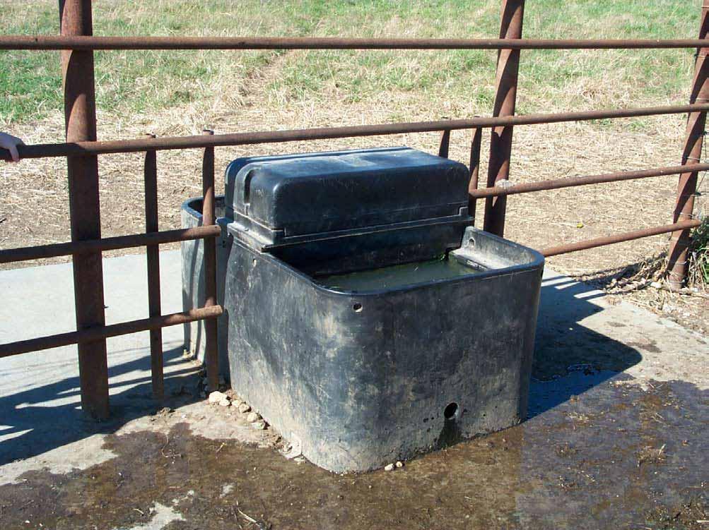
3 Concrete Waterers Overview Concrete waterers provide reliable, durable watering sources. They can be installed as gravity-flow systems, eliminating the need for a power source. The area around the waterer can be easily protected with a geotextile and gravel surface. Fenceline installations allow watering two grazing areas with one waterer. Advantages Allows relocation of the water source to reduce or eliminate direct stream and pond access by livestock Livestock often prefer to drink from a trough Long useful life Can be installed to be freeze resistant Does not require high water pressure Low operation costs Used in conjunction with fencing of pond, improves pond water quality and life of pond Minimal maintenance requirements Producer can install Multiple concrete waterers can be plumbed into a waterline if the grade is sufficiently steep Can be used with non-pressurized (gravity flow) and pressurized water sources with equal success Does not require a poured concrete pad Many tank models to choose from Limitations Tanks are heavy, weighing between 2,300 and 3,000 pounds each Shipping costs may be high Not available at most farm supply stores If a pond is the water source, it must have a livestock water pipeline under, through or around the pond dam 93
4 94 Earth Fill Over Waterer Concrete Waterer Water 4 x 6 Treated Posts Set 48 in ground and imbedded in concrete. Set 54 apart. (or all concrete) 2 x 8 Treated Planking 24 Minimum Earth Fill Drill 5/16 holes Float Valve Overflow (optional) Shut-off Water Supply Hardened Mat Gravel Fill Hand-shaped depression for tank drainage and cleaning.
5 Concrete Waterer Design Considerations The waterer should be placed on a well-drained gravel or sand site that offers some protection from the wind if the waterer will be used during the winter. The site should include an area of about 15 feet square in front of the waterer for cattle to stand. This pad area can be covered with geotextile cloth and gravel of 1-2 inches in diameter. The waterer should be located at least 4 feet below the water level in the pond and beneath the dam for positive gravity flow. The pipeline should be buried below the frost line. After waterer installation, dirt will need to be piled around the back and sides to prevent freezing. The pipeline can be placed either under the dam (new pond construction), or through the dam or out the side of the pond (existing ponds). Usually the trench is constructed from the waterer back towards the pond, stopping about 2 feet from the pond edge. The pipe is laid in the trench, starting at the valve at the waterer end. It is very important to seal the space around the pipeline within 20 feet of the edge of the pond using an anti-seep collar or bentonite clay. The rest of the trench can be excavated into the pond, going deeper as necessary. The trench must extend far enough into the pond to place the pipe inlet where the water is deepest. Installation instructions can be obtained by contacting your watershed specialist or viewing tand by viewing Adopt a Drop: We Can t All Be Up a Creek ( htm). A description of installation is given in the K-State Research and Extension publication Alternative Livestock Watering: Covered Concrete Water, MF-2737, July
6 96
7 Limited Access Watering Points Overview Ponds and streams are common sources of livestock water in Kansas. However, allowing unlimited access can cause severe bank erosion, poor water quality and other related problems. Cattle prefer clean water and avoid steep, muddy approaches to water sources whenever possible. Developing access watering points with a hardened surface and fencing is often fairly simple and solves many of these concerns. Advantages Simple and inexpensive Improved livestock safety and health, less foot rot and fewer leg injuries Reduced bank erosion Less sediment and fewer nutrients entering streams and ponds Extended pond life Applicable to new and existing ponds Increased water intake may mean better livestock gains Limitations Not adapted to large streams Fence maintenance required when stream floods Few options for location of watering point Few examples in Kansas 97
8 98
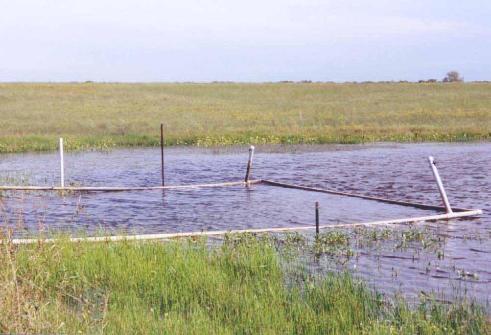
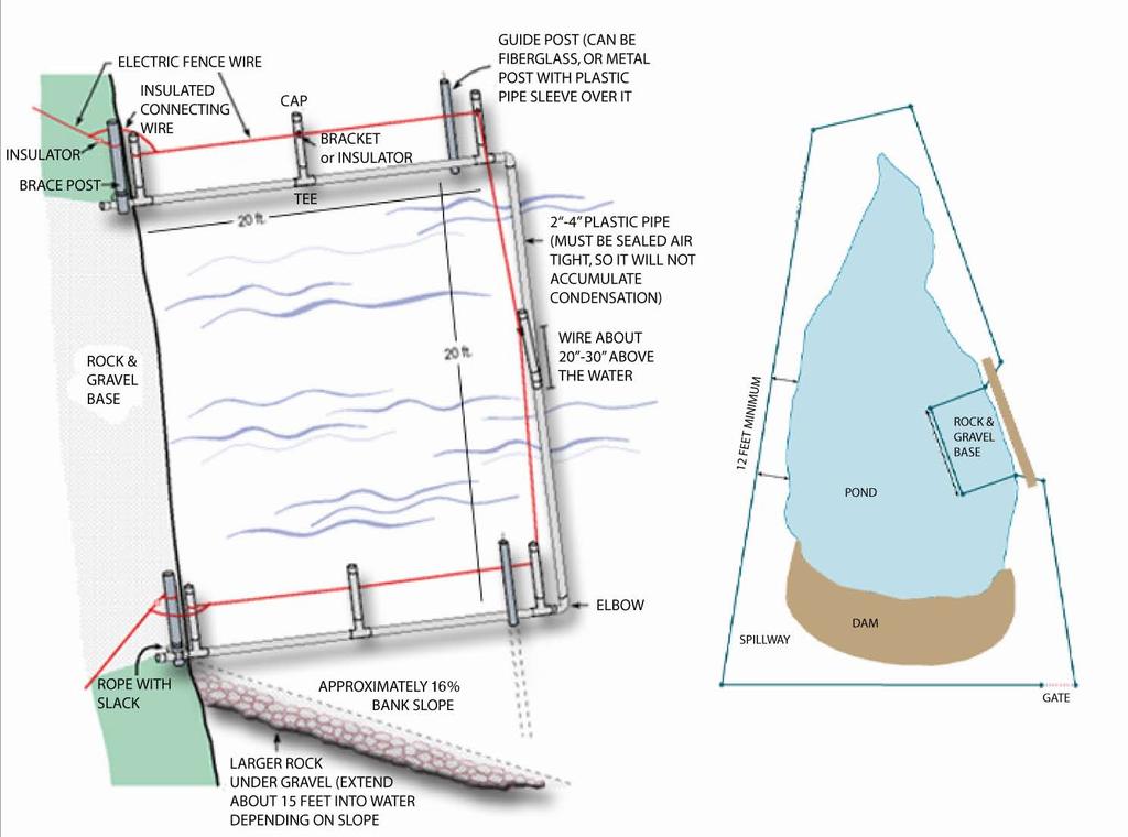
9 Limited Access Watering Points Design Considerations To encourage animal use, an access ramp or walkway should have a maximum slope of 6:1 run to rise (17%) or a 10 degree slope. Ramps as steep as 4:1 have been used. However, a flatter slope (8:1 to 20:1) is generally better when space allows, especially when conditions are icy. The ramp surface should be compacted and non-slip (crushed rock, gravel or concrete). A 3:1 slope (or flatter) for the sides of the ramp is preferable when site conditions permit. Width may vary (recommendations range from 4 to 80 feet) but a good guideline is 10 feet plus one foot for each 10 head of cattle for example, 55 feet for 50 head. Fencing is generally desirable to exclude livestock from other parts of the pond or stream, especially if they congregate and loaf during hot days. A floating fence made of PVC pipe can be used to restrict acess to the pond reservoir at a cost of $ A 16-foot stream crossing/access point for small streams, using gravel with geotextile and sand base, can be constructed for less than $500. This practice may require permits. Please read the permit section of this handbook (p. 143). References Porter, M.D. and J.S. McNeill Livestock water access point in pond fence. The Samuel Roberts Noble Foundation, Ardmore, OK. Porter_PondAccess.htm Natural Resources Conservation Service Conservation practice standard: access road. Code 560. USDA. ftp://ftpfc.sc.egov.usda.gov/nhq/practice-standards/standards/560.pdf Natural Resources Conservation Service Conservation practice standard: heavy use area protection. Code 561. USDA. ftp://ftp-fc.sc.egov.usda.gov/nhq/practice-standards/ standards/561.pdf 99
10 100
11 Hardened Surface Access Overview Properly designed and installed hardened crossings provide a safe, permanent area for livestock and equipment to cross streams without becoming bogged in the mud. Advantages Easily adapted to various stream sizes and locations Quick installation Long useful life Low maintenance Does not create stream obstruction Does not impair stream flow When used in conjunction with fencing, improves water quality by limiting livestock access to stream. Does not require poured concrete Limitations Can be expensive 101
12 102
13 Hardened Surface Access Design Considerations Crossings should always be placed on riffles never in pools and should be placed perpendicular to stream flow. The crossing surface should be at an elevation equal to streambed elevation. Geotextile fabric should be placed under the rock or gravel fill material. This practice may require permits. Please read the permit section of this handbook (p. 143). 103
14 104
15 Super-Insulated Waterer Overview Ice-free water is a challenge for livestock producers in colder climates. Experience with many different types of waterers has led major companies and producers to consider products with much higher insulation values (R-factor resistance to heat flow). Producers have reported problems with heating elements or burners in their waterers that are designed to preventing freezing. Greater acceptance of molded-plastic use around livestock has led to manufacture of super-insulated plastic waterers. In most cases super-insulated waterers have operated very well in the central U.S. without use of auxiliary electric heating elements or gas burners. Advantages No need for supplemental heat to prevent freeze-up Available from local farm supply stores Availability of parts is good Livestock learn to use them easily Does not rust Uses UV-resistant molded plastic Limitations Requires more frequent checking than other types of waterers Can be damaged if allowed to freeze repeatedly (left with no livestock) Requires a solid or concrete base 105
16 106 Concrete Footing (3 deep, 6-8 thick) Level Control Valve Water Supply Pipe Insulation Water Displaceable Insulating Seal Insulated Box Sealed Connection to Concrete Base Air-gap allows warm air from below soil freeze line to contact the tank.
17 Super-Insulated Waterer Design Considerations Combining use of a vertical earth tube into the ground below the waterer with the warmth of the water as it enters the waterer generally provides enough energy to prevent ice from forming inside the waterer. When water colder than normal groundwater temperature is used, such as pond water or spring water, the chance of freezing is greater. These waterers utilize a variety of doors or covers to retain the intrinsic heat of the water and to seal cold air and wind out. Most waterers use either a large ball that floats tight against the inside of the tank or a door that the livestock open in order to access the water. Occasionally these doors or balls will freeze shut; however, a bump or tap by the producer will open the door or dislodge the ball. Livestock easily learn how to access the water. These tanks rely on a significant volume of warmer water to prevent freezing, so the number of livestock per waterer should be adjusted to ensure that the waterer will refill periodically with warmer water. The producer will normally find that in the central U.S., a flow through (or use) of two or three volumes of water is required on the coldest days to prevent freezing. Most companies recommend at least head per waterer. These waterers can be placed in a fence line to allow more livestock to use a waterer. Producers are cautioned to check these energy free waterers twice a day; in the morning to make sure that livestock can access the water, and again near evening to assure the float and valve are operating properly. Super insulated waterers should be placed in a location protected from the wind and snow to minimize heat loss and reduce the chance of freezing. A site exposed to the sun also reduces the probability of the waterer freezing. Most super-insulated waterers require a solid base such as a concrete pad. A good gravel base around the concrete pad should be considered. Refer to Geotextile and Gravel Surrounds on p
18 108
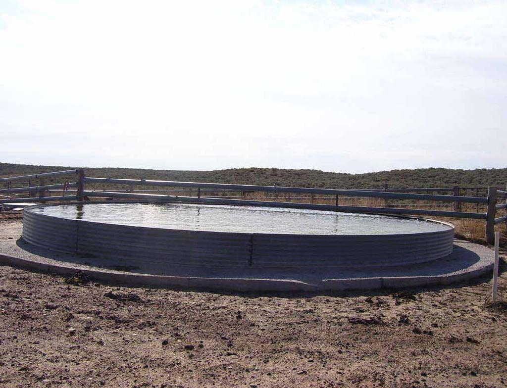
19 Bottomless Tank Overview Bottomless tanks are large, open-topped tanks used for storing water and watering livestock. They are most often made of corrugated metal sections, such as grain bin sections, bolted together to form a large circular ring on site. A bottom is constructed inside the tank after it is assembled and placed in position. The bottom is usually made of bentonite clay, concrete or PVC plastic membrane. Because bottomless tanks come unassembled, very large (20 feet or larger diameter) tanks are possible. Tanks this size would be prohibitively expensive to ship if they were already assembled. Because of their water storage capacity these tanks can compensate for the variable water output of windmill and solar panel systems, assuring an adequate supply of livestock water at all times. Livestock drink directly from bottomless tanks. Advantages Simple construction Easily adaptable to most sites Large capacity at comparatively low cost compared with other tanks Can be constructed with on-farm labor Serves as both water storage and drinking device Limitations Tank will eventually need to be rebuilt due to soilstructure properties Can be relocated, but only with much time, effort and expense 109
20 in diameter 30 deep Concrete foundation and bottom
21 Bottomless Tank Design Considerations Bottomless tanks are generally inches deep and 20 feet or more in diameter. The lower part of the wall is embedded into the tank bottom material. The tank bottom is susceptible to soil shifting and to changes in soil temperature and moisture. Minor maintenance is required on a regular basis. With substantial effort, tanks can be disassembled, moved, and reassembled at another location. 111
22 112
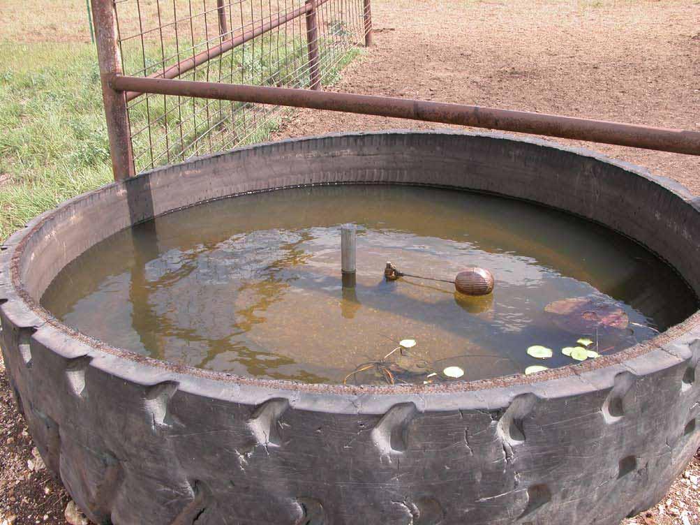
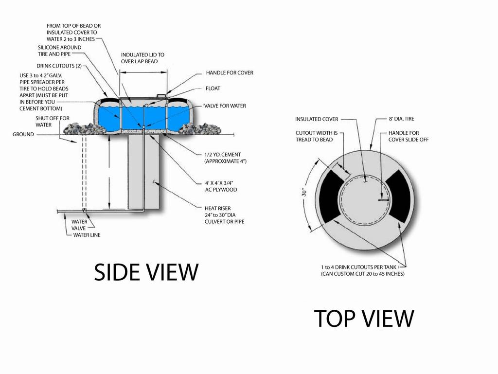
23 Tire Tank Overview Used rubber tires from heavy earth-moving or construction equipment have been adapted for use as reliable livestock water tanks. They have proven to be durable, relatively inexpensive, and capable of being used with a variety of water sources. In numerous situations and settings, they are freezeresistant in winter. Advantages Simple and generally inexpensive Available in a variety of sizes Durable and non-breakable; no sharp edges to injure livestock Can be used with waterlines from wells, springs, and new or existing ponds Freeze-resistant in winter if some protection provided Limitations Heavy to handle during installation Limited size may limit water storage for larger herds Removal of part or all of one sidewall to make tank is usually difficult 113
24 114
25 Tire Tank Design Considerations Rubber tire tanks are normally supplied via pipeline from wells, springs or ponds. Choose tanks based on the size of the herd to be watered and the supply rate of the water source. Sizes range from 5 to 15 or more feet in diameter. Width of the tire (tank height) can be as much as four feet. The sidewall of the tire is cut away in part or entirely on the topside to allow drinking access. Cutting fewer holes will improve the freeze resistance of the tank while cutting away the entire sidewall will allow more livestock to drink at one time. Larger tires can be partially buried for some protection from freezing and to reduce the height of the tires, allowing access for smaller animals. Use a heavy-duty saw to cut and remove part or all of the sidewall on the upper side to allow livestock easy access to water. The pipeline riser supplying the water (inlet) should be placed in the center of the tire or otherwise protected from breakage by livestock. A supply line of one to two inch PVC pipe is generally installed. A pipe joint at the base of the riser is recommended to allow easy replacement in case the top portion is broken. Most tire tanks are fitted with some type of float or shut-off valve. An overflow line is not installed except when the tank is part of a spring development and an overflow line is needed to carry away excess inflow or prevent freezing. Use concrete, bentonite or other heavy clay to seal the lower side of the tire at ground level to prevent leakage. Tanks may be partially buried or soil mounded part of the way up the sides to reduce fluctuations in water temperature. Placing a layer of coarse gravel or other similar material around the tank will provide a durable, hardened surface and eliminate muddy conditions. Placing a deck of used railroad ties adjacent to the tire will help give small calves access to the water. Building a protective railing over the tank is recommended to keep animals from being pushed into the tank and away from piping and floats. Most rubber tire tanks can be installed for a few hundred dollars. Some construction companies will give away used tires at construction sites simply to have them removed. Tires are also available from several suppliers. Examples of tire tanks can be viewed at Hole cut through tire to allow livestock access Large, heavy-duty tire with concrete poured in bottom to hold water Hole cut through tire to allow livestock access 115
26 116
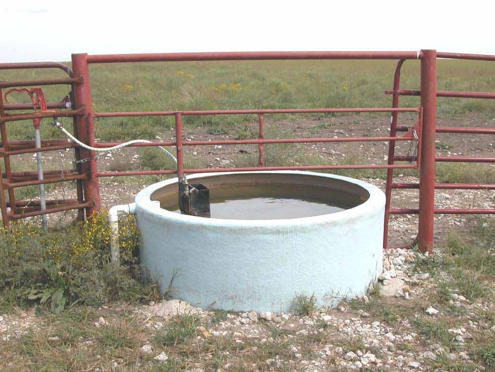
27 Fiberglass or Galvanized Tank Overview Portable tanks are an important part of livestock watering. Galvanized steel and fiberglass tanks are the two types commonly used. They are considered portable because they are reasonably light weight compared with other options. Empty tanks are easy to move for a temporary need. Tanks are suitable for watering a large number of animals at a time and are generally economical. Advantages Water quality in a tank is usually better than cattle drinking directly from a pond A single tank can serve more than one paddock or lot Can be easily moved when needed Can be located/relocated to improve cattle distribution in a paddock A large tank allows several animals to drink at once Because of stored water the larger the tank the smaller the water delivery capacity needed to supply the animals Tanks work well for hauled water Portable tanks can be moved regularly to avoid mudholes developing around the tank Limitations Soil around the waterer can become muddy from cattle dripping and depressions that develop and collect rainfall Manufactured tanks may be more costly than a used tire tank and are more susceptable to damage Galvanized steel and fiberglass tanks don t last as long as concrete tanks; probably not the best choice for a permanantly-located waterer Galvanized tanks will eventually rust Empty and unsecured tanks can be blown away or stolen Large tanks are awkward to move 117
28 118
29 Fiberglass or Galvanized Tank Design Considerations Tanks should be sited on well-drained level ground. Water should drain away from the tank to help avoid a mud hole around the tank site. Be sure the site is prepared by removing any rocks and making the area level. Sharp rocks can puncture the bottom of tanks. Galvanized and fiberglass tanks that are supplied by a gravity or pressured water source need a method to prevent overflow. Options include floats that will shut off the water supply when the tank is full or an overflow that drains by gravity into a low spot or draw that is at least 50 feet from the tank. The tank should be sized to meet the needs for the number of animals it will supply. If the pasture is large, the tank should be able to supply all animals within about 30 minutes (a drinking event) without lowering the water level more than about 10 inches. This means that the water contained in the 10-inch water-level drop plus the inflow during the drink time are adequate to supply one drinking event. During the winter, water in tanks will freeze on the surface and holes must be chopped through the ice so cattle can drink. When sufficient flow is available, tanks fed by groundwater should have an overflow to allow a trickle or low flow through it during the winter to minimize freezing. Groundwater is a fairly constant temperature of about 55 degrees in Kansas. To avoid mud around permanent tank locations, the space around the tank should be protected by a hard surface or draining hard material such as gravel or geotextile-gravel surfacing. Rock that is about 2 inches in diameter will be uncomfortable enough that cattle won t linger by the water and destroy surrounding vegetation. Concrete is an excellent long life surfacing material but is expensive. Soil cement or fly ash should be less expensive options that provide a durable hard surfacing, but with a shorter life than concrete. Portable tanks can easily be moved from time to time to avoid destroying grass and creating a mud hole. Water supply lines can be flexible above ground pipe. 119
30 120
Livestock Watering Systems
 Livestock Watering Systems Mark Green Lead Resource Conservationist USDA-NRCS Springfield, MO Water is generally the MOST Limiting Factor in Grazing Distribution and Maintaining Flexibility of a Grazing
Livestock Watering Systems. Mark Green Lead Resource Conservationist USDA-NRCS Springfield, MO
 Livestock Watering Systems Mark Green Lead Resource Conservationist USDA-NRCS Springfield, MO 1 Water is generally the MOST Limiting Factor in Grazing Distribution and Maintaining Flexibility of a Grazing
Pasture Water Systems for Livestock
 Revised May 2003 Agdex 400/716-3 Pasture Water Systems for Livestock In the past, livestock were turned out to pasture and allowed to walk through and drink from any slough, creek, river or lake available
Remote Pasture Water Systems for Livestock
 December 2007 Agdex 400/716 (C30) Remote Pasture Water Systems for Livestock In the past, livestock were turned out to summer pasture and allowed to walk through and drink from any slough, creek, river,
General Brick Installation Instructions
 Excellent Resource for Clay Paver Installation: http://www.bia.org/resources/clay-brick-pavers/clay-paver-informational- Resources These are general guidelines only. Check your paver manufacturer's recommendations
Chapter 10. Pipeline Installation
 Chapter 10 CHAPTER 10 STOCKWATER PIPELINE INSTALLATION TABLE OF CONTENTS PART 10.1 TRENCHING 10-1 10.1.1 Backhoe Constructed Trench 10-1 10.1.2 Trencher Constructed Trench 10-1 10.1.3 Backfilling and Maintenance
By Jerry Turrentine, NRCS Biologist USDA Natural Resources Conservation Service
 Appendix O By Jerry Turrentine, NRCS Biologist USDA Natural Resources Conservation Service 100 WILDLIFE WATERING FACILITIES DESIGNS AND DRAWINGS Designs for wildlife watering facilities can be simple or
Keeping the Cows in the Corn Even During the Winter Storm. SARE National Conference August 15-17, 2006 Oconomowoc, Wisconsin Don Struxness
 Keeping the Cows in the Corn Even During the Winter Storm SARE National Conference August 15-17, 2006 Oconomowoc, Wisconsin Don Struxness Wintering Our experience with water Our experience with windbreaks
POND CONSTRUCTION. Woodland Steward Series
 POND CONSTRUCTION Woodland Steward Series BOB TWOMEY DISTRICT CONSERVATIONIST USDA NATURAL RESOURCES CONSERVATION SERVICE COURSE OUTLINE DEFINITION OF A POND OR LAKE TYPES OF PONDS GEOLOGIC CONSIDERATIONS
Modular Sediment Barriers (Instream)
") Modular Sediment Barriers (Instream) INSTREAM PRACTICES Flow Control No Channel Flow Dry Channels Erosion Control Low Channel Flows Shallow Water Sediment Control High Channel Flows Deep Water Symbol Photo
Modular Sediment Barriers (Instream) INSTREAM PRACTICES Flow Control No Channel Flow Dry Channels Erosion Control Low Channel Flows Shallow Water Sediment Control High Channel Flows Deep Water Symbol Photo
Proper Construction of detention and sediment basins and their conversions
 Proper Construction of detention and sediment basins and their conversions By Chris Droste, CESCO Senior Erosion Control Specialist Westmoreland Conservation District Discussed topics Pond embankment construction
CITY OF SCHERTZ TEXAS ENGINEERING AND PUBLIC WORKS
 TEXAS STANDARD CONSTRUCTION NOTES DRWN. BY: DSGN. BY: KJW 1 of 2 *Place geotextile fabric as a permeable seperator to prevent mixing of coarse aggregate and underlying soil. (as needed). 1. GEOTEXTILE
Lyon Creek Cedar Way Stormwater Detention Dam Operation and Maintenance Manual
 Lyon Creek Cedar Way Stormwater Detention Dam Operation and Maintenance Manual Prepared by: Mike Shaw Stormwater Program Manager City of Mountlake Terrace January 2010 Section I General Information This
Suggested Stormwater Management Practices For Individual House Lots
 Suggested Stormwater Management Practices For Individual House Lots These practices are necessary to satisfy the water quantity and water quality criteria of the Rappahannock Stormwater Ordinance. These
Construction Inspection Checklists
 III. Construction Inspection Checklists 33 Bioretention - Construction Inspection Checklist Project: Location: Site Status: Date: Time: Inspector: Construction Sequence Satisfactory / Unsatisfactory Comments
Livestock Waterers. WaterWell 4. WaterWell 2. WaterPro 2
 Livestock Waterers WaterWell 4 WaterWell 2 WaterPro 2 www.tru-test.com 800 874 8494 In it together The way we see it, nobody is more dedicated to their work than livestock producers. Solving problems is
SECTION EROSION CONTROLS
 SECTION 31 25 13 EROSION CONTROLS PART 1 GENERAL 1.1 SUMMARY A. Section Includes installing, maintaining and removing: 1. Silt Fence. 2. Temporary Construction Entrances. 3. Diversion Channels. 4. Sediment
Voluntary Water Quality Conservation Plan
 Voluntary Water Quality Conservation Plan Plan Table of Contents A. Mid Coast Agricultural Water Quality Management Area Rules and Plan Overview B. Landowner Resource/Practice Inventory C. Recommended
B. Base Course: Aggregate layer placed between the subbase course and hot-mix asphalt paving.
 SECTION 312000 - EARTH MOVING PART 1 - GENERAL 1.1 SUMMARY A. Section Includes: 1. Excavating and filling for rough grading the Site. 2. Preparing subgrades for walks, curbs, pavements, and turf and grasses.
Background. AEM Tier 2 Worksheet Farmstead Water Supply Evaluation. AEM Principle: Glossary
 AEM Tier 2 Worksheet Glossary Casing: Steel or plastic pipe installed while drilling a well, to prevent collapse of the well bore hole and the entrance of contaminants, and to allow placement of a pump
Inlet Protection. Fe= (Depends on soil type)
") 3.4 DESIGN CRITERIA: KEY CONSIDERATIONS Evaluate drainage patterns to ensure inlet protection will not cause flooding of roadway, property or structures Never block entire inlet opening Size according
3.4 DESIGN CRITERIA: KEY CONSIDERATIONS Evaluate drainage patterns to ensure inlet protection will not cause flooding of roadway, property or structures Never block entire inlet opening Size according
Dome Deck Methods 1. Portable Pie Piece or Star Method 2. Stationary Joist Method 3. Perimeter Boards
 Dome Deck Methods Erecting the dome on a pre-existing deck can be problematic. Please contact us if you plan to do so. Also contact us if your dome has a pre-hung door placement that may require modifications
1993 SPECIFICATIONS CSJ SPECIAL SPECIFICATION ITEM 4110 CONCRETE ENCASED DUCT BANK
 1993 SPECIFICATIONS CSJ 581-1-95 SPECIAL SPECIFICATION ITEM 4110 CONCRETE ENCASED DUCT BANK 1. DESCRIPTION. This Item shall govern for the furnishing and installation of all materials and equipment for
SC-01 Surface Outlet and Baffle Sediment Basin
 Greenville County Technical Specification for: SC-01 Surface Outlet and Baffle Sediment Basin 1.0 Surface Outlet and Baffle Sediment Basin This Specification contains requirements for the design and construction
ITEM 750 ROCK FILTER DAMS
 AFTER MARCH 1, 2012 ITEM 750 ROCK FILTER DAMS 750.1 Description. This work shall consist of the installation of temporary erosion protection and sediment control rock filter dams utilized during construction
ITEM 706 PIPE SLOPE DRAIN
 AFTER NOVEMBER 1, 2008 ITEM 706 PIPE SLOPE DRAIN 706.1 Description. This work shall consist of the installation of temporary erosion protection and sediment control pipe slope drains, utilized during construction
SECTION EROSION CONTROL DEVICES
 SECTION 02374 PART 1 GENERAL EROSION CONTROL DEVICES 1.1 SUMMARY A. Section Includes: 1. Diversion Channels. 2. Rock Energy Dissipator. 3. Paved Energy Dissipator. 4. Rock Basin. 5. Rock Barriers. 6. Sediment
TECHNICAL SPECIFICATION
 TECHNICAL SPECIFICATION ITEM 04821 TEMPORARY VEHICLE AND EQUIPMENT FUELING AREA PART 1 - GENERAL 1.01 Description Installation of erosion and sediment control for a temporary vehicle and equipment fueling
2-16 EROSION, SEDIMENT & STORM WATER CONTROL REGULATIONS APPENDIX B1
 2-16 EROSION, SEDIMENT & STORM WATER CONTROL REGULATIONS APPENDIX B1 There are three ways to accomplish urban soil erosion and sedimentation control: Allow erosion to take place and then control sediment
Protecting Water Supply Springs
 1 of 5 2/23/2009 2:06 PM Prepared by: Gregory D. Jennings Extension Agricultural Engineering Published by: North Carolina Cooperative Extension Service Publication Number: AG 473-15 Last Electronic Revision:
GRAY WATER RECYCLING SYSTEMS
 GRAY WATER RECYCLING SYSTEMS Note: Section P2601.2 of the International Residential Code requires all plumbing fixtures that receive water or waste to discharge to the sanitary drainage system of the structure.
Gravity Wall. A force to be reckoned with... Gravity (SRW) segmental retaining wall systems are structures
 segmental retaining wall systems are structures") A force to be reckoned with... Gravity (SRW) segmental retaining wall systems are structures lower in height that use the FrogStone unit weight combined with gravel core infill to resist earth pressures
A force to be reckoned with... Gravity (SRW) segmental retaining wall systems are structures lower in height that use the FrogStone unit weight combined with gravel core infill to resist earth pressures
Figure Inlet protection (Source: Minnesota DOT)
") 3.9 INLET PROTECTION Figure 3.14. Inlet protection (Source: Minnesota DOT) Overview Description: A manufactured protective device or barrier used to trap sediment at a storm drain surface or curb inlet.
3.9 INLET PROTECTION Figure 3.14. Inlet protection (Source: Minnesota DOT) Overview Description: A manufactured protective device or barrier used to trap sediment at a storm drain surface or curb inlet.
ITEM 432 TUNNEL CONSTRUCTION
 AFTER MARCH 1, 2012 ITEM 432 TUNNEL CONSTRUCTION 432.1 Description. This Item shall govern for tunnel lines under railroads, state highways, and concrete paved streets or other obstructions indicated.
Best Management Practice (BMP) Guidance Manual
 Guidance Manual") Best Management Practice (BMP) Guidance Manual INTRODUCTION BMP examples in this guide provide ways to meet erosion and sediment control requirements. Best Management Practices are not limited to these
Best Management Practice (BMP) Guidance Manual INTRODUCTION BMP examples in this guide provide ways to meet erosion and sediment control requirements. Best Management Practices are not limited to these
MagnumStone Specifications Gravity
 MagnumStone Specifications Gravity SPECIFICATION FOR MAGNUMSTONE GRAVITY MECHANICALLY STABILIZED EARTH SYSTEM PART 1: GENERAL.01Description The work consists of supplying and installing all aspects of
EROSION CONTROL GENERAL NOTES EC JAN 2017 C.B.
 EROSION CONTROL GENERAL NOTES EC - 000 EROSION CONTROL GENERAL NOTES EC - 001 INSTALL TEMPORARY DRIVEWAY CULVERT IF THERE IS A ROADSIDE DITCH PRESENT EXISTING PAVEMENT OR APPROVED ACCESS POINT OR AS PRACTICABLE
INSTALLATION GUIDE PLEASE READ ENTIRE INSTRUCTION MANUAL BEFORE PROCEEDING!
 DURA - TRENCH INSTALLATION GUIDE This guide is intended to aide in the installation of Dura-Trench systems. There are many different applications and situations for the use of this product and the installation
SECTION EXCAVATION AND BACKFILL FOR UTILITIES AND STRUCTURES
 SECTION 02215 EXCAVATION AND BACKFILL FOR UTILITIES AND STRUCTURES PART 1 - GENERAL 1.1 DESCRIPTION: This section includes materials, testing, and installation of earthwork for excavations, fills, and
Properly constructing and maintaining a road drainage system is the most effective ways to reduce flood damage
 Mitigating Flood Damage to Vermont Local Roads Properly constructing and maintaining a road drainage system is the most effective ways to reduce flood damage Vermont Emergency Management Vermont Local
GUIDELINES FOR INSTALLATION OF ON-SITE SEWAGE SYSTEMS
 UTAH COUNTY HEALTH DEPARTMENT Div. of Environmental Health 151 South University Avenue, Provo 84601 (801) 851-7525 FAX 851-7521 GUIDELINES FOR INSTALLATION OF ON-SITE SEWAGE SYSTEMS This is intended to
Publication No. 26: Private Drinking Water Wells Types of Construction
 PRIVATE DRINKING WATER IN CONNECTICUT Publication No. 26: Private Drinking Water Wells Types of Construction Publication Date: May 2009 When you turn on the faucet to get a drink or to take a shower, do
SECTION 19 - TRENCH EXCAVATION, BEDDING AND BACKFILL TABLE OF CONTENTS
 SECTION 19 - TRENCH EXCAVATION, BEDDING AND BACKFILL TABLE OF CONTENTS Section Page 19-1 TRENCH EXCAVATION... 19.1 19-1.01 Exploratory Excavation... 19.1 19-1.02 Trench Width... 19.1 19-1.02.A Storm Drain
City of Doral 8401 NW 53 rd Ter. Doral, FL 33166
 City of Doral 8401 NW 53 rd Ter. Doral, FL 33166 Project Address: (305) 593-6700 Permit Number: National Pollution Discharge Elimination System (NPDES) Construction Site Erosion and Sedimentation Control
SECTION 19 - TRENCH EXCAVATION, BEDDING AND BACKFILL TABLE OF CONTENTS
 SECTION 19 - TRENCH EXCAVATION, BEDDING AND BACKFILL TABLE OF CONTENTS Section Page 19-1 TRENCH EXCAVATION...19.1 19-1.01 Exploratory Excavation...19.1 19-1.02 Trench Width...19.1 19-1.02.A Storm Drain
378 - POND NATURAL RESOURCES CONSERVATION SERVICE CONSERVATION PRACTICE SPECIFICATION I. SCOPE
 378-1 NATURAL RESOURCES CONSERVATION SERVICE CONSERVATION PRACTICE SPECIFICATION 378 - POND I. SCOPE The work shall consist of constructing an earthfill embankment and appurtenances to the lines, grades,
Drainage structure refers to manholes, catch basins, leaching basins, inlets and drop inlets. Drainage structures are designated as follows.
 403.01 Section 403. DRAINAGE STRUCTURES 403.01 Description. Adjust, construct, or temporarily lower drainage structures. Clean existing drainage structures and leads as directed by the Engineer. Drainage
The Construction General Permit and Erosion Prevention and Sedimentation Control
 The Construction General Permit and Erosion Prevention and Sedimentation Control Presented at the Tennessee Gas Association Conference April 23, 2008 More than thirty years ago, two-third of the nation's
Manure Storage for Environmental Management Systems
 WiMStor01 MStor Manure Storage for Environmental Management Systems Key: 1)Low Risk 2)Low-Moderate Risk 3)Moderate-High Risk 4)High Risk Location of Manure Storage Are the manure storage facilities in
Index. outlet protection Rev. 12/93
 6 Index outlet protection level spreader outlet stabilization structure 6.40.1 6.41.1 Rev. 12/93 Practice Standards and Specifications 6.40 level spreader Definition Purpose Conditions Where Practice Applies
SECTION FACILITY SANITARY SEWERS
 SECTION 22 13 13 FACILITY SANITARY SEWERS PART 1 - GENERAL 1.1 RELATED DOCUMENTS A. Drawings and general provisions of the Contract, including General and Supplementary Conditions and Division 01 Specification
Suitable Applications Where concentrated flow of surface runoff must be conveyed down a slope in order to prevent erosion.
 Categories EC Erosion Control SE Sediment Control TC Tracking Control WE Wind Erosion Control Non-Stormwater NS Management Control Waste Management and WM Materials Pollution Control Legend: Primary Objective
Standards for Soil Erosion and Sediment Control in New Jersey May 2012 STANDARD FOR SLOPE PROTECTION STRUCTURES. Definition
 STANDARD FOR SLOPE PROTECTION STRUCTURES Definition Structures to safely conduct surface runoff from the top of a slope to the bottom of the slope. Purpose The purpose of this practice is to convey storm
SPECIFICATION FOR PIPE CULVERT CONSTRUCTION
 SPECIFICATION FOR PIPE CULVERT CONSTRUCTION 1. SCOPE Pipe culverts shall be constructed in accordance with this specification and in conformity with the lines, levels and cross-sections shown on the drawings.
CONCRETE WORK CONCRETE WORK. Underground Electric Distribution Standards I. SCOPE APPLICABLE STANDARDS
 Underground Electric Distribution Standards I. SCOPE This section includes the standards for concrete, reinforcing steel, formwork, concrete placement, curing, and construction joints. Concrete work for
Mono County Health Department Construction Guide for Residential and Commercial On-Site Sewage Treatment & Disposal System I.
 Mono County Health Department Construction Guide for Residential and Commercial On-Site Sewage Treatment & Disposal System I. Scope: This construction guide and permit application procedure has been prepared
 COLD WEATHER INSTALLATION NOTES Minimum construction techniques for all American Perc-Rite Drip systems in cold weather climates: Top feed manifolds should be used on all sites with a discernible slope
SEPTIC TANK CONSTRUCTION GUIDELINES
 SEPTIC TANK CONSTRUCTION GUIDELINES Septic tank for this airport will be designed/ built by the general contractor of the building facilities. At the time of the project design, availability of a septic
If a new residence s electrical service is not located within 200 feet of existing
 Primary Line Extensions CHAPTER 4 If a new residence s electrical service is not located within 200 feet of existing primary electrical facilities, a primary line extension is required to place a close
1 of 1 04/09/ :41
 1 of 1 04/09/2008 06:41 Buried Shipping Containers http://web.archive.org/web/20031124215255/www.cont 1 of 5 04/09/2008 06:41 DO IT YOURSELF...Partial Burial Example FIND A SITE AND EXCAVATE FOR A PARTIAL
CONSTRUCTION SPECIFICATION FOR THE INSTALLATION OF ELECTRICAL CHAMBER
 ONTARIO PROVINCIAL STANDARD SPECIFICATION METRIC OPSS 602 MARCH 1993 CONSTRUCTION SPECIFICATION FOR THE INSTALLATION OF ELECTRICAL CHAMBER 602.01 SCOPE 602.02 REFERENCES 602.05 MATERIALS TABLE OF CONTENTS
Block and gravel filters can be used where velocities are higher. Reduces the amount of sediment leaving the site.
 INLET PROTECTION From Massachusetts Erosion and Sediment Control Guidelines for Urban and Suburban Areas http://www.state.ma.us/dep/brp/stormwtr/files/esfull.pdf Definition: A sediment filter or an excavated
BASED ON DFD MASTER SPECIFICATION DATED 2/24/2014
 1 0 1 0 1 0 1 SECTION 1. TRENCHING BASED ON DFD MASTER SPECIFICATION DATED // P A R T 1 - G E N E R A L SCOPE The work under this section shall consist of providing all work, materials, labor, equipment,
WATER AND DRAINAGE. Drainage Around Walls Water Applications Drainage Structures Water and Drainage Q & A
 WATER AND DRAINAGE Drainage Around Walls Water Applications Drainage Structures Water and Drainage Q & A H CONSTRUCTION H-1 W A T E R A N D D R A I N A G E DRAINAGE AROUND WALLS Poor drainage is a leading
Bowling Green, Kentucky Stormwater Best Management Practices (BMPs) Sediment Management Practices (SMPs) Activity: Temporary Inlet Protection (TIP)
 Sediment Management Practices (SMPs) Activity: Temporary Inlet Protection (TIP)") Bowling Green, Kentucky Stormwater Best Management Practices (BMPs) Sediment Management Practices (SMPs) Activity: Temporary Inlet Protection (TIP) SMP-11 PLANNING CONSIDERATIONS: Design Life: 1 yr Acreage
Bowling Green, Kentucky Stormwater Best Management Practices (BMPs) Sediment Management Practices (SMPs) Activity: Temporary Inlet Protection (TIP) SMP-11 PLANNING CONSIDERATIONS: Design Life: 1 yr Acreage
Attachment D-1: Civil/Structural Scope of Work
 Attachment D-1: Civil/Structural Scope of Work Project: Location: Targa Sound Renewable Fuels Project Tacoma, WA Prepared by: NORWEST ENGINEERING Consulting Engineers 4110 N.E. 122 nd Avenue, Portland,
1993 Specifications CSJ'S & SPECIAL SPECIFICATION ITEM Tree Preservation and Treatment
 1993 Specifications CSJ'S 0912-71-554 & 0912-71-555 SPECIAL SPECIFICATION ITEM 1016 Tree Preservation and Treatment 1. Description. This section specifies the requirements for protecting trees and related
Water for the World. 7 y
 Water for the World For effective water storage and water system operation, ground level storage tanks should be built for sufficient, and even excess, capacity and must be watertight to prevent leakage.
SECTION 39 - MANHOLES TABLE OF CONTENTS 39-1 GENERAL PRECAST CONCRETE MANHOLES
 Section SECTION 39 - MANHOLES TABLE OF CONTENTS 39-1 GENERAL... 39-1 39-2 PRECAST CONCRETE MANHOLES... 39-1 39-2.01 Precast Concrete Storm Drain Manholes... 39-1 39-3 SADDLE MANHOLES... 39-2 39-3.01 Saddle
PART 5 WATER SYSTEMS
 PART 5 WATER SYSTEMS Abbreviations and Symbols Plan 501 Abbreviations and symbols for water... 205 Concrete Boxes and Hardware 502 27" Frame and cover... 207 503 38" Frame and cover... 209 505 Concrete
For Underground Burial or Under Slab Applications. Can Be Fabricated For Both Positive And Negative Pressure
 For Underground Burial or Under Slab Applications. Can Be Fabricated For Both Positive And Negative Pressure Our supplier for what you and I would call "PVC Coated Metal" is Wheeling Service & Supply.
FS-DUO. Wastewater Flow Distributor Technical Data. Submittal Special Precautions Specifications Installation. (62.2 cm) (62.2 cm)
 (62.2 cm)") Wastewater Flow Distributor Technical Data Submittal Special Precautions Specifications Installation 24½" (62.2 cm) 12½" (31.8 cm) 24½" (62.2 cm) (30.5 cm) SUBMITTAL STANDARD: 4" plain end inlet/outlet
Wastewater Flow Distributor Technical Data Submittal Special Precautions Specifications Installation 24½" (62.2 cm) 12½" (31.8 cm) 24½" (62.2 cm) (30.5 cm) SUBMITTAL STANDARD: 4" plain end inlet/outlet
T a b l e o f C o n t e n t s
 C i t y o f G l a d s t o n e P u b l i c W o r k s D e s i g n S t a n d a r d s T a b l e o f C o n t e n t s SECTION THREE SANITARY SEWER REQUIREMENTS... 1 3.0000 SANITARY SEWERS... 1 3.0010 General
Fencing, locks on access manholes, and other necessary precautions shall be provided to prevent trespassing, vandalism, and sabotage.
 previous start next FINISHED WATER STORAGE 7.0 GENERAL 7.1 TREATMENT PLANT STORAGE 7.2 HYDROPNEUMATIC TANK SYSTEMS 7.3 DISTRIBUTION SYSTEM STORAGE 7.0 GENERAL The materials and designs used for finished
INDEX FOR SPECIFICATIONS FOR REMOVING CULVERTS AND PLACING CULVERTS SCOPE... 1
 March 2002 No. 400 INDEX FOR SPECIFICATIONS FOR REMOVING CULVERTS AND PLACING CULVERTS 400. 1 SCOPE... 1 400. 2 REMOVING CULVERTS AND TIMBER STRUCTURES 2.1 Concrete and Metal Pipe Culverts... 1 2.2 Structural
Annex I Lyons Ferry Hatchery Modification Plan
 Annex I Lyons Ferry Hatchery Modification Plan Table I1 Figure I1 Figure I2 Figure I3 Figure I4 Figure I5 Well Characteristics Lyons Ferry Hatchery Vicinity Map Lyons Ferry Hatchery Site Plan Water Supply
B. Subsurface data is available from the Owner. Contractor is urged to carefully analyze the site conditions.
 SECTION 31 23 33 - TRENCHING, BACKFILLING AND COMPACTION PART 1 - GENERAL 1.1 SCOPE A. This Section specifies the requirements for excavating and backfilling for storm sewer, sanitary sewer, water distribution
This silt fence system is composed of geotextile filter fabric and steel posts.
 Supplemental Technical Specification for SILT FENCE SYSTEMS SCDOT Designation: SC-M-815-2 (03/08) 1.0 Silt Fence Systems This Supplemental Specification replaces Sections 815.2.5 and 815.4.6, Silt Fences,
SEGMENTAL BLOCK RETAINING WALLS. Comply with Division 1 - General Provisions and Covenants, as well as the following:
 SEGMENTAL BLOCK RETAINING WALLS PART 1 - GENERAL 1.01 SECTION INCLUDES Segmental Block Retaining Walls 1.02 DESCRIPTION OF WORK Constructing segmental block retaining walls. 1.03 SUBMITTALS Comply with
This silt fence system is composed of geotextile filter fabric and steel posts.
 Supplemental Technical Specification for SILT FENCE SYSTEMS SCDOT Designation: SC-M-815-2 (7/18) 1.0 Silt Fence Systems This Supplemental Specification replaces Sections 815.2.5 and 815.4.6, Silt Fences,
Water: The Lifeblood of the Range
 Water: The Lifeblood of the Range By Nathan Shannon Representing the Colorado Section of the Society for Range Management High School Youth Forum - Minneapolis, MN - February 2019 Abstract The control
Diversion Dikes. Fe=0.95
 2.2 Diversion Dike Erosion Control Description: A diversion dike is a compacted soil mound, which redirects runoff to a desired location. The dike is typically stabilized with natural grass for low velocities
SECTION 10 - TRENCHING AND BACKFILLING
 SECTION 10 - TRENCHING AND BACKFILLING 10.1 General A. Work included in this Section includes trenching and backfilling for underground pipelines and related structures only. 10.1.1 Related requirements
Public Works Manual. Revised September Concrete & Asphalt
 Public Works Manual Revised September 2015 Concrete & Asphalt Where it must cross domestic it must cross above and with a 1 minimum separation. Nonpotable water tape. 10.00 PORTLAND CEMENT CONCRETE 10.01
Low Gradient Velocity Control Short Term Steep Gradient Channel Lining Medium-Long Term Outlet Control [1] Soil Treatment Permanent
![Low Gradient Velocity Control Short Term Steep Gradient Channel Lining Medium-Long Term Outlet Control [1] Soil Treatment Permanent](/thumbs/86/94770055.jpg "Low Gradient Velocity Control Short Term Steep Gradient Channel Lining Medium-Long Term Outlet Control [1] Soil Treatment Permanent") Slope Drains DRAINAGE CONTROL TECHNIQUE Low Gradient Velocity Control Short Term Steep Gradient Channel Lining Medium-Long Term Outlet Control [1] Soil Treatment Permanent [1] Slope drains can act as outlet
Slope Drains DRAINAGE CONTROL TECHNIQUE Low Gradient Velocity Control Short Term Steep Gradient Channel Lining Medium-Long Term Outlet Control [1] Soil Treatment Permanent [1] Slope drains can act as outlet
Low Gradient Velocity Control Short Term Steep Gradient Channel Lining Medium-Long Term Outlet Control [1] Soil Treatment Permanent
![Low Gradient Velocity Control Short Term Steep Gradient Channel Lining Medium-Long Term Outlet Control [1] Soil Treatment Permanent](/thumbs/87/96161482.jpg "Low Gradient Velocity Control Short Term Steep Gradient Channel Lining Medium-Long Term Outlet Control [1] Soil Treatment Permanent") Slope Drains DRAINAGE CONTROL TECHNIQUE Low Gradient Velocity Control Short Term Steep Gradient Channel Lining Medium-Long Term Outlet Control [1] Soil Treatment Permanent [1] Slope drains can act as outlet
Slope Drains DRAINAGE CONTROL TECHNIQUE Low Gradient Velocity Control Short Term Steep Gradient Channel Lining Medium-Long Term Outlet Control [1] Soil Treatment Permanent [1] Slope drains can act as outlet
a tankage process. delivery. 4. Avoid 6x6 T-bar Page 1 of 7 POLY Tank
 You will find the following preliminary tank installation information helpful when making plans for your water storage project. A complete Installation Manual will be forwarded to you upon receipt of a
SECTION A1 EXCAVATION AND BACKFILL GENERAL
 SECTION A1 EXCAVATION AND BACKFILL GENERAL The work under this section shall include all excavation to such width and depth as shown on the drawings, specified herein, or ordered by the Engineer. Such
METROPOLITAN UTILITIES DISTRICT No Page: 1 of 10
 Page: 1 of 10 A. GENERAL Erosion control measures such as silt fence, inlet filters and soil stabilization blankets and matting, incorporated into underground pipeline construction projects, help prevent
1.0 BACKGROUND 2.0 DIAGRAMS. The attached diagrams illustrate a typical NDDS system. 3.0 CDPHE OWTS REGULATION #43
 COLORADO PROFESSIONALS IN ONSITE WASTEWATER (CPOW) GUIDELINES FOR THE DESIGN AND INSTALLATION OF NON-PRESSURIZED DRIP DISPERSAL SYSTEMS (NDDS) REVISED DECEMBER 11, 2014 1.0 BACKGROUND Non-Pressurized Drip
ON-SITE SEWAGE CONTRACTOR EXAMINATION STUDY GUIDE
 ON-SITE SEWAGE CONTRACTOR EXAMINATION STUDY GUIDE Table of Contents: Introduction...1 Application Process...2 Planning the Layout of the System...3 Setback Requirements...3 Septic Tank Specifications...4
Filter Tube Barriers (Instream)
") Filter Tube Barriers (Instream) INSTREAM PRACTICES Flow Control No Channel Flow Dry Channels Erosion Control Low Channel Flows Shallow Water Sediment Control High Channel Flows Deep Water Symbol Photo
Filter Tube Barriers (Instream) INSTREAM PRACTICES Flow Control No Channel Flow Dry Channels Erosion Control Low Channel Flows Shallow Water Sediment Control High Channel Flows Deep Water Symbol Photo
Appendix 4. Bills of Quantities
 Appendix 4. Bills of Quantities 201 A4.1 Deep trench latrines Partitions of local materials 1m apart Timber foot rests and floor plates Lightweight timber frame Excavated soil (used for back-fill) Plastic
Best Practices for Building High-Performance Resource Roads. Road Drainage. Developed by: The Roads and Infrastructure Group
 Best Practices for Building High-Performance Resource Roads Road Drainage Developed by: The Roads and Infrastructure Group THIS GUIDE IS INTENDED FOR EQUIPMENT OPERATORS CONSTRUCTION CONTRACTORS FIELD
Resource Conserving Crop Rotation & Alternative Livestock Watering System
 Ken Teske Pottawatomie County Resource Conserving Crop Rotation & Alternative Livestock Watering System Cooperator: Ken Teske 19900 Golden Belt Road Onaga, Ks. 66521 Water Quality Concerns: Run-off of
CITY OF ALBANY Public Works Department ADDENDUM #1 ST CROCKER LANE RECONSTRUCTION
 CITY OF ALBANY Public Works Department ADDENDUM # ST-6-02 CROCKER LANE RECONSTRUCTION In order to clarify the intent of the Specifications and Drawings, the following provisions are provided and shall
CHAPTER 6. Sanitary Sewer
 CHAPTER 6 Sanitary Sewer A. Introduction All proposed developments, subdivisions, and buildings must have a properly designed and constructed sanitary sewer collection system. The system shall provide
storage There are three basic systems for storing liquid SYSTEM DESCRIPTIONS
 There are three basic systems for storing liquid manure: formed tanks, earthen basins, and lagoons. The type of storage affects the manure volume, the nutrient concentration, and ultimately, the land application
SECTION 44 SHOTCRETE, CAST CONCRETE CHANNEL LINING, AND GROUTED COBBLE TABLE OF CONTENTS
 SECTION 44 SHOTCRETE, CAST CONCRETE CHANNEL LINING, AND GROUTED COBBLE TABLE OF CONTENTS Section Page 44-1 SHOTCRETE... 44.1 44-1.01 Description... 44.1 44-1.02 Materials... 44.1 44-1.03 Proportions...