ENGINEERING REPORT ANALYSIS OF CLOSURES. HOUSATONIC RIVER and NAUGATUCK RIVER FLOOD PROTECTION PROJECTS SECTION 1. ANSONIA and DERBY, CONNECTICUT
|
|
|
- Helena Lynch
- 6 years ago
- Views:
Transcription

 www.")
1 ENGINEERING REPORT ANALYSIS OF CLOSURES HOUSATONIC RIVER and NAUGATUCK RIVER FLOOD PROTECTION PROJECTS SECTION 1 ANSONIA and DERBY, CONNECTICUT December 2010 MMI # and # Prepared for: City of Ansonia City of Derby 253 Main Street One Elizabeth Street Ansonia, CT Derby, CT Prepared by: 99 Realty Drive / Cheshire, Connecticut / (Fax)
2 TABLE OF CONTENTS Page 1.0 PROJECT DESCRIPTION Federal Regulatory Criteria EXISTING CONDITIONS AND OBSERVATIONS CONCLUSION...9 FIGURES 1.0 ANSONIA & DERBY FLOOD CONTROL PROTECTION SYSTEMS Section 1 SUPPORTING DOCUMENTATION - Photographs of Closure Devices - Ansonia WPCA Gate Valve Replacement ENGINEERING REPORT ANALYSIS OF CLOSURES HOUSATONIC AND NAUGATUCK RIVERS DECEMBER 2010 TC-i
3 1.0 PROJECT DESCRIPTION In June of 2010, Ansonia and Derby retained Milone & MacBroom, Inc. (MMI) of Cheshire, Connecticut to perform the investigative and engineering services required to evaluate and certify the Housatonic River and Naugatuck River Flood Control Systems in support of the municipalities' request to obtain accreditation from the Federal Emergency Management Agency (FEMA). The descriptions and supporting documentation included in this report were performed only for Section 1 of the flood control systems, which is explained below and graphically depicted in Figure 1: Section 1 The left (east) bank of the Housatonic River in Derby from Bridge Street to the confluence with the Naugatuck River/Route 8 embankment and the right (west) bank of the Naugatuck River from the Main Street (Route 34) bridge north through Derby to the embankment supporting Pershing Drive in Ansonia 1.1 Federal Regulatory Criteria In order to establish and/or maintain accreditation of a levee system, the City of Ansonia and the City of Derby are required to demonstrate compliance with Section under Title 44, Chapter 1, Subchapter B, Part 65 of the Code of Federal Regulations. For the purposes of this report, MMI performed an analysis of the closure devices in accordance with Section 65.10(b)(2) of the National Flood Insurance Program (NFIP), "Closures," which is provided on the following page. ENGINEERING REPORT ANALYSIS OF OPENINGS AND CLOSURE DEVICES HOUSATONIC AND NAUGATUCK RIVERS DECEMBER 2010 PAGE 1
4 65.10 Mapping of Areas Protected by Levee Systems (2) Closures. The levee closure requirement is that all openings must be provided with closure devices that are structural parts of the system during operation and design according to sound engineering practice. 2.0 EXISTING CONDITIONS AND OBSERVATIONS In order to identify the existing conditions, a review of U.S. Army Corps of Engineers (USACE) as-built plans for the Derby Local Flood Protection Project and the Ansonia Local Flood Protection Project was performed in addition to site inspections, observations of the operations of the closure devices, and a review of the entire levee system to determine if any openings exist beyond those shown on the as-built plans. Within the project limits, there are a total of 15 openings/closure devices, which are summarized below: Housatonic River (Derby) - 24" and 36" pressure conduit storm drain outlet pipes with cast iron flap gates - Railroad Flood Gate #3 (Housatonic Railroad) - Railroad Flood Gates #2A and 2B (Housatonic Railroad) - Post-indicator valve and valve adjacent to Railroad Gate 2B - Three 36" steel force main discharge pipes from Derby the Pumping Station - 8'x6' gravity storm drainage outlet with Sluice Gate Structure #2 - Sanitary sewer pipe at Sluice Gate Structure #3 Naugatuck River (Derby) - Railroad Flood Gate #1 (CT DOT/Metro-North Railroad) - Gravity storm drainage outlet with Sluice Gate Structure #1 - Pressure conduit storm drainage outlet with Sluice Gate Structure #11 ENGINEERING REPORT ANALYSIS OF CLOSURES HOUSATONIC AND NAUGATUCK RIVERS DECEMBER 2010 PAGE 2
5 Naugatuck River (Ansonia) - Gravity storm drainage outlet with Sluice Gate Structure #10 - Force main discharge pipes from Division Street Pumping Station - Sanitary sewer pipes with Sluice Gate Structure #8 - Sanitary sewer pipes with Sluice Gate Structure #7 - Railroad Gate #4 - Sanitary sewer pipe with Sluice Gate Structure #5 Pressure Conduit Storm Drain Outlet Pipes (Housatonic River) These penetrations through the flood wall are for 24" and 36" pressure conduits that convey surface runoff from upland areas in Derby. The outlets are located adjacent to Bridge Street at the northern limits of the flood protection system along the Housatonic River. This conduit under normal conditions and during the base flood should be able to convey stormwater as the system is closed until the inlet, which is at a higher elevation than the base flood. These two outlet pipes are equipped with flap gates. Both flap gates appeared free of debris and appeared to be in good working order when MMI witnessed their operation. Closed circuit television (CCTV) inspections performed on the accessible portions of these pipes indicated that the pipes are in good condition. Additional information regarding the pipe and culvert inspections can be found in Appendix F Engineering Report Interior Drainage, provided in support of the overall FEMA certification package. Railroad Flood Gate Structure #3 This opening is provided for the Housatonic Railroad Company. The elevation of the sill at the gate closure for this particular crossing is at an elevation of 21.74, slightly higher than the base flood elevation of approximately MMI witnessed the operation of the door for Gates #3, and it was observed to be in good working order. Sandbags and sand stockpiles are stored at the Department of Public Works (DPW) Garage facility located at Coon Hollow Road. ENGINEERING REPORT ANALYSIS OF CLOSURES HOUSATONIC AND NAUGATUCK RIVERS DECEMBER 2010 PAGE 3
6 Force Main Discharge Piping From Derby Pumping Station Three 36 steel force main discharge pipes exit the Derby Pumping Station and extend up and over the levee embankment. The outlets of the pipes are not equipped with flap gates; however, they were free of debris and sediment. The pipes reach a maximum height of 32.0 beneath the top of the levee, well above the base flood elevation of approximately 21. Gravity Storm Drainage Outlet With Sluice Gate Structure #2 This structure is an 8'x6' gravity storm drainage culvert adjacent to the Derby Pumping Station. Under normal flow conditions, this culvert conveys storm runoff from upland areas in Derby and the outflow from the Derby Water Pollution Control Authority (WPCA) Facility. The outlet is equipped with a flap gate and Sluice Gate #2 in order to prevent elevated river elevations from backing up into interior areas. The flap gate appeared in good working order at a site visit, and Sluice Gate #2 also appeared in good working order when MMI witnessed its operation with city staff. CCTV inspections performed indicated that this culvert is in good condition. Additional information regarding the pipe and culvert inspections can be found in Appendix F Engineering Report Interior Drainage, provided in support of the overall FEMA certification package. Sanitary Sewer Pipe With Sluice Gate Structure #3 This penetration through the levee consists of an 18" sanitary sewer pipe crossing beneath the levee with Sluice Gate #3, adjacent to the Derby WPCA Facility. The Operations and Maintenance Manual states that this gate is only closed in case of the rupture of the sewer pipe crossing the Naugatuck River (± 1,000 feet upslope of Sluice Gate #3). This gate was not reviewed as part of this analysis as it is not closed under base flood conditions as defined by FEMA. ENGINEERING REPORT ANALYSIS OF CLOSURES HOUSATONIC AND NAUGATUCK RIVERS DECEMBER 2010 PAGE 4
7 Railroad Flood Gate #2 (A and B) w/gravity Storm Drainage & Post-indicator and Valve These openings are provided for the Housatonic Railroad crossing and railroad spur to the former location of the former Housatonic Lumber Yard with Railroad Gate Structures #2A and #2B. The elevations of the sills at both gates are below the base flood condition. MMI witnessed the operation of the doors for both gates 2A and 2B, and they are in good working order. Sandbags and sand stockpiles are stored under cover at the DPW Garage facility on Coon Hollow Road. An 8" storm drain pipe penetrates the floodwalls adjacent to Gate #2B. The landward side of this pipe is equipped with a post-indicator and valve that were located by MMI; however, operation of this valve was not witnessed during inspections. The post-indicator appeared wobbly, and the valve may need maintenance. In addition, the drain inlet grate is missing, and the structure needs to be cleaned of debris. Railroad Flood Gate #1 This opening is provided for the Metro-North railroad crossing and Railroad Gate Structure #1 adjacent to the Derby train station. The elevation of the sill is below the base flood condition. The Derby DPW has operated this gate as part of its ongoing inspection procedures and, based on its experience, the sluice gate is in good working order. MMI was not able to witness the closing of this gate as proper coordination with Metro-North could not be achieved during our review. Sandbags and sand stockpiles are stored at the DPW Garage facility located on Coon Hollow Road. Gravity Storm Drainage Outlet With Sluice Gate Structure #1 This structure is a 6'x6' gravity storm drainage outlet adjacent to currently vacant City of Derbyowned property. Under normal flow conditions, this culvert conveys runoff from upland areas in Derby and low lying areas behind the levee. The area drained by this outlet is not equipped with a pump station or other means to evacuate accumulated water during elevated river conditions. ENGINEERING REPORT ANALYSIS OF CLOSURES HOUSATONIC AND NAUGATUCK RIVERS DECEMBER 2010 PAGE 5
8 The outlet is equipped with a flap gate and Sluice Gate #1 in order to prevent elevated river elevations from backing up into landward areas. The flap gate appeared in good working order; however, debris had accumulated at the flap gate to prevent its closure at our initial site visit and as indicated in the latest USACE inspection report. The City of Derby was notified of the condition and has since removed the obstructions, and the gate has been returned to its proper operating condition. Sluice Gate #1 also appeared to be in good working order when MMI witnessed its operation with city staff. CCTV inspections performed indicated that this culvert is in good condition. Additional information regarding the pipe and culvert inspections can be found in Appendix F Engineering Report Interior Drainage, provided in support of the overall FEMA certification package. Pressure Conduit Storm Drainage Outlet With Sluice Gate Structure #11 This structure is a 4'x4' storm drainage pressure conduit culvert south of Division Street that conveys surface runoff from upland areas in Derby. This culvert which is fed by a 48 reinforced concrete pressure conduit under normal conditions conveys runoff from upland areas behind the levee to the Naugatuck River and during the base flood the sluice gate remains open since the inlet to this since is higher than base flood water surface elevation. This outlet is equipped with a flap gate and Sluice Gate Structure #11. Both the flap gate and sluice gate appeared free of debris and seemed to be in good working order when MMI witnessed their operation with city staff. CCTV inspections performed on this conduit indicated that the pipes are in good condition with sections of the pipe requiring cleaning of accumulated sediment and debris. Additional information regarding the pipe and culvert inspections can be found in Appendix F Engineering Report Interior Drainage, provided in support of the overall FEMA certification package. Gravity Storm Drainage Outlet With Sluice Gate Structure #10 This structure is a 6'x5' gravity storm drainage culvert adjacent to the Division Street pumping station. Under normal flow conditions, this culvert conveys runoff from upland areas west of the ENGINEERING REPORT ANALYSIS OF CLOSURES HOUSATONIC AND NAUGATUCK RIVERS DECEMBER 2010 PAGE 6
9 Naugatuck River in southern Ansonia and northern Derby. The outlet is equipped with a flap gate and Sluice Gate #10 in order to prevent elevated river water surface elevations from backing up into landward areas. The flap gate appeared in good working order at a site visit, and Sluice Gate #10 is operated regularly by the City of Ansonia DPW as part of its ongoing inspection procedures. Based on its experience, the sluice gate is also in good working order. CCTV inspections performed indicated that this culvert is in good condition. Additional information regarding the pipe and culvert inspections can be found in Appendix F Engineering Report Interior Drainage, provided in support of the overall FEMA certification package. Force Main Discharge Pipes From the Division Street Pumping Station Three 30 steel force main discharge pipes exit the Division Street Pumping Station and extend up and over the levee embankment. The three pipes have flap gates at the riverside discharge that appear in good condition although some sediment has accumulated in the pipes themselves due to siltation from elevated river levels and the lack of flow from the pump station. In the event that the pump station is used to convey storm drainage, the accumulated sediment will be quickly forced out of the pipes. The pipes reach a maximum height of 32.5 beneath the top of the levee, well above the base flood elevation of approximately 24. Sanitary Sewer Pipes With Sluice Gate Structure #8 This structure supports two sanitary sewer pipes (both 20") which cross beneath the levee. These pipes are the outlet from the Ansonia WPCF with one pipe used as a gravity outlet with Sluice Gate #8 and one pipe as a force main discharge in the event of elevated river conditions. Both outlets have flap gates at the discharge that appear in good condition. The Operations and Maintenance Manual states that Sluice Gate #8 and the post-indicator valve are to be closed in case of the rupture of the pipe(s) crossing the river. As part of the new WPCA Sewage Treatment Plant currently under construction, the post-indicator valve and gate valve associated with this closure system are being replaced. Sluice Gate #8 is operated regularly by the City of ENGINEERING REPORT ANALYSIS OF CLOSURES HOUSATONIC AND NAUGATUCK RIVERS DECEMBER 2010 PAGE 7
10 Ansonia DPW as part of its ongoing inspection procedures. Based on its experience, the sluice gate is in good working order. Sanitary Sewer Pipes With Sluice Gate Structure #7 This opening consists of dual sanitary sewer siphon pipes (16" and 20") crossing beneath the Naugatuck River with manually operated sluice gates on the landward side of the levee adjacent to the Ansonia WPCF. The Operations and Maintenance Manual states that these gates are only closed in case of the rupture of the pipe(s) crossing the river. This gate was not reviewed as part of this analysis as it is not closed under base flood conditions (or the 100-year flood). Railroad Flood Gate #4 This opening is provided for the Metro-North Railroad. The elevation of the sill at the gate closure for this particular crossing is at an elevation of 27.0, slightly higher than the base flood elevation of approximately The Ansonia Department of Public Works (DPW) has operated this gate as part of their ongoing inspection procedures and based on their experience; the gate is in good working order. Sand bags and sand stockpiles are stored at the Ansonia DPW facility located at the end of North Division Street. Sanitary Sewer Pipe With Sluice Gate Structure #5 This structure supports a 24" sanitary sewer pipe crossing beneath the levee with a manually operated sluice gate on the landward side of the levee, adjacent to the Metro-North railroad bridge. The Operations and Maintenance Manual states that this gate is only closed in case of the rupture of the pipe crossing the river. This gate was not reviewed as part of this analysis as it is not closed under base flood conditions as defined by FEMA. ENGINEERING REPORT ANALYSIS OF CLOSURES HOUSATONIC AND NAUGATUCK RIVERS DECEMBER 2010 PAGE 8
11 3.0 CONCLUSION All closure devices associated with the openings through the levee walls and embankments were observed to be in proper working order in general conformance with the original USACE as-built documents. As indicated in the Operations and Maintenance Manuals provided and recently updated and adopted by the municipalities, strict compliance with the operations and maintenance procedures outlined therein is critical to the longevity of the flood protection measures and their ability to maintain protection to interior areas. All flap gate outlets and sluice gate openings need to be regularly inspected and cleaned so that debris during a flood condition does not disrupt their proper use and implementation. Also, the sluice gates that are used for sanitary sewer crossings need to be inspected and maintained. While these structures are not necessarily critical to the protection provided during the base flood, proper operation and maintenance will help to identify potential sources of unintended inflow to the interior drainage system should failure of these conduits occur below the rivers. Based upon the review of the available documentation, the observations performed, and reports from the Derby and Ansonia DPW directors and staff, it is anticipated that the closure devices for Section 1 of the shared flood protection system for Derby and Ansonia will provide protection from the base flood as described and defined in the Summary of Certifications provided with the request for FEMA accreditation and in accordance with 44 CFR Section 65.10(b)(2) and d1310-rpt.doc ENGINEERING REPORT ANALYSIS OF CLOSURES HOUSATONIC AND NAUGATUCK RIVERS DECEMBER 2010 PAGE 9
12 SUPPORTING DOCUMENTATION
13 Photographs of Closure Devices


14 Pressure Conduit Storm Drain Outlet Pipes (Housatonic River) Railroad Flood Gate Structure #3


15 Force Main Discharge Piping From Derby Pumping Station Gravity Storm Drainage Outlet With Sluice Gate Structure #2


16 Sanitary Sewer Pipe With Sluice Gate Structure #3 Railroad Gate #2A


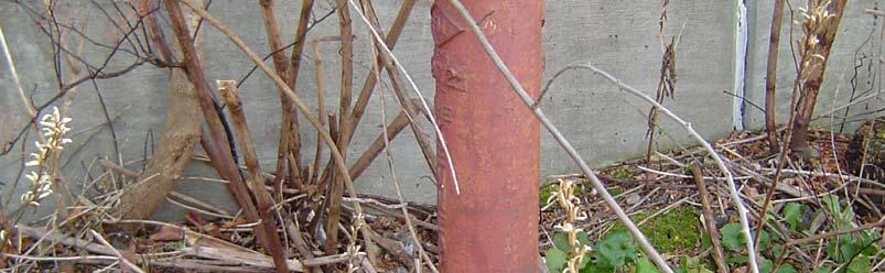
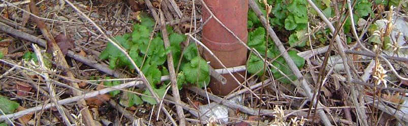
17 Railroad Gate #2B Post Indicator


18 Railroad Flood Gate #1 Gravity Storm Drainage Outlet With Sluice Gate Structure #1


19 Pressure Conduit Storm Drainage Outlet With Sluice Gate Structure #11 Gravity Storm Drainage Outlet With Sluice Gate Structure #10


20 Force Main Discharge Pipes From the Division Street Pumping Station Sanitary Sewer Pipes With Sluice Gate Structure #8


21 Sanitary Sewer Pipes With Sluice Gate Structure #7 Railroad Flood Gate #4

22 Sanitary Sewer Pipe With Sluice Gate Structure #5 (Vegetation has been cleared)
23 Ansonia WPCA Gate Valve Replacement
ENGINEERING REPORT STRUCTURAL STABILITY ANALYSIS FLOODWALLS. HOUSATONIC RIVER and NAUGATUCK RIVER FLOOD PROTECTION PROJECTS SECTION 1
 ENGINEERING REPORT STRUCTURAL STABILITY ANALYSIS FLOODWALLS HOUSATONIC RIVER and NAUGATUCK RIVER FLOOD PROTECTION PROJECTS SECTION 1 ANSONIA and DERBY, CONNECTICUT December 2010 MMI #1560-119 and #3118-03
FEMA and Levees Levee Accreditation Reviews Proposed Changes to the FEMA Levee Policy
 Agenda FEMA and Levees Levee Accreditation Reviews Proposed Changes to the FEMA Levee Policy Page 2 FEMA and Levees FEMA and Levees FEMA does NOT own or operate any levees Establishment of appropriate
Regulation 18 August 2009 NO Operations and Maintenance LEVEE ENCROACHMENT STANDARDS AND PROCEDURES
 CENWP-EC DEPARTMENT OF THE ARMY PDR 30-2-5 Portland District, Corps of Engineers (Draft) P.O. Box 2946 Portland, Oregon 97208 Regulation 8 August 2009 NO. 30-2-5 Operations and Maintenance LEVEE ENCROACHMENT
Freight Street Development Strategy
 Freight Street Development Strategy Appendix B: Naugatuck River Floodplain Analysis Freight Street Development Strategy DECEMBER 2017 Page B-1 1.0 NAUGATUCK RIVER FLOODPLAIN AT FREIGHT STREET 1.1 Watershed
LOS ANGELES RIVER 7 LEVEE SYSTEM LOS ANGELES COUNTY, CALIFORNIA NLD SYSTEM ID #
 LOS ANGELES COUNTY, CALIFORNIA NLD SYSTEM ID # 3805010078 PERIODIC INSPECTION REPORT NO 1 GENERALIZED EXECUTIVE SUMMARY FINAL SYSTEM RATING: UNACCEPTABLE FINAL RATING DATE: AUGUST 26, 2015 PERIODIC INSPECTION
VENTURA RIVER 1 LEVEE SYSTEM VENTURA COUNTY, CALIFORNIA NLD ID #
 VENTURA RIVER 1 LEVEE SYSTEM VENTURA COUNTY, CALIFORNIA NLD ID # 380510086 PERIODIC INSPECTION REPORT NO 1 GENERALIZED EXECUTIVE SUMMARY 8 JUNE 2012 FINAL RATING: MINIMALLY ACCEPTABLE FINAL RATING DATE:
SAN GABRIEL RIVER/SAN JOSE CREEK 1 LEVEE SYSTEM LOS ANGELES COUNTY, CALIFORNIA NLD SYSTEM ID #
 SAN GABRIEL RIVER/SAN JOSE CREEK 1 LEVEE SYSTEM LOS ANGELES COUNTY, CALIFORNIA NLD SYSTEM ID # 3805010052 PERIODIC INSPECTION REPORT NO 1 GENERALIZED EXECUTIVE SUMMARY FINAL SYSTEM RATING: MINIMALLY ACCEPTABLE
SANTA ANA RIVER/ SAN TIMOTEO CREEK 1 LEVEE SYSTEM SAN BERNARDINO COUNTY, CALIFORNIA NLD SYSTEM ID #
 SANTA ANA RIVER/ SAN TIMOTEO CREEK 1 LEVEE SYSTEM SAN BERNARDINO COUNTY, CALIFORNIA NLD SYSTEM ID # 3805030015 PERIODIC INSPECTION REPORT NO. 1 GENERALIZED EXECUTIVE SUMMARY FINAL SYSTEM RATING: UNACCEPTABLE
DOWNTOWN SHALL NOT FLOOD AGAIN
 DOWNTOWN SHALL NOT FLOOD AGAIN Robert C. Steidel**, Robert Stone**, Lin Liang*, Edward J. Cronin*, Federico E. Maisch* *Greeley and Hansen LLC 2116 W Laburnum Avenue, Suite 100 Richmond, Virginia 23227
SAN GABRIEL RIVER/COYOTE CREEK 2 LEVEE SYSTEM LOS ANGELES AND ORANGE COUNTIES, CALIFORNIA NLD SYSTEM ID #
 SAN GABRIEL RIVER/COYOTE CREEK 2 LEVEE SYSTEM LOS ANGELES AND ORANGE COUNTIES, CALIFORNIA NLD SYSTEM ID # 3805010035 PERIODIC INSPECTION REPORT NO 1 GENERALIZED EXECUTIVE SUMMARY FINAL SYSTEM RATING: UNACCEPTABLE
LOS ANGELES RIVER/ COMPTON CREEK 2 LEVEE SYSTEM LOS ANGELES COUNTY, CALIFORNIA NLD SYSTEM ID #
 LOS ANGELES RIVER/ COMPTON CREEK 2 LEVEE SYSTEM LOS ANGELES COUNTY, CALIFORNIA NLD SYSTEM ID # 3805010033 PERIODIC INSPECTION REPORT NO. 2 GENERALIZED EXECUTIVE SUMMARY FINAL SYSTEM RATING: UNACCEPTABLE
Analyzing Flood Risk from the I&M Canal s Non-Levee Embankments A Modified Application of FEMA s Natural Valley Procedure
 Analyzing Flood Risk from the I&M Canal s Non-Levee Embankments A Modified Application of FEMA s Natural Valley Procedure Tiffany Coleman, PE Senior Project Engineer Stantec/STARR September 10, 2015 How
LOS ANGELES RIVER/COMPTON CREEK 2 LEVEE SYSTEM LOS ANGELES COUNTY, CALIFORNIA NLD SYSTEM ID #
 LOS ANGELES RIVER/COMPTON CREEK 2 LEVEE SYSTEM LOS ANGELES COUNTY, CALIFORNIA NLD SYSTEM ID # 3805010033 PERIODIC INSPECTION REPORT NO 1 GENERALIZED EXECUTIVE SUMMARY FINAL SYSTEM RATING: UNACCEPTABLE
American Water Resources Association Philadelphia Metropolitan Area Section
 American Water Resources Association Philadelphia Metropolitan Area Section Levee Evaluation and Certification under the NFIP November 18, 2010 Insert picture(s) here Agenda Background and Overview Flood
LOS ANGELES RIVER/COMPTON CREEK 2 LEVEE SYSTEM LOS ANGELES COUNTY, CALIFORNIA NLD SYSTEM ID #
 LOS ANGELES RIVER/COMPTON CREEK 2 LEVEE SYSTEM LOS ANGELES COUNTY, CALIFORNIA NLD SYSTEM ID # 3805010033 PERIODIC INSPECTION REPORT NO 1 GENERALIZED EXECUTIVE SUMMARY FINAL SYSTEM RATING: UNACCEPTABLE
Port of Camas/Washougal Levee Recertification and Engineering Analysis Request for Proposal May 3, 2011
 I. Project Summary As part of their Map Modernization Program, FEMA has initiated a countywide Flood Insurance Study (FIS) and Digital Flood Insurance Rate Map (DFIRM) for the Port of Camas/Washougal.
SAN GABRIEL RIVER 1 LEVEE SYSTEM LOS ANGELES AND ORANGE COUNTIES, CALIFORNIA NLD SYSTEM ID #
 LOS ANGELES AND ORANGE COUNTIES, CALIFORNIA NLD SYSTEM ID # 3805010031 PERIODIC INSPECTION REPORT NO 1 GENERALIZED EXECUTIVE SUMMARY FINAL SYSTEM RATING: UNACCEPTABLE FINAL RATING DATE: MARCH 15, 2013
ARKANSAS & LOUISIANA LEVEE AND DRAINAGE DISTRICTS MEETINGS
 ARKANSAS & LOUISIANA LEVEE AND DRAINAGE DISTRICTS MEETINGS Rodney Nordby Vicksburg District Red River Projects Office Bossier City, LA. 25-26 January 2017 AGENDA - Types of Inspections - Levee Maintenance
SECTION 3 DRAINAGE. 3-1 General. 3-2 Drainage Ordinances and Legal Requirements
 SECTION 3 DRAINAGE 3-1 General All Drainage plans for proposed development shall be prepared by a Professional Engineer registered in Virginia, except as noted below. Further, their seal and signature
Report. Inflow Design Flood Control System Plan St. Clair Power Plant St. Clair, Michigan. DTE Energy Company One Energy Plaza, Detroit, MI
 Report Inflow Design Flood Control System Plan St. Clair Power Plant St. Clair, Michigan DTE Energy Company One Energy Plaza, Detroit, MI October 14, 2016 NTH Project No. 62-160047-04 NTH Consultants,
INDIAN BEND WASH 2 LEVEE SYSTEM MARICOPA COUNTY, ARIZONA NLD SYSTEM ID #
 INDIAN BEND WASH 2 LEVEE SYSTEM MARICOPA COUNTY, ARIZONA NLD SYSTEM ID # 3805020008 PERIODIC INSPECTION REPORT NO. 1 GENERALIZED EXECUTIVE SUMMARY FINAL SYSTEM RATING: MINIMALLY ACCEPTABLE FINAL RATING
SAN LUIS REY RIVER 3 LEVEE SYSTEM SAN DIEGO COUNTY, CALIFORNIA NLD SYSTEM ID #
 SAN DIEGO COUNTY, CALIFORNIA NLD SYSTEM ID # 3805010012 PERIODIC INSPECTION REPORT NO. 1 GENERALIZED EXECUTIVE SUMMARY FINAL SYSTEM RATING: UNACCEPTABLE FINAL RATING DATE: DECEMBER 15, 2017 PERIODIC INSPECTION
Kansas Levee Certifications Assessments, Findings and Challenges. APWA Congress Denver, Co - Sept 18, 2011
 Kansas Levee Certifications Assessments, Findings and Challenges APWA Congress Denver, Co - Sept 18, 2011 Introductions Presenters Doug Danaher, PE, CFM Wilson and Company Joe File, PE, CFM AMEC Brian
Chapter A-13 STRUCTURAL ANALYSIS ARGENTINE RAISE
 Kansas Citys, Missouri and Kansas Flood Damage Reduction Feasibility Study (Section 216 Review of Completed Civil Works Projects) Engineering Appendix to the Interim Feasibility Report Chapter A-13 STRUCTURAL
MILL CREEK LEVEE SYSTEM SAN BERNARDINO COUNTY, CALIFORNIA NLD SYSTEM ID #
 SAN BERNARDINO COUNTY, CALIFORNIA NLD SYSTEM ID # 3805010056 PERIODIC INSPECTION REPORT NO 1 GENERALIZED EXECUTIVE SUMMARY FINAL SYSTEM RATING: MINIMALLY ACCEPTABLE FINAL RATING DATE: SEPTEMBER 23, 2013
Exhibit C Maintenance and Operations Plan For the Concrete Floodwall and Reinforced Concrete Box Culvert Beneath Cape May Drive
 Exhibit C Maintenance and Operations Plan For the Concrete Floodwall and Reinforced Concrete Box Culvert Beneath Cape May Drive A. Statement of Purpose: Certain homes within the Harbor Lights development
Asst.Prof.Dr. Jaafar S. Maatooq. 1 st Semester HYDRAULIC STRUCTUER, KINDS & FUNCTIONS 1 of 26
 1 st Semester HYDRAULIC STRUCTUER, KINDS & FUNCTIONS 1 of 26 1 st Semester HYDRAULIC STRUCTUER, KINDS & FUNCTIONS 2 of 26 Water is often more useful to people when it is properly controlled, conveyed,
Report. Inflow Design Flood Control System Plan Belle River Power Plant East China, Michigan. DTE Energy Company One Energy Plaza, Detroit, MI
 Report Inflow Design Flood Control System Plan Belle River Power Plant East China, Michigan DTE Energy Company One Energy Plaza, Detroit, MI October 14, 2016 NTH Project No. 62-160047-04 NTH Consultants,
SAN GABRIEL RIVER 1 LEVEE SYSTEM LOS ANGELES COUNTY, CALIFORNIA NLD SYSTEM ID #
 LOS ANGELES COUNTY, CALIFORNIA NLD SYSTEM ID # 3805010031 PERIODIC INSPECTION REPORT NO. 2 GENERALIZED EXECUTIVE SUMMARY FINAL SYSTEM RATING: MINIMALLY ACCEPTABLE FINAL RATING DATE: APRIL 19, 2017 PERIODIC
CONSTRUCTION PLAN CHECKLIST
 CONSTRUCTION PLAN CHECKLIST The design engineer is responsible for ensuring that plans submitted for city review are in accordance with this checklist. It is requested that the executed checklist be submitted
DESIGN & CONSTRUCTION BUDGET AND FIVE YEAR CIP PROJECT SUMMARY - ZONE 1 FISCAL YEARS THROUGH
 RIVERSIDE COUNTY FLOOD CONTROL AND WATER CONSERVATION DISTRICT DESIGN & CONSTRUCTION BUDGET AND FIVE YEAR CIP PROJECT SUMMARY - ZONE 1 FISCAL YEARS 2017-18 THROUGH 2021-22 Project Number Stg No. Project
Levee Improvement District No. 19 System Review Phase 1 Fort Bend County, Texas
 Levee Improvement District No. 19 Fort Bend County, Texas Prepared for: Fort Bend County Levee Improvement District No. 19 202 Century Square Blvd. Sugar Land, Texas 77478 Submitted by: Aptim Environmental
CHAPTER 17: STORM SEWER STANDARDS Introduction Administration Standards 17.1
 CHAPTER 17: STORM SEWER STANDARDS 17.00 Introduction 17.01 Administration 17.02 Standards 17.1 17.00 INTRODUCTION The purpose of this chapter is to provide guidance for the design and construction of storm
Division 33. Utilities
 See Section 32 for requirements on Utility Plan Preparation. 33 10 00. Water Utilities 33 11 00. Water Utility Distribution Piping 1. All underground pipe material, 4 inch diameter and larger shall be
APPENDIX A. Hydraulic Investigations: Cascade Mall at Burlington
 APPENDIX A m SUMMARY REPORT FOR E.I.S. Hydraulic Investigations: Cascade Mall at Burlington July 12, 1982 John E. Norman, P.E. 14779 Northeast 32nd, #A201 Bellevue, WA 98007 (206) 882-1767 92 General A
PAPERWORK REDUCTION ACT A. GENERAL
 U.S. DEPARTMENT OF HOMELAND SECURITY - FEDERAL EMERGENCY MANAGEMENT AGENCY RIVERINE STRUCTURES FORM O.M.B No. 1660-0016 Expires: 12/31/2010 PAPERWORK REDUCTION ACT Public reporting burden for this form
TOWN OF MANCHESTER PLANNING AND ZONING COMMISSION Subdivision Application Minimum Submission Requirements
 TOWN OF MANCHESTER PLANNING AND ZONING COMMISSION Subdivision Application Minimum Submission Requirements This checklist is to be completed and submitted with all Subdivision Applications. The Town reserves
COYOTE CREEK 3 LEVEE SYSTEM LOS ANGELES COUNTY AND ORANGE COUNTY, CALIFORNIA NLD ID #
 LOS ANGELES COUNTY AND ORANGE COUNTY, CALIFORNIA NLD ID # 3805010025 PERIODIC INSPECTION REPORT NO 1 GENERALIZED EXECUTIVE SUMMARY SEPTEMBER 2012 FINAL RATING: MINIMALLY ACCEPTABLE FINAL RATING DATE: 19
4. ACTIONS DURING HIGH WATER EVENTS
 4. ACTIONS DURING HIGH WATER EVENTS This chapter provides sample framework that you could use as a starting point as you develop your community s flood response plan, as described in Chapter 3. The chapter
LOS ANGELES RIVER/RIO HONDO DIVERSION 2 LEVEE SYSTEM LOS ANGELES COUNTY, CALIFORNIA NLD SYSTEM ID #
 LOS ANGELES RIVER/RIO HONDO DIVERSION 2 LEVEE SYSTEM LOS ANGELES COUNTY, CALIFORNIA NLD SYSTEM ID # 3805010047 PERIODIC INSPECTION REPORT NO 1 GENERALIZED EXECUTIVE SUMMARY FINAL SYSTEM RATING: UNACCEPTABLE
Data Collection Report draft
 Data Collection Report draft City of Houston, Minnesota Houston Levee Certification Phase I Report prepared by June 2, 2015 DATA COLLECTION REPORT PHASE I DATA COLLECTION AND REVIEW HOUSTON LEVEE CERTIFICATION
Current / Recent Construction Projects
 Zone 1 Report to the Zone Commissioners By Jason Uhley, General Manager-Chief Engineer November 2017 Current / Recent Construction Projects Monroe MDP - Monroe Channel Stage 4 (1-8-00071-04) In June 2017,
INFLOW DESIGN FLOOD CONTROL SYSTEM PLAN 40 C.F.R. Part PLANT MCINTOSH ASH POND 1 GEORGIA POWER COMPANY
 INFLOW DESIGN FLOOD CONTROL SYSTEM PLAN 40 C.F.R. Part 257.82 PLANT MCINTOSH ASH POND 1 GEORGIA POWER COMPANY EPA s Disposal of Coal Combustion Residuals from Electric Utilities Final Rule (40 C.F.R. Part
CHAPTER 7. San Dieguito River Flooding Adaptation
 CHAPTER 7 San Dieguito River Flooding Adaptation This chapter includes a range of adaptation measures to address vulnerabilities from flooding along the San Dieguito River, including the river valley,
SANTA ANA RIVER 1 LEVEE SYSTEM (UPSTREAM REACH) ORANGE COUNTY, CALIFORNIA NLD SYSTEM ID #
 ORANGE COUNTY, CALIFORNIA NLD SYSTEM ID #") SANTA ANA RIVER 1 LEVEE SYSTEM (UPSTREAM REACH) ORANGE COUNTY, CALIFORNIA NLD SYSTEM ID # 3805010039 PERIODIC INSPECTION REPORT NO. 1 GENERALIZED EXECUTIVE SUMMARY FINAL SYSTEM RATING: MINIMALLY ACCEPTABLE
SANTA ANA RIVER 1 LEVEE SYSTEM (UPSTREAM REACH) ORANGE COUNTY, CALIFORNIA NLD SYSTEM ID # 3805010039 PERIODIC INSPECTION REPORT NO. 1 GENERALIZED EXECUTIVE SUMMARY FINAL SYSTEM RATING: MINIMALLY ACCEPTABLE
Design Documentation Report
 September 2014 Design Documentation Report Fargo-Moorhead Flood Risk Management Project El Zagal Area Flood Risk Management Phase 1 Engineering and Design Phase 65% SUBMITTAL Table of Contents Abstract...
CHAPTER 7. San Dieguito River Flooding Adaptation
 CHAPTER 7 San Dieguito River Flooding Adaptation This chapter includes a range of adaptation measures to address vulnerabilities from flooding along the San Dieguito River, including the river valley,
Coal Combustion Residuals Unit Structural Stability Assessment
 Coal Combustion Residuals Unit Structural Stability Assessment Virginia Electric and Power Company Chesterfield Power Station Upper (East) Pond Chesterfield County, Virginia GAI Project Number: C1500035.00
2. DEFINITIONS. American Association of State Highway and Transportation Officials.
 2. DEFINITIONS 2.010 Definitions [See Amendment 2] In addition to words and terms that may be defined elsewhere in this manual, the following words and terms shall have the meanings defined below: AASHTO:
INFLOW DESIGN FLOOD CONTROL SYSTEM PLAN PLANT GASTON GYPSUM POND ALABAMA POWER COMPANY
 INFLOW DESIGN FLOOD CONTROL SYSTEM PLAN PLANT GASTON GYPSUM POND ALABAMA POWER COMPANY Section 257.82 of EPA s regulations requires the owner or operator of an existing or new CCR surface impoundment or
Metropolitan St. Louis Sewer District Statement of Policy for Maintenance of Stormwater Sewer Systems
 Metropolitan St. Louis Sewer District Statement of Policy for Maintenance of Stormwater Sewer Systems 1.0 Introduction Adequate drainage in the Metropolitan St. Louis area is necessary to preserve and
COYOTE CREEK 3 LEVEE SYSTEM LOS ANGELES COUNTY AND ORANGE COUNTY, CALIFORNIA NLD SYSTEM ID #
 LOS ANGELES COUNTY AND ORANGE COUNTY, CALIFORNIA NLD SYSTEM ID # 3805010025 PERIODIC INSPECTION REPORT NO. 2 GENERALIZED EXECUTIVE SUMMARY FINAL SYSTEM RATING: MINIMALLY ACCEPTABLE FINAL RATING DATE: MARCH
Chapter 11 Culverts and Bridges
 Chapter 11 Culverts and Bridges Contents 1.0 Introduction... 1 2.0 General Design... 1 2.1 Design Criteria... 1 2.2 Design Flows... 1 2.3 Permitting and Regulations... 1 2.4 Aesthetics and Safety... 2
4. FISH PASSAGE CONCEPTS
 Feasibility Study for Restoration of Titlow Lagoon Fish Passage South Puget Sound Salmon Enhancement Group 4. FISH PASSAGE CONCEPTS Fish passage could be improved by rehabilitating the existing fish passage,
INFLOW DESIGN FLOOD CONTROL SYSTEM PLAN 40 C.F.R. PART PLANT YATES ASH POND 3 (AP-3) GEORGIA POWER COMPANY
 GEORGIA POWER COMPANY") INFLOW DESIGN FLOOD CONTROL SYSTEM PLAN 40 C.F.R. PART 257.82 PLANT YATES ASH POND 3 (AP-3) GEORGIA POWER COMPANY EPA s Disposal of Coal Combustion Residuals from Electric Utilities Final Rule (40 C.F.R.
INFLOW DESIGN FLOOD CONTROL SYSTEM PLAN 40 C.F.R. PART 257.82 PLANT YATES ASH POND 3 (AP-3) GEORGIA POWER COMPANY EPA s Disposal of Coal Combustion Residuals from Electric Utilities Final Rule (40 C.F.R.
Maintaining Your Levee
 Maintaining Your Levee North Kansas City Levee District Case Study Leon J. Staab, P.E. KC Urban Stormwater Conference January 23, 2016 I n t r o d u c t i o n North Kansas City Levee Unit Constructed in
CRYSTAL LAKE FLOODING STUDY EXECUTIVE SUMMARY
 Project #08223 CRYSTAL LAKE FLOODING STUDY EXECUTIVE SUMMARY PREPARED FOR: City of Crystal Lake 100 West Woodstock Street Crystal Lake, Illinois 60014 FEBRUARY 11, 2009 26575 W. COMMERCE DRIVE, SUITE 601,
APPENDIX F: DRAINAGE AND STORMWATER MANAGEMENT
 APPENDIX F: DRAINAGE AND STORMWATER MANAGEMENT Downtown Ottawa Transit Tunnel: Tunney s Pasture to Blair Station via a Downtown LRT Tunnel Prepared for: City of Ottawa 110 Laurier Avenue West Ottawa, ON
PRELIMINARY DRAINAGE REPORT NEWCASTLE FIRE STATION OLD STATE HIGHWAY
 PRELIMINARY DRAINAGE REPORT FOR THE NEWCASTLE FIRE STATION OLD STATE HIGHWAY PREPARED FOR THE NEWCASTLE FIRE PROTECTION DISTRICT JULY 2014 BY ROSEVILLE DESIGN GROUP, INC. ROSEVILLE DESIGN GROUP, Inc Established
3. FLOOD PREPAREDNESS
 3. FLOOD PREPAREDNESS Flood fighting is an art, and can be extremely difficult to execute. There is no absolute method that one can apply to guarantee success. However, failure to react in a timely manner
THE STUDY ON INTEGRATED URBAN DRAINAGE IMPROVEMENT FOR MELAKA AND SUNGAI PETANI IN MALAYSIA FINAL REPORT
 THE GOVERNMENT OF MALAYSIA PRIME MINISTER S DEPARTMENT ECONOMIC PLANNING UNIT THE STUDY ON INTEGRATED URBAN DRAINAGE IMPROVEMENT FOR MELAKA AND SUNGAI PETANI IN MALAYSIA FINAL REPORT VOL. 5: TECHNICAL
USACE SPL Levee Safety Program Driving Risk Down NEVADA
 Los Angeles District COE Jody Fischer P.E. Levee Safety Program Manager Patti Sexton P.E. VP Tetra Tech OREGON USACE SPL Levee Safety Program Driving Risk Down NEVADA IDAHO WYOMING A Presentation for the
DESIGN GRADING AND EROSION CONTROL A. Slope Criteria
 Section 5. DESIGN GRADING AND EROSION CONTROL A. Slope Criteria Earthen slopes shall conform to the following: Maximum slope should not be steeper than 6:1 (horizontal to vertical) unless protected from
TABLE OF CONTENTS 2 TITLE PAGE 1
 TABLE OF CONTENTS TITLE PAGE 1 TABLE OF CONTENTS 2 1.0 INTRODUCTION 3 2.0 STORMWATER MANAGEMENT 3 3.0 STORMWATER MANAGEMENT PRACTICES 4 4.0 SANITARY SEWERAGE 5 5.0 WATER DISTRIBUTION 6 6.0 CONCLUSION 7
OVERHEAD SEWER REIMBURSEMENT PROGRAM
 Village of Lombard OVERHEAD SEWER REIMBURSEMENT PROGRAM IN ORDER TO QUALIFY FOR THE VILLAGE OF LOMBARD OVERHEAD SEWER COST SHARING PROGRAM: The perimeter drain tile and any other source of storm water
6 STORMWATER IMPROVEMENTS
 6 STORMWATER IMPROVEMENTS 6.01 General Requirements a. In addition to the standards contained in this, the design of stormwater systems is also governed by several ordinances and regulations. (1) Projects
III. INVENTORY OF EXISTING FACILITIES
 III. INVENTORY OF EXISTING FACILITIES Within the Growth Management Boundary, the existing storm drainage facilities are largely associated with development that has historically occurred in the ten drainage
INFLOW DESIGN FLOOD CONTROL SYSTEM PLAN PLANT GREENE COUNTY ASH POND ALABMA POWER COMPANY
 INFLOW DESIGN FLOOD CONTROL SYSTEM PLAN PLANT GREENE COUNTY ASH POND ALABMA POWER COMPANY Section 257.82 of EPA s regulations requires the owner or operator of an existing or new CCR surface impoundment
SAN GABRIEL RIVER/ COYOTE CREEK 2 LEVEE SYSTEM LOS ANGELES COUNTY, CALIFORNIA NLD SYSTEM ID #
 SAN GABRIEL RIVER/ COYOTE CREEK 2 LEVEE SYSTEM LOS ANGELES COUNTY, CALIFORNIA NLD SYSTEM ID # 3805010031 PERIODIC INSPECTION REPORT NO. 2 GENERALIZED EXECUTIVE SUMMARY FINAL SYSTEM RATING: MINIMALLY ACCEPTABLE
STORM DRAINAGE DESIGN MANUAL
 Appendix I STORM DRAINAGE DESIGN MANUAL by: SUNGATE DESIGN GROUP, P.A. GEN ERAL DESIGN STAN DARDS AN D POLICIES 1. STREET AND LOCAL DRAINAGE Discharge estimates for specified design storms shall be calculated
APPENDIX J-3. Orcem Stormwater Management and Treatment Facilities Design Summary
 APPENDIX J-3 Orcem Stormwater Management and Treatment Facilities Design Summary Stormwater Management & Treatment Facilities Design Summary INTRODUCTION KPFF Consulting Engineers has compiled this report
Dawson County Public Works 25 Justice Way, Suite 2232, Dawsonville, GA (706) x 42228
 x 42228") Dawson County Public Works 25 Justice Way, Suite 2232, Dawsonville, GA 30534 (706) 344-3500 x 42228 DAWSON COUNTY STORM WATER REVIEW CHECKLIST Project Name: Property Address: Engineer: Fax #/Email: Date:
Dawson County Public Works 25 Justice Way, Suite 2232, Dawsonville, GA 30534 (706) 344-3500 x 42228 DAWSON COUNTY STORM WATER REVIEW CHECKLIST Project Name: Property Address: Engineer: Fax #/Email: Date:
6 STORMWATER IMPROVEMENTS
 6 STORMWATER IMPROVEMENTS 6.01 General Requirements a. In addition to the standards contained in this, the design of stormwater systems is also governed by several ordinances and regulations. (1) Projects
AGUA FRIA RIVER 5 LEVEE SYSTEM MARICOPA COUNTY, ARIZONA NLD SYSTEM ID #
 AGUA FRIA RIVER 5 LEVEE SYSTEM MARICOPA COUNTY, ARIZONA NLD SYSTEM ID # 3805020001 PERIODIC INSPECTION REPORT NO. 1 GENERALIZED EXECUTIVE SUMMARY FINAL SYSTEM RATING: MINIMALLY ACCEPTABLE FINAL RATING
PROGRAM OVERVIEW... 3 REAR YARD DRAINAGE COST SHARE PROGRAM... 3 REAR YARD DRAINAGE PROGRAM PROCEDURE... 4 RULES AND RESTRICTIONS...
 Village of Franklin Park Cost Share Program The Village of Franklin Park Cost Share Program includes a Rear Yard Drainage Program and an Overhead Sewer Program. Both programs have been created to assist
UNIVERSITY OF OREGON NORTH CAMPUS CONDITIONAL USE PERMIT PROJECT Draft Conditional Use Permit Stormwater, Sanitary Sewer, and Water Analysis Report
 UNIVERSITY OF OREGON NORTH CAMPUS CONDITIONAL USE PERMIT PROJECT Draft Conditional Use Permit Stormwater, Sanitary Sewer, and Water Analysis Report Prepared for: Cameron McCarthy Landscape Architects LLP
Appendix G Preliminary Hydrology Study
 Appendix G Preliminary Hydrology Study Preliminary Hydrology Study VESTING TTM 72608 Long Beach, CA Prepared for: The Long Beach Project, LLC 888 San Clemente, Suite 100 New Port Beach, CA May 28, 2014
Chapter 11 Culverts and Bridges
 Chapter 11 Table of Contents 11-1 Introduction... 1 11-2 General Design... 1 11-2-1 Design Criteria... 1 11-2-2 Design Flows... 1 11-2-3 Permitting and Regulations... 2 11-2-4 Aesthetics and Safety...
Chapter 11 Culverts and Bridges
 Chapter 11 Table of Contents 11-1 Introduction... 1 11-2 General Design... 1 11-2-1 Design Criteria... 1 11-2-2 Design Flows... 1 11-2-3 Permitting and Regulations... 2 11-2-4 Aesthetics and Safety...
STORM DRAINAGE CHAPTER 11
 CHAPTER 11 STORM DRAINAGE SECTION 11 GENERAL 11.1 Scope. The provisions of this chapter shall govern the materials, design, construction and installation of storm drainage. 11.2 Where required. All roofs,
TABLE OF CONTENTS PART III - MINIMUM DESIGN STANDARDS Section 105 DRAINAGE SYSTEM DESIGN SPECIFICATIONS AND SCOPE 105.1
 TABLE OF CONTENTS PART III - MINIMUM DESIGN STANDARDS Section 105 DRAINAGE SYSTEM DESIGN SECTION TITLE PAGE 105.1. SPECIFICATIONS AND SCOPE 105.1 105.2. METHODS OF ANALYSIS 105.1 105.2.1. Rational Method
HYDROLOGIC-HYDRAULIC STUDY ISABELLA OCEAN RESIDENCES ISLA VERDE, CAROLINA, PR
 HYDROLOGIC-HYDRAULIC STUDY ISABELLA OCEAN RESIDENCES ISLA VERDE, CAROLINA, PR 1 INTRODUCTION 1.1 Project Description and Location Isabella Ocean Residences is a residential development to be constructed
POST CLOSURE PLAN. CFR (d) Pond 1. Clinch Power Plant Russell County, West Virginia. November Prepared for: Appalachian Power Company
 Pond 1. Clinch Power Plant Russell County, West Virginia. November Prepared for: Appalachian Power Company") POST CLOSURE PLAN CFR 257.104(d) Pond 1 Clinch Power Plant Russell County, West Virginia November 2016 Prepared for: Appalachian Power Company Prepared by: Amec Foster Wheeler Environment & Infrastructure,
POST CLOSURE PLAN CFR 257.104(d) Pond 1 Clinch Power Plant Russell County, West Virginia November 2016 Prepared for: Appalachian Power Company Prepared by: Amec Foster Wheeler Environment & Infrastructure,
Attachment H: Engineering Documentation
 Attachment H: Engineering Documentation Part 2: Hydrologic and Hydraulic Consistency Worksheet Inland Water Resources Division Permit Activities This worksheet has four sections; only complete the section(s)
Description. Installation and Implementation Requirements
 Earth Dike SC-6 Source: Caltrans Construction Site Best Management Practices Manual, 2003. Description Structure that prevents erosion by intercepting, diverting, and conveying surface run-on (storm water
BMP FACT SHEET DF-1 HOA Annual Self-Certification Report
 PURPOSE: Public and privately owned and maintained stormwater conveyance systems collect and transport urban runoff and storm water that may contain certain pollutants. These pollutants may accumulate
Application for a Dam Permit Ash Basin No. 1
 Application for a Dam Permit Ash Basin No. 1 for the Sunbury Generating Station Shamokin Dam, Pennsylvania submitted to Commonwealth of Pennsylvania Department of Environmental Protection Bureau of Waterways
4.4.6 Underground Detention
 4.4.6 Underground Detention Limited Application Water Quality BMP Description: Detention storage located in underground pipe systems or vaults designed to provide water quantity control through detention
STORM WATER ASSET MANAGEMENT PLAN & PROGRAM
 STORM WATER ASSET MANAGEMENT PLAN & PROGRAM City of Walker, MI September 2017 System Goals and Action Plan INTRODUCTION About this Document This document is our Storm Water Asset Management Plan & Program
VISUAL SITE INSPECTION REPORT 2018
 VISUAL SITE INSPECTION REPORT 2018 SOUTHERN INDIANA GAS AND ELECTRIC A. B. BROWN GENERATING STATION TYPE III RESTRICTED WASTE LANDFILL WEST FRANKLIN, IN ATC PROJECT NO. 170LF00614 January 9, 2019 PREPARED
بسم هللا الرحمن الرحيم
 بسم هللا الرحمن الرحيم )ملحقات شبكة الصرف الصحي( Class Sewer Appurtenances- 3 rd Dr. Sataa Al-Bayati (10-11) 1. Manholes They are used for inspection & cleaning. They placed when: 1. Intervals between
ZONING ORDINANCE FOR THE ZONED UNINCORPORATED AREAS ARTICLE 1500 OF PUTNAM COUNTY, WEST VIRGINIA Page 149 ARTICLE 1500 DRAINAGE AND STORM SEWERS
 OF PUTNAM COUNTY, WEST VIRGINIA Page 149 ARTICLE 1500 DRAINAGE AND STORM SEWERS 1500.01 GENERAL REQUIREMENTS 1500.02 NATURE OF STORM WATER FACILITIES 1500.03 DRAINAGE EASEMENTS 1500.04 STORM WATER MANAGEMENT
INITIAL INFLOW DESIGN FLOOD CONTROL SYSTEM PLAN PLANT MCMANUS ASH POND A (AP-1) 40 CFR
 40 CFR") INITIAL INFLOW DESIGN FLOOD CONTROL SYSTEM PLAN PLANT MCMANUS ASH POND A (AP-1) 40 CFR 257.82 EPA s Disposal of Coal Combustion Residuals from Electric Utilities Final Rule (40 C.F.R. Part 257 and Part
INITIAL INFLOW DESIGN FLOOD CONTROL SYSTEM PLAN PLANT MCMANUS ASH POND A (AP-1) 40 CFR 257.82 EPA s Disposal of Coal Combustion Residuals from Electric Utilities Final Rule (40 C.F.R. Part 257 and Part
PART 3 - STANDARDS FOR SEWERAGE FACILITIES DESIGN OF STORM SEWERS
 PART 3 - STANDARDS FOR SEWERAGE FACILITIES 3.3 - DESIGN OF STORM SEWERS 3.301 Design of Storm Sewers A. General Information B. Investigations and Surveys C. Special Projects 3.302 Design Criteria for Storm
BMP Description: The GSWMD will work with NIRPC and local groups to mark existing storm sewer structures.
 Sewer Marking Projects is this The GSWMD will work with NIRPC and local groups to mark existing storm sewer structures. NIRPC By marking the storm sewer structures, it alerts the public that the structures
REQUEST FOR CONSTRUCTION BIDS February 22, 2010
 REQUEST FOR CONSTRUCTION BIDS February 22, 2010 Roaring Branch Channel and Floodplain Restoration Project 1.0 Project Background Roaring Branch (watershed area ~ 41 square miles) flows generally west through
General Rules and Regulations
 General Rules and Regulations City of Hamilton, Ohio Sanitary Sewer Collection and Treatment Revised December 23, 2016 Page 1 of 13 To Our Customers, Sanitary Sewer Collection and Treatment Department
REQUEST FOR CONSTRUCTION BIDS May 23, 2017
 REQUEST FOR CONSTRUCTION BIDS May 23, 2017 Cambridge Greenway Trail / Railroad Bridge Replacement Flood Mitigation Project 1.0 Project Background A former railroad bridge that currently carries the Cambridge