INFLOW DESIGN FLOOD CONTROL SYSTEM PLAN PLANT GASTON GYPSUM POND ALABAMA POWER COMPANY
|
|
|
- Lindsey Small
- 5 years ago
- Views:
Transcription
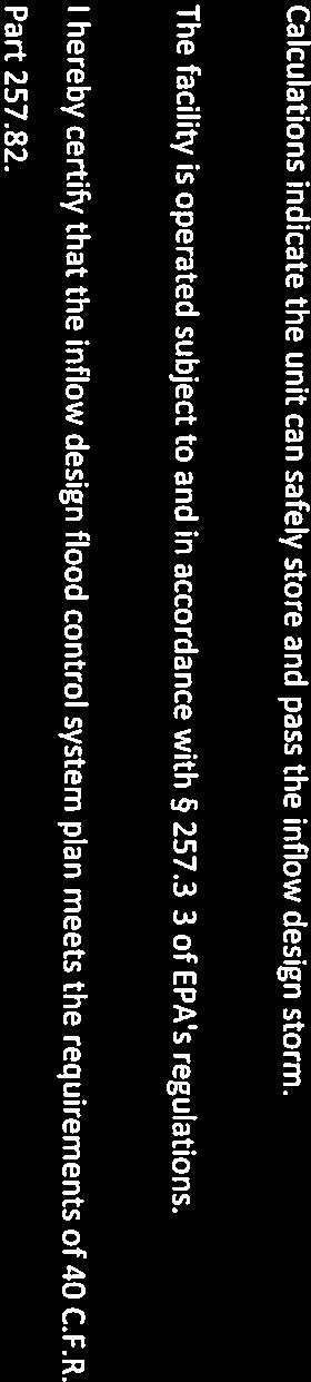
1 INFLOW DESIGN FLOOD CONTROL SYSTEM PLAN PLANT GASTON GYPSUM POND ALABAMA POWER COMPANY Section of EPA s regulations requires the owner or operator of an existing or new CCR surface impoundment or any lateral expansion of a CCR surface impoundment to design, construct, operate and maintain an inflow design flood control system capable of safely managing flow during and following the peak discharge of the specified inflow design flood. The owner or operator also has to prepare a written plan documenting how the inflow flood control system has been designed and constructed to meet the requirements of this section of the rule. The existing CCR surface impoundment referred to as the Plant Gaston Gypsum Pond is located at Alabama Power Company s Plant Gaston. The facility consists of a CCR storage area (Cell 1) and a sedimentation pond. The inflow design flood consists of the rainfall that falls within the limits of the surface impoundment, runoff from approximately 14 acres of adjoining watershed, and a nominal amount (relative to the rainfall) of process flows. Stormwater is temporarily stored within the limits of the surface impoundment and discharged through a stop log riser system connected to a 36 inch discharge pipe that routes discharges to the sedimentation pond. The inflow design flood has been calculated using the Natural Resources Conservation Service method (also known as the Soil Conservation Service (SCS) method) using the 1000 yr storm event required for a Significant hazard potential facility. Runoff curve number data was determined using Table 2 2A from the Urban Hydrology for Small Watersheds (TR 55). Appendix A and B from the TR 55 were used to determine the rainfall distribution methodology. Precipitation values were determined from NOAA s Precipitation Frequency Data Server (Atlas 14). The NRCS provided information on the soil characteristics and hydrologic groups present at the site. It was determined that the hydrological group D should be used to best reflect the characteristics of the soils on site. This information was placed into Hydraflow Hydrographs 2013 and used to generate appropriate precipitation curves, storm basin routing information, and resulting rating curves to evaluate surface impoundment capacity.


2


3
4 1.0 Purpose of Calculation The purpose of this report is to demonstrate the hydraulic capacity of the subject CCR impoundment in order to prepare an inflow design flood control plan as required by the United States Environmental Protection Agency s (EPA) final rule for Disposal of CCR from Electric Utilities (EPA 40 CFR 257). 2.0 Summary of Conclusions A hydrologic and hydraulic model was developed for the Plant Gaston Gypsum Storage Cell to determine the hydraulic capacity of the impoundment. The design storm for the Plant Gaston Gypsum Storage Cell 1 is a 1000-year rainfall event. Southern Company has selected a storm length of 24-hours for all inflow design flood control plans. The results of routing a 1000 year, 24-hour rainfall event through the impoundment are presented in Table 1 below: Plant Gaston Area Gypsum Cell Table 1-Flood Routing Results for Plant Gaston Gypsum Storage Cell Normal Top of Emergency Freeboard* Peak Pool El embankment Spillway (ft) Inflow (ft) El (ft) Crest El (ft) (cfs) 414 to 416** Varies low Peak Water Surface Elevation (ft) Peak Outflow (cfs) N/A *Freeboard is measured from the top of embankment to the peak water surface elevation **Assumed the higher normal pool elevation of in calculations for conservative approach. 3.0 Methodology 3.1 HYDROLOGIC ANALYSES Plant Gaston Gypsum Storage Cell is classified as a significant hazard structure. The design storm for a significant hazard structure is the 1000-year rainfall event. A summary of the design storm parameters and rainfall distribution methodology for these calculations is summarized below in Table 2. Hazard Classification Table 2. Plant Gaston Gypsum Storage Cell Storm Distribution Return Storm Rainfall Total Rainfall Frequency Duration (Inches) Source (years) (hours) Significant NOAA Atlas 14 Storm Distribution SCS Type III
5 The drainage area for Plant Gaston Gypsum Storage Cell was delineated based on LiDAR data acquired for the Plant in Runoff characteristics were developed based on the Soil Conservation Service (SCS) methodologies as outlined in TR-55. An overall SCS curve number for the drainage area was developed based on the National Engineering Handbook Part 630, Chapter 9 which provides a breakdown of curve numbers for each soil type and land use combination. Soil types were obtained from the USGS online soils database. Time of Concentration calculations were developed based on the overland flow method as described in the National Engineering Handbook Part 630, Chapter 15. A table of the pertinent basin characteristics of the Gypsum Cell and Sedimentation Pond is provided below in Tables 3(a) and 3(b). Table 3(a) Plant Gaston Gypsum Storage Cell Hydrologic Information Drainage Basin Area (acres) 43.2 Hydrologic Curve Number, CN 87 Hydrologic Methodology SCS Method Time of Concentration (minutes) 13.9 Hydrologic Software Storm and Sanitary Sewer Analysis, 2013 Autodesk, Inc. Table 3(b) Plant Gaston Gypsum Storage Cell Sediment Pond Hydrologic Information Drainage Basin Area (acres) 11.2 Hydrologic Curve Number, CN 98 Hydrologic Methodology SCS Method Time of Concentration (minutes) 5.0 Hydrologic Software Storm and Sanitary Sewer Analysis, 2013 Autodesk, Inc. Runoff values were determined by importing the characteristics developed above into a hydrologic model in Storm and Sanitary Sewer Analysis (StormNet) by AutoCad Civil 3D, Process flows from Plant Gaston were considered in this analysis. Based on normal plant operations, the gypsum cell receives an additional 3.3 MGD (5.2 cfs) of inflow from the Plant. The gypsum cell receives 1.30 MGD (2.0 cfs) and the Sediment Pond receives 2.0 MGD (3.2 cfs). 3.2 HYDRAULIC ANALYSES Storage values for the Gypsum Cell were determined by developing a stage-storage relationship utilizing contour data for the Gypsum Cell and Sediment Pond. An arrangement of the Gypsum Cell and the Sediment Pond is shown in the attached drainage map in Section 4.5. Gypsum slurry is sluiced into the gypsum cell at the northwest corner into dewatering basins allowing for the settlement of gypsum. Flow from the dewatering basins along with runoff from the cell area during a storm event, flows to the stop log riser located
6 at the east side near the midpoint of the cell. After passing over the stop log weir in the riser it flows thru a 36 inch diameter hdpe pipe to the east into a lined canal which runs to south leading to the sediment basin. Process (sump) flows are added to the Sediment Pond at its northeast corner. The Sediment Pond does have an emergency discharge spillway at the west dike for an extreme storm event, but water levels are managed in the pond to prevent release as the site is a zero discharge system. The outfall from the emergency spillway is to a channel which runs south and discharges in to the Coosa River. A summary of spillway information is presented below in Table 4. Spillway Component Primary Spillway Stop log riser 6 foot square *N/A = Not available Spillway Component Primary Spillway Table 4(a) Plant Gaston Gypsum Cell Spillway Attribute Table US DS Dimension Slope Length Invert El Invert El (ft/ft) (ft) (feet) (feet) Weir L = 3.0 ft., Weir EL Outlet pipe = 36 diameter, HDPE Spillway Capacity (cfs) N/A* Table 4(b) Plant Gaston Gypsum Cell Sediment Pond Spillway Attribute Table US DS Dimension Slope Length Spillway Invert El Invert El (ft/ft) (ft) Capacity (feet) (feet) (cfs) *N/A = Not available Weir L = 3.0 ft., Weir EL Outlet pipe = 36 diameter, HDPE N/A* Based on the spillway attributes listed above, rating curves were developed using Storm and Sanitary Sewer Analysis to determine the pond performance during the design storm. Results are shown in Table SUPPORTING INFORMATION 4.1 CURVE NUMBERS GYPSUM CELL 1
7 4.1.2 SEDIMENTATION POND
8 4.2 STAGE-STORAGE TABLES & CURVES GYPSUM CELL 1:
9 4.2.2 SEDIMENTATION POND
10 4.3 TIME OF CONCENTRATION FORMULAS FOR SHEET FLOW, SHALLOW CONCENTRATED FLOW, CHANNEL FLOW, AND FLOW THRU WATER:
11 4.3.1 GYPSUM CELL SEDIMENTATION POND
12 4.4 RATING CURVES GYPSUM CELL STOP LOG RISER Weir Rating Curve Water Height (ft) Discharge (cfs)
13 4.4.2 GYPSUM CELL RATING CURVES CELL 1 - RUNOFF AND VOLUME VS TIME
14 CELL 1 - INFLOW VS TIME CELL 1 - DEPTH VS TIME
15 CELL 1 STOP LOG RISER - FLOW VS TIME CELL 1 STOP LOG RISER - DEPTH VS TIME

16 4.5 DRAINAGE MAP
INFLOW DESIGN FLOOD CONTROL SYSTEM PLAN PLANT BARRY ASH POND ALABAMA POWER COMPANY
 INFLOW DESIGN FLOOD CONTROL SYSTEM PLAN PLANT BARRY ASH POND ALABAMA POWER COMPANY Section 257.82 of EPA s regulations requires the owner or operator of an existing or new CCR surface impoundment or any
INFLOW DESIGN FLOOD CONTROL SYSTEM PLAN 40 C.F.R. Part PLANT MCINTOSH ASH POND 1 GEORGIA POWER COMPANY
 INFLOW DESIGN FLOOD CONTROL SYSTEM PLAN 40 C.F.R. Part 257.82 PLANT MCINTOSH ASH POND 1 GEORGIA POWER COMPANY EPA s Disposal of Coal Combustion Residuals from Electric Utilities Final Rule (40 C.F.R. Part
INFLOW DESIGN FLOOD CONTROL SYSTEM PLAN 40 C.F.R. PART PLANT BOWEN ASH POND 1 (AP-1) GEORGIA POWER COMPANY
 GEORGIA POWER COMPANY") INFLOW DESIGN FLOOD CONTROL SYSTEM PLAN 40 C.F.R. PART 257.82 PLANT BOWEN ASH POND 1 (AP-1) GEORGIA POWER COMPANY EPA s Disposal of Coal Combustion Residuals from Electric Utilities Final Rule (40 C.F.R.
INFLOW DESIGN FLOOD CONTROL SYSTEM PLAN 40 C.F.R. PART 257.82 PLANT BOWEN ASH POND 1 (AP-1) GEORGIA POWER COMPANY EPA s Disposal of Coal Combustion Residuals from Electric Utilities Final Rule (40 C.F.R.
INFLOW DESIGN FLOOD CONTROL SYSTEM PLAN PLANT GREENE COUNTY ASH POND ALABMA POWER COMPANY
 INFLOW DESIGN FLOOD CONTROL SYSTEM PLAN PLANT GREENE COUNTY ASH POND ALABMA POWER COMPANY Section 257.82 of EPA s regulations requires the owner or operator of an existing or new CCR surface impoundment
INFLOW DESIGN FLOOD CONTROL SYSTEM PLAN 40 C.F.R. PART PLANT DANIEL ASH POND B MISSISSIPPI POWER COMPANY
 INFLOW DESIGN FLOOD CONTROL SYSTEM PLAN 40 C.F.R. PART 257.82 PLANT DANIEL ASH POND B MISSISSIPPI POWER COMPANY EPA s Disposal of Coal Combustion Residuals from Electric Utilities Final Rule (40 C.F.R.
INFLOW DESIGN FLOOD CONTROL SYSTEM PLAN 40 C.F.R. PART PLANT YATES ASH POND B (AP-B ) GEORGIA POWER COMPANY
 GEORGIA POWER COMPANY") INFLOW DESIGN FLOOD CONTROL SYSTEM PLAN 40 C.F.R. PART 257.82 PLANT YATES ASH POND B (AP-B ) GEORGIA POWER COMPANY EPA s Disposal of Coal Combustion Residuals from Electric Utilities Final Rule (40 C.F.R.
INFLOW DESIGN FLOOD CONTROL SYSTEM PLAN 40 C.F.R. PART 257.82 PLANT YATES ASH POND B (AP-B ) GEORGIA POWER COMPANY EPA s Disposal of Coal Combustion Residuals from Electric Utilities Final Rule (40 C.F.R.
INITIAL INFLOW DESIGN FLOOD CONTROL SYSTEM PLAN PLANT MCMANUS ASH POND A (AP-1) 40 CFR
 40 CFR") INITIAL INFLOW DESIGN FLOOD CONTROL SYSTEM PLAN PLANT MCMANUS ASH POND A (AP-1) 40 CFR 257.82 EPA s Disposal of Coal Combustion Residuals from Electric Utilities Final Rule (40 C.F.R. Part 257 and Part
INITIAL INFLOW DESIGN FLOOD CONTROL SYSTEM PLAN PLANT MCMANUS ASH POND A (AP-1) 40 CFR 257.82 EPA s Disposal of Coal Combustion Residuals from Electric Utilities Final Rule (40 C.F.R. Part 257 and Part
INFLOW DESIGN FLOOD CONTROL SYSTEM PLAN 40 C.F.R. PART PLANT YATES ASH POND 3 (AP-3) GEORGIA POWER COMPANY
 GEORGIA POWER COMPANY") INFLOW DESIGN FLOOD CONTROL SYSTEM PLAN 40 C.F.R. PART 257.82 PLANT YATES ASH POND 3 (AP-3) GEORGIA POWER COMPANY EPA s Disposal of Coal Combustion Residuals from Electric Utilities Final Rule (40 C.F.R.
INFLOW DESIGN FLOOD CONTROL SYSTEM PLAN 40 C.F.R. PART 257.82 PLANT YATES ASH POND 3 (AP-3) GEORGIA POWER COMPANY EPA s Disposal of Coal Combustion Residuals from Electric Utilities Final Rule (40 C.F.R.
INITIAL RUN-ON AND RUN-OFF CONTROL PLAN 40 C.F.R. PART 257
 INITIAL RUN-ON AND RUN-OFF CONTROL PLAN 40 C.F.R. PART 257.81 HUFFAKER ROAD (PLANT HAMMOND) PRIVATE INDUSTRIAL LANDFILL (HUFFAKER ROAD LANDFILL) GEORGIA POWER COMPANY EPA s Disposal of Coal Combustion
INITIAL RUN-ON AND RUN-OFF CONTROL PLAN 40 C.F.R. PART 257
 INITIAL RUN-ON AND RUN-OFF CONTROL PLAN 40 C.F.R. PART 257.81 PLANT BOWEN PRIVATE INDUSTRY SOLID WASTE DISPOSAL FACILITY (ASH LANDFILL) GEORGIA POWER COMPANY EPA s Disposal of Coal Combustion Residuals
RUN-ON AND RUN-OFF CONTROL PLAN 40 C.F.R. PART PLANT DANIEL NORTH ASH MANAGEMENT UNIT MISSISSIPPI POWER COMPANY
 RUN-ON AND RUN-OFF CONTROL PLAN 40 C.F.R. PART 257.81 PLANT DANIEL NORTH ASH MANAGEMENT UNIT MISSISSIPPI POWER COMPANY EPA s Disposal of Coal Combustion Residuals from Electric Utilities Final Rule (40
Run-on and Run-off Control System Plan
 Run-on and Run-off Control System Plan For Compliance with the Coal Combustion Residuals Rule (40 CFR 257.81) Pawnee Station CCR Landfill Public Service Company of Colorado Denver, Colorado October 17,
HISTORY OF CONSTRUCTION 40 CFR (c)(1)(i) (xii) PLANT HAMMOND ASH POND (AP 2) GEEORGIA POWER COMPANY
(1)(i) (xii) PLANT HAMMOND ASH POND (AP 2) GEEORGIA POWER COMPANY") HISTORY OF CONSTRUCTION 40 CFR 257.73(c)(1)(i) (xii) PLANT HAMMOND ASH POND (AP 2) GEEORGIA POWER COMPANY (i) Site Name and Ownership Information: Site Name: Plant Hammond Site Location: Site Address:
HISTORY OF CONSTRUCTION 40 CFR 257.73(c)(1)(i) (xii) PLANT HAMMOND ASH POND (AP 2) GEEORGIA POWER COMPANY (i) Site Name and Ownership Information: Site Name: Plant Hammond Site Location: Site Address:
Coal Combustion Residuals Inflow Design Flood Control System Plan
 gaiconsultants.com I transforming ideas into reality., Coal Combustion Residuals Inflow Design Flood Control System Plan Virginia Electric and Power Company Possum Point Power Station Surface Impoundment
Inflow Design Flood Control System Plan
 Inflow Design Flood Control System Plan For Compliance with the Coal Combustion Residuals Rule (40 CFR Part 257) Cherokee Station - CCR Surface Impoundments Public Service Company of Colorado Denver, Colorado
Report. Inflow Design Flood Control System Plan Belle River Power Plant East China, Michigan. DTE Energy Company One Energy Plaza, Detroit, MI
 Report Inflow Design Flood Control System Plan Belle River Power Plant East China, Michigan DTE Energy Company One Energy Plaza, Detroit, MI October 14, 2016 NTH Project No. 62-160047-04 NTH Consultants,
Detention Pond Design Considering Varying Design Storms. Receiving Water Effects of Water Pollutant Discharges
 Detention Pond Design Considering Varying Design Storms Land Development Results in Increased Peak Flow Rates and Runoff Volumes Developed area Robert Pitt Department of Civil, Construction and Environmental
Inflow Design Flood Control System Plan for Louisa Generating Station CCR Impoundment. MidAmerican Energy Company
 Control System Plan for Louisa Generating Station CCR Impoundment MidAmerican Energy Company October 10, 2016 Control System Plan for Louisa Generating Station CCR Impoundment Prepared for MidAmerican
Run-on and Run-off Control System Plan
 Run-on and Run-off Control System Plan CCR Temporary Storage Pad Lewis and Clark Station Prepared for Montana-Dakota Utilities Co. October 2016 Paul T. Swenson 2016.10.13 18:30:03-05'00' 234 West Century
Report. Inflow Design Flood Control System Plan St. Clair Power Plant St. Clair, Michigan. DTE Energy Company One Energy Plaza, Detroit, MI
 Report Inflow Design Flood Control System Plan St. Clair Power Plant St. Clair, Michigan DTE Energy Company One Energy Plaza, Detroit, MI October 14, 2016 NTH Project No. 62-160047-04 NTH Consultants,
Inflow Design Flood Control System Plan
 Inflow Design Flood Control System Plan Scrubber Ponds Lewis & Clark Station Prepared for Montana-Dakota Utilities Co. November 2018 234 West Century Avenue Bismarck, ND 58503 701.255.5460 www.barr.com
Inflow Design Flood Control System Plan
 Inflow Design Flood Control System Plan For Compliance with the Coal Combustion Residuals Rule (40 CFR Part 257) Valmont Station - CCR Surface Impoundments Public Service Company of Colorado Denver, Colorado
CCR Certification: Initial Inflow Design Flood Control System Plan for the
 Submitted to Southern Indiana Gas & Electric Company dba Vectren Power Supply, Inc. (SIGECO) One Vectren Square Evansville, IN 4778 Submitted by AECOM 94 Amberglen Boulevard Austin, Texas 78729 October
ENVIRONMENTAL ENGINEERING LAND SURVEYING
 ENVIRONMENTAL ENGINEERING LAND SURVEYING Inflow Design Flood Control System Plan Bottom Ash Pond Sherburne County Generating Plant Introduction This report presents documentation and certification of the
PEARCE CREEK CONFINED DISPOSAL AREA MODIFICATION
 US Army Corps of Engineers Philadelphia District PEARCE CREEK CONFINED DISPOSAL AREA MODIFICATION CECIL COUNTY MARYLAND STORMWATER MANAGEMENT PLAN NARRATIVE INITIAL SUBMISSION JUNE 2014 1 PEARCE CREEK
Inflow Design Flood Control System Plan
 Inflow Design Flood Control System Plan Scrubber Ponds Lewis and Clark Station Prepared for Montana-Dakota Utilities Co. October 2016 Paul T. Swenson 2016.10.14 17:54:29-05'00' 234 West Century Avenue
Site Description. CCR Rule Initial Inflow Design Flood Control System Plan (cont.) 2
 2") Site Description Kentucky Utilities Company (KU) owns and operates Ghent Gypsum Stack, a CCR surface impoundment, at the Ghent Generating Station in Carroll County, Kentucky. The impoundment is permitted
Site Description Kentucky Utilities Company (KU) owns and operates Ghent Gypsum Stack, a CCR surface impoundment, at the Ghent Generating Station in Carroll County, Kentucky. The impoundment is permitted
North Omaha Ash Landfill Run-on and Run-off Control System Plan
 North Omaha Ash Landfill Run-on and Run-off Control System Plan Omaha Public Power District North Omaha Station Omaha, Nebraska October 17, 216 OPPD North Omaha Ash Landfill Run-On and Run-Off Control
Inflow Design Flood Control System Plan Plant McDonough-Atkinson Ash Pond 3 (AP-3) and Ash Pond 4 (AP-4)
 and Ash Pond 4 (AP-4)") Inflow Design Flood Control System Plan Plant McDonough-Atkinson Ash Pond 3 (AP-3) and Ash Pond 4 (AP-4) Prepared for: Georgia Power Company Prepared by: Golder Associates Inc. 3730 Chamblee Tucker Road
Inflow Design Flood Control System Plan Plant McDonough-Atkinson Ash Pond 3 (AP-3) and Ash Pond 4 (AP-4) Prepared for: Georgia Power Company Prepared by: Golder Associates Inc. 3730 Chamblee Tucker Road
BMP Design Aids. w w w. t r a n s p o r t a t i o n. o h i o. g o v. Equations / Programs
 BMP Design Aids 1 Equations / Programs Outlet Discharge Equations Hydrograph and Pond Routing Programs USGS StreamStats 2 Ohio Department of Transportation 1 Training Intent Introduction and overview of
CHOLLA POWER PLANT BOTTOM ASH POND INFLOW DESIGN FLOOD CONTROL SYSTEM PLAN CH_Inflowflood_003_
 CHOLLA POWER PLANT BOTTOM ASH POND INFLOW DESIGN FLOOD CONTROL SYSTEM PLAN CH_Inflowflood_003_20161017 This Inflow Design Flood Control System Plan (Plan) document has been prepared specifically for the
Green Station CCR Surface Impoundment
 Green Station CCR Surface Impoundment Disposal of Coal Combustion Residuals (CCR) from Electric Utilities Final Rule Hydrologic and Hydraulic Capacity Assessment and Initial Inflow Design Flood Control
ENVIRONMENTAL ENGINEERING LAND SURVEYING
 ENVIRONMENTAL ENGINEERING LAND SURVEYING Inflow Design Flood Control System Plan Scrubber Solids Pond No. 3 Sherburne County Generating Plant Introduction This report presents documentation and certification
APPENDIX III Hydrologic and Hydraulic Evaluations
 APPENDI III Hydrologic and Hydraulic Evaluations Hydrologic and Hydraulic Analysis Related to Compliance Requirements South Fly Ash Pond, Boiler Slag Pond and Clearwater Pond Kyger Creek Power Plant, Gallia
NC2 Ash Disposal Area Run-on and Run-off Control System Plan
 NC2 Ash Disposal Area Run-on and Run-off Control System Plan Omaha Public Power District Nebraska City Station Nebraska City, Nebraska October 17, 2016 OPPD NC2 Ash Disposal Area Run-On and Run-Off Control
Report Issued: July 26, 2017 Revision 1
 ALLIANT ENERGY Interstate Power and Light Company Burlington Generating Station CCR SURFACE IMPOUNDMENT INFLOW DESIGN FLOOD CONTROL PLAN Report Issued: July 26, 2017 Revision 1 EXECUTIVE SUMMARY This Inflow
MD Exhibit MD1 SMALL POND DESIGN CHECKLIST. ProjectName. Engineering Firm Date Submitted. Vicinity Map Pond Summary Sheet (MD-ENG-14) Pond Class
 Pond Class") MD501.06 Exhibit MD1 SMALL POND DESIGN CHECKLIST ProjectName Engineering Firm Date Submitted Vicinity Map Pond Summary Sheet (MD-ENG-14) Pond Class REVIEW INDEX R (required, not submitted) NA (not applicable)
MD501.06 Exhibit MD1 SMALL POND DESIGN CHECKLIST ProjectName Engineering Firm Date Submitted Vicinity Map Pond Summary Sheet (MD-ENG-14) Pond Class REVIEW INDEX R (required, not submitted) NA (not applicable)
Hydrologic Study Report for Single Lot Detention Basin Analysis
 Hydrologic Study Report for Single Lot Detention Basin Analysis Prepared for: City of Vista, California August 18, 2006 Tory R. Walker, R.C.E. 45005 President W.O. 116-01 01/23/2007 Table of Contents Page
Summary of Detention Pond Calculation Canyon Estates American Canyon, California
 July 15, 2015 Bellecci & Associates, Inc Summary of Detention Pond Calculation Canyon Estates American Canyon, California 1. Methodology: Method: Unit Hydrograph Software: Bentley Pond Pack Version 8i
Application for a Dam Permit Ash Basin No. 1
 Application for a Dam Permit Ash Basin No. 1 for the Sunbury Generating Station Shamokin Dam, Pennsylvania submitted to Commonwealth of Pennsylvania Department of Environmental Protection Bureau of Waterways
CHOLLA POWER PLANT FLY ASH POND INFLOW DESIGN FLOOD CONTROL SYSTEM PLAN CH_InflowFlood_002_
 CHOLLA POWER PLANT FLY ASH POND INFLOW DESIGN FLOOD CONTROL SYSTEM PLAN CH_InflowFlood_002_20161017 This Inflow Design Flood Control System Plan (Plan) document has been prepared specifically for the Fly
Technical Memorandum
 Tucson Office 3031 West Ina Road Tucson, AZ 85741 Tel 520.297.7723 Fax 520.297.7724 www.tetratech.com Technical Memorandum To: Kathy Arnold From: Greg Hemmen, P.E. Company: Rosemont Copper Company Date:
INFLOW DESIGN FLOOD CONTROL SYSTEM PLAN. Bremo Power Station CCR Surface Impoundment: North Ash Pond INFLOW DESIGN FLOOD
 INFLOW DESIGN FLOOD CONTROL SYSTEM PLAN INFLOW DESIGN FLOOD CONTROL SYSTEM PLAN Bremo Power Station CCR Surface Impoundment: North Ash Pond Submitted To: Bremo Power Station 1038 Bremo Bluff Road Bremo
Figure 1: Overview of all AutoCAD generated cross-sections.
 RocScience Slope Stability Modeling Software RocScience s Slide is a program that was used to evaluate Odell Dam slope stability conditions. Slide is a 2D limit equilibrium slope stability program that
ASH FILTER PONDS INFLOW DESIGN FLOOD CONTROL SYSTEM INITIAL PLAN
 CCR RULE COMPLIANCE ASH FILTER PONDS INFLOW DESIGN FLOOD CONTROL SYSTEM INITIAL PLAN Prepared for: GenOn Northeast Management Company Keystone Generating Station Shelocta, Pennsylvania Prepared by: CB&I
HISTORY OF CONSTRUCTION FOR EXISTING CCR SURFACE IMPOUNDMENT PLANT MCMANUS ASH POND A (AP-1) 40 CFR (c)(1)(i)-(xii)
 40 CFR (c)(1)(i)-(xii)") HISTORY OF CONSTRUCTION FOR EXISTING CCR SURFACE IMPOUNDMENT PLANT MCMANUS ASH POND A (AP-1) 40 CFR 257.73(c)(1)(i)-(xii) (i) Site Name and Ownership Information: Site Name: Site Location: Site Address:
HISTORY OF CONSTRUCTION FOR EXISTING CCR SURFACE IMPOUNDMENT PLANT MCMANUS ASH POND A (AP-1) 40 CFR 257.73(c)(1)(i)-(xii) (i) Site Name and Ownership Information: Site Name: Site Location: Site Address:
Initial Inflow Design Flood Control System Plan
 Initial Inflow Design Flood Control System Plan Brunner Island Ash Basin No. 6 Prepared for: Brunner Island, LLC October 11, 2016 This page intentionally left blank. Initial Inflow Design Flood Control
HISTORY OF CONSTRUCTION 40 CFR (c)(1)(i)-(xii) PLANT WANSLEY ASH POND (AP-1) GEORGIA POWER COMPANY. Carrollton, Georgia 30116
(1)(i)-(xii) PLANT WANSLEY ASH POND (AP-1) GEORGIA POWER COMPANY. Carrollton, Georgia 30116") (i) Site Name and Ownership Information: HISTORY OF CONSTRUCTION 40 CFR 257.73(c)(1)(i)-(xii) PLANT WANSLEY ASH POND (AP-1) GEORGIA POWER COMPANY Site Name: Site Location: Site Address: Owner: Owner Address:
(i) Site Name and Ownership Information: HISTORY OF CONSTRUCTION 40 CFR 257.73(c)(1)(i)-(xii) PLANT WANSLEY ASH POND (AP-1) GEORGIA POWER COMPANY Site Name: Site Location: Site Address: Owner: Owner Address:
Design of Stormwater Wetlands
 Hydraulic & Hydrologic Stormwater Engineering Design of Stormwater Wetlands Jon Hathaway, EI Extension Associate NCSU Bio. And Ag. Engineering 6 Step Process 1. Watershed Analysis (Runoff Volume and Peak
Example 1: Pond Design in a residential development (Water Quantity calculations for a Wet Pond and Wet Extended Detention Pond)
") Chapter 10 Design Examples Example 1: Pond Design in a residential development (Water Quantity calculations for a Wet Pond and Wet Extended Detention Pond) Example 2: Filter Design in a commercial development
Chapter 10 Design Examples Example 1: Pond Design in a residential development (Water Quantity calculations for a Wet Pond and Wet Extended Detention Pond) Example 2: Filter Design in a commercial development
Drainage Analysis. Appendix E
 Drainage Analysis Appendix E The existing and proposed storm drainage systems have been modeled with Bentley CivilStorm V8 computer modeling software. The peak stormwater discharge was determined for
Project Drainage Report
 Design Manual Chapter 2 - Stormwater 2A - General Information 2A-4 Project Drainage Report A. Purpose The purpose of the project drainage report is to identify and propose specific solutions to stormwater
Modeling the Hydrologic Impacts of Control Structures Utilizing LiDAR, ICPR, and GIS Technologies
 Modeling the Hydrologic Impacts of Control Structures Utilizing LiDAR, ICPR, and GIS Technologies Keanan Bell NorthStar June 12, 2015 Project began in 2010 as a Hydrology Assessment and Conceptual Restoration
Final Drainage Report
 Thornton Electric Substation Project Final Drainage Report December 14, 2016 DRAFT Prepared for: Xcel Energy, 1800 Larimer Street, Suite 400, Denver, Colorado 80202 Prepared by: 350 Indiana Street, Suite
CE 585 Construction Site Erosion Control The University of Alabama Tuscaloosa, AL. New Chevrolet and Cadillac Dealership Jasper, AL
 CE 585 Construction Site Erosion Control The University of Alabama Tuscaloosa, AL New Chevrolet and Cadillac Dealership Jasper, AL Andrew Kennedy Homework #6 July 24, 2007 0 Table of Contents Table of
Submittal Requirements. Post Construction Verification Document Plan Requirements
 Submittal Requirements Post Construction Verification Document survey plan in accordance with the items of this Checklist Supporting calculations in accordance with the items of this Checklist A copy of
RETENTION BASIN EXAMPLE
 -7 Given: Total Tributary Area = 7.5 ac o Tributary Area within Existing R/W = 5.8 ac o Tributary Area, Impervious, Outside of R/W = 0.0 ac o Tributary Area, Pervious, Outside of R/W = 1.7 ac o Tributary
Rainfall, Runoff and Peak Flows: Calibration of Hydrologic Design Methods for the Kansas City Area
 Rainfall, Runoff and Peak Flows: Calibration of Hydrologic Design Methods for the Kansas City Area Bruce McEnroe, Bryan Young, Ricardo Gamarra and Ryan Pohl Department of Civil, Environmental, and Architectural
Water Resources Management Plan
 P L Y M O U T H M I N N E S O T A Appendix D: The developed a to analyze and minimize the impact of existing and future development on the City s natural resources. It is important to the City to have
APPENDIX K OPERATIONS AND FINAL COVER SURFACE WATER MANAGEMENT SYSTEM DESIGN
 ONONDAGA LAKE SEDIMENT CONSOLIDATION AREA CIVIL & GEOTECHNICAL FINAL DESIGN APPENDIX K OPERATIONS AND FINAL COVER SURFACE WATER MANAGEMENT SYSTEM DESIGN PARSONS P:\Honeywell -SYR\44483 - Lake Detail Design\9
Surface Skimmer and Baffle Sediment Basins, Modeling the Benefits
 Surface Skimmer and Baffle Sediment Basins, Modeling the Benefits J.P. Johns, PE Woolpert Ray Vaughan Stormwater Manager SCDOT Brandon Wagner -Woolpert Background o SCDOT sediment basin design required
III. INVENTORY OF EXISTING FACILITIES
 III. INVENTORY OF EXISTING FACILITIES Within the Growth Management Boundary, the existing storm drainage facilities are largely associated with development that has historically occurred in the ten drainage
HISTORY OF CONSTRUCTION 40 CFR (c)(1)(i)-(xii) PLANT MCDONOUGH ASH POND 1 (AP-1) GEORGIA POWER COMPANY
(1)(i)-(xii) PLANT MCDONOUGH ASH POND 1 (AP-1) GEORGIA POWER COMPANY") HISTORY OF CONSTRUCTION 40 CFR 257.73(c)(1)(i)-(xii) PLANT MCDONOUGH ASH POND 1 (AP-1) GEORGIA POWER COMPANY (i) Site Name and Ownership Information: Site Name: Site Location: Site Address: Owner: Address:
HISTORY OF CONSTRUCTION 40 CFR 257.73(c)(1)(i)-(xii) PLANT MCDONOUGH ASH POND 1 (AP-1) GEORGIA POWER COMPANY (i) Site Name and Ownership Information: Site Name: Site Location: Site Address: Owner: Address:
DRAINAGE PLAN AND REPORT OLD DENVER ROAD
 DRAINAGE PLAN AND REPORT 16140 OLD DENVER ROAD PART OF THE NW1/4 SEC. 28, T.11S., R.67W., 6 th P.M. EL PASO COUNTY February 3, 2017 Revised January 5, 2018 Prepared for All About Outdoor Storage Oliver
Peak discharge computation
 Ia/P 4 Peak Dischage Method Graphical Peak Discharge Method This chapter presents the Graphical Peak Discharge method for computing peak discharge from rural and urban areas. The Graphical method was developed
Module 6 Temporary Pond and Silt Fence. Noboru Togawa. Presented to: Dr. Pitt Construction Site Erosion Control
 Module 6 Temporary Pond and Silt Fence by Presented to: Dr. Pitt Construction Site Erosion Control Department of Civil, Construction, and Environmental Engineering The University of Alabama Tuscaloosa,
Initial Inflow Design Flood Control System Plan
 Initial Inflow Design Flood Control System Plan Upper AQC Impoundment La Cygne Generating Station Kansas City Power & Light Company October 1, 216 Table of Contents Table of Contents 1 Introduction...
AMERICAN ELECTRIC POWER (SWEPCO)
") 2016 DAM & DIKE INSPECTION REPORT ASH PONDS GERS-16-163 WELSH POWER PLANT AMERICAN ELECTRIC POWER (SWEPCO) CASON, TEXAS NATIONAL INVENTORY NO. TX4357 PREPARED BY GEOTECHNICAL ENGINEERING AEP SERVICE CORPORATION
2016 DAM & DIKE INSPECTION REPORT ASH PONDS GERS-16-163 WELSH POWER PLANT AMERICAN ELECTRIC POWER (SWEPCO) CASON, TEXAS NATIONAL INVENTORY NO. TX4357 PREPARED BY GEOTECHNICAL ENGINEERING AEP SERVICE CORPORATION
Inflow Design Flood Control System Plan
 Inflow Design Flood Control System Plan R.M. SCHAHFER GENERATING STATION CCR SURFACE IMPOUNDMENT INFLOW DESIGN FLOOD CONTROL SYSTEM PLAN Wheatfield, Indiana Pursuant to 40 CFR 257.82 Submitted To: Northern
CVEN 339 Summer 2009 Final Exam. 120 minutes allowed. 36 Students. No curve applied to grades. Median 70.6 Mean 68.7 Std. Dev High 88 Low 24.
 CVEN 339 Final Exam 120 minutes allowed 36 Students No curve applied to grades Median 70.6 Mean 68.7 Std. Dev. 13.7 High 88 Low 24.5 Name: CVEN 339 Water Resources Engineering Summer Semester 2009 Dr.
ENGN.4010 ENGINEERING CAPSTONE DESIGN Watershed Analysis. CiA
 RATIONAL METHOD Q CiA Where: Q = Maximum Rate of Runoff (cfs) C = Runoff Coefficient i = Average Rainfall Intensity (in/hr) A = Drainage Area (in acres) RATIONAL METHOD Assumptions and Limitations: Watershed
MIDAS CREEK PROJECT. FINAL DESIGN REPORT SKR Hydrotech 4/11/2012
 2012 MIDAS CREEK PROJECT FINAL DESIGN REPORT SKR Hydrotech 4/11/2012 Executive Summary... 1 Section 1 Introduction... 1 Background Information... 1 Purpose of Study... 1 Scope of Work... 1 Section 2 Description
Hydrologic and Hydraulic Analysis Report Mountaineer Plant Bottom Ash Pond Complex New Haven, West Virginia
 Hydrologic and Hydraulic Analysis Report Mountaineer Plant Bottom Ash Pond Complex New Haven, West Virginia September 2015 Terracon Project Number: N4155129 Prepared for: American Electric Power 1 Riverside
HYDROLOGIC-HYDRAULIC STUDY ISABELLA OCEAN RESIDENCES ISLA VERDE, CAROLINA, PR
 HYDROLOGIC-HYDRAULIC STUDY ISABELLA OCEAN RESIDENCES ISLA VERDE, CAROLINA, PR 1 INTRODUCTION 1.1 Project Description and Location Isabella Ocean Residences is a residential development to be constructed
Chapter H. Introduction to Surface Water Hydrology and Drainage for Engineering Purposes
 Chapter H. Introduction to Surface Water Hydrology and Drainage for Engineering Purposes As seen in Figure H.1, hydrology is a complex science that deals with the movement of water between various stages
Environmental Design Group
 SEDIMENT CONTROL DURING CONSTRUCTION, STORMWATER MANAGEMENT AND POST CONSTRUCTION BMP REPORT for Hudson Salt Storage and Bus Garage 5810 Hudson Drive HUDSON, OHIO SUMMIT COUNTY Prepared by Environmental
NEW CASTLE CONSERVATION DISTRICT. through. (Name of Municipality) PLAN REVIEW APPLICATION DRAINAGE, STORMWATER MANAGEMENT, EROSION & SEDIMENT CONTROL
 PLAN REVIEW APPLICATION DRAINAGE, STORMWATER MANAGEMENT, EROSION & SEDIMENT CONTROL") NEW CASTLE CONSERVATION DISTRICT through (Name of Municipality) PLAN REVIEW APPLICATION DRAINAGE, STORMWATER MANAGEMENT, EROSION & SEDIMENT CONTROL Office use only: Received by Municipality: Received by
NEW CASTLE CONSERVATION DISTRICT through (Name of Municipality) PLAN REVIEW APPLICATION DRAINAGE, STORMWATER MANAGEMENT, EROSION & SEDIMENT CONTROL Office use only: Received by Municipality: Received by
INFLOW DESIGN FLOOD CONTROL PLAN
 INFLOW DESIGN FLOOD CONTROL PLAN CFR 257.82 Bottom Ash Pond Big Sandy Plant Louisa, Kentucky October, 2016 Prepared for: Kentucky Power Big Sandy Plant Louisa, Kentucky Prepared by: American Electric Power
HISTORY OF CONSTRUCTION
 HISTORY OF CONSTRUCTION CFR 257.73(c)(1) Primary Bottom Ash Pond Welsh Plant Pittsburg, Texas October, 2016 (Corrected) Prepared for: AEP/SWEPCO - Welsh Plant Pittsburg, Texas Prepared by: American Electric
FAST WATER / SLOW WATER AN EVALUATION OF ESTIMATING TIME FOR STORMWATER RUNOFF
 FAST WATER / SLOW WATER AN EVALUATION OF ESTIMATING TIME FOR STORMWATER RUNOFF Factors Affecting Stormwater Runoff: Rainfall intensity % Impervious surfaces Watershed size Slope Soil type, soil compaction
Via October Mr. William Neal, P.E. Technological Specialist DTE Electric Company One Energy Plaza Detroit, MI 48226
 134 N. La Salle Street, Suite 300 Chicago, Illinois 60602 PH 312.658.0500 FX 312.658.0576 www.geosyntec.com Via Email Mr. William Neal, P.E. Technological Specialist DTE Electric Company One Energy Plaza
Stantec Consulting Services Inc Lebanon Road, Cincinnati, OH 45241
 Stantec Consulting Services Inc. 11687 Lebanon Road, Cincinnati, OH 45241 File: 175534017 Revision 0 Ohio Valley Electric Corporation 3932 U.S. Route 23 P.O. Box 468 Piketon, Ohio 45661 RE: Run-on and
Stormwater Review Part 2. Rainfall and Runoff. Tom Seybert, PE and Andy Bennett, PE. Pennsylvania Surveyors Conference 2019
 Stormwater Review Part 2 Rainfall and Runoff Tom Seybert, PE and Andy Bennett, PE Pennsylvania Surveyors Conference 2019 1 Topics Covered 1. Rainfall characteristics and sources 2. Watershed characteristics
Introduction to Storm Sewer Design
 A SunCam online continuing education course Introduction to Storm Sewer Design by David F. Carter Introduction Storm sewer systems are vital in collection and conveyance of stormwater from the upstream
ALLIANT ENERGY WISCONSIN POWER AND LIGHT COLUMBIA ENERGY CENTER CCR SURFACE IMPOUNDMENT ANNUAL INSPECTION REPORT. January 15, 2016
 ALLIANT ENERGY WISCONSIN POWER AND LIGHT COLUMBIA ENERGY CENTER CCR SURFACE IMPOUNDMENT ANNUAL INSPECTION REPORT January 15, 2016 EXECUTIVE SUMMARY This annual inspection report has been prepared in accordance
AMERICAN ELECTRIC POWER (SWEPCO)
") 2015 DAM & DIKE INSPECTION REPORT ASH PONDS GERS-15-034 WELSH POWER PLANT AMERICAN ELECTRIC POWER (SWEPCO) CASON, TEXAS NATIONAL INVENTORY NO. TX4357 PREPARED BY GEOTECHNICAL ENGINEERING AEP SERVICE CORPORATION
2015 DAM & DIKE INSPECTION REPORT ASH PONDS GERS-15-034 WELSH POWER PLANT AMERICAN ELECTRIC POWER (SWEPCO) CASON, TEXAS NATIONAL INVENTORY NO. TX4357 PREPARED BY GEOTECHNICAL ENGINEERING AEP SERVICE CORPORATION
San Antonio Water System Mitchell Lake Constructed Wetlands Below the Dam Preliminary Hydrologic Analysis
 San Antonio Water System enhancement. This recommendation was based on limited water quality data provided by SAWS and using a free-water surface constructed wetland with approximately 112 acres of wetted
Appendix G Preliminary Hydrology Study
 Appendix G Preliminary Hydrology Study Preliminary Hydrology Study VESTING TTM 72608 Long Beach, CA Prepared for: The Long Beach Project, LLC 888 San Clemente, Suite 100 New Port Beach, CA May 28, 2014
ATTACHMENT G SURFACE DRAINAGE PLAN
 ATTACHMENT G SURFACE DRAINAGE PLAN DRAINAGE REPORT FOR TONY M MINE NORTH HALF OF SECTION 21 AND THE SOUTH HALF OF SECTION 16, AND THE EAST HALF OF SECTION 17, TOWNSHIP 35 SOUTH, RANGE 11 EAST, GARFIELD
SC-01 Surface Outlet and Baffle Sediment Basin
 Greenville County Technical Specification for: SC-01 Surface Outlet and Baffle Sediment Basin 1.0 Surface Outlet and Baffle Sediment Basin This Specification contains requirements for the design and construction
Modernization of High Hazard Dams in Austin, Texas. TFMA Spring Conference May 23, 2007
 Modernization of High Hazard Dams in Austin, Texas TFMA Spring Conference May 23, 2007 Modernization of High Hazard Dams in Austin, Texas City of Austin Glen Taffinder, P.E. Stormwater Pond Dam Safety
To: From: Date: Subject: Sherwood Lakes Drainage Alternatives Analysis 1
 To: From: The City of Virginia Beach Lewis White and Rachael Johnson on behalf of WSP Date: June 6, 2017 Subject: s Drainage Alternatives Analysis This memorandum represents the summary of findings from
WELSH POWER PLANT ASH LANDFILL. Run-on and Run-off Control System Plan
 WELSH POWER PLANT ASH LANDFILL Run-on and Run-off Control System Plan SEPTEMBER 27, 2016 PREPARED BY: MTG TEXAS FIRM REGISTRATION NUMBER: 354 MTG PROJECT NUMBER: 167003 WELSH POWER PLANT - ASH LANDFILL
Appendix F. Flow Duration Basin Design Guidance
 Appendix F Flow Duration Basin Design Guidance Appendix F FINAL REPORT F:\SC46\SC46.31\HMP Mar 05\Appendices\Appendix F FLY_HMP.doc MARCH 2005 Appendix F Flow Duration Basin Design Guidance Prepared by
Hydrology Study. For Bella Terrazza Portion of Lot 1, Block 39, Subdivision of S Tract, Rancho El Cajon El Cajon, CA 92021
 Hydrology Study For Bella Terrazza Portion of Lot 1, Block 39, Subdivision of S Tract, Rancho El Cajon El Cajon, CA 92021 Prepared for Daryl Priest - Priest Development Corporation 124 West Main Street,
California Department of Toxic Substances Control
 Prepared for: California Department of Toxic Substances Control Prepared by: March, 2017 Note: URS Corporation Americas (URS) is under contract with the California Department of Toxic Substances Control.
Software Applications for Runoff Hydrological Assessment
 Bulletin UASVM Horticulture, 67(2)/2010 Print ISSN 1843-5254; Electronic ISSN 1843-5394 Software Applications for Runoff Hydrological Assessment Severin CAZANESCU 1), Sorin CIMPEANU 1), Oana GUI 2), Dana
CHAPTER 3 STORMWATER HYDROLOGY. Table of Contents SECTION 3.1 METHODS FOR ESTIMATING STORMWATER RUNOFF
 CHAPTER 3 STORMWATER HYDROLOGY Table of Contents SECTION 3.1 METHODS FOR ESTIMATING STORMWATER RUNOFF 3.1.1 Introduction to Hydrologic Methods...3.1-1 3.1.2 Symbols and Definitions...3.1-3 3.1.3 Rainfall
Examination of PRZM5.0 Storm Rainfall Depth and Distribution Algorithms Compared to Current U.S. Storm Trends
 Examination of PRZM5.0 Storm Rainfall Depth and Distribution Algorithms Compared to Current U.S. Storm Trends August 24, 2016 Tammara L. Estes (Stone Environmental Inc.) Kevin L. Armbrust, Ph.D. (Louisiana
APPENDIX A - SURFACE OUTLET AND BAFFLE SEDIMENT BASINS
 APPENDIX A - SURFACE OUTLET AND BAFFLE SEDIMENT BASINS AND MULTIPURPOSE BASINS This Appendix contains requirements for the design, materials, equipment, and construction of temporary Surface Outlet and