Structure composed of slender members joined together at their end points.
|
|
|
- Charity Morgan
- 5 years ago
- Views:
Transcription
1 STRUCTURAL ANALYSIS
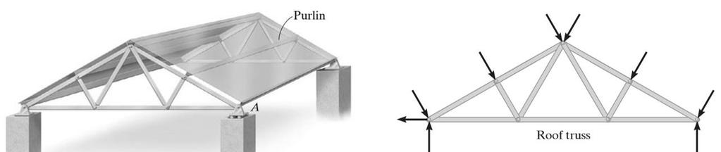
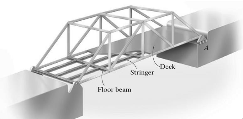
2 Truss Structure composed of slender members joined together at their end points. The members commonly used in construction consist of wooden struts or metal bars.
3 Examples
4 Simple Truss Consists of triangular elements connected together by pinned joints. Forces within its members can be determined by assuming the members are all two-force members connected concurrently at each joint. The member are either in tension or compression, or carry no force.
5
6 Method of Joints The method of joints states that if a truss is in equilibrium, then each of its joints is also in equilibrium. For a plane truss, the concurrent force system at each joint must satisfy force equilibrium. To obtain a numerical solution for the forces in the members, select a joint that has a free-body diagram with at most two unknown forces and one known force.
7 Procedure for Analysis Draw the free-body diagram of a joint having at least one known force and at most two unknown forces. Orient the x and y axes such that the forces on the freebody diagram can be easily resolved into their x and y components and then apply the two force equilibrium equations ΣF x = 0 and Σ F y = 0. Solve for the two unknown member forces and verify their correct sense.
8 Procedure for Analysis Using the calculated results, continue to analyze each of the other joints. Remember that a member in compression pushes on the joint and a member intension pulls on the joint. Also, be sure to choose a joint having at most two unknowns and at least one known force.
9 Example 1 Determine the force in each member of the truss and indicate whether the members are in tension or compression.

10 Example 2 Determine the forces acting in all the members of the truss
11 Example 3 Determine the force in each member of the truss. Indicate whether the members are in tension or compression.
12 Activity Determine the force in each member of the truss. State if the members are in tension or compression.
13 Zero-Force Members Truss analysis using the method of joints is greatly simplified if we can first identify those members which support no loading. These zero-force members are used to increase the stability of the truss during construction and to provide added support if the loading is changed. The zero-force members of a truss can generally be found by inspection of each of the joints.
14 Zero-Force Members If only two non-collinear members form a truss joint and no external load or support reaction is applied to the joint, the two members must be zero-force members. If three members form a truss joint for which two of the members are collinear, the third member is a zero-force member provided no external force or support reaction is applied to the joint.
15 Example 1 Identify the zero-force members
16 Example 2 Identify the zero-force members
17 Example 3 Using the method of joints, determine all the zero-force members of the Fink roof truss. Assume all joints are pin connected.
18 Activity Identify the zero-force members in the truss.
19 Method of Sections States that if a truss is in equilibrium, then each segment of the truss is also in equilibrium. Pass a section through the truss and the member whose force is to be determined. Draw the FBD of the sectioned part having the least number of forces on it.
20 Procedure for Analysis Free-Body Diagram Make a decision on how to cut or section the truss through the members where forces are to be determined. Determine the truss s support reactions Draw the free-body diagram of that segment of the sectioned truss which has the least number of forces acting on it. Establishing the sense of the unknown member forces.
21 Procedure for Analysis Equations of Equilibrium. Moments should be summed about a point that lies at the intersection of the lines of action of two unknown forces, so that the third unknown force can be determined directly from the moment equation. If two of the unknown forces are parallel, forces may be summed perpendicular to the direction of these unknowns to determine directly the third unknown force.

22 Example 1 Determine the force in members GE, GC, and BC of the truss. Indicate whether the members are in tension or compression.

23 Example 2 Determine the force in member CF of the truss. Indicate whether the member is in tension or compression. Assume each member is pin connected.
24 Example 3 Determine the force in member EB of the roof truss. Indicate whether the member is in tension or compression.
ENG202 Statics Lecture 13, Sections
 ENG202 Statics Lecture 13, Sections 6.1-6.3 Simple Truss -A truss is a structure of slender members (Elements) joined together at their end points (Joints). -Elements consist of wooden struts or metal
Chapter 6: Structural Analysis
 Chapter 6: Structural Analysis 1 6.1 Simple Trusses A truss is a structure composed of slender members joined together at their end points. The members commonly used in construction consist of wooden struts
Chapter Objectives. To show how to determine the forces in the members of a truss using: the method of joints and the method of sections.
 Structural Analysis Chapter Objectives To show how to determine the forces in the members of a truss using: the method of joints and the method of sections. Chapter Outline Two-force members Planar (Simple)
Engineering Mechanics Statics. 8. Structural Analysis
 Mechanical Systems Engineering _ 2016 Engineering Mechanics Statics 8. Structural Analysis Dr. Rami Zakaria Simple Trusses Structural Analysis A truss is a structure composed of slender members joined
Statics Chapter 6 Structural Analysis Eng. Iqbal Marie Hibbeler, Engineering Mechanics: Statics,13e, Prentice Hall
 Statics Chapter 6 Structural Analysis Eng. Iqbal Marie iqbal@hu.edu.jo Hibbeler, Engineering Mechanics: Statics,13e, Prentice Hall 6.1 Simple Trusses 6.1 Simple Trusses truss structure composed of straight,
Chapter 6: Structural Analysis
 Chapter 6: Structural Analysis Goals and Objectives Determine the forces in members of a truss using the method of joints Determine zero-force members Determine the forces in members of a truss using the
Truss: Types and Classification. Theory of Structure - I
 Truss: Types and Classification Theory of Structure - I Lecture Outlines Common Types of Trusses Classification of Trusses Method of Joints Zero Force Members Method of Sections 2 TRUSS ANALYSIS A truss
Chapter 3: Analysis of Statically Determinate Trusses PREPARED BY SHAMILAH
 Chapter 3: Analysis of Statically Determinate Trusses PREPARED BY SHAMILAH ANUDAI@ANUAR INTRODUCTION Truss is a structure composed of slender members joined together at their end points The joint connections
Equilibrium. Of a Rigid Body
 Equilibrium Of a Rigid Body 1 Objectives 1. To develop the equations of equilibrium for a rigid body. 2. To introduce the concept of the free-body diagram for a rigid body. 3. To show how to solve rigid
Engineering Mechanics. Trusses
 Engineering Mechanics Trusses Truss 2 Definition of a Truss A truss is an assembly of straight members connected at joints. No member is continuous through a joint. Most structures are made of several
3 Simple and Compound Trusses Simple Truss: a truss whose number of members is given by m = 2j 3, where m = no. of members and j = no. of joints. (For
 2 TRUSSES Learning Objectives 1). To identify zero-force members in a structure. 2). To recognize planar and space (i.e., three-dimensional) truss structures. 3). To understand the assumptions made in
Structural Analysis. Method of Joints. Method of Pins
 Structural Analysis / Method of Pins "This professor would make a good parking lot a6endant. Tries to tell you where to go, but you can never understand him." Trusses Trusses are common means of transferring
ENGINEERING STRUCTURES
 ENGINEERING STRUCTURES In the previous chapter we have employed the equations of equilibrium in order to determine the support / joint reactions acting on a single rigid body or a system of connected members
UNIT -2 (A) BENDING MOMENT AND SHEAR FORCE DIAGRAM FOR BEAMS. MYcsvtu Notes.
 BENDING MOMENT AND SHEAR FORCE DIAGRAM FOR BEAMS. MYcsvtu Notes.") UNIT -2 (A) BENDING MOMENT AND SHEAR FORCE DIAGRAM FOR BEAMS Beam It is a structural member whose longitudinal dimension is large compared to the transverse dimension. The beam is supported along its length
UNIT -2 (A) BENDING MOMENT AND SHEAR FORCE DIAGRAM FOR BEAMS Beam It is a structural member whose longitudinal dimension is large compared to the transverse dimension. The beam is supported along its length
Chapter - 1. Analysis of Truss
 Chapter - 1 Analysis of Truss Dr. Rajesh Sathiyamoorthy Department of Civil Engineering, IIT Kanpur hsrajesh@iitk.ac.in; http://home.iitk.ac.in/~hsrajesh/ Simple Trusses A truss is a structure composed
CIVL 3121 Trusses - Introduction 1/8
 CIVL 3121 Trusses - Introduction 1/8 We will discuss the determinacy, stability, and analysis of three forms of statically determinate trusses: simple, compound, and complex. CIVL 3121 Trusses - Introduction
Chapter 6 ANALYSIS OF STRUCTURES
 hapter 6 NLYSIS OF STRUTURES truss is a structure consisting of straight members connected at their extremities only. The members being slender and unable to support lateral loads, all the loads must be
DEPARTMENT OF ARCHITECTURE ABUBAKAR TAFAWA BALEWA UNIVERSITY, BAUCHI ARC 615: ADVANCED BUILDING STRUCTURES LESSON 4: VECTOR ACTIVE STRUCTURAL SYSTEMS
 DEPARTMENT OF ARCHITECTURE ABUBAKAR TAFAWA BALEWA UNIVERSITY, BAUCHI ARC 615: ADVANCED BUILDING STRUCTURES LESSON 4: VECTOR ACTIVE STRUCTURAL SYSTEMS 4.1 Introduction 4.2 Structural concept of planar trusses
INDETERMINACY AND STABILITY. Old Little Belt Bridge Little Belt Strait Denmark
 INETERMINAY AN STABILITY Old Little Belt Bridge Little Belt Strait enmark Static Indeterminancy To solve a truss using only the equations of equilibrium, the truss must be statically determinate. For a
Spaghetti Bridge Design Project
 Spaghetti Bridge Design Project EI 2018 Contents 1 Project Overview..................................... 1 2 Introduction........................................ 1 3 Theory and Online Simulator.............................
ENR202 Mechanics of Materials Lecture 1A Slides and Notes
 Slide 1 Copyright Notice Do not remove this notice. COMMMONWEALTH OF AUSTRALIA Copyright Regulations 1969 WARNING This material has been produced and communicated to you by or on behalf of the University
Method of Joints. Method of Joints. Method of Joints. Method of Joints. Method of Joints. Method of Joints. CIVL 3121 Trusses - Method of Joints 1/5
 IVL 3121 Trusses - 1/5 If a truss is in equilibrium, then each of its joints must be in equilibrium. The method of joints consists of satisfing the equilibrium equations for forces acting on each joint.
15.2 Approximate Analysis of a Continuous Beam for Gravity Load
 15.2 Approximate Analysis of a Continuous Beam for Gravity Load Figure 15.1 Location of points of inflection and shear and moment curves for beams with various idealized end conditions 1 15.2 Approximate
Approximate Analysis of Statically Indeterminate Structures
 Approximate Analysis of Statically Indeterminate Structures Every successful structure must be capable of reaching stable equilibrium under its applied loads, regardless of structural behavior. Exact analysis
Trusses. 4.1 Introduction
 P T R Trusses 4 4.1 Introduction truss is a structural element composed of a stable arrangement of slender interconnected bars (see ig. 4.1a). The pattern of bars, which often subdivides the truss into
Roof Trusses LAB. Lab for Truss Design and Testing
 Roof Trusses LAB Subject Area(s) Associated Unit Lesson Title Physics Wind Effects on Model Building Lab for Truss Design and Testing Grade Level (11-12) Part # 1 of 3 Lesson # 2 of 2 Time Required 60-90
MECHANICS OF MATERIALS
 Third E CHTER 1 Introduction MECHNICS OF MTERILS Ferdinand. Beer E. Russell Johnston, Jr. John T. DeWolf Lecture Notes: J. Walt Oler Texas Tech University Concept of Stress Contents Concept of Stress Review
three equilibrium and planar trusses Equilibrium Equilibrium on a Point Equilibrium on a Point balanced steady resultant of forces on a particle is 0
 ELEMENTS OF RHITETURL STRUTURES: FORM, EHVIOR, N ESIGN R. NNE NIHOLS SPRING 2014 lecture three Equilibrium balanced steady resultant of forces on a particle is 0 X equilibrium and planar trusses X = Equilibrium
ETABS 2016 Tutorial: Trusses
 ETABS 2016 Tutorial: Trusses Below is a tutorial that was organized for educational purposes at Christian Brothers University only. The procedure of analysis in ETABS 2016 is similar to that of ETABS v9.
Shear Wall Sample Problem
 Shear Wall Sample Problem A long by high concrete block masonry shear wall, reinforced with 4 No. 20 bars (, as shown in the figure below, is subjected to a factored axial load of (including the self-weight)
Figure 1 Shear wall segments with mono-sloped top plates
 All text, images and diagrams Copyright 2004 by Thor Matteson and ICC APPENDIX B ENGINEERING PRINCIPLES OF SHEAR WALLS WITH SLOPING TOP PLATES APA The Engineered Wood Association and others have tested
TRUSSES. Church Truss Vermont Timber Works
 TRUSSES Church Truss Vermont Timber Works Truss Action Consider a loaded beam of rectangular cross section as shown on the next page. When such a beam is loaded, it is subjected to three internal actions:
Types of Structures and Loads
 Types of Structures and Loads THEORY OF STRUCTURES Asst. Prof. Dr. Cenk Üstündağ Asst. Prof. Dr. Cenk Ustundag E-mail: ustunda1@itu.edu.tr Room Nr: 103 Web: http://web.itu.edu.tr/ustunda1 Course Content
Trusses. Giacomo Boffi.
 Analysis of Design of http://intranet.dica.polimi.it/people/boffi-giacomo Dipartimento di Ingegneria Civile Ambientale e Territoriale Politecnico di Milano October 18, 2017 Analysis of Design of Historical
4 parallel-chord truss. 3. Demonstrate your procedure on an example ft. 5 k 5 k 5 k 5 k. 6 ft
 CE 331, Spring 2005 Beam nalogy for Truss Design: 1 / 6 We need to mae several decisions when designing a truss. First, we need to choose a truss shape. Then we need to determine the height of the truss.
Types Of Roofs - Vault
 1 Types Of Roofs - Vault Implementation Of the Concrete On Vault Implementation Of Vault Earthquake Damage 2 Types Of Roofs - Joist And Block 3 Types Of Coverage Roofs-Composite 4 5 Building Structure
SHEAR BEHAVIOR OF RC DEEP BEAMS WITH SOLID CIRCULAR CROSS SECTION UNDER SIMPLY SUPPORTED CONDITION AND ANTI-SYMMETRIC MOMENT
 SHEAR BEHAVIOR OF RC DEEP BEAMS WITH SOLID CIRCULAR CROSS SECTION UNDER SIMPLY SUPPORTED CONDITION AND ANTI-SYMMETRIC MOMENT Koji MATSUMOTO (Tokyo Institute of Technology) Moe YONEHANA (Kajima Corporation)
Analysis of Statically Determinate Structures. W.M.Onsongo. 11~1~~ii~1 ~il~~i~i~',r,~jrll. Nairobi University Press
 Analysis of Statically Determinate Structures W.M.Onsongo 11~1~~ii~1 ~il~~i~i~',r,~jrll 04965208 Nairobi University Press CONTENTS Preface xiii CHAPTER INTRODUCTION I 1.1 Structures 1.2 Loads 1.3 Analysis
Unit II Shear and Bending in Beams
 Beams and Bending Unit II Shear and Bending in Beams 2 Marks questions and answers 1. Mention the different types of supports. i. Roller support ii. Hinged support iii. Fixed support 2. Differentiate between
CE 329 Structural Analysis. Fall 2008
 CE 329 Structural Analysis Fall 2008 Objectives General List Course Objectives Describe Topical Coverage for Class Provide the Formula for Computing your Course Grade Meet somebody new! Objectives Analysis
GUSSET PLATES IN RAILROAD TRUSS BRIDGES FINITE ELEMENT ANALYSIS AND COMPARISON WITH WHITMORE TESTING
 GUSSET PLATES IN RAILROAD TRUSS BRIDGES FINITE ELEMENT ANALYSIS AND COMPARISON WITH WHITMORE TESTING Walid S. Najjar, Ph.D., P.E. 1, Frank DeOrtentiis, P.E. WSP SELLS 555 Pleasantville Road, Briarcliff
Nonlinear Buckling of Prestressed Steel Arches
 Nonlinear Buckling of Prestressed Steel Arches R. Giles-Carlsson and M. A. Wadee Department of Civil and Environmental Engineering, Imperial College London, Exhibition Road, London SW7 2AZ, UK June 22
Example of a modelling review Roof truss
 Example of a modelling review Roof truss Iain A MacLeod The Structure Figure gives an elevation and connection details for a roof truss. It is supported at each end on masonry walls. The trusses are at
EARTHQUAKE-RESISTANT BRIDGE COMPETITION STUDENT GUIDELINES
 EARTHQUAKE-RESISTANT BRIDGE COMPETITION STUDENT GUIDELINES A PROJECT DEVELOPED FOR THE UNIVERSITY CONSORTIUM ON INSTRUCTIONAL SHAKE TABLES Developed by: Kurt McMullin Assistant Professor Department of
Plane Truss Stiffness Matrix
 ecture : Trusses & Grids tiffness Method Plane Truss tiffness Matri The distinguishing feature of a plane truss is that loads are applied in the plane of the structure whereas in a space truss they are
Elastic versus Plastic Analysis of Structures
 Elastic versus Plastic Analysis of Structures 1.1 Stress-Strain Relationships 1.2 Plastic Design Versus Elastic Design Chapter 1 Basic Concepts of Plastic Analysis 1.3 Elastic-Plastic Bending of Beams
SHIP & OFFSHORE STRUCTURES
 SHIP & OFFSHORE STRUCTURES 1 Module Description and Goals The Engineering module offers students an opportunity to: Examine the fundamental principles of engineering behind structure design of ships and
Rounding a method for estimating a number by increasing or retaining a specific place value digit according to specific rules and changing all
 Unit 1 This unit bundles student expectations that address whole number estimation and computational fluency and proficiency. According to the Texas Education Agency, mathematical process standards including
Introduction to Structural Analysis TYPES OF STRUCTURES LOADS AND
 AND Introduction to Structural Analysis TYPES OF STRUCTURES LOADS INTRODUCTION What is the role of structural analysis in structural engineering projects? Structural engineering is the science and art
EFFECTS OF INTERACTION BETWEEN JOINT SHEAR AND BOND STRENGTH ON THE ELAST-PLASTIC BEHAVIOR OF R/C BEAM-COLUMN JOINTS
 EFFECTS OF INTERACTION BETWEEN JOINT SHEAR AND BOND STRENGTH ON THE ELAST-PLASTIC BEHAVIOR OF R/C BEAM-COLUMN JOINTS Hitoshi SHIOHARA 1 ABSTRACT The effects of the interaction between (a) joint shear force
PORTAL FRAMES 1.0 INTRODUCTION
 36 PORTAL FRAMES 1.0 INTRODUCTION The basic structural form of portal frames was developed during the Second World War, driven by the need to achieve the low - cost building envelope. Now they are the
Graphic truss analysis. Graphic truss analysis Copyright Prof Schierle
 Graphic truss analysis Graphic truss analysis Copyright Prof Schierle 2011 1 Truss examples Oakland Bay Bridge Truss joists Graphic truss analysis Copyright Prof Schierle 2011 2 Stadium roof Milan Airport
The Static Analysis of the Truss
 American Journal of Mechanical Engineering, 2016, Vol. 4, No. 7, 440-444 Available online at http://pubs.sciepub.com/ajme/4/7/38 Science and Education Publishing DOI:10.12691/ajme-4-7-38 The Static Analysis
Chapter. Masonry Design
 Chapter Masonry Design The masonry design section contains modules for the analysis of reinforced masonry beams subjected to pure bending and unreinforced masonry walls subjected to axial compression and
CHAPTER 2. Design Formulae for Bending
 CHAPTER 2 Design Formulae for Bending Learning Objectives Appreciate the stress-strain properties of concrete and steel for R.C. design Appreciate the derivation of the design formulae for bending Apply
`Limit State of Collapse in Compression Design of an Axially Loaded Short Column
 `Limit State of Collapse in Compression Design of an Axially Loaded Short Column Cl.39, p-70, IS:456-2000 Members in compression are called columns and struts. The term column is reserved for members which
How to Design a Singly Reinforced Concrete Beam
 Time Required: 45 minutes Materials: -Engineering Paper -Calculator -Pencil -Straight Edge Design For Flexural Limit State How to Design a Singly Reinforced Concrete Beam Goal: ΦMn > Mu Strength Reduction
Members Subjected to Flexural Loads
 Members Subjected to Flexural Loads Introduction: In many engineering structures members are required to resist forces that are applied laterally or transversely to their axes. These type of members are
5.4 Analysis for Torsion
 5.4 Analysis for Torsion This section covers the following topics. Stresses in an Uncracked Beam Crack Pattern Under Pure Torsion Components of Resistance for Pure Torsion Modes of Failure Effect of Prestressing
Learning Virtual Work Method in Statics in a Nutshell: Demystifying It as a Magic Black Box
 Learning Virtual Work Method in Statics in a Nutshell: Demstifing It as a Magic Black Box Ing-Chang Jong Universit of rkansas bstract Statics is a fundamental course in mechanics and is taken b students
Network Arch Bridges. Presenter: Robert Salca technical support engineer, Midas UK
 Network Arch Bridges Presenter: Robert Salca technical support engineer, Midas UK In order to make sure that the sound system is working well a poll will appear shortly on your screens. Please vote by
APPENDIX B ABC STRUCTURES DESIGN GUIDE
 APPENDIX B ABC STRUCTURES DESIGN GUIDE The Cohos Evamy Partners TABLE OF CONTENTS Page No. DISCLAIMER... I 1. STRUCTURAL DESIGN GUIDELINES... 1 2. GENERAL REQUIREMENTS (FIGURE B.2, STEP 1)... 1 3. GENERAL
The Design and Engineering of Fabric Membrane Clad Buildings
 The Design and Engineering of Fabric Membrane Clad Buildings Wayne Rendely PE 132 Columbia Street, Huntington Station, New York, 11746-1220 TEL (631) 351-1843 WayneRendelyPE.com ABSTRACT This paper reviews
Handout 1. Supplementary Info to the DESIGN HANDOUT. Part IA Structural Design Course 2009/10. Supervisor version
 Part IA Structural Design Course 2009/10 Handout 1 Supplementary Info to the DESIGN HANDOUT Supervisor version Text and pictures in grey are omitted from the student version. Fehmi Cirak, February 24,
To have a clear idea about what really happened and to prevent the
 Failure Analysis on Skunk-Arm of Electrical Tower Failure Analysis on Skunk-Arm of Electrical Tower ABSTRACT Ahmad Rivai 1, Md Radzai Said 2 1, 2 Faculty of Mechanical Engineering, Universiti Teknikal
CE 533 Structural Analysis I. Assist. Prof.Dr. Erdal Coskun Teaching Assistant Gökhan Yazici Istanbul Kültür University Civil Engineering Department
 CE 533 Structural Analysis I Assist. Prof.Dr. Erdal Coskun Teaching Assistant Gökhan Yazici Istanbul Kültür University Civil Engineering Department Objectives General Structural Analysis course introduces
PRESTRESSED CONCRETE STRUCTURES. Amlan K. Sengupta, PhD PE Department of Civil Engineering Indian Institute of Technology Madras
 PRESTRESSED CONCRETE STRUCTURES Amlan K. Sengupta, PhD PE Department of Civil Engineering Indian Institute of Technology Madras Module 3: Analysis of Members Lecture 13: Cracking Moment, Kern Point and
Portal frame PLASTIC DESIGN OF PORTAL FRAMES
 Portal frame Monday, November 9, 2015 9:23 AM PLASTIC DESIGN OF PORTAL FRAMES Introduction This section covers a number of features of plastic design of portal frames to BS 5950-1. The frame is analysed
6 TRUSSES. Realistic shapes. Why trusses? Making the joints. Why not trusses? Making the joints. Real applications.
 Page 38 6 TRUSSES Why trusses? truss provides depth with less material than a beam It can use small pieces Light open appearance (if seen) Many shapes possible Schodek p115-120, 145-149; Lateral stability
Teacher Development Program Bringing schools and Engineering together. Year 12 Civil Structures Module
 Teacher Development Program Bringing schools and Engineering together Year 12 Civil Structures Module Teacher Development Program Bringing schools and engineering together INTRODUCTION Civil structures
Bridging Your Innovations to Realities
 Contents: I. Introduction II. Modeling of the cable-stayed bridge a. Bridge wizard b. Stiffening girder III. Initial Cable Forces a. The Unknown Load Factor function - Constraints - Influence matrix IV.
Application of Series Formula Method in Optimization Arrangement of Webs
 World Journal of Engineering and Technology, 2018, 6, 651-660 http://www.scirp.org/journal/wjet ISSN Online: 2331-4249 ISSN Print: 2331-4222 Application of Series Formula Method in Optimization Arrangement
7.1 Transmission of Prestress (Part I)
") 7.1 Transmission of Prestress (Part I) This section covers the following topics. Pre-tensioned Members 7.1.1 Pre-tensioned Members The stretched tendons transfer the prestress to the concrete leading to
7.1 Transmission of Prestress (Part I) This section covers the following topics. Pre-tensioned Members 7.1.1 Pre-tensioned Members The stretched tendons transfer the prestress to the concrete leading to
Displacement Based Assessment and Improvement of a Typical New Zealand Building by an Average Engineer
 Displacement Based Assessment and Improvement of a Typical New Zealand Building by an Average Engineer M.L. Grant LGE Consulting, Masterton 2016 NZSEE Conference ABSTRACT: The Radiohouse building is a
An Application of Strut-and-Tie Models to Deep Beams
 An Application of Strut-and-Tie Models to Deep Beams A thesis submitted to the Graduate School of the University of Cincinnati in partial fulfillment of the requirements for the degree of Master of Science
This final draft of the fib MC2010 has not been published; it is intended only for the purpose of voting by the General Assembly.
 7 Design 382 In the case of combined action of torsion, bending and shear force in a solid section, the core within the idealised hollow cross-section may be used for the transmission of the shear forces.
Question Paper Code : 11410
 Reg. No. : Question Paper Code : 11410 B.E./B.Tech. DEGREE EXAMINATION, APRIL/MAY 2011 Fourth Semester Mechanical Engineering ME 2254 STRENGTH OF MATERIALS (Common to Automobile Engineering and Production
Structural safety and rehabilitation of connections in wide-span timber structures - two exemplary truss systems
 Structural safety and rehabilitation of connections in wide-span timber structures - two exemplary truss systems Philipp Dietsch Dipl.-Ing., Research Associate Michael Merk Dipl.-Ing., Research Associate
Chapter Four Column. Reinforced Concrete Structures 2 (CEng-3122) School of Civil and Environmental Engineering Concrete Material and Structures Chair
 School of Civil and Environmental Engineering Concrete Material and Structures Chair") Reinforced Concrete Structures 2 (CEng-3122) Chapter Four Column 1 School of Civil and Environmental Engineering Concrete Material and Structures Chair 2 1. Introduction 2. Tied and Spiral Columns 3. Sway
Reinforced Concrete Structures 2 (CEng-3122) Chapter Four Column 1 School of Civil and Environmental Engineering Concrete Material and Structures Chair 2 1. Introduction 2. Tied and Spiral Columns 3. Sway
mortarless Design Manual Part 3 (AS 3600:2009) Section 2 Page: DESIGN OF WALLS FOR AXIAL COMPRESSION USING SIMPLIFIED DESIGN METHOD
 Section 2 Page: DESIGN OF WALLS FOR AXIAL COMPRESSION USING SIMPLIFIED DESIGN METHOD") 1 SECTION 2. DESIGN OF WALLS FOR AXIAL COMPRESSION USING SIMPLIFIED DESIGN METHOD Many walls are designed using the simplified design method of AS 3600 Clause 11.5 and this Section 2 of the design manual
1 SECTION 2. DESIGN OF WALLS FOR AXIAL COMPRESSION USING SIMPLIFIED DESIGN METHOD Many walls are designed using the simplified design method of AS 3600 Clause 11.5 and this Section 2 of the design manual
(a) Pin-Pin P cr = (b) Fixed-Fixed P cr = (d) Fixed-Pin P cr =
 Pin-Pin P cr = (b) Fixed-Fixed P cr = (d) Fixed-Pin P cr =") 1. The most critical consideration in the design of rolled steel columns carrying axial loads is the (a) Percent elongation at yield and the net cross-sectional area (b) Critical bending strength and axial
1. The most critical consideration in the design of rolled steel columns carrying axial loads is the (a) Percent elongation at yield and the net cross-sectional area (b) Critical bending strength and axial
Compression Members. Columns I. Summary: Objectives: References: Contents:
 Compression Members Columns I Summary: Structural members subjected to axial compression are known as columns or struts. Stocky columns may not be affected by overall buckling. Stocky columns may fail
A Guide for the Interpretation of Structural Design Options for Residential Concrete Structures
 CFA Technical Note: 008-2010 A Guide for the Interpretation of Structural Design Options for Residential Concrete Structures CFA Technical This CFA Technical Note is intended to serve as a guide to assist
Buckling Analysis. Buckling Analysis
 Objective of Buckling Analysis: To Find Buckling load factor To Find Buckling mode shape To determine member effective lengths Hands-on Exercise Using SPACE GASS What is : An accurate buckling analysis
ARCH 331. Study Guide for Final Examination
 ARCH 331. Study Guide for Final Examination This guide is not providing answers for the conceptual questions. It is a list of topical concepts and their application you should be familiar with. It is an
Professor Terje Haukaas University of British Columbia, Vancouver Approximate Methods
 Approximate Methods Modern structural analysis offers a host of methods and computer tools to determine deformations and internal forces in structures. For instance, the finite element method facilitates
Optimization Design of Arm Frame of Folding Arm Type Tower Crane Based on ANSYS Ge-ning XU, Wen-ju LIU * and Yan-fei TAO
 2016 International Conference on Applied Mechanics, Mechanical and Materials Engineering (AMMME 2016) ISB: 978-1-60595-409-7 Optimization Design of Arm Frame of Folding Arm Type Tower Crane Based on ASYS
8 ft. 5 k 5 k 5 k 5 k. F y = 36 ksi F t = 21 ksi F c = 10 ksi. 6 ft. 10 k 10 k. CE 331, Spring 2003 HW 2a 1 / 6 Beam Analogy -Theory
 E 331, Spring 2003 HW 2a 1 / 6 We need to make several decisions in designing trusses including truss shape, height and member sizes. lthough we will likely use a computer program to select the final member
Engineering Materials
 Engineering Materials PREPARED BY IAT Curriculum Unit August 2010 Institute of Applied Technology, 2010 Module Objectives After the completion of this module, the student will be able to: Explain the difference
PRESTRESSED CONCRETE STRUCTURES. Amlan K. Sengupta, PhD PE Department of Civil Engineering Indian Institute of Technology Madras
 PRESTRESSED CONCRETE STRUCTURES Amlan K. Sengupta, PhD PE Department of Civil Engineering Indian Institute of Technology Madras Module 7: Transmission of Prestress Lecture 30: Pre-tensioned Members Welcome
Estimate the endurance strength in MPa if the rod is used in rotating bending.
 348 Mechanical Engineering Design PROBLEMS Problems marked with an asterisk (*) are linked to problems in other chapters, as summarized in Table 1 1 of Sec. 1 16, p. 24. Problems 6 1 to 6 63 are to be
Load capacity of slender reinforced concrete walls governed by flexural cracking strength of concrete
 Magazine of Concrete Research, 2000, 52, No. 3, June, 169±175 Load capacity of slender reinforced concrete walls governed by flexural cracking strength of concrete J. G. Sanjayan Monash University This
Science Park High School Math Summer Assignment
 Name: Science Park High School Math Summer Assignment Review of Math Skills for Students Entering Geometry and/or Algebra II DUE THE FIRST DAY OF SCHOOL The problems in this packet are designed to help
Chapter 3: Torsion. Chapter 4: Shear and Moment Diagram. Chapter 5: Stresses In beams
 Chapter 3: Torsion Chapter 4: Shear and Moment Diagram Chapter 5: Stresses In beams Torsion Torsion or Torque, T, put simply, is referred to as a twisting moment. θ The derived formulas are: Where: Torsional
MECHANICS OF MATERIALS
 Lecture Notes: Dr. Hussam A. Mohammed Al- Mussiab Technical College Ferdinand P. Beer, E. Russell Johnston, Jr., and John T. DeWolf Introduction Concept of Stress The main objective of the study of mechanics
Chapter Five Torsion. Reinforced Concrete Structures 2 (CEng-3122)
") Reinforced Concrete Structures 2 (CEng-3122) Chapter Five Torsion 1 School of Civil and Environmental Engineering Concrete Material and Structures Chair 2 1. Introduction 2. Torsional Resistance 3. Analysis
Reinforced Concrete Structures 2 (CEng-3122) Chapter Five Torsion 1 School of Civil and Environmental Engineering Concrete Material and Structures Chair 2 1. Introduction 2. Torsional Resistance 3. Analysis
A SEMI-RIGOROUS APPROACH FOR INTERACTION BETWEEN LOCAL AND GLOBAL BUCKLING IN STEEL STRUCTURES
 A SEMI-RIGOROUS APPROACH FOR INTERACTION BETWEEN LOCAL AND GLOBAL BUCKLING IN STEEL STRUCTURES KULDEEP VIRDI METNET Seventh International Seminar, Izmir, 11-12 October 2012 1 OUTLINE Stiffened Plate Panels
eleven rigid frames: compression & buckling ELEMENTS OF ARCHITECTURAL STRUCTURES: FORM, BEHAVIOR, AND DESIGN DR. ANNE NICHOLS SPRING 2014 lecture
 ELEMENTS OF ARCHITECTURAL STRUCTURES: FORM, BEHAVIOR, AND DESIGN DR. ANNE NICHOLS SPRING 2014 lecture eleven rigid frames: compression & buckling Rigid Frames 1 http:// nisee.berkeley.edu/godden Rigid
Structural Analysis III Qualitative Analysis
 Structural nalysis III Qualitative nalysis 2010/11 r. olin aprani 1 ontents 1. Introduction... 3 1.1 ackground... 3 1.2 Reading Material... 4 1.3 Software... 5 2. Qualitative nalysis Techniques... 6 2.1
Performance of a Structure
 Performance of a Structure Materials - Performance Of A Structure - BLM 7.4.1 - Bridge Structure - BLM 7.4.2 - Spreadsheet Example - BLM 7.4.3 - Testing the Strength of 2-D Shapes BLM 7.4.4 - Struts and