PROJECT MANUAL PART 2
|
|
|
- Christal Farmer
- 5 years ago
- Views:
Transcription
1 PROJECT MANUAL PART 2 TECHNICAL PLANS & SPECIFICATIONS FOR THE CONSTRUCTION OF: AGRICULTURE WELL RELOCATION PROJECT RANCHO CAMPANA HIGH SCHOOL FOR: OXNARD UNION HIGH SCHOOL DISTRICT Oxnard, California Project No. 529 November 2013
2 Oxnard Union High School District November 2013 (Project No. 529) TECHNICAL PLANS AND SPECIFICATIONS For OXNARD UNION HIGH SCHOOL DISTRICT WELL RELOCATION PROJECT Well Construction Project Contents of Technical Specifications: 1. Technical Specifications 2. Plate 1 - Project Location & Site Access Map 3. Plate 2 Construction Site Map 4. Plate 3 Preliminary Well Design Drawing 5. Plate 4 Dissimilar Metal Adapter 6. Plate 5 Dual Swab Assembly Drawing Side View 7. Plate 6 Dual Swab Assembly Drawing Top View 8. Plate 7 Preliminary Wellhead Construction Drawing 9. Attachment A 02N/20W-19A01S Well Logs 10. Attachment B NPDES Permit 11. Attachment C Preliminary Well Destruction Requirements 12. Attachment D Well Site Improvement Drawings (3) and Contractor Bid Sheet 1
3 Oxnard Union High School District November 2013 (Project No. 529) TECHNICAL SPECIFICATIONS WATER SUPPLY WELL CONSTRUCTION PROJECT USING DIRECT OR REVERSE CIRCULATION FLUID ROTARY DRILLING PROCESS SECTION 1 - PROJECT SCOPE OF WORK The intent of these Contract Documents and Specifications is to construct, develop, and test a water supply well that will be drilled by using either the conventional direct circulation or reverse circulation rotary drilling method as specified herein. The design production capacity of the well is 1,400 gallons per minute (gpm) with a specific capacity on the order of 45 gallons per minute per foot of drawdown (gpm/ft) or greater. As part of the project, the existing irrigation well will be destroyed. All work shall conform to these Specifications, American Water Works Association Standard A100, Department of Water Resources Bulletin 74-81, Water Well Standards: State of California and supplement Bulletin California Well Standards, and Standard Specifications For Public Works Construction, 2012 Edition ( Greenbook ). SECTION 2 - PROJECT LOCATION The project location is shown on Plate 1 Project Location and Site Access Map. The project is located in Camarillo, California. The area immediately around the new well location is primarily agricultural. The closest residential area is located approximately 1,200 feet to the west and is shown on Plate 2 Construction Site Map. SECTION 3 - PROJECT SCHEDULE The Contractor shall conduct drilling operations around-the-clock (24 hours per day) from commencement of pilot hole drilling through placement of the final sanitary seal. At the preconstruction meeting, which will be conducted before mobilization or any onsite work, the construction manager (Engineering Geologist) for the Oxnard Union High School District (District) shall review the Contractor s submitted description of the drilling method, fluid processing system and equipment, and drilling fluid additives that are proposed for use. The drilling, construction, and testing of the well shall be completed within ninety (90) calendar days from the date the work is to begin. The 90- day period shall begin 30 working days from the date the District gives the Contractor the written Notice to Proceed[GHP1]. Please Note: At no time can there be a period of time exceeding two weeks (14 days) where irrigation is not available. 2
4 Oxnard Union High School District November 2013 (Project No. 529) SECTION 4 - LOCAL HYDROGEOLOGY The well project is located in the Pleasant Valley Groundwater Basin. The underlying geology is comprised predominately of loose to moderately-cemented coarse-grained sand, gravel, and cobble layers interbedded with layers of silt and stiff or sticky clay. The Contractor is advised of these potential widely variable and possibly problematic subsurface conditions and shall propose the use of drilling equipment and methods that will achieve rapid penetration rates and at all times maintain borehole stability. Borehole stability is the responsibility of the Contractor. Borehole stability shall be accomplished using materials and methods that will not cause formation damage that could potentially decrease the production of the well. Groundwater conditions in the area have been affected by years of production and return flows from overlying land uses. Little data are available about the piezometric surface of groundwater contained in the shallow zones in the vicinity of the project site. While the static water level in the target production zone is anticipated to be on the order of 150 feet below ground surface (bgs), shallower perched, semi-perched, or confined aquifer zones may contain groundwater with a piezometric surface above the regional groundwater level (i.e., 5 feet bgs). Pressure differentials of this type can be problematic during fluid rotary drilling if drilling fluid conditions are not properly maintained and if the fluid level in the borehole is not maintained at or above ground surface. The Contractor is advised of these potential widely variable and possibly problematic subsurface conditions and shall propose the use of drilling equipment and methods that will achieve rapid penetration rates and maintain borehole stability at all times. An electric log of State Well No. 02N/20W-19A01S pilot hole (the existing irrigation well that is being replaced) is included as Attachment A State Well No. 02N/20W-19A01S Well Logs to provide an indication of the widely variable geologic strata anticipated. The Contractor is informed that several other wells operate in the vicinity of the well site. These wells may be active throughout the duration of the well drilling and construction activities. The new well will be completed in the same aquifer as some of these production wells. Drilling fluid properties (specifically water loss) shall be maintained (and strictly monitored) to decrease any potential damage to the aquifer zones being produced by the existing wells. SECTION 5 - PROJECT OVERVIEW The work for this well construction project includes the furnishing of all materials, labor, equipment, fuel, tools, transportation, and services for drilling, construction, development, testing, and sterilization of a production well as described in these specifications. The general work required for construction of the well includes: 1. Mobilize the drill rig and the requisite fluid processing equipment specified for drilling the well bore; 3
5 Oxnard Union High School District November 2013 (Project No. 529) 2. Drill a pilot borehole to a depth of approximately 850 feet and provide lithologic cuttings of the formation materials at 10 foot intervals; 3. Conduct electric geophysical surveys of the pilot bore using spontaneous potential (sp), and multiple resistivity sondes; 4. Ream to a depth of approximately 490 feet a minimum 28-inch diameter borehole, and maximum 22-inch diameter ream from 490 feet to total depth and at the option of the District, caliper the reamed hole; 5. Install approximately 490 feet of 14-inch-diameter low carbon and stainless steel steel casing, approximately 60 feet of 12-inch-diameter stainless steel casing and approximately 250 feet of stainless steel wire wrap screen; 6. Install approximately 530 feet of permanent gravel feed tube; 7. Install a select gradation of gravel pack in the annular space of the well from the bottom of the well up to a depth of 500 feet. Construct a cement sanitary seal from the top of the gravel pack to ground surface; 8. Conduct a well alignment test; 9. Swab, surge, and airlift pump the well; 10. Develop the well with the pump and surge method; 11. Conduct production testing of the well using a variable rate pump with a capacity ranging from 500 to 2,000 gpm and a constant discharge of 1,500 gpm; 12. Test groundwater for and comply with NPDES permit; 13. Conduct a video survey of the completed well; 14. Destroy existing SWN 02N/20W-19A01S and install existing pump in new well; 15. Cleanup and restore the well site. All work shall be conducted in accordance with these specifications. SECTION 6 - PROJECT TERMINATION The District reserves the right to terminate the work on the well at any time. In such an event, the Contractor shall be paid for work completed at that time on the basis of the unit bid prices. The District reserves the right to select an alternate well site to replace 4
6 Oxnard Union High School District November 2013 (Project No. 529) an abandoned well. If the District chooses an alternate site, the Contractor shall be paid for the work done on the alternate well on the basis of the unit bid prices. Should the District terminate the work on the well and abandon the well due to the fault of the Contractor, the Contractor shall not be paid for work completed on the abandoned well. SECTION 7 OXNARD UNION HIGH SCHOOL AND AGENCY NOTIFICATIONS The Contractor shall notify the District and the appropriate state, local and federal agencies in advance of the commencement and completion of each contract operation, including well seal inspection as required by the well construction permit(s). The Contractor shall record the commencement and completion of each contract operation. SECTION 8 - OTHER REQUIRED WORK Other work to be done by the Contractor shall include; applying for a Ventura County well drilling and destruction permit(s), collecting geologic samples as directed by the Engineering Geologist; keeping a time-drilling log; proper cleaning and restoration of the drilling site upon completion of work; and doing all things necessary for drilling and completion of the work called for under these Specifications. The time-drilling logs will be made available by the Contractor for review by the Engineering Geologist on a daily or work shift basis. The District has designated a location for discharge of water produced during final well development and production testing. The clear water discharge point is located approximately 2,400 feet from the new well site. Prior to discharge, all pre-discharge testing and reporting requirements shall be completed. The Contractor shall provide a minimum 72-hour notification to the District s designated representative or as otherwise necessary to meet the NPDES reporting requirements (see Attachment B). Clarity of the discharge water and all other parameters shall be in compliance with the District s discharge conditions. It will be the Contractor s responsibility to test, maintain and insure that all discharged fluids are adequately conveyed to the designated area of discharge and that the discharged waters comply with discharge permit conditions. The Contractor shall submit an application and obtain an encroachment permit from City of Camarillo to allow discharge of development and testing water to the City s debris basin. The Contractor shall be responsible for obtaining construction water for drilling and construction of the well from the District system at the location designated by the District. It will be the Contractor s responsibility to provide and install all piping, valves, storage tanks and all appurtenances necessary for obtaining the water at the site from the designated source of supply (the existing well) and coordinating with the land management company operator to operate the well during day-time, routine irrigation hours. Alternatively, the Contractor can obtain a construction water meter from the City 5
7 Oxnard Union High School District November 2013 (Project No. 529) of Camarillo and utilize City water for well construction. The cost of the water supply and transportation to the point of use shall be the responsibility of the Contractor. It will be the Contractor s responsibility to confine all drill cuttings and fluids within the designated work area. It will be the Contractor s responsibility to contain and remove drilling fluids and cuttings from the project area during and/or upon completion of work. If the Contractor is unable to contain the volumes of drill cuttings and fluids within the designated temporary containment area, it will be the Contractor s responsibility to transport the materials to a permanent disposal site at the Contractor s expense. Well site preparation will be the responsibility of the Contractor. The Contractor shall be responsible for maintaining the integrity of the work area throughout the entire well construction process. SECTION 9 - NUISANCE WATER The contractor shall implement Best Management Practices and/or Best Available Technologies to anticipate and control nuisance water. It is anticipated that nuisance water, such as rainfall, groundwater, irrigation run-off, or surface runoff may occur within the construction site and on or adjacent project access roads during the period of construction under this contract. The Contractor, by submitting his bid, will be held to have investigated the risks arising from such waters, and to have made his bid in accordance therewith. The Contractor shall at all times protect the work from damage by such waters and shall take all due measures to prevent delays in progress of the work caused by such waters. The Contractor is advised of the condition that shallow groundwater may rise near ground surface during the time of drilling and shall only propose to utilize drilling methods and well construction techniques that will maintain a stable borehole environment under these conditions. Borehole stability is the sole responsibility of the Contractor. SECTION 10 NOISE CONTROL The Contractor shall be responsible to take any mitigation measures necessary to comply with City and County noise ordinance conditions. These measures may include sound attenuation by insulating specific pieces of equipment and/or the use of highly effective sound reducing exhaust mufflers. SECTION 11 - SERVICES PROVIDED BY THE OXNARD UNION HIGH SCHOOL DISTRICT 6
8 Oxnard Union High School District November 2013 (Project No. 529) The District will provide the final well design details to the Contractor within 4 business days of receiving the geophysical log of the pilot borehole. The final design shall include well casing and screen intervals, screen slot opening size, and gravel pack size. [GHP2] SECTION 12 - ACCESS FOR INSPECTION The Contractor shall provide proper facilities for access and permit inspection of any part of the project site by the District, its agents, and other regulatory agency representatives. SECTION 13 SUBMITTALS All records shall be available to the District at all times on the job site, and copies of all records shall be submitted to the District and its Geologist within 14 days of project completion or as otherwise requested during project performance. The records to be submitted by the Contractor shall include: 1. Copies of the Ventura County Well Permit(s). 2. Copies of the completed State of California Well Completion Reports (Driller's Log). 3. All geophysical logs; 5 copies of each on paper, one electronic copy in Adobe Portable Document Format (PDF). 4. Caliper survey log of borehole reams; 5 copies of each on paper, one electronic copy in Adobe Portable Document Format (PDF). 5. Cement delivery tickets for the sanitary seal around the conductor, well casings, and the surface pad. 6. Steel certifications for all blank casing and accessory tubing and screen design submittal for all well screen sections. 7. Sieve analyses and delivery tickets for the gravel pack. 8. The mechanical development (airlifting and swabbing) records, which will include total volumes and water quality field measurements of discharge fluids. 9. Pumping development sheets including Rossum sand measurement records. 10. Step drawdown and constant rate discharge test records showing water levels, pumping rates, drawdown, and specific capacities. 11. Downhole video survey 2 DVD copies. 12. Inspection report of existing pump equipment upon removal from existing well and confirmation testing details of equipment to confirm proper operation. 7
9 Oxnard Union High School District November 2013 (Project No. 529) 13. Delivery tickets for the inert backfill sand/gravel material used for well destruction. 14. Cement delivery tickets for the destruction of the existing agricultural water well. 8
10 Oxnard Union High School District November 2013 (Project No. 529) SECTION 14 - MOBILIZATION/DEMOBILIZATION (BID ITEM NO. 1) Scope Mobilization/Demobilization shall include the purchase of insurance, labor and material bond; performance bond; transportation of personnel, equipment, and operating supplies to and from the sites; establishment of offices, buildings, portable sanitary facilities, temporary construction water and other necessary facilities at the site; other preparatory work at the site and mobilization for work required by the Contractor. The Contractor shall provide one complete direct circulation or reverse circulation mud rotary drilling unit; all tools, accessories, power, fuel, materials, supplies, noise suppression, lighting, water, and other equipment; and experienced personnel necessary to conduct efficient drilling operations in the manner specified. The drilling unit shall be in good condition and have a minimum (lifting) capacity of 200,000 pounds for the mast and subbase. The Contractor shall also provide a vertical line-shaft turbine pump capable of pumping a minimum of 2,000 gpm against 500 feet of total dynamic head (TDH). The Contractor shall also provide all equipment and personnel to maintain and restore the site as required. The Contractor shall provide mud tank(s) to accommodate a volume that is greater than twice the volume of the total reamed borehole. Drilling fluid processing equipment is required for construction and shall at a minimum consist of a shale shaker, desanding and desilting cones, and a mud shear apparatus and agitating equipment for proper mixing and agitation of drilling fluid additives. The use of mud pits or settling tanks for mud conditioning will not be allowed. Measurement and Payment Payment for Bid Item No. 1 will be in two payments, ½ upon mobilization and ½ upon completion and acceptance of the project by the District. The lump sum price bid for this item shall not exceed 20 percent of the total amount of the Contractor s bid. If the cost for Mobilization/Demobilization exceeds 20 percent of the total bid cost, it shall be considered grounds for rejection of the entire bid as nonresponsive. Payment will not be made under this item for the purchase of items or costs of materials having a residual value, the purchase costs of materials to be incorporated in the project, or the purchase costs of operating supplies. Payment for Mobilization/Demobilization will constitute full compensation for all labor, fuel, materials, equipment, and all other items necessary and incidental to completion of the work, removal and replacement of interfering fences, gates and other obstructions. 9
11 Oxnard Union High School District November 2013 (Project No. 529) SECTION 15 - CONDUCTOR CASING (BID ITEM NO. 2) Scope This item shall consist of drilling and installing a 30-inch-diameter (minimum) conductor (surface) casing: to a minimum depth of 40 feet below ground surface to stabilize the site for well construction and allow progress without interruption. Construction Materials The (minimum) 30-inch-diameter conductor (surface) casing shall be ASTM Designation A-53 Grade B or A-139 Grade B steel plate, having a minimum wall thickness of 3/8- inch and being a minimum of 40 feet in length. The conductor sanitary seal shall consist of a neat cement, 10.5-sack sand slurry cement mixture or a 6-sack pea gravel mix as permitted by the County and as approved by the Engineering Geologist. Construction Methods The Contractor shall drill a minimum 34-inch-diameter borehole and furnish and install a minimum 30-inch-diameter conductor casing to a depth of 40 feet below ground surface. The drilling method for the conductor casing is optional; however, the casing shall be sufficiently plumb and straight to allow completion of the well as specified in the following sections of this contract and not interfere with the installation of any of the well materials. The Contractor is advised of potentially shallow perched groundwater conditions that can make use of some types of drilling methods problematic for borehole stabilization. The conductor sanitary seal shall be considered as a portion of the well s entire sanitary seal. Placement shall be conducted in accordance with County permit requirements and be pumped in place using the positive displacement method with a pneumatic grout pump and construction tremie pipe set 2 feet off the bottom of the sealing zone (or as otherwise required by the well construction permit). Measurement and Payment Payment for conductor hole drilling, casing installation, and cement grout seal will be made on a lump sum basis at the unit price bid for Bid Item No. 2. Such payment will be considered full compensation for furnishing all labor, materials, tools, and equipment necessary and incidental to complete the conductor casing installation. 10
12 Oxnard Union High School District November 2013 (Project No. 529) SECTION 16 - PILOT BORE DRILLING (BID ITEM NO. 3) Scope This item shall consist of drilling a pilot bore from the base of the conductor casing to a depth of 850 feet as shown on Plate 3 - Preliminary Well Design Drawing or to the final depth determined by the Engineering Geologist. The Contractor shall use the approved drilling method and fluid parameters specified herein. Construction Materials The Contractor shall provide a description of all bit types, bit sizes, drilling fluid system and drilling fluid additives to be used concurrently with the submittal of its bid package. This submittal must include information regarding the types of fluid to be used, intended drilling fluid weights, viscosities, sand and solids contents, water loss control, and the name of the supplier. Failure to provide this information may render the bid to be considered unresponsive. The name and qualifications of the Mud Engineer that the Contractor intends to use must also be submitted with the bid. In order to comply with the drilling fluid properties specified herein, it is the responsibility of the Contractor to have all equipment and drilling fluid additives onsite at all times during drilling and reaming procedures. The Contractor shall possess the equipment necessary to measure the drilling fluid properties, including: weight, viscosity, sand content, and water loss/filter cake thickness. Drilling shall not commence until the Contractor demonstrates to the Engineering Geologist that the devices used for testing of drilling fluid properties are operable and calibrated. The drilling fluid shall possess such characteristics as are required to adequately maintain the integrity of the borehole wall and prevent caving as drilling progresses and to permit recovery of representative samples of cuttings. The drilling fluid shall possess such characteristics that it can be readily removed from the hole during the placement of the gravel pack and during development of the well. Only fresh water with only high grade commercial chemical products in common usage for water well drilling shall be used in drilling fluid make up. The drilling fluid shall be a commercial quality high grade bentonite clay system with a polymer supplement such as, Quick Gel, Hydrogel, Aquagel, Drispac, or an equal approved by the Engineering Geologist, to control water loss and maintain the mud properties specified. Drilling fluid with a mixture of unprocessed clay (bentonite), Super Ga Quich or other biodegradable material will not be permitted. The Engineering Geologist s approval of all drilling fluids prior to any drilling operations is required. The use of a non-bentonite clay drilling fluid such as Poly-Bore will not be permitted for this project. 11
13 Oxnard Union High School District November 2013 (Project No. 529) All drilling fluids shall be mixed fresh onsite. The reuse or recycling of old drilling fluids will not be allowed. The Contractor shall make every effort to ensure that mud conditions will create a wall cake that can be removed from the production zones during the development of the well and prevent swelling of clay layers during construction. The drilling fluid to be utilized should possess properties necessary to inhibit this possibility. To maximize well performance, it is crucial that proper drilling fluid maintenance restrict water loss (mud invasion) from the borehole into the aquifer zones and minimize formation damage. Proper control of the drilling fluid during both the pilot hole and reaming operations must be maintained to the specified parameters. The fluid system shall be sufficient to maintain the fluid properties listed below at all times. If the specified drilling fluid properties are exceeded, the Engineering Geologist may suspend further drilling operations until adjustments are made to allow for the system and fluids to meet specifications. Hole stability at all times, including periods when drilling is suspended due to failure to meet drilling fluid specifications, is the sole responsibility of the Contractor. If proper control of the drilling fluid is not maintained to the satisfaction of the Engineering Geologist, the Contractor may be required, at the Contractor s expense, to retain or employ an experienced, qualified Mud Engineer on the job during all operations to supervise and maintain drilling fluid properties that comply with the conditions specified. Drilling mud processing equipment is required for this construction project and shall at a minimum consist of a 3,000 gallon mud tank with fluid circulation nozzles/jets to maintain fluid movement and prevent settlement of solids, a shale shaker, desanding and desilting cones, and a mud shear apparatus for proper mixing of drilling fluid additives. Mud pits or settling tanks for mud treatment will not be allowed. The mud system shall be capable of handling a minimum of 500 gpm and designed to remove all but the finest of drill cuttings from the drilling fluid. The fluid processing system shall be installed in the circulation system between the point of discharge from the borehole and the point of recirculation into the well bore. This equipment must keep the sand concentration in the drilling fluid below one percent. All fluid additives shall be hydrated and properly mixed prior to entry into the drill hole. The drilling rig must at all times be provided with the following fully operational and calibrated drilling fluid measuring devices: (a) Drilling fluid weight scale; (b) Drilling fluid viscosity funnel (Marsh Funnel); (c) Drilling fluid sand content cone and screen; (d) Drilling fluid mud press for water loss and filter cake. The Contractor shall measure and record the properties of the fluid entering the borehole every two (2) hours during all drilling activities. The drilling fluid shall have the following properties in accordance with API Code RP-13B (or recent modification) "Recommended Standard Procedure for Testing Drilling Fluids:" 12
14 Oxnard Union High School District November 2013 (Project No. 529) Weight, a maximum to 72 pounds per cubic foot (9.6 pounds per gallon). Viscosity, using a Marsh Funnel a maximum of 50 seconds and a minimum of 31 seconds. Sand Content, of mud entering the borehole, a maximum of 1.0 percent by volume during all aspects of drilling. Water loss, a maximum of 15 cubic centimeters (cc), with a wall cake thickness no greater than 1/16-inch during all aspects of drilling. If drilling fluid properties exceed the specified parameters, the Engineering Geologist may request immediate suspension of drill hole advancement and the drilling fluid shall be reconditioned and brought into compliance with the specified properties. If reconditioning cannot be achieved, the drilling fluid shall be disposed and replaced with a new mixture that complies with the specified fluid parameters prior to commencement of drill hole advancement. A record shall be maintained showing any variation in the addition and amount of approved chemical products or water required during drilling. The depths at which such changes are required shall be shown in the daily reports. The driller shall record the depths of excess mud loss or loss of circulation in the well bore. At no time during the well drilling or construction process shall fluid loss prevention material (i.e., Hole Plug, Magma Fiber, N-Seal, etc.) be introduced into the borehole. The Contractor must keep records that provide the following information: A log of drilling bit types and the depths at which bit changes are made. A depth tally of the drill string. A log of drilling fluid tests and additives used. A log of the cuttings, providing the depths and descriptions of the earth materials encountered. The Contractor shall collect cutting samples at 10- foot intervals during the pilot bore drilling. Samples shall be placed in quart sized zip-lock plastic bags (or larger) and the sample depth interval clearly labeled with a permanent marker. All measurements for depth shall be referenced to existing ground surface at the well site. The Contractor shall be responsible for obtaining construction water for drilling and construction of the well from the District irrigation system at the location designated by the District. It will be the Contractor s responsibility to provide and install a 2-inchdiameter connection on the 10-inch-diameter mainline and a 2-inch-diameter flow control valve. The Contractor shall provide all piping, temporary valves, storage tanks and all appurtenances necessary for transporting the water to the site from the designated source of supply (the existing well) and coordinating with the land management company operator to operate the well during day-time, routine irrigation hours. The Contractor shall submit with its bid the manufactures details on the type of 2-inch-diameter water connection that will be installed. The Contractor shall install two (2) temporary 20,000 gallon tanks on the site (40,000 gallon storage capacity or more) to allow for fill up during the day when the farm management company is operating the 13
15 Oxnard Union High School District November 2013 (Project No. 529) well for irrigation. It shall be the Contractors responsibility to monitor and maintain its water supply for construction. Alternatively, the Contractor can obtain a construction water meter from the City of Camarillo and utilize City water for well construction. The cost of the water supply and transportation to the point of use shall be the responsibility of the Contractor. Construction Methods A pilot bore having a diameter of between approximately 12 and 17 inches, shall be drilled for the well pilot hole to the depth specified by the Engineering Geologist. The pilot hole shall be drilled from the base of the conductor casing to the final specified depth using the direct or reverse circulation mud rotary drilling process. The wall of the drill hole shall be held in place at all times with a circulating fluid which shall be washed out during the gravel pack placement process and subsequent well development. The work shall be performed with equipment, which is adequate to perform all phases of well construction. If, in the opinion of the Engineering Geologist, the Contractor s equipment is not capable of satisfactorily performing the work provided for in these specifications, the Contractor, at his own expense, shall substitute equipment satisfactory to the Engineering Geologist. The Contractor shall take the appropriate measures necessary to protect the pilot bore from caving and not plug the aquifers that will yield groundwater to the completed well. It will be the Contractor s responsibility to provide and maintain a temporary containment area for drill cuttings and provide temporary storage tanks (Baker Tanks) to contain construction water and drilling fluids. It will be the Contractor s responsibility to remove and properly dispose of all cuttings and fluids produced during the project. It will be the Contractor s responsibility to maintain the area designated for cuttings and fluid storage. All cuttings and drilling fluids produced during the project which cannot be contained in the areas must be transported from the drill site and properly disposed of at the Contractor s expense. In order to insure that drilling of the pilot bore meets alignment specifications, the Contractor shall furnish and employ a self-checking mechanical drift indicator to measure hole deflection. The mechanical drift indicator shall be an Eastman Mechanical Drift Indicator available from the Eastman Oil Well Survey Company, or approved equal. A 3 degree unit shall be used with the indicator. Drift indications shall be taken at 100-foot intervals immediately after each 100-foot-increment of pilot bore is drilled. The first drift survey shall be conducted at a depth 100 feet bgs and the last drift survey shall be conducted at a depth of 500 feet bgs. The drift from vertical shall be not more than 0.25 of 1 degree. Excess deviation shall be corrected by the Contractor at his own expense prior to proceeding with hole advancement. At 10-foot intervals, or as directed by the Engineering Geologist, the Contractor shall take a large (one percent) representative sample of drill cuttings from the interval and shall label and preserve each sample in a re-sealable plastic bags (i.e., zip-lock ) 1 14
16 Oxnard Union High School District November 2013 (Project No. 529) quart size or larger supplied by the Contractor. All containers shall be labeled to indicate the depth interval of the collected sample. The samples shall be properly stored by the Contractor in a manner as to prevent breakage or loss until inspected by the Engineering Geologist and final use for well construction design is complete. The driller shall prepare a record of construction activities of each shift for the Engineering Geologist. In addition, a time drilling log of the hole shall be kept by the driller and will consist of recording the time (in minutes) required to drill each 10-foot interval of the hole. Upon completion of the pilot bore, geophysical logging of the hole shall be conducted for the purpose of providing information for the final design of the well. Determination of the final depth of the pilot borehole shall be made after completion of the geophysical logging. Measurement and Payment Payment for pilot bore drilling will be made on a linear foot basis from the bottom of the conductor to the depth specified by the Engineering Geologist at the unit price bid for Bid Item No. 3. Such payment will be considered full compensation for furnishing all labor, materials, tools and equipment necessary and incidental to complete the pilot bore from the bottom of the conductor casing to the final depth of the pilot hole as specified by the Engineering Geologist. SECTION 17 - GEOPHYSICAL LOGGING (BID ITEM NO. 4) Scope This item shall consist of performing professional geophysical logs, consisting of spontaneous potential (sp), 16-inch and 64-inch normal resistivity, and 6-foot lateral resistivity surveys. Construction Methods The Contractor shall furnish services for geophysical logs in the pilot hole. Borehole geophysical logs, consisting of spontaneous potential (sp), 16-inch and 64-inch normal resistivity, and 6-foot lateral resistivity surveys, shall be made by the Contractor as directed by the Engineering Geologist. A guard or single point resistivity survey may be substituted for the 6-foot lateral resistivity survey. If reverse rotary drilling is being used for well drilling, the electric log shall be accompanied by a caliper survey of the borehole to allow interpretation of borehole diameter effects on the electrical signature of the e- log. The caliper shall be considered as part of the geophysical electric log suite for reverse rotary drilling. During drilling of the well, the driller shall maintain proper mud consistency to prevent caving of loose sand and gravel and swelling of clay zones to ensure the hole is open to the bottom for geophysical logging. If the logging probe fails to descend to the desired 15
17 Oxnard Union High School District November 2013 (Project No. 529) depth, the Contractor, at its own expense, shall condition the hole and permit the logging probe to descend to the bottom of the hole. Standby time will not be paid for additional cleaning and conditioning of the hole to enable logging operations to proceed. Standby time for the drill rig to allow geophysical survey completion shall be included in this work task. Upon completion of downhole data collection, five (5) final quality copies of the electrical survey (and caliper survey for reverse rotary) shall be provided to the Engineering Geologist along with an electronic copy of the data. The Contractor shall also provide the geophysical log(s) in PDF format. Measurement And Payment Geophysical logging of the pilot bore shall be paid on a lump sum basis for the unit price bid for Bid Item No. 4. Payment shall be considered full compensation for all labor, tools, equipment and insurance for doing all the work necessary and incidental to completion of the task, including but not limited to drill rig standby time and caliper survey if using reverse rotary drilling. Payment shall be paid for additional logging requested by the Engineering Geologist. The Contractor shall be paid for the additional electric logging at the same rate as the bid item for geophysical logging. SECTION 18 - REAMING PILOT BORE (BID ITEM NO. 5) Scope This item shall consist of reaming of the pilot bore as specified herein and as shown on Plate 3 to the final depth determined by the driller and approved by the Engineering Geologist. The final borehole ream depth will be determined at the same time the final well design is provided. The Engineering Geologist will provide final well design details to the Contractor within 4 business days of receiving the geophysical log of the pilot borehole. Construction Method After successful completion of the geophysical logging, the pilot bore will be reamed with a minimum 28-inch-diameter bit to a depth of 490 feet and maximum 22-inchdiameter bit from 490 feet to a final depth determined by the Engineering Geologist. The final ream diameter shall be of requisite size for the use of equipment typically employed by the Contractor to construct a well of the specified size and depth and shall be the sole responsibility of the Contractor to ensure successful completion. Should the Contractor elect to ream a larger diameter hole, the conductor casing diameter shall be appropriately sized to allow the final ream diameter and the cost of Bid Item No. 2 shall include this consideration. The maximum borehole ream diameters shall not be greater than 32 inches to a depth of 490 feet bgs and 22 inches below 490 feet bgs. The 16
18 Oxnard Union High School District November 2013 (Project No. 529) drilling fluid properties during the pilot bore ream shall be maintained in compliance with all conditions as specified in Section 16. Measurement and Payment Payment for reaming the pilot hole to the specified diameters shall be made on a per linear foot basis from the bottom of the conductor to the base of the well casing assemblage for the unit price bid for Bid Item No. 5. Payment shall be considered full compensation for furnishing all labor, materials, tools, and equipment necessary and incidental to completion of the work. The unit price bid for Bid Item No. 5 shall be considered inclusive of all costs to drill a larger diameter hole if elected by the Contractor. Reaming to an elected depth beyond the well construction depth shall be included in the cost bid for reaming to the well design depth. SECTION 19 - CALIPER SURVEY (BID ITEM NO. 6) Scope This item shall consist of furnishing professional logging services for the caliper survey of the borehole diameter. Construction Materials The Contractor shall furnish services for a caliper log in the borehole. The caliper tool shall have the ability to measure borehole diameters up to a minimum of 48 inches. The Contractor is advised that many of the available caliper tools rated for this diameter do not perform adequately. It will be the Contractor s responsibility to deliver a usable caliper log. A record copy of the caliper survey shall be delivered to the Engineer upon completion of the log. Upon completion of caliper log, five (5) final quality copies of the caliper survey shall be provided to the Engineering Geologist along with an electronic copy of the data in PDF format. Measurement And Payment Caliper surveying of the reamed borehole shall be paid on a lump sum basis for the unit price bid for Bid Item No. 6. Payment shall be considered full compensation for all labor, tools, equipment, insurance, and conducting all work necessary and incidental to completion of the task including rig standby time. 17
19 Oxnard Union High School District November 2013 (Project No. 529) SECTION 20 - WELL CASING AND SCREENS (BID ITEM NO. 7 THROUGH 15) Scope This item shall consist of providing and installing casing, screen, permanent gravel feed tube, and end cap, as specified herein and shown on Plate 3. Construction Materials Inch Nominal Diameter Low Carbon Steel Casing: The upper 14-inch nominal diameter casing shall be low carbon steel manufactured in accordance with ASTM Standard A-139 Grade B or A-53 Grade B having a minimum wall thickness of 5/16- inch ( inches). The final wall thickness used shall be adequate to protect against collapse during construction and subsequent production of the well. The well casing sections will be fitted with collars for ease of installation and sound construction. 2. Dissimilar Metal Connector: A dissimilar metal connector will be used to join the low carbon and stainless steel casing materials in order to compensate for the corrosion potential that can be caused by the connection of 2 different metal types. The design shall be as shown on Plate 4 - Dissimilar Metal Adapter or as otherwise approved by the Engineering Geologist. The Contractor shall submit the connector s manufacturer s specifications to the District with its bid Inch Nominal Diameter Stainless Steel Casing: The 14 inch nominal diameter casing shall be Type 304 stainless steel manufactured in accordance with ASTM Standard A-312 or A-778 specifications and have a minimum wall thickness of inch. The final wall thickness used shall be adequate to protect against collapse during construction and subsequent production of the well. The well casing sections will be fitted with collars for ease of installation and sound construction Inch to 12-Inch Stainless Steel Reducer: The well casing reducer shall be low carbon steel manufactured in accordance with ASTM Standard A-139 Grade B or A- 53 Grade B having a minimum wall thickness of 3/8-inch (0.375 inches). The final wall thickness used shall be adequate to protect against collapse during construction and subsequent production of the well. The well reducer will be fitted with a collar for ease of installation and sound construction. The Contractor shall submit the casing reducer s manufacturer s specifications to the District with its bid Inch Nominal Diameter Stainless Steel Casing: The 12 inch nominal diameter casing shall be Type 304 stainless steel manufactured in accordance with ASTM Standard A-312 or A-778 specifications and have a minimum wall thickness of inch. The final wall thickness used shall be adequate to protect against collapse during construction and subsequent production of the well. The well casing sections will be fitted with collars for ease of installation and sound construction. 18
20 Oxnard Union High School District November 2013 (Project No. 529) Inch Nominal Diameter Stainless Steel Screen: The 12 inch nominal diameter well screen shall be Type 304, stainless steel continuous wire wrap screen of the type manufactured by Roscoe Moss Company, Johnson Screens, or approved equal, with an inch slot between the surface wires. The wrap wire shall have a minimum height (altitude) of inch and a minimum width of inch. The screen shall have a minimum of 60 vertical rods and the rods shall have a minimum diameter of inch that provides a minimum cross sectional area of 1.40 square inches. The well screen design shall provide a minimum collapse strength of 170 pounds per square inch (psi) and a minimum safe hanging weight of 14,700 pounds. Screen sections shall be manufactured complete with stainless steel weld rings having a minimum wall thickness of 0.25-inch attached at each end and a stainless steel collar for lifting and connection of each joint. The bottom of the screen section shall be fitted with a tapered or rounded end cap manufactured of the same material as the well screen. The Contractor shall submit the well screen manufacturer s specifications to the District with its bid. 7. Gravel Feed Tube: The gravel feed tube shall be a minimum of 3-inch-diameter schedule 40 low carbon steel. 8. Centralizers: The well casing and screen centralizers shall be installed throughout the well assemblage at approximately 60-foot intervals and be made of the same material as the well casing and screen sections they are attached to. The final well centralizer schedule shall be provided with the final well design. Construction Methods At the completion of reaming the pilot bore; the Contractor shall install the well screen and casing at intervals determined by the Engineering Geologist. The proposed well design with the estimated well casing and screen lengths shown on Plate 3 is approximate only. The final design of the well will be determined subsequent to the geophysical logging of the borehole. The following description is of the proposed well design. After reaming operations, the Contractor shall install the lengths and intervals of each casing type and well screen section as determined by the Engineering Geologist. Prior to well casing and screen installation, a temporary construction tremie pipe and permanent gravel feed tube shall be installed in the borehole. The construction tremie shall consist of 2 7/8-inch upset tubing with beveled collars or approved equal. The construction tremie shall be set to within 20 feet of the final casing depth. The permanent gravel feed tube shall be set to a depth that is within 20 feet from the top of the well screen (the depths shown on Plate 3 are preliminary only). 19
21 Oxnard Union High School District November 2013 (Project No. 529) The 14-inch-diameter casing and 12-inch-diameter casing and screen assemblages shall be plumb and shall be centered in the hole. All field joints shall be properly lapwelded during installation with a minimum of two passes per circumference. The casing/screen inspection holes shall be filled with inspection hole coupons and welded closed. Three centralizers with 120 spacing, attached directly to the casing and screen joints by welding at intervals of not more than 60 feet (or as specified in the final design) shall be provided in order to center and hold the casing in the proper position until the gravel pack envelope and cement sanitary seal are in place. The centralizers shall be of the same material used in each casing or screen interval. Centralizers shall be placed from the base of the well up to a depth of 100 feet below ground surface or as approved by the Engineering Geologist. The casing shall be suspended in tension from the surface by means of an appropriate hanger or clamp. Buoyancy or floatation of the casing shall not be allowed. The bottom of the casing shall be at a sufficient distance above the bottom of the reamed hole to ensure that the well casing assemblage is not supported from the bottom of that hole. The final reamed hole depth shall be at the drillers discretion and sufficient to allow successful installation of all well materials specified. All field-welding shall be performed in accordance with American Welding Society Standards. All casing material shall be new. If any of the casings should collapse prior to well completion, they shall be withdrawn and replaced at the Contractor s expense. If, for any reason, the casing assembly cannot be landed in the correct position or at a depth acceptable to the Engineering Geologist, the Contractor shall construct another well at a location specified by the Engineering Geologist and complete the replacement well in accordance with these Specifications at no additional cost to the District. The abandoned hole shall be sealed in accordance with the standards contained in the County of Ventura well ordinance. All work required to be repeated and all additional materials, labor and equipment required, shall be furnished at the expense of the Contractor and no claim for additional compensation shall be made or allowed, except as specifically provided herein. The Contractor is advised that well casing collapse strength is typically calculated based on a standard factor of ellipticity (0.01). Should shipping and handling compromise the integrity of the casing shape, it is the Contractors responsibility to inspect and replace pipe that will not provide the manufactures published collapse strengths. Submittal of a bid indicates the Contractor has reviewed the specified materials and concurs that the design is competent for successful well construction and operation. Measurement and Payment Inch Nominal Diameter Low Carbon Steel Casing: The 14-inch low carbon steel inch wall thickness casing for the upper portion of the well will be paid for on a per linear foot basis in place at the unit price bid for Bid Item No. 7. Payment shall 20
22 Oxnard Union High School District November 2013 (Project No. 529) be considered full compensation for furnishing all labor, materials, tools, fuel, and equipment necessary and incidental to completion of the work. 2. Dissimilar Metal Connector: The dissimilar metal connector will be paid for on a lump sum basis in place at the unit price bid for Bid Item No. 8. Payment shall be considered full compensation for furnishing all labor, materials, tools, and equipment necessary and incidental to completion of the work Inch Nominal Diameter Stainless Steel Casing: The 14-inch diameter stainless steel inch wall thickness casing will be paid for on a per linear foot basis in place at the unit price bid for Bid Item No. 9. Payment shall be considered full compensation for furnishing all labor, materials, tools, and equipment necessary and incidental to completion of the work Inch to 12-Inch Stainless Steel Reducer: The well casing reducer will be paid for on a lump sum basis in place at the unit price bid for Bid Item No. 10. Payment shall be considered full compensation for furnishing all labor, materials, tools, and equipment necessary and incidental to completion of the work Inch Nominal Diameter Stainless Steel Casing: The 12-inch diameter stainless steel inch wall thickness casing will be paid for on a per linear foot basis in place at the unit price bid for Bid Item No. 11. Payment shall be considered full compensation for furnishing all labor, materials, tools, and equipment necessary and incidental to completion of the work Inch Nominal Diameter Stainless Steel Screen: The 12-inch nominal diameter stainless steel wire wrap screen will be paid for on a per linear foot basis in place at the unit price bid for Bid Item No. 12. Payment shall be considered full compensation for furnishing all labor, materials, tools, and equipment necessary and incidental to completion of the work Inch Diameter Stainless Steel End Cap: Payment for furnishing and installing the end cap shall be made at the unit price bid for Bid Item No. 13. Payment shall be considered full compensation for furnishing all labor, materials, tools, and equipment necessary and incidental to completion of work. 8. Gravel Feed Tube: The minimum 3-inch-diameter low carbon steel schedule 40 gravel feed tube will be paid for on a per linear foot basis in place at the unit price bid for Bid Item No. 14. Payment shall be considered full compensation for furnishing all labor, materials, tools, fuel, and equipment necessary and incidental to completion of the work. 9. Centralizers: Payment for furnishing and installing the stainless steel centralizers shall be made at the unit price bid for Bid Item No. 15. Payment shall be considered full compensation for furnishing all labor, materials, tools, and equipment necessary and incidental to completion of the work to install each centralizer set. 21
23 Oxnard Union High School District November 2013 (Project No. 529) SECTION 21 - GRAVEL PACK (BID ITEM NO. 16) Scope This item shall consist of providing and installing a select gradation of a continuous fine gravel or coarse-grained sand, with a gradation as specified by the Engineering Geologist, adjacent to the screen intervals in the annulus of the well. Construction Materials All gravel/coarse-grained sand used for the filter envelop shall be hard, water-worn and washed clean of silt, fine sand, organic materials and foreign matter (crushed gravel will not be accepted). It shall be well rounded, graded, and selected. For bidding purposes the gravel pack material may be assumed to conform to the following gradation. The Engineering Geologist will determine the actual gravel pack size and grading after the completion of the pilot hole. Percentages Passing Screen Numbers (Upper 4 X 12) 1/4-in No. 4 No. 6 No. 8 No % 95-99% 66-86% 11-31% 0-2% A description and manufacturer s sieve analysis of gravel packing materials proposed for use shall be provided with the Contractor s bid package. A sample of the materials to be delivered to the site must be submitted for approval to the Engineering Geologist prior to shipping and placement of the material in the well. The Engineering Geologist may elect to have a certified testing laboratory perform a sieve analysis to verify conformance with an approved sample. Failure to meet gradation of the approved sample may be grounds for rejection. Transportation and storage of gravel will be conducted using super sacks. Bulk delivery will not be allowed. Construction Methods Prior to placement of the gravel pack in the well, the drilling fluid shall be thinned with clean water in sufficient quantity to allow descent and settlement of gravel filter material. The Contractor shall also submit his written estimate of the volume of gravel to be placed. If a significant difference exists between the estimated and the final volume of gravel added, the discrepancy may be grounds for rejection of well by the District. Gravel, as specified, shall be installed in the annular space between the reamed hole and the well screen through a construction tremie pipe. The use of clean water and a gravel pump will be required. During placement of gravel in the annulus, displaced fluids pumped from the well casing shall be contained onsite. The gravel pack shall be placed by pumping through a construction gravel-feed line extending to the bottom of the well casing-borehole annulus. The construction tremie 22
24 Oxnard Union High School District November 2013 (Project No. 529) shall be gradually withdrawn as the gravel is placed. After the gravel is in place, swabbing with tubing and a packer assembly or an appropriately sized 10-inch-diameter bailer shall be conducted opposite the selected screen sections until the gravel is consolidated. As the gravel settles, more shall be added. The gravel shall be sounded and topped off at the designated depth in preparation for sanitary seal placement. Measurement and Payment Payment for furnishing and installing the gravel pack shall be made on a linear foot basis in place from the bottom of the well casing and screen assemblage to the bottom of the sanitary seal depth at the unit price bid for Bid Item No. 16. Payment shall be considered full compensation for furnishing all labor, materials, tools, and equipment necessary and incidental to completion of the work. SECTION 22 - CEMENT GROUT (BID ITEM NO. 17) Scope This item shall consist of providing and installing a cement grout sanitary seal. Construction Materials All cement grout used for the seal around the well casing shall be a ten and one half (10.5)-sack sand-slurry cement grout mixture. Cement used for sealing mixtures shall meet the requirements ASTM C150 Standard Specification for Portland Cement, Type III or Type IV. Materials used as additives for Portland cement mixtures in the field shall conform to ASTM C494 Standard Specification for Chemical Admixtures for Concrete. The Contractor may use alternate concrete mixtures allowed by the well construction permit. Prior to any drilling operations, the County of Ventura and the Engineering Geologist will approve all concrete mixtures. Construction Methods Cement grouting shall seal the annular space between the borehole (and conductor casing) and the well casing, from the top of the gravel pack up to ground surface. Sealing material shall be applied from the bottom of the interval to be sealed to the top. The well s final sanitary seal and placement shall be conducted in accordance with County permit requirements and be pumped in place using the positive displacement method with a pneumatic grout pump and construction tremie pipe set 2 feet off the bottom of the sealing zone. The tremie pipe shall be gradually extracted as the seal material fills the annular space, however, the end of the pipe shall remain submerged in cement seal material throughout the installation. 23
25 Oxnard Union High School District November 2013 (Project No. 529) Measurement and Payment Payment for cement grout will be made on a linear foot basis in place at the unit price bid for Bid Item No. 17. Payment shall include full compensation for furnishing all labor, materials, tools, and equipment necessary and incidental to complete the installation in place. SECTION 23 - WELL ALIGNMENT TESTING (BID ITEM NO. 18) Scope This item shall consist of testing to determine the plumbness and alignment of the well. Construction Methods Tests to determine the plumbness and alignment of the 14-inch-diameter casing shall be made by the Contractor after the well has been completed and before its acceptance. The completed well shall be sufficiently plumb and straight so that there will be no interference with installation, alignment, operation, or future removal of the permanent well pump which is a 12-inch-diameter bowl assembly installed on 10-inch diameter column pipe. A dummy, 40 feet long, will be lowered into the casing to test the plumbness and alignment of the well. The outer diameter of the dummy shall be 1/2-inch less than the inside diameter of the 14-inch casing. The dummy shall consist of a rigid spindle of 4- inch diameter extra heavy pipe with three rings (having an outside diameter 1/2-inch less than the inside diameter of the 14-inch casing) rigidly fixed to the pipe so that they cannot move longitudinally along the pipe. The rings shall consist of suitable material, which will not harm the interior of the casing while being lowered or raised. Should the dummy fail to move freely throughout the entire casing interval in which pump equipment will be installed, or should the well vary from the vertical in excess of 6-inches per 100 feet of depth, the plumbness and alignment shall be corrected by the Contractor at his expense. Insufficient plumbness or alignment may be grounds for rejection of the well. Records of deflection readings and all other pertinent information shall be kept and made part of the permanent well log and record. The depth of the alignment test will be provided by the Engineering Geologist based on the final well design and is anticipated to be approximately 440 feet below ground surface to the top of the dummy. Deflection readings shall be conducted every 20 feet while lowering the dummy down into the well and a second set of confirmatory readings shall be conducted at the same intervals on the way up the well casing. 24
26 Oxnard Union High School District November 2013 (Project No. 529) Measurement and Payment Payment for testing to determine the plumbness and alignment of the well shall be made on a lump sum basis at the unit price bid for Bid Item No. 18. Payment shall be considered full compensation for furnishing all labor, materials, tools, and equipment necessary and incidental to completion of the work. SECTION 24 - MECHANICAL WELL DEVELOPMENT (BID ITEM NO. 19 and 20) Scope This item shall consist of swabbing and airlift pumping to remove drilling fluids and develop the gravel pack and aquifer to maximize the yield and efficiency of the well. Drilling Fluid Purge Within a 48-hour-period after well construction is complete (final sanitary seal is placed), the heavy drilling fluids in the well shall be purged to prepare the well for development. The drilling fluid purge process shall consist of installing an open-end airlift pipe to the bottom of the well and conducting airlift pumping to remove heavy drilling fluids and solids to prepare the well for development. During initial airlift pumping 4,000 gallons of fresh water shall be added to the top of the well casing at a rate approximately equal to the rate of airlift pumping. Subsequently, the 3-inch gravel tube shall be purged with 300 gallons of fresh water. The initial airlift operation shall be conducted until a minimum of 20,000 gallons of fluid have been removed off the bottom of the well. Prior to removal of the airlift piping, the pipe shall be slowly lowered to touch the bottom of the well and remove all sediment. Subsequently, the airlift pipe shall be removed and mechanical well development shall commence. Mechanical Development Method Swab and Bail The mechanical development process shall include surging the well screen with a 10- inch diameter scow bailer to dislodge and remove solids from the gravel pack and formation material. A 10-inch diameter bailer 20 feet long shall be fabricated in accordance with industry standards (i.e., rounded and beveled ends, etc.) in a manner that will prevent damage to the well screen. The bailer shall be used to swab (fan) the well screen intervals in the well by moving the assembly through the well screen with a minimum line speed of 3 feet per second. Bailing fluid from the well shall be alternately conducted to remove fines washed into the well screen during swab/surge development and remove residual drilling fluid loosened by the process. This procedure is anticipated to require active swabbing of each 20 foot section of well screen for a minimum 1-hour-period. Based on the proposed design (250 feet of well screen) a total of 12.5 hours of active mechanical well development is anticipated. Active development 25
27 Oxnard Union High School District November 2013 (Project No. 529) means the bailer is actively being moved up and down the well at a minimum rate of 3 feet per second. This procedure shall be conducted using a wire line (cable) to facilitate an efficient operation. Swab and Airlift At the completion of swab and bail activities, the well will be actively airlifted to evacuate debris loosened by the swab and bail development. The Contractor shall utilize a dual rubber packer assembly with packers sized at 1/2 inch less than the inside diameter of the well screen, and with a maximum 1-foot spacing between the packers. The swab assembly shall be constructed with the dimensions of the design shown on Plate 5 Dual Swab Assembly Drawing Side View, and Plate 6 Dual Swab Assembly Drawing Top View. Initially, airlifting will proceed from the top of the screen to the bottom and be actively conducted for 10 minutes per 20 foot section of well screen and is anticipated to require a total of approximately 125 minutes (approximately 2.1 hours) of active airlifting to remove the bulk of the residual drilling mud. The airlift design shall be a 1.0-inch air injection pipe set to a minimum depth of 500 feet inside a 4-inch diameter eductor pipe and shall be sufficient to produce a minimum flow of approximately 150 gpm. An air compressor capable of delivering in excess of 200 psi will be required to initiate airlift pumping. All turbid fluids produced during mechanical well development shall be placed in tanks and contained onsite for subsequent disposal. It is anticipated that this first phase of airlifting will produce approximately 40,000 gallons of turbid fluid that will not qualify for discharge under the NPDES discharge permit and will require proper offsite legal disposal. Subsequently, airlifting will proceed from the bottom of the screen to the top and is anticipated to require a total of approximately 1 hour of active airlifting per 20 foot section of screen; 12.5 hours total active airlifting for the proposed design (250 feet of screen). It shall be the Contractor s responsibility to condition the well discharge fluids to meet NPDES permit conditions prior to discharge. Discharge fluids that comply with well discharge permit conditions can be released to the discharge to waste pipeline (see plate 2). Upon completion of development of the well screen, the well shall be bailed or airlifted clean of all sand and silt. Active development (active airlifting) means the dual swab assembly is actively being moved up and down the well while the airlift is actively pumping to waste at a minimum discharge rate of approximately150 gpm. The Engineering Geologist must approve the use of any chemicals. Mud dispersing agents and other chemicals applicable to standard procedures for breakdown and removal of drilling fluids may be used where applicable and as required in accordance with the approval of the Engineering Geologist. Measurement and Payment Payment for active mechanical well development will be made on an hourly basis in accordance with the hourly rate bid for Bid Item No. 19 and 20. Such payment shall be 26
28 Oxnard Union High School District November 2013 (Project No. 529) considered as full compensation for furnishing all labor, materials, tools, and equipment necessary and incidental to completion of this task. The cost of drilling fluid purging shall be included in the costs for Bid item 19. SECTION 25 - DEVELOPMENT AND TEST PUMP INSTALLATION (BID ITEM NO. 21) Scope Following the initial mechanical development, the Contractor shall install a test pump assembly to a depth of 480 feet with a diesel or gasoline powered engine(s). The engine shall be equipped with suitable throttling devices to control discharges between 200 and 2,000 gpm and have suitable horsepower to achieve the specified flow rates and discharge heads that are anticipated. The test pump shall not be equipped with a foot valve, which would prevent backspin and interfere with back-surging operations. After pump test operations are complete, the pump and power plant assembly shall be removed. This item also includes installation and removal of approximately 2,400 feet of a minimum 10-inch-diameter discharge piping using Victaulic Couplings, airline and pressure gage, flow meter, sample port, and appropriate valves to facilitate completion of hydraulic well development and subsequent testing. Pump Installation Method The Contractor shall furnish, install and remove the necessary measuring instruments, discharge pipeline, and pumping equipment capable of pumping to the required point of discharge a maximum of 2,000 gpm, with a pumping level inside the well of up to 450 feet and the total dynamic head is estimated at approximately 550 feet. The Contractor s equipment shall have satisfactory throttling devices, so that the discharge may be reduced to 200 gpm. Pumping unit shall be complete with an ample power source, controls, and appurtenances and shall be capable of being operated without interruption for a period of 72 hours. For water level measurements, the Contractor shall install and ensure the operation of a ¼ inch airline during test pump installation to sound water levels in the well during development and testing. All sounding equipment shall be securely attached to the column pipe with 10-mil tape. The airline shall be equipped with an air gauge that has an operational range of 0 to 200 pounds per square inch or otherwise suitable for the drawdown anticipated. Piping, valves, meter, sampling port, sand tester port, and airline shall be properly installed to insure successful operation of each apparatus and shall be made readily accessible to the Engineering Geologist. 27
29 Oxnard Union High School District November 2013 (Project No. 529) Measurement and Payment Payment for installation and removal of the development and test pump assembly will be made on a lump sum basis in accordance with the unit price bid for Bid Item No. 21. Such payment shall be considered as full compensation for furnishing all labor, materials, tools, fuel, and equipment necessary and incidental to completion of this task. SECTION 26 - HYDRAULIC WELL DEVELOPMENT (BID ITEM NO. 22) Scope This item shall consist of intermittent pump and surge (rawhide) well development to maximize well efficiency and production. Hydraulic Development Method At the completion of mechanical development activities, intermittent pumping shall be used for well development, which shall be at an initial rate of 400 gpm and continued until the water is clear. The pump shall be stopped and the water in the column allowed to surge back through the bowls with free backspin and through the perforations of the screen. The pump shall then be started and stopped several times and then pumped at 200 gpm until the water is clear. The procedure shall be repeated in approximately 200 gpm increments up to a maximum of 2,000 gpm or as directed by the Engineering Geologist. All turbid fluids produced during hydraulic well development shall be conveyed to the designated discharge area or placed in tanks and contained onsite for subsequent disposal. Pump discharge shall be measured with a totalizing meter and stopwatch, circular orifice meter, or Venturi meter as approved by the Engineering Geologist prior to initiation of hydraulic well development. Development records shall be maintained on at least an hourly basis showing production rate, pumping level, drawdown, sand production, and all other pertinent information concerning well development. Development shall continue until the following conditions have been met. 1. There shall be no settlement of the gravel pack. 2. The specific capacity (gallons per minute per foot of drawdown) shall have reached a constant value over a period of at least 6 continuous hours, or as directed by the Engineering Geologist. 3. Sand content is acceptable as described below. The equipment for sand testing shall be the Rossum Centrifugal Sand Sampler (see Journal of the American Water Works Association, Volume 46, No. 2, February 1954). 28
30 Oxnard Union High School District November 2013 (Project No. 529) The Engineering Geologist upon notification by the Contractor shall conduct the test, after completion of well development by pumping. Sand content shall not exceed 10 parts per million (ppm) after the start of pumping, from a 30-minute off condition. Sand content shall average less than 2 ppm during a continuous 4-hour pumping period which will begin 30 minutes after the start of pumping from a 30 minute off condition. The sand content shall be determined by averaging the results of 5 samples collected at the following time during the final pumping test: (1) 15 minutes after start of the test; (2) after 1/4 th of the total planned test time has elapsed; (3) after 1/2 of the time has elapsed; (4) after 3/4 th of the time has elapsed; and (5) near the end of the pumping test. The pumping rate during sand content testing shall be 1,500 gpm. At the option of the Engineering Geologist, the sand content testing may be conducted during the constant discharge test. If the sand content exceeds 2 ppm, the Contractor, may be requested to conduct the necessary redevelopment work and pumping of the well until the sand content is less than 2 ppm. It is anticipated that this phase of development will require 32 hours of active pumping and surging development activities for the well. For bid purposes a total of 32 hours of active pump and surge development shall be assumed. Active pump and surge development means the pump assembly is actively being operated to discharge fluids from the well or back surge fluids into the well. Measurement and Payment Payment for well development using the pumping and surging well development procedure will be made on an hourly basis per the rate bid for Bid Item No. 22. Such payment shall be considered as full compensation for furnishing all labor, materials, tools, and equipment necessary and incidental to completion of this task. SECTION 27 - PRODUCTION TESTING (BID ITEM NO. 23) Scope This item shall consist of testing the well to determine the final well performance, measure site-specific aquifer parameters, and provide data to assess the optimum rate and level of pumping during permanent operation. Test Preparation After the well has been completely constructed in accordance with these specifications and drawings, the Contractor shall notify the Engineering Geologist and shall make the necessary arrangements for conducting the development pumping and production testing. Production testing shall consist of step-drawdown test and a constant discharge test. 29
31 Oxnard Union High School District November 2013 (Project No. 529) Step-Drawdown Test Prior to starting the pump for the step-drawdown test, the well shall remain idle for a minimum of eight hours. The well shall be step tested at rates beginning at approximately 600 gpm and increased by increments of 300 gpm until a rate of 1,500 gpm is attained. The complete test is estimated to require four (4) 2-hour steps and approximately 8 hours total, not including recovery time. The Contractor shall operate the pump and change the discharge as directed by the Engineering Geologist. Discharge of the pump shall be controlled by both gate valve and engine throttle. The discharge shall be controlled and maintained at approximately the desired discharge for each step with an accuracy of plus or minus 5 percent. The Engineering Geologist shall furnish the pressure transducer for his own use. Recovery time from the step test is approximately 12 hours. Constant Discharge Test After recovery from the step test is complete, a constant rate test shall be conducted by pumping the well at the design rate of 1,500 gpm for a period of 24 hours and until the pumping level remains constant for at least 4 hours, or until the Engineering Geologist terminates the test. A recovery period of 4 hours shall follow the termination of the constant discharge test. At this time the Contractor will collect residual drawdown data and the well will remain idle. All measurements during well recovery are to be made by the Contractor. The complete test is estimated to require approximately 24 hours of active pumping, and a subsequent 4-hour well recovery period. Aborted Test Whenever continuous pumping at a uniform rate has been specified, failure of pump operation for a period of greater than one percent of the elapsed pumping time shall require suspension of the test until the water level in the pumped well has recovered to its original level. For the purposes of this section, recovery shall be considered complete after the well has been allowed to rest for a period of at least equal to the elapsed pumping time of the aborted test except that if any three successive water level measurements spaced at least 20 minutes apart show no further rise in the water level in the pumped well, the test may be resumed immediately. The Engineering Geologist shall be the sole judge as to whether this latter condition exists. The Contractor will not be paid for any retesting done if specified time or recovery requirements of the Engineering Geologist for the aborted test are not first met. These tests are invalid and will not be construed as a test or study. Discharge Water Discharged water shall be conveyed from the pump to a location located approximately 2,400 feet from the well site or as otherwise designated by the District. It is imperative to ensure that no damage by flooding or erosion is caused to natural drainage or the 30
32 Oxnard Union High School District November 2013 (Project No. 529) adjacent properties. The Contractor shall provide all piping, valves, settling tanks and discharge line necessary for conveyance and discharge of the test fluids. It will be the Contractor s responsibility to make any necessary arrangements for the discharge of water. It will be the Contractor s responsibility to obtain and analyze representative water samples for compliance with the NPDES permit conditions prior to the discharge of any fluids to the designated location. Records The Contractor shall keep accurate records of the pumping test and furnish copies of all records to the Engineering Geologist or his representative upon completion of the test. The records shall also be available to the Engineering Geologist or his representative for inspection at any time during the test. The records shall include physical data describing the measuring point and its measured height above land surface; the methods used in measuring water levels and pumping rates (instantaneous and average totalizer rates). Measurement and Payment Payment for the step-drawdown test and the constant discharge test will be made at the hourly rate bid for Bid Item No. 23. The estimated bid quantity for this test assumes 32 hours. Such payment will be considered as full compensation for furnishing all labor, materials, tools, fuel and equipment necessary and incidental to completion of these tasks. No payment will be made for observation of the recovery period. SECTION 28 - DISINFECTION OF WELL (BID ITEM NO. 24) Scope This item shall consist of disinfecting the well against bacteria using sodium hypochlorite. Disinfectant The disinfectant shall be delivered to the site of the work in original closed containers bearing the original label indicating the percentage of available chlorine. The disinfectant shall be recently purchased liquid sodium hypochlorite solution. Storage of liquid compounds shall not be exposed to the atmosphere or to direct sunlight. The sodium hypochlorite shall not be more than 2 weeks old. The quantity of chlorine compounds used for disinfection shall be sufficient to produce a minimum of 300 ppm of available chlorine. The total volume of the mixture will be calculated based on the volume of the water in the well and gravel pack assuming 25 percent porosity in gravel envelope volume. The Contractor shall prepare the 31
33 Oxnard Union High School District November 2013 (Project No. 529) disinfectant by mixing a concentrated solution of sodium hypochlorite and water in a suitable mixing tank(s). Sodium Hypochlorite (12.5% active) NuWell 410 (Chlorine Enhancer) Potable Water (approximately) 25 gallons 20 gallons 10,000 gallons Disinfection Preparation: The Contractor shall provide for disinfection immediately following completion of the well construction and cleaning procedures. The Contractor shall carry out adequate cleaning procedures immediately preceding disinfection where evidence indicates that normal well construction and development work have not adequately cleaned the well. All oil, grease, soil, and other materials, which could harbor and protect bacteria from disinfectants, shall be removed from the well. The total volume of chlorine solution shall be approximately 10,000 gallons of fresh water with 25 gallons of 12.5% Sodium Hypochlorite and 20 gallons of NuWell 410 chlorine enhancer pre-mixed above ground onsite with potable water. The ph of the disinfectant mixture shall be lowered by adding the NuWell 410 to adjust the ph value to below 7.0 prior to pouring it into the well. Should additional ph adjustment be required, the Contractor shall utilize sufficient hydrochloric acid to further lower the ph below 7. Approximately 10,000 gallons of the uniformly mixed sodium hypochlorite solution shall be added from the surface to disinfect the blank well casing above the perforations. The remainder of the hypochlorite solution shall subsequently be surged into the well screen sections utilizing the test pumping equipment. The disinfecting solution shall be allowed to stand in the well for a 24-hour period prior to being evacuated. The Contractor is responsible for removing or mitigating the effects of all materials introduced into the well during drilling. After a 24-hour, or longer, contact period the well is to be pumped to completely clear it of the disinfecting agent. All produced fluids must be neutralized and dechlorinated prior to discharging to the designated discharge location. Measurement and Payment Payment for disinfection of the well will be made on at a lump sum basis at the unit price bid for Bid Item No. 24. Such payment shall be considered full compensation for furnishing all labor, materials, tools and equipment and doing all the work to complete this task. 32
34 Oxnard Union High School District November 2013 (Project No. 529) SECTION 29 - VIDEO SURVEY (BID ITEM NO. 25) Scope This item shall consist of performing a color video survey of the completed well and recording in DVD format. Construction Methods The Contractor shall furnish all services and equipment for video surveying the completed well. The downhole video survey shall be recorded in real color with camera equipment that has side scan capabilities. The Contractor shall coordinate the video schedule so the that Engineering Geologist can witness the video survey. Upon completion of downhole video survey, two (2) final quality copies of the video shall be provided to the Engineering Geologist in DVD format along with a copy of the video operator s report in hard copy and electronic pdf format. Measurement and Payment Payment for construction of the video log will be made on a lump sum basis at the unit price bid for Bid Item No. 25. Such payment shall be considered full compensation for furnishing all labor, materials, tools and equipment and doing all the work to complete this task. SECTION 30 WELLHEAD PREPARATION (BID ITEM NO. 26) Scope This item shall consist of constructing a concrete pad at the wellhead for use as a pump pedestal that includes all the appurtenances indicated in Plate 7 Preliminary Wellhead Design Drawing. Work will be conducted and result in construction that complies with all applicable California Department of Public Health and County construction standards. Construction Methods The Contractor shall provide all labor, material and equipment necessary for constructing a concrete pad at the top of the conductor (surface) casing. The concrete pad shall be used as a base to mount the pump and motor and shall also seal the annular space at the conductor casing. The concrete pad shall be constructed in accordance with the attached plans and the following items: 33
35 Oxnard Union High School District November 2013 (Project No. 529) 1. Concrete shall have a minimum design strength of 3000 PSI in 28 days and shall be Type V cement. 2. Reinforcement shall be A-615 Grade Do not pour footing or slab concrete prior to Engineering Geologist s approval of foundation and forms. 4. Minimum steel clearance to be 2 inches unless otherwise specified and shall be measured from the nearest face of concrete to the face of steel reinforcing bar. 5. All bars shall be continuous. 6. Design criteria shall be based upon the Uniform Building Code and ACI. Measurement and Payment Payment for construction of the wellhead pump pedestal will be made on a lump sum basis at the unit price bid for Bid Item No. 26. Such payment shall be considered full compensation for furnishing all labor, materials, tools and equipment and doing all the work to complete this task. SECTION 31 MUD AND CUTTINGS DISPOSAL AND SITE CLEAN-UP (BID ITEM NO. 27) Scope This item shall consist of maintaining the well site in a professional manner during drilling, construction, and testing and restoring the site grade to pre-drilling conditions after work is completed. Site maintenance shall prevent cuttings and drilling fluids from leaving the well construction work area throughout the well construction process. It will be the Contractors responsibility to remove and properly dispose of all drill cuttings and fluids at the completion of the well construction project. Clean-Up Method The Contractor shall keep the premises free from accumulations of waste materials, rubbish and other debris resulting from the work, and at completion of the work, it shall remove all waste materials, rubbish and debris from and about the well site along with all tools, construction equipment, fuel tanks, and machinery, and surplus materials. The Contractor shall leave the site clean and ready for use by the District. The Contractor shall restore the grade in all temporary work areas to their original condition and drill cuttings and mud are to be removed from the site and properly disposed of by the Contractor unless directed otherwise by the District. The Contractor is responsible for any damages to properties adjacent to the well caused by drilling, construction, or well testing activities associated with the work described herein. 34
36 Oxnard Union High School District November 2013 (Project No. 529) Measurement and Payment Payment for site clean-up shall be made on a lump sum basis in accordance with the unit price bid for Bid Item No. 27 after final inspection by the Oxnard Union High School District. Final approval shall be made by the District of all work completed by the Contractor. SECTION 32 WELL DESTRUCTION (BID ITEM NO. 28) Scope This item shall consist of removing the existing well pump assembly and destroying the existing 14 to 12 inch diameter, 865-foot deep irrigation well in accordance with the Ventura County Watershed Protection District well permit conditions. It will be the Contractor s responsibility to obtain a County well destruction permit. Attachment A includes a copy of the State Well Drillers Report for SWN 2N/20W-19A01S, which shows the as built details of the well s construction. Attachment C Preliminary Well Destruction Requirements contains the preliminary well destruction requirements to be utilized for the purpose of this bid document. Construction Methods The Contractor shall furnish all services and equipment necessary to perform the work to destroy the well. Transportation and storage of clean inert fill material will be conducted in a manner to prevent contamination that could adversely affect the aquifer. A description and estimated amount of the fill materials proposed for use shall be provided with the Contractor s bid package. Neat cement grouting shall seal the upper 40 feet of well casing, from the top of the clean fill (40-feet or greater) up to 7-feet below ground surface. Sealing material shall be applied from the bottom of the interval to be sealed to the top. The well s final seal and placement shall be conducted in accordance with County permit requirements and be pumped in place using the positive displacement method with a pneumatic grout pump and construction tremie pipe set 2 feet off the bottom of the sealing zone. The gravel fill pipe shall be opened and filled with neat cement at the time of well seal placement. Upon grouting the well to within 7-feet of the surface, the wells existing concrete pad and upper 7 feet of well casing shall be removed and the excavated area backfilled with clean fill or native material. 35
37 Oxnard Union High School District November 2013 (Project No. 529) Measurement and Payment Payment for well destruction will be made on a lump sum basis at the unit price bid for Bid Item No. 28. Such payment shall be considered full compensation for furnishing all labor, materials, tools and equipment and doing all the work to complete this task. SECTION 33 WELL PUMP INSTALLATION AND EQUIPMENT RELOCATION (BID ITEM NO. 29) Scope This item shall consist of installing the existing well pump assembly in the new well and relocating all appurtenances to render the new well equipment operable and ready for use. Construction Methods The Contractor shall furnish all services and equipment necessary to perform the work to extract the pump from the old well and install the existing well pump equipment in the new well, install and connect motor with fuel system to pump, prepare the new well site to accommodate irrigation water filtration and chemical treatment equipment, and relocate the existing piping and appurtenances to, and install at, the new site, complete with appropriate connections for the filtration and chemical injection equipment to be relocated by others. Once the old well is shut down and taken out of production, the contractor shall have 2 calendar weeks to install the well pump, place, install and connect the drive engine, connect the fuel line, install and test piping, and make the new well operational and leak free. Provide temporary end caps for any filtration or chemical feed system connections not ready to be made by such time as the well is ready to be tested. The contractor shall coordinate activities with, and make accommodation for, the relocation of the chemical and filtration equipment, and reconnection thereof. All site improvements shall be constructed according to the design drawings included in Attachment D. Measurement and Payment Payment for well pump installation, equipment relocation, and well site preparation will be made on a lump sum basis at the unit price bid for Bid Item No. 29. Such payment shall be considered full compensation for furnishing all labor, materials, tools and equipment and doing all the work to complete this task. 36
38 PLATES
 PROPOSED REPLACEMENT WELL WELL SITE ACCESS LAS POSAS ROAD LEWIS ROAD SOMIS ROAD (HWY 23) NORTH 0 225 500 FEET PROJECT")
39 Project No. (529) PROPOSED REPLACEMENT WELL WELL SITE ACCESS LAS POSAS ROAD LEWIS ROAD SOMIS ROAD (HWY 23) NORTH FEET PROJECT LOCATION AND SITE ACCESS MAP Well Relocation Project Oxnard Union High School District Camarillo, California PLATE 1
 NORTH 0 150 300 FEET POINT OF CLEAR WATER DISCHARGE TEMPORARY DISCHARGE PIPING CONSTRUCTION SITE MAP Well Relocation Project Oxnard Union High School")
40 Project No. (529) NORTH FEET POINT OF CLEAR WATER DISCHARGE TEMPORARY DISCHARGE PIPING CONSTRUCTION SITE MAP Well Relocation Project Oxnard Union High School District Camarillo, California PROPOSED REPLACEMENT WELL TEMPORARY WELL CONSTRUCTION WORK AREA 150 X 200 CONSTRUCTION WATER EXISTING IRRIGATION WELL PLATE 2
41 Project No. (529) 0' - 40' GROUND LEVEL CONDUCTOR - 34-INCH-DIAMETER HOLE, 30-INCH-DIAMETER CASING, INCH WALL, CEMENT GROUT SEAL 0' - 500' SANITARY SEAL - CEMENT GROUT 0' - 470' BLANK WELL CASING - LOW CARBON STEEL, 14-INCH- DIAMETER, INCH WALL THICKNESS 0' - 530' GRAVEL FEED TUBE - CARBON STEEL, 3-INCH-DIAMETER ' PILOT BORE REAM - 28-INCH DIAMETER MINIMUM ' - 490' 490 DISSIMILAR METAL ADAPTOR BLANK WELL CASING - STAINLESS STEEL, 14-INCH-DIAMETER, INCH WALL THICKNESS REDUCTION - 14-INCH-DIAMETER TO 12-INCH-DIAMETER 490' - 550' 550' - 800' BLANK WELL CASING - STAINLESS STEEL, 12-INCH-DIAMETER, INCH WALL THICKNESS WELL SCREEN - STAINLESS STEEL, 12-INCH-DIAMETER, CONTINUOUS WIRE WRAP DESIGN, INCH-SLOT, WITH TAPERED OR ROUNDED END CAP CENTRALIZERS CS - 100, 200, 300, 380 AND 440 SS - 500, 560, 620, 680, 740, AND 800 NOT TO SCALE 500' - 800' 490' - 800' GRAVEL PACK - 4 X 12 GRADATION PILOT BORE REAM - 22-INCH DIAMETER TOTAL DEPTH PILOT BORE PRELIMINARY WELL DESIGN DRAWING Well Relocation Project Oxnard Union High School District Camarillo, California PLATE 3
42 Project No. (529) Generally the overall length of the Dielectric Coupler is 24-inches, and comprised of two 12-inch-long sections of each type of casing material as specified in the well design. The two sections are factory assembled, and welded under a low oxygen environment. Final design is in accordance with typical Roscoe-Moss dissimilar metal connector construction. WELDING COLLAR - WITH OBSERVATION HOLES MILD STEEL CASING - AS SPECIFIED DIELECTRIC COUPLER - SEE DETAIL STAINLESS STEEL CASING - AS SPECFIED 1 0.5" x 2" Low Carbon Steel Roll & Weld to Casing DIELECTRIC COUPLER DETAIL Nominal O.D. x " Carbon Steel Casing Section View Not to Scale 3 0.5" SQ. Type 304 S.S. Roll & Weld to " x 2" Low Carbon Steel Roll & Weld to 1 & 5 At Assembly 1-1/4" o " x 45 Chamfer For Groove Weld 5 0.5" x 2" Low Carbon Steel Roll & Weld Assemble over 4 Before Attaching to 2 NOTE : NUMBER SEQUENCE OF COUPLING ASSEMBLY 4 Nominal O.D. x 0.375" Casing Type 304 S.S. DISSIMILAR METAL ADAPTER Well Relocation Project Oxnard Union High School District Camarillo, California PLATE 4
43 Project No. (529) 1/2 " TEN 2-INCH- DIAMETER HOLES 1 FOOT MINIMUM 4-INCH- DIAMETER PIPE 1/2 " SIDE VIEW NOT TO SCALE SEE TOP VIEW FOR PLATE DIAMETERS BOTTOM PLUG DUAL SWAB ASSEMBLY DRAWING - SIDE VIEW Well Relocation Project Oxnard Union High School District Camarillo, California PLATE 5
44 Project No. (529) SWAB PLATE WELL SCREEN 2" 5.6" 4.6 1/2-INCH THICK RUBBER PLATE TOP VIEW NOT TO SCALE SEE SIDE VIEW FOR ADDITIONAL DETAILS DUAL SWAB ASSEMBLY DRAWING - TOP VIEW Well Relocation Project Oxnard Union High School District Camarillo, California PLATE 6
45 Project No. (529) SOUNDING TUBE 2-INCH-DIAMETER WITH THREADED CAP (AT 30 DEGREE ANGLE) 18-INCHES GRAVEL FEED TUBE 3-INCH-DIAMETER WITH THREADED CAP GRAVEL SOUNDING TUBE 2-INCH-DIAMETER WITH THREADED END CAP NOTE 1) 2-INCH GRAVEL SOUNDING TUBE WELDED 0 TO 3-INCH GRAVEL FEED TUBE AT 45 ANGLE 0 2) 2-INCH SOUNDING TUBE WELDED AT 30 ANGLE GRAVEL SOUNDING TUBE GRAVEL FEED TUBE PLAN VIEW NOT TO SCALE CONCRETE WELL PAD 6-FOOT x 6-FOOT x 24-INCH SOUNDING TUBE 14-INCH-DIAMETER CASING PRELIMINARY WELLHEAD CONSTRUCTION DRAWING Well Relocation Project Oxnard Union High School District Camarillo, California PLATE 7
46 ATTACHMENT A 02N/20W-19A01S WELL LOGS
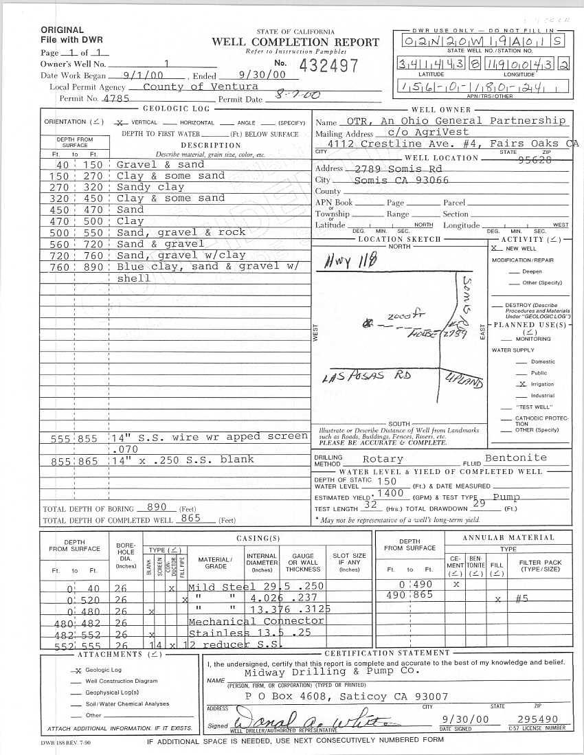
47
48 April 2013 Project No
49 April 2013 Project No
50 April 2013 Project No
51 ATTACHMENT B NPDES PERMIT
52
53
54
55
56
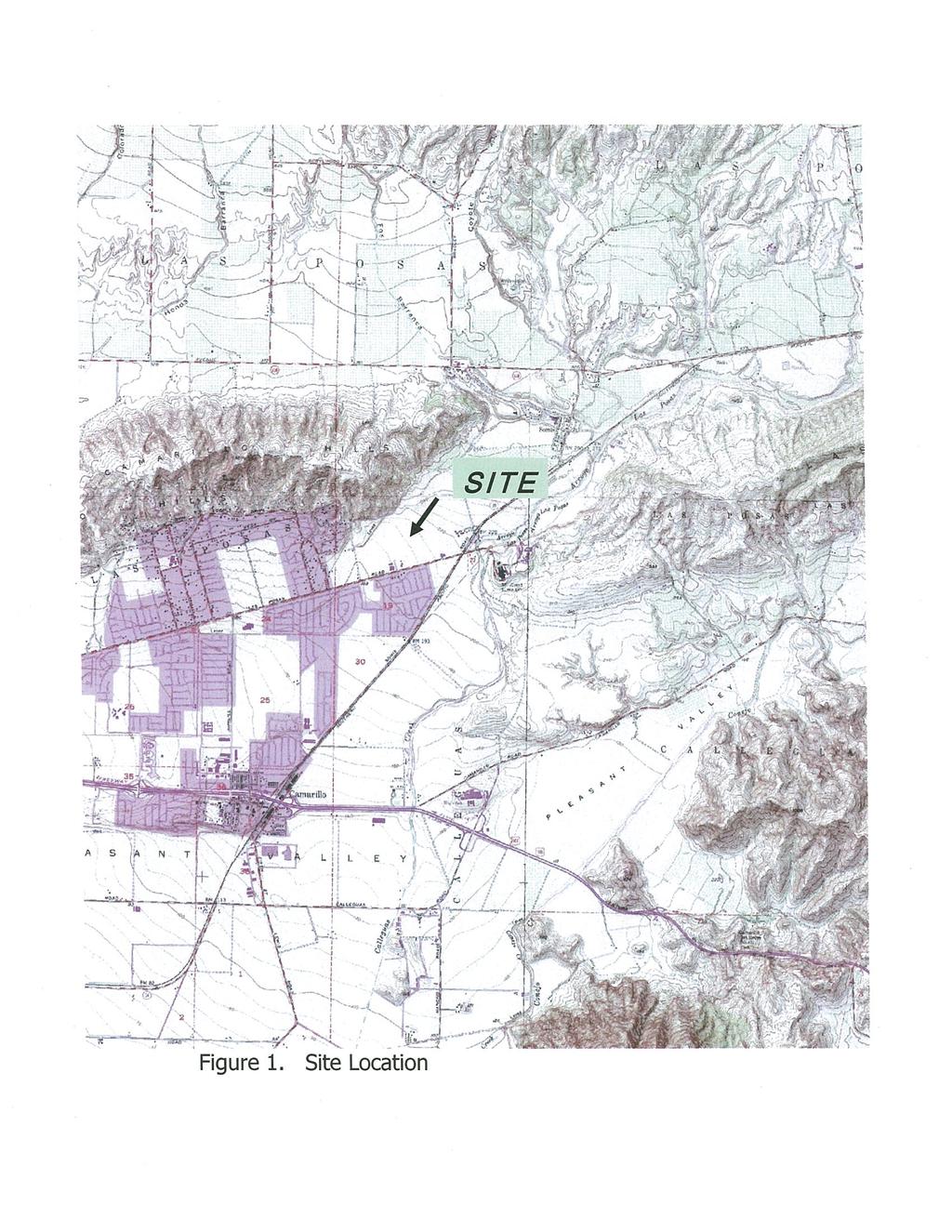
57
58
59
60
61
62
63
64
65
66
67
68
69
70
71
72 ATTACHMENT C PRELIMINARY WELL DESTRUCTION REQUIREMENTS

 The well shall be back-filled with clean sand or gravel to a depth of 40 ft; or debris shall be removed to a depth of 40 ft. 2) Well was drilled under permit and has a proper annular seal.")
73 Ventura County Watershed Protection District Groundwater Section MEMORANDUM DATE: 03/27/13 TO: FROM: Louie Hengehold Barbara Council SUBJECT: ABANDONED WELL, APN Dear Louie, SWN 02N20W19A01S is located on above property. Destruction of this well requires a well permit application and payment of $ permit fee. Preliminary destruction conditions are summarized below. 1) The well shall be back-filled with clean sand or gravel to a depth of 40 ft; or debris shall be removed to a depth of 40 ft. 2) Well was drilled under permit and has a proper annular seal. No perforation of casing is required. 3) Neat cement sealing material shall be placed from a depth of 40 feet to within 5 ft. of ground surface by means of a grout pipe placed to within 2 feet of base of sealing zone. 4) After sealing, casing shall be removed at a depth of 5 feet below ground surface and the work area backfilled with clean fill or native material. As noted, these are preliminary destruction conditions. The permit, when issued, will list complete and confirmed conditions. All work must be done by a licensed well contractor registered to work in Ventura County. A county inspector must be present during perforation and placement of sealing material. This supercedes any previous preliminary conditions. If you have any questions, please feel free to contact me. Regards, Barbara Council Barbara Council Ph: (805)
SPECIFICATIONS - DETAILED PROVISIONS Section Water Well Drilling, Casing & Testing TABLE OF CONTENTS
 SPECIFICATIONS - DETAILED PROVISIONS Section 02734 - Water Well Drilling, Casing & Testing TABLE OF CONTENTS 1.0 GENERAL... 1 1.01 DESCRIPTION... 1 1.02 WELL CONSTRUCTION STANDARDS... 1 1.03 WELL CONSTRUCTION
SECTION GRAVEL PACKED WATER WELL
 SECTION 02520 GRAVEL PACKED WATER WELL PART 1 GENERAL 1.01 SECTION INCLUDES A. Gravel packed water well includes drilling, installing, cleaning, developing, testing, videoing, abandoning, and site clean
5.0 - WATER SUPPLY WELLS
 5.0 - WATER SUPPLY WELLS 5.1. GENERAL This section covers the requirements for public, potable water supply wells. All design, construction, development and testing of any well to be offered for dedication
... Water, Our Most Precious Resource... KaWai A Kline...
 DEPARTMENT OF WATER SUPPLY COUNTY OF HAWAI"I 345 KEKOANAO ' A STREET, SUITE 20 HILO, HAWAI"I 96720 TELEPHONE (808) 961-BOSO FAX (BOB) 961-8657 DEPARTMENT OF WATER SUPPLY COUNTY OF HAWAI'I HILO, HA WAI'I
DIVISION SIX SECTION SPECIAL PROVISIONS SOQUEL CREEK WATER DISTRICT APTOS JUNIOR HIGH REPLACEMENT WELL
 DIVISION SIX SECTION 100 - SPECIAL PROVISIONS SOQUEL CREEK WATER DISTRICT APTOS JUNIOR HIGH REPLACEMENT WELL Section 101 - Intent of Contract Documents Section 102 - Purpose Section 103 - Location Section
Crooked Lake Wellsite P280 Hydrogeological Investigation of the Lower Floridan Aquifer in Polk County, Florida
 SOUTHWEST FLORIDA WATER MANAGEMENT DISTRICT BID NUMBER RFB 1816 CROOKED LAKE WELLSITE PHASE 2 HYDROGEOLOGICAL INVESTIGATION OF THE LOWER FLORIDAN AQUIFER IN POLK COUNTY, FLORIDA FIGURE 1 TECHNICAL SPECIFICATIONS
CHAPTER 39 REQUIREMENTS FOR PROPERLY PLUGGING ABANDONED WELLS
 IAC 5/12/93, 4/8/98 Environmental Protection[567] Ch 39, p.1 IAC 5/12/93, 4/8/98 CHAPTER 39 REQUIREMENTS FOR PROPERLY PLUGGING ABANDONED WELLS 567 39.1(455B) Purpose. The purpose of this chapter is to
CHAPTER 32 - WELL ABANDONMENT ORDINANCE OF DUBUQUE COUNTY, IOWA. Adopted September 5, Part 1 Introduction...2
 CHAPTER 32 - WELL ABANDONMENT ORDINANCE OF DUBUQUE COUNTY, IOWA Adopted September 5, 1989 Table of Contents Page Part 1 Introduction...2 32-1 Purpose...2 32-2 Applicability...2 32-3 Definitions...2 32-4
Soil Improvement by Compaction Grouting
 CITY AND COUNTY OF DENVER ENGINEERING DIVISION Wastewater Capital Projects Management Standard Construction Specification 31-3223.12 Soil Improvement by Compaction Grouting Part 1 - General 1.01 Introduction
SECTION IRRIGATION WATER WELL
 PART 1 GENERAL 1.1 SECTION INCLUDES SECTION 33 21 16 IRRIGATION WATER WELL A. The work shall consist of furnishing all labor, material, equipment, and services necessary for the drilling of irrigation
SUBSURFACE ROTARY DRILLING INVESTIGATION SPECIFICATIONS
 I. SCOPE OF WORK SUBSURFACE ROTARY DRILLING INVESTIGATION SPECIFICATIONS The Department of Environmental Protection, Bureau of Abandoned Mine Reclamation requires a contractor to conduct subsurface rotary
NGWA s Water Well Construction Standard: ANSI/NGWA 01-14
 NGWA s Water Well Construction Standard: ANSI/NGWA 01-14 NGWA Standard Development Process as Approved by ANSI What is ANSI? The American National Standards Institute (ANSI), founded in 1918, promotes
SECTION IRRIGATION WATER WELL
 PART 1 GENERAL 1.1 SECTION INCLUDES: SECTION 02670 IRRIGATION WATER WELL A. The work shall consist of furnishing all labor, material, equipment and services necessary for the drilling of irrigation water
Drilling of grout holes will be measured for payment on the basis of the linear feet of holes actually drilled.
 I - Measurement and payment Mobilization and Demobilization: Payment will be made for costs for assembling all plant and equipment at the site preparatory to initiating the work and for removing it there
REQUEST FOR BIDS WELL DRILLING & TESTING SERVICES I-77 EXIT 1 WATER SYSTEM PROJECT DESCRIPTION
 REQUEST FOR BIDS WELL DRILLING & TESTING SERVICES I-77 EXIT 1 WATER SYSTEM The Carroll County Public Service Authority requests bids from properly licensed well drilling firms, hereafter referred to as
MAINE TURNPIKE AUTHORITY ADDENDUM NO. 2 CONTRACT EXIT 44 SOUTHBOUND ON RAMP IMPROVEMENTS MILE 44.3
 MAINE TURNPIKE AUTHORITY ADDENDUM NO. 2 CONTRACT 2018.03 EXIT 44 SOUTHBOUND ON RAMP IMPROVEMENTS MILE 44.3 The following changes are made to the Proposal, Specifications, and Plans. PROPOSAL Proposal Sheets
Typical Specifications of Compaction Grouting Scope
 Typical Specifications of Compaction Grouting Scope This section covers compaction with Sand/Cement/Flyash grout including the installation of injection pipes. Compaction grouting is sometimes referred
MUD ROTARY TECHNIQUES. MUD Rotary Drilling Method 12/11/2017. Roger E. Renner, MGWC MUD ROTARY DRILLING. Rotary Well Rig
 Roger E. Renner, MGWC MUD ROTARY TECHNIQUES Presenter: Roger E. Renner Master Groundwater Contractor President of E.H. RENNER & SONS, INC. Past President of NGWA 2001 Past President of Minnesota Water
SPECIFICATIONS - DETAILED PROVISIONS Section Water Well Drilling, Casting and Gravel Installation, Development, and Testing C O N T E N T S
 SPECIFICATIONS - DETAILED PROVISIONS Section 02733 - Water Well Drilling, Casting and Gravel C O N T E N T S PART 1 - GENERAL... 1 1.01 DESCRIPTION... 1 1.02 QUALITY ASSURANCE... 1 1.03 RECORDS... 1 1.04
PRODUCTION WELL CONSTRUCTION SPECIFICATIONS. (3) The construction and development of one 450-feet deep Class I water production well
 The construction and development of one 450-feet deep Class I water production well") PRODUCTION WELL CONSTRUCTION SPECIFICATIONS PART 1 - GENERAL 1.1 DESCRIPTION A. Work included covers the following: (1) Pilot hole drilling (2) Furnishing materials (3) The construction and development
PRODUCTION WELL CONSTRUCTION SPECIFICATIONS PART 1 - GENERAL 1.1 DESCRIPTION A. Work included covers the following: (1) Pilot hole drilling (2) Furnishing materials (3) The construction and development
Bi-Directional Static Load Testing of Drilled Shafts
 Supplemental Technical Specification for Bi-Directional Static Load Testing of Drilled Shafts SCDOT Designation: SC-M-712 (9/15) September 2, 2015 1.0 GENERAL This work shall consist of furnishing all
Bi-Directional Static Load Testing of Drilled Shafts
 Supplemental Technical Specification for Bi-Directional Static Load Testing of Drilled Shafts SCDOT Designation: SC-M-712 (01/18) 1.0 GENERAL This work shall consist of furnishing all materials, equipment,
ITEM 416 DRILLED SHAFT FOUNDATIONS Materials. All materials shall conform to the requirements of the pertinent items as follows:
 ITEM 416 DRILLED SHAFT FOUNDATIONS 416.1. Description. This Item shall govern for the construction of foundations consisting of reinforced concrete drilled shafts and/or nonreinforced concrete drilled
California Groundwater Association An NGWA Affiliate State 700 R Street Suite 200 Sacramento, CA
 California Groundwater Association An NGWA Affiliate State 700 R Street Suite 200 Sacramento, CA 95811 cga@groundh2o.org 916-231-2134 CGA STANDARD PRACTICE SERIES ARTICLE 550 MANAGEMENT OF SURFACE ARTESIAN
Addendum No. 1 ASR Monitoring Well Drilling
 Addendum No. 1 ASR Monitoring Well Drilling TMWA Bid No.: 2019-002 TMWA Capital Project No.: 15-0052 September 6, 2018 The following information, clarifications, changes and modifications are by reference
SPECIFICATION : BORING AND JACKING
 SPECIFICATION 330524: BORING AND JACKING PART 1.0 GENERAL 1.1 DESCRIPTION 1.1.1 The work of this specification includes all labor, machinery, construction equipment and appliances required to perform in
GENERAL SPECIFICATION FOR THE REHABILITATION OF SEWERS USING THE THERMOFORM (PVC) PIPE LINING SYSTEM
 PIPE LINING SYSTEM") 1. GENERAL 1.01 DESCRIPTION GENERAL SPECIFICATION FOR THE REHABILITATION OF SEWERS USING THE THERMOFORM (PVC) PIPE LINING SYSTEM A. The Contractor shall furnish all labor, equipment and materials necessary
1. GENERAL 1.01 DESCRIPTION GENERAL SPECIFICATION FOR THE REHABILITATION OF SEWERS USING THE THERMOFORM (PVC) PIPE LINING SYSTEM A. The Contractor shall furnish all labor, equipment and materials necessary
Mid-Basin Injection: Centennial Park Contract MBI
 Mid-Basin Injection: Centennial Park Contract MBI-2017-1 Pre-bid Meeting March 16, 2017 Please Sign-In The contents of this pre-bid presentation are for discussion purposes only and do not supersede the
ITEM NN17 - DRILLED SHAFTS ITEM NN17 - DRILLED SHAFTS (LOW OVERHEAD CLEARANCE) ITEM TRIAL SHAFTS
 ITEM TRIAL SHAFTS") DESCRIPTION A. General. This work shall consist of furnishing the materials and installing drilled shafts at the locations, dimensions, and batters shown on the contract plans or where ordered by the Engineer
DESCRIPTION A. General. This work shall consist of furnishing the materials and installing drilled shafts at the locations, dimensions, and batters shown on the contract plans or where ordered by the Engineer
Multi-Institutional Academic Health Science & Research Center Evansville, IN
 SECTION 02370 AUGER CAST PILES PART 1 - GENERAL 1.1 SECTION INCLUDES: The work covered by these specifications consists of furnishing all labor, equipment and materials for the installation of auger cast
INVESTIGATION RESULTS
 September 13, 2011 Burt Fleischer, R.E.A., R.E.P. Director, Environmental Affairs Hilmar Cheese Company 9001 N. Lander Avenue Hilmar, CA 95324 Subject: Revised Work Plan for Supply Well IN 1 Destruction
SECTION DRILLED CONCRETE PIERS AND SHAFTS
 1 PART ONE - GENERAL 1.1 COORDINATION SECTION 02466 DRILLED CONCRETE PIERS AND SHAFTS A. The General, Supplementary, and Special Conditions of these specifications shall all be considered as a part of
BID PROPOSAL PROPOSAL OF, corporation, a partnership consisting of, an individual doing business as,
 Access Roads BID PROPOSAL PROPOSAL OF, corporation, a partnership consisting of, an individual doing business as, THE SAN ANTONIO WATER SYSTEM: Pursuant to Instructions and Invitations to Bidders, the
SECTION 13 - EXISTING FACILITIES TABLE OF CONTENTS
 SECTION 13 - EXISTING FACILITIES TABLE OF CONTENTS Section Page 13-1 GENERAL... 13.1 13-1.01 Preservation of Property... 13.1 13-1.02 Overloading, Pavement Protection & Repair... 13.1 13-2 REMOVING EXISTING
SECTION BORING AND/OR JACKING PIPE
 02910-1 of 6 SECTION 02910 BORING AND/OR JACKING PIPE 02910.01 GENERAL A. Description Boring and/or jacking pipe shall include, but not necessarily be limited to, furnishing and installing carrier pipe
Wastewater Capital Projects Management Standard Construction Specification
 CITY AND COUNTY OF DENVER ENGINEERING DIVISION Wastewater Capital Projects Management Standard Construction Specification 7.4 PERMEATION GROUTING 7.4.1 Definitions 7.4.1.1 Geotechnical Data Report (GDR)
SECTION DUCTILE IRON PILES
 SECTION 31 66 13 DUCTILE IRON PILES PART 1 - GENERAL 1.1 GENERAL REQUIREMENTS A. Work of this Section, as shown or specified, shall be in accordance with the requirements of the Contract Documents. B.
SECTION SPECIAL PROVISIONS SOQUEL CREEK WATER DISTRICT TWIN LAKES CHURCH SEAWATER INTRUSION PREVENTION PILOT WELL
 SECTION 600 - SPECIAL PROVISIONS SOQUEL CREEK WATER DISTRICT TWIN LAKES CHURCH SEAWATER INTRUSION PREVENTION PILOT WELL SECTION 601 - SECTION 602 - SECTION 603 - SECTION 604 - SECTION 605 - SECTION 606
TECHNICAL SPECIFICATIONS SOUTH MARTIN REGIONAL UTILITY
 TECHNICAL SPECIFICATIONS SOUTH MARTIN REGIONAL UTILITY CONSTRUCTION AND TESTING OF SURFICIAL AQUIFER REPLACEMENT PRODUCTION WELL N15R AND REMEDIATION WELL R-4 HOBE SOUND, FLORIDA Submitted by: 4/2019 CONSTRUCTION
of GENERAL. A. Description
 02920-1 of 11 SECTION 02920: EARTH TUNNELING 02920.01 GENERAL A. Description Earth tunneling shall include, but not necessarily be limited to, constructing earth tunnels and furnishing and installing tunnel
Rapid Axial Load Testing of Drilled Shafts
 Supplemental Technical Specification for Rapid Axial Load Testing of Drilled Shafts SCDOT Designation: SC-M-712 (9/15) September 4, 2015 1.0 GENERAL This work shall consist of performing a rapid axial
ADDENDUM 1 January 29, 2016
 SAWS Gonzales County Saturn Well Project Solicitation Number: B-16-001-GC Job No.: 15-0130 To Respondent of Record: ADDENDUM 1 January 29, 2016 This addendum, applicable to work referenced above, is an
SAMPLE GUIDE SPECIFICATIONS FOR OSTERBERG CELL LOAD TESTING OF DRILLED SHAFTS
 SAMPLE GUIDE SPECIFICATIONS FOR OSTERBERG CELL LOAD TESTING OF DRILLED SHAFTS 1.0 DESCRIPTION This work shall consist of furnishing all materials and labor necessary for conducting an Osterberg Cell (O-cell)
Case Study Casing Path Well An Effective Method to Deal with Cascading Water
 Roscoe Moss Company Technical Memorandum 004-5 Case Study Casing Path Well An Effective Method to Deal with Cascading Water Executive Summary Air entrainment can be a serious problem with the potential
III. TECHNICAL SPECIFICATIONS DIVISION 56 BORED PIPE
 III. TECHNICAL SPECIFICATIONS DIVISION 56 BORED PIPE PART I - GENERAL 56.01 SCOPE: The Contractor shall furnish all labor, material, equipment and supplies and shall perform all work necessary for the
Environmental Management Chapter
 Environmental Management Chapter 335-9-1 ALABAMA DEPARTMENT OF ENVIRONMENTAL MANAGEMENT WATER DIVISION - WATER WELL STANDARDS PROGRAM ADMINISTRATIVE CODE CHAPTER 335-9-1 LICENSING AND CERTIFICATION OF
CCU Engineering Specifications. Section PIPE REMOVAL, DISPOSAL, ALTERATION, MODIFICATION OR PIPE ABANDONMENT
 CCU Engineering Specifications Section 002310 PIPE REMOVAL, DISPOSAL, ALTERATION, MODIFICATION OR PIPE ABANDONMENT Effective Date: Nov. 1st, 2011 Page 1 of 5 PART 1 - GENERAL The following specification
AWWA CA NV Section Spring Conference Sacramento March 24, :30 AM 9:00 AM Session 22 Water Well Technology
 AWWA CA NV Section Spring Conference Sacramento March 24, 2016 8:30 AM 9:00 AM Session 22 Water Well Technology Drilling Fluid from an Owner/Consultant Perspective Larry Ernst, PG, CEG, CHG Principal Hydrogeologist
1. All underground utilities under railroad tracks shall be encased in a larger pipe or conduit called the casing pipe.
 MTS Jack and Bore Design Criteria Note: For the purposes of this Design Criteria and subsequent Construction Notes, the term Jack and Bore is used generically to refer to a number of trenchless construction
Subject: Aquifer Test Observation Well Installation Work Plan Hilmar Cheese Company, Hilmar, Merced County, CA
 October 1, 2009 Mr. Jan Alfson California Regional Water Quality Control Board Fresno Branch Office 1685 E Street Fresno, CA 93706 Subject: Aquifer Test Observation Well Installation Work Plan Hilmar Cheese
SECTION XXXXX AGGREGATE PIERS PART 1 - GENERAL
 SECTION XXXXX AGGREGATE PIERS PART 1 - GENERAL 1.1 RELATED DOCUMENTS: Drawings and general provisions of the Contract, including General and Supplementary Conditions and other Division 00 and Division
TECHNICAL SPECIFICATION BIO-POLYMER SLURRY DRAINAGE TRENCH CONSTRUCTION GROUNDWATER COLLECTOR TRENCH
 TECHNICAL SPECIFICATION BIO-POLYMER SLURRY DRAINAGE TRENCH CONSTRUCTION GROUNDWATER COLLECTOR TRENCH (This technical specification is to be used to guide the writer in the contract requirements for Bio-Polymer
SECTION GEOTECHNICAL INSTRUMENTATION
 SECTION 13510 GEOTECHNICAL INSTRUMENTATION PART 1 GENERAL 1.1 WORK INCLUDED A. This section covers the work necessary for furnishing and installing new piezometers, movement monuments, and inclinometers
SPECIAL SPECIFICATION 4492 Tie Back Anchors
 2004 Specifications CSJ 0504-02-022 SPECI SPECIFICATION 4492 Tie Back Anchors 1. Description. This Item shall govern for the installation of tie-back anchors in place, with grouting as required in accordance
STANDARD SPECIFICATION FOR MICROPILE CONSTRUCTION
 Section 67.0 Knoxville, Tennessee March 2013 1. Description STANDARD SPECIFICATION FOR MICROPILE CONSTRUCTION a) This work shall consist of constructing micropiles as shown on the Contract plans in accordance
1993 Specifications CSJ SPECIAL SPECIFICATION ITEM 4417 DEWATERING IN CONTAMINATED GROUNDWATER
 1993 Specifications CSJ 8015-24-003 SPECIAL SPECIFICATION TO ITEM 4417 DEWATERING IN CONTAMINATED GROUNDWATER 1. DESCRIPTION. This item shall govern all work required to remove groundwater encountered
UPRR INDUSTRIAL LEAD BRIDGE T-WALL RETAINING WALL SYSTEM 5.0 x 7.5 UNITS DESIGN UNIT 018 WORK PACKAGE 04
 UPRR INDUSTRIAL LEAD BRIDGE T-WALL RETAINING WALL SYSTEM 5.0 x 7.5 UNITS DESIGN UNIT 018 WORK PACKAGE 04 1. Description This work shall consist of the design, manufacture and construction of a T-WALL structure
CHAPTER 5 WELL CONSTRUCTION
 CHAPTER 5 WELL CONSTRUCTION Wells Shallow ( < 15 meters) Deep ( > 15 meters) Shallow Wells Include Dug wells Kanats Vertical wells Horizontal wells They are drilled by: digging, boring, driving, and jetting
SECTION SUBSURFACE INVESTIGATION. 1. Protection of the environment; Section
 02011-1 of 5 SECTION 02011 SUBSURFACE INVESTIGATION 02011.01 GENERAL A. Description Subsurface investigation shall include, but not necessarily be limited to, drilling test holes (in rock), auguring holes,
Design Checklist for EWB-USA Chapters Working on Drilled Well
 Design Checklist for EWB-USA Chapters Working on Drilled Well TAC Review for Phase 2 Borehole development and aquifer evaluation The following checklist provides a list of specific information that must
North End and South End Section Hauled Wastewater Receiving Facilities Page 1 Bid Opportunity No
 Hauled Wastewater Receiving Facilities Page 1 Part 1 General 1.1 SECTION INCLUDES.1 Materials and installation for sewage force mains. 1.2 RELATED SECTIONS.1 CW 2110 Watermains and all specifications referenced
DIVISION II TECHNICAL SPECIFICATIONS SECTION S-003 SANITARY SEWER FORCE MAIN SYSTEM
 DIVISION II TECHNICAL SPECIFICATIONS SECTION S-003 SANITARY SEWER FORCE MAIN SYSTEM TABLE OF CONTENTS: I. DESCRIPTION:... 2 II. COORDINATION:... 2 III. CONSTRUCTION LAYOUT:... 3 IV. MATERIALS:... 3 V.
TRENCHLESS CONSTRUCTION (BORING, JACKING, AND TUNNELING)
") PART 1 - GENERAL TRENCHLESS CONSTRUCTION (BORING, JACKING, AND TUNNELING) 1.01 SECTION INCLUDES A. Trenchless Installation of Carrier Pipe with Casing Pipe B. Trenchless Installation of Carrier Pipe without
PART 1 - GENERAL TRENCHLESS CONSTRUCTION (BORING, JACKING, AND TUNNELING) 1.01 SECTION INCLUDES A. Trenchless Installation of Carrier Pipe with Casing Pipe B. Trenchless Installation of Carrier Pipe without
Water Well Drilling Agreements
 For more information refer to the Water Wells That Last video (Part I Planning and Construction). Water Well Drilling Agreements This module outlines a checklist of items that you and your licensed water
SECTION DRILLED CONCRETE PIERS AND SHAFTS
 SECTION 31 63 29 PART 1 - GENERAL 1.1 RELATED DOCUMENTS A. Drawings and general provisions of the Contract, including General and Supplementary Conditions and Division 01 Specification Sections, apply
ITEM 432 TUNNEL CONSTRUCTION
 AFTER MARCH 1, 2012 ITEM 432 TUNNEL CONSTRUCTION 432.1 Description. This Item shall govern for tunnel lines under railroads, state highways, and concrete paved streets or other obstructions indicated.
SUPPLEMENTAL TECHNICAL SPECIFICATION
 July 14, 2015 HIGH STRAIN DYNAMIC LOAD TESTING OF DRILLED SHAFTS 1.0 GENERAL This work shall consist of performing high-strain dynamic testing using a drop weight loading system on a test drilled shaft
703 - DRILLED SHAFTS SECTION 703 DRILLED SHAFTS
 SECTION 703 DRILLED SHAFTS 703.1 DESCRIPTION Construct drilled shafts by the cased or uncased method depending upon site conditions and Contract Document requirements. BID ITEMS Drilled Shaft (*) (**)
INDEX FOR SPECIFICATIONS FOR JACKING CULVERTS THROUGH EMBANKMENTS SCOPE... 2
 INDEX FOR SPECIFICATIONS FOR JACKING CULVERTS THROUGH EMBANKMENTS 410. 1 SCOPE... 2 410. 2 DEFINITIONS 2.1 Tunneling and Jacking... 2 2.2 Tunneling... 2 2.3 Jacking... 2 410. 3 MATERIALS 3.1 General...
SECTION 807 PUMP STATION REHABILITATION
 SECTION 807 PUMP STATION REHABILITATION 807-1 DESCRIPTION: Rehabilitation of pump stations shall be defined as the cleaning, removal, repair and/or replacement of any and/or all components including but
STANDARD SPECIFICATIONS SECTION BORING AND JACKING. A. Section includes requirements for boring and jacking casing pipe.
 STANDARD SPECIFICATIONS SECTION 02445 BORING AND JACKING PART 1 GENERAL 1.1 DESCRIPTION A. Section includes requirements for boring and jacking casing pipe. 1.2 DEFINITIONS A. Carrier Pipe: Sewer or water
Identification. Module 4 Water Well Drilling Agreements
 For more information refer to the Water Wells That Last video series Part I Planning and Construction. + Water Well Drilling Agreements This module outlines a checklist of items that you and your drilling
SECTION HORIZONTAL DIRECTIONAL DRILLING
 SECTION 330532- HORIZONTAL DIRECTIONAL DRILLING PART 1 - GENERAL 1.1 DESCRIPTION A. Furnish all labor, materials, tools, and equipment required to install pipes below the outer perimeter prison fence using
SECTION 39 - MANHOLES TABLE OF CONTENTS
 Section SECTION 39 - MANHOLES TABLE OF CONTENTS Page 39-1 GENERAL... 39.1 39-2 CONCRETE MANHOLES... 39.1 39-2.01 NOT USED... 39.1 39-2.02 Concrete Storm Drain Manholes... 39.1 39-3 SADDLE SEWER MANHOLES...
SPECIAL SPECIFICATION 5989 Settlement Gauge
 2004 Specifications CSJ 0047-14-067 SPECIAL SPECIFICATION 5989 Settlement Gauge Description. Install, maintain, and subsequently abandon settlement gauges as indicated for the purpose of obtaining foundation
STANDARD SPECIFICATION Section Auger-Grout Injected Piles Civil Engineering Group Revised: August, 2000
 DIVISION 2: SITE WORK SECTION 02320 AUGER-GROUT INJECTED PILES STANDARD SPECIFICATION PART 1 GENERAL 1.0 DESCRIPTION OF WORK This work shall include all excavation, concrete, equipment and accessories
REGIONAL CONSTRUCTION STANDARDS
 REGIONAL CONSTRUCTION STANDARDS SIXTH EDITION Publication Update 6.5 (Full Committee Approved Proposed Revision 6.5 Storm Sewer Joint Wrap - Section 302 As Publication Update 6.5) March 27, 2018 Copyright
ADDENDUM 2 CHINO DESALTER AUTHORITY CHINO CREEK WELLFIELD WELLS I-19, I-20 AND I-21 CONSTRUCTION CDA SPEC NO. CDAEXP
 ADDENDUM 2 CHINO DESALTER AUTHORITY CHINO CREEK WELLFIELD WELLS I-19, I-20 AND I-21 CONSTRUCTION CDA SPEC NO. CDAEXP3-12-01 The following ADDENDUM 2 shall be made part of the Notice Inviting Bids with
TRENCHLESS CONSTRUCTION (BORING, JACKING, AND TUNNELING)
") PART 1 - GENERAL TRENCHLESS CONSTRUCTION (BORING, JACKING, AND TUNNELING) 1.01 SECTION INCLUDES A. Trenchless Installation of Carrier Pipe with Casing Pipe B. Trenchless Installation of Carrier Pipe without
PART 1 - GENERAL TRENCHLESS CONSTRUCTION (BORING, JACKING, AND TUNNELING) 1.01 SECTION INCLUDES A. Trenchless Installation of Carrier Pipe with Casing Pipe B. Trenchless Installation of Carrier Pipe without
SECTION MONITORING WELL ABANDONMENT
 SECTION 027300 MONITORING WELL ABANDONMENT PART I GENERAL 1.01 GENERAL PROVISIONS A. Attention is directed to the CONTRACT AND GENERAL CONDITIONS and all Sections within DIVISION 1 - GENERAL REQUIREMENTS,
Case Study A Comparison of Well Efficiency and Aquifer Test Results Louvered Screen vs. Continuous Wire-Wrapped Screen Big Pine, California
 Case Study A Comparison of Well Efficiency and Aquifer Test Results Louvered Screen vs. Continuous Wire-Wrapped Screen Big Pine, California Executive Summary Aquifer test results demonstrated that the
SECTION 920 SANITARY AND STORM SEWER MANHOLES
 SECTION 920 SANITARY AND STORM SEWER MANHOLES 920.1 GENERAL This section contains items which are relative to the installation of sanitary and storm sewer manholes. 920.2 REFERENCES 920.2.1 ASTM C 43 C
Stormwater Standards. Clackamas County Service District No. 1. Infiltration Testing Guide
 Stormwater Standards Clackamas County Service District No. 1 APPENDIX E Infiltration Testing Guide Table of Contents Appendix E - Infiltration Testing Guide... Page E.1 General... 1 E.2 Basic Method -
SCOPE OF WORK FOR PILING JOB
 SCOPE OF WORK FOR PILING JOB 1.0 PURPOSE This document defines the scope of works and specific requirements for the tank pad construction including pile foundation system for the proposed tanks at Wadala
Water Well Decommissioning Guidelines
 Water Well Decommissioning Guidelines Approval Date: June 1, 2007 Effective Date: September 10, 2007 Approved By: Gerard MacLellan Version Control: This is a new guideline I. Introduction The Water Well
Lantz-Boggio Architects, P.C LBA Project No
 SECTION 313430- PART 1 GENERAL 1.1 WORK INCLUDED A. Provide all equipment, material, labor and supervision to design and install Engineered Aggregate Piers for the soil reinforcement. Design shall rely
SECTION 14 - RESTORATION OF SURFACES TABLE OF CONTENTS
 SECTION 14 - RESTORATION OF SURFACES TABLE OF CONTENTS Section Page 14-1 GENERAL... 14.1 14-2 PRIVATE ROADS... 14.1 14-3 STREETS AND PARKING LOTS... 14.1 14-3.01 Aggregate Base... 14.1 14-3.02 Asphalt
Procedures for Connecting to Central Sewer System
 Procedures for Connecting to Central Sewer System These procedures and requirements are taken from the Taney County Regional Sewer District s appoved Sewer Use Regulation, Article 4 Building Sewers and
SECTION PRODUCTION WELLS. 1. Protection of the Environment; Section
 SECTION 02555 02555-1 of 18 PRODUCTION WELLS 02555.01 GENERAL A. Description Water production wells will be double cased, lap or fully double cased construction, drilled by the mud rotary or reverse rotary
ITEM 430 CONSTRUCTION OF UNDERGROUND UTILITIES
 AFTER MARCH 1, 2012 ITEM 430 CONSTRUCTION OF UNDERGROUND UTILITIES 430.1 Description. This item shall govern for all excavation required for the construction of sewers, sewer structures, pipe culverts,
SECTION 39 - MANHOLES TABLE OF CONTENTS 39-1 GENERAL PRECAST CONCRETE MANHOLES
 Section SECTION 39 - MANHOLES TABLE OF CONTENTS 39-1 GENERAL... 39-1 39-2 PRECAST CONCRETE MANHOLES... 39-1 39-2.01 Precast Concrete Storm Drain Manholes... 39-1 39-3 SADDLE MANHOLES... 39-2 39-3.01 Saddle
SECTION MEASUREMENT AND PAYMENT
 SECTION 01026 PART 1 GENERAL 1.1 SECTION INCLUDES A. Explanation and Definitions B. Measurement C. Payment D. Schedule of Values E. Application for Payment 1.2 EXPLANATION AND DEFINITIONS A. The following
Solicitation Number: CO Job No.:
 Solicitation Number: CO 00169 Job No.: 17 6008 4/12/18 To Bidder of Record: This addendum, applicable to work referenced above, is an amendment to the bid proposal, plans and specifications and as such
DEFINITIONS. A shallow bored hole under the derrick substructure in which the kelly is temporarily stored during tripping operations.
 DEFINITIONS 1. Conductor Hole A large diameter hole bored to facilitate steel pipe. May be cemented in place to allow conventional oil and gas well drilling operations,and also allows fluid returns to
ITEM 481 MONOLITHIC REINFORCED CONCRETE BOX SEWERS
 AFTER FEBRUARY 1, 2011 ITEM 481 MONOLITHIC REINFORCED CONCRETE BOX SEWERS 481.1 Description. This specification shall govern for the construction of monolithic, reinforced concrete box sewers of the size,
Handbook of Ground Water Development
 Handbook of Ground Water Development PREFACE There has been a long-standing need for a comprehensive book on ground water development. The lack of sufficient texts may be because the industry is highly
PROPOSED REGULATION OF THE STATE ENGINEER. LCB File No. R May 1, 2012
 PROPOSED REGULATION OF THE STATE ENGINEER LCB File No. R039-12 May 1, 2012 EXPLANATION Matter in italics is new; matter in brackets [omitted material] is material to be omitted. AUTHORITY: 1-10, 12-16
Florence County Government
 Florence County Government Procurement Department April 29, 2016 ADDENDUM NO.1- CONSTRUCTION OF A BOARDWALK AND FISHING PIERS AT LAKE CITY PARK PROJECT (BID NO. 35-15/16) The following changes shall be
B. Subsurface data is available from the Owner. Contractor is urged to carefully analyze the site conditions.
 SECTION 31 23 33 - TRENCHING, BACKFILLING AND COMPACTION PART 1 - GENERAL 1.1 SCOPE A. This Section specifies the requirements for excavating and backfilling for storm sewer, sanitary sewer, water distribution
DIVISION 33 - UTILITIES SECTION UTILITY PIPE BORING AND JACKING DIVISION 33 UTILITIES SECTION UTILITY PIPE BORING AND JACKING
 DIVISION 33 UTILITIES PART 1 GENERAL 1.01 SCOPE A. This work shall consist of the underground construction of a pipeline across the state right-ofway, or other facility as indicated on the plans and as