Case Study: Considerations for Applying the Triad Approach at the Hartford Hydrocarbon Plume Site, Hartford, Illinois
|
|
|
- Ronald Evans
- 5 years ago
- Views:
Transcription
1 Case Study: Considerations for Applying the Triad Approach at the Hartford Hydrocarbon Plume Site, Hartford, Illinois Vapor Intrusion Mitigation and Product Recovery System Design DP-1 1
2 Problem Statement!48 historical hydrocarbon fuel spills from surrounding pipelines and storage tanks!fires and odors have been reported by residences particularly during spring!increased vapor intrusion is presumed to be caused by raising water levels carrying hydrocarbon vapors into utility corridors during high stands of the river!release of hydrocarbons to surface water DP-2 2
3 Case Study Overview! Site History! Preliminary CSM for the site! Refining the CSM using dynamic work strategies and real time measurements! The CSM for product removal! Potential product removal strategies! The CSM for vapor intrusion! Potential vapor mitigation strategies! Current project status and lessons learned DP-3 3
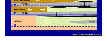
4 Preliminary CSM - Site Geology!Shallow discontinuous sands capped by silts and clays!discontinuous sands and silts grade into more massive channel type sands!structural features created by periodic river avulsions!complex interconnectivity between sands and structures DP-4 4
5 DP-5 5

6 DP-6 6

7 DP-7 7

8 DP-8 8


9 DP-9 9
10 Refining the CSM using Dynamic Work Strategies and Real Time Measurements!ROST TM used along with soil borings to define the nature and extent of product across the site!nested vapor probes, subslab probes, active sewer soil gas monitoring and real time devices used to define vapor plumes based on the presence or absence of product in surface and subsurface soil!dissolved phase investigation being conducted using direct push grab groundwater sampling methods DP-10 10

11 DP-11 11
12 DP-12 12
13 DP-13 13
14 DP-14 14
15 DP-15 15
16 DP-16 16
17 Important Observations from ROST TM Investigation!Thick zones of product not always associated with identified surface releases!three distinct product types found across the site!distribution of product appears to be controlled by structural features and clay thickness!changes in water level has created a large smear zone that could control apparent product thicknesses and thus product removal efficiency DP-17 17
18 Product Recovery CSM Less Than Obvious LNAPL Plume Characteristics!Initial head and not necessarily groundwater gradients will control plume configurations!porosity, percent hydrocarbon saturation, and capillary pressures control mobility!plumes tend to reach equilibrium and then remain in a steady state!standard methods for prediction of potential for recovery may be inadequate without empirical testing and the right information/data DP-18 18

19 Typical LNAPL Release Release Source Vadose Zone Capillary Fringe Water Table LNAPL Dissolved Phase Capillary Fringe Water Table DP-19 NEXT Petroleum hydrocarbons can be released to the subsurface, through spills and leaking pipelines, underground storage tanks, and above ground storage tanks. Released liquids migrate downward primarily by gravity through the vadose zone, the unsaturated or partially saturated subsurface media above the water table. The unconsolidated porous media in the vadose zone consist of both solid material and voids, called pore spaces. These pore spaces are filled primarily with air and small amounts of water. The bottom part of the vadose zone is called the capillary fringe and is partially saturated with water pulled upward by capillary forces from the underlying saturated zone. Water pressure in the saturated zone is greater than atmospheric pressure, and water generally fills the pore space. Water in this zone is called groundwater. As LNAPL migrates through the vadose zone toward the capillary fringe, it displaces air, but generally not water, from the pore spaces. The LNAPL-filled pores drain slowly and can leave behind LNAPL-globules trapped by capillary forces. If only a small volume of LNAPL is released, it may become entirely trapped in the vadose zone. If a greater volume is released, the LNAPL may migrate completely through the unsaturated zone and accumulate in a zone that is loosely constrained by the water table. When LNAPL reaches the capillary fringe, it begins to displace water in the pore spaces. The amount of water displaced and the resulting volume of LNAPL in the soil is a primary focus of this training. At the end of the training, you will be able to determine the volume of LNAPL in the capillary fringe at and below the water table. It is known that LNAPL in the water table acts as a long-term source for the dissolved plume. While dissolution will not be addressed in this course, it should be noted that maximizing hydraulic LNAPL recovery to the extent practical is not likely to reduce the risk at a site but, in certain, circumstances may reduce the life of the risk. The longevity reduction, however, may not have practical significance. 19
20 Capillary Pressure H c As pore size gets smaller, capillary rise gets bigger. H wt DP-20 Capillary pressure is defined as the pressure in the nonwetting phase minus the pressure in the wetting phase. When tubes of different diameters are placed in a dish containing water, the water will rise in each tube in relation to the surface tension between the air and the water, the contact angle (the angle between the surface of the water and surface of the tube), and the radius of the tube. As pore size gets smaller (reflected in the smallerdiameter tubes above), the capillary rise gets bigger meaning that the capillary pressure is higher. When water wets the surface of the tube, the contact angle is unity. The capillary rise is balanced by the pressure from the height of the column of water. You can view this another way as well. In porous media, the smallest pores will take in the water first and hold it the tightest. It takes significant pressure to get the water out of the smallest pores. This is why coarse sands and gravels have a relatively small capillary fringe, while silts and clay have a large capillary fringe (and hence, stay moist). NOTE: Capillary pressure is often referred to as capillary suction pressure, because the wetting phase is sucked up the tube. The terms are interchangeable. 20
21 Example: Simulated LNAPL Release Release Area Year 1 Year 5 Year 56 Contour Interval = 0.2 m with plume delineated at m 0 50 Scale (m) 100 DP-21 NEXT This figure shows the simulated migration of a plume of about 1,500 m 3 of LNAPL over 56 years. The images represent predicted well product thickness measurements. While growth in the plume from release to Year 1 is clear, the plume appears to grow only slightly over the next 56 years. Certainly, the small gradient, which produces a low groundwater flow rate, has had an effect, but groundwater has moved about 600 meters over the 56 years. The LNAPL plume, however, has not. 21
22 DP-22 22
23 DP-23 23
24 CSM for Product Removal! Product plume appears to be stable and range from diesel to gasoline, but ongoing releases are occurring! Well screened intervals and geology will control the apparent thickness in wells» If clay present above water table then rise in water table should improve apparent thickness and improve recovery» If no clay present above water table then apparent thickness should decrease with rise in water table! Dual Phase extraction most likely candidate, but will be complicated by groundwater fluctuations DP-24 24
25 Current Product Removal Related Activities!A mobile dual phase system is being used to evaluate removal rates!additional physical data is being collected to evaluate percent saturation, porosities, viscosity, and distribution to develop a clearer picture of where and if more permanent systems should be installed DP-25 25
26 Vapor Intrusion Mitigation CSM - Challenges!Vapor intrusion seems to be worst when water levels rise!indoor air evaluation complicated by access issues and household contamination!soil gas analysis complicated by presence of clays near surface!utility corridors vary in integrity and material used to backfill DP-26 26
27 DP-27 27
28 DP-28 28
29 DP-29 29
30 DP-30 30
31 The CSM and Vapor Related Issues! Vapors» Thinning in clays and structural highs seem to control where vapor intrusion is greatest above fuel spills not associated with surface releases» Near surface releases into thicker clay zones tend to correspond with increased vapors» Lateral migration of vapors possible in sand zones away from product plume in unsaturated zone» Utility corridors in contact with sands a potential preferred pathway DP-31 31

32 DP-32 32

33 DP-33 33
34 DP-34 34
35 Vapor Mitigation Strategy!Regional SVE system design and optimization is planned because of results obtained from community center pilot!silty clay seems to limit direct exposure to vapors under most conditions and enhance the effectiveness/radius of influence of SVE system!utility systems will be sealed and otherwise mitigated prior to entry into homes DP-35 35
36 Current Site Activities and Status!The technology support center is working with START and the Hartford Working group to design and evaluate the planned SVE and product removal system!data collection efforts will be focused on collecting the data needed to support design of both a mobile and hardwired product removal system designed to adapt to changing water levels at the site DP-36 36
37 Lessons Learned! Building a comprehensive CSM lead to efficient data collection and group consensus! House fans not a good vapor mitigation method under some circumstances! Passive and active soil gas does not necessarily provide reliable data at large petroleum sites! The geology, hydrogeology, and contaminant characteristics at a site can be used to predict vapor issues and product recovery systems! LNAPL sites do not always conform with our preconceived notions of how contaminants behave DP-37 37
38 LNAPL Assessment Suggestions for Product Removal (additional info)!obtaining Core Samples!Preserving Core Samples!Laboratory Measurements»Soils: Saturation & Capillary Pressure»Fluids: Interfacial Tensions, Viscosity, Density!Laser-Induced Fluorescence DP-38 Now that you have a basic understanding of LNAPL behavior in the subsurface, let s move on to discuss some of the methods and techniques available to help in assessing a LNAPL site. These include methods for obtaining and preserving core samples, laboratory methods for soils and fluids, and a technique known as laserinduced fluorescence (LIF). LIF can provide a semi-quantitative vertical distribution of LNAPL occurrence. LIF response is a function of media and LNAPL properties, and some experts have correlated LIF response and LNAPL saturation. Solid media and fluid property measurements from ASTM International, API, and other organizations can provide additional information and are available on the API web site at 38
39 Obtaining Core Samples! Preferred Situation» Existing well containing product has been cored.» Geology and depth of likely LNAPL occurrence are known.! Data Noted in Boring Log:» Percent gravel, sand and fines» Water content» Odor» Soil structure» Signs of LNAPL» PID/FID values» Sampling data (to 5 feet below deepest LNAPL penetration or lower boundary unit)! Further Sampling Locations Based on Data Obtained DP-39 Core samples should be obtained for measuring LNAPL saturation, capillary pressure, and, in some cases, relative permeability. Cores can be photographed to study the heterogeneities and location of LNAPL. (LIF and cone penetrometer technology, or CPT, data also can be used to locate LNAPL and study media heterogeneity.) The procedure outlined in the next three slides is for an ideal situation, one in which there are no cost restrictions. Using this procedure, the cost for a couple of borings with the associated core and fluid property tests is likely to be a minimum of about $5,000. Note that bringing undisturbed cores to the surface, especially in sands, can be very difficult. So, taking extra care to recover good cores can help you manage cost. The preferred situation, as shown above, is one in which an existing well containing product has been cored, and the geology and depth of likely LNAPL occurrence are known. You might obtain information on LNAPL depth of occurrence from a high photoionization detector (PID)/flame ionization detector (FID) reading. If this is not the case, a very careful boring log should be produced noting the percent gravel, sand, and fines; the water content; the odor; the soil structure; and signs of LNAPL. PID/FID values also should be noted. (The frequency of PID/FID data collection is up to the site geologist, who responds to field conditions. In a boring with a lot of LNAPL, PID/FID measurements should be made each foot. Fewer measurements can be made when less LNAPL is present.) Core samples should be taken to at least 5 feet below depth of LNAPL penetration or until a very competent lower boundary unit is encountered. (Sometimes, LIF, is used instead of boring.) Use the information gathered to decide the location for additional boring or use of another undisturbed sampling method (e.g., Shelby Tube samples) across the area of LNAPL impact. For shallow investigations (<50 feet), dual-tube direct push rigs also may be an efficient way to collect continuous cores. 39
40 Preserving Core Samples! To remove core from sampler:» If core in sleeves Fill any void with plastic wrap, Seal with Teflon film, Tape on plastic end caps.» If core not in sleeves Slide gently from sampler onto split PVC core supports, Wrap with plastic and secure with clear box tape.! Label each core section with top and bottom depths.! Label multiple sleeves sequentially (A, B, C... etc.) starting with the top or most shallow sleeve.! Immediately pack cores with ice or freeze with liquid nitrogen to minimize migration of core fluids.! Ship cores at end of each day by overnight courier. DP-40 Cores are typically preserved following the procedure outlined here; however, the procedure may vary, depending on the individuals and the laboratories involved. To start, remove the core from the sampler as soon as possible. If the core is in sleeves, fill any void space with plastic wrap to minimize core movement. Seal the core with Teflon film and tape on plastic end caps. If the core is not in sleeves, gently slide it from the sampler onto split PVC core supports. Wrap the core with plastic wrap, and secure it with clear box tape. Each core section should be labeled with top and bottom depths. Fractions of a foot should be recorded in tenths. Multiple sleeves should be labeled sequentially (A, B, C, etc.), starting with the top or most shallow sleeve. Immediately place the cores in a cooler containing dry ice to minimize the movement of core fluids. As alternatives, you can put the core into a cooler with frozen Blue Ice packs and foam packing material, or you can freeze it with liquid nitrogen. Ship the cores at the end of each day by overnight courier. 40
41 Core Testing When LNAPL Present! Photograph cores in normal light and UV.! Perform saturation analyses where there are LNAPLs. DP-41 Earlier discussions regarding LNAPL saturation were intended to define what it is and to describe the processes that influence it. This slide begins to discuss how LNAPL saturation is measured. The objective of core testing is to determine the solid media-fluid interaction properties that will enable us to predict LNAPL saturation and conductivity in the subsurface. If good saturation measurements are obtained, we can compare theory with experiment and improve our confidence in the predictions. Remember, each site is different, and the project team will have to decide how many samples are needed for analysis at your site. Soil samples for laboratory testing are selected based on soil classification and LNAPL type. Soil-fluid interaction properties such as capillary pressure and relative permeability are affected by the soil structure (e.g., porosity and pore size distribution) and the physical properties of the fluids (e.g., density, viscosity, interfacial tension and surface tension). Thus, it is important to identify the various combinations of soil and fluid types present within the study area (e.g., gasoline in a sand, diesel in a silty sand). A representative number of soil samples should then be obtained for each soil-fluid combination. The following step-by-step approach can be helpful in obtaining the basic data set for analysis and is offered as general guidance. Project teams should modify this, as necessary, based on their specific site needs. 1. Photograph cores in both natural and ultraviolet (UV) light. This helps to identify heterogeneities. It also is useful with grain size analysis to identify the lithology. UV photos identify the location of LNAPL in the cores, so direct lithology and LNAPL occurrence can be compared. 2. Perform saturation analyses (Dean-Stark or TPH analysis). The number of samples depends on the length of the impacted zone and may be chosen based on the UV photos. Methods for Determining Inputs to Environmental Petroleum Hydrocarbon Mobility and Recovery Models (API Publication 4711), lists the methods used in determining soil and fluid properties. Most of these are ASTM methods. 41
42 NW Indiana Sand 9 feet below ground surface 13 feet below ground surface Natural UV Dark means no fluorescence Natural NEXT UV Dark means no fluorescence DP-42 At this site, typical boring logs indicate a medium sand to about 17 feet below ground surface. The natural light photo on the left, at 9 feet below ground surface, shows that there is considerable gravel at that depth. However, over a substantial portion of the 17 feet, the core appears to be rather homogeneous like the natural light photo on the right, at 13 feet below ground surface. The corresponding UV fluorescence photos indicate that there is LNAPL occurring over much of the interval with possibly less at depth. Remember, however, that UV photos are not calibrated in any manner, and all LNAPL does not fluoresce to the same degree. Thus, saturation measurements are needed to determine if, indeed, there is less LNAPL saturation at depth. 42
43 Core Testing When LNAPL Present (continued)! Perform grain size analyses and a few Atterberg limit analyses for fine-grained soils.! Obtain 1 or more air/water or LNAPL/water drainage capillary pressure tests (depends on your site).! Obtain imbibition curve data and relative permeability curves (optional, based on professional judgment). DP Perform 2-5 grain size analyses, depending on the heterogeneity in the core. The grain size analysis determines soil type. Also perform a few Atterberg Limits analyses. These are used to determine if the finer fraction of the soil (passing 200 sieve performed on particles passing a #40 sieve) is classified as clay or silt and whether it has low or high plasticity. This information allows you to use API s Light Non-Aqueous Phase Liquid (LNAPL) Parameters Database, which provides capillary pressure parameters for typical soil types. 4. Obtain 1 or more air/water or LNAPL/water drainage capillary pressure tests. One should suffice if the subsurface is homogeneous; more would be warranted if the subsurface is heterogeneous. Locations for these tests should be chosen based on LNAPL saturation occurrence and the lithology. Soil samples for laboratory testing are selected based on soil classification and LNAPL type. Soil-fluid interaction properties such as capillary pressure and relative permeability are affected by the soil structure (e.g., porosity and pore size distribution) and the physical properties of the fluids (e.g., density, viscosity, interfacial tension and surface tension). Thus, it is important to identify the various combinations of soil and fluid types present within the study area (e.g., gasoline in a sand, diesel in a silty sand). A representative number of soil samples should then be obtained for each soil-fluid combination. 4. A final optional task is to obtain imbibition curve data and relative permeability curves. Because of the significant costs involved, the choice to perform this task should be based on the project team s professional judgment about whether it would be necessary and useful at their site. 43
44 Fluid Property Testing! Field-measured interfacial and surface tensions of fluids differ from fresh product not in the soil.! Collect LNAPL and groundwater samples from a nearby well.! Keep samples cold and measure properties ASAP.! Measure physical properties.! Take measurements at a temperature near the aquifer temperature. DP-44 In fluid property testing, experience has shown that measured interfacial and surface tensions of fluids taken from the field are very different than those of fresh product that has not been in the soil. LNAPL and groundwater samples should be collected from a nearby well. They should be kept cold, and the properties should be measured as soon as possible. The physical properties to be measured are: density, viscosity, surface tension, and LNAPL/water interfacial tension. These measurements should be obtained at a temperature near the aquifer temperature; however, standard methods can be used to correct these values down to aquifer temperatures. 44
45 Developing a LNAPL Management Plan Situation:! RCRA site, 250 acres underlain by residual hydrocarbons; 180 acres of LNAPL may migrate! LNAPL recovery required» Where LNAPL with the potential to migrate exists within 300 ft of downgradient boundary» Where LNAPL is a source of benzene to groundwater! Hydraulic conductivities, ft/day! DTW, 8-12 ft! LNAPL = gasoline, diesel, lube oil, composite! Currently, 300,000 gallons/year of recovery DP-45 Case #4, reported by Brubaker et al, involves the development of a recovery plan for LNAPL at a closed refinery that has reuse potential. It is a 250-acre RCRA site, underlain by LNAPL. Some of the LNAPL has a very low conductivity, and some is at residual saturation. There are about 180 acres of LNAPL that have the potential to migrate. The Remedy Decision for the site calls for LNAPL recovery when LNAPL with the potential to migrate exists within 300 feet of the downgradient boundary. The question is how to define potential to migrate. This will be explored using what you have learned in this course. The Remedy Decision also calls for recovery when LNAPL is a source of benzene to groundwater. This will not be explored here, because the subject is beyond this training. The site characteristics include hydraulic conductivities of feet/day, depth to water of 8-12 feet, and LNAPL consisting of gasoline, diesel, lube oil, and composite. Currently, recovery runs about 300,000 gallons/year. A total of 10 million gallons has been recovered so far at this site. 45


46 Original LNAPL Site Map DP-46 This figure depicts the areas of the site that were suspected of containing the LNAPL that had an ability to migrate. The different colors (yellowish and pinkish) are from different investigations and do not mean anything for this training. The receptor is the North Platte River. 46

47 Comparison of Results Correlate ROST, capillary data, and saturation with API spreadsheets. Make saturation and conductivity predictions; validate with field data. DP-47 NEXT 47
 Teal = >10-3 cm 2 /sec (23 acres) Grey = >10-4 cm 2 /sec (82 acres) Brown = > 10-5 cm 2 /sec (179 acres) DP-48 This map was generated using the")
48 LNAPL Conductivity Distribution Blue = >10-2 cm 2 /sec (2.5 acres) Teal = >10-3 cm 2 /sec (23 acres) Grey = >10-4 cm 2 /sec (82 acres) Brown = > 10-5 cm 2 /sec (179 acres) DP-48 This map was generated using the API spreadsheets to predict conductivities. It shows the conductivities of LNAPL across the site. 48
49 Results! LNAPL recovery to be implemented within areas that contain benzene-impacted LNAPL with initial conductivity >10-4 cm/sec.! Recovery required over about 46 acres instead of 180.! Process helped estimate optimum groundwater pumping rates and operating periods with recovery rate estimates. DP-49 This slide shows the results of regulatory negotiation and incorporating the potential reuse of the site. The LNAPL recovery was only to be implemented within areas that contain benzene-impacted LNAPL at an initial conductivity greater than 10-4 cm/sec. (You will recall from Slide 95 that the Remedy Decision calls for recovery when LNAPL is a source of benzene to groundwater.) This corresponds to a 0.15-ft thickness with a gasolinetype product and is affects about 46 acres, whereas approximately 180 acres were previously thought to require recovery. This saved a substantial amount of resources for other beneficial uses. In addition, the process used at this site to validate predictions against field data helped estimate optimum groundwater pumping rates and operating periods with recovery rate estimates that were used for the design of the groundwater treatment system to remove benzene from the produced water in a wetlands. 49
50 What Recovery Expectation Is Realistic?! Modeling can be used to predicted that wells should be used for product recovery! For examples at one site 3 ft or less of LNAPL would recover 3 gal but leave 17 gal as residual.! This was argued to be a practical limit.! Agency agreed.! Resolution:»No further recovery at wells with 3 ft or less;»recovery until asymptotic at wells with 5 ft or more.! Site reuse plans going forward. DP-50 Most state regulations call for reductions to the maximum extent practical. At one site modeling predicted that wells with 3 feet or less of LNAPL would recover 3 gallons, but leave 17 gallons as residual. This was argued to be a practical limit, and the regulating agency agreed. The final decision was to cease recovery at locations with 3 feet or less and to continue recovery until asymptotic at locations with 5 feet or more. Site reuse plans are going forward. 50
The Basics. Understanding the Behavior of Light Non- Aqueous Phase Liquids (LNAPLs) in the Subsurface February 2005
 in the Subsurface February 2005") The Basics Understanding the Behavior of Light Non- Aqueous Phase Liquids (LNAPLs) in the Subsurface February 2005 1 Welcome. The Remediation Technologies Development Forum (RTDF) Non- Aqueous Phase Liquid
The Basics Understanding the Behavior of Light Non- Aqueous Phase Liquids (LNAPLs) in the Subsurface February 2005 1 Welcome. The Remediation Technologies Development Forum (RTDF) Non- Aqueous Phase Liquid
EXECUTIVE SUMMARY. 2. The effect of remediation on the distribution and mobility of both the LNAPL and water within the zone of interest.
 EXECUTIVE SUMMARY For many decades, the oil production industry has recognized that significant limitations exist to complete extraction of oil from geologic formations. Attempts to recover fuels and crude
LNAPL Recovery Using Vacuum Enhanced Technology. Theresa Ferguson, R.G. June 2014
 LNAPL Recovery Using Vacuum Enhanced Technology Theresa Ferguson, R.G. June 2014 Presentation Overview v LNAPL in the Subsurface v What is Vacuum Enhanced Technology? v Technology Description and Application
This section presents the physics of multi-phase fluid flow in porous media.
 Outline for LNAPL Training Module 1 The Basics Approximate time: 2 hours This section presents the physics of multi-phase fluid flow in porous media. I. What is NAPL? a. LNAPL (mix of hydrocarbons) b.
DESIGN PARAMETERS FOR MULTI-PHASE EXTRACTION SYSTEMS USING UNSATURATED AND SATURATED SOIL PROPERTIES
 DESIGN PARAMETERS FOR MULTI-PHASE EXTRACTION SYSTEMS USING UNSATURATED AND SATURATED SOIL PROPERTIES Todd White, M.Sc., P.Geol. and Douglas A. Sweeney, M.Sc., P.Eng. SEACOR Environmental Inc. INTRODUCTION
Rethinking LNAPL Recovery Metrics. Delivering sustainable solutions in a more competitive world
 Rethinking LNAPL Recovery Metrics Overview LNAPL Concepts LNAPL Mobility/Recoverability Implications for LNAPL Remediation LNAPL Resources LNAPL Concepts Simplified Subsurface LNAPL Processes Release Source
BOS 200 Remediation at a Iowa City Terminal Coralville, Iowa USA
 BOS 200 Remediation at a Iowa City Terminal Coralville, Iowa USA Background Information The Iowa City Terminal is an approximately 66-acre refined products terminal that stores and distributes various
STRATEGIES FOR CHARACTERIZING SUBSURFACE RELEASES OF GASOLINE CONTAINING MTBE
 AUGUST 2000 NO. 11 STRATEGIES FOR CHARACTERIZING SUBSURFACE RELEASES OF GASOLINE CONTAINING MTBE ERIC M. NICHOLS, LFR LEVINE!FRICKE; MURRAY D. EINARSON, CONOR PACIFIC/EFW; STEVEN C. BEADLE, LFR LEVINE!FRICKE
LNAPL REMEDIATION USING ELECTRICAL RESISTANCE HEATING
 LNAPL REMEDIATION USING ELECTRICAL RESISTANCE HEATING TRS Group, Inc. ABSTRACT An Electrical Resistance Heating (ERH) pilot test was conducted in the fall of 1998 to determine the effectiveness of using
Non-Aqueous Phase Liquids Young Environmental Professionals (YEPs) Presentation 23 February 2017
 Presentation 23 February 2017") Non-Aqueous Phase Liquids Young Environmental Professionals (YEPs) Presentation 23 February 2017 Gordon Binkhorst Senior Hydrogeologist at ALTA Environmental Corp. 1998 - Present Brown University, B.S.
Non-Aqueous Phase Liquids Young Environmental Professionals (YEPs) Presentation 23 February 2017 Gordon Binkhorst Senior Hydrogeologist at ALTA Environmental Corp. 1998 - Present Brown University, B.S.
Soil Vapor Surveys for Cost Cutting Site Characterization
 Soil Vapor Surveys for Cost Cutting Site Characterization Item Type text; Proceedings Authors Camp, Stephen E. Publisher Arizona-Nevada Academy of Science Journal Hydrology and Water Resources in Arizona
4. LNAPL Conceptual Site Model (LCSM)
") 4. LNAPL Conceptual Site Model (LCSM) Figure 4-1. LNAPL conceptual site model (LCSM) stages and integration with LNAPL alternative evaluation. The LCSM is the collection of information that incorporates
4. LNAPL Conceptual Site Model (LCSM) Figure 4-1. LNAPL conceptual site model (LCSM) stages and integration with LNAPL alternative evaluation. The LCSM is the collection of information that incorporates
Plume Area Treatment Example
 Page 1 of 5 H R C T E C H N I C A L B U L L E T I N # 2. 5. 1 Plume Area Treatment Example HRC injection grids are commonly employed at project sites where a localized plume of chlorinated solvent contamination
General Groundwater Concepts
 General Groundwater Concepts Hydrologic Cycle All water on the surface of the earth and underground are part of the hydrologic cycle (Figure 1), driven by natural processes that constantly transform water
Techniques Used to Evaluate Potential LNAPL Mobility
 Techniques Used to Evaluate Potential LNAPL Mobility Submitted by: David A. Fursevich, M.Sc., R. Donald Burnett, M.Sc., P.Eng., and Christopher P. Lach, P.Eng. Morrow Environmental Consultants Inc., Member
Emma Kirsh, B.Sc., P.Geol & Douglas Sweeney, M.Sc, P.Eng. SEACOR Environmental Inc.
 Characterization & Assessment of LNAPL Mobility in Fractured Soils Emma Kirsh, B.Sc., P.Geol & Douglas Sweeney, M.Sc, P.Eng. SEACOR Environmental Inc. Site Description Outline Previous Assessment Methodology
COMPARISON OF DIRECT-PUSH ANALYTICAL INSTRUMENTATION
 ORGANIC SYSTEMS Laser Induced Fluorescence (LIF) TWO MAJOR SYSTEMS Site Characterization and Analysis Penetrometer System (SCAPS) Rapid Optical Screening Tool (ROST TM ) Real-time, in-situ, field screening
LNAPL Volume and Mobility Estimation to Assess When to Stop Active Recovery. by Louis Sabourin, P.Eng. and David Tarnocai, P.Geo.
 LNAPL Volume and Mobility Estimation to Assess When to Stop Active Recovery by Louis Sabourin, P.Eng. and David Tarnocai, P.Geo. Presentation Outline Introduction, Issue and Importance LNAPL Migration
Conceptual Site Models for Environmental Investigations and Remediation
 Remediation Technology Symposium (RemTech) 2012 Conceptual Site Models for Environmental Investigations and Remediation October 18, 2012 Tai T. Wong, P.Eng. Authors and Presenter Authors: James Carss,
Exploring Dynamic Interactions Between Surface Water and Groundwater at a Point Bar System in the Muskegon River Watershed
 Exploring Dynamic Interactions Between Surface Water and Groundwater at a Point Bar System in the Muskegon River Watershed Introduction The quality of critical surface water resources is linked to the
Innovative Remediation of Light Non Aqueous Phase Liquids (LNAPL): Development of a Conceptual Site Model Leading to a Sustainable Remedial Design
: Development of a Conceptual Site Model Leading to a Sustainable Remedial Design") Innovative Remediation of Light Non Aqueous Phase Liquids (LNAPL): Development of a Conceptual Site Model Leading to a Sustainable Remedial Design Matthieu Girard Wayne Hutchinson Michael Martinson Antea
Innovative Remediation of Light Non Aqueous Phase Liquids (LNAPL): Development of a Conceptual Site Model Leading to a Sustainable Remedial Design Matthieu Girard Wayne Hutchinson Michael Martinson Antea
Evaluating the Petroleum Vapor Intrusion Pathway
 Evaluating the Petroleum Vapor Intrusion Pathway Studies of Natural Attenuation of Subsurface Petroleum Hydrocarbons & Recommended Screening Criteria NEIWPCC Webinar on Petroleum Vapor Intrusion June 26,
February 23, 2010 Version 0.0
 February 23, 2010 Version 0.0 New Jersey Department of Environmental Protection Site Remediation Program Guidance for Light Non-aqueous Phase Liquid (LNAPL) Free Product Initial Recovery and Interim Remedial
INVESTIGATION ON SURFACE AND SUBSURFACE FLUID MIGRATION: ENVIRONMENTAL IMPACT
 Proceedings of the 13 th International Conference on Environmental Science and Technology Athens, Greece, 5-7 September 2013 INVESTIGATION ON SURFACE AND SUBSURFACE FLUID MIGRATION: ENVIRONMENTAL IMPACT
REPORT ON GUIDANCE ON ASSESSMENT OF LIGHT NON- AQUEOUS PHASE LIQUID MOBILITY FOR SITE CLASSIFICATION PURPOSES IN BRITISH COLUMBIA.
 REPORT ON GUIDANCE ON ASSESSMENT OF LIGHT NON- AQUEOUS PHASE LIQUID MOBILITY FOR SITE CLASSIFICATION PURPOSES IN BRITISH COLUMBIA Submitted to: BC Ministry of Environment 3 rd Floor, 2975 Jutland Road
EKOS Oct 2010 COMBINING SOIL GAS SAMPLING AND MIP INVESTIGATION TO OPTIMIZE A DNAPL SOURCE ZONE CHARACTERIZATION
 COMBINING SOIL GAS SAMPLING AND MIP INVESTIGATION TO OPTIMIZE A DNAPL SOURCE ZONE CHARACTERIZATION Paulo Valle Principal Consultant ERM Benelux EKOS Oct 2010 Area Layout & Project Goals Groundwater Flow
Electrical Conductivity & Hydraulic Profiling. The Combining of Two Subsurface Investigation Methods (With More to Come)
") Electrical Conductivity & Hydraulic Profiling The Combining of Two Subsurface Investigation Methods (With More to Come) How has field work been progressing? Split Spoon and Standard Penetration Testing
Electrical Conductivity & Hydraulic Profiling The Combining of Two Subsurface Investigation Methods (With More to Come) How has field work been progressing? Split Spoon and Standard Penetration Testing
CHAPTER IV METHODS FOR EVALUATING RECOVERABILITY OF FREE PRODUCT
 CHAPTER IV METHODS FOR EVALUATING RECOVERABILITY OF FREE PRODUCT CHAPTER IV METHODS FOR EVALUATING RECOVERABILITY OF FREE PRODUCT The primary objectives of a free product recovery system are to recover
Multiphase Extraction (MPE):
:") Multiphase Extraction (MPE): Remediation Trials in New Zealand 2010 Richard Howard Senior Environmental Scientist URS New Zealand Ltd CHRISTCHURCH 2 Contents Background to Multiphase Extraction (MPE) Introduce
Multiphase Extraction (MPE): Remediation Trials in New Zealand 2010 Richard Howard Senior Environmental Scientist URS New Zealand Ltd CHRISTCHURCH 2 Contents Background to Multiphase Extraction (MPE) Introduce
Mary Ann Parcher ES&T, a Division of GES
 Applying the LNAPL Conceptual Site Model (LCSM) Approach for Remedial Selection and Design, Determining Remedial Endpoints, and Negotiating Site Closure Mary Ann Parcher ES&T, a Division of GES mparcher@esnt.com
ENGINEERING HYDROLOGY
 ENGINEERING HYDROLOGY Prof. Rajesh Bhagat Asst. Professor Civil Engineering Department Yeshwantrao Chavan College Of Engineering Nagpur B. E. (Civil Engg.) M. Tech. (Enviro. Engg.) GCOE, Amravati VNIT,
ITRC Technical and Regulatory Guidance: Evaluating LNAPL Remedial Technologies for Achieving Project Goals
 1 ITRC Technical and Regulatory Guidance: Evaluating LNAPL Remedial Technologies for Achieving Project Goals Sponsored by: Interstate Technology and Regulatory Council (www.itrcweb.org) Hosted by: National
ENVIRONMENTAL SITE ASSESSMENT OF TONDIARPET OIL SPILL SITE. Final Report. Bharat Petroleum Corporation Limited
 ENVIRONMENTAL SITE ASSESSMENT OF TONDIARPET OIL SPILL SITE Final Report Submitted to Bharat Petroleum Corporation Limited Dr. Indumathi M. Nambi Dr. R. Ravikrishna Dr. Vijay Loganathan Indian Institute
Three Case Studies: Using High Resolution Site Characterization. Patrick O Neill Vertex Environmental
 Three Case Studies: Using High Resolution Site Characterization Patrick O Neill Vertex Environmental SMART Remediation Toronto, ON January 25, 2018 O awa, ON February 15, 2018 SMART is Powered by: www.vertexenvironmental.ca
Triad Case Studies from the Navy. Tim Shields and Adrianne Saboya U.S.Navy PWC Environmental Department San Diego, CA
 Triad Case Studies from the Navy Tim Shields and Adrianne Saboya U.S.Navy PWC Environmental Department San Diego, CA The Navy PWC Road to Triad Site ite Characterization and Analysis nalysis Penetrometer
Tidal Effect on LNAPL Mobility
 A publication of CHEMICAL ENGINEERING TRANSACTIONS VOL. 28, 2012 Guest Editor: Carlo Merli Copyright 2012, AIDIC Servizi S.r.l., ISBN 978-88-95608-19-8; ISSN 1974-9791 The Italian Association of Chemical
CONTAMINATED LAND FUNDAMENTALS
 CONTAMINATED LAND FUNDAMENTALS Hydrogeology Martin Robertson Z Energy Ltd HYDROGEOLOGY AND THE CSM. WATER CYCLE Groundwater is often a subdued replica of topography. Flow patterns are controlled by the
atertech Banff, AB. April 29-May 1, 2009
 DILUTION IS NOT A SALT SOLUTION Case Studies: Assessment, Containment and Recovery of Two Produced Water Spills into Domestic Use Aquifers in Central Alberta 2 AUTHORS Randy Brunatti and Reed Jackson AMEC
Groundwater 3/16/2010. GG22A: GEOSPHERE & HYDROSPHERE Hydrology
 GG22A: GEOSPHERE & HYDROSPHERE Hydrology Definitions Groundwater Subsurface water in soil or rock that is fully saturated. Aquifer Contains enough saturated material to yield significant quantities of
Guidance Document Risk-Based Corrective Action (RBCA) For Residential and Commercial Heating Oil Systems. National Oilheat Research Alliance (NORA)
 For Residential and Commercial Heating Oil Systems. National Oilheat Research Alliance (NORA)") Guidance Document Risk-Based Corrective Action (RBCA) For Residential and Commercial National Oilheat Research Alliance (NORA) Forward Heating oil is used to heat many private homes as well as small commercial
Guidance Document Risk-Based Corrective Action (RBCA) For Residential and Commercial National Oilheat Research Alliance (NORA) Forward Heating oil is used to heat many private homes as well as small commercial
STRATEGIES FOR LNAPL REMEDIATION
 STRATEGIES FOR LNAPL REMEDIATION J. D. Keetley Petroleum Storage Tank Trust Fund Utah Department of Environmental Quality 2011 ASTSWMO LUST and State Funds Workshop September 13-15, 2011 Chicago, Illinois
Chlorinated DNAPL Identification using the Membrane Interface Probe (MIP)
") Chlorinated DNAPL Identification using the Membrane Interface Probe (MIP) Daniel Pipp, Chemist, Geoprobe Systems September 2017 Presented as a poster at the RemTEC Summit March 2017 1 Chlorinated DNAPL
Chlorinated DNAPL Identification using the Membrane Interface Probe (MIP) Daniel Pipp, Chemist, Geoprobe Systems September 2017 Presented as a poster at the RemTEC Summit March 2017 1 Chlorinated DNAPL
Detailed discussion of the Petroleum Vapor Database is provided in Davis R.V., 2009, LUSTLine #61 and EPA Jan
 1 The objective of studying and evaluating the behavior of subsurface petroleum vapors is to understand why, with so many LUST sites worldwide, the PVI pathway is rarely complete. Advancing our knowledge
Laser-Induced Fluorescence & Tank Cleanups
 National Tank Conference September 2013 Laser-Induced Fluorescence & Tank Cleanups A Love Story Randy St. Germain, President Dakota Technologies, Inc. What is LIF and how does it work? National Tank Conference
Establishing Contact
 ENHANCED IN-SITU BIOREMEDIATION Implementation Design & System Operation CONTACT!!! Impacts of Geology / Contaminant Distribution Delivery system Design / Selection Mike Marley : ~ 1:45 to 3:00pm Establishing
TABLE OF CONTENTS PART III. REVISION 0 6-ii
 TABLE OF CONTENTS SECTION PAGE 1.0 INTRODUCTION... 6-1 2.0 GENERAL LANDFILL GAS AND SITE CHARACTERISTICS [330.371(b)(1)(A)-(E)... 6-2 2.1 INTRODUCTION... 6-2 2.2 SOIL CONDITIONS... 6-2 2.3 FACILITY STRUCTURES...
Subsurface Investigations PDCA Professor s Driven Pile Institute. Loren R. Anderson Utah State University June 25, 2015
 Subsurface Investigations PDCA Professor s Driven Pile Institute Loren R. Anderson Utah State University June 25, 2015 Ralph B. Peck (1962) Subsurface engineering is an art; soil mechanics is an engineering
Excavation of petroleum-contaminated soil and tank removal sampling Petroleum Remediation Program
 www.pca.state.mn.us Excavation of petroleum-contaminated soil and tank removal sampling Petroleum Remediation Program This document describes the requirements for excavating petroleum-contaminated soil
FACT FLASH. 5: Groundwater. What is groundwater? How does the ground store water? Fact Flash 5: Groundwater
 FACT FLASH 5: Groundwater What is groundwater? Groundwater is fresh water (from rain or melting ice and snow) that soaks into the soil and is stored in the tiny spaces (pores) between rocks and particles
Groundwater Monitoring Requirements of the CCR Rule What s Next?
 2017 World of Coal Ash (WOCA) Conference in Lexington, KY - May 9-11, 2017 http://www.flyash.info/ Groundwater Monitoring Requirements of the CCR Rule What s Next? Thomas A. Mann, PE SynTerra Corporation,
ENVIRONMENTAL GEOLOGY - GEOL 406/506
 ENVIRONMENTAL GEOLOGY - GEOL 406/506 Glossary of useful Terms: 1. Abiotic: not living. 2. A b s o r p t i o n: the penetration of atoms, ions, or molecules into the bulk mass of substrate. 3. Acclimation:
November 8, 2016 International Petroleum Environmental Conference. Tim Nickels Pastor, Behling & Wheeler, LLC
 November 8, 2016 International Petroleum Environmental Conference Tim Nickels Pastor, Behling & Wheeler, LLC Long term, non-voluntary constant inhalation exposure to toxic compounds Non-voluntarily inhale
CHAPTER V HYDROCARBON RECOVERY SYSTEMS/EQUIPMENT
 CHAPTER V HYDROCARBON RECOVERY SYSTEMS/EQUIPMENT CHAPTER V HYDROCARBON RECOVERY SYSTEMS/EQUIPMENT The selection of a hydrocarbon recovery system and its associated equipment is based on specific remedial
AN OVERVIEW OF THE LOW AND HIGH TEMPERATURE WATER-OIL RELATIVE PERMEABILITY FOR OIL SANDS FROM DIFFERENT FORMATIONS IN WESTERN CANADA
 SCA2014-066 1/6 AN OVERVIEW OF THE LOW AND HIGH TEMPERATURE WATER-OIL RELATIVE PERMEABILITY FOR OIL SANDS FROM DIFFERENT FORMATIONS IN WESTERN CANADA U. Romanova 1, M. Piwowar and T. Ma Weatherford Laboratories
Remediation of Brine Spills- What Goes Wrong Kerry Sublette
 Remediation of Brine Spills- What Goes Wrong Kerry Sublette University of Tulsa Spills of produced water or brine on soil result in two types of damage: Excess salinity Creates an osmotic imbalance that
Plume Cut-Off Treatment Example
 Page 1 of 5 H R C T E C H N I C A L B U L L E T I N # 2. 5. 2 Plume Cut-Off Treatment Example A biologically active barrier treatment zone can be constructed by applying HRC in rows of injection points.
Green Remediation of Petroleum Contaminated Groundwater Using Oxygen Injection in Western Maine
 Green Remediation of Petroleum Contaminated Groundwater Using Oxygen Injection in Western Maine Brian Bachmann, CG Keith Taylor, CG 2012 Maine Water Conference March 14, 2012 Introduction Typically in
Surfactant Enhanced Remediation Of Petroleum and Chlorinated Contaminated Sites. Bud Ivey Ivey International
 Surfactant Enhanced Remediation Of Petroleum and Chlorinated Contaminated Sites Bud Ivey Ivey International SMART Remediation Ottawa, ON February 16, 2017 SMART is Powered by: www.vertexenvironmental.ca
Civil Engineering Department College of Engineering
 Civil Engineering Department College of Engineering Course: Soil Mechanics (CE 359) Lecturer: Dr. Frederick Owusu-Nimo What is permeability? A measure of how easily a fluid (e.g., water) can pass through
Groundwater Flow Demonstration Model Activities for grades 4-12
 Groundwater Flow Demonstration Model Activities for grades 4-12 NR/WQ/2012-5 SET-UP Please allow time to practice using the groundwater model before conducting demonstrations. 1. Remove the groundwater
Chapter 2. Reservoir Rock and Fluid Properties
 Chapter 2 Reservoir Rock and Fluid Properties Table of Contents Pages 1. Introduction... 3 2. Rock and Minerals... 3 3. Porosity... 4 3.1. Porosity Classification... 6 3.2. Range of porosity values for
WEEK 9 ACTIVITY. Lecture (3 hours) Self Assessment. 34 slides
 Self Assessment. 34 slides") WEEK 9 ACTIVITY Lecture (3 hours) 34 slides Self Assessment Site Investigation (ECG513) ARM - 2009 LEARNING OUTCOMES Week 9 : (3H) Coverage : Geophysical Methods, Permeability and Ground Stress measurement.
WEEK 9 ACTIVITY Lecture (3 hours) 34 slides Self Assessment Site Investigation (ECG513) ARM - 2009 LEARNING OUTCOMES Week 9 : (3H) Coverage : Geophysical Methods, Permeability and Ground Stress measurement.
Treating 1,2 Dichloroethane in a Mixed Plume Kent, UK A Remediation Case Study on the Power of ISCO and ENA
 Chemical Oxidation Enhanced Aerobic Biodegradation Treating 1,2 Dichloroethane in a Mixed Plume Kent, UK A Remediation Case Study on the Power of ISCO and ENA with Royal HaskoningDHV Geology Contaminant
GEOTECHNICAL INVESTIGATION PROPOSED OUTFALL LOCATION CITY OF MORGAN S POINT DRAINAGE HARRIS COUNTY, TEXAS REPORT NO
 GEOTECHNICAL INVESTIGATION PROPOSED OUTFALL LOCATION CITY OF MORGAN S POINT DRAINAGE HARRIS COUNTY, TEXAS REPORT NO. 1140198001 Reported to: SIRRUS ENGINEERS, INC. Houston, Texas Submitted by: GEOTEST
Groundwater. Importance of Groundwater. The Water Table. Geol 104: Groundwater
 Groundwater Subsurface water contained in soil and bedrock. There is ~ 60 times as much water underground than in freshwater streams and lakes. Source of groundwater is rain and snow. Represents the infiltration
In-Situ Characterization of Soil and Groundwater Contamination with MIP- and ROST-CPT
 Contamination with MIP- and ROST-CPT Dr. Michael Neuhaus FUGRO CONSULT GMBH EKOS Conference Sao Paulo Oct NAPL source zone formation Risk assessments and remedial desk studies require detailed knowledge
Lecture 5. Soil Water Characteristic Curves (SWCC)
") Lecture 5 Soil Water Characteristic Curves (SWCC) Surface Tension, Review Physical Model for Capillary The capillary model provides a mathematical relationship between the radius of curvature of the air-water
Lecture 5 Soil Water Characteristic Curves (SWCC) Surface Tension, Review Physical Model for Capillary The capillary model provides a mathematical relationship between the radius of curvature of the air-water
Report on: Approaches and Methods for Evaluation of Light non- Aqueous - Hydrogeological Assessment Tools Project
 Report on: Approaches and Methods for Evaluation of Light non- Aqueous - Hydrogeological Assessment Tools Project Submitted to: Ministry of Environment February 2006 Submitted by: Science Advisory Board
Assessing Variability in Petroleum Vapor Intrusion
 Assessing Variability in Petroleum Vapor Intrusion Jim Weaver United States Environmental Protection Agency Office of Research and Development National Risk Management Research Laboratory Ground Water
Residual LNAPL Remediation Using BOS 200 at Budget Rental Car Site in Louisville, Kentucky USA
 Residual Remediation Using BOS 200 at Budget Rental Car Site in Louisville, Kentucky USA Background Information Linebach Funkhouser, Inc. (LFI) personnel performed permanent closure, assessment and corrective
Monitoring Well Installation Report
 Monitoring Well Installation Report Xcel Energy February 1, 2016, Morgan County, Colorado Xcel Energy Monitoring Well Installation Report Table of Contents 1.0 Introduction... 1 2.0 Background Information...
Utility Cut Restoration
 Design Manual Chapter 9 - Utilities 9D - Utility Cut Restoration 9D-1 Utility Cut Restoration A. General Utility cuts are made in existing pavement sections to install a myriad of utilities and to repair
Site Assessment Using Laser-Induced Fluorescence at Hydrocarbon Contaminated Sites
 Site Assessment Using Laser-Induced Fluorescence at Hydrocarbon Contaminated Sites Jason Kirwin & Joann Dyson WCEC 2008 Minnesota Minnesota Ground Water Association Conference Introduction Detailed Review
THE PENNSYLVANIA STATE UNIVERSITY DEPARTMENT OF ENERGY AND MINERAL ENGINEERING GEOEE 408 CONTAMINANT HYDROLOGY
 THE PENNSYLVANIA STATE UNIVERSITY DEPARTMENT OF ENERGY AND MINERAL ENGINEERING GEOEE 408 CONTAMINANT HYDROLOGY Mid-term Examination Tuesday March 4 th, 2008 75 minutes Answer all three questions. For water
Evaluating Risk of Heritage LNAPL Bodies. International Petroleum Environmental Conference 10/14/14
 Evaluating Risk of Heritage LNAPL Bodies International Petroleum Environmental Conference 10/14/14 Evaluating Risk Source ITRC after Huntley and Beckett 2002 What is a Heritage LNAPL Body One or many of
How To Effectively Recover Free Product At Leaking Underground Storage Tank Sites
 How To Effectively Recover Free Product At Leaking Underground Storage Tank Sites A Guide For State Regulators United States Environmental Protection Agency Office of Underground Storage Tanks, OSWER National
Technology Presentation NEIWPCC (2016) Presenter: Noel Shenoi ( We support our men and women who have served our country
 Presenter: Noel Shenoi ( We support our men and women who have served our country") Technology Presentation NEIWPCC (2016) Presenter: Noel Shenoi (www.calclean.com) We support our men and women who have served our country Overview I. Company Background II. Equipment and Services III.
Technology Presentation NEIWPCC (2016) Presenter: Noel Shenoi (www.calclean.com) We support our men and women who have served our country Overview I. Company Background II. Equipment and Services III.
Design and Operation of Landfills
 Design and Operation of Landfills Soils and hydrogeology Site selection criteria Site layout and landfill operations Liner design Water balance Biological reactions in landfills Leachate quality Gas production
Underground Heterogeneity 9/5/2017. Groundwater Monitoring Well Construction. Groundwater Sampling. Groundwater Movement and Related Terms.
 Groundwater Monitoring Well Construction Groundwater Sampling Groundwater Movement and Related Terms Stormwater overland flow = rate of precipitation - rate of infiltration Infiltration rate affected by
AN ABSTRACT OF THE THESIS OF. Jacob M. Hartsock for the Master of Science. in Physical Sciences presented on April 14, 2014
 AN ABSTRACT OF THE THESIS OF Jacob M. Hartsock for the Master of Science in Physical Sciences presented on April 14, 2014 Title: Evaluating the Effectiveness of Pre-remedial LNAPL Recovery Modeling using
REMOVAL OF PETROLEUM USING DUAL PHASE EXTRACTION
 REMOVAL OF PETROLEUM USING DUAL PHASE EXTRACTION A. Scott McDowell, MS, REM Hayes, Seay, Mattern & Mattern, Inc. (HSMM) 1315 Franklin Road Roanoke, Virginia 24016 (540) 857-3279 (540) 857-3296 (fax) smcdowell@hsmm.com
COKE OVEN AREA SPECIAL STUDY AREA INTERIM MEASURES WORK PLAN PHASE 1
 COKE OVEN AREA SPECIAL STUDY AREA INTERIM MEASURES WORK PLAN PHASE 1 SEVERSTAL SPARROWS POINT, LLC SPARROWS POINT, MARYLAND Prepared for: Severstal Sparrows Point, LLC Sparrows Point, Maryland In accordance
Groundwater basics. Groundwater and surface water: a single resource. Pore Spaces. Simplified View
 Groundwater and surface water: a single resource Santa Cruz River, Tucson Groundwater basics Groundwater is water found within the pore spaces of geologic material beneath the surface of the Earth. It
3. FIELD INVESTIGATION PROGRAM
 Department of Public Works U.S. Army Corps of Engineers Phase 1B Geotechnical Investigation Geotechnical Data Report 3.3 FIELD METHODS AND PROCEDURES 3. FIELD INVESTIGATION PROGRAM The borings were advanced
FAX
 21335 Signal Hill Plaza Suite 100 Sterling, Virginia 20164 www.geotransinc.com 703-444-7000 FAX 703-444-1685 Mr. William Kutash Florida Department of Environmental Protection Waste Management Division
ENVIRONMENTAL RESTORATION
 ENVIRONMENTAL RESTORATION Complex Challenges at Light Non-Aqueous Phase Liquid Sites Introduction There are a variety of site-specific characteristics that can increase the complexity of managing a light
In Situ Thermal NAPL Remediation at the Northeast Site Pinellas Environmental Restoration Project
 ABSTRACT In Situ Thermal NAPL Remediation at the Northeast Site Pinellas Environmental Restoration Project R. Juhlin, M. Butherus S.M. Stoller Corporation 2597 B ¾ Road, Grand Junction, C0 81506 USA The
A-2. Soils. Soil Media. Chapter Contents. Soil Media In-situ Soil Testing Separation from Seasonal High Water Table (SHWT)
") A-2. Soils Chapter Contents Soil Media In-situ Soil Testing Separation from Seasonal High Water Table (SHWT) Importance of Soil Composition in SCMs The soil composition of many stormwater SCMs also is
A-2. Soils Chapter Contents Soil Media In-situ Soil Testing Separation from Seasonal High Water Table (SHWT) Importance of Soil Composition in SCMs The soil composition of many stormwater SCMs also is
The Use of A Horizontal Extraction Well In Conjunction with Air Stripping to Intercept A MTBE Plume and Protect a Municipal Water Supply Well
 The Use of A Horizontal Extraction Well In Conjunction with Air Stripping to Intercept A MTBE Plume and Protect a Municipal Water Supply Well James A. Berndt, CGWP, Mundell & Associates; Owen R. Schwartz,
Application of Mulch Biowall for Anaerobic Treatment of Perchlorate in Shallow Groundwater
 Paper G-04, in: G.B. Wickramanayake and H.V. Rectanus (Chairs), In Situ and On-Site Bioremediation 2009. Tenth International In Situ and On-Site Bioremediation Symposium (Baltimore, MD; May 5 8, 2009).
Soil Sampling and NAPLANAL
 ESTCP Soil Sampling and NAPLANAL Duke Engineering and Services SEAR Workshop Representative Elementary Volume (REV) S r v 2 v 1 v 0 S r Domain of Microscopic Effects Domain of Porous Medium The Accuracy
University of Arizona Department of Hydrology and Water Resources Dr. Marek Zreda
 University of Arizona Department of Hydrology and Water Resources Dr. Marek Zreda HWR431/531 - Hydrogeology Final exam - 12 May 1997 Open books and notes The test contains 8 problems on 7 pages. Read the
8.0 FEASIBILITY OF PASSIVE SITE REMEDIATION. 8.1 Introduction
 8.0 FEASIBILITY OF PASSIVE SITE REMEDIATION 8.1 Introduction The purpose of this chapter is to evaluate the feasibility of passive site remediation based on the results of strength testing of stabilized
The Hydrogeology Challenge: Water for the World TEACHER S GUIDE
 The Hydrogeology Challenge: Water for the World TEACHER S GUIDE Why is learning about groundwater important? 95% of the water used in the United States comes from groundwater. About half of the people
Methodology for Identifying the Area of Concern Around a Property Potentially Impacted by Vapor Migration from Nearby Contaminated Sources
 Methodology for Identifying the Area of Concern Around a Property Potentially Impacted by Vapor Migration from Nearby Contaminated Sources Paper 2011-A-301-AWMA Anthony J. Buonicore, PE, BCEE, QEP The
Groundwater and surface water: a single resource. Santa Cruz River, Tucson
 Groundwater and surface water: a single resource Santa Cruz River, Tucson 1942 1989 1 Groundwater basics Groundwater is water found within the pore spaces of geologic material beneath the surface of the
Groundwater Hydrology
 Groundwater Hydrology Þröstur Þorsteinsson Environment and Natural Resources, University of Iceland Why study groundwater? Important source of fresh water Large portion of the Earth s fresh water as groundwater
Light non-aqueous phase liquids (LNAPLs) are organic liquids such as gasoline, diesel, and other petroleum hydrocarbon
 are organic liquids such as gasoline, diesel, and other petroleum hydrocarbon") Light non-aqueous phase liquids (LNAPLs) are organic liquids such as gasoline, diesel, and other petroleum hydrocarbon products that are immiscible with water and less dense than water. LNAPLs are important
Light non-aqueous phase liquids (LNAPLs) are organic liquids such as gasoline, diesel, and other petroleum hydrocarbon products that are immiscible with water and less dense than water. LNAPLs are important
15A NCAC 02C.0225 GROUNDWATER REMEDIATION WELLS (a) Groundwater Remediation Wells are used to inject additives, treated groundwater, or ambient air
 Groundwater Remediation Wells are used to inject additives, treated groundwater, or ambient air") 15A NCAC 02C.0225 GROUNDWATER REMEDIATION WELLS (a) Groundwater Remediation Wells are used to inject additives, treated groundwater, or ambient air for the treatment of contaminated soil or groundwater.
15A NCAC 02C.0225 GROUNDWATER REMEDIATION WELLS (a) Groundwater Remediation Wells are used to inject additives, treated groundwater, or ambient air for the treatment of contaminated soil or groundwater.
One Oxford Valley, Suite 200 Langhorne, PA Phone: (215)
") Enhanced Hydrostratigraphic Modeling Approach Using Direct Push Electrical Conductivity Logging (DP e-logging) By: Vincent J. Grassi,, P.G., Foster Wheeler Environmental Corporation One Oxford Valley,
Enhanced Hydrostratigraphic Modeling Approach Using Direct Push Electrical Conductivity Logging (DP e-logging) By: Vincent J. Grassi,, P.G., Foster Wheeler Environmental Corporation One Oxford Valley,