CHAPTER 12 TRICKLING FILTER PLANTS
|
|
|
- Melanie Bishop
- 6 years ago
- Views:
Transcription
1 CHAPTER 12 TRICKLING FILTER PLANTS TM /AFM 88-11, Volume III General considerations. Trickling filter plants have been justified by their low initial cost, low operating and maintenance costs, and relative simplicity of operation. Although the effluent from trickling filter plants of earlier design was of poorer quality than that from activated sludge plants, the performance of trickling filters designed more recently is comparable to that of activated sludge plants. Both processes offer certain advantages, with trickling filters providing good performance with minimal operator care and few, if any, energy requirements. (See Howland, 1957.) Design basis and criteria. The designer will provide preliminary and primary treatment ahead of the filters, and circular or rectangular settling tanks with mechanical sludge removal equipment following the filters. Design criteria for settling tanks are in paragraph 12-4 below. Chapter 4 of EPA*s process design manual, Upgrading Existing Wastewater Treatment Plants, provides design theory for trickling filters, as do published reports EPA-R Table 12-1 gives design data for the trickling filter process. The designer normally will use the average of the hydraulic or organic loading ranges presented in table 12-1 for the design of each filter class unless special conditions warrant the use of values other than the average. 12-1
2 12-2
3 a. Filter depth. Stone media trickling filters will be designed with depths of 5 to 7 feet for low-rate and depths of 3 to 6 feet for high-rate applications. Synthetic media manufacturers recommend depths of 10 to 40 feet for columnar or stacked module media. Randomly placed polypropylene media filters are designed within the depth ranges of the low and intermediate-rate filters. The deeper trickling filters can improve nitrification potential and can be used as the second stage in two-stage biological system designs for nitrification. b. Recirculation. This is a recommended method of increasing the biochemical oxygen demand removal efficiency of high-rate trickling filter processes. Figure 12-1 shows acceptable recirculation systems for singlestage and two-stage trickling filters treating domestic wastewater. Table 12-2 lists recommended recirculation rates for high-rate filters. Whether to use recirculation and the amount to be recycled when used are matters of economics which may involve either first cost or annual costs of various designs providing equal treatment. Unless other conditions control, recirculation should provide continuous dosing at a minimum surface application rate of 10 million gallons per acre per day. In flow diagrams B, C and D (fig 12-1), fluctuations in the organic loading applied to the filter are dampened. Filter sloughings are recycled to the filter in flow diagram A but little, if any, dampening of variations in organic loading is provided. Flow diagram E may include a low- rate filter for the second stage unit. Intermediate settling tanks will always be provided between first and second stage filters. Flow diagrams G and H attempt to improve treatment by developing greater biological activity on the second stage filter but are not acceptable for military installations because there are no intermediate clarifiers. Flow diagrams E, F, G and H require inclusion of the recirculated flow in the forward flow used for design of any tanks through which it passes. 12-3
4 12-4 Figure Common flow diagrams for trickling filter plants.
5 c. Hydraulic and organic loadings. Loading rate is the key design factor whether the the surface application is continuous, intermittent, constant rate, or varying rate. The BOD removal efficiencies obtainable for specific wastewater organic and hydraulic loading from military trickling filter installations can be compared when the loadings are within the ranges presented in table 12-1 and the trickling filter performance formula described in paragraph 12-2 is utilized. d. Ventilation. Ventilation provides aerobic conditions required for effective treatment. Design for ventilation will provide the following: Underdrains and collecting channels designed to flow half full at maximum design flow; Ventilating manholes with open grate covers installed at both ends of the central collecting channel; Branch collecting channels with ventilating manholes or vent stacks installed at the filter periphery for units over 50 feet in diameter; Open area of slots in the top of the underdrain blocks not less than 15 percent of the area of the filter; Peripheral duct (or channel) interconnecting vent stacks and collecting channels; One square foot of gross area of open grating in the ventilating manholes and vent stacks for each 250 square feet of filter surface; and When the trickling filter is constructed with top of media or distributor arms at or near grade, with under-drain system more than 3 feet below grade or when normal climatic conditions do not include adequate air movement, ventilation shafts will be provided. e. Temperature. The performance of trickling filters will be affected by temperature changes in the wastewater and filter films. Filter efficiency changes attributed to temperature variations are expressed by equation E = E x t 20 (T-20) (eq 12-1) where: E t = BOD removal efficiency at TEC E 20 = BOD removal efficiency at 20EC = Constant equal to T = Wastewater temperature, EC (T-20) Note: For values of when = 1.035, see appendix B. 12-5
6 Winter conditions In areas that experience prolonged cold and/or icing, windbreaks or dome covers for trickling filters to prevent freezing problems will be considered. Consult TM /AFR 88-19, volume 5, for further information on the design of trickling filters for cold climates. f. Plant efficiencies. Performance efficiencies, given as biochemical oxygen demand removal, or singlestage and two-stage filters are to be estimated using formulas in the following section. (1) National Research Council (NRC) formulas. The NRC formulas have resulted from extensive analysis of operational records from stone-media trickling filter plants serving military installations. Since these formulas are based on military installation data, they will be used to design all stone-media trickling filters for military installations. Based on its data analyses, NRC developed the following formulas for predicting the stone-media trickling filter performance at 20EC. First of Single Stage: 100 E 1 ' 1 % (W/VF) 0.5 Second Stage (includes intermediate clarifier): (eq 12-2) E 2 ' 1 % & E 1 (W ) /VF) 0.5 where: E = Percent BOD removal efficiency through the first or single-stage filter and clarifier; (eq 12-3) F ' 1 % R (1 % 0.1R) 2 R = Recirculation ratio = Recirculation Flow Plant Influent Flow E 2 = Percent BOD removal through the second-stage filter and clarifier; W' = BOD loading (lbs/day) to the second-stage filter, not including recycle. A sample problem utilizing the NRC formula is presented in appendix C. (2) Other design formulas. Other design formulas have been developed and used for design of trickling filters and for performance prediction. Such expressions include the Ten-States Standards Formula and those of Velz, Schulze, Germain, Galler and Gotaas, and Eckenfelder. Detailed descriptions and evaluations of these formulas are presented in the Manual of Practice No. 8, published by the Water Pollution Control Federation. Although the NRC formula is required for design of stone-media filters, the following formula is appropriate for stacked synthetic media filters. Equation (12-4) is incomplete. Check Manual of Practice No. 8. (eq 12-4) & 0(T&20) K 20 D Q n W = BOD loading (lb/day) to the first or single-stage filter, not including recycle; V = Volume of the particular filter stage (acre-ft); F = Recirculation for a particular stage, where: L e L o ' e 0 = Temperature constant equal to 1.035; L = BOD of primary effluent (not including recirculation); 0
7 L = e BOD remaining, i.e., effluent BOD; D = Depth of filter; e = Natural logarithm base; Q = Hydraulic loading (not including recirculation), gpm/ sq ft of cross-sectional area; n = Exponent characteristics of filters (use 0.67 for synthetic media); K = Treatability constant (use for plastic media treating military installation wastewaters). 20 A sample problem utilizing this formula for a synthetic media design is presented in appendix C. Unless particular filter media usage or unusual design conditions necessitate the use of one of these formulas, the NRC formulas will be used in designing military facilities. g. Roughing filters. This type of super-rate filter is generally used for very strong wastewaters and is not applicable to domestic wastewater treatment plants at military installations Hydraulic components. a. Influent distributors. Rotary reaction distributors consisting of two or more horizontal pipes supported by a central column are available for dosing filter beds ranging from 20 to more than 200 feet in diameter. Distributors will be sealed by pressurized oil, neoprene gaskets or air-gap non-seal methods. Hydraulic head requirements for distributors are gradient usually 12 to 24 inches above the centerline of the distributor arms at minimum flow. Distributor design must provide: 1) a means for correcting alignment; 2) adequate structural strength; 3) adequate pipe size to prevent velocities in excess of 4 feet per second at maximum flow; 4) bearings; 5) drains for dewatering the inflow column; and 6) pipe and openings at the end of each arm for ease of removing ice buildups during winter operation. A minimum clearance of 6 inches between media and distributor arms will be provided. Motor-driven rotary distributors will be used only if the minimal hydraulic head to drive the distributor is not available. Positive drive will be provided by a totally enclosed electric motor and gear arrangement. b. Dosing siphons. Wastewater may be applied to the filters by pumps, by gravity discharge from preceding treatment units when suitable flow characteristics have been developed, and by siphons. Frequently during the day the flow will be less than the minimum set by the distributor. If this is the case, a dosing tank and alternating siphons will be required for each filter unit. Each siphon will have a dosing tank with a volumetric capacity equal to the average flow rate for a 4-minute period so that dosing is nearly continuous. c. Head loss computations. The net available head on the horizontal centerline of the distributor arms will be calculated by deducting the following applicable losses from the available static head: Entrance loss from the primary settling tank. When using dosing siphons: the drop in tank level dosing as distributor pipes are filled; the friction losses in the siphon itself; and the velocity head imparted from the siphons. Friction losses in piping and fittings. Loss through distributor column rise and center port. Friction loss in distributor arms and velocity head of discharge through nozzles necessary to start reactor- type rotary distributors in motion. The hydraulic head requirements of distributors are specified by the manufacturers. The major head loss is the elevation difference between the distributor arms and the lowest water surface in the main underdrain channel. Approximately 8 feet of head is lost in a 6-foot deep filter. Detailed computations and charts for head losses in pipes are presented in TM /AFM 88-11, volume
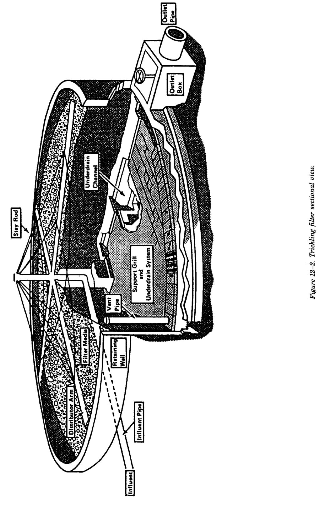
8 12-4. Secondary sedimentation tanks. The purpose of secondary sedimentation tanks is to allow the biological solids in the wastewater leaving the trickling filter to settle out. This produces an effluent for discharge, and the settled solids can be recirculated to the trickling filter to enhance its performance. Chapter 11 provides additional details on the design of secondary sedimentation systems. a. Design philosophy. The tanks will be designed for either the average daily flow rate or the daily flow equivalent to the peak 3-hour flow rate, whichever is greater. All of the appurtenant piping, channels, inlets, outlets and weirs will be designed to handle the peak flow rate. If there are no data for peak flow rates available, then a value of 3 times the average flow rate will be used. Two tanks, operating in parallel, will be used in all treatment plants with a design capacity greater than 0.1 million gallons per day. Each tank will be designed to treat 67 percent of the design flow. A single tank may be used in treatment plants with design capacity less than 0.1 million gallons per day but an equalization tank or holding basin must be provided to provide some settling capacity for those times when the secondary sedimentation requires maintenance. b. Design criteria. The sedimentation tanks should be designed for either the average flow rate or peak flow rate, whichever requires the largest surface area. The following table presents the design criteria for various size treatment plants: Other filter components. Table 12-4 gives a list of other components normally associated with trickling filters and for which design requirements are specified. Trickling filter design must include provisions for flooding the filter and the filter walls, and appurtenances must be able to structurally withstand the resulting hydrostatic pressure forces when the filter is flooded. In northern regions that are subject to extreme and/or prolonged freezing conditions, including high wind chill factors, design considerations must be given to providing filter dome covers or windbreaks. Figure 12-2 is a sectional view of a trickling filter. 12-8
9 Table Miscellaneous filter component design criteria. 12-9
10 12-10
Figure Trickling Filter
 19.2 Trickling Filter A trickling filter is a fixed film attached growth aerobic process for treatment of organic matter from the wastewater. The surface of the bed is covered with the biofilm and as the
An Introduction to Secondary Wastewater Treatment
 An Introduction to Secondary Wastewater Treatment Guyer Partners 44240 Clubhouse Drive El Macero, CA 95618 (530) 758-6637 jpguyer@pacbell.net J. Paul Guyer, P.E., R.A. Paul Guyer is a registered mechanical
ATTACHMENT 1 GENERAL FACILITY INFORMATION. BOD5 mg/l mg/l TSS mg/l mg/l NH3-N mg/l mg/l
 ATTACHMENT 1 GENERAL FACILITY INFORMATION 1. Facility Name: 2. Type of Facility: 3. Population Served: Present: Design: 4. Flow: Average Maximum Peak 5. Water Quality: Present Design Assumed Actual Source:
Module 20: Trickling Filters Answer Key
 Module 20: Trickling Filters Answer Key Calculation Capital City WWTF, which processes 2.0 MGD, is required to nitrify to meet the 2.0 mg/l ammonia discharge limit stated in their NPDES permit. A table
Biofilm Reactor Technology and Design
 Chapter 13 Biofilm Reactor Technology and Design 1.0 INTRODUCTION: BIOFILMS AND BIOFILM REACTORS IN MUNICIPAL WASTEWATER TREATMENT 13-5 1.1 Biofilm Reactor Compartments 13-8 1.2 Biofilm Processes, Structure,
ENVE 302 Environmental Engineering Unit Processes TRICKLING FILTERS ROTATING BILOGICAL CONTACTORS (RBC)
") ENVE 302 Environmental Engineering Unit Processes CHAPTER: 13 TRICKLING FILTERS ROTATING BILOGICAL CONTACTORS (RBC) Assist. Prof. Bilge Alpaslan Kocamemi Marmara University Department of Environmental
ENVE 302 Environmental Engineering Unit Processes CHAPTER: 13 TRICKLING FILTERS ROTATING BILOGICAL CONTACTORS (RBC) Assist. Prof. Bilge Alpaslan Kocamemi Marmara University Department of Environmental
SETTLING REVIEW CHECKLIST
 SETTLING REVIEW CHECKLIST Water Quality Wastewater Technical Review and Guidance FACILITY NAME CONSULTING ENGINEER DATE Water/Wastewater/#5.73, May 2001 SITE INSPECTION (DATE & INSPECTOR) PLANNING OR DESIGN
American Water College 2010
 Vocabulary Trickling Filters Biomass A mass or clump of organic material consisting of living organisms feeding on the wastes in wastewater, dead organisms and other debris. Colloids Very small, finely
CHAPTER 10 PRELIMINARY TREATMENT
 CHAPTER 10 PRELIMINARY TREATMENT TM 5-814-3/AFM 88-11, Volume III 10-1. General considerations. Preliminary treatment of wastewater includes screening, grinding, grit removal, flotation, equilization,
WASTEWATER TREATMENT PLANT MASTER PLAN 6. BUSINESS CASE EVALUATION OF ALTERNATIVES
 WASTEWATER TREATMENT PLANT MASTER PLAN 6. BUSINESS CASE EVALUATION OF ALTERNATIVES A range of potential ammonia limits were identified for alternatives evaluation, as discussed in Section 2.2.5. This chapter
Secondary Wastewater Treatment
 The Islamic University of Gaza Faculty of Engineering Civil Engineering Department Sanitary Engineering (ECIV 4325) Instructor: Dr. Abdelmajid Nassar Lect. W12-13 Secondary Wastewater Treatment Treatment
Palmer Wastewater Treatment Plant Environmental Impacts. A summary of the impacts of this treatment alternative are listed below:
 6.1.3 Environmental Impacts A summary of the impacts of this treatment alternative are listed below: 1. The Matanuska River will receive treated effluent as it currently does. 2. Effluent quality would
/ Marley MARPAK Modular Biomedia /
 / Marley MARPAK Modular Biomedia / The Marley MARPAK Difference SPX Cooling Technologies is a world leader in the design, manufacturing and construction of cooling products. The design and production of
Trickling Filters and Rotary Biological Contactors
 Trickling Filters and Rotary Biological Contactors CE - 370 1 Trickling Filters Definition: a biological process in which the microorganisms are attached to the filter media Trickling filters are composed
CEE 371 Water and Wastewater Systems
 Updated: 9 December 2009 CEE 371 Water and Wastewater ystems Print version Lecture #32 Wastewater Treatment: Biological Principles and Biological Filtration Reading: Chapter 11, pp.381-392 David Reckhow
IMPROVED BIO-TOWER TECHNOLOGY MUNICIPAL SEWAGE TREATMENT
 IMPROVED BIO-TOWER TECHNOLOGY FOR MUNICIPAL SEWAGE TREATMENT Regd. Office : Henabh Center, 1326, Shukrawar Peth, Off. Bajirao Road, PUNE : 411 002 (INDIA), Tel. : 24473299 (5 Lines) 24474696, (Voice Mail)
AERATED POND REVIEW CHECKLIST
 Water Quality AERATED POND REVIEW CHECKLIST Wastewater Technical Review and Guidance FACILITY NAME Water/Wastewater/#5.04, May 2001 DATE CONSULTING ENGINEER SITE INSPECTION (DATE & INSPECTOR) PLANNING
1/11/2016. Types and Characteristics of Microorganisms. Topic VI: Biological Treatment Processes. Learning Objectives:
 Topic VI: Biological Treatment Processes Learning Objectives: 1. Discuss microbiology and relate it to wastewater treatment. 2. Describe growth kinetics of pure bacterial culture with Monod expression
Physical water/wastewater treatment processes
 Physical water/wastewater treatment processes Tentative schedule (I) Week 1: Introduction Week 2: Overview of water/wastewater treatment processes Week 3: Major contaminants (Chemicals and pathogens) Week
Sanitary and Environmental Engineering I (4 th Year Civil)
") Sanitary and Environmental Engineering I (4 th Year Civil) Prepared by Dr.Khaled Zaher Assistant Professor, Public Works Engineering Department, Faculty of Engineering, Cairo University Wastewater Flow
Sanitary and Environmental Engineering I (4 th Year Civil) Prepared by Dr.Khaled Zaher Assistant Professor, Public Works Engineering Department, Faculty of Engineering, Cairo University Wastewater Flow
Effluent Conveyance. Paul Trotta, P.E., Ph.D. Justin Ramsey, P.E. Chad Cooper
 Effluent Conveyance Paul Trotta, P.E., Ph.D. Justin Ramsey, P.E. Chad Cooper University Curriculum Development for Decentralized Wastewater Management 1 NDWRCDP Disclaimer This work was supported by the
Fixed-Film Processes
 Onsite Wastewater Treatment Systems Technology Fact Sheet 2 Fixed-Film Processes Introduction Description Fixed-film systems (FFS) are biological treatment processes that employ a medium such as rock,
MARPAK modular biomedia WASTEWATER TREATMENT
 MARPAK modular biomedia WASTEWATER TREATMENT The Marley MARPAK Difference SPX Cooling Technologies is a world leader in the design, manufacturing and construction of evaporative cooling products. The design
FAYOUM CITY SEWAGE TREATMENT PLANT, DEVELOPMENT STAGES, CASE STUDY
 FAYOUM CITY SEWAGE TREATMENT PLANT, DEVELOPMENT STAGES, CASE STUDY Ahmed El-Zayat, Environmental Engineering Group, Egypt Emaill: ahmed_el_zayat@yahoo.com Introduction This case study focuses on three
Presenters: Rodrigo Pena-Lang, PE (D&B Engineers), Magdalena Gasior, PE (D&B Engineers) and Paul D. Smith, PE (NYCDEP)
, Magdalena Gasior, PE (D&B Engineers) and Paul D. Smith, PE (NYCDEP)") NYWEA-NEWEA Joint Conference June 7, 2016 Presenters: Rodrigo Pena-Lang, PE (D&B Engineers), Magdalena Gasior, PE (D&B Engineers) and Paul D. Smith, PE (NYCDEP) Overview Port Jervis WWTP History Division
NYWEA-NEWEA Joint Conference June 7, 2016 Presenters: Rodrigo Pena-Lang, PE (D&B Engineers), Magdalena Gasior, PE (D&B Engineers) and Paul D. Smith, PE (NYCDEP) Overview Port Jervis WWTP History Division
Chapter 9 Sanitary Sewers
 Chapter 9 Sanitary Sewers I:\AD\030\U30\U30009.docx 4-8-16 Section 9.1 Topic General Requirements Chapter 9 Sanitary Sewers Page 9-1 9.2 Plan Submittals 9-1 9.3 Determination of Flow 9-1 9.4 Facility Design
Contents General Information Abbreviations and Acronyms Chapter 1 Wastewater Treatment and the Development of Activated Sludge
 Contents Contents General Information Abbreviations and Acronyms... 6 Chapter 1 Wastewater Treatment and the Development of Activated Sludge... 8 The Importance of Wastewater Treatment... 8 The Scope of
SECTION-I. b) Write a short note on pumping of savage. 4
 Write a short note on pumping of savage. 4") UNIVERSITY OF PUNE [4364]-401 B. E. (Civil Engineering Semester I) Examination - 2013 ENVIRONMENTAL ENGINEERING-II (2008 Pattern) [Total No. of Questions :12] [Total No. of Printed Pages :4] [Time : 3
UNIVERSITY OF PUNE [4364]-401 B. E. (Civil Engineering Semester I) Examination - 2013 ENVIRONMENTAL ENGINEERING-II (2008 Pattern) [Total No. of Questions :12] [Total No. of Printed Pages :4] [Time : 3
CTB3365x Introduction to Water Treatment
 CTB3365x Introduction to Water Treatment W3b Trickling filters Jules van Lier Bacteria and other microorganisms have the ability to form biofilms on inert support media. Can we use these biofilm systems
Sag Pipe (depressed sewers, or Inverted siphons) Dr. Sataa A. Al-Bayati(10-11)
 Dr. Sataa A. Al-Bayati(10-11)") بسم هللا الرحمن الرحيم Sag Pipe (depressed sewers, or Inverted siphons) Dr. Sataa A. Al-Bayati(10-11) A sewer that drops below the hydraulic gradient to pass under an obstruction, such as a railroad cut,
بسم هللا الرحمن الرحيم Sag Pipe (depressed sewers, or Inverted siphons) Dr. Sataa A. Al-Bayati(10-11) A sewer that drops below the hydraulic gradient to pass under an obstruction, such as a railroad cut,
Wastewater Collection System
 WASTEWATER COLLECTION SYSTEM CE 370 1 Wastewater Collection System The function of the collection system is to collect the wastewater from residential, commercial, and industrial areas within the service
PRELIMINARY WASTEWATER CAPACITY STUDY
 PRELIMINARY WASTEWATER CAPACITY STUDY Tentative Tract Map No. 18955 CITY OF HESPERIA Prepared for: HESPERIA VENTURES I, LLC 10410 Roberts Road Calimesa, CA 92320 Tel (714) 785 2381 Mr. John Ohanian Prepared
SUPPLEMENTAL MECHANICAL CORRECTION SHEET FOR SEWAGE EJECTORS AND SUMP PUMPS 2011 LAPC
 SUPPLEMENTAL MECHANICAL CORRECTION SHEET FOR SEWAGE EJECTORS AND SUMP PUMPS 2011 LAPC This is intended to provide uniform application of the codes by the plan check staff and to help the public apply the
Wastewater Collection. (Sewer Alternatives)
") Wastewater Collection (Sewer Alternatives) Sewer Basics Collection and transport of wastewater from each home/building to the point where treatment occurs. Wastewater Characterization Solids Liquids Pipe
Wastewater Collection (Sewer Alternatives) Sewer Basics Collection and transport of wastewater from each home/building to the point where treatment occurs. Wastewater Characterization Solids Liquids Pipe
Assuming 100 gallons per capita per day, and 3 people per REU, design flows for the development are proposed to be:
 Andelina Farms Wastewater Treatment Plant Preliminary Basis of Design May 2018 Andelina Farms is a proposed Planned Unit Development in Saline Township located along US-12 just west of the City of Saline.
SECTION A-A. Blower Housing. Settling Zone Volume times daily flow. Treatment Zone. SaniTEE 818-B. Vent. Shutoff Valve.
 A Shutoff Valve Influent Distribution Box See note 11 Volume 0.5-1 times daily flow Mixing Pump Recirculation Pump Discharge SaniTEE 818-B Recirculation Pump Vent Control Panel Blower Housing A NOTES 1.
Onsite Wastewater Pretreatment Technologies
 Onsite Wastewater Pretreatment Technologies NDWRCDP Disclaimer This work was supported by the National Decentralized Water Resources Capacity Development Project (NDWRCDP) with funding provided by the
On-lot System Component Requirements
 On-lot System Component Requirements All system components used with an on-lot system employing an Eljen GSF System must meet either the requirements of Title 25, Chapter 73 or the Eljen GSF Listing. The
We Know Water. AnoxKaldnes. Moving Bed Biofilm Reactor (MBBR) Integrated Fixed-Film Activated Sludge (IFAS) and ANITA Mox Deammonification
 Integrated Fixed-Film Activated Sludge (IFAS) and ANITA Mox Deammonification") APPENDIX C.2 IFAS We Know Water AnoxKaldnes Moving Bed Biofilm Reactor (MBBR) Integrated Fixed-Film Activated Sludge (IFAS) and ANITA Mox Deammonification WATER TECHNOLOGIES AnoxKaldnes MBBR and Hybas
APPENDIX C.2 IFAS We Know Water AnoxKaldnes Moving Bed Biofilm Reactor (MBBR) Integrated Fixed-Film Activated Sludge (IFAS) and ANITA Mox Deammonification WATER TECHNOLOGIES AnoxKaldnes MBBR and Hybas
Appendix J Effluent Pump Station
 Appendix J Effluent Pump Station TECHNICAL MEMORANDUM Salmon Creek Treatment Plant Effluent Pump Station Hydraulics and Phasing Analysis for the Phase 5A Project Columbia River Outfall and Effluent Pipeline
Best Practice in Sewage and Effluent Treatment Technologies
 Best Practice in Sewage and Effluent Treatment Technologies Contents 1 Wastewater - Introduction 1 1.1 Earth s ecological system 1 1.1.1 Water effect on ecology 2 1.1.2 Wastewater generation 3 1.2 Wastewater
PERFORMANCE OF FLOATING HORIZONTAL AERATORS IN AERATED LAGOONS AND OXIDATION DITCHES
 PERFORMANCE OF FLOATING HORIZONTAL AERATORS IN AERATED LAGOONS AND OXIDATION DITCHES PRESENTED ON WEDNESDAY, APRIL 4, 2001 AT THE TEXAS WATER 2001 ANNUAL CONFERENCE LARRY W. MOORE CIVIL ENGINEERING DEPARTMENT
WASTEWATER TREATMENT (1)
") Wastewater Engineering (MSc program) WASTEWATER TREATMENT (1) Prepared by Dr.Khaled Zaher Assistant Professor, Public Works Engineering Department, Faculty of Engineering, Cairo University Wastewater Flow
Wastewater Engineering (MSc program) WASTEWATER TREATMENT (1) Prepared by Dr.Khaled Zaher Assistant Professor, Public Works Engineering Department, Faculty of Engineering, Cairo University Wastewater Flow
CEE 371 May 14, 2009 Final Exam
 CEE 371 May 14, 2009 Final Exam Closed Book, two sheets of notes allowed Please answer questions 3, 6 and 7. In addition, answer either question 1 or 2, and answer either question 4 or 5. The total potential
SECTION 2 - DESIGN STANDARDS FOR GRAVITY SANITARY SEWERS
 SECTION 2 - DESIGN STANDARDS FOR GRAVITY SANITARY SEWERS 2.1. General Requirements Sanitary sewers are to be provided solely for the removal of sanitary waste. Under no circumstances shall any roof drains,
3.9 times the average 3.8 times the average 3.6 times the average
 ARTICLE VI DESIGN OF SANITARY SEWERS M'RSMIN. VOL.281 JA 2 4 2001 IMAGE; Section 601 Determination of the Amount of Sewage for Sanitary Sewers A. MSD Design Standards for estimating sanitary sewage flow
Waste Water treatment
 The Islamic University of Gaza Faculty of Engineering Civil Engineering Department Environmental Engineering (ECIV 4324) Instructor: Dr. Abdelmajid Nassar Lect. 24-25 Waste Water treatment 1 Composition
Learning objectives. Upon successful completion of this lecture, the participants will be able to:
 Solomon Seyoum Learning objectives Upon successful completion of this lecture, the participants will be able to: Describe and perform the required step for designing sewer system networks Outline Design
LAKESIDE Water Purification Since Bulletin #1218 Revised June Spiravac Clarifier. Peripheral Feed Center Takeoff Suction Sludge Removal
 LAKESIDE Water Purification Since 98 Bulletin #8 Revised June 999 Peripheral Feed Center Takeoff Suction Sludge Removal Copyright Lakeside Equipment Corporation 999 The Spiraflo principle has been successfully
NORTH CAROLINA DEPARTMENT OF ENVIRONMENT AND NATURAL RESOURCES DIVISION OF ENVIRONMENTAL HEALTH ON-SITE WASTEWATER SECTION
 NORTH CAROLINA DEPARTMENT OF ENVIRONMENT AND NATURAL RESOURCES DIVISION OF ENVIRONMENTAL HEALTH ON-SITE WASTEWATER SECTION INNOVATIVE WASTEWATER SYSTEM APPROVAL, Attachment INNOVATIVE WASTEWATER SYSTEM
AALSO Summary of Formulas needed for Levels I, II and III.
 AALSO Summary of Formulas needed for Levels I, II and III. The information provided below is used in the math portion of the proficiency exams. Please take time to review and learn how to use these formulas
Commonwealth of Pennsylvania Department of Environmental Protection (DEP) Bureau of Water Standards and Facility Regulation Harrisburg, PA
 Bureau of Water Standards and Facility Regulation Harrisburg, PA") Commonwealth of Pennsylvania Department of Environmental Protection (DEP) Bureau of Water Standards and Facility Regulation Harrisburg, PA Issued to: Eljen Corporation 125 McKee Street East Hartford, CT
Commonwealth of Pennsylvania Department of Environmental Protection (DEP) Bureau of Water Standards and Facility Regulation Harrisburg, PA Issued to: Eljen Corporation 125 McKee Street East Hartford, CT
ENVIRONMENTAL ENGINEERING. Chemical Engineering department
 ENVIRONMENTAL ENGINEERING Chemical Engineering department 1- PRELIMINARY AND PRIMARY TREATMENT Screening is the first technique employed in primary treatment, which is the first step in the wastewater
A SIMPLE SOLUTION TO BIG SNAIL PROBLEMS - A CASE STUDY AT VSFCD S RYDER STREET WASTEWATER TREATMENT PLANT
 A SIMPLE SOLUTION TO BIG SNAIL PROBLEMS - A CASE STUDY AT VSFCD S RYDER STREET WASTEWATER TREATMENT PLANT Timothy R. Tekippe, P.E.,* Robert J. Hoffman, P.E.,* Ronald J. Matheson,** Barry Pomeroy** *Carollo
Pump Tank and Pretreatment Inspection & Troubleshooting. Sara Heger University of Minnesota
 Pump Tank and Pretreatment Inspection & Troubleshooting Sara Heger University of Minnesota sheger@umn.edu Evaluate Presence of Odor Odors are improper venting Check seals Lid Conduit Tank Access a. Access
Course: Wastewater Management
 Course: Wastewater Management Prof. M. M. Ghangrekar Questions 1 1. Describe advantages and disadvantages offered by the water carriage system. 2. What are the possible adverse effects when untreated or
City of Gardiner, Maine Wastewater Committee Meeting. CSO Storage Tank & Screening Evaluation
 City of Gardiner, Maine Wastewater Committee Meeting CSO Storage Tank & Screening Evaluation December 11, 2013 Introduction - Update on field work - Flow monitoring - Survey - GIS - Borings - Assessment
Water and Wastewater Engineering Dr. Ligy Philip Department of Civil Engineering Indian Institute of Technology, Madras
 Water and Wastewater Engineering Dr. Ligy Philip Department of Civil Engineering Indian Institute of Technology, Madras Attached Growth Aerobic Process: Trickling Filters and Rotating Biological contactors
Calculate the Costs of Piping System Elements
 Calculate the Costs of Piping System Elements by Ray Hardee, Engineered Software, Inc. Last month s column described the process of creating an energy cost balance sheet for a piping system (see Figure
COLD WEATHER NITRIFICATION OF LAGOON EFFLUENT USING A MOVING BED BIOFILM REACTOR (MBBR) TREATMENT PROCESS
 TREATMENT PROCESS") ABSTRACT COLD WEATHER NITRIFICATION OF LAGOON EFFLUENT USING A MOVING BED BIOFILM REACTOR (MBBR) TREATMENT PROCESS Mr. Flemming G. Wessman 1 and Mr. Chandler H. Johnson 1 AnoxKaldnes, Inc., 58 Weybosset
ABSTRACT COLD WEATHER NITRIFICATION OF LAGOON EFFLUENT USING A MOVING BED BIOFILM REACTOR (MBBR) TREATMENT PROCESS Mr. Flemming G. Wessman 1 and Mr. Chandler H. Johnson 1 AnoxKaldnes, Inc., 58 Weybosset
DRIP EMITTER SYSTEM STUDY GUIDE
 DRIP EMITTER SYSTEM STUDY GUIDE Minimum Criteria for Pressurized Subsurface Absorption Fields Utilizing Emitters. Subsurface systems utilizing emitters may be used in lieu of conventional or other alternative
ISAM SBR with Blower Assisted Jet Aeration Design Calculations For Lyons, CO WWTP Upgrade
 ISAM SBR with Blower Assisted Jet Aeration Design Calculations For Lyons, CO WWTP Upgrade May. 28, 2013 A. Site Conditions 1. Site elevation = 5,322 ft MSL 2. Average barometric pressure = 12.07 psia 3.
SECTION A-A. Control Panel
 SaniTEE 818-B Blower Housing Settling Zone 1050 Gallon MIN 4500 Gallons Control [4000 L MIN] [17000L] Panel 183 MX 72 MX Height of Effluent Line 1. Blower piping to BioBarrier MBR may not exceed 40 FT
Appendix B-1. Design Calculations for Sewage Treatment Plant
 APPENDIX B SEWERAGE FACILITIES Appendix B-1 Design Calculations for Sewage Treatment Plant Appendix. B.1 CAPACITY CALCULATION OF SEWAGE TREATMENT PLANT 1 BASIC CONDITIONS 1.1 BASIC S (1) Name : Astana
2. DEFINITIONS. American Association of State Highway and Transportation Officials.
 2. DEFINITIONS 2.010 Definitions [See Amendment 2] In addition to words and terms that may be defined elsewhere in this manual, the following words and terms shall have the meanings defined below: AASHTO:
Chapter 6 STEP System Force Main Velocity Evaluation
 Chapter 6 STEP System Force Main Velocity Evaluation \\7348101\TOC.doc CHAPTER 6 STEP System Force Main Velocity Evaluation 6.1 INTRODUCTION The City s existing STEP (septic tank effluent pump) pumps currently
XII. APPENDIX B DECENTRALIZED MANAGED WASTEWATER SYSTEMS (DMWS) IN DETAIL
 IN DETAIL") XII. APPENDIX B DECENTRALIZED MANAGED WASTEWATER SYSTEMS (DMWS) IN DETAIL General Description Decentralized wastewater systems (DWS) cover a wide variety of collection, treatment, and disposal systems.
XII. APPENDIX B DECENTRALIZED MANAGED WASTEWATER SYSTEMS (DMWS) IN DETAIL General Description Decentralized wastewater systems (DWS) cover a wide variety of collection, treatment, and disposal systems.
Oregon Operators Conference Operator Math Workshop Module II
 Oregon Operators Conference Operator Math Workshop Module II Lance Mason, Senior Operations Specialist August 16, 2018 Conversion Math Brief Review From Module I Conversions to Remember 8.34 lbs. / gallon
Activated Sludge Process Control:
 2015 Pacific Water Conference Activated Sludge Process Control: What s Important and How It s Easily Implemented February 2015 Presentation takeaways 1. MCRT/SRT is the only way to control the activated
Module 19 : Aerobic Secondary Treatment Of Wastewater. Lecture 24 : Aerobic Secondary Treatment Of Wastewater
 1 P age Module 19 : Aerobic Secondary Treatment Of Wastewater Lecture 24 : Aerobic Secondary Treatment Of Wastewater 2 P age 19.1 Activated Sludge Process Conventional biological treatment of wastewater
CHAPTER 4 DESIGN CRITERIA
 CHAPTER 4 DESIGN CRITERIA 4.1 INTRODUCTION This chapter summarizes the basic design criteria necessary to develop options and sizing estimates for the components of centralized wastewater collection systems.
INYO COUNTY ENVIRONMENTAL HEALTH SERVICES RESIDENTIAL ONSITE SEWAGE TREATMENT AND DISPOSAL GUIDE
 INYO COUNTY ENVIRONMENTAL HEALTH SERVICES RESIDENTIAL ONSITE SEWAGE TREATMENT AND DISPOSAL GUIDE I. SCOPE This guide has been prepared to inform the residential property owner of the permitting process
1. Overview 2 2. Definitions 2 3. Laboratory Testing Criteria 2. A. Laboratory Qualifications 2. B. Analysis of TSS Samples 2. C.
 New Jersey Department of Environmental Protection Laboratory Protocol to Assess Total Suspended Solids Removal by a Hydrodynamic Sedimentation Manufactured Treatment Device January 25, 2013 Contents 1.
TRICKLING FILTERS by Dr. Moazzam Ali Khan
 TRICKLING FILTERS by Dr. Moazzam Ali Khan Trickling filters Trickling filter is an attached growth process i.e. process in which microorganisms responsible for treatment are attached to an inert packing
APPENDIX G HYDRAULIC GRADE LINE
 Storm Drainage 13-G-1 APPENDIX G HYDRAULIC GRADE LINE 1.0 Introduction The hydraulic grade line is used to aid the designer in determining the acceptability of a proposed or evaluation of an existing storm
PRIVATE STORM DRAINAGE FACILITIES REQUIREMENTS
 PRIVATE STORM DRAINAGE FACILITIES REQUIREMENTS 39 AUGUST 2005 TABLE OF CONTENTS PRIVATE STORM DRAINAGE FACILITIES REQUIREMENTS PAGE SECTION 1 DESIGN CRITERIA 41 SECTION 2 SUBMITTAL 44 SECTION 3 STRUCTURES
Contact the Jurisdictional Engineer for materials allowed by each jurisdiction.
 Design Manual Chapter 3 - Sanitary Sewers 3C - Facility Design 3C-1 Facility Design A. Capacity of Pipe Pipe sizes 15 inches and smaller should carry the peak flow at a depth of no more than 0.67 of the
Aeration Blower Requirements. Tom Jenkins 06/15/2016
 Aeration Blower Requirements Tom Jenkins 06/15/2016 Aeration blowers receive a lot of attention from design engineers, suppliers, and end users. That is understandable since blowers account for more than
3.0 DESIGN CRITERIA FOR SANITARY SEWER FACILITIES
 3.0 DESIGN CRITERIA FOR SANITARY SEWER FACILITIES All sanitary sewers shall be designed in accordance with these Design Standards, LBWD Rules and Regulations, and to accepted engineering principles. In
Lynn Township Sewer Authority. Corrective Action Plan. March 2007
 Lynn Township Sewer Authority Corrective Action Plan March 2007 4130.00 Prepared By: ARRO Consulting, Inc. 400 Washington Street, Suite 602 Reading, Pennsylvania 19610 610 374 5285 Corrective Action Plan
Wetlands Application. Constructed Wetlands
 Constructed Wetlands A constructed wetland system treats wastewater by filtration, settling, and bacterial decomposition in a lined marsh. Constructed wetland systems have been used nationally and internationally
Commonwealth of Pennsylvania Department of Environmental Protection (DEP) Bureau of Point and Non-Point Source Management Harrisburg, PA
 Bureau of Point and Non-Point Source Management Harrisburg, PA") Commonwealth of Pennsylvania Department of Environmental Protection (DEP) Bureau of Point and Non-Point Source Management Harrisburg, PA Issued to: Technology: Premier Tech Aqua 1160, rue Levis, bureau
Commonwealth of Pennsylvania Department of Environmental Protection (DEP) Bureau of Point and Non-Point Source Management Harrisburg, PA Issued to: Technology: Premier Tech Aqua 1160, rue Levis, bureau
STORM DRAINAGE DESIGN MANUAL
 Appendix I STORM DRAINAGE DESIGN MANUAL by: SUNGATE DESIGN GROUP, P.A. GEN ERAL DESIGN STAN DARDS AN D POLICIES 1. STREET AND LOCAL DRAINAGE Discharge estimates for specified design storms shall be calculated
INTERNATIONAL ASSOCIATION OF PLUMBING AND MECHANICAL OFFICIALS IAPMO GUIDE CRITERIA FOR
 INTERNATIONAL ASSOCIATION OF PLUMBING AND MECHANICAL OFFICIALS IAPMO GUIDE CRITERIA FOR WASTEWATER INTERCEPTOR SYSTEM (WIS) FOR AN INTERACTIVE MECHANICAL WASTEWATER INTERCEPTOR IGC 245-2007a 1. PURPOSE
2015 HDR, Inc., all rights reserved.
 2015 HDR, Inc., all rights reserved. Hastings Utilities Water Pollution Control Facility Improvements Brian Bakke, HDR ASCE Environmental Conference 4/6/2017 Review Existing Facilities Need for the Project
Walker Process Equipment
 Walker Process Equipment Equipment For The Water & Wastewater Industry Aurora, IL Sludge Collection General Bulletin Sludge Digestion Biological Process Grit Removal Grease & Skimmings Water Treatment
Complex Sewage Disposal Course 2017
 Complex Sewage Disposal Course 2017 Updates to the Technical Guidance Manual This information is based on the most recent version of the TGM. Updates from previous versions can be found on DEQ s website
CHAPTER 5. COLLECTION SYSTEM ALTERNATIVES
 CHAPTER 5. COLLECTION SYSTEM ALTERNATIVES This chapter evaluates alternative wastewater collection system technologies. Each technology is described along with the relative advantages and drawbacks for
Packaged Wastewater Treatment Systems for Individual Homes and Small Communities. Mark Gross Orenco Systems, Inc. Sutherlin, OR USA.
 Packaged Wastewater Treatment Systems for Individual Homes and Small Communities Mark Gross Orenco Systems, Inc. Sutherlin, OR USA Abstract Packaged or pre-engineered wastewater treatment systems are required
MATHEMATICS FOR WATER OPERATORS
 MATHEMATICS FOR WATER OPERATORS Mathematics The understanding of the mathematics of water hydraulics (flows, pressures, volumes, horsepower, velocities) and water treatment (detention time, chemical dosage)
CHAPTER 17: STORM SEWER STANDARDS Introduction Administration Standards 17.1
 CHAPTER 17: STORM SEWER STANDARDS 17.00 Introduction 17.01 Administration 17.02 Standards 17.1 17.00 INTRODUCTION The purpose of this chapter is to provide guidance for the design and construction of storm
APPENDIX A LOW PRESSURE DOSED SAND FILTERS
 3701-29-13 1 I. Introduction APPENDIX A LOW PRESSURE DOSED SAND FILTERS Low pressure dosed sand filters (LPDSF) are aerobic, fixed-film bioreactors that are capable of treating septic tank effluent (or
Waste Water Treatment Equipment
 APEC PUMP ENTERPRISE CORP. Waste Water Treatment Equipment APEC Separator APEC Separator Compared with a sedimentation basin, the APEC separator offers a 90% saving in terms of surface area. This means
City of Elk River Wastewater Treatment Facility Improvements. Achieving Wastewater Treatment Goals
 City of Elk River Wastewater Treatment Facility Improvements Achieving Wastewater Treatment Goals By Tejpal Bala, P.E. Bolton & Menk, Inc. The City of Elk River received a new NPDES permit and the existing
Session 2 Pump Selection. Mark Markham, P.E. Gresham, Smith and Partners September 14, 2017
 Session 2 Pump Selection Mark Markham, P.E. Gresham, Smith and Partners September 14, 2017 Quick Refresh System Curves graphically show the relationship between flow rates and associated total dynamic
Facilities Development Manual
 State of Wisconsin Department of Transportation Facilities Development Manual ORIGINATOR Director, Bureau of Highway Development PROCEDURE 13-25-35 CHAPTER 13 Drainage SECTION 25 Storm Sewer Design SUBJECT
- 1 - Retrofitting IFAS Systems In Existing Activated Sludge Plants. by Glenn Thesing
 - 1 - Retrofitting IFAS Systems In Existing Activated Sludge Plants by Glenn Thesing Through retrofitting IFAS systems, communities can upgrade and expand wastewater treatment without the expense and complication
4.28 Underground Detention
 4.28 Underground Detention Detention Structural Stormwater Control Description: Detention storage located in underground tanks or vaults designed to provide water quantity control through detention and/or
UPGRADING GAZA WASTEWATER TREATMENT PLANT. Gaza City is populated with 550,000 inhabitants and it forms 45% of the Gaza strip population.
 Gaza City Gaza City is populated with 550,000 inhabitants and it forms 45% of the Gaza strip population. Gaza City has the oldest wastewater system in Gaza Strip; it consists of some of 280 kilometers
Compact Waste Water Treatment MBR /MBBR Technology
 Compact Waste Water Treatment MBR /MBBR Technology 1 Minimal Operation and Maintenance Costs and use of Chemicals 2 Recycle and Reuse water for Irrigation and Recreation 3 Save Water, Energy, Money and