KENT BREEZE WIND FARMS
|
|
|
- Angelica Fitzgerald
- 6 years ago
- Views:
Transcription
1 Kent Breeze Corporation MacLeod Windmill Project Inc. KENT BREEZE WIND FARMS Construction Plan Report MAY 2010
2 IBI GROUP CONSTRUCTION PLAN REPORT TABLE OF CONTENTS 1. INTRODUCTION PURPOSE PRE-CONSTRUCTION ACTIVITIES CONSTRUCTION AND INSTALLATION ACTIVITIES ENVIRONMENTAL EFFECTS, MITIGATION MEASURES, AND MONITORING Appendix 1 Conceptual Site Plans Appendix 2 Construction Materials and Equipment Details Appendix 3 Technical Memos (Water Resources) May 2010 Page i.

3 IBI GROUP CONSTRUCTION PLAN REPORT Kent Breeze Corporation MacLeod Windmill Project Inc. KENT BREEZE WIND FARMS 1. INTRODUCTION The purpose of this management plan is to outline the methodology to be used by Kent Breeze Corporation & MacLeod Windmill Project in implementing construction activities during the construction phase of the Kent Breeze Wind Farms projection in the Municipality of Chatham-Kent. The report fulfills the requirement of Item 2 in Table 1 of Ontario Regulation 359/09. The proponents are proposing to construct two 4-turbine wind farms at the following locations: Project 1 Part Lots 8-11, Concession 1, in the geographic Township of Camden, in the Municipality of Chatham-Kent, on the south side of Smoke Line, east of Huffs Side Road; and Project 2 Part Lots 4-6, Concession 1 & 2, in the geographic Township of Camden, in the Municipality of Chatham-Kent, on the north and south side of Smoke Line, west of Huffs Side Road. The original owners of the proponent companies are the owners of all the lands and are involved in the day-to-day farming of the subject lands, and as such have made great efforts to establish good relations with the local community and plan to be a long-term member of the community. Suncor, the new owner of the proponent companies, continues to work with both the original developers and the community to foster positive working relationships. During construction, the company s emphasis will always be on control and mitigation of wind farm effects on the local community and the environment. The goal of the proponents during the construction of the wind farm projects will be: May 2010
4 IBI GROUP CONSTRUCTION PLAN REPORT Kent Breeze Corporation MacLeod Windmill Project Inc. KENT BREEZE WIND FARMS Safe work performance; On-schedule facility completion; Quality assurance (QA); Municipal cooperation; and Excellent community relations. 2. PURPOSE This document will provide general information to neighbours and the general public, municipal staff and the Provincial approval authority regarding the wind farm projects as well as outline implementation procedures and protocols. This will facilitate understanding of the construction of the wind farm. 2.1 Scope of the Construction Plan The Construction Plan includes the following specific areas: Construction Activities This section addresses the pre-construction studies, construction surveys, project management, and all aspects of construction of the project to be completed before the operational stage of the projects is reached. Construction Timeframe This section addresses the expected timeframe from the commencement of construction to the point at which the project begins to operate. Environmental Impacts of Construction Activities and Mitigation Measures This portion of the Construction Plan addresses any expected negative environmental impacts as a result of construction activities based on background research. The section also outlines the commitments by the owners of the wind farms to mitigate any negative environmental impacts. May 2010 Page 2
5 IBI GROUP CONSTRUCTION PLAN REPORT Kent Breeze Corporation MacLeod Windmill Project Inc. KENT BREEZE WIND FARMS 3. PRE-CONSTRUCTION ACTIVITIES 3.1 Pre-Construction Surveys CONSTRUCTION SURVEYS Site surveys will be carried out to accurately record the exact locations and position of the wind turbines, the access road routes, and various terminal points and interfaces of the services required, in conformance with the site plans provided in Tab 4 of this application, the Design and Operations Report. Prior to proceeding with construction, the survey will clearly identify, for the construction crews: Access roads, cable routing; Wind turbine locations; Limits of the construction service area and temporary storage area; Electrical distribution line connections and arrangement; and The proximity of overhead lines, natural gas, water, communication, power supply and drainage point connections as necessary. The survey will be undertaken by an Ontario Land Surveyor who will define, on plan, the boundaries of the facilities related to the legal property survey and UTM coordinates, NAD83, for registration of the plan after construction is complete. Levels will be taken as necessary to fully define the site profile and will be used as the vertical and horizontal control points for the project ELECTRICAL WORK The following electrical work will be undertaken to finalize the detailed electrical design of the projects: Short Circuit Study to evaluate and determine the peak duty and maximum break duty fault currents on all of the wind turbines and the interconnecting switchgear of the grid systems. Electrical System Coordination Study to fully specify power fuse ratings, protective relay characteristics and settings, ratios and characteristics; Grounding System Study - utilizing information on soil resistivity that has been made available through on-site testing. It is noted that, because the wind turbine generating equipment produces electricity at the distribution system voltage where the project interconnects (27.6kV), no substation transformers are required for the project. Instead of a substation, electrical lines will collect at a switching station complete with a metering device and various May 2010 Page 3
6 IBI GROUP CONSTRUCTION PLAN REPORT Kent Breeze Corporation MacLeod Windmill Project Inc. KENT BREEZE WIND FARMS protection equipment where it will then connect to the Hydro One 27.6kV distribution system. 3.2 Site Supervision The pre-construction activities will be managed by lead discipline engineers reporting to a Project Manager. Detailed engineering packages will be provided for the procurement of engineered equipment from vendors and third party suppliers. Detailed engineering drawings and material takeoff lists will be provided for procuring bulk electrical materials and construction of the balance of plant. The Project Manager will have overall responsibility for managing this phase of the project. Senior discipline engineers and the project manager will review and approve each of the vendors' packages, drawings, specifications and designs to ensure that the design of the project will meet the intended duty and will comply with specified requirements of the Owners. 3.3 Project Management ROLE The Owner s Project Manager will be responsible for the successful completion of the wind farm projects. The Project Manager will be supported on the Project by off-site design, procurement, project administration, planning/scheduling, construction management and supervision and other personnel assigned from affiliated companies, as required, to manage subcontractors and to selfperform work required to complete the Project SITE CONSTRUCTION The Project Manager, or delegated team member, will monitor and review all aspects of the construction of the project to ensure that the work is undertaken safely in accordance with the requirements of the drawings and specifications and in accordance to the project programme. The Project Manager will be responsible for the entire projects site activities until the construction phase of the projects close out. The Project Manager will be assisted and supported at various times throughout the construction phase by construction superintendents; civil and electrical personnel; commissioning and quality control; and/or health and safety professionals SITE MANAGEMENT RESPONSIBILITIES The Project Manager and the team will: Maintain good safety and health programs and practices as well as good environment control programs as part of all work activities; May 2010 Page 4
7 IBI GROUP CONSTRUCTION PLAN REPORT Kent Breeze Corporation MacLeod Windmill Project Inc. KENT BREEZE WIND FARMS Execute site construction, installation and testing of equipment to a high standard of quality; Act as an interface with operational staff, the subcontractors, third party inspectors (TPI) and other organizations involved with the Project; Manage any environmental and safety issues during construction and commissioning; Assist the Commissioning Engineer and their team in conducting site tests, including pre-commissioning, plant start-up, commissioning and supervise the TPI as required; Organize and attend regular site co-ordination meetings, progress meetings and prepare minutes of meetings; Maintain on-site, complete and proper records of the progress of the Project; Maintain accounts and records of the cost of the works; Maintenance of correct as-built drawings reflecting all changes and modifications; Training of operations and maintenance personnel; and Construction completion, testing and commissioning of all balance of plant items SUBCONTRACT MANAGEMENT Subcontract control will be conducted to ensure that any subcontractors carry out their work at the site in accordance with the Project safety and quality requirements and complete their work in accordance with the Project schedule. Any subcontractors will be controlled, with emphasis on safety; control of technical information; fulfilling reporting requirements; inspection and testing of construction material; and non-conformance and quality control. 4. CONSTRUCTION AND INSTALLATION ACTIVITIES 4.1 Materials Construction of the project will involve the materials outlined in the attached Appendix 2 (Materials Description). Heavy machinery, metal re-bar and wiring will be stored temporarily at the construction service area and temporary storage area (Appendix 1). Aggregate for the access roads and turbine staging areas will be delivered on-site as required. Upon completion of the roads and underground cabling, concrete for the turbine foundations will be delivered as required. Following curing of the concrete, turbines will be delivered and temporarily laid down adjacent to foundation areas. It is anticipated that the temporary turbine lay down areas will not last longer than 4-5 days as installation of an individual turbine can be completed within this approximate timeframe. May 2010 Page 5
8 IBI GROUP CONSTRUCTION PLAN REPORT Kent Breeze Corporation MacLeod Windmill Project Inc. KENT BREEZE WIND FARMS TRANSPORTATION TO AND FROM SITE The following chart outlines the detailed size, type and approximate number of trucks used to construct the project. It is estimated that approximately 3882 trips will be required through this process. Task Description Number of loads Mobilization and Offices Office and Storage Set up. 24 Approximately 4 loads for each 6 contractors Large Equipment Deliveries 2 Excavator 2 floating 4 2 Loader 2 floating 4 1 Grader 2 floating Ton Crane 2 floating Ton Crane 2 floating Ton Crane 2 floating 112 Access Road Materials Soil Excavation and Spread 1/2 525 quantity - 15,652 m³ granular A & B 850 Crane pad and erection Area Excavation 335 Backfill 270 Foundation Excavation 750 Engineering Fill 35 Mud Slab 7m³ per truck 55 Concrete footing 640 Concrete Pumps 24 Formwork 8 floating total 16 Steel Reinforcement 2 loads per 16 footing Anchor bolts and adaptor 8 Wind Turbines 16 truck loads for each tower 128 Cable and Trenching Cable reel delivery 20 Trenching equipment (2 sets) 4 transport Directional drilling equipment 4 transport Electrical Misc Major Equipment Deliveries 6 HONI line work deliveries 2 General Delivery Not Assume 2 delivery per week for the 32 Elsewhere Listed construction duration Total loads 3882 May 2010 Page 6
.")

9 IBI GROUP CONSTRUCTION PLAN REPORT Kent Breeze Corporation MacLeod Windmill Project Inc. KENT BREEZE WIND FARMS 4.2 Construction Equipment Construction of the project will involve the machinery outlined in the attached Appendix 2 (Construction Equipment). Such machinery will involve noise and dust emissions to within norms established for the construction industry in Ontario. Movement of earth and travel on turbine access roads will generate small amounts of dust which will fall on the project area. Water sprayers for the purposes of dust control are planned for public and turbine access roads as required by the municipality. Fuels (diesel and gasoline), lubricants (motor oils, hydraulic oils), and coolants (glycol blends) are used in the construction equipment; typical refuelling practice for mobile equipment is as follows: re-fuelling for smaller vehicles will take place at the construction service area (Appendix 1) that include a 500 gallon (double wall, vacuum) fuel tank, complete with fuel pump and safeties such as excess flow valves, and level limit controls for larger vehicles and cranes that cannot come to the construction service area, fuel is taken to them in fuel trucks; spill kits are available at the construction service area and within fuel trucks. Equipment is transported to and from the project area on flatbed trailers (referred to as "floated") between each wind turbine site, as well as on/off site where it is not permitted for the equipment to travel on public roads. In general, machines with "tracks" have to be floated (tracked cranes, front end loader) over public roads. 4.3 Wind Turbines STORAGE The majority of the project components will be temporarily stored at a central location identified in Appendix 1 (Temporary Storage Area). Wind turbines may be stored in this location, or, if delivery schedules permit, stored adjacent to the individual permanent erection locations FOUNDATIONS Wind turbine foundation areas will be excavated by tracked excavators to a depth of 2.5 meters (m). The projects will employ the use of piled foundations (see picture) due to local soil conditions which include a flat, soft, thick upper strata. The excavation compromises May 2010 Page 7

10 IBI GROUP CONSTRUCTION PLAN REPORT Kent Breeze Corporation MacLeod Windmill Project Inc. KENT BREEZE WIND FARMS the existing drainage tiles within the field resulting in some collection of surface water after a rain event. As a result small quantities of surface water may be required to be pumped from the excavation. Due to the shallow depth of the turbine bases (2.5m), the depth of the surrounding water table (approximately 5 metres) and the permeability of the soils, groundwater is not expected to enter the excavation (see Dewatering Memorandum - Appendix 3). Water collected in the foundation would be limited to surface water run-off during a rain event, thus dewatering activities would be periodic with precipitation events. Dewatering methods will employ a silt bag on the end of the pump discharge and use a sump as a suction point to pick up less saturated soil. Given the small amount of dewatering required, the outlets for any dewatering activities will be located adjacent to foundation areas and directed away from crops to avoid crop damage TURBINE ERECTION Wind turbine erection will be carried out using a crawler crane or truck mounted crane across identified access roads on privately owned lands. All movement of heavy machinery is conducted by engineered lifts. A crane movement plan will be expedited with the objective of minimizing impacts to public rights-of-way and public traffic. Turbines will be installed as per specifications provided by GE Energy. Wind turbine erection will occur when conditions allow for safe assembly conditions including wind speed and meteorological conditions. Wind speeds on-site will be measured at ½ hour intervals using a wind anemometer located on the top of the main crane. 4.4 Electrical Infrastructure These projects are distribution level projects and do not require the construction of any electrical transformers or transmission lines and as a result will contain no noise generating equipment. Two self-contained electrical switching stations (see picture) will be delivered on flatbed trailers and mounted on concrete pads at the identified locations. Underground cabling will connect to the switching stations at these locations and be connected directly to the existing Hydro One Networks 27.6kv lines overhead. May 2010 Page 8
11 IBI GROUP CONSTRUCTION PLAN REPORT Kent Breeze Corporation MacLeod Windmill Project Inc. KENT BREEZE WIND FARMS 4.5 Timing OBJECTIVE The development of an achievable and comprehensive schedule is essential to the success of the Project. A project schedule will be updated, based on approval of the REA application, which will form the basis of progress monitoring and act as principal indicator toward overall completion of the Project. The subcontractor programmes will be reviewed to ensure that they accurately reflect the sequence and timing of Project activities. If any anomalies are identified, the Project Manager will discuss these with the subcontractors to ensure that the detailed schedule is agreed to and is acceptable to all parties TIMELINE It is expected that project construction will take approximately six (6) months to complete. Construction of the project will begin as soon as building permits are granted by the Municipality of Chatham-Kent. Timing of activities will be as follows: Mobilization and office setup: Large equipment deliveries: Access road and crane pad / erection area construction: Foundations: Wind Turbines Cable and Trenching Approximate timing of construction phase: 1-2 weeks 1-2 weeks 4-8 weeks 6-12 weeks 2-4 weeks 2-4 weeks weeks Hours of operation for the above-noted activities will range from 8-12 hours a day depending on seasonal limitations and project deadlines. Construction activities will generally not occur outside the hours of 7am to 7pm. However, some construction activities may happen outside of this timeframe for items such as concrete finishing, late deliveries, critical lifts (may best be done later in the evening when winds reduce), and bolt ups once tower sections are put in place, which need to be secured before releasing the crane. These after-hours activities will not produce noise exceeding the municipal guidelines. 4.6 Temporary Uses of Land A construction service area and temporary storage area is identified on the conceptual plan being within and adjacent to the existing machine shed located on-site (Appendix 1). The approximate May 2010 Page 9
12 IBI GROUP CONSTRUCTION PLAN REPORT Kent Breeze Corporation MacLeod Windmill Project Inc. KENT BREEZE WIND FARMS outdoor temporary storage area will be 0.75 hectares in size. These lands are currently used for storage and field crop agricultural purposes and will be used for such purposes after the completion of the construction phase of the project in accordance with the above-noted timing of this phase of the project. 4.7 Excavation Materials All areas of disturbance due to construction of project components will be remediated for agricultural purposes. All topsoil excavated will be used elsewhere on-site for agricultural improvements where possible. Approximately half of the fill excavated for turbine foundations will be required to be trucked off-site. Such off-site materials will be clean and offered to surrounding landowners or taken to area contractors for future construction purposes. Such activities would involve approximately 5000m³ of clean fill and 150 vehicle trips. 4.8 Traffic Management The purpose of this section is to identify the safety measures, transport routes, monitoring and rehabilitation of municipal roads as needed over the duration of the project construction. The intent will be to maintain safe use of the roadways and minimize interference with the existing farm and passenger traffic around the wind farm sites PRE-CONSTRUCTION The Project Manager will meet with the municipality to identify the location of the temporary laydown area, the expected use of abutting roads, any road improvements or changes needed for access points or drain crossings in accordance with established municipal criteria. The Project Manager will identify the expected number of days of construction and hours of construction. It is expected the construction process will take six months. The Project Manager will advise the municipality of any unexpected changes to transport routes or timing due to delays. The Project Manager will work with the Municipality to determine best routes and timing related to school bus routes. The Project Manager and the municipal roads superintendent will inspect the proposed access routes to the construction sites to confirm the road conditions, sight lines, signage locations, drain crossings, and need for possible road improvements. This inspection will form the base line for future road rehabilitation as required. The Project Manager and municipality will determine a reasonable deposit in the form of a letter of credit or parental company guarantee to ensure rehabilitation of any road damage. May 2010 Page 10
13 IBI GROUP CONSTRUCTION PLAN REPORT Kent Breeze Corporation MacLeod Windmill Project Inc. KENT BREEZE WIND FARMS CONSTRUCTION The Project Manager will manage traffic in accordance with all Provincial and municipal laws in the applicable jurisdiction. The Project Manager will ensure that the appropriate signage is posted at the entrance and exit to the construction site, warning of the activity. The Project Manager will provide the necessary personnel to ensure safe ingress, egress, and traffic flow, to and through the project area as needed. The site will ensure safe turning movements to and from the site to avoid the need to back onto public roads. During construction all signage, signalling and related controls will be undertaken in accordance with the Manual of Uniform Traffic Control Devices, Ministry of Transportation Division 5, Temporary Conditions, April, The Project Manager will ensure the road is maintained and cleaned as needed in accordance with municipal standards. On a weekly basis, the Project Manager will ensure that no construction debris or mud from the site is left on the public roadway. The Project Manager will report any damage resulting from construction activity to the municipality POST-CONSTRUCTION Once construction of the projects is completed, the Project Manager will undertake an inspection of public roads used during construction with municipal staff to identify any required maintenance or damage. The results of the inspection will be documented. Where road damage is identified, the Project Manager will obtain estimates to repair the road to the pre-construction condition. The Project Manager will also restore any temporary site access points and remove any temporary road improvements related to the project. The municipality will return the deposit upon satisfactory inspection of the public roads and any repair work within three months of the end of construction. May 2010 Page 11
14 IBI GROUP CONSTRUCTION PLAN REPORT Kent Breeze Corporation MacLeod Windmill Project Inc. KENT BREEZE WIND FARMS 5. ENVIRONMENTAL EFFECTS, MITIGATION MEASURES, AND MONITORING This section gives detailed descriptions of the potential negative environmental impact that may be encountered during the construction phase, in or within 300 metres of the project area. Following each description are details of how the proponents will address any negative effects through mitigation and impact management measures. Next, a summarization of the expected net effect will be outlined based on any mitigation and impact management measures. Such net effects will be described on the following basis: Minimal potential negative effects may be encountered during construction phase, but is otherwise not encountered during life of project; Low potential negative effects may result in small deviations to the baseline data, but further commitments are not normally required; Medium potential negative effects may result in significant but stable deviations to the baseline data, and further commitments through research, monitoring, should be considered; High potential negative effects could create unsustainable impacts and are considered a concern. Further commitments should be considered to reduce effects. Finally, each subsection will conclude with a discussion of future commitments where necessary based on level of net effects. 5.1 Potential Negative Effects Surface and Groundwater IMPACT Surface water During the construction period of the wind farms, a potential exists for negative impacts to surface water features in the project area as a result of soil runoff and/or erosion, particularly where crossing of municipal drains is required during construction of access roads and underground cabling. The only surface water on site is in the form of drainage ditches adjacent to roads Groundwater During the construction period of the wind farms, a potential would exist for negative impacts to groundwater quality primarily as a result of turbine base construction. May 2010 Page 12
15 IBI GROUP CONSTRUCTION PLAN REPORT Kent Breeze Corporation MacLeod Windmill Project Inc. KENT BREEZE WIND FARMS Accidental Spills During the construction period of the wind farms, a potential would exist for the accidental spilling of oil/fuel related to construction machinery and generator equipment MITIGATION AND IMPACT MANAGEMENT MEASURES Surface water The proponents will utilize a combination of best management practices (BMP s); DFO supervision (through the LTVCA as the acting DFO agents); and in the case of the Shaw-Ferguson Drain crossing, a permit issued by the Saint Clair River Conservation Authority (SCRCA) in co-operation with the Department of Fisheries and Oceans (DFO). The DFO will require construction in accordance with their Operational Statement for High Pressure Directional Drilling and Operational Statement for Culvert Maintenance. The list of BMP s is included in Appendix 3 to this report Groundwater The proponents will utilize best management practices (BMP s) to prevent groundwater contamination. The list of BMP s is included in Appendix 3 to this report. Groundwater contaminated from accidental spills is not anticipated if the mitigation measures below are implemented and contained to avoid contact with the groundwater table Accidental Spills Any accidental spills will be dealt with immediately in accordance with the Ontario Ministry of the Environment s Spills and Discharges Reporting Protocol as required by the Ontario Environmental Protection Act (s.92 and s.15) and Ontario Regulation 675/98. All construction vehicles transporting fuels during construction will be supplied with a spill kit for limiting the migration of the spills. Personnel will be trained on what actions to take should a accidental spill occur. Should a spill occur the proponent will remediate the contaminated area in accordance with Ontario Regulation NET EFFECT Surface water The net effects to any surface water features based on the background research and after all mitigation and impact management measures outlined in the technical memorandums (Appendix 3) are implemented will be minimal Groundwater The net effects to any groundwater resources based on the background research after all mitigation and impact management measures outlined in the technical memorandums (Appendix 3) are implemented will be minimal. May 2010 Page 13
16 IBI GROUP CONSTRUCTION PLAN REPORT Kent Breeze Corporation MacLeod Windmill Project Inc. KENT BREEZE WIND FARMS Accidental Spills Should any accidental spills occur, it is expected that compliance with the impact management procedures outlined, will result in minimal net effects FUTURE COMMITMENTS Surface water None required as construction phase is temporary Groundwater None required as construction phase is temporary Accidental Spills None required as construction phase is temporary. 5.2 Potential Negative Effects Land Use IMPACT Construction activities may inhibit enjoyment of use of surrounding land uses. The construction activities will impact the agricultural land use of a small percentage of the land the project is situated on during the 6 month construction phase MITIGATION AND IMPACT MANAGEMENT MEASURES Abidance by this document will ensure that construction activities occur in accordance with best management practices. Upon completion of the construction phase (approximately 6 months) this effect will be removed NET EFFECT The net effect of construction activities on surrounding land uses is temporary in nature and may therefore be considered minimal FUTURE COMMITMENTS None required. May 2010 Page 14
17 IBI GROUP CONSTRUCTION PLAN REPORT Kent Breeze Corporation MacLeod Windmill Project Inc. KENT BREEZE WIND FARMS 5.3 Potential Negative Effects Air and Noise IMPACT Air pollutants Construction activities will involve the use of heavy machinery (ie. trucks, cranes) that emit air pollutants consistent with any construction project Greenhouse Gas Emissions As with air pollutants described above, the construction phase of the project will require heavy machinery that contributes to greenhouse gas emissions Dust / Odour The construction phase of the project will require heavy machinery that creates dust during dry months and odour related to vehicle emissions Construction Noise The construction phase of the project will require heavy machinery that creates noise associated with vehicle movements MITIGATION AND IMPACT MANAGEMENT MEASURES Air pollutants All heavy duty vehicles operating in southern Ontario (diesel and non-diesel) are subject to the Ministry of the Environment s Drive Clean vehicle emissions testing program Greenhouse Gas Emissions As above, the MOE Drive Clean requirements will address CO ² emissions associated with construction vehicles Dust/Odour The proponents will undertake water spraying of access roads during dry months to reduce dust; minimize construction vehicle idling on public rights-of-way; and cleanup of debris on public rightsof-way caused by construction vehicles Construction Noise The proponents will restrict hours of construction activities based on enforced municipal standards, and abide by any regulations regarding idling on public rights-of-way in proximity to off-site noise receptors. The proponents will ensure effective mufflers are installed on all diesel exhausts. The proponents will keep traffic as much as possible to Huff's Side Road and minimize traffic on roads May 2010 Page 15
18 IBI GROUP CONSTRUCTION PLAN REPORT Kent Breeze Corporation MacLeod Windmill Project Inc. KENT BREEZE WIND FARMS with a greater number of dwellings such as on Smoke Line. The proponents will restrict engine braking along sensitive public roads such as Huff's Side Road, Evergreen Line, and Smoke Line NET EFFECT Air pollutants Any net effects associated with air pollutants are temporary and minimal in terms of the lifespan of the project Greenhouse Gas Emissions Any net effects associated with CO² emissions are temporary and minimal in terms of the lifespan of the project Dust/Odour Any net effects associated with dust and odour is temporary in nature and minimal in terms of the lifespan of the project Construction Noise Any net effects associated with construction noise are temporary in nature and minimal in terms of the lifespan of the project FUTURE COMMITMENTS Air pollutants None required as construction phase is temporary Greenhouse Gas Emissions None required as construction phase is temporary Dust/Odour None required as construction phase is temporary Construction Noise None required as construction phase is temporary. 5.4 Potential Negative Effects Natural Environment IMPACT Wildlife During the construction period there may exist a potential for faunal disturbance as a result of construction noise and human presence on the project area. The two species of concern in the May 2010 Page 16
19 IBI GROUP CONSTRUCTION PLAN REPORT Kent Breeze Corporation MacLeod Windmill Project Inc. KENT BREEZE WIND FARMS Study Area are the Bald Eagle and the Eastern Fox Snake. The Natural Heritage Study (NHS) report did not identify any significant faunal habitat or corridors within the Study Area. The NHS also indicates that provided the project components are not located within any woodlots in the Study Area there will be no direct impacts on faunal wildlife. Some disturbance to hedgerows and scrub vegetation area will occur with underground cable routing at MacLeod-4 and in the area located between MacLeod-1 turbine and the southwesterly direct drill location under the Mason Drain as shown on the Conceptual Site Plan. However such activities are expected to occur late in the calendar year based on the project schedule and therefore not disturb any bird nesting areas. The Avian Impact Study specifically noted the bald eagle nesting location along the Thames River as a potential area of concern. The bald eagle nesting location was confirmed as being over 1km south of the project area, which is beyond the 800m tertiary buffer for such nesting locations as described by the Ministry of Natural Resources Fish Several water crossings have been identified for access road construction and cabling routes. However, refined site planning has eliminated all surface water crossings, with only direct drilling required under drain crossings. Construction at water crossings may have an impact on downstream fish habitat. The NHS indicates the majority of watercourses in the project area are agricultural drains that are intermittent and ephemeral in nature Migratory Birds During the construction phase of the project there may exist a potential for negative effects to migratory birds. However, the relatively small area of the projects and absence of any other planned projects within the surrounding 5 kilometres would allow for alternative routes for migratory birds. In addition, the project areas include no staging areas for migratory birds. Spring and fall migration studies indicate that the majority of migrating birds fly well above or below the swept area of the wind turbines. The turbine erection is scheduled for late December early January after the fall migration period Bats Past research indicates that bat mortality is lowest in open grassland and farmland away from forests and shorelines. The NHS also indicates there are no known bat hibernacula, potential bat habitat or linear habitat features in the project areas MITIGATION AND IMPACT MANAGEMENT MEASURES Wildlife To mitigate any potential impacts on wildlife habitat, the wind farms have been designed to locate all project components including turbines, access roads, cabling and switching station outside of May 2010 Page 17
20 IBI GROUP CONSTRUCTION PLAN REPORT Kent Breeze Corporation MacLeod Windmill Project Inc. KENT BREEZE WIND FARMS any woodlots located on the subject lands. The following paragraphs outline how previous mitigation measures have been addressed through reduction of the project area and refined site planning. Recommended impact management measures related to ensuring the protection of the local bald eagles and their nest site(s) were identified in the original Avian Study when the project area included lands south of Longwoods and adjacent to the Thames River and within the 800 metre tertiary buffer zone of nest location, and included: Placement of turbines at maximum practical distance from the noted nest locations, and the Thames River in general. Restriction of construction activities so that they do not occur near the nest site between the time of initial return of parents to the nest to 3 or 4 weeks after fledging. Restrictions on operation of those turbines closest to the nest site during the same period noted above for restrictions on construction activity. Given that the project area has removed all lands south of Longwoods Road and do not include any construction activities within 1km of the nesting location, which is beyond the 800 metre tertiary buffer area of bald eagle nesting locations, these mitigation measures have been met to protect the nesting sites along the Thames River. Recommended mitigation measures to limit disruption of the Eastern Fox Snake habitat are to conduct proper timing of culvert installation. Construction activities near the habitat of the eastern fox snake should be completed during the hibernation period Fish The proponents have consulted with the local conservation authorities in their capacity as representatives of the Department of Fisheries and Oceans (DFO) and have not identified any concerns. Mitigation measures will include construction in accordance with the DFO Operational Statement for High Pressure Directional Drilling and Operational Statement for Culvert Maintenance, administered through permitting (SCRCA) and/or direct DFO supervision (LTVCA) Migratory Birds Mitigation recommendations for migratory birds include placing all turbines as far as possible from the Thames River and restricting operation of the turbines during periods of heavy fog. It is noted that during the construction phase, turbines will not be in operation, and therefore will not be rotating. Operational mitigation measures are discussed in the Design & Operations Report. May 2010 Page 18
21 IBI GROUP CONSTRUCTION PLAN REPORT Kent Breeze Corporation MacLeod Windmill Project Inc. KENT BREEZE WIND FARMS Bats Mitigation measures for protecting bats include locating wind turbines at least 50 metres from woodlots. It is noted that during the construction phase, turbines will not be in operation, and therefore will not be rotating. Operational mitigation measures are discussed in the Design & Operations Report NET EFFECT Wildlife It is anticipated based on the recommended mitigation and impact management measures and subsequent wind farm design that the net effects to any faunal wildlife will be low. In regards to the bald eagle nesting locations, the initial Avian Impact Study included studying lands for potential project components south of Longwoods Road and adjacent to the Thames River. Subsequent wind farm design work has removed lands south of Longwoods Road from the project area and placed the nearest turbine approximately 1.7 kilometres from the identified bald eagle nesting site, and the nearest areas of construction activities over 1 kilometre from the nesting location, and 750 metres north of the Thames River in general. Based on these mitigation measures, the expected net effects to bald eagles and their nesting sites in the area is low Fish Based on compliance with the DFO operational statements and the required permit for crossing the Shaw-Ferguson Drain (SCRCA), the expected net effects to fish habitat are minimal Migratory Birds Based on the monitoring conducted on-site and location and features of Study Area, there is no obvious reason to expect significant occurrence of migratory birds, particularly at turbine height, in the Project Area. As such the expected net effects to migratory birds are low Bats Based on the background research and placement of turbines almost 3 times beyond the recommended 50 metre setback, it is expected the net effect to bats and bat habitat will be minimal COMMITMENTS Wildlife Future commitments for determining effects to wildlife include additional field monitoring efforts conducted in the first year of operations. Details of such commitments will be confirmed by the local conservation authorities and/or Environment Canada Canadian Wildlife Service. May 2010 Page 19
22 IBI GROUP CONSTRUCTION PLAN REPORT Kent Breeze Corporation MacLeod Windmill Project Inc. KENT BREEZE WIND FARMS Fish There are no proposed future commitments to address the net effects to fish habitat Migratory Birds Future commitments for determining effects to migratory birds include additional field monitoring efforts conducted for up to three years in accordance with the Ministry of Natural Resources requirements during the operational phase of the projects. Operational commitments are discussed in the Design & Operations Report Bats Future commitments for determining effects to bats and bat habitat include additional field monitoring efforts conducted for up to three years in accordance with the Ministry of Natural Resources requirements during the operational phase of the projects. Operational commitments are discussed in the Design & Operations Report. 5.5 Potential Negative Effects Resources IMPACT Prime Agricultural Lands The project components will require approximately 75,000 m² of Canada Land Inventory Class 2 soils to be taken out of agricultural production Agricultural Production The landowners will lose approximately 1.7% of their lands that are currently used for cash crop purposes MITIGATION AND IMPACT MANAGEMENT MEASURES Prime Agricultural Lands All areas of disturbance due to construction of project components will be remediated for agricultural purposes. All topsoil excavated will be used elsewhere on-site for agricultural improvements where possible Agricultural Production Access roads will be designed in a manner that minimizes the length required and locates them as close to the edge of cultivated fields as possible. May 2010 Page 20
23 IBI GROUP CONSTRUCTION PLAN REPORT Kent Breeze Corporation MacLeod Windmill Project Inc. KENT BREEZE WIND FARMS NET EFFECT Prime Agricultural Lands The proposed mitigation measures will result in a net effect on prime agricultural lands which is minimal Agricultural Production The proposed mitigation measures will result in a net effect on agricultural production which is minimal FUTURE COMMITMENTS Prime Agricultural Lands None required Agricultural Production None required. 5.6 Potential Negative Effects Socio-Economic IMPACT Construction and delivery traffic will result in temporary short-term disruptions for local traffic. The probability for traffic accidents is also increased where construction vehicles are entering/exiting private lands along rural roads MITIGATION AND IMPACT MANAGEMENT MEASURES Impact management measures related to such issues as hours of construction activity, required road closures, and road maintenance and repairs will be undertaken in accordance with municipal regulations. Signs warning of construction activity will be provided in accordance with requirements of the applicable road authority NET EFFECT The impacts of construction traffic on surrounding roads are temporary in nature (approx. 6 months) and are therefore considered to have minimal net effect FUTURE COMMITMENTS None required May 2010 Page 21
24 IBI GROUP CONSTRUCTION PLAN REPORT Kent Breeze Corporation MacLeod Windmill Project Inc. KENT BREEZE WIND FARMS 5.7 Potential Negative Effects Heritage and Culture IMPACT A Stage 1 Archaeological Assessment was conducted and determined that there is a moderate to high potential for archaeological resources due to the location of the project area, particularly its proximity to the Thames River. There are no protected heritage properties that are part of the project or within 120 metres of the project area that would be impacted by construction activities MITIGATION AND IMPACT MANAGEMENT MEASURES A Stage 2 Archaeological Assessment was undertaken and determined the potential for archaeological materials where construction of project components is to occur for two turbine locations. A Stage 3 Archaeological Assessment was undertaken at those 2 locations. The results have indicated no concerns with proceeding with construction at the locations identified in the Project Description Report. The Ministry of Tourism and Culture has signed off on the archaeological assessments NET EFFECT The net effect to archaeological and heritage resources is considered minimal given the mitigation measures used to document and recover any potential archaeological materials, and the absence of any cultural heritage resources on the project area FUTURE COMMITMENTS There are no further commitments proposed without results from the detailed Stage 2 assessment. 5.8 Potential Negative Effects Waste IMPACT Construction activities will result in use of lubricating and hydraulic fluids that require proper disposal MITIGATION AND IMPACT MANAGEMENT MEASURES Any hazardous wastes shall be disposed of at provincially licensed facilities. May 2010 Page 22
25 IBI GROUP CONSTRUCTION PLAN REPORT Kent Breeze Corporation MacLeod Windmill Project Inc. KENT BREEZE WIND FARMS NET EFFECT Proper disposal of any hazardous wastes during the construction period suggests that the net effect of this issue is minimal FUTURE COMMITMENTS The facilities will be licensed as a waste generation facility as per Ontario Regulation 347 and will be subject to regulated disposal of waste at licensed facilities. Emergency spill kits will be maintained in the project areas at all times during the construction phase. Operational commitments are discussed in the Design & Operations Report. J:\20443\10.0 Reports\REA\PTR-3construction_plan_final doc\ \DD May 2010 Page 23
26 IBI GROUP CONSTRUCTION PLAN REPORT Kent Breeze Corporation MacLeod Windmill Project Inc. KENT BREEZE WIND FARMS APPENDIX 1 SITE PLANS


 Farm Buildings Access Road Underground Cable Utility Line")
27 J:\20443\5.8 GIS\Maps\Map Created For Suncore \PMMConceptual Site Plan mxd k!!!!!!!! COURTNEY DRAIN 21 SHAW F ERGUSON DRAIN Kent SPLINTER LINE 20 HUFFS SD RD k REMOVED TURBINE DOBSO N DRA IN Kent-1 j k 61 Kent-4 62 KENT SWITCHING STATION DIRECT DRILL UNDER DRAIN k MACLEOD SWITCHING STATION Kent-5 76 Legend k Turbine j Removed Turbine!!!!!!!!!!!!!!! Macleod-1 k MASON DRAIN SMOKE LINE DIRECT DRILL UNDER DRAIN DIRECT DRILL UNDER TRACKS Macleod-4 j 18 DIRECT DRILL UNDER TRACKS REMOVED TURBINE k DIRECT DRILL UNDER ROAD 26 k Macleod k 10 Macleod-5 Manufacturing Operation LONGWOODS RD LIBERTY DRAIN EVERGREEN LINE BENJAMIN DRAIN Kent Breeze Wind Farms & Macleod Windmill Project! July 9, 2010 Key Map : Municipality of Chatham-Kent Points of Reception Points of Reception (Participating) Farm Buildings Access Road Underground Cable Utility Line 300m Project Area Buffer Significant Woodlot (As per Official Plan) Other Vegitation Contour Line Railroad Road Watercourse Closed Tile Drain Agriculture Site Plan ,000 Metres Study Area 1:17,500 (11 X 17 Layout) O ª
28
29 IBI GROUP CONSTRUCTION PLAN REPORT Kent Breeze Corporation MacLeod Windmill Project Inc. KENT BREEZE WIND FARMS APPENDIX 2 CONSTRUCTION MATERIALS AND EQUIPMENT DETAILS
30 General Description of Materials Used For Construction Prepared by R.Skinner 3-May-10 Kent Breeze Corporation Kent Breeze Wind Farm and MacLeod Windmill Project (8 Ea x 2.5 MW = 20MW, 2 Points of Interconnection) GE 2.5 x I with a 100m rotor and 85 m tower hight Deliveries: Heavy (Mult-Axle) Vehicle Movements To/From Each Wind Turbine Location, or Common Areas Item Description Qty Unit Deliveries Comments Construction Indirects & General Items, Civil and Electrical General Costs / Suppervision & Site Cost Mob and Demob (General Contractor) 1 LS 6 Office Trailers and Equipment Mob and Demob (Electrical Contractor) 1 LS 6 Office Trailers and Equipment Const. Facilities, Temporary Areas/Cleanup 1 LS inc. Fencing / Barriers / Signage 1 LS 1 Temp road maintenance - contract snow removal / dust control 4 Mths 0 See construction equipment Commissioning, Temporary Power (Diesel generators) 1 LS 1 Truck mounted diesel generator if req'd Sanitation Units, Janitorial Service 4 Mths 12 Waste bins / portable toilets Total Construction Indirects & General Items 26 2 Civil Works 2.1 Improve Existing Roads/ Drainage Regrading at Tracks 488 m3 33 Granular A/B or pit run Intersection improvements (x3) 573 m3 38 Granular A/B or pit run Intersection improvements / pole signage relocation 1 ea 0 See construction equipment Subtotal New Access Roads 3,913 m straight and bends = total (m) Soil Excavation and Spreading 14,674 m3 0 Spread on site Subgrade Compaction 39,130 m2 0 See construction equipment Geogrid 27,391 m m2/m Supply & Place Granular B (95% Comp) 11,739 m m x 0.5m = 3 m3/m Supply & Place Granular A (100% compaction) 978 m3 65 5m x 0.05m = 0.25m3/m Subtotal Crane Pads and Erection Areas 8 EA Unclassified Excavation (for 16mx30m crane pad, surface dimensions) 5,880 m3 0 Spread on site Surface Timming/Preparation 1 Ea 0 See construction equipment Geogrid 3,840 m % (30m x 16m) Supply and Place Granular B 4,216 m mx31mave, accounts for 1:1 edge slope Subtotal Foundation for Wind Turbines 8 EA Unclassified Excavation 10,960 m3 365 Assume 1/2 trucked off site, "clean" fill Engineered Fill 480 m3 32 Gradation control granular material Conduit, 4" PVC 1,920 m m each, foundation to S&C switch Ground wire 4/0 copper 2,040 m m each Mud slab - 15 MPa concrete 360 m3 51 mud slab: 15 cm x 300m2/ea Concrete - 30 MPa - Supply and Install 4,440 m3 634 Con volume 555 m3/ea Formwork 444 m2 16 One steel / timber formwork set each Sika Grout - 55 Mpa 8 m3 8 1m3/turbine Steel Anchor Bolt System and Anchor Ring 8 Ea 8 Structural Steel Leveling Frame 8 ea 8 Concrete Finishing 3,330 m2 0 See construction equipment Reinforcing Steel MPa - Supply and Place 444,000 kg kg steel/m3 concrete Backfill - Unclassified Material 7,200 m3 0 Replacement of excavated material Dewatering 8 Ea 8 One portable pump set each if req'd Reinstate topsoil area 6,520 m2 0 Replacement of stockpiled topsoil Subtotal 1,163 Total Civil Works 2,387 3 Electrical Works kv Swiching Station Civil Works, Subtotal (Details Below) Station Prep (Strip topsoil, Geogrid, Stone) - Clear and grub (50%) 600 m2 See construction equipment - Strip topsoil (50 x 25 x 0.3) x m3 Stockpile on site - Place station stone (20 x 25 x 0.3) x m Install Geogrid (20*25) x 2 1,000 m2 1 - Cable Trench 100 m inc. in trenching - Station Drainage 200 m 1 Perforated PVC drainage tile
31 General Description of Materials Used For Construction Prepared by R.Skinner 3-May-10 Kent Breeze Corporation Kent Breeze Wind Farm and MacLeod Windmill Project (8 Ea x 2.5 MW = 20MW, 2 Points of Interconnection) GE 2.5 x I with a 100m rotor and 85 m tower hight Deliveries: Heavy (Mult-Axle) Vehicle Movements To/From Each Wind Turbine Location, or Common Areas Item Description Qty Unit Deliveries Comments Concrete Slab (Switchgear building) 30 m3 4 Fence & Gate (Galvanized steel) 180 m 2 WTG Connection Station 27.6 kv Equipment Subtotal kv Switchgear: CB, PTs, CT 2 LS Installed in E House V / 600 V SST 2 LS Installed in E House - Grounding transformer and resistor 2 LS Installed in E House - Substation Protection Equipment (Relay, Panels, & cables) 2 set Installed in E House - SCADA hardware and programming 1 LS 1 Installed in service center (Demeter) - SCADA, misc telecomm equipment and connections 1 LS inc. - Revenue Metering 2 LS 1 Switching station auxiliaries : kv Switchgear building & Services 2 LS In E House package - Outdoor lighting 2 LS 1 - Switching station grounding 500 m 1 - LV cables 2 LS - Aux. 600v & 120/240V AC Power System 2 LS In E House package - Aux 125VDC system, including DC cables 2 LS In E House package E-House Package 2 ea 4 Subtotal kv Collection System U/G Collection System - Trenches Trench for Single Circuit, neat quantity 7,977 m 1,000 mm trenching Excavation 4,800 m3 0 See construction equipment Sand Backfill 2,400 m mx0.5m=0.3m3/m, included above Granular B Backfill 2,400 m m3/m, included above Subtotal 320 Directional Drill Allowance 7 EA 0 See construction equipment Directional Drill HDPE Casing, 4" 210 m 1 30m each kv U/G Collection System Subtotal U/G 27.6 KV cables, neat quantity: 7, Cable reels AWG # 1, 3C CU 28kV 133% or equal in Alum 7,366 m inc. AWG 250, 3C CU 28kV 133% or equal in Alum 1,572 m inc. AWG 300, 3C CU 28kV 133% or equal in Alum 635 m inc. Additional cost for power cable steel armor 1 LS inc. Collection system grounding wire copper 4/0 9,572 m 8 Collection system fiber cables & auxiliaries 9,572 m 4 Collection system fiber auxiliaries 1 LS 1 Collection system control cable (8c, 14 AWG) 600 m 1 Cable terminations 48 set inc. Cabe connectors 6 set inc kv, 25kA, S&C Vista Switchgear, cat # P94 8 each inc kv, 25kA, S&C Vista Switchgear, cat # TBA (3 pole) 1 each inc. S&C Switches 1 LS 2 Pad Mounted Lightning Arrestor 12 set inc. Concrete Bollards for Switches (Steel casing used for form) 8 each 8 Grounding for WTG (moved to foundations) moved m inc. Subtotal 64 Total Electrical Works (3.1 to 3.3) Turbine Erection (formerly in Suncor's Budget) 5.1 Turbine Erection and Mechanical Completion 8 ea - Turbine erection and mechanical completion - material deliveres 8 ea 144 Various - see GE document - Aviation Lights 5 ea inc. Total Turbine Erection and Mechanical Completion 144
32 General Description of Materials Used For Construction Prepared by R.Skinner 3-May-10 Kent Breeze Corporation Kent Breeze Wind Farm and MacLeod Windmill Project (8 Ea x 2.5 MW = 20MW, 2 Points of Interconnection) GE 2.5 x I with a 100m rotor and 85 m tower hight Deliveries: Heavy (Mult-Axle) Vehicle Movements To/From Each Wind Turbine Location, or Common Areas Item Description Qty Unit Deliveries Comments 6 Owner's Scope Upgrade Existing Drainage/Drain Tile repairs - coupling kits (rubber) 200 Ea 1 Repair made by landowner Permanent Meteorlogical Towers 1 ea 2 Remediation of Local Roads - granular 6,000 m 50 25mm topping Riser Poles For Interconnection - wood, 50ft 6 ea 2 Hydro One scope Crane Pad Site Clearing (Brushing, Applicable to MacLeod 4) 10,560 m2 0 See construction equipment New Access Roads Granular Removal 1,200 m m of passing lanes (the roads stay) New Access Roads Reinstate topsoil area 2,250 m3 0 See construction equipment Crane Pads Granular Removal 4,216 m3 281 Crane Pads Reinstate topsoil area 5,880 m3 0 See construction equipment Service Center, Renovations to Existing Property 1 LS 2 General materials, eg. drywall, timber Total Owner's Scope 417 Total Construction Including Owner's Scope 3,394
33 Prepared by R.Skinner 3-May-10 General Description of Construction Equipment Kent Breeze Corporation Kent Breeze Wind Farm and MacLeod Windmill Project (8 Ea x 2.5 MW = 20MW, 2 Points of Interconnection) GE 2.5 x I with a 100m rotor and 85 m tower hight Quantity of Construction Equipment Movements to/from Each Wind Turbine and Common Areas Equipment is Floated (Loaded onto Flatbeds) Where not Mobile Item Description Qty Unit Crane, Crane Mobile Crane Mobile Crane Mobile Track, 1600t 15t 80t 300t (Float) Excavator (Float) Loader Grader Roller/ Other Mobile Compactor Comments Equipment (Float) 1 Construction Indirects & General Items, Civil and Electrical 1.1 General Costs / Suppervision & Site Cost Mob and Demob (General Contractor) 1 LS 1 Crane to lift into place Mob and Demob (Electrical Contractor) 1 LS 1 Crane to lift into place Const. Facilities, Temporary Areas/Cleanup 1 LS inc. 1 Fencing / Barriers / Signage 1 LS 1 Loader to move materials as required Temp road maintenance - contract 4 Mths Snow plow, water trucks snow removal / dust control 0 12 Commissioning, Temporary Power (Diesel generators) 1 LS 0 Truck mounted diesel generator if req'd Sanitation Units, Janitorial Service 4 Mths 0 Waste bins / portable toilets General Material Movements for Maintenance and Pre-Comm 1 LS 8 8 Crane and flatbed truck to move parts Total Construction Indirects & General Items Civil Works 2.1 Improve Existing Roads/ Drainage Regrading at Tracks 488 m Intersection improvements (x3) 573 m Intersection improvements / pole signage relocation 1 ea Flatbed, pole puller (vehicle TBD) Subtotal New Access Roads 3,913 m Soil Excavation and Spreading 14,674 m3 0 8 Spread on site Subgrade Compaction 39,130 m2 0 8 Geogrid 27,391 m2 8 Supply & Place Granular B (95% Comp) 11,739 m Supply & Place Granular A (100% compaction) 978 m Subtotal Crane Pads and Erection Areas 8 EA Unclassified Excavation (for 16mx30m crane pad, surface dimensions) 5,880 m3 0 Spread on site Surface Timming/Preparation 1 Ea 0 2 Geogrid 3,840 m2 8 Supply and Place Granular B 4,216 m Subtotal Foundation for Wind Turbines 8 EA Unclassified Excavation 10,960 m3 0 8 Assume 1/2 trucked off site, "clean" fill Engineered Fill 480 m3 0 8 Gradation controlled granular material Conduit, 4" PVC 1,920 m 8 Ground wire 4/0 copper 2,040 m 8 Mud slab - 15 MPa concrete 360 m3 0 8 Concrete pump truck Concrete - 30 MPa - Supply and Install 4,440 m3 0 8 Concrete pump truck Formwork 444 m2 8 One steel / timber formwork set each Sika Grout - 55 Mpa 8 m3 8 8 On-site mixer and grout pump Steel Anchor Bolt System and Anchor Ring 8 Ea 8 Structural Steel Leveling Frame 8 ea 8 Concrete Finishing 3,330 m2 0 8 Vibration equipment Reinforcing Steel MPa - Supply and Place 444,000 kg 8 16 Bobcat to move materials to work area Backfill - Unclassified Material 7,200 m Replacement of excavated material Dewatering 8 Ea 0 8 Forklift or bobcat Reinstate topsoil area 6,520 m Replacement of stockpiled topsoil Subtotal Total Civil Works Electrical Works kv Swiching Station Civil Works, Subtotal (Details Below) Station Prep (Strip topsoil, Geogrid, Stone) - Clear and grub (50%) 600 m2 2 See construction equipment - Strip topsoil (50 x 25 x 0.3) x m3 inc. Stockpile on site - Place station stone (20 x 25 x 0.3) x m3 2 - Install Geogrid (20*25) x 2 1,000 m2 2 - Cable Trench 100 m 2 Trenching machine - Station Drainage 200 m 2 Backhoe Concrete Slab (Switchgear building) 30 m3 2 Concrete vibrator Fence & Gate (Galvanized steel) 180 m 2 WTG Connection Station 27.6 kv Equipment Subtotal kv Switchgear: CB, PTs, CT 2 LS Installed in E House V / 600 V SST 2 LS Installed in E House - Grounding transformer and resistor 2 LS Installed in E House - Substation Protection Equipment (Relay, Panels, & cables) 2 set Installed in E House - SCADA hardware and programming 1 LS Installed in service center (Demeter) - SCADA, misc telecomm equipment and connections 1 LS - Revenue Metering 2 LS 2 2 Electric utility truck with bucket Switching station auxiliaries : kv Switchgear building & Services 2 LS In E House package - Outdoor lighting 2 LS 2 Electric utility truck with bucket - Switching station grounding 500 m 2 Trenching machine - LV cables 2 LS inc. Trenching machine - Aux. 600v & 120/240V AC Power System 2 LS In E House package - Aux 125VDC system, including DC cables 2 LS In E House package E-House Package 2 ea Crane to place on foundation 2 2 Subtotal kv Collection System U/G Collection System - Trenches Trench for Single Circuit, neat quantity 7,977 m Excavation 4,800 m3 0 8 Trenching machine (floated between sites) Sand Backfill 2,400 m3 0 Granular B Backfill 2,400 m Subtotal Directional Drill Allowance 7 EA 0 7 Cable reel on trailer transported by truck Directional Drill HDPE Casing, 4" 210 m 7 Driectional drill machine kv U/G Collection System Subtotal Offloaded to laydown, later loaded onto U/G 27.6 KV cables, neat quantity: 7, trailers AWG # 1, 3C CU 28kV 133% or equal in Alum 7,366 m inc AWG 250, 3C CU 28kV 133% or equal in Alum 1,572 m inc AWG 300, 3C CU 28kV 133% or equal in Alum 635 m inc Additional cost for power cable steel armor 1 LS inc Collection system grounding wire copper 4/0 9,572 m inc Collection system fiber cables & auxiliaries 9,572 m inc Collection system fiber auxiliaries 1 LS inc Collection system control cable (8c, 14 AWG) 600 m inc Cable terminations 48 set inc Cabe connectors 6 set inc 34.5 kv, 25kA, S&C Vista Switchgear, cat # P94 8 each kv, 25kA, S&C Vista Switchgear, cat # TBA (3 pole) 1 each 1 S&C Switches 1 LS Pad Mounted Lightning Arrestor 12 set Small item Concrete Bollards for Switches 8 each 8 Small item 32 Subtotal Total Electrical Works (3.1 to 3.3)
34 Prepared by R.Skinner 3-May-10 General Description of Construction Equipment Kent Breeze Corporation Kent Breeze Wind Farm and MacLeod Windmill Project (8 Ea x 2.5 MW = 20MW, 2 Points of Interconnection) GE 2.5 x I with a 100m rotor and 85 m tower hight Quantity of Construction Equipment Movements to/from Each Wind Turbine and Common Areas Equipment is Floated (Loaded onto Flatbeds) Where not Mobile Item Description Qty Unit Crane, Crane Mobile Crane Mobile Crane Mobile Track, 1600t 15t 80t 300t (Float) Excavator (Float) Loader Grader Roller/ Other Mobile Compactor Comments Equipment (Float) 5 Turbine Erection 5.1 Turbine Erection and Mechanical Completion 8 ea - Turbine erection and mechanical completion - truck offloading 8 ea Turbine erection and mechanical completion - erection 5 ea Total Turbine Erection and Mechanical Completion Owner's Scope Upgrade Existing Drainage/Drain Tile repairs - coupling kits (rubber) 200 Permanent Meteorlogical Towers 1 ea 1 1 Ea 20 Assumes misc. backhoe work on 10%, rest are exposed ready for repair and backfill Remediation of Local Roads - granular 6,000 m Assumes 2 regrading crews Riser Poles For Interconnection - wood, 50ft 6 ea 2 Hydro One scope Crane Pad Site Clearing (Brushing, Applicable to MacLeod 4) 10,560 m2 2 2 New Access Roads Granular Removal 1,200 m m of passing lanes (the roads stay) New Access Roads Reinstate topsoil area 2,250 m3 inc. Crane Pads Granular Removal 4,216 m3 8 8 Crane Pads Reinstate topsoil area 5,880 m3 inc. See construction equipment Service Center, Renovations to Existing Property 1 LS General materials, eg. drywall, timber Total Owner's Scope Total Construction Including Owner's Scope Grand Total = 703
35 2.5xl Transport information Tower section transportation
36 Blade transportation
37 Nacelle transportation (Gearbox shipped separately)

38
39

40
41 IBI GROUP CONSTRUCTION PLAN REPORT Kent Breeze Corporation MacLeod Windmill Project Inc. KENT BREEZE WIND FARMS APPENDIX 3A TECHNICAL MEMORANDUM (STORMWATER MANAGEMENT)
42 DATE October 18, 2010 PROJECT No TO Brad West Suncor Energy Products Inc. CC Chris Scott FROM Ian Callum KENT BREEZE WIND FARMS STORMWATER MANAGEMENT Introduction Kent Breeze Corporation and MacLeod Windmill Project Inc. (the Proponent) are proposing to develop a wind energy project in the northern portion of the Municipality of Chatham-Kent. The Kent Breeze Wind Farms Project (the Project) is a Class 4 wind facility consisting of eight wind turbines with a total nameplate generating capacity of 20 megawatts (MW). The Project will comprise a land area of 436 hectares (ha) and involves the construction of turbines, access roads, and related electrical infrastructure to connect with the Hydro One overhead transmission corridor. There are currently no plans to expand the Project beyond its current scope. The existing land use at the Project Area is predominated by agriculture with some woodlot. This technical memorandum was completed to assess the potential effects of stormwater runoff attributed to the Project activities and to provide stormwater management options in accordance with Table 1 of O. Reg. 359/09 for a Renewable Energy Approval (REA); noting the following key tasks/objectives: Develop a water balance analysis at the Project Area to determine the anticipated changes to runoff and infiltration processes following the construction of the turbine foundations and access roads (i.e., land surfaces of typically reduced permeability relative to existing conditions); Outline additional approvals and authorizations that may be required (beyond Table 1 of O. Reg. 359/09); and Describe Best Management Practices (BMPs) to mitigate the potential effects from stormwater runoff and erosion during site preparation and construction. The following sections detail each of the tasks/objectives identified above Argentia Road, Mississauga, Ontario, Canada L5N 5Z7 Tel: +1 (905) Fax: +1 (905) Golder Associates: Operations in Africa, Asia, Australasia, Europe, North America and South America
43 Brad West Suncor Energy Products Inc. October 18, 2010 Water Balance Environment Canada (EC) meteorological water budget data for London, Ontario ( ) was acquired to develop a water balance at the Project Area. The water budget data obtained from EC is computed daily (and summarized monthly) based on methods/principals described by Thornthwaite and Mather (1955). The models used by EC to generate the meteorological information are based exclusively on temperature and precipitation and involve a series of assumptions and limitations (Johnstone and Louie, Year Unknown). The water balance analysis presented herein represents a screening level hydrological assessment. The model applies lumped meteorological data to relatively uniform watershed characteristics; hence, the analysis is not an exact quantification of water moving in specific areas of a given catchment or at specific times during the season. However, the method is important in showing the relative proportions of water moving through different flow pathways. General Overview The total amount of surface water that flows from a particular discharge point is a function of how much water is gained and lost in the upstream catchment area. Precipitation (rainfall and snowmelt) represent the input to the system, while evapotranspiration (ET) and soil storage represent losses to the total available free water. A net gain of water is considered surplus and is available for runoff and/or infiltration. The water balance can be summarized as follows: Rainfall + Snowmelt ET Change in Soil Storage = Surplus (Runoff and/or Infiltration) The water balance model combines accumulated rainfall and snowmelt to estimate total precipitation. Rainfall represents precipitation when monthly mean temperatures are greater than 0 o C. Snowmelt is computed when snow is on the ground and monthly mean temperatures are greater than 0 o C (i.e., depletion of snow storage; accumulated precipitation during periods of sub-zero temperatures). The potential or maximum ET is estimated, in this case, by the empirical Thornthwaite equation (using average monthly temperature and hours of daylight) and represents the amount of water that would be evaporated or transpired under saturated soil water conditions. The actual ET is the total evapotranspiration for the period of study based on evapotranspiration demand, available soil water storage and the rate at which that soil water is drawn from the ground (as defined by an established drying curve specific to the soil type). The maximum soil storage is quantified using a Water Holding Capacity (WHC) that is based on guidelines provided in the Ministry of the Environment (MOE) Stormwater Management Planning and Design Manual (MOE, 2003). The WHC represents the total amount of water that can be stored in the soil capillaries and is defined as the water content between the field capacity and wilting point (the practical maximum and minimum soil water content, respectively). WHCs are specific to the soil type and land use, whereby values range from 50 mm for a shallow rooted crop over sand to 350 mm for mature forest over hard clay. For temperate region watersheds, soil storage is relatively stable year round, remaining at or near field capacity with the exception of the typical mid to late summer dry period. As such, the change in soil storage is a minor component in the water balance, particularly at an annual scale. Surplus water remains in the system after actual ET has been removed (ET demand is met) and the maximum WHC is exceeded (soil water storage demand is met). The surplus is further allocated to runoff or infiltration and is largely dependent on catchment conditions (i.e., land use and soil characteristics/properties). Some infiltrated 2/8
44 Brad West Suncor Energy Products Inc. October 18, 2010 water will be conveyed laterally in the near-surface soil layers as interflow and can re-surface at a point further downgradient or report directly to a watercourse. A portion of infiltrated water may also report to the groundwater zone as recharge. Development of Model at Project Area The water balance analysis was developed for each lot area where a turbine has been sited to estimate the anticipated changes in runoff and infiltration processes under existing and proposed development conditions; noting the following: Average annual estimates of Precipitation were obtained from the EC meteorological water budget data for London, Ontario. Lot areas were delineated by soil type and land cover, whereby WHCs of 5 mm, 150 mm and 300 mm were selected for the respective access roads (assumed to be 6 m wide) and turbine foundation (20 m by 20 m), cultivated land of fine sandy loam and wooded areas of fine sandy loam. Average annual estimates of Potential ET and Actual ET were obtained from the EC meteorological water budget data for London, Ontario, where lot area specific ET was estimated based on the relative proportion of each soil type / land cover. Average annual surplus was estimated at each of the lot areas based on the net changes to the water balance (see equation in overview section). External drainage to lot areas (from upstream catchment areas) were assumed unaltered under existing and proposed development conditions. The average annual surplus at the various lot areas was distributed into runoff and infiltration components in accordance with MOE Guidelines (MOE, 2003). Infiltration factors were chosen for the various land types and multiplied by the total surplus to estimate the amount of annual infiltration: 0.7 (or 70%) for wooded areas; 0.6 (60%) for cultivated areas; and 0.0 (0%) for access roads and turbine foundations. Results The construction of less permeable surfaces (i.e., access roads and turbine foundations) on agricultural land may affect stormwater runoff and infiltration rates, in turn affecting overall water surplus in the Project Area. However, the area in which access roads and turbine foundations are constructed is relatively small compared to the Project Area. Table 1 presents the results of the water balance analysis under existing and proposed conditions. The anticipated increase in annual runoff (and associated decrease in annual infiltration) for lots sited with a turbine is in the range of 0% to 3.9% or an average of 1.1 (relative to existing conditions). Overall, the estimated change in the runoff/infiltration at the Project Area is considered negligible and hence does not warrant further investigation. 3/8
45 Brad West Suncor Energy Products Inc. October 18, 2010 Table 1: Anticipated Change in Runoff Under Existing and Proposed Conditions Turbine Location Approximate Lot Area (m 2 ) Access Road and Turbine Foundation Area (m 2 ) Existing Runoff (m 3 /year) Proposed Runoff (m 3 /year) Change in Runoff (m 3 /year) Kent-1 532,500 1,770 79,000 80, Kent-3 514,500 3,370 77,000 78, Kent-4 384,000 4,970 51,000 53, Kent-5 474,000 1,770 71,000 71, MacLeod-1 554,250 1,770 83,000 83, MacLeod-3 274,500 1,310 41,000 41, MacLeod-4 298,500 2,910 45,000 46, MacLeod-5 641,250 3,930 96,000 97, Total 3,673,500 21, , , /8
46 Brad West Suncor Energy Products Inc. October 18, 2010 Approvals and Authorizations There are two instances in which underground cabling will cross agricultural drainage ditches within the Project Area. These locations are as follows: Shaw Ferguson Drain and Barnhart Drain at Huffs Side Road; and Mason Drain. Additionally, an underground conduit will be connected from the Kent Switching Station and the MacLeod switching Station, which crosses the Barnhart Drain and Huffs Side Road, For all locations identified here, the installation of underground cabling will be completed by directional drill (i.e., to prevent potential disturbance to the drainage ditches) in accordance with the Fisheries and Oceans Canada (DFO) Operational Statement for High Pressure Directional Drilling. An existing culvert crossing is located in the Barnhart Drain. Therefore, there is a possibility of it being disturbed during the transfer of cranes to the turbine sites. If maintenance is required at this culvert crossing location, the DFO Operational Statement for Culvert Maintenance will be followed. Best Management Practices Although the results presented in Table 1 demonstrate a negligible change in post-development runoff potential (relative to existing conditions), Best Management Practices (BMPs) will be implemented prior to and during construction to minimize potential erosion/sedimentation and associated effects to water quality. Table 2 outlines scenarios that may be encountered during site preparation and construction of the Project and the BMPs described in guidelines by various conservation authorities and provincial ministries (MOE, MNR) that will be employed to mitigate the potential effects of stormwater runoff. 5/8
47 Brad West Suncor Energy Products Inc. October 18, 2010 Table 2: Best Management Practices to Address Potential Environmental Effects attributed to Stormwater Runoff Scenario Best Management Practices Construction access or activities occurring on unpaved areas will be minimized. Where necessary, entrances adjacent to public/private roads will be gravelled/ stabilized/ compacted to minimize the tracking of sediment onto the roads. Wheel washing, street sweeping, and street cleaning will be employed to prevent sediment from entering waterways. Construction of access roads, clearing of turbines construction and switchyard stations, and trenching for interconnection cabling will involve striping of topsoil and subsoil. The stripped soil will be stockpiled adjacent to the construction site and can be a source of sediment load to stormwater runoff if proper sediment control measures are not implemented. Truck and trailers will be used to transport equipment and materials to the site. In addition, bulldozers and hoes will be used to strip topsoil and subsoil. There is possibility that an oil spill from the designated fuelling areas could find its way into the site stormwater runoff. Equipment and material may be stored at temporary storage areas. The storage site can be a source of potentially hazardous material release to stormwater runoff. Silt fences will be installed around staging areas and stockpiles/waste areas, and on the downstream side of disturbed construction areas such as turbine sites, substation site, access road, trenching of underground electrical collector line, lay down and temporary storage areas to provide a temporary physical barrier to sediment and to reduce runoff velocities of overland volumes. Silt fences would be either machine sliced into the soil or installed by hand. Handinstalled silt fences will have the edge buried or weighted by sand bags. Disturbed areas will be graded and seeded, as appropriate, to match existing vegetation. These areas include turbine sites, trenching of underground electrical collector line, equipment lay down and temporary storage areas and access roads. Plastic covers will be used to cover exposed soil and sand stockpiled material areas. The covers will be placed over stockpiles prior to forecast storm events, and anchored to prevent damage by wind. Equipment such as service trucks, construction equipment, etc., will not undergo routine maintenance activities at the project site. In order to perform emergency repairs on site, spill prevention measures such as drip pans will be used, and temporary plastic will be placed beneath and, if raining, over the vehicle. Equipment fuelling will only be done by fuel delivery trucks, which come on site to fuel the construction vehicles and then leave. All vehicles, construction equipments including generators/welders/pumps, and petroleum product storage/dispensing areas will be inspected regularly to detect any leaks or spills, and to identify maintenance needs to prevent leaks or spills. Any fuel or oil leaks associated with the respective equipment will be immediately repaired and the construction contractor will be notified to evaluate the situation. Vehicle fuel will be utilized by contractors and any other personnel accessing the site via vehicle and/or utilizing fuel driven equipment. The amount of fuel used in each vehicle will be commensurate for the type of work being performed and within requirements for the specific equipment operated. Excess fuels will not be stored on any vehicle. 6/8
48 Brad West Suncor Energy Products Inc. October 18, 2010 Scenario Best Management Practices During construction of the project, no waste materials will be treated, stored, reused, or disposed of at the Project site. These wastes including all construction/demolition wastes composed of building materials will be shipped to an off-site waste materials disposal location for disposal in accordance with applicable laws. Contaminated surfaces will be cleaned immediately following any discharge or spill incident. Any accidental spills will be dealt with immediately in accordance with the MOE s Spills and Discharges Reporting Protocol as required by the Ontario Environmental Protection Act (s. 92 and s. 15) If a rainfall event occurs during the excavation for the turbine foundation, the excavated area could fill up with rainwater. This will increase sediment load in stormwater runoff, which may be deposited in nearby watercourses if proper BMPs are not implemented. The rainwater will be pumped from the excavated area using a screen at the pump inlet and a silt bag at the outlet to collect sediment before the rainwater is released into the adjacent agricultural field. This will avoid the accumulation of sediment in stormwater runoff and subsequently prevent sedimentation in nearby watercourses. 7/8
49 Brad West Suncor Energy Products Inc. October 18, 2010 The implementation of appropriate BMPs and mitigation measures will preclude or minimize potential adverse effects to sediment and/or water quality as a result of erosion/sedimentation processes. As part of the erosion and sediment control plan, the appropriate BMPs will be implemented prior to site preparation and construction. In addition, construction staff will continually monitor site conditions and, if unexpected conditions occur, alternate or additional BMPs may need to be implemented at the time of construction. We trust that the above content meets your needs. If you have any questions or concerns, please do not hesitate to contact us. AE/IC/TW/vc \\mis1-s-filesrv1\data\active\2010\1151\ suncor - kent solar - peer review\kent breeze eis\water assessment\stormwater\kent breeze stormwater memo 10october18.docx 8/8
50 IBI GROUP CONSTRUCTION PLAN REPORT Kent Breeze Corporation MacLeod Windmill Project Inc. KENT BREEZE WIND FARMS APPENDIX 3B TECHNICAL MEMORANDUM (DEWATERING)
51 DATE July 19, 2010 PROJECT No TO Brad West Suncor Energy Products Inc. CC Christopher Scott, Ian Callum Alex Ivanoff, P.Geo. FROM Stephen Di Biase, P. Geo. DESKTOP REVIEW OF GROUNDWATER ELEVATION. KENT BREEZE WIND FARM SITE, TOWNSHIP OF CAMDEN, ONTARIO Suncor Energy Products Inc. (Suncor) is proposing to install eight wind turbines within a 5 km 2 area, referred to as the Kent Breeze Wind Farm (the Site). The location of the Site and the wind turbines are shown on Figure 1. Golder Associates Ltd. (Golder) has been retained by Suncor to complete a desktop review of the groundwater elevation in the vicinity of the Site. The purpose of this desktop review is to determine if foundation construction for the proposed wind turbines will intercept groundwater and potential dewatering rates that may be required in support of foundation construction. As part of this desktop study, the following information was reviewed: Available topographic and surficial geology mapping from MNR NRVIS database; Available Ontario Ministry of the Environment (MOE) Water Well Records (WWR) within 500 m of the Site; Planned excavations depths for the wind turbine foundation construction; and Logs of eight geotechnical boreholes that were installed at each proposed turbine location. It is to be noted that geotechnical boreholes at the proposed wind turbine locations were installed by Hatch Ltd. (Hatch). A copy of the borehole logs (attached in Appendix A) has been provided to Golder by Suncor. Golder has received no further reporting regarding Hatch s geotechnical investigation. Based on a review of the above information, an assessment of groundwater levels and potential dewatering requirements are provided within the technical memorandum herein. Local Geology Near surface soils in the vicinity of the Site, which has been mapped by the Ontario Geological Survey (OGS), is shown on Figure 1. Based on this mapping, shallow overburden soils can generally be separated into two types: 1) Coarse-textured glaciolacustrine soils (sand to silty sand); overlying; and 2390 Argentia Road, Mississauga, Ontario, Canada L5N 5Z7 Tel: +1 (905) Fax: +1 (905) Golder Associates: Operations in Africa, Asia, Australasia, Europe, North America and South America
52 Brad West Suncor Energy Products Inc. July 19, ) Massive well laminated soils (silt and clay). Coarser-textured glaciolacustrine soils (shown in yellow on Figure 1) are mapped throughout the Site area. This mapping is consistent with Hatch borehole logs, which shows a thin (approximately 0.3 to 3 m) layer of sand overlying thick deposits of silty clay. Silty clay soils extend from near ground surface to the top of bedrock, which is encountered from approximately 20 to 25 m below ground surface (bgs) in the vicinity of the Site. It is noted that the Hatch borehole logs do not report groundwater levels observed within the geotechnical boreholes. Topography and Drainage Ground surface elevation contours in the vicinity of the Site are shown on Figure 2. Local terrain is flat-lying, ranging in elevation from approximately 180 to metres above sea level (masl). The Thames River is the principal water course in the area, flowing in a south westerly direction approximately 1 km south of the Site. Several surface water courses and engineered drains (e.g., Courtney Drain and Shaw-Ferguson Drain) are also located in the vicinity of the Site. In addition to these surface water courses, several off-line ponds are located near the project area. Many are constructed ponds intended for irrigation, aesthetics and/or storm water retention. Groundwater Elevation As shown on Figure 2, a total of 73 MOE Water Well Records (WWR) are located within 500 m of the Site. Depths to groundwater, which were reported in 50 of the 73 WWRs, have been summarized in Table 1. The depth to groundwater ranges from 1.5 to 10 m bgs, with a median depth of approximately 4.6 m bgs locally. Using the reported groundwater elevations from the WWRs, groundwater elevation contours in the vicinity of the Site have also been inferred on Figure 2. The inferred groundwater elevation (or water table surface) is generally flat, ranging from approximately 180 masl near the Thames River to approximately masl in the upland areas north of the Site. These results indicate that the water table elevation is generally within 5 m of ground surface in the vicinity of the wind farm. Potential For Construction Dewatering Golder has been advised by Suncor that the foundation excavations required for construction of the Wind Turbines will be approximately 20 m in diameter and a depth of 2.5 m bgs. Based on the assessment provided above, there is a relatively low potential that the depth of these excavations will intercept the water table (i.e., saturated ground conditions). In order to confirm the water table elevation is below the base of the excavation, installation of piezometers into the shallow overburden (to a depth of approximately 3 m bgs) at each of the proposed construction locations would be required. In the event that the proposed construction intercepts the water table elevation, construction dewatering will be required to capture groundwater inflow and/or remove direct precipitation into the excavation. Considering the 2/3
53 Brad West Suncor Energy Products Inc. July 19, 2010 shallow depth of dewatering and the low permeability of massive well laminated soils, dewatering rates are not expected to exceed 50 m 3 /day. As such, an MOE Permit to Take Water (PTTW) is not likely required to support construction. Limitations This technical memorandum, which has been prepared for Suncor Energy Products Inc., represents a desktop review to determine the depth to groundwater in the vicinity of the Kent Breeze Wind Farm Site. Any use which a third party makes of this report, or any reliance on or decisions to be made based on it, are the sole responsibility of such third parties. This report is based on data and information collected by Hatch Ltd. and provided to Golder by Suncor. Golder has completed no independent field investigation to assess hydrogeological or environmental conditions. Golder has relied in good faith on the data and information provided by Suncor and on other materials as noted in this report. Golder has assumed that the information provided was factual and accurate. Golder accepts no responsibility for any deficiency, misstatement or inaccuracy contained in this report as a result of omissions, misinterpretations or fraudulent acts of persons interviewed or contacted. References Ontario Geological Survey : scale bedrock geology of Ontario; Ontario Geological Survey, Miscellaneous Release Data 126 Revised. Hatch Ltd Borehole Reports. ADI/SMD/wlm Attachments: Table 1 Summary of MOE Water Well Record Information Figure 1 Surficial Geology Figure 2 Groundwater Elevations and Inferred Groundwater Flow Direction Appendix A Borehole Reports (Hatch, 2010) n:\active\2010\1151\ suncor - kent solar - peer review\kent breeze eis\water assessment\dewatering\ suncor tech memo kent breeze final 19jul10.docx 3/3
54 DESKTOP REVIEW - KENT BREEZE WIND FARM SITE TABLES July 19, 2010 Project No
55 July 19, 2010 Project No Table 1: Summary of MOE Water Well Record Information Well ID Date Ground Elevation 1 GW elevation 2 Depth to Water (m) (m) (m) /21/ /23/ /10/ /20/ /31/ /18/ /14/ /14/ /20/ /26/ /17/ /5/ /1/ /12/ /20/ /20/ /4/ /10/ /20/ /31/ /11/ /7/ /8/ /23/ /24/ /15/ /1/ /5/ /7/ /11/ /8/ /19/ /29/ /20/ /25/ /3/ /2/ /1/ /20/ /29/ /26/ /8/ /8/ /15/ /15/ /11/ /16/ /6/ /13/ /16/ /21/ Median: Notes: 1. Based on digital elevation model (DEM) 2. As reported in Ontario Ministry of Environment (MOE) Water Well Records Golder Associates
56 DESKTOP REVIEW - KENT BREEZE WIND FARM SITE FIGURES July 19, 2010 Project No
57 LEGEND G:\Projects\2010\ _KentBreezeWindFarm\GIS\MXDs\Draft\Working\SurficialGeology.mxd ³ DAWN MILLS RD!. Dawn Mills BROOK LINE LINDSAY RD GROVE MILLS LINE EBERTS LINE PAVEY LINE SMITH RD Thorncliffe!. DARRELL LINE WABASH LINE CRAFTS LINE FULLER RD FLAT ROCK RD PIONEER LINE MERRITT LINE a MASON LINE SHARROW RD Wabash!. SPLINTER LINE Kent Bridge!. BEAR CREEK RD SMOKE LINE Kent - 1 Kent - 3 BASE LINE KENT BRIDGE RD 9 Kent - 5 OAKDALE RD HUFFS SIDE RD Kent - 4 Macleod - 1 BRICK RD EVERGREEN LINE MAGNAVILLA LINE Macleod - 5 Macleod - 4 Macleod - 3 FLORENCE RD DEW DROP RD LONGWOODS RD SCANE RD 1 ZONE RD North!. Thamesville RIVER LINE FAIRFIELD LINE INDUSTRIAL RD 19 2 ZONE RD FYSH LINE Thamesville!. STAGE RD JANE ST 7a BLOCK LINE BOTANY LINE JANE RD VICTORIA RD PITT RD NORTON LINE SELTON LINE Base Data - MNR NRVIS, obtained 2004, CANMAP v Oil Wells - Oil, Salt and Gas Resources, obtained 2004 Produced by Golder Associates Ltd under licence from Ontario Ministry of Natural Resources, Queens Printer 2010 Surficial Geology Dataset produced by the Ontario Geological Survey, Ministry of Northern Development and Mines, Queen's Printer for Ontario, Projection: Transverse Mercator Datum: NAD 83 Coordinate System: UTM Zone 17 PROJECT TITLE Proposed Turbine Location!. Community Railway Major Road Local Road Watercourse Waterbody Kent Breeze Wind Farm Area Surficial Geology 5d: Glaciolacustrine-derived silty to clayey till 7a: Sandy deposits 8a: Massive-well laminated 9: Coarse-textured glaciolacustrine deposits 12: Older alluvial deposits 14: Coarse-textured lacustrine deposits 17: Eolian deposits 19: Modern alluvial deposits St. Clair REFERENCE ST CLAIR RD Dawn-Euphemia Chatham-Kent HIGHWAY 401 KENT BREEZE WIND FARM SURFICIAL GEOLOGY HIGHWAY 401 West Elgin INDEX MAP ,000 2,000 3,000 SCALE 1:50,000 METRES PROJECT NO SCALE AS SHOWN DESIGN PP 8 Jul GIS JO 16 Jul CHECK AI 16 Jul Mississauga, Ontario REVIEW SMD 16 Jul REV. FIGURE: 1
58 G:\Projects\2010\ _KentBreezeWindFarm\GIS\MXDs\Draft\Working\GroundwaterContours.mxd ³ MASON LINE Wabash!. KENT BRIDGE RD SPLINTER LINE SMOKE LINE Courtney Drain m!( Shaw-Ferguson Drain m 182.9m!(!( m!( Kent BASE LINE Kent m !( 181.4m!( !( 178.6m Kent m!( Kent m!(!(!( !( m !(!(!(!( 182.6m !( 184.4m 181.4m !( 182.6m 183.8m!( m!(!( m Macleod m!( HUFFS SIDE RD !( 180.4m !( 181.1m m 177.4m!(!(!(!( m!(!( Thames River BRICK RD !( !( 184.1m m !( 173.1m!( m!( m!( m!( m !( 182.9m!(!( Macleod - 5 Macleod m!( Liberty Drain EVERGREEN LINE Macleod m !(!(!( m 180.4m Benjamin Drain FLORENCE RD DEW DROP RD m !( !(!(!(!(!(!( 187.5m !( 182.9m!(!( m m!( m!( !(!(!( 176.2m m 174.3m!( SCANE RD !(!( m!( !( 180.7m LONGWOODS RD 180!. North Thamesville RIVER LINE MAGNAVILLA LINE ZONE RD LEGEND!( Water Well Record Base Data - MNR NRVIS, obtained 2004, CANMAP v Oil Wells - Oil, Salt and Gas Resources, obtained 2004 Produced by Golder Associates Ltd under licence from Ontario Ministry of Natural Resources, Queens Printer 2010 Projection: Transverse Mercator Datum: NAD 83 Coordinate System: UTM Zone 17 PROJECT TITLE Proposed Turbine Location Contour Cable Access Road!. Community Railway Major Road Local Road Groundwater Inferred Flow Direction Groundwater Contour Watercourse Waterbody Wooded Area Kent Breeze Wind Farm Area NOTES:!( m St. Clair REFERENCE ST CLAIR RD MOE Well ID Groundwater Elevation Dawn-Euphemia Chatham-Kent HIGHWAY 401 KENT BREEZE WIND FARM HIGHWAY 401 West Elgin INDEX MAP ,000 1,500 SCALE 1:25,000 METRES GROUNDWATER ELEVATIONS AND INFERRED GROUNDWATER FLOW DIRECTION PROJECT NO SCALE AS SHOWN DESIGN PP 8 Jul GIS JO 16 Jul CHECK AI 16 Jul Mississauga, Ontario REVIEW SMD 16 Jul REV. FIGURE: 2
59 DESKTOP REVIEW - KENT BREEZE WIND FARM SITE APPENDIX A Borehole Reports July 19, 2010 Project No
60
61
62
63
64
65
66
67
68
69
70
71
72
73
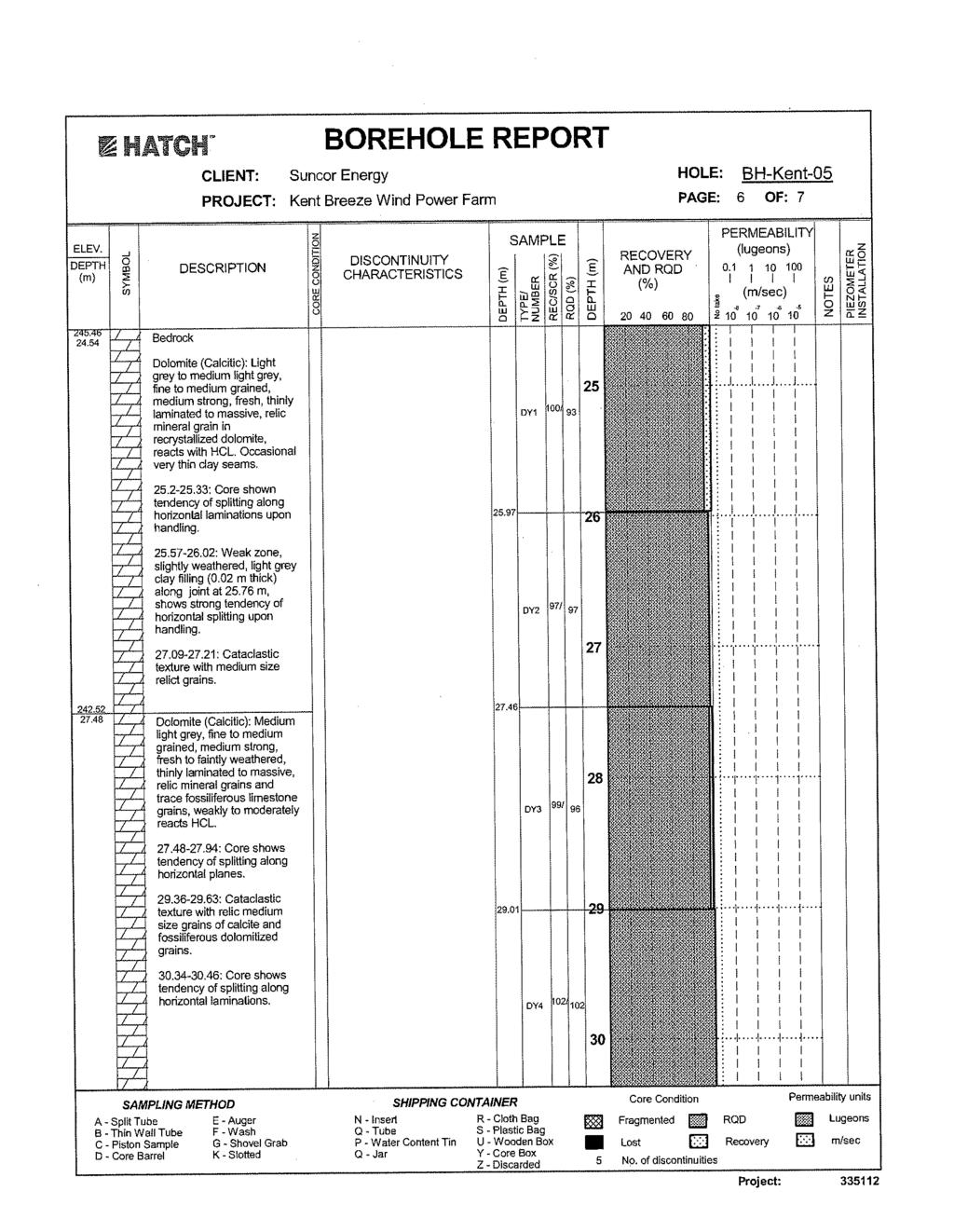
74
75
76
77
78
79
80
81
82
83
84
85
86
87
88
89
90
91
92
93
94
95
96
97

98

99
100 IBI GROUP CONSTRUCTION PLAN REPORT Kent Breeze Corporation MacLeod Windmill Project Inc. KENT BREEZE WIND FARMS APPENDIX 3C TECHNICAL MEMORANDUM (WATER CROSSINGS)

101 DATE July 22, 2010 PROJECT No TO Brad West Suncor Energy Products Ltd. CC Christopher Scott FROM Andrew Evers KENT BREEZE WIND FARMS CONSTRUCTION PLAN REPORT AUTHORIZATION AND APPROVAL REQUIREMENTS FOR WATERCOURSE CROSSINGS Introduction Kent Breeze Corporation and MacLeod Windmill Project Inc. (the Proponent) are proposing to develop a wind energy project in the northern portion of the Municipality of Chatham-Kent. The Kent Breeze Wind Farms Project (the Project) is a Class 4 wind facility consisting of eight wind turbines with a total nameplate generating capacity of 20 megawatts (MW). The Project will involve the construction of turbines, access roads, and related electrical infrastructure to connect with the Hydro One overhead transmission corridor located on approximately 436 hectares (ha) of land. This technical memorandum summarizes correspondence between IBI Group (the Consultant for the Proponent) and the associated Conservation Authorities regarding approvals and authorizations required for the construction of the Project. Specifically, authorizations and approvals, or permission will be required for directional drilling under the Shaw Ferguson and Mason Drains for the installation of underground cabling. Additional contact was conducted with the SCRCA and LTVCA outside of conversations with the MOE. Correspondence with the LTVCA indicates that a permit will not be required for direct drilling under the Mason Drain, but activities must follow the Department of Fisheries and Oceans (DFO) Operational Statement for High Power Direction Drilling (DFO, 2010). Correspondence with the SCRCA indicates that a permit will be required for direct drilling under the Shaw Ferguson Drain. Further details regarding correspondence with the local CAs is presented below and correspondence is attached. Details of the site preparation and construction activities and the associated environmental effects on watercourses can be found in the Construction Plan Report. The authorization and approvals presented here are based on the details provided in the Construction Plan Report. Approvals and Authorizations Site preparation and construction activities for the Project are not expected to have negative effects on the agricultural drains located within the Project Area. However, where improvements or construction of new water Golder Associates: Operations in Africa, Asia, Australasia, Europe, North America and South America
KENT BREEZE WIND FARMS
 Decommissioning Plan Report MAY 2010 TABLE OF CONTENTS 1. INTRODUCTION... 1 2. DECOMMISSIONING PROCESS DESCRIPTION... 2 3. SITE RESTORATION... 3 4. EXCESS MATERIALS AND WASTE MANAGEMENT... 4 5. MANAGING
Big Thunder Wind Park
 Construction Plan Report DRAFT Prepared by: M.K. Ince and Associates Ltd. May 18, 2010 TABLE OF CONTENTS BIG THUNDER WIND PARK... 1 1 PROJECT OVERVIEW... 1 1.1 PROJECT SCHEDULE... 2 2 CONSTRUCTION ACTIVITIES...
KENT BREEZE WIND FARMS
 Design and Operations Report MAY 2010 TABLE OF CONTENTS 1. INTRODUCTION... 1 2. SITE PLANS... 1 3. FACILITY DESIGN... 2 4. FACILITY OPERATIONS... 2 5. ENVIRONMENTAL EFFECTS MONITORING PLAN... 3 6. EMERGENCY
Draft Air Quality & Odour Net Effects Analysis & Comparative Evaluation Report
 Clean Harbors Canada Inc. Lambton Landfill Expansion Environmental Assessment Draft Air Quality & Odour Net Effects Analysis & Prepared By: JANUARY, 2014 Executive Summary Two expansion alternatives were
Oweninny Wind Farm. Oweninny Environmental Impact Statement Appendix 5B
 Oweninny Wind Farm Oweninny Environmental Impact Statement Appendix 5B Access Tracks, Hardstanding Areas, Electrical Compounds, Borrow Pit And Cable Laying Construction Method Statement Copyright ESB International
Subsection or plan to be revised: 7-1, 7-8, , On page(s): 27-31(2006), 48-49(2003)
: 27-31(2006), 48-49(2003)") Proposed Revision To: Standard Specifications For Public Works Construction Standard Plans For Public Works Construction Public Works Standards, Inc. AGC Southern California Regional Office 1906 West Garvey
Proposed Revision To: Standard Specifications For Public Works Construction Standard Plans For Public Works Construction Public Works Standards, Inc. AGC Southern California Regional Office 1906 West Garvey
Background Information & Mitigation Guidelines MANURE STORAGE IMPROVEMENTS and MORTALITY MANAGEMENT
 Background Information & Mitigation Guidelines MANURE STORAGE IMPROVEMENTS and MORTALITY MANAGEMENT I. BACKGROUND FOR MANURE STORAGE AND HANDLING SYSTEMS Supplementary Information Form on sizing and safety
Preferred Elevated Tank Site
 Preferred Elevated Tank Site Preferred Site No. 3 is on private property owned by Hopewell Developments. Approximately 5 acres of land will be required, including lands required for a permanent access
Chapter CONSTRUCTION SITE EROSION CONTROL
 Chapter 19.30 CONSTRUCTION SITE EROSION CONTROL Sections: 19.30.010 When required. 19.30.020 Definitions. 19.30.030 Technical Standards 19.30.040 Erosion and sediment control performance standards for
F3. Final Air Quality & Odour Net Effects Analysis & Comparative Evaluation Report
 F3. Final Air Quality & Odour Net Effects Analysis & Comparative Evaluation Report Clean Harbors Canada Inc. Lambton Landfill Expansion Environmental Assessment Air Quality & Odour Net Effects Analysis
F3. Draft Air Quality & Odour Net Effects Analysis & Comparative Evaluation Report
 F3. Draft Air Quality & Odour Net Effects Analysis & Comparative Evaluation Report Clean Harbors Canada Inc. Lambton Landfill Expansion Environmental Assessment Draft Air Quality & Odour Net Effects Analysis
Short-term (Construction) Impacts and Potential Mitigation
 Impacts and Potential Mitigation") 4 Short-term (Construction) Impacts and Potential Mitigation CHAPTER 4. SHORT-TERM (CONSTRUCTION) IMPACTS AND POTENTIAL MITIGATION This chapter describes short-term (construction) impacts that could result
4 Short-term (Construction) Impacts and Potential Mitigation CHAPTER 4. SHORT-TERM (CONSTRUCTION) IMPACTS AND POTENTIAL MITIGATION This chapter describes short-term (construction) impacts that could result
AMHERST ISLAND WIND ENERGY PROJECT PROPERTY LINE SETBACK ASSESSMENT REPORT. File No April Prepared for:
 PROPERTY LINE SETBACK ASSESSMENT REPORT File No. 160960595 April 2013 Prepared for: Windlectric Inc. 2845 Bristol Circle Oakville ON L6H 7H7 Prepared by: Stantec Consulting Ltd. Suite 1 70 Southgate Drive
SOUTH BRANCH WIND FARM DECOMMISSIONING REPORT
 SOUTH BRANCH WIND FARM DECOMMISSIONING REPORT Report 7 of 9 March 26, 2012 South Branch Windfarm Inc. 226 ½ James Street North, Unit A Hamilton, Ontario L8R 2L3 Tel: 905-528-1747 Fax: 866-203-6516 Email:
Factor Potential Effects Mitigation Measures
 Natural Environment No impacts of provincial significance to the natural environment are anticipated for the rapid transit project. Other impacts and how they will be mitigated are outlined in the table
K2 WIND POWER PROJECT DECOMMISSIONING PLAN REPORT. Prepared by: K2 Wind Ontario Limited Partnership Suite 105, 100 Simcoe Street Toronto, ON M5H 3G2
 K2 WIND POWER PROJECT DECOMMISSIONING PLAN REPORT Prepared by: K2 Wind Ontario Limited Partnership Suite 105, 100 Simcoe Street Toronto, ON M5H 3G2 In association with: Stantec Consulting Ltd.; SENES Consultants
Alberta Transportation The City of Edmonton The City of Calgary
 Alberta Transportation The City of Edmonton The City of Calgary PUBLISHING INFORMATION TITLE: PREPARED BY: DOCUMENT HOLDER: Environmental Construction Operations (ECO) Plan Framework Instructions for
RE: Modifications to Suncor Energy Adelaide Wind Project Location
 Ministry of Natural Resources Ministère des Richesses naturelles Renewable Energy Operations Team 300 Water Street Peterborough, Ontario K9J 8M5 October 23, 2012 Suncor Energy Products Inc. 150 6th Avenue
Final Construction Plan Report Belle River Wind Project
 Prepared by: AECOM 105 Commerce Valley Drive West, Floor 7 905 886 7022 tel Markham, ON, Canada L3T 7W3 905 886 9494 fax www.aecom.com Project Number: 60321891 Date: May, 2015 Table of Contents 1. Introduction...
New York Community Solar Facility Decommissioning Plan
 New York Community Solar Facility Decommissioning Plan July 2017 Prepared For: Town of Dryden, NY Delaware River Solar 33 Irving Place, Suite 1090 New York, NY 10003 Table of Contents Page 1. Introduction
Schedule A DISTRICT OF MAPLE RIDGE Watercourse Protection Bylaw
 Schedule A DISTRICT OF MAPLE RIDGE Watercourse Protection Bylaw 6410 2006 The Erosion and Sediment Control plan should seek (i) to protect the soil surface from erosion where possible and (ii) capture
Theme Comment Response. All neighbours should be entitled to revenue sharing, not just those who have signed an option agreement with Suncor.
 The following table summarizes the comments provided during and after the October 3 rd, 2012 Public Meeting for the Suncor Energy Adelaide Wind Project (the Project) via the questionnaire and email. The
Environmental Assessment Matrix
 For FCC Use Only Date: Customer Name: Environmental Assessment Matrix Loan Number: Please complete each question. Some answers may require additional information. Attach additional documentation where
5 ENVIRONMENTAL ASSESSMENT AND RESIDUAL EFFECTS
 5 ENVIRONMENTAL ASSESSMENT AND RESIDUAL EFFECTS The following section describes the potential interactions between the proposed Digby Wind Power Project and the biophysical and socio-economic environment,
Canadian Solar Developers Ltd.
 Canadian Solar Developers Ltd. Type of Document Draft Report Project Name Proposed Ground Mount Solar Facility L.P #5 8338 Scotchmere Drive, Strathroy, ON OPA FIT Program: FIT-FL67GB5 Project Number V00002250-00
Technical Data
 4906-17-05 Technical Data (A) PROJECT AREA SITE have occurred in this section. (1) Geography and Topography have occurred in this section. (2) Aerial Photography have occurred in this section. (3) Site
Re: Erosion Control Report and Drawings Requirements Accompanying Document
 Re: Erosion Control Report and Drawings Requirements Accompanying Document This document was created to help engineers and other design staff to better understand, meet and exceed the erosion control requirements
 GENERAL NOTES ENGINEERS OVERSIGHT 1. ALL ELEVATIONS, DIMENSIONS, ALIGNMENTS AND ORIENTATION OF ALL ELEMENTS SHOWN IN THE PLANS MUST BE APPROVED BY THE ENGINEER OR ENGINEER'S REPRESENTATIVE ( REP ENGINEER
EXCAVATION & BACKFILLING GUELPH TRANSIT OPERATIONS & MAINTENANCE SECTION WATSON ROAD FACILITY PAGE 1 OF 6 WATER RECLAMATION PROJECT JUNE 2013
 GUELPH TRANSIT OPERATIONS & MAINTENANCE SECTION WATSON ROAD FACILITY PAGE 1 OF 6 PART 1 GENERAL 1.1 Description The Work of this Section shall be all labour, materials, equipment and supervision necessary
Activities that may Require Permit/Approval. Permit/Approval Required Electrical Safety Authority. Approval (CAA) process.
 process.") 10.0 Table 10-1 represents a preliminary list of anticipated permits and approvals required to implement the Project and additional details regarding each anticipated permit/approval including the agency
10.0 Table 10-1 represents a preliminary list of anticipated permits and approvals required to implement the Project and additional details regarding each anticipated permit/approval including the agency
DESCRIPTION OF THE PROJECT CHANGE
 Stantec Consulting Ltd. 70 Southgate Drive, Unit 1 Guelph, Ontario N1G 4P5 September 19, 2012 Stantec File: 160960584 Ministry of the Environment Environmental Approvals Access & Service Integration Branch
Environmental Assessment Registration Destination RV Resort
 Environmental Assessment Registration Destination RV Resort Nine Island Pond South,Newfoundland and Labrador Prepared for: Department of Environment and Conservation Environmental Assessment Division Prepared
BEAVER CREEK SOLAR FARM
 BEAVER CREEK SOLAR FARM Municipality of Central Elgin, County of Elgin DECOMMISSIONING PLAN OCTOBER 2010 October 2010 1. DECOMMIS S IONING P LAN... 3 1.1 Purpose... 3 2. DECOMMIS S IONING P ROCESS DESCRIPTION...
Order of road works and servicing construction to be carried out in accordance with the staged contract construction sequence specified below.
 SEDIMENT CONTROL NOTES 1.0 GENERAL 1.1 The Developer and Contractor shall comply with the requirements of all regulatory authorities, federal, provincial and municipal government departments including
AMHERST ISLAND WIND ENERGY PROJECT - RENEWABLE ENERGY APPROVAL AMENDMENT MODIFICATION REPORT #4. Appendix B: WAWBR Revised Figures and Tables
 AMHERST ISLAND WIND ENERGY PROJECT - RENEWABLE ENERGY APPROVAL AMENDMENT MODIFICATION REPORT #4 Appendix B: WAWBR Revised Figures and Tables 355000 360000 370000 4895000 Fralick Townline Withers County
E. CONSTRUCTION PROCEDURES
 E. CONSTRUCTION PROCEDURES The Project facilities would be constructed in accordance with established electric utility practices, best management practices, final engineering plans, CL&P s specifications
GENERAL SPECIFICATION FOR ENVIRONMENTAL PROTECTION FOR CONSTRUCTION IN WATERBODIES AND ON WATERBODY BANKS
 ONTARIO PROVINCIAL STANDARD SPECIFICATION METRIC OPSS.PROV 182 NOVEMBER 2012 GENERAL SPECIFICATION FOR ENVIRONMENTAL PROTECTION FOR CONSTRUCTION IN WATERBODIES AND ON WATERBODY BANKS TABLE OF CONTENTS
Prepared for: Prepared by:
 File No. 160960710 Prepared for: Suncor Energy Products Inc. 150 6 th Avenue SW Calgary AB T2P 3E3 Prepared by: Stantec Consulting Ltd. Suite 1-70 Southgate Drive Guelph ON N1G 4P5 Executive Summary Suncor
SIEA LUNGGA POWER STATION RETAINING WALL
 SIEA LUNGGA POWER STATION RETAINING WALL 1. Glossary In this scope of work the following abbreviations and definitions apply. Term AS 3000 AS 3600 AS 3700 Boundary Lines AS 4678 Brick Works Contract Contractor
Amherst Island Wind Energy Project - Renewable Energy Approval Amendment Modification Report
 Amherst Island Wind Energy Project - Renewable Energy Approval Amendment Modification Report Prepared for: Windlectric Inc. 2845 Bristol Circle Oakville ON L9H 7H7 Prepared by: Stantec Consulting Ltd.
Chapter 750 WIND POWER GENERATION FACILITIES
 Chapter 750 WIND POWER GENERATION FACILITIES 750.01 Purpose 750.02 Definitions 750.03 Designated Areas 750.04 Permitted Uses 750.05 Conditional Uses 750.06 Construction Standards 750.07 Application Requirements
Amherst Island Wind Energy Project - Renewable Energy Approval Amendment Modification Report #4
 Amherst Island Wind Energy Project - Renewable Energy Approval Amendment Modification Report #4 Prepared for: Windlectric Inc. 2845 Bristol Circle Oakville ON L9H 7H7 Prepared by: Stantec Consulting Ltd.
CF50/100 KW TURBINE ACCESS ROAD, CRANE PLATFORM, CONCRETE, AND LIFTING SPECIFICATIONS C&F GREEN ENERGY REVISION PREPARED BY APPROVED BY DATE
 CF50/100 KW TURBINE ACCESS ROAD, CRANE PLATFORM, CONCRETE, AND LIFTING SPECIFICATIONS C&F GREEN ENERGY REVISION PREPARED BY APPROVED BY DATE 001 First Draft W Hession 12.02.2014 Introduction This document
Welcome To The Public Open House For The Wainfleet Wind Energy Project August 24, 2010
 Welcome To The Public Open House For The Wainfleet Wind Energy Project August 24, 2010 Objectives of Open House: Introduce Wainfleet Wind Energy Inc. and IPC Energy. Present an overview of Wainfleet Wind
Water Pollution Control for Work in Sensitive Areas
 Water Pollution Control for Work in Sensitive Areas 10-1. WATER POLLUTION CONTROL The Contractor is advised that failure to fully comply with the provisions of this Section, and all requirements listed
Renewable Energy Approval Documents Cochrane Solar Project Executive Summary January 25, 2013
 Renewable Energy Approval Documents Cochrane Solar Project Executive Summary January 25, 2013 Cochrane Solar Project Executive Summary Northland Power Inc. Cochrane Solar Project January 25, 2013 Executive
Preface. MNR # Queen s Printer for Ontario, 2012 ISBN (PRINT) ISBN (PDF)
 ISBN (PDF)") Preface In 2008, the inter-agency Drainage Act & Section 28 Regulations Team (DART) was established by the Ministry of Natural Resources (MNR) and the Ministry of Agriculture, Food and Rural Affairs (OMAFRA)
Preface In 2008, the inter-agency Drainage Act & Section 28 Regulations Team (DART) was established by the Ministry of Natural Resources (MNR) and the Ministry of Agriculture, Food and Rural Affairs (OMAFRA)
Introduction- Category 9
 Introduction- Category 9 These Standards 1 have been developed to support the Aggregate Resources Act as amended by Bill 52, the Aggregate and Petroleum Resources Statute Law Amendment Act, 1996. There
Linfairn Wind Farm Addendum Chapter A3: Project Description
 A3. PROJECT DESCRIPTION 3.1 Introduction This chapter provides a description of the changes to the Project since the ES was published. An outline Construction Environmental Management Plan (CEMP) is included
The Manitoba Water Services Board SECTION Standard Construction Specifications September 2013 Page 1 of 8
 September 2013 Page 1 of 8 Part 1 General 1.1 DESCRIPTION OF WORK.1 The work described hereunder shall consist of the construction of sewer and/or water pipeline or watermain crossings of rivers and other
PRECAST CONCRETE GIRDER ERECTION
 7.1 Precast Concrete Girder Erection - General Erection of precast concrete girders includes transporting the girders to the site, handling and temporary storage, installing anchor bolts, shear blocks
ENVIRONMENTAL ASSESSMENT REGISTRATION
 ENVIRONMENTAL ASSESSMENT REGISTRATION PORT HARMON CHANNEL AND HARBOUR DREDGING Submitted to: Department of Environment Environmental Assessment Division May 2004 ENVIRONMENTAL ASSESSMENT REGISTRATION PORT
City of Doral 8401 NW 53 rd Ter. Doral, FL 33166
 City of Doral 8401 NW 53 rd Ter. Doral, FL 33166 Project Address: (305) 593-6700 Permit Number: National Pollution Discharge Elimination System (NPDES) Construction Site Erosion and Sedimentation Control
SECTION UNCLASSIFIED EXCAVATION AND GRADING
 SECTION 02210 UNCLASSIFIED EXCAVATION AND GRADING PART 1 GENERAL 1.1 DESCRIPTION Work in this section includes the excavation, undercut excavating, grading, earthwork and compaction required as shown on
Mohawk College Hamilton, ON. Project Description Report. Fennell Campus Wind Project
 Mohawk College Hamilton, ON Fennell Campus Wind Project H336493-0000-07-124-0001 Rev. C September 24, 2010 Project Report Mohawk College Fennell Campus Wind Project September 24, 2010 Table of Contents
Imperial s Sarnia Products Pipeline
 Imperial s Sarnia Products Pipeline Waterdown to Finch Project Community Information Session Imperial s Waterdown to Finch Project Important infrastructure to the Greater Toronto and Hamilton Area (GTHA).
KENT BREEZE WIND FARMS
 Kent Breeze Corporation REA Project Description Report MAY 2010 TABLE OF CONTENTS 1. GENERAL INFORMATION... 1 1.1 Name of Project... 1 1.2 Project Location... 1 1.3 Contacts... 2 1.4 Authorizations Required...
Willow Ridge Wind Project Frequently Asked Questions. Popular Questions Who is the developer of the proposed project?
 Willow Ridge Wind Project Frequently Asked Questions Popular Questions Who is the developer of the proposed project? Algonquin Power Co./ Liberty Power Co. is the company proposing the project and, if
SANKO GEOTHERMAL POWER PROJECT TRAFFIC MANAGEMENT PLAN
 Draft A.0 January 10, 2018 Version Revision Date SANKO GEOTHERMAL POWER PROJECT Prepared by Checked by Approved by Muhsin Dervişoğulları Environmental Manager Project Manager General Manager of Geothermal
Project Update. Gas to Great Island Power Station
 Project Update Gas to Great Island Power Station Introduction The Transmission System Operator, Gaslink, on behalf of Endesa Ireland Ltd., has requested Bord Gáis Networks to design for a new gas supply
SECTION TRENCHING, BACKFILLING, COMPACTION AND GENERAL GRADING
 PART 1 GENERAL SECTION 02221 TRENCHING, BACKFILLING, COMPACTION AND GENERAL GRADING 1.01 SECTION INCLUDES A. Excavation, dewatering and backfilling with compaction of trenches for pipes, conduits, channels
Decommissioning Report East Durham Wind Energy Centre
 NextEra Energy Canada, ULC East Durham Wind Energy Centre Prepared by: GENIVAR Inc. 500 600 Cochrane Drive 905-475-7270 tel Markham, ON, Canada L3R 5K3 905-475-5994 fax www.genivar.com Project Number:
SPECIFICATIONS FOR STRUCTURAL EXCAVATION
 SPECIFICATIONS FOR STRUCTURAL EXCAVATION 1.0 DESCRIPTION The Work shall consist of:.1 Excavation and removal of material for the placement of foundations, substructure units, approach slabs, transition
Building Better Storm Water Quality
 Building Better Storm Water Quality s Storm Water Pollution Prevention Guidelines for Development Construction Projects City of El Segundo 350 Main Street (310) 524-2380 El Segundo, California 90245 Introduction
Please print or type.
 SOIL EROSION AND SEDIMENTATION CONTROL PERMIT APPLICATION 6-18-07 Ann kjjkjkff- ANN ARBOR CHARTER TOWNSHIP 3792 Pontiac Trail, Ann Arbor, Michigan 48105-9656 Phone (734) 663-3418 Website: www.aatwp.org
Georgetown Water Storage Class Environmental Assessment Study
 Georgetown Water Storage Class Environmental Assessment Study Public Information Centre Cedarvale Community Centre 181-185 Main Street South Thursday, September 4th, 2008 6:30 p.m. 8:30 p.m. Why are we
Grant County Wind: Revised Decommissioning Plan
 Grant County Wind: Revised Decommissioning Plan Roseville Township - Grant County, MN Initially Prepared by: Mr. Jeff Bendel Vice President of Construction, Juhl Wind August 1, 2010 Revised April 14, 2014
Design-Build for Improvements to the Amherst Island Ferry Docks Public Information Centre April 2017 Please Sign In
 WELCOME Design-Build for Improvements to the Amherst Island Ferry Docks Public Information Centre April 2017 Please Sign In PURPOSE OF THIS MEETING Rankin Construction Inc. (RCI) and their design consultant
EXCAVATION, TRENCHING & BACKFILLING..1 The section refers to excavation, trenching, backfilling and all Work pertaining thereto.
 CITY OF BRAMPTON LANDSCAPE SPECIFICATIONS SECTION 02315-1 PART 1 GENERAL 1.1 Description of Work.1 The section refers to excavation, trenching, backfilling and all Work pertaining thereto. 1.2 Related
METHOD STATEMENT. MVV O&M GmBH, South West Devon Waste Partnership & Kier Construction Limited. Document No: CMS/ E0788 /003 FOR
 METHOD STATEMENT, South West Devon Waste Partnership & Kier Construction Limited Document No: CMS/ E0788 /003 FOR Construction of Bull Point Access Road DOCUMENT HISTORY DATE ISSUE COMMENTS ORIGINATOR
ENVIRONMENTAL GUIDANCE NOTES: CONSTRUCTION ENVIRONMENTAL MANAGEMENT PLAN (CEMP)
") ENVIRONMENTAL GUIDANCE NOTES: CONSTRUCTION ENVIRONMENTAL MANAGEMENT PLAN (CEMP) Disclaimer: The information contained in this communication document is intended solely for the use of guidance cannot be
ENVIRONMENTAL GUIDANCE NOTES: CONSTRUCTION ENVIRONMENTAL MANAGEMENT PLAN (CEMP) Disclaimer: The information contained in this communication document is intended solely for the use of guidance cannot be
GENERAL NOTES REQUIRED NOTES ON ALL PLANS
 GENERAL NOTES REQUIRED NOTES ON ALL PLANS ALL MATERIALS, WORKMANSHIP AND CONSTRUCTION SHALL CONFORM TO THE CURRENT CITY OF SANTA ROSA DESIGN AND CONSTRICTIOIN STANDARDS AND CONSTRUCTION SPECIFICATIONS
ADMINISTRATION OF AGGREGATE SOURCES INCLUDING EARTH AND ROCK BORROW SOURCES. Special Provision No. 199S38 March 2003
 ADMINISTRATION OF AGGREGATE SOURCES INCLUDING EARTH AND ROCK BORROW SOURCES Special Provision No. 199S38 March 2003 The following MTO specification is not based on or referenced to an OPS Specification.
SECTION GENERAL EXCAVATION
 02210-1 of 11 SECTION 02210 GENERAL EXCAVATION 02210.01 GENERAL A. Description 1. General excavation shall include but not necessarily be limited to, excavation and grading for general site work, roadways,
Generic Spill Contingency Plan
 Generic Spill Contingency Plan Updated April 15 th, 2015 TABLE OF CONTENTS 1.0 INTRODUCTION... 2 1.1 Purpose of the Spill Contingency Plan... 2 1.2 Contents of the Spill Contingency Plan... 2 1.3 Harold
GENERAL SPECIFICATION FOR ENVIRONMENTAL PROTECTION FOR CONSTRUCTION IN AND AROUND WATERBODIES AND ON WATERBODY BANKS
 ONTARIO PROVINCIAL STANDARD SPECIFICATION METRIC OPSS.PROV 182 APRIL 2017 GENERAL SPECIFICATION FOR ENVIRONMENTAL PROTECTION FOR CONSTRUCTION IN AND AROUND WATERBODIES AND ON WATERBODY BANKS TABLE OF CONTENTS
Background Information MANURE STORAGE IMPROVEMENTS, MANURE COMPOSTING and MORTALITY MANAGEMENT
 I Background Information MANURE STORAGE IMPROVEMENTS, MANURE COMPOSTING and MORTALITY MANAGEMENT This information package has been prepared specifically for producers who have expressed interest in utilizing
Appendix C3 Spill Prevention, Containment, and Countermeasures Plan Framework
 Appendix C3 Spill Prevention, Containment, and Countermeasures Plan Framework THIS PAGE INTENTIONALLY LEFT BLANK TABLE OF CONTENTS C3.1 Purpose... C3-1 C3.2 Responsibility of Implementation... C3-2 C3.3
EROSION AND SEDIMENTATION CONTROL SECTION 1 - GENERAL 1.1 SUMMARY
 31 25 00 EROSION AND SEDIMENTATION CONTROL SECTION 1 - GENERAL 1.1 SUMMARY A. Erosion and sedimentation control shall be provided by the Contractor for all areas of the site denuded or otherwise disturbed
Grand Bend Wind Farm. Construction Plan Report. Grand Bend Wind Limited Partnership Northland Power Inc., as agent
 Grand Bend Wind Farm Grand Bend Wind Limited Partnership Northland Power Inc., as agent Grand Bend Wind Farm Prepared By: Neegan Burnside Ltd. 292 Speedvale Avenue West Unit 20 Guelph ON N1H 1C4 Prepared
Introduction-Category 3
 Introduction-Category 3 These Standards 1 have been developed to support the Aggregate Resources Act as amended by Bill 52, the Aggregate and Petroleum Resources Statute Law Amendment Act, 1996. There
CONSTRUCTION SPECIFICATION FOR NOISE BARRIER SYSTEMS
 ONTARIO PROVINCIAL STANDARD SPECIFICATION METRIC OPSS 760 NOVEMBER 2014 CONSTRUCTION SPECIFICATION FOR NOISE BARRIER SYSTEMS TABLE OF CONTENTS 760.01 SCOPE 760.02 REFERENCES 760.03 DEFINITIONS 760.04 DESIGN
C. Foundation stabilization for pipe and utility structures.
 PART 1 - GENERAL 1.1 SECTION INCLUDES A. Excavating, backfilling, and compacting for utilities, including pipe, structures, and appurtenances. B. Control of water in trenches. C. Foundation stabilization
Nottawasaga Valley Conservation Authority
 Nottawasaga Valley Conservation Authority PROCEDURAL GUIDELINE FOR THE PLACEMENT OF LARGE QUANTITIES OF FILL Effective: October 28, 2011 Nottawasaga Valley Conservation Authority 8195 8th Line, Utopia,
ENVIRONMENTAL SCREENING REPORT
 ENVIRONMENTAL SCREENING REPORT Pursuant to the Canadian Environmental Assessment Act (CEA Act) SCREENING SUMMARY TransCanada PipeLines Limited (TransCanada) is proposing to conduct a contaminant sampling
Section Safety Section Cleanup. None Required
 January 2000 Page 1 of 6 PART 1 GENERAL 1.01 OTHER CONTRACT DOCUMENTS 1.02 DESCRIPTION OF WORK 1.03 RELATED SECTIONS PART 2 PRODUCTS The General Conditions of the Contract, General Requirements, and Supplemental
Appendix B. Summary of Potential Environmental Effects and the Environmental Effects Monitoring Plan
 Appendix B Summary of Potential Environmental Effects and the Environmental Effects Monitoring Plan Heritage and Archaeological Resources Protected Properties and Heritage Resources 24 built heritages
MINNEHAHA CREEK WATERSHED DISTRICT BOARD OF MANAGERS REVISIONS PURSUANT TO MINNESOTA STATUTES 103D.341. Adopted April 24, 2014 Effective June 6, 2014
 MINNEHAHA CREEK WATERSHED DISTRICT BOARD OF MANAGERS REVISIONS PURSUANT TO MINNESOTA STATUTES 103D.341 Adopted April 24, 2014 Effective June 6, 2014 EROSION CONTROL RULE 1. POLICY. It is the policy of
We are here to:
 Welcome! We are here to: Provide an overview and update of the proposed wind energy project Introduce the Project team Review the wind project development process Answer your questions NextEra Energy Resources
ADDENDUM #1 TO THE SPECIFICATION FOR THE CONSTRUCTION OF THE 115KV STONEBREAK RD. TRANSITION STATION THE TOWN OF MALTA AND A PORTION OF THE 115KV
 ADDENDUM #1 TO THE SPECIFICATION FOR THE CONSTRUCTION OF THE 115KV STONEBREAK RD. TRANSITION STATION IN THE TOWN OF MALTA AND A PORTION OF THE 115KV LUTHER FOREST STATION IN THE TOWN OF STILLWATER SARATOGA
Welcome to our Information Centre
 Welcome to our Information Centre Overbrook to Riverview Transmission Line Upgrade September 21 and 22, 2016 Purpose of the Information Centre Meet our project team and learn more about: The proposed project
CONSTRUCTION SPECIFICATION FOR CONCRETE BARRIERS
 ONTARIO PROVINCIAL STANDARD SPECIFICATION METRIC OPSS 553 FEBRUARY 1991 CONSTRUCTION SPECIFICATION FOR CONCRETE BARRIERS 553.01 SCOPE 553.02 REFERENCES 553.03 DEFINITIONS TABLE OF CONTENTS 553.04 SUBMISSION
Erosion & Sedimentation Control Policy
 Issue Date 10/22/2010 Page 1 of 8 Erosion & Sedimentation Control Policy Introduction: Soil erosion is the removal of soil by water, wind, ice or gravity and sediment deposition occurs when the rate of
B. Subsurface data is available from the Owner. Contractor is urged to carefully analyze the site conditions.
 SECTION 31 23 33 - TRENCHING, BACKFILLING AND COMPACTION PART 1 - GENERAL 1.1 SCOPE A. This Section specifies the requirements for excavating and backfilling for storm sewer, sanitary sewer, water distribution
SOUTH BRANCH WIND FARM PROJECT DESCRIPTION REPORT
 SOUTH BRANCH WIND FARM PROJECT DESCRIPTION REPORT Report 1 of 9 May 31, 2012 South Branch Windfarm Inc. 226 ½ James Street North, Unit A Hamilton, Ontario L8R 2L3 Tel: 905-528-1747 Fax: 866-203-6516 Email:
9.2 Definitions. The following terms are defined, for purposes of Section 9, as follows:
 SECTION 9. COMMERCIAL WIND ENERGY FACILITIES 9.1 Purpose. The purpose of this Section 9 of the Zoning Bylaw is to provide by special permit for the construction and operation of commercial wind facilities
CONSTRUCTION SPECIFICATION FOR THE INSTALLATION OF ELECTRICAL CHAMBER
 ONTARIO PROVINCIAL STANDARD SPECIFICATION METRIC OPSS 602 MARCH 1993 CONSTRUCTION SPECIFICATION FOR THE INSTALLATION OF ELECTRICAL CHAMBER 602.01 SCOPE 602.02 REFERENCES 602.05 MATERIALS TABLE OF CONTENTS
March 9, Supplementary Spring Blanding s Turtle Mitigation Protocol. Amherst Island Wind Project. March 9, Prepared for: Windlectric Inc.
 March 9, 2018 Amherst Island Wind Project Supplementary Spring Blanding s Turtle Mitigation Protocol March 9, 2018 Prepared for: Windlectric Inc. Prepared by: Stantec Consulting Ltd. Reviewed and Approved
Comprehensive Study Scoping Document. for Lower Mattagami Hydroelectric Complex Redevelopment CEAR Reference Number:
 Comprehensive Study Scoping Document for Lower Mattagami Hydroelectric Complex Redevelopment CEAR Reference Number: 07-03-26302 Prepared pursuant to Subsection 21(1) of the Canadian Environmental Assessment