Dr-Ing Angelos Markopoulos, Lecturer
|
|
|
- Erica Barber
- 6 years ago
- Views:
Transcription


1 Dr-Ing Angelos Markopoulos, Lecturer National Technical University of Athens Greece Rzeszow, Poland 16 September 2015
2 By the term machining, processes that shape parts by removing unwanted material, are described. Unwanted material is carried away from the workpiece usually in the form of a chip; evaporation or ablation may take place in some machining operations. The more narrow term cutting is used to describe the formation of a chip via the interaction of a tool in the form of a wedge with the surface of the workpiece, given that there is a relative movement between them. Precision Machining 2

3 Surveys indicate that 15 % of all mechanical components value, manufactured in the world, comes from machining operations and that annual expenditure on machine tools and cutting tools are several billion for industrially developed countries. If labor, machinery, tools and materials costs, social impact from employment in machining related jobs and technological developments becoming available from machining advances are considered, then the importance of machining and its impact on today s industry and society is quite obvious. Precision Machining 3
4 Trends in manufacturing technology are driven by two very important factors, which are closely interconnected, namely better quality and reduced cost. Modern industry strives for products with dimensional and form accuracy and low surface roughness at acceptable cost; an extreme paradigm being micromachining of miniaturized components. From an economic point of view, machining cost reduction achieved through the increase of material removal rate and tool life without compromising surface integrity even for hard-tomachine materials is highly desirable, e.g. precision turning of hardened steels by CBN tools at increased speeds or as it is usually referred in the literature High Speed Hard Turning. Understanding chip formation mechanisms and predicting cutting forces are of the greatest importance on realizing both the above goals and one way to achieve this, probably the most used one, is modeling. Precision Machining 4
5 Machining of metals, although is one of the oldest and very important manufacturing process, has been subjected to systematic study for a little more than a century. Almost for the second half of this time period, studying of metal machining is accompanied by modeling methods. The initial objective of studying and modeling metal machining was to provide a theory which, without any experimental work, would enable researchers to predict cutting performance and thus solve practical problems confronted in industry. The first analytical models set the basis for more advanced methods developed later in the course of time and when the tools for realistic computational cost and analysis time became available with computer advances. Precision Machining 5
6 In the early 1970s some pioneering works on machining modeling with the Finite Element Method (FEM) begun to find their way in scientific journals. Over the years and with the increase of computer power as well as the existence of commercial FEM software, this method has proved to be the favorite modeling tool for researchers of the field. Finite element models are used today for gaining knowledge on fundamental aspect of material removing mechanisms but more importantly for their ability to predict important parameters such as cutting forces, temperatures, stresses etc. essential for the prediction of the process outcome, the quality of the final product and in a timely and inexpensive way. Precision Machining 6


7 in sectors such as automotive industry, health and biomedicine and telecommunications. At the same time, the integration of microsystems in more applications of the aforementioned areas of interest has given a boost to micro and nanomanufacturing and thus has intensified the research pertaining to MEMS and NEMS, advanced technology, increased performance and decreased cost. Precision Machining 7


8 pertain to microfluidics, pumps and valves, micronozzles, optical components, micromolds and microholes on various materials just to name some. Precision Machining 8

 similar to those encountered in miniaturized parts.")
9 It is worth noting that precision manufacturing may refer to micromachining and the construction of miniaturized parts but may also refer to precision and ultraprecision process performed on large scale components with some features (size accuracy, tight tolerances, high surface quality etc.) similar to those encountered in miniaturized parts. Precision Machining 9

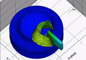
10 Orthogonal cutting represents a two-dimensional mechanical problem with no side curling of the chip considered. It represents only a small fragment of machining processes, i.e. planning or end turning of a thinwalled tube. However, it is widely used in theoretical and experimental work due to its simplicity. Because of its 2D nature many independent variables are eliminated, e.g. two cutting forces are only identified to orthogonal cutting problems. Precision Machining 10
11 There are two deformation areas distinguished in machining, namely the primary and the secondary deformation zones. In the primary deformation zone, the workpiece material crossing the OA border undergoes large deformation at high strain rates and exits the zone at OB border, work hardened. It is determined by microscopic examination and experiments that chips are produced by shear within this region. Most of the experimental studies conclude that this zone is of average thickness of about one tenth of chip thickness. Precision Machining 11

12 In the secondary deformation zone, in the contact length between the rake face of the tool and the chip, the material is deformed due to intensive interfacial friction. The secondary deformation zone is characterized by two regions, the sticking region, closer to the cutting tool tip and the sliding region, above the previous one. In the sticking region, material adheres to the tool and as a result shear within the chip is observed. Precision Machining 12
13 Both deformation zones are characterized by temperature rise due to severe plastic deformation in the primary and due to friction in the secondary deformation zone. Furthermore, high cutting speeds do not allow for heat conduction to take place and heat is concentrated at a small area around the cutting tool edge. Strain hardening due to deformation and softening due to temperature alter the chip formation characteristics in every step of its formation. The friction coefficient is very hard to be measured in the secondary deformation zone and several theories have been proposed for the calculation of friction. A simplified approach proposes that shearing in the primary deformation zone takes place along a shear plane, characterized by shear angle φ, between the shear plane and the workpiece surface. Although this single shear plane model is criticized, it is usually referred in machining handbooks due to its simplicity and it is the basis for calculating several process parameters, e.g cutting forces, through numerical modeling. Precision Machining 13


14 Merchant s Circle Lee and Shaffer s slip-line field theory Zorev s simplified model Oxley s shear zone theory Precision Machining 14
15 There are features of machining and phenomena that are considerably different in precision machining and do not allow for a simple downscaling of a theory. In precision machining and micromachining operations the depth of cut may be below 10 μm and the anticipated surface roughness only a few nm. The cutting edge can no longer be considered sharp; the cutting edge radius is comparable in size to the uncut chip thickness. At this level, Merchant s model seems unrealistic. Precision Machining 15
16 The rake angle of the tool is probably not the actual rake angle participating in the processes. There may be an effective rake angle. In this case, the elastic-plastic deformation of the workpiece material and the ploughing need to be taken into account, as well as the elastic recovery at the clearance face. Precision Machining 16

17 From the above, the existence of a minimum chip thickness that can be removed from the workpiece surface in a mechanical micromachining operation can be deducted. A stagnation point above which a chip is formed and below only elastic-plastic deformation takes place is assumed. Precision Machining 17
18 The existence of minimum chip thickness has been experimentally verified and theoretically studied. The minimum chip thickness determines whether a chip is formed or not because if the depth of cut for a microcutting operation is set below this minimum, then the cutting edge is expected to just plastically deform the workpiece material without producing a chip. This is the ploughing mechanism which except the obvious effect on the surface integrity and the quality of the finished workpiece alters significantly the cutting forces and thus the process stability in precision machining and makes the force prediction methods described hereafter ineffective. Precision Machining 18
19 Although ploughing may exist in traditional macroscale machining, its effect on the overall process may be neglected. However, this effect caused by cutting edge radius is important in precision machining. Many researchers consider this mechanism to be the main reason for the so-called size effect. Size effect is the non-linear increase in the specific energy and thus in the specific cutting force with decreasing depth of cut, which is observed in precision cutting and micromachining. Precision Machining 19
20 Precision Machining 20
21 the significantly reduced amount of imperfections, namely crystallographic defects such as grain boundaries, missing and impurity atoms and inhomogeneities present in all commercial metals, encountered when deformation takes place in a small volume. With smaller uncut chip thickness the material strength is expected to reach its theoretical value of strength. material strengthening due to an increase in the strain rate in the primary shear zone. the decrease of temperature in the tool-chip interface with decreased chip thickness. the energy required for new surface creation via ductile fracture. micro-nano-indentation and its extension to machining. The increased hardness of a material with reduced indentation depth is a result of the dependence of material flow stress on the strain gradient in the deformation zone; strain gradient plasticity can be the reason of size effect in machining because of the intense strain gradients observed. Precision Machining 21
22 Although size effect is present in metal cutting, like minimum chip thickness, it is of special importance when it pertains to precision machining and micromachining. From the literature review it is evident that many reasons for the size effect in machining and micromachining have been reported. It is not clear which of the above mechanisms is dominant or whether there could be more than one mechanism acting at the same time. Even in the case of multiple mechanisms acting together, there may be factors that alter the contribution of each factor in each case. Precision Machining 22
23 The strain rates observed are very high; this holds true for even low cutting speeds. Plastic deformation takes place in small regions, the primary and secondary deformation zones, around the cutting edge, making difficult the selection of the appropriate boundary conditions. The ploughing-shearing mechanism of micromachining further complicates the matter. Strain hardening of the workpiece material is usually neglected, although it plays a significant role, as is concluded from experimental results. Temperature rise in the region due to plastic deformation and friction induce material softening and alter the workpiece material properties in relation to strain rates and temperatures. Data for the workpiece material for varying temperature and strain rate at the levels which occur in metal machining are not easily found in the literature (non-linear analysis). Temperature rise needs to be taken into account to the various calculations performed, which means that besides the mechanical problem, a heat transfer problem must be dealt with simultaneously. The grain size of the workpiece material, which is comparable to depth of cut, needs to be addressed. Precision Machining 23
24 Finite elements appear to be the most suitable method for modeling precision machining problems. Due to its inherent characteristics it can solve non-linear problems and with advances in computers and the use of commercial software it can readily perform coupled thermomechanical analysis. Still, chip formation is difficult to be modeled. Except the physical phenomena already explained two more challenges need to be addressed. 1. The first one is to provide accurate data to the model; this is common sense however it can be problematic. 2. The second is to actually choose a finite elements method. There are different approaches or strategies proposed for metal machining modeling with FEM pertaining to formulation, treatment of friction, material behavior, iteration scheme etc. used for approximating a solution. Precision Machining 24
25 In FEM the basic principle is the replacement of a continuum by finite elements forming a mesh; this procedure is called discretization. Each finite element is simpler in geometry and therefore easier to analyze that the actual structure. Every finite element possesses nodes where the problem initial and boundary conditions are applied and the degrees of freedom are calculated; the finite elements are connected to one another in nodes. Between the nodes, problem variables are derived by interpolation. The problem variables as well as properties applied on the nodes of each element are assembled and global relations are formatted. Usually, the analysis involves a great number of algebraic equations to determine nodal degrees of freedom and that is why a personal computer is employed for processing. Precision Machining 25
26 There are two different time integration strategies in order to face non-linear and dynamic models, namely implicit and explicit schemes. The explicit approach determines the solution of the set of finite element equations by using a central difference rule to integrate the equations of motion through time. The implicit method is realized by solving the set of finite element equations, performing iterations until a convergence criterion is satisfied for each increment. The length of the time step is imposed by accuracy requirements. Precision Machining 26
27 The ones used in metal cutting FEM models are so far of three types, namely Eulerian, Lagrangian and the newer Arbitrary Lagrangian-Eulerian (ALE) analysis. In the Eulerian approach the finite element mesh is spatially fixed and covers a control volume. The material flows through it in order to simulate the chip formation. This implies that the shape of the chip, shear angle and the contact conditions must be a priori known, derived from experiments, or assumed. In the Lagrangian approach the elements are attached to the material. The material is deformed due to the action of the cutting tool and so is the mesh. This way there is formation of the chip due to deformation from the tool. Unconstrained material flow in Lagrangian formulation allows for simulations from incipient chip formation to steady-state conditions and modeling of segmented chips besides the continuous one. Precision Machining 27
28 A disadvantage of the Lagrange formulation is connected to the large mesh deformation observed during the simulation. Due to the attachment of the mesh on the workpiece material, the mesh is distorted because of the plastic deformation in the cutting zone. Such severe distortions of the mesh may result in the failure of the model as they cannot be handled by the elements applied in the mesh. Furthermore, for the formation of the chip, a chip separation criterion in front of the tool edge is applied. This procedure can be quite thorny; it has been the topic of several papers and no generally accepted criterion is adopted. The latest development in the Lagrangian formulation, an updated Lagrangian analysis, has overcome the disadvantage of a chip separation criterion by applying continuous re-meshing and adaptive meshing, dealing at the same time with the mesh distortion. Precision Machining 28
29 For precision machining, the geometrical characteristics of the tool and the workpiece greatly influence the outcome of the process. More specifically, the tool edge radius is connected to size effect, minimum chip thickness, effective rake angle, stagnation point and ploughing mechanism. A significant number of papers is dedicated to the investigation of the influence of the tool edge radius on the size effect. Precision Machining 29

30 The initial mesh of the workpiece is significant for the results the model will provide. The convergence of the numerical procedure and the accuracy of the predicted variables depend on it. The obvious is that the mesh must be able to represent accurately the workpiece geometry and be able to handle the analysis to be performed. The size, number and type of the elements used in the mesh play a significant role on the simulation outcome as well. In machining the action takes place in the primary and secondary deformation zones; the mesh in these parts of the workpiece is expected to be denser in order to obtain better geometry of the chip and also be able to cope with the strains, strain rates and temperature gradients expected there. Precision Machining 30

31 Precision Machining 31

32 Of interest is the way thermo-mechanical coupling is considered. In cutting processes heat generation originates from the two deformation zones, i.e. the primary and the secondary, due to inelastic and frictional work. The heat is conducted into the tool and chip and transferred away from the chip to the environment or the cutting fluid by convection. The above are either modeled by heat sources at the heat generation regions or usually with material and tribological models that are functions of mechanical and thermal behavior with strain, strain-rate and temperature. The associated strain hardening and thermal softening is interpreted to non-linear analysis. Precision Machining 32
33 Material modeling in machining in general and in precision machining in particular is of great importance. Especially the flow properties of the workpiece material and the corresponding equations that are included into FEM have been extensively studied. These constitutive equations describe the flow stress or instantaneous yield strength at which work material starts to plastically deform or flow; the elastic strains are much lower than plastic strains in metal cutting and so workpiece material flows plastically into the cutting zone. The constitutive models presented in the literature are mainly elasto-plastic, elasto-viscoplastic, rigid-plastic and rigidviscoplastic. Machining conditions subject workpiece material to high levels of strain, strain rate and heat which greatly influence flow stress. In the primary zone strain and temperature ranges from 1-2 and 150 o C-250 o C respectively and in the secondary deformation zone from 3 to much higher and 800 o o C, while strain rates reach values of up to 2x10 4 s -1 and 10 5 s -1 in the to zones. Precision Machining 33
34 One problem of material modeling is the lack of data for high stresses, strain rates and temperatures as the ones encountered in machining. In many cases the constitutive data are taken from standard tension tests that are not sufficient for machining processes. Dynamic experimental material tests such as Split Hopkinson Pressure Bar (SHPB) impact testing is employed. Samples are deformed under high speed compression with strain rates of up 10 5 s -1 and temperatures of up to 700 o C. However, the obtained results are often criticized: they are not sufficient for the deformation behavior of metals, especially in high speed machining; values beyond test results are calculated by interpolation. the available data are not from specialized laboratories; generally speaking SHPB requires special equipment. high temperatures in metal cutting are localized; metal cutting is a cold working process, although the chip only is of high temperature. it not clear how to correlate uniaxial impact testing results of SHPB with materials that are triaxially stressed, as in metal cutting. Precision Machining 34
35 Precision Machining 35
36 Among the most used material models is the Johnson- Cook model. It is a thermo-elasto-visco-plastic material constitutive model, described as: The equation consists of three terms the first one being the elasto-plastic term to represent strain hardening, the second is viscosity, which demonstrates that material flow stress increases for high strain rates and the temperature softening term. T α is the ambient temperature, T m the melting temperature and A, B, C, n and m are constants that depend on the material and are determined by material tests. Precision Machining 36
37 In mechanical micromachining the cutting tool radius is comparable to the size of the grains of the material being processed. Furthermore, in materials with surface defects or multi phase materials, such as cast iron, the microcutting mechanism is quite different in comparison to non-heterogeneous materials due to the encounter of the cutting tip with these features of the material during the course of the process. For example, ductile iron and two of its constituents, namely pearlite and ferrite, were modeled in the same continuum, taking into account the microstructural composition, the grain size and the distribution of each material. In another example, 1045 steel, considering its microstructure, is represented by bands or sections of a pearlite-like behavior material and a ferrite-like behavior material. Precision Machining 37


 Precision")
38 Ductile iron representation taking into account the microstructural composition, the grain size and the distribution of material phases Representation of the microstructure of 1045 steel with (a) bands and (b) sections (material A: pearlite, material B: ferrite) Precision Machining 38
39 It is worth noticing that two cases from macro machining are closely related to material modeling in the micro regime. 1. The first pertains to grinding, a precision finishing process. Although this process can be modeled in macro scale, it can also be modeled in micro scale. In the latter case the material removal mechanism of a grain of the grinding wheel is considered. 2. The second case pertains to the machining of metal matrix composite materials. The nature of these materials, a matrix material reinforced with fibers or particles of small size, is similar to the case of multiphase materials. It is clear that failure mechanisms of the composites materials in turning are different from monolithic materials; cracking of the reinforcement, debonding at the reinforcement-matrix interface, growth and coalescence of voids play an important role in the machining of composite materials. Precision Machining 39


40 Grinding Composite material turning Precision Machining 40
41 Friction modeling in the secondary deformation zone, at the interface of the chip and the rake face of the tool is of equal importance to the workpiece material modeling. It is important in order to determine cutting forces but also tool wear and surface quality. The detailed and accurate modeling is rather complicated. Many finite element models of machining assume that it is a case of classical friction situation following Coulomb s law. However, as the normal stresses increase and surpass a critical value, this equation fails to give accurate predictions. From experimental analysis it has been verified that two contact regions may be distinguished in dry machining, namely the sticking and the sliding region. Zorev s stick-slip temperature independent friction model is commonly used. In Zorev s model there is a transitional zone with distance l c from the tool tip that signifies the transition from sticking to sliding region. Precision Machining 41
42 Precision Machining 42
43 It is true that modeling with FEM is not at all trivial. Use of a commercial FEM program, however, may simplify the procedure. For the past twenty years a wide range of commercial FEM packages became available. These programs have been widely accepted by researcher since they can simplify the overall procedure of model building. Commercial FEM add to the quality and accuracy of the produced models. These programs are made by specialists who have tested them and have implemented features and procedures to accelerate the slow process of model building. Most of the software have mesh generation programs, easy to use menus for applying boundary conditions, contact algorithms, automatic remeshing, material databases etc. Some researchers, however, remain skeptical due to limitations a model can impose, e.g. a model may only be able to solve a problem implicitly or explicitly. Regarding precision machining, researchers use either in-house FEM codes, commercial packages, e.g. MSC.Marc, Ansys, Abaqus etc. or commercial packages with specific menus machining, e.g. AvantEdge. Precision Machining 43


44 Precision Machining 44
45 Hard turning, a machining operation used for the processing of hard materials such as hardened steels, has been brought into the forefront of modern metal cutting operations with the increasing demand for manufacturing high quality components, e.g., gears, shafts, bearings, dies and tools. Cutting tools employed in hard turning are made of specialized tool materials, such as cubic boron nitrite (CBN), that are able to overcome the problems experienced during the process; they possess exquisite properties, even at elevated temperatures, allowing for their application at high cutting speeds, with minimum use of cutting fluids. In addition the combination of hard turning and high speed machining is proved to be very advantageous since a great reduction in processing time can be achieved. Hard turning is very advantageous for a wide spectrum of applications and is also considered as an alternative for a variety of processes, since the single-step superfinish hard turning can replace the abrasive processes, traditionally used as finishing operations, or non-traditional processes, such as electrical discharge machining (EDM), in machining hard parts, offering accuracy equal to or better than that provided so far, flexibility and considerable machining time and cost reduction. Precision Machining 45
46 The models described are developed employing the Third Wave AdvantEdge software, which integrates special features appropriate for machining simulation. The program menus are designed in such a way that they allow the user to minimize the model preparation time. Furthermore, the software includes a wide database of workpiece and tool materials commonly used in cutting operations, offering all the required data for effective material modeling. AdvantEdge code is a Lagrangian, explicit, dynamic code, which can perform coupled thermo-mechanical transient analysis. The program applies adaptive meshing and continuous remeshing for chip and workpiece, allowing for accurate results. Precision Machining 46
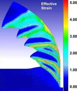
47 Plastic strain for rake angle (a) - 15 ο, (b)-5 ο, (c) 5 ο and (d) 15 ο Cutting speed and feed are 300 m/min and 0.05 mm/rev respectively, clearance angle is equal to 5 o and tool and workpiece material are CBN and AISI H-13 (55 HRC) tool steel, respectively. (a) (c) (b) (d) Precision Machining 47
48 (a) (a) (b) (b) Plastic strain rate and temperature for cutting edge radius (a) 0.01 mm and (b) 0.1 mm Precision Machining 48


49 The present case study pertains to the construction of a 2D orthogonal cutting, round tool edge model that can predict micromachining cutting forces as well as workpiece and tool temperatures when copper is machined with diamond tools. Precision Machining 49
50 The validation of the model is performed through comparison with results from papers with similar micromachining conditions. In order to determine the size effect in micromachining the specific cutting force is an appropriate characteristic. In the figures the specific cutting force for the three different depths of cut is depicted. For the specific cutting forces and for depth of cut lower that 10 μm the size effect can be observed. Precision Machining 50

51 Precision Machining 51
52 It should be noted that other precision machining processes, e.g. Electro-Discharge Machining (EDM), Water Jet Machining (WJM), Laser Machining (LM), Electro-Chemical Machining (ECM) etc., can be modelled with FEM. For every process, a different modeling strategy needs to be followed. Finite element method can treat all physical problems and with the right formulation, models for these processes can be constructed. Although this presentation is dedicated to finite elements, it would not be complete without reference to some other modeling techniques that are also used in precision machining. These include other numerical methods, e.g. the finite difference method (FDM), meshless methods, e.g. the element-free Galerkin (EFG) method and the smoothed particle hydrodynamics (SPH) method, soft computing modeling, e.g. Artificial Neural Networks (ANN) and a specialized method used for nanometric cutting, namely Molecular Dynamics. Precision Machining 52


53 MD is a modeling method in which atoms and molecules are interacting for a period of time, by means of a computer simulation. In order to simulate molecular systems, a very big number of particles is involved and a vast number of equations is produced to describe the properties of these systems; as a multidisciplinary method, laws and theories from mathematics, physics and chemistry consist the backbone of the method. In order to deal with these problems, numerical methods, rather than analytical ones, are used and algorithms from computer science and information theory are employed. Precision Machining 53


54 Precision Machining 54
STATUS OF FEM MODELING IN HIGH SPEED CUTTING - A Progress Report -
 STATUS OF FEM MODELING IN HIGH SPEED CUTTING - A Progress Report - Dr. Taylan Altan, Professor and Director Partchapol (Jay) Sartkulvanich, Graduate Research Associate Ibrahim Al-Zkeri, Graduate Research
Application of smooth-particle hydrodynamics in metal machining
 Loughborough University Institutional Repository Application of smooth-particle hydrodynamics in metal machining This item was submitted to Loughborough University's Institutional Repository by the/an
FINITE ELEMENT MODELLING OF BURR FORMATION IN METAL CUTTING 1. INTRODUCTION
 Journal of Machine Engineering, Vol. 14, No. 2, 2014 orthogonal cutting, burr, FEM simulation Pawel PRES 1 Waclaw SKOCZYNSKI 1 Marek STEMBALSKI 1 FINITE ELEMENT MODELLING OF BURR FORMATION IN METAL CUTTING
RESIDUAL STRESSES IN MACHINING USING FEM
 : Rev. Adv. A : Mater. Sci. 30 (2012) : : : : 267-272 : 267 RESIDUAL STRESSES IN MACHINING USING FEM A REVIEW C. Maranh o and J. P. Davim Department of Mechanical Engineering, University of Aveiro, Campus
FINITE ELEMENTSIMULATION IN ORTHOGONAL MACHINING OF INCONEL 718 ALLOY
 FINITE ELEMENTSIMULATION IN ORTHOGONAL MACHINING OF INCONEL 718 ALLOY P.DEEPAGANESH. ME CAD/CAM, Shanmuganathan Engineering College, Pudukottai. ABSTRACT Knowing the stringent operating conditions to which
CHAPTER 7 PREDICTION OF TEMPERATURE DISTRIBUTION ON CUTTING TOOL
 142 CHAPTER 7 PREDICTION OF TEMPERATURE DISTRIBUTION ON CUTTING TOOL The main objective of this chapter is to predict the temperature distribution on a turning tool by using the following methods: Build
FINITE ELEMENT MODELING OF RESIDUAL STRESSES OBTAINED BY CUTTING PIECES: A REVIEW
 International Journal of Modern Manufacturing Technologies ISSN 2067 3604, Vol. VI, No. 2 / 2014 FINITE ELEMENT MODELING OF RESIDUAL STRESSES OBTAINED BY CUTTING PIECES: A REVIEW Pavel Iurea Gheorghe Asachi
A REWIEV TO ADVANCED MODELING AND SIMULATION OF MACHINING PROCESS
 Kovač, P., Gostimirović, M., Sekulić, M., Savković B. A REWIEV TO ADVANCED MODELING AND SIMULATION OF MACHINING PROCESS Abstract: In the case of machining process, there are many phenomenon that are not
NUMERICAL MACHINING SIMULATION FOR AN AISI 304 STAINLESS STEEL CONSIDERING MICROFRACTURE MECHANICS ASPECTS
 Copyright 2013 by ABCM NUMERICAL MACHINING SIMULATION FOR AN AISI 304 STAINLESS STEEL CONSIDERING MICROFRACTURE MECHANICS ASPECTS Gil Magno Portal Chagas University of Sao Paulo USP Polytechnic School
A NEW ERA? 3M CUBITRON II REVEALS FULL POTENTIAL OF BEVEL-GEAR GRINDING
 A NEW ERA? 3M CUBITRON II REVEALS FULL POTENTIAL OF BEVEL-GEAR GRINDING Reinventing the world of grinding processes: 3M s geometrically defined sintered corundum technology, Cubitron II, meets the stringent
GRINDING AND OTHER ABRASIVE PROCESSES
 GRINDING AND OTHER ABRASIVE PROCESSES Grinding Related Abrasive Process Abrasive Machining Material removal by action of hard, abrasive particles usually in the form of a bonded wheel Generally used as
Deformation Criterion of Low Carbon Steel Subjected to High Speed Impacts
 Deformation Criterion of Low Carbon Steel Subjected to High Speed Impacts W. Visser, G. Plume, C-E. Rousseau, H. Ghonem 92 Upper College Road, Kingston, RI 02881 Department of Mechanical Engineering, University
PES INSTITUTE OF TECHNOLOGY BANGALORE SOUTH CAMPUS Hosur Road, (1K.M. Before Electronic City), Bangalore DEPARTMENT OF MECHANICAL ENGINEERING
, Bangalore DEPARTMENT OF MECHANICAL ENGINEERING") PES INSTITUTE OF TECHNOLOGY BANGALORE SOUTH CAMPUS Hosur Road, (1K.M. Before Electronic City), Bangalore 560 100 DEPARTMENT OF MECHANICAL ENGINEERING SOLUTION 3 rd INTERNAL TEST Subject : Machine Tools
PES INSTITUTE OF TECHNOLOGY BANGALORE SOUTH CAMPUS Hosur Road, (1K.M. Before Electronic City), Bangalore 560 100 DEPARTMENT OF MECHANICAL ENGINEERING SOLUTION 3 rd INTERNAL TEST Subject : Machine Tools
Cutting Data and Grinding. Dr Mirza Jahanzaib
 Cutting Data and Grinding Dr Mirza Jahanzaib Cutting Data TABLE 8.1 Data on orthogonal cutting of 4130 steel. TABLE 8.2 Data on orthogonal cutting of 9445 steel. Thrust force as a function of rake angle
INDEX. forging Axisymmetric isothermal forging, cabbaging, compression of cylinders,
 INDEX Accuracy of simulation, 333 Air bending, 21, 141-147 Air rounding, 21 ALPID program, 136 Analysis in metal forming, 26-52 closed-die forging, 34, 35-36, 37 cold extrusion, 39-41 cold forging, 39-41
FRAUNHOFER INSTITUTE FOR MACHINE TOOLS AND FORMING TECHNOLOGY IWU SIMULATION IN FORMING TECHNOLOGY
 FRAUNHOFER INSTITUTE FOR MACHINE TOOLS AND FORMING TECHNOLOGY IWU SIMULATION IN FORMING TECHNOLOGY 1 SIMULATION IN SHEET METAL FORMING Simulation is an essential part of the development chain, especially
Exit burr and break off analysis in micro grooving pyramid pattern
 Proceedings of the fourth International Symposium on Mechanics, Aerospace and Informatics Engineering 2009 Changwon Exhibition Convention Center (CECO), Korea, September 10 12, 2009 ISMAI04-EP-00 Exit
A Coupled Thermal and Mechanical Model of Sliding Wear
 9 th International LS-DYNA Users Conference Simulation Technology (4) A Coupled Thermal and Mechanical Model of Sliding Wear S. S. Akarca, W. J. Altenhof, and A. T. Alpas Department of Mechanical, Automotive,
NUMERICAL STUDY OF THE OCCURRENCE OF ADIABATIC SHEAR BANDING WITHOUT MATERIAL FAILURE. A Thesis by. Palanivel Swaminathan
 NUMERICAL STUDY OF THE OCCURRENCE OF ADIABATIC SHEAR BANDING WITHOUT MATERIAL FAILURE A Thesis by Palanivel Swaminathan Bachelors of Engineering, Anna University, India, 2006 Submitted to the Department
Manufacturing Technology I. Lecture 3. Fundamentals of Cutting
 Manufacturing Technology I Lecture 3 Fundamentals of Cutting Prof. Dr.-Ing. F. Klocke Structure of the lecture Examples: turning of steel The cutting part - Terms and symbols The cutting operation Loads
Modelling of Material Removal in Abrasive Flow Machining Process Using CFD Simulation
 Journal of Basic and Applied Engineering Research Print ISSN: 2350-0077; Online ISSN: 2350-0255; Volume 1, Number 2; October, 2014 pp. 73-78 Krishi Sanskriti Publications http://www.krishisanskriti.org/jbaer.html
CIRP Annals - Manufacturing Technology
 CIRP Annals - Manufacturing Technology 59 (2010) 77 82 Contents lists available at ScienceDirect CIRP Annals - Manufacturing Technology journal homepage: http://ees.elsevier.com/cirp/default.asp Investigations
THE SHAPE OF ABRASIVE GRAIN GENERATING METHODS IN NUMERICAL ANALYSIS 1. INTRODUCTION
 Journal of Machine Engineering, Vol. 12, No. 4, 2012 abrasive grain, modeling, Ansys/Ls-Dyna, surface layer Monika FORYSIEWICZ 1 Leon KUKIELKA 1 THE SHAPE OF ABRASIVE GRAIN GENERATING METHODS IN NUMERICAL
Fundamentals of Metal Forming
 Fundamentals of Metal Forming Chapter 15 15.1 Introduction Deformation processes have been designed to exploit the plasticity of engineering materials Plasticity is the ability of a material to flow as
The formation of oscillation marks in continuous casting of steel
 The formation of oscillation marks in continuous casting of steel 1 Introduction Continuous casting is a method of producing an infinite solid strand from liquid metal by continuously solidifying it as
where n is known as strain hardening exponent.
 5.1 Flow stress: Flow stress is the stress required to sustain a certain plastic strain on the material. Flow stress can be determined form simple uniaxial tensile test, homogeneous compression test, plane
136. Roller spinning forming regularity
 136. Roller spinning forming regularity Yang Pan 1, Li Xueguang 2, Chen Zhe 3, Yu Yang 4 College of Mechanical and Electric Engineering, Changchun University of Science and Technology, Changchun, 130022,
Influence of height and location of V-ring indenter on Void Volume Fraction variations during fine blanking process
 Tehran International Congress on Manufacturing Engineering (TICME2005) December 12-15, 2005, Tehran, Iran Influence of height and location of V-ring indenter on Void Volume Fraction variations during fine
Process Modeling in Impression-Die Forging Using Finite-Element Analysis
 CHAPTER 16 Process Modeling in Impression-Die Forging Using Finite-Element Analysis Manas Shirgaokar Gracious Ngaile Gangshu Shen 16.1 Introduction Development of finite-element (FE) process simulation
Advances in Engineering Research, volume 103 Proceedings of the 3rd International Conference on Material Engineering and Application (ICMEA 2016)
") Proceedings of the 3rd International Conference on Material Engineering and Application (ICMEA 2016) Modeling and Study of Fracture and Delamination in a Packaging Laminate De-Feng ZHANG 1,2, Md. Shafiqul
Proceedings of the 3rd International Conference on Material Engineering and Application (ICMEA 2016) Modeling and Study of Fracture and Delamination in a Packaging Laminate De-Feng ZHANG 1,2, Md. Shafiqul
Chapter 14: Metal-Forging Processes and Equipments
 Manufacturing Engineering Technology in SI Units, 6 th Edition Chapter 14: Metal-Forging Processes and Equipments Chapter Outline Introduction Open-die Forging Impression-die and Closed-die Forging Various
A STUDY OF FINE BLANKING PROCESS BY FEM SIMULATION. G. Fang, P. Zeng
 Key Engineering Materials Vols. 261-263 (2004) pp 603-608 Online available since 2004/Apr/15 at www.scientific.net (2004) Trans Tech Publications, Switzerland doi:10.4028/www.scientific.net/kem.261-263.603
ANALYSIS OF CUTTING FORCE AND CHIP MORPHOLOGY DURING HARD TURNING OF AISI D2 STEEL
 Journal of Engineering Science and Technology Vol. 10, No. 3 (2015) 282-290 School of Engineering, Taylor s University ANALYSIS OF CUTTING FORCE AND CHIP MORPHOLOGY DURING HARD TURNING OF AISI D2 STEEL
Determination of Optimal Cutting Conditions in Orthogonal Metal Cutting Using LS-DYNA with Design of Experiments Approach.
 8 th International LS-DYNA Users Conference Metal Forming (1) Determination of Optimal Cutting Conditions in Orthogonal Metal Cutting Using LS-DYNA with Design of Experiments Approach. David P. Masillamani
Chapter 8. Material-Removal
 4 4 6. 3 0 5 A M A N U F A C T U R I N G P R O C E S S E S Chapter 8. Material-Removal Processes: Cutting Sung-Hoon Ahn School of Mechanical and Aerospace Engineering Seoul National University Machining
NUMERICAL MODELLING OF HOT FORMING AND HEAT-TREATMENT OF ANNULAR GEARS
 Production Processes and Systems, Volume 5. No. 1. (2012) pp. 115-126. NUMERICAL MODELLING OF HOT FORMING AND HEAT-TREATMENT OF ANNULAR GEARS Prof. Dr. Miklós Tisza 1 Zsolt Lukács 2 Gaszton Gál 3 1 Professor,
Chapter 7. Finite Elements Model and Results
 Chapter 7 Finite Elements Model and Results 7.1 Introduction In this chapter, a three dimensional model was presented. The analytical model was developed by using the finite elements method to simulate
This is an electronic reprint of the original article. This reprint may differ from the original in pagination and typographic detail.
 Powered by TCPDF (www.tcpdf.org) This is an electronic reprint of the original article. This reprint may differ from the original in pagination and typographic detail. Laakso, Sampsa; Zhao, Tao; Agmell,
FEA Based Simulation and Experimental Analysis of Forces in Dry Milling of Inconel 718
 FEA Based Simulation and Experimental Analysis of Forces in Dry Milling of Inconel 718 N. Bauskar 1, R. Mali 2, T. Gupta 3* 1 PG Student, 2 Research Scholar, 3 Assistant Professor Visvesvaraya National
Fracture. Brittle vs. Ductile Fracture Ductile materials more plastic deformation and energy absorption (toughness) before fracture.
 before fracture.") 1- Fracture Fracture: Separation of a body into pieces due to stress, at temperatures below the melting point. Steps in fracture: 1-Crack formation 2-Crack propagation There are two modes of fracture depending
1- Fracture Fracture: Separation of a body into pieces due to stress, at temperatures below the melting point. Steps in fracture: 1-Crack formation 2-Crack propagation There are two modes of fracture depending
THEORY OF THERMO MECHANICAL PROCESSES IN WELDING
 THEORY OF THERMO MECHANICAL PROCESSES IN WELDING Theory of Thermomechanical Processes in Welding by Andrzej Sluzalec Technical University of Czestochowa. Poland ~ Springer A C.I.P. Catalogue record for
Theoretical study on Cold Open Die Forging Process Optimization for Multipass Workability
 Theoretical study on Cold Open Die Forging Process Optimization for Multipass Workability Ajitkumar Gaikwad 1-a, Shreyas Kirwai 1, Provat Koley 2, Dr. G. Balachandran 3 and Dr. Rajkumar Singh 1 1 Kalyani
Grinding force model for Inconel 718 with CBN and conventional wheels
 6th International Conference on Virtual Machining Process Technology (VMPT), Montréal, May 29th June 2nd, 2017 Grinding force model for Inconel 718 with CBN and conventional wheels H.Jamshidi, B.Yastıkcı,
Laser Assisted Machining of Hard-to-Wear Materials
 Laser Assisted Machining of Hard-to-Wear Materials by Kelly Armitage A/Prof. Syed Masood A/Prof. Milan Brandt Chalapi Pomat Weir Warman Ltd. Abstract This research is being conducted at the Industrial
CHAPTER 5 FINITE ELEMENT MODELING
 CHAPTER 5 FINITE ELEMENT MODELING 5.1 INTRODUCTION Masonry is a composite material with the building brick units and the mortar as the joining material, which are bonded together. Guinea [2000] 51 reported
Numerical study of nugget formation in resistance spot welding
 Numerical study of nugget formation in resistance spot welding M.Hamedi, H.Pashazadeh Abstract Resistance spot welding is a widely used joining process for fabricating sheet metal assemblies in automobile
We are IntechOpen, the world s leading publisher of Open Access books Built by scientists, for scientists. International authors and editors
 We are IntechOpen, the world s leading publisher of Open Access books Built by scientists, for scientists 3,900 116,000 120M Open access books available International authors and editors Downloads Our
ULTRAPRECISION MICROMACHINING OF MICROFLUIDIC DEVICES BY USE OF A HIGH-SPEED AIRBEARING SPINDLE
 ULTRAPRECISION MICROMACHINING OF MICROFLUIDIC DEVICES BY USE OF A HIGH-SPEED AIRBEARING SPINDLE Chunhe Zhang 1, Allen Y. Yi 1, Lei Li 1, L. James Lee 1, R. Ryan Vallance 2, Eric Marsh 3 1 The Ohio State
Polycrystalline cubic boron nitride blanks and cut shapes for milling and turning tools. TOOLMAKER SOLUTIONS BZN Compacts Tool Blanks and Inserts
 Polycrystalline cubic boron nitride blanks and cut shapes for milling and turning tools TOOLMAKER SOLUTIONS BZN Compacts Tool Blanks and Inserts BZN COMPACTS TOOL BLANKS AND INSERTS Hyperion manufactures
2D and 3D Simulation of Ductile Crack Propagation by Plastic Collapse of Micro-ligaments 1. Geralf Hütter*, Lutz Zybell, Uwe Mühlich and Meinhard Kuna
 2D and 3D Simulation of Ductile Crack Propagation by Plastic Collapse of Micro-ligaments 1 Geralf Hütter*, Lutz Zybell, Uwe Mühlich and Meinhard Kuna TU Bergakademie Freiberg, Institute of Mechanics and
Evaluation of the Minimum Quantity Lubrication in Orthogonal Cutting with the Application of Finite Element Method
 International Journal of Mechanical & Mechatronics Engineering IJMME-IJENS Vol:17 No:01 1 Evaluation of the Minimum Quantity Lubrication in Orthogonal Cutting with the Application of Finite Element Method
CHAPTER 7 ANALYTICAL PROGRAMME USING ABAQUS
 87 CHAPTER 7 ANALYTICAL PROGRAMME USING ABAQUS 7.1 GENERAL With the advances in modern computing techniques, finite element analysis has become a practical and powerful tool for engineering analysis and
COMPARISON BETWEEN NUMERICAL SIMULATIONS AND EXPERIMENTS FOR SINGLE POINT DIAMOND TURNING OF SILICON CARBIDE
 COMPARISON BETWEEN NUMERICAL SIMULATIONS AND EXPERIMENTS FOR SINGLE POINT DIAMOND TURNING OF SILICON CARBIDE John A. Patten, Jerry Jacob and Biswarup Bhattacharya Department of Manufacturing Engineering
CHAPTER 2: LITERATURE SURVEY
 7 CHAPTER 2: LITERATURE SURVEY 2.1. Introduction The powder metallurgy processing is one of the oldest and economic routes for producing critical and complex shaped products [1-3]. P/M is one of the most
MILD STEEL SHEET METAL FORMING USING ABAQUS SOFTWARE: INFLUENCE OF DRAWBEADS IN MINIMIZE SPRINGBACK
 MILD STEEL SHEET METAL FORMING USING ABAQUS SOFTWARE: INFLUENCE OF DRAWBEADS IN MINIMIZE SPRINGBACK Nor Assikin Khamis 1, Suziyani Md Zin 1 and Abdul Rahim Bahari 2 1 Department of Mechanical Engineering,
Finite Element Modeling for Prediction of Cutting Forces during Micro Turning of Titanium Alloy
 5 th International & 26 th All India Manufacturing Technology, Design and Research Conference (AIMTDR 2014) December 12 th 14 th, 2014, IIT Guwahati, Assam, India Finite Element Modeling for Prediction
IMPERFECTIONSFOR BENEFIT. Sub-topics. Point defects Linear defects dislocations Plastic deformation through dislocations motion Surface
 IMPERFECTIONSFOR BENEFIT Sub-topics 1 Point defects Linear defects dislocations Plastic deformation through dislocations motion Surface IDEAL STRENGTH Ideally, the strength of a material is the force necessary
Chapter 15 Fundamentals of Metal Forming. Materials Processing. Deformation Processes. MET Manufacturing Processes
 MET 33800 Manufacturing Processes Chapter 15 Fundamentals of Metal Forming Before you begin: Turn on the sound on your computer. There is audio to accompany this presentation. Materials Processing Chapters
PCD Grooving Tools, PCD Turning Tools, PCD Boring Tools for machining Pistons
 PCD Grooving Tools, PCD Turning Tools, PCD Boring Tools for machining Pistons Development Background of Automotive Engine Piston Global automotive piston market is expected to reach $15,705 million by
Analysis of plastic penetration in process of groove ball-section ring rolling
 Journal of Mechanical Science and Technology Journal of Mechanical Science and Technology 22 (2008) 1374~1382 www.springerlink.com/content/1738-494x Analysis of plastic penetration in process of groove
Thermal effects and friction in forming
 Thermal effects and friction in forming R. Chandramouli Associate Dean-Research SASTRA University, Thanjavur-613 401 Joint Initiative of IITs and IISc Funded by MHRD Page 1 of 10 Table of Contents 1.Thermal
An Overview of Effect of Punch Tool Wear Radius on Burr Formation In Sheet Metal Blanking
 International OPEN ACCESS Journal Of Modern Engineering Research (IJMER) An Overview of Effect of Punch Tool Wear Radius on Burr Formation In Sheet Metal Blanking Vaditake Sukhadeo Satoba 1, Shinde Vilas
CHAPTER 21. Cutting-Tool Materials and Cutting Fluids. Kalpakjian Schmid Manufacturing Engineering and Technology 2001 Prentice-Hall Page 21-1
 CHAPTER 21 Cutting-Tool Materials and Cutting Fluids Manufacturing Engineering and Technology 2001 Prentice-Hall Page 21-1 Cutting Tool Material Hardnesses Figure 21.1 The hardness of various cutting-tool
Computer Aided Modeling and Optimization of Crankshaft C.M.Balamurugan, R.Krishnaraj, Dr.M.Sakthivel, K.Kanthavel, Deepan Marudachalam M.G, R.
 International Journal of Scientific & Engineering Research Volume 2, Issue 8, August-2011 1 Computer Aided Modeling and Optimization of Crankshaft C.M.Balamurugan, R.Krishnaraj, Dr.M.Sakthivel, K.Kanthavel,
SANDVIK HYPERION BZN COMPACTS TOOL BLANKS AND INSERTS
 SANDVIK HYPERION BZN COMPACTS TOOL BLANKS AND INSERTS BZN COMPACTS TOOL BLANKS AND INSERTS Sandvik Hyperion manufactures a complete line of high quality polycrystalline CBN products for machining ferrous
Cutting Tool Materials and Cutting Fluids. Dr. Mohammad Abuhaiba
 Cutting Tool Materials and Cutting Fluids HomeWork #2 22.37 obtain data on the thermal properties of various commonly used cutting fluids. Identify those which are basically effective coolants and those
1379. Finite element analysis and experiments of saw chip formation for bearing steel GCr15 in hard cutting process
 1379. Finite element analysis and experiments of saw chip formation for bearing steel GCr15 in hard cutting process Guangjun Chen 1, Lingguo Kong 2, Xianli Liu 3 1, 2 College of Mechanical Engineering,
Investigation of Cutting temperature distribution during hard turning of AISI 4340: A numerical approach
 Investigation of Cutting temperature distribution during hard turning of AISI 4340: A numerical approach O. N. Bandal 1, O. Y. Ghodekar, S. S. Bhanage 3, P. M. Gorwadkar 3, A. P. Kulkarni 4, F A Shaikh
Numerical Modeling and Analysis of Unreinforced Masonry Walls
 Journal of Civil Engineering and Architecture 11 (2017) 870-878 doi: 10.17265/1934-7359/2017.09.006 D DAVID PUBLISHING Numerical Modeling and Analysis of Unreinforced Masonry Walls Isak Idrizi 1 and Zekirija
CHAPTER 7 FINITE ELEMENT ANALYSIS
 189 CHAPTER 7 FINITE ELEMENT ANALYSIS 7.1 SCOPE In Engineering applications, the physical response of the structure to the system of external forces is very much important. Understanding the response of
How to model Mohr-Coulomb interaction between elements in Abaqus
 How to model Mohr-Coulomb interaction between elements in Abaqus Problem description We want to model the interaction between two masonry walls and a timber beam. The elements are connected by special
Model based planning of complex micromanufacturing
 Model based planning of complex micromanufacturing strategies Daniel Zdebski, Shukri Afazov, Svetan Ratchev, Joel Segal Precision Manufacturing Centre, The University of Nottingham, University Park, Nottingham,
Available online at ScienceDirect. Procedia CIRP 31 (2015 ) th CIRP Conference on Modelling of Machining Operations
 th CIRP Conference on Modelling of Machining Operations") Available online at www.sciencedirect.com ScienceDirect Procedia CIRP 31 (2015 ) 24 28 15th CIRP Conference on Modelling of Machining Operations Springback in metal cutting with high cutting speeds N.
Available online at www.sciencedirect.com ScienceDirect Procedia CIRP 31 (2015 ) 24 28 15th CIRP Conference on Modelling of Machining Operations Springback in metal cutting with high cutting speeds N.
Effect of Cutting Parameters on Tool Life
 International Journal of Current Engineering and Technology E-ISSN 2277 4106, P-ISSN 2347 5161 2016 INPRESSCO, All Rights Reserved Available at http://inpressco.com/category/ijcet Research Article Sandip
Finite element analyses of TMCP steel plates with consideration of edge masking
 Available online at www.sciencedirect.com Procedia Engineering 00 (2013) 000 000 CTAM 2013 The 37 th National Conference on Theoretical and Applied Mechanics (37th-NCTAM) The 1 st International Conference
Effect of Isothermal Annealing Temperatures and Roller Burnishing on the Microhardness and Surface Quality of H13 Alloy Steel
 J. Appl. Res. Ind. Eng. Vol. 4, No. 3 (217) 25 214 Journal of Applied Research on Industrial Engineering www.journal-aprie.com Effect of Isothermal Annealing Temperatures and Roller Burnishing on the Microhardness
INSTRUCTION PROFESSOR K. KOMVOPOULOS. Mechanical Behavior of Engineering Materials (ME 108) (Undergraduate course, junior/senior level)
 (Undergraduate course, junior/senior level)") INSTRUCTION PROFESSOR K. KOMVOPOULOS. Mechanical Behavior of Engineering Materials (ME 108) (Undergraduate course, junior/senior level) Part I Microstructure and Deformation of Materials Alloying and Hardening
INSTRUCTION PROFESSOR K. KOMVOPOULOS. Mechanical Behavior of Engineering Materials (ME 108) (Undergraduate course, junior/senior level) Part I Microstructure and Deformation of Materials Alloying and Hardening
Available online at ScienceDirect. Procedia CIRP 13 (2014 ) On surface grind hardening induced residual stresses
 On surface grind hardening induced residual stresses") Available online at www.sciencedirect.com ScienceDirect Procedia CIRP 13 (2014 ) 264 269 2 nd CIRP Conference on Surface Integrity (CSI) On surface grind hardening induced residual stresses Konstantinos
Available online at www.sciencedirect.com ScienceDirect Procedia CIRP 13 (2014 ) 264 269 2 nd CIRP Conference on Surface Integrity (CSI) On surface grind hardening induced residual stresses Konstantinos
FE MODELLING OF WEAR MECHANISMS OF CF/PEEK COMPOSITES
 FE MODELLING OF WEAR MECHANISMS OF CF/PEEK COMPOSITES K. Váradi 1, T. Goda 1 and K. Friedrich 2 1 Institute of Machine Design, Budapest University of Technology and Economics, Műegyetem rkp. 3., H-1111
Identification of Tool Life and Wear Characteristics of HSS Tools Used in Turning of Ck45
 Identification of Tool Life and Wear Characteristics of HSS Tools Used in Turning of Ck45 B. Moetakef Imani, S.A. Hosseini 2 and A. Baghal Safa 3 Mechanical Engineering Department, Ferdowsi University,
International Journal of Mechanical Engineering and Applications
 International Journal of Mechanical Engineering and Applications 2016; 4(3): 109-114 http://www.sciencepublishinggroup.com/j/ijmea doi: 10.11648/j.ijmea.20160403.12 ISSN: 2330-023X (Print); ISSN: 2330-0248
CHAPTER 3 FINITE ELEMENT SIMULATION OF WELDING
 47 CHAPTER 3 FINITE ELEMENT SIMULATION OF WELDING 3.1 INTRODUCTION Though welding process has many distinct advantages over other joining processes, it suffers from some major disadvantages like the evolution
11.3 Polishing with Laser Radiation
 196 E. Willenborg 11.3 Polishing with Laser Radiation Edgar Willenborg The surface roughness of a part or product strongly influences its properties and functions. Among these can be counted abrasion and
Modeling Component Assembly of a Bearing Using Abaqus
 Modeling Component Assembly of a Bearing Using Abaqus Bisen Lin, Ph.D., P.E. and Michael W. Guillot, Ph.D., P.E. Stress Engineering Services, Inc. Abstract: Assembly process of a bearing considered in
EFFECT OF LOCAL PLASTIC STRETCH OM TOTAL FATIGUE LIFE EVALUATION
 EFFECT OF LOCAL PLASTIC STRETCH OM TOTAL FATIGUE LIFE EVALUATION Abstract G. S. Wang Aeronautics Division, The Swedish Defence Research Agency SE-17290 Stockholm, Sweden wgs@foi.se This paper shows that
Development of New Grade SUMIBORON BN7000 for Cast Iron and Ferrous Powder Metal Machining
 SPECIAL ISSUE Development of New SUMIBORON for Cast Iron and Ferrous Powder Metal Machining Yusuke Matsuda*, Katsumi OKaMura, shinya uesaka and tomohiro FuKaYa SUMIBORON P (polycrystalline cubic boron
Using finite element simulations to optimise metal machining
 Using finite element simulations to optimise metal machining The majority of metal-cutting operations involve the creation of chips from the workpiece. Prediction of chip form is important because chip
EFFECT OF EXTRUSION PARAMETERS AND DIE GEOMETRY ON THE PRODUCED BILLET QUALITY USING FINITE ELEMENT METHOD
 EFFECT OF EXTRUSION PARAMETERS AND DIE GEOMETRY ON THE PRODUCED BILLET QUALITY USING FINITE ELEMENT METHOD A.Ε. Lontos 1, F.A. Soukatzidis 2, D.A. Demosthenous 1, A.K. Baldoukas 2 1. Mechanical Engineering
MACHINES DESIGN SSC-JE STAFF SELECTION COMMISSION MECHANICAL ENGINEERING STUDY MATERIAL MACHINES DESIGN
 1 SSC-JE STAFF SELECTION COMMISSION MECHANICAL ENGINEERING STUDY MATERIAL C O N T E N T 2 1. MACHINE DESIGN 03-21 2. FLEXIBLE MECHANICAL ELEMENTS. 22-34 3. JOURNAL BEARINGS... 35-65 4. CLUTCH AND BRAKES.
Theoretical study on Cold Open Die Forging Process Optimization for Multipass Workability
 MATEC Web of Conferences 80, Theoretical study on Cold Open Die Forging Process Optimization for Multipass Workability Ajitkumar Gaikwad 1-a, Shreyas Kirwai 1, Provat Koley 2, Dr. G. Balachandran 3 and
Optimization of Process parameters in hot machining of Inconel 718 alloy using FEM
 Optimization of Process parameters in hot machining of Inconel 718 alloy using FEM A. Kiran Kumar 1 and Dr. P. Venkataramaiah 2 1 Assistant Professor, Department of Mechanical Engineering, GITAM, Hyderabad,
Development of SUMIBORON BN7500 for Ferrous Powder Metal Finishing
 INDUSTRIAL MATERIALS Development of SUMIBORON for Ferrous Powder Metal Finishing Yusuke MATSUDA*, Katsumi OKAMURA and Satoru KUKINO SUMIBORON tools are widely used in the cutting of hard-to-cut ferrous
Investigation of Surface Roughness and Flank Wear by CBN and PCBN Tools on Hard Cr-Mo Steel
 Investigation of Surface Roughness and Flank Wear by CBN and PCBN Tools on Hard Cr-Mo Steel S.Thamizhmanii* and S.Hasan Abstract Hard turning is the latest technology and is used to turn hard materials
FACULTY OF ENGINEERING DOCTORAL THESIS. Studies and research on thin-walled hydroformed blanks. - Abstract - Ph.D.H.C.Prof.eng. Octavian C.
 FACULTY OF ENGINEERING DOCTORAL THESIS Studies and research on thin-walled hydroformed blanks - Abstract - PhD. Advisor Ph.D.H.C.Prof.eng. Octavian C. BOLOGA Ph.D. Candidate eng. Radu VASILE - Sibiu, 2016
Laboratory of Applied Mechanics and Reliability: Research Activities
 Laboratory of Applied Mechanics and Reliability: Research Activities Experimental mechanics Static, cyclic & fatigue testing, uniaxial / biaxial test, climatic chamber (- 10 C to 250 C). Vibration testing
CHAPTER 3 IMPROVEMENT OF DYNAMIC CHARACTERISTICS OF CUTTING TOOL SYSTEM USING VISCOELASTIC DAMPER
 44 CHAPTER 3 IMPROVEMENT OF DYNAMIC CHARACTERISTICS OF CUTTING TOOL SYSTEM USING VISCOELASTIC DAMPER This chapter introduces a novel design for turning tool holder assembly with enhanced damping capability.
Thermal Analysis of Milling Cutter Using Finite Element Analysis Tool
 Thermal Analysis of Milling Cutter Using Finite Element Analysis Tool Meher R. Pratapwar 1, Neeraj P. Raut 2, Akash S. Rameshware 3, Pavan S. Manekar 4 1,2,3,4Student, Dept. of Mechanical Engineering,
Influence of particles-matrix interphase on stress distribution in particulate composite with polymer matrix
 Applied and Computational Mechanics 1 (2007) 143-148 Influence of particles-matrix interphase on stress distribution in particulate composite with polymer matrix Z. Majer a,b, *, P. Hutař a,, L. Náhlík
Possibility to Control Surface Integrity in Grinding
 Possibility to Control Surface Integrity in Grinding Bogdan Kruszyński, Technical University of Łódź, Łódź, Poland Shinichi Togo, Tohoku Gakuin University, Tagajo, Japan Ryszard Wójcik, Technical University
Manufacturing Processes 1 (MDP 114)
") Manufacturing Processes 1 (MDP 114) First Year, Mechanical Engineering Dept., Faculty of Engineering, Fayoum University Dr. Ahmed Salah Abou Taleb 1 Cutting-Tool Materials and Cutting Fluids 2 Fracture
Manufacturing Processes 1 (MDP 114) First Year, Mechanical Engineering Dept., Faculty of Engineering, Fayoum University Dr. Ahmed Salah Abou Taleb 1 Cutting-Tool Materials and Cutting Fluids 2 Fracture