Table of Contents. About Smalley Smalley Steel Ring Company... 4
|
|
|
- Walter White
- 6 years ago
- Views:
Transcription
1

2


3 Table of Contents About Smalley Smalley Steel Ring Company About Wave Springs General Spring Information/Comparitor Spring Applications Wave Springs From Stock Series Spring Type SSR Gap/Overlap Single Turn SSR-N Narrow Single Turn RW Wavo (Round Wire) Single Turn SSB Metric Bearing Pre-Load Single Turn Metric Bearing Cross Reference Chart C/CS Crest-to-Crest/Shim Ends CM/CMS Metric Crest-to-Crest SSRS Shim Spring Tester/Fatigue Tester About Retaining Rings General Ring Information Ring Selection Guide/Ring Interchange Listing Ring Applications Assembly/Removal Methods Internal Retaining Rings From Stock Series Rating, Ring Type VH Light Duty Single Turn, Spirolox WH Medium Duty -Turn, Spirolox WHW WaveRing, Spirolox WHT Medium Heavy Duty -Turn, Spirolox WHM Heavy Duty -Turn, Spirolox FHE Heavy Duty Single Turn, Constant Section VHM Metric Light Duty Single Turn, Spirolox EH Metric Aerospace, Spirolox DNH Metric DIN, Spirolox FH Metric DIN, Constant Section HH Hoopster XAH Constant Section XDH Constant Section External Retaining Rings From Stock Series Rating, Ring Type VS Light Duty Single Turn, Spirolox WS Medium Duty -Turn, Spirolox WSW WaveRing, Spirolox WST Medium Heavy Duty -Turn, Spirolox WSM Heavy Duty -Turn, Spirolox FSE Heavy Duty Single Turn, Constant Section VSM Metric Light Duty Single Turn, Spirolox ES Metric Aerospace, Spirolox DNS Metric DIN, Spirolox FS Metric DIN, Constant Section HS Hoopster XAS Constant Section XDS Constant Section Copyright 0 by Smalley Steel Ring Company Lake Zurich, IL 6007 All rights reserved The following are trademarks of Smalley Steel Ring Company: Gap-Type, No-Tooling-Costs, No-Tooling-Charges, Overlap-Type. The following are registered trademarks of Smalley Steel Ring Company: All Springs Are Not Equal, Circular-Grain, Crest-to-Crest, Edgewound- Coiled, No Ears to Interfere, Quick Ship, Smalley, Spirawave, Spirolox, WaveRing, Wavo, Hoopster. Laminar Seal Rings Engineering Special Designs Introduction to Smalley Engineering Materials / Finishes Spring Design Ring Design End Configurations Hoopster Design Smalley Website Spring Checklist Ring Checklist How to Order Glossary Sample Request Form

4 General Info Company Profile One thing has never changed and that is our commitment to providing ever-higher levels of quality, performance, deliverability, and value to our customers. Founded in 98 as a supplier of precision automotive piston rings, Smalley Steel Ring Company had many years of successful growth in an expanding marketplace. Having had a variety of products throughout the years, it wasn t until 96, when present ownership began the development of products in the wire forming industry. Spiral Retaining Rings and Wave Springs emerged and Smalley developed into a reputable manufacturer of precision rings, springs & wire forms. But one thing never changed from years back, and that is our commitment to providing ever-higher levels of quality, performance, deliverability, and value to our customers. Today, Smalley Steel Ring Company is a market leader in the industrial retaining ring and wave/compression spring business; a position we work hard to maintain and build upon. Every Smalley ring and spring is engineered and manufactured to the highest quality standards using skills and processes we have honed over three quarters of a century. Our obsession with quality, combined with our near-perfect record of on-time delivery, has earned us an approved supplier status with leading OEM manufacturers around the world. Due to the ceaseless demands we place upon ourselves, Smalley has won the coveted title of Preferred Source in the most demanding applications: automotive, agriculture, aerospace, electronics, appliance, industrial, medical and power generation. While we are understandably proud of the recognition we have received, ultimately, it is our products that set us apart. Unlike stamped rings and springs, which are die-stamped through the metal grain, our edgewound rings and springs have a circumferential metal grain structure that gives them exceptional strength, dimensional stability, and predictable performance characteristics. Finally, every Smalley ring and spring is backed by our continued support. We are constantly searching ways to expand and improve our Customer Service and Engineering/Technical Assistance. We welcome your comments and your design challenges. Engineers are available to help assist with any design questions. With regional offices in Europe, we are prepared to service our European customers. Smalley provides customized global supply chain solutions, to meet your WORLDWIDE manufacturing requirements, in Europe, Asia Pacific and the America s. Please call us at or visit our website today! No-Tooling-Charges For Specials

 and are free of burrs.")
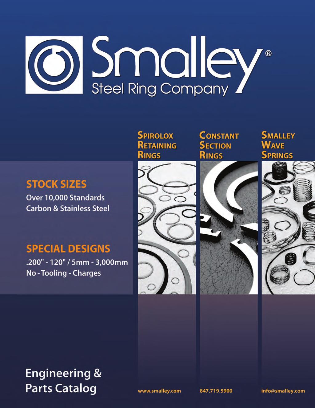
5 General Info Products All of Smalley s wave springs and retaining rings are manufactured with our unique edgewinding manufacturing process. This eliminates any tooling charges, greatly increases design flexibility and reduces lead times as dies do not have to be produced. Retaining Rings Unlike die-stamped circlips / retaining rings, Spirolox Retaining Rings and Constant Section Rings are coiled on edge to the exact diameter required. They have a uniform cross-section (or to use our terminology, No Ears To Interfere within an assembly) and are free of burrs. Spirolox Retaining Rings meet military and aerospace specifications and are found in thousands of mechanical products around the world. Wave Springs Wave springs are precise flat wire compression springs that fit into assemblies that other springs cannot. Since the overall lengths and operating heights of wave springs are lower than those of conventional round wire springs, they will often reduce the size of an assembly by as much as 50%. Of course, this will also reduce the part weight and raw material cost of every spring produced. Manufactured in USA Smalley

6 General Info Raw Material As we meet the increasing demand for more raw material sizes, the flat wire rolling mill operation in our plant continues to grow. Years ago, Smalley began a vertical integration that has evolved into the production of hundreds of material cross-sections in a wide variety of alloys. Our goal to supply Smalley customers with uncompromising quality and service. 6 No-Tooling-Charges For Specials

, effectively eliminating material waste.")

7 General Info Manufacturing Edgewinding, also known as The No-Tooling-Cost Process, is our precision forming operation that coils pre-tempered flat wire on edge to create a near-perfect circle. (Visualize a Slinky, the coiled metal toy which has delighted generations of children.) Circular-Grain metallurgy gives our products strength and stability far superior to that of conventional retaining rings and wave washers which are simply stamped through the metal grain. Smalley edgewound products can be coiled to your exact specification in any diameter and with any number of turns (layers or coils), effectively eliminating material waste. As flexible as it is precise, our edgewinding process accommodates your design changes without the need for additional tooling and die modifications. This facilitates your developmental work, allowing us to produce your low-quantity custom orders and your working prototypes quickly and economically. Even after your initial prototype is produced, or in mid-stream production, our edgewinding process allows us to alter your design or dimensions with simple machine adjustments or a change in raw material size. After the revised specifications are approved, we complete and document the final setup. Then, we quickly resume production of your order, whether it consists of one part or one million. Edgewinding Process Conventional Stamping Process Prototypes About the easiest way to test a theoretical design is to produce a working prototype a task at which Smalley excels. A prime example is the development of a custom wave spring. We can adjust dimensions, by changing the number of waves and the number of turns, and trying different combinations of spring variables. Finally, we test for function, before production, so we know we have it right. Smalley-produced prototypes are also the most economical way to provide results on a trial-and-error basis. From one to a thousand pieces, we can produce, try, modify, and reproduce your design as often as necessary all without special tooling costs. Wire Flattening Manufactured in USA Smalley

8 General Info Finished Parts Warehouse Smalley maintains a substantial parts inventory of every cataloged/ standard retaining ring and wave spring in both carbon and stainless steel. We do this to meet our JIT deliveries as well as any immediate requirement that you may have. In the rare circumstance that our inventory runs low, we can quickly replenish any item overnight. In addition to our finished parts, we house a vast inventory of raw material sizes, stocked in thousands of pounds of flat wire. We are always ready to meet your needs for a quick turnaround in low to high quantities of existing or new designs. Free Need a Sample? We offer free samples of any ring or spring found in our catalog. See page No-Tooling-Charges For Specials


9 General Info Customer Service Smalley is dedicated to giving you the most positive, efficient and economical service possible, each and every day. We continually train our staff on every important aspect of our business. We can split shipments to suit your just-in-time delivery requirements. We offer you lower prices for your annual higher-usage orders. Please contact us directly for complete details and ideas on how you can purchase economically. General Sales Information Description: The product descriptions in this catalog are intended to provide the user with practical information for application selection. Since it is not possible to include complete detail on all parts, please contact Smalley for any information not included in the description which may be critical for a specific application. Quotations: We will provide written or verbal quotations as requested. Returns: Parts not stocked which must be specially manufactured are not returnable except by special arrangement and will be subject to cancellation charges. Stocked parts may be returned for credit at a standard restocking charge (subject to condition). All returns of stocked parts must be made within 0 days from date of receipt of material. Delivery: Parts carried in stock normally will be shipped within 8 hours after receipt of an order. Special parts are normally delivered in weeks (if no special processes are required) or as previously arranged. Certifications: Standard Certificate of Conformance will be supplied at no charge. Material and other Certifications for plating, load, etc. will be furnished as quoted. Transportation: As specified by the customer. In the absence of instructions, the shipping method will be selected by us. Insurance will be provided only at the customer s request. Terms: /0/NET 0 on open accounts. For consideration of an open account, customers are requested to supply banking information and at least commercial credit references. Go to for Terms and Conditions, which apply. F.O.B.: Factory, Lake Zurich, Illinois, USA Packaging: Rings and springs 5 6" in diameter and under are bulk packaged. Rings and springs 8" and over in diameter are generally tube (coin) packaged in lengths 0 to 8 inches. Smalley is the proud recipient of the GM Supplier of the Year Award. Manufactured in USA Smalley

10 General Info Engineering & Design Assistance Smalley s engineering staff is always ready to address your application requirements. Usually, the sooner we are able to review what you need, the easier the solution will be. Please call us today. We invite you to draw upon our resources. Over the years, Smalley engineers have built an extensive library of over 5,000 applications while designing rings and springs in mechanical components and assemblies. In addition, we offer computeraided spring-design alternatives to meet your specifications. There are many more options that we would be pleased to review with you once your design criteria are established. We are ready to help you with the selection of a standard part from our vast inventory, or to modify a standard part to meet your exact needs. We are pleased to offer you additional step-by-step resources. The Special Designs section of this catalog will help you determine basic retaining ring and wave spring specifications. We also invite you to try the design section on our website for step-by-step interactive design guidelines and options. As you can see, we are well-equipped to help you develop the best design solution possible, just as we have for thousands of other companies in diverse industries. Specials At Smalley, specials are standard. It s easy to get a custom part from Smalley. With No-Tooling-Charges, die costs, or other fixture charges, we can manufacture a new ring or spring design in just two weeks or to meet your delivery schedules. Fast, precise, and economically that s how Smalley produces rings and springs, in short runs or high volumes. If you can t find a standard part to meet your needs from the wide selection in our catalog, please contact our engineering department for immediate assistance with your special design requirements. And please note: Smalley Rings and Springs are available from.00'' to 0'' in diameter. CAD Downloads Visit our website for CAD downloads in 90 different formats. It s easy to search and select a standard part for a quick upload to your computer. Quality Policy Smalley has established, and is continuously improving upon, a program that is designed to meet the following objectives: Total product conformance in terms of drawings, specifications and contractual requirements. 00% on-time delivery performance. Superior products with exceptional value. Prompt, professional and courteous response in every facet of design, manufacturing, sales, and customer service. Continued development and use of the latest technology. 0 No-Tooling-Charges For Specials
, quality assurance and customer satisfaction mean much more at Smalley.")
11 General Info Quality Assurance Smalley s Total Quality Management philosophy dictates our commitment to quality and customer satisfaction. While this commitment has earned us official certification (ISO 900, ISO/TS 699, AS 900 and ISO 00), quality assurance and customer satisfaction mean much more at Smalley. They are tradition; the very foundation upon which we have built our company. From the beginning, we have never lost sight of our goal: to supply Smalley customers with uncompromising quality and service. Smalley is committed to a quality policy that requires conformance to specification with controlled lot variation about the target, statistical quality control, defect prevention, and annual improvement in process and product. This is a companywide commitment involving every Smalley employee. Each person works towards excellence, individually and cooperatively, to provide superior products and services. A history of quality and strict compliance with military and aerospace standards has earned Smalley an approved supplier status with many leading original equipment manufacturers worldwide. Smalley has worked diligently to become their Preferred Source for spiral retaining rings and wave springs. In accordance with the requirements of ISO 900, ISO/TS 699, AS 900 and ISO 00, we have established and are continuously improving our quality systems. Use of the latest technology, including statistical tools, has helped us achieve and maintain the world-class quality associated with the Smalley name for more than 0 years. Smalley uses statistical quality control tools to assure the capability and stability of our coiling process. To begin with, we identify common dimensions to monitor and special causes of variation in the product. Then, we collect and analyze data on these critical dimensions. We perform disciplined sampling and take measurements during in-line and final inspection, and yet again, during pre-shipping inspection. We make formal SQC in-house training programs mandatory for many Smalley employees involved with manufacturing. This training has noticeably developed quality awareness and responsibility at all levels. Our employees have a clear understanding of what is expected, a means of regulating their processes and checking their output, and statistical tools to determine when machine adjustments are required. Smalley s machine capability studies help us identify sources of variation before they become a problem. We analyze the capabilities of all production machinery in primary and secondary operations, heat treating, and finishing. In addition, we follow our own meticulous procedures to determine the reproducibility and repeatability of our gauging systems. Due to the careful documentation of our quality, many Smalley customers have found that they can reduce or even eliminate their incoming inspections of our product. Many of our accounts have also revised their policy of dual sourcing and confidently rely on Smalley as their single source of Spirolox Retaining Rings, wave springs, constant section rings, expanders and other wire forms. Defect prevention, or near-zero defects, is a key goal at Smalley. We use the latest automated inspection techniques to monitor production. As a result, we are constantly studying the causes of variation, improving upon and developing processes with capability indexes (Cpk) exceeding.. Continuous improvement is an integral part of Smalley s quality plan. We require each of our departments to design and implement projects to improve their respective systems. Manufactured in USA Smalley

12 Wave Spring Introduction All Springs Are Not Equal Smalley Wave Springs offer the unique advantage of space savings when used to replace coil springs. By reducing spring operating height, wave springs also produce a decrease in the spring cavity. With a smaller assembly size and less material used in the manufacturing process, a cost savings is realized. Wave springs operate as load bearing devices. They take up play and compensate for dimensional variations within assemblies. A virtually unlimited range of forces can be produced whereby loads build either gradually or abruptly to reach a predetermined working height. This establishes a precise spring rate in which load is proportional to deflection. Functional requirements are necessary for both dynamic and static spring applications. Special performance characteristics are individually built into each spring to satisfy a variety of precise operating conditions. Typically, a wave spring will occupy an extremely small area for the amount of work it performs. The use of this product is demanded, but not limited to tight axial and radial space constraints. Product Performance With their smooth, circular coiled sinusoidal wave form, and rolled round edges of pre-tempered raw material, Smalley s edgewound Wave Springs offer many advantages over die stamped products. Loads and spring rates are more accurate, more predictable, and may be toleranced better than 50 percent tighter than stampings. The force of a Smalley Wave Spring will increase at a uniform rate throughout most of its available deflection. By any criteria, Smalley Wave Springs offer their users higher dependability and better performance. Since they are produced from full hard, pre-tempered raw material, there is no risk of distorting the spring during a hardening heat treatment. By contrast, subsequent manufacturing procedures for stamped wavy washers can lead to problems such as fatigue cracking and inaccurate or inconsistent loading between springs. All told, the metallurgy, the mechanical properties and the uniform dimensional stability of the Smalley edgewound Wave Spring provide a component for precision quality applications. SMALLEY WAVE SPRING COIL SPRING No-Tooling-Charges For Specials


13 Wave Spring Introduction Wave Spring Types Gap Type Wave Spring Overlap Type Wave Spring Gap & Overlap Type Conventional Gap and Overlap Type Wave Springs are used in a wide variety of applications. For short deflections and low-medium forces, they function with precision and dependability. These two types of Smalley Wave Springs permit radial expansion or growth in diameter within a cavity, without the binding or hang-up normally associated with die stamped wave washers. Just as their terms imply, the gap type is split to retain a gap between the ends, while the overlap type has overlapping ends. Thus, the ends are free to move circumferentially as the spring outside diameter grows during compression. For example, the O.D. of a Gap Type Wave Spring would fit.00 loose per side in a bore. Its I.D. clears a shaft by.00 per side. As the spring is deflected, the O.D. and I.D. grow larger until the O.D. contacts the bore. Continued deflection causes the gap ends to move closer together while the O.D. presses against the bore. An Overlap Type Wave Spring permits this type of cycling action in a similar manner. Crest-to-Crest Crest-to-Crest Wave Springs are prestacked in series, decreasing the spring rate proportionally to the number of turns. Uses are typically applications requiring low-medium spring rates and large deflections with low-medium forces. Among major advantages, this design eliminates the need to keep the wave crests aligned. The need to use a key locating device, or to insert a shim between individual springs is not necessary. Because the spring is integrally formed, the wave peaks hold their configuration. As a replacement for helical compression springs, Crest-to-Crest springs can develop similar forces, yet occupy one-half (½) or less the axial space. This allows for strict space constraints. Crest-to-Crest Wave Springs will maintain the same force and load specifications of a conventional round wire spring, but with the advantages of resultant lowered and compacted operating heights, free heights, and solid heights. continued Manufactured in USA Smalley


14 Wave Spring Introduction Wave Spring Types (cont d) Crest-to-Crest with Optional Shim Ends Crest-to-Crest Wave Springs are also available with squared-shim ends. Shim ends provide a 60 contact surface when compared to the wave point contact of plain ends. The shim-ends, under load, more evenly distribute the spring s force upon adjacent components. This feature is similar to the concept of double-disc grinding springs for a flat surface. Shim ends have also been used to affix springs to mating components, as a flat locating surface that may be attached by various methods in the assembly. Nested Nested Wave Springs are pre-stacked in parallel from one continuous filament of flat wire. The need to stack individual springs for higher loads is no longer necessary. Nested springs result in a spring rate that increases proportionally to the number of turns. They can exert tremendous forces, yet maintain the precision of a circular-grain wave spring. In many applications, Nested Wave Springs replace Belleville Springs, particularly in cases where a high but accurate force is needed. WAVO Wavo Springs are produced from round-section wire to provide higher loads while maintaining the accurate loading found in wave springs. As an alternative to Belleville Springs, the Wavo provides similar loads but with an accurate, predictable spring rate. Linear Expanders Linear expanders are a continuous wave formed (marcelled) wire length produce from spring tempered materials. They act as a load bearing device having approximately the same load/deflection characteristics as a wave spring. Forces act axially or radially depending on the installed position. Axial pressure is obtained by laying the expander flat in a straight line. Circular wrapping the expander produces a radial force or outward pressure. Linear expanders are available cut to length or as a continuous coil, for the user to cut as needed. No-Tooling-Charges For Specials


15 Wave Spring Applications B. Face Seal A. Pressure Relief Valve C. Clutch Drive D. Bayonet Connector E. Multi-Tooth Cutter A. Pressure Relief Valve An exact load applied to the top sealing plate was accomplished using a flat wire wave spring. Air pressure entering the top slots forces the plate away from the sealing surface providing the pressure relief mechanism. B. Face Seal Wave Spring applies pressure, to precisely load the carbon face against a mating surface, to properly seal fluids. The spring operates over a fixed working range and provides an exact force, unlike the stamped wavy washer it replaced which could not maintain the necessary spring rate. C. Clutch Drive Pressure on the round belt is produced by compressing the Wavo Spring through the sheave halves. The top threaded cap rotates to adjust the Wavo compression. The Wavo can produce a high force in a tight radial cavity. D. Bayonet Connector Overlap Type Wave Spring installed in an electronic connector assembly. As male and female components are rotated together into final assembly, the wave spring is compressed to its working height. In this position it exerts a constant force that locks both components together. E. Multi-Tooth Cutter A custom designed wave spring with locating tabs is contained in the housing. The spring applies a precise force to the two cutter halves, allowing them to oscillate but not rattle. Manufactured in USA Smalley


16 Wave Spring Applications F. Slip Clutch G. Bearing Pre-Load H. Flow Valve J. Sprinkler Valve I. Low Voltage Connector F. Slip Clutch Clutch drives when the V"- detents are in the V -slots. A Smalley Wave Spring maintains pressure to hold this position. As torque is in creased, the V -detents will ride up and out the V -slots, depressing the wave spring and developing the slip mechanism. When torque is decreased, the wave spring forces the V -detents firmly into the V -slots to drive again. G. Bearing Pre-Load One of the most common wave spring applications world-wide is a bearing preload arrangement as illustrated. Having the proper load will often extend bearing life by lowering operating temperatures, reducing vibration, minimizing wear and providing for quieter and smoother performance. H. Flow Valve As fluid pressure increases the Crest-to-Crest Wave Spring precisely controls the linear displacement of the piston, which positions the orifice for proper fluid flow. Because of the space savings of the Crestto-Crest design, the valve can be made smaller. I. Low Voltage Connector A Bayonet Connector couples as the male end rotates and follows the groove contour in the female end. A -Turn Nested Spirawave Wave Spring provides the pre-load between the two halves. A - Turn Nested Spring was necessary to develop a higher load in very tight radial and axial space. J. Sprinkler Valve With height restrictions accounted for, the Smalley Crest-to-Crest Wave Spring maintains constant pressure on the pop-up head, holding it firmly closed. In operation, water pressure releases the head by overcoming the spring s force. 6 No-Tooling-Charges For Specials


 to the tapered roller bearings.")


17 Wave Spring Applications K. Oil Valve L. High Speed Pump M. Quick Disconnect N. Vibration Isolator O. Floating Gear K. Oil Valve The force provided by the Crest-to-Crest Wave Spring in this oil valve application precisely regulates the amount of oil that is released. The Crest-to-Crest spring provides accurate resistance in a small space, allowing the overall size of the valve to be greatly reduced. L. High Speed Pump A Smalley Wavo Spring was specified to provide a higher preload (the force needed was greater than offered with a stock Wave Spring) to the tapered roller bearings. Also, the entire bearing/spindle arrangement is held in its housing by a spiral retaining ring. M. Quick Disconnect The sliding member of the disconnect is held in its forward/ locked position against the retaining ring, by the Crestto-Crest Spring. As the user slides the member in the opposite direction compressing the spring, the detent balls align with a groove and release. N. Vibration Isolator Wavo Springs provide high force and a relatively large axial displacement, in limited space. The springs are arranged in series for additional travel. O. Floating Gear Functioning in a contained bracket, a Crest-to-Crest Wave Spring loads a gear with light force allowing axial movement. The gear shown self-aligns with its mating gear during operation. Manufactured in USA Smalley
18 SSR Series Standard Section Springs Stock Items in carbon steel and 7-7 PH/C stainless steel. Springs listed below are wave, Overlap Type. Smalley Part Operates in Clears Shaft Load Work Free Number Radial Spring Number, Bore Diameter Diameter (lb) Height Height of Waves Thickness Wall Rate SSR SSR SSR SSR SSR SSR SSR SSR SSR SSR Add suffix -S7 for 7-7 stainless steel. Reference dimension. Theoretical dimension; measured in lb/in. See pages 6-7 for How to Order. OVERLAP TYPE SSR-0050 to SSR-06 Product Dimensions All dimensions in inches unless otherwise specified. WAVE RADIAL WALL THICKNESS FREE HEIGHT Bayonet Connector CLEARS SHAFT OPERATES IN BORE LOAD AT WORK HEIGHT 8 No-Tooling-Charges For Specials
19 SSR Series Stock Items in carbon steel and 7-7 PH/C stainless steel. Springs listed below are waves and up, Gap Type. Smalley Part Operates in Clears Shaft Load Work Free Number Radial Spring Number, Bore Diameter Diameter (lb) Height Height of Waves Thickness Wall Rate SSR SSR SSR SSR SSR SSR SSR SSR SSR SSR SSR SSR SSR SSR SSR SSR SSR SSR SSR SSR SSR SSR SSR SSR SSR SSR SSR SSR SSR SSR SSR SSR SSR SSR SSR SSR SSR SSR SSR SSR SSR SSR SSR SSR SSR SSR SSR SSR SSR ,000 SSR ,690 SSR ,9 SSR ,06 SSR SSR SSR SSR SSR SSR SSR ,86 SSR ,8 SSR ,86 SSR ,55 SSR ,8 GAP TYPE SSR-075 to SSR-600 Product Dimensions All dimensions in inches unless otherwise specified. THICKNESS MULTI-WAVE (SEE TABLE) CLEARS SHAFT OPERATES IN BORE RADIAL WALL FREE HEIGHT LOAD AT WORK HEIGHT Add suffix -S7 for 7-7 stainless steel. Reference dimension. Theoretical dimension; measured in lb/in. See pages 6-7 for How to Order. Manufactured in USA Smalley

20 SSR-N Series Narrow Section Wave Springs Smalley narrow section wave springs were originally designed to pre-load packings in telescoping hydraulic cylinders. They have also found other applications where working space is highly limited. This Smalley Wave Spring series is designed to fit into a bore with a light snap to assure perfect concentricity between the wave spring and assembly. When these narrow section wave springs are compressed, radial expansion is taken up by the gap in the spring to eliminate binding. Stock Items in carbon steel and 7-7 PH/C stainless steel. Springs listed below are waves and up, Gap Type. GAP TYPE SSR-05-N to SSR-0775-N Product Dimensions All dimensions in inches unless otherwise specified. MULTI-WAVE (SEE TABLE) RADIAL WALL Smalley Part Operates in Clears Shaft Load Work Free Number Radial Spring Number, Bore Diameter Diameter (lb) Height Height of Waves Thickness Wall Rate SSR-05-N SSR-07-N SSR-050-N SSR-06-N SSR-075-N SSR-087-N SSR-000-N SSR-0-N SSR-05-N SSR-07-N SSR-050-N SSR-06-N SSR-075-N SSR-087-N SSR-0500-N SSR-05-N SSR-055-N SSR-057-N SSR-0550-N SSR-056-N SSR-0575-N SSR-0587-N SSR-0600-N SSR-06-N SSR-065-N SSR-067-N SSR-0650-N SSR-0675-N SSR-0700-N SSR-075-N SSR-0750-N SSR-0775-N Add suffix -S7 for 7-7 stainless steel. Reference dimension. Theoretical dimension; measured in lb/in. See pages 6-7 for How to Order. THICKNESS FREE HEIGHT CLEARS SHAFT OPERATES IN BORE LOAD AT WORK HEIGHT 0 No-Tooling-Charges For Specials
 Height Height of Waves Diameter Rate RW-0050.500.08 5.05.06.0,500 RW-006.65.57 50.06.077.")
21 WAVO Series Stock Items in carbon and 7-7 PH/C stainless steel. Smalley Part Operates in Clears Shaft Load Work Free Number Wire Spring Number, Bore Diameter Diameter (lb) Height Height of Waves Diameter Rate RW ,500 RW ,86 RW ,75 RW , RW ,86 RW ,000 RW ,99 RW ,65 RW ,000 RW ,85 RW ,89 RW , RW ,6 RW ,55 RW ,98 RW ,05 RW , RW ,00 RW ,966 RW ,65 RW ,579 RW ,500 RW ,97 RW ,89 RW ,7 RW ,667 RW ,79 RW , RW ,000 RW ,8 RW ,0 RW ,60 RW ,000 RW ,50 RW ,597 RW ,5 RW ,57 RW ,05 RW ,67 RW , RW ,79 RW ,000 RW ,77 RW ,077 RW ,9 Product Dimensions All dimensions in inches unless otherwise specified. WIRE MULTI-WAVE (SEE TABLE) Add suffix -S7 for 7-7 stainless steel. Reference dimension. Theoretical dimension; measured in lb/in. See pages 6-7 for How to Order. CLEARS SHAFT OPERATES IN BORE LOAD AT WORK HEIGHT FREE HEIGHT Manufactured in USA Smalley

22 SSB Series Metric Bearing Preload Springs Smalley Circular-Grain bearing preload Wave Springs eliminate play and minimize bearing noise. The constant light/medium pressure they apply removes play between the ball bearings and the bearings inner and outer races. Preloading can reduce the possibility of bearing damage due to vibration (vibratory loading) and wear due to repetitive and non-repetitive runout. Stock Items in carbon steel and 7-7 PH/C stainless steel. Springs listed below are and waves Overlap Type. OVERLAP TYPE SSB-006 to SSB-07 Product Dimensions All dimensions in millimeters unless otherwise specified. WAVE SPRING FITS SNUG IN HOUSING Smalley Part Bearing O.D. Clears Shaft Load Work Free Number Radial Spring Number, 5 (mm) Diameter (N) Height Height of Waves Thickness Wall Rate SSB SSB SSB SSB SSB SSB SSB SSB SSB SSB SSB SSB SSB SSB SSB SSB SSB SSB SSB SSB SSB SSB SSB SSB Add suffix -S7 for 7-7 stainless steel. Wave springs fit snug in housing. Reference dimension. Theoretical dimension; measured in N/mm. 5 See pages 6-7 for How to Order. MULTI-WAVE (SEE TABLE) THICKNESS RADIAL WALL FREE HEIGHT Bearing Assembly BEARING O.D. LOAD AT WORK HEIGHT No-Tooling-Charges For Specials
23 SSB Series Stock Items in carbon steel and 7-7 PH/C stainless steel. Springs listed below are 5 waves and up, Gap Type. Smalley Part Bearing O.D. Clears Shaft Load Work Free Number Radial Spring Number, 5 (mm) Diameter (N) Height Height of Waves Thickness Wall Rate SSB SSB SSB SSB SSB SSB SSB SSB SSB SSB SSB SSB SSB SSB SSB SSB SSB SSB SSB SSB SSB SSB SSB SSB SSB SSB SSB SSB SSB SSB SSB SSB SSB SSB SSB SSB SSB SSB SSB SSB SSB SSB SSB SSB SSB SSB SSB SSB SSB SSB SSB SSB GAP TYPE SSB-09 to SSB-8 Product Dimensions All dimensions in millimeters unless otherwise specified. MULTI-WAVE (SEE TABLE) WAVE SPRING FITS SNUG IN HOUSING RADIAL WALL Add suffix -S7 for 7-7 stainless steel. Wave springs fit snug in housing. Reference dimension. Theoretical dimension; measured in N/mm. 5 See pages 6-7 for How to Order. THICKNESS FREE HEIGHT BEARING O.D. LOAD AT WORK HEIGHT Manufactured in USA Smalley
24 Cross Reference Guide SSB Bearing Table Use this cross-reference guide to select the appropriate Wave Spring for your bearing size. The numbers represent typical standard bearing part numbers and/or the suffix of a standard bearing size. Stock Items in carbon steel and 7-7 PH/C stainless steel. Bearing Part Numbers Smalley Part Bearing Extra Extremely Extra Number, O.D. (mm) Small Light Light Narrow Light Medium Heavy SSB SSB , 6 SSB , 8 00 SSB KV 0 SSB SSB SSB SSB SSB SSB SSB SSB SSB SSB SSB SSB SSB SSB SSB SSB SSB SSB SSB SSB SSB SSB SSB SSB SSB SSB SSB SSB SSB SSB SSB SSB SSB SSB SSB SSB SSB SSB SSB SSB SSB SSB Add suffix -S7 for 7-7 stainless steel. Wave springs fit snug in housing. Check bearing dimensions. See pages 6-7 for How to Order. No-Tooling-Charges For Specials
25 Cross Reference Guide Use this cross-reference guide to select the appropriate Wave Spring for your bearing size. The numbers represent typical standard bearing part numbers and/or the suffix of a standard bearing size. Stock Items in carbon steel and 7-7 PH/C stainless steel. Bearing Part Numbers Smalley Part Bearing Extra Extremely Extra Number, O.D. (mm) Small Light Light Narrow Light Medium Heavy SSB SSB SSB SSB SSB SSB SSB SSB SSB SSB SSB SSB SSB SSB SSB SSB SSB SSB SSB SSB SSB SSB SSB SSB SSB SSB SSB SSB SSB SSB Add suffix -S7 for 7-7 stainless steel. Wave springs fit snug in housing. Check bearing dimensions. See pages 6-7 for How to Order. Manufactured in USA Smalley
26 C/CS Series Crest-To-Crest Springs Stock Items in carbon steel and 7-7 PH/C stainless steel. Product Dimensions OPERATES IN BORE FREE HEIGHT LOAD AT WORK HEIGHT FREE HEIGHT All dimensions in inches unless otherwise specified. LOAD AT WORK HEIGHT CLEARS SHAFT Plain Ends Shim Ends Order Options C 07-L RADIAL WALL MULTI-WAVE (SEE TABLE) WIRE THICKNESS WIRE THICKNESS TURNS MULTI-WAVE (SEE TABLE) TURNS End options: Plain ends C Squared-shim ends CS Material option: Carbon Steel (blank) Stainless Steel S7 Operates Clears Number Number Smalley Part in Bore Shaft Load Work Free of of Radial Spring Number,, 5 Diameter Diameter (lb) Height Height Waves Turns Thickness Wall Rate C05-L* C05-L* C05-L* C05-L* C05-L5* C05-L6* C05-L7* C05-L8* C05-L9* C05-M* C05-M* C05-M* C05-M* C05-M5* C05-M6* C05-M7* C05-M8* C05-M9* C0-L C0-L C0-L C0-L C0-L C0-L C0-L C0-L C0-L C0-M C0-M C0-M C0-M C0-M C0-M C0-M C0-M C0-M C07-L C07-L C07-L C07-L C07-L C07-L C07-L C07-L C07-L C07-M C07-M C07-M C07-M C07-M C07-M C07-M C07-M C07-M Use C prefix for plain ends. Use CS prefix for squared-shim ends. Add suffix -S7 for 7-7 stainless steel. Reference dimension. Theoretical dimension; measured in lb/in. 5 See See pages 6-7 for How to Order. *Not available with shim ends 6 No-Tooling-Charges For Specials
27 C/CS Series Stock Items in carbon steel and 7-7 PH/C stainless steel. Operates Clears Number Number Smalley Part in Bore Shaft Load Work Free of of Radial Spring Number,, 5 Diameter Diameter (lb) Height Height Waves Turns Thickness Wall Rate C0-L C0-L C0-L C0-L C0-L C0-L C0-L C0-L C0-L C0-M C0-M C0-M C0-M C0-M C0-M C0-M C0-M C0-M C050-L C050-L C050-L C050-L C050-L C050-L C050-L C050-L C050-L C050-M C050-M C050-M C050-M C050-M C050-M C050-M C050-M C050-M C050-H C050-H C050-H C050-H C050-H C050-H C050-H C050-H C050-H C056-L C056-L C056-L C056-L C056-L C056-L C056-L C056-L C056-L Use C prefix for plain ends. Use CS prefix for squared-shim ends. Add suffix -S7 for 7-7 stainless steel. Reference dimension. Theoretical dimension; measured in lb/in. 5 See pages 6-7 for How to Order. Product Dimensions OPERATES IN BORE FREE HEIGHT LOAD AT WORK HEIGHT FREE HEIGHT All dimensions in inches unless otherwise specified. LOAD AT WORK HEIGHT CLEARS SHAFT Plain Ends Shim Ends Order Options C 07-L RADIAL WALL MULTI-WAVE (SEE TABLE) WIRE THICKNESS WIRE THICKNESS TURNS MULTI-WAVE (SEE TABLE) TURNS End options: Plain ends C Squared-shim ends CS Material option: Carbon Steel (blank) Stainless Steel S7 Manufactured in USA Smalley
28 C/CS Series Crest-To-Crest Springs Stock Items in carbon steel and 7-7 PH/C stainless steel. Product Dimensions OPERATES IN BORE FREE HEIGHT LOAD AT WORK HEIGHT FREE HEIGHT All dimensions in inches unless otherwise specified. LOAD AT WORK HEIGHT CLEARS SHAFT Plain Ends Shim Ends Order Options C 07-L RADIAL WALL MULTI-WAVE (SEE TABLE) WIRE THICKNESS WIRE THICKNESS TURNS MULTI-WAVE (SEE TABLE) TURNS End options: Plain ends C Squared-shim ends CS Material option: Carbon Steel (blank) Stainless Steel S7 Operates Clears Number Number Smalley Part in Bore Shaft Load Work Free of of Radial Spring Number,, 5 Diameter Diameter (lb) Height Height Waves Turns Thickness Wall Rate C056-M C056-M C056-M C056-M C056-M C056-M C056-M C056-M C056-M C056-H C056-H C056-H C056-H C056-H C056-H C056-H C056-H C056-H C06-L C06-L C06-L C06-L C06-L C06-L C06-L C06-L C06-M C06-M C06-M C06-M C06-M C06-M C06-M C06-M C06-H C06-H C06-H C06-H C06-H C06-H C06-H C06-H C075-L C075-L C075-L C075-L C075-L C075-L C075-L C075-M C075-M C075-M C075-M C075-M C075-M C075-M C075-H C075-H C075-H C075-H C075-H C075-H C075-H Use C prefix for plain ends. Use CS prefix for squared-shim ends. Add suffix -S7 for 7-7 stainless steel. Reference dimension. Theoretical dimension; measured in lb/in. 5 See pages 6-7 for How to Order. 8 No-Tooling-Charges For Specials
29 C/CS Series Stock Items in carbon steel and 7-7 PH/C stainless steel. Operates Clears Number Number Smalley Part in Bore Shaft Load Work Free of of Radial Spring Number,, 5 Diameter Diameter (lb) Height Height Waves Turns Thickness Wall Rate C087-L C087-L C087-L C087-L C087-L C087-L C087-L C087-M C087-M C087-M C087-M C087-M C087-M C087-M C087-H C087-H C087-H C087-H C087-H C087-H C087-H C00-L C00-L C00-L C00-L C00-L C00-L C00-L C00-L C00-L C00-L C00-L C00-M C00-M C00-M C00-M C00-M C00-M C00-M C00-M C00-M C00-M C00-M C00-H C00-H C00-H C00-H C00-H C00-H C00-H C00-H C00-H C00-H C00-H Use C prefix for plain ends. Use CS prefix for squared-shim ends. Add suffix -S7 for 7-7 stainless steel. Reference dimension. Theoretical dimension; measured in lb/in. 5 See pages 6-7 for How to Order. Product Dimensions OPERATES IN BORE FREE HEIGHT LOAD AT WORK HEIGHT FREE HEIGHT All dimensions in inches unless otherwise specified. LOAD AT WORK HEIGHT CLEARS SHAFT Plain Ends Shim Ends Order Options C 07-L RADIAL WALL MULTI-WAVE (SEE TABLE) WIRE THICKNESS WIRE THICKNESS TURNS MULTI-WAVE (SEE TABLE) TURNS End options: Plain ends C Squared-shim ends CS Material option: Carbon Steel (blank) Stainless Steel S7 Manufactured in USA Smalley
30 C/CS Series Crest-To-Crest Springs Stock Items in carbon steel and 7-7 PH/C stainless steel. Product Dimensions OPERATES IN BORE FREE HEIGHT LOAD AT WORK HEIGHT FREE HEIGHT All dimensions in inches unless otherwise specified. LOAD AT WORK HEIGHT CLEARS SHAFT Plain Ends Shim Ends Order Options C 07-L RADIAL WALL MULTI-WAVE (SEE TABLE) WIRE THICKNESS WIRE THICKNESS TURNS MULTI-WAVE (SEE TABLE) TURNS End options: Plain ends C Squared-shim ends CS Material option: Carbon Steel (blank) Stainless Steel S7 Operates Clears Number Number Smalley Part in Bore Shaft Load Work Free of of Radial Spring Number,, 5 Diameter Diameter (lb) Height Height Waves Turns Thickness Wall Rate C-L C-L C-L C-L C-L C-L C-L C-L C-L C-L C-M C-M C-M C-M C-M C-M C-M C-M C-M C-M C-H C-H C-H C-H C-H C-H C-H C-H C-H C-H C5-L C5-L C5-L C5-L C5-L C5-L C5-L C5-L C5-L C5-L C5-M C5-M C5-M C5-M C5-M C5-M C5-M C5-M C5-M C5-M C5-H C5-H C5-H C5-H C5-H C5-H C5-H C5-H C5-H C5-H Use C prefix for plain ends. Use CS prefix for squared-shim ends. Add suffix -S7 for 7-7 stainless steel. Reference dimension. Theoretical dimension; measured in lb/in. 5 See pages 6-7 for How to Order. 0 No-Tooling-Charges For Specials
31 C/CS Series Stock Items in carbon steel and 7-7 PH/C stainless steel. Operates Clears Number Number Smalley Part in Bore Shaft Load Work Free of of Radial Spring Number,, 5 Diameter Diameter (lb) Height Height Waves Turns Thickness Wall Rate C7-L C7-L C7-L C7-L C7-L C7-L C7-L C7-L C7-L C7-L C7-M C7-M C7-M C7-M C7-M C7-M C7-M C7-M C7-M C7-M C7-H C7-H C7-H C7-H C7-H C7-H C7-H C7-H C7-H C7-H C50-L C50-L C50-L C50-L C50-L C50-L C50-L C50-L C50-L C50-L C50-M C50-M C50-M C50-M C50-M C50-M C50-M C50-M C50-M C50-M C50-H C50-H C50-H C50-H C50-H C50-H C50-H C50-H C50-H C50-H Use C prefix for plain ends. Use CS prefix for squared-shim ends. Add suffix -S7 for 7-7 stainless steel. Reference dimension. Theoretical dimension; measured in lb/in. 5 See pages 6-7 for How to Order. Product Dimensions OPERATES IN BORE FREE HEIGHT LOAD AT WORK HEIGHT FREE HEIGHT All dimensions in inches unless otherwise specified. LOAD AT WORK HEIGHT CLEARS SHAFT Plain Ends Shim Ends Order Options C 07-L RADIAL WALL MULTI-WAVE (SEE TABLE) WIRE THICKNESS WIRE THICKNESS TURNS MULTI-WAVE (SEE TABLE) TURNS End options: Plain ends C Squared-shim ends CS Material option: Carbon Steel (blank) Stainless Steel S7 Manufactured in USA Smalley

32 C/CS Series Crest-To-Crest Springs Stock Items in carbon steel and 7-7 PH/C stainless steel. Product Dimensions OPERATES IN BORE FREE HEIGHT LOAD AT WORK HEIGHT FREE HEIGHT All dimensions in inches unless otherwise specified. LOAD AT WORK HEIGHT CLEARS SHAFT Plain Ends Shim Ends Order Options C 07-L RADIAL WALL MULTI-WAVE (SEE TABLE) WIRE THICKNESS WIRE THICKNESS TURNS MULTI-WAVE (SEE TABLE) TURNS End options: Plain ends C Squared-shim ends CS Material option: Carbon Steel (blank) Stainless Steel S7 Operates Clears Number Number Smalley Part in Bore Shaft Load Work Free of of Radial Spring Number,, 5 Diameter Diameter (lb) Height Height Waves Turns Thickness Wall Rate C75-L C75-L C75-L C75-L C75-L C75-L C75-L C75-L C75-L C75-L C75-M C75-M C75-M C75-M C75-M C75-M C75-M C75-M C75-M C75-M C75-H C75-H C75-H C75-H C75-H C75-H C75-H C75-H C75-H C75-H C00-L C00-L C00-L C00-L C00-L C00-L C00-L C00-L C00-L C00-L C00-M C00-M C00-M C00-M C00-M C00-M C00-M C00-M C00-M C00-M C00-H C00-H C00-H C00-H C00-H C00-H C00-H C00-H C00-H C00-H Use C prefix for plain ends. Use CS prefix for squared-shim ends. Add suffix -S7 for 7-7 stainless steel. Reference dimension. Theoretical dimension; measured in lb/in. 5 See pages 6-7 for How to Order. No-Tooling-Charges For Specials
33 CM/CMS Series Stock Items in carbon steel and 7-7 PH/C stainless steel. Operates Clears Number Number Smalley Part in Bore Shaft Load Work Free of of Radial Spring Number,, 5 Diameter Diameter (N) Height Height Waves Turns Thickness Wall Rate CM06-L* CM06-L* CM06-L* CM06-L* CM06-L5* CM06-L6* CM06-L7* CM06-L8* CM06-L9* CM06-M* CM06-M CM06-M* CM06-M* CM06-M5* CM06-M6* CM06-M7* CM06-M8* CM06-M9* CM08-L CM08-L CM08-L CM08-L CM08-L CM08-L CM08-L CM08-L CM08-L CM08-M CM08-M CM08-M CM08-M CM08-M CM08-M CM08-M CM08-M CM08-M CM0-L CM0-L CM0-L CM0-L CM0-L CM0-L CM0-L CM0-L CM0-L CM0-M CM0-M CM0-M CM0-M CM0-M CM0-M CM0-M CM0-M CM0-M CM-L CM-L CM-L CM-L CM-L CM-L CM-L CM-L CM-L Use CM prefix for plain ends. Use CMS prefix for squared-shim ends. * Not available with shim ends Add suffix -S7 for 7-7 stainless steel. Reference dimension. Theoretical dimension; measured in N/mm. 5 See pages 6-7 for How to Order. Product Dimensions All dimensions in millimeters unless otherwise specified. Plain Ends Shim Ends Order Options CM 00-L End options: Plain ends CM Squared-shim ends..... CMS Material option: Carbon Steel (blank) Stainless Steel S7 Manufactured in USA Smalley
34 CM/CMS Series Metric Crest-To-Crest Springs Product Dimensions All dimensions in millimeters unless otherwise specified. Plain Ends Shim Ends Order Options CM 00-L End options: Plain ends CM Squared-shim ends..... CMS Material option: Carbon Steel (blank) Stainless Steel S7 Stock Items in carbon steel and 7-7 PH/C stainless steel. Operates Clears Number Number Smalley Part in Bore Shaft Load Work Free of of Radial Spring Number,, 5 Diameter Diameter (N) Height Height Waves Turns Thickness Wall Rate CM-M CM-M CM-M CM-M CM-M CM-M CM-M CM-M CM-M CM-H CM-H CM-H CM-H CM-H CM-H CM-H CM-H CM-H CM-L CM-L CM-L CM-L CM-L CM-L CM-L CM-L CM-L CM-M CM-M CM-M CM-M CM-M CM-M CM-M CM-M CM-M CM-H CM-H CM-H CM-H CM-H CM-H CM-H CM-H CM-H CM5-L CM5-L CM5-L CM5-L CM5-L CM5-L CM5-L CM5-L CM5-L CM5-M CM5-M CM5-M CM5-M CM5-M CM5-M CM5-M CM5-M CM5-M Use CM prefix for plain ends. Use CMS prefix for squared-shim ends. Add suffix -S7 for 7-7 stainless steel. Reference dimension. Theoretical dimension; measured in N/mm. 5 See pages 6-7 for How to Order. No-Tooling-Charges For Specials
35 CM/CMS Series Stock Items in carbon steel and 7-7 PH/C stainless steel. Operates Clears Number Number Smalley Part in Bore Shaft Load Work Free of of Radial Spring Number,, 5 Diameter Diameter (N) Height Height Waves Turns Thickness Wall Rate CM5-H CM5-H CM5-H CM5-H CM5-H CM5-H CM5-H CM5-H CM5-H CM6-L CM6-L CM6-L CM6-L CM6-L CM6-L CM6-L CM6-L CM6-M CM6-M CM6-M CM6-M CM6-M CM6-M CM6-M CM6-M CM6-H CM6-H CM6-H CM6-H CM6-H CM6-H CM6-H CM6-H CM8-L CM8-L CM8-L CM8-L CM8-L CM8-L CM8-L CM8-M CM8-M CM8-M CM8-M CM8-M CM8-M CM8-M CM8-H CM8-H CM8-H CM8-H CM8-H CM8-H CM8-H CM0-L CM0-L CM0-L CM0-L CM0-L CM0-L CM0-L CM0-M CM0-M CM0-M Use CM prefix for plain ends. Use CMS prefix for squared-shim ends. Add suffix -S7 for 7-7 stainless steel. Reference dimension. Theoretical dimension; measured in N/mm. 5 See pages 6-7 for How to Order. Product Dimensions All dimensions in millimeters unless otherwise specified. Plain Ends Shim Ends Order Options CM 00-L End options: Plain ends CM Squared-shim ends..... CMS Material option: Carbon Steel (blank) Stainless Steel S7 Manufactured in USA Smalley
36 CM/CMS Series Metric Crest-To-Crest Springs Product Dimensions All dimensions in millimeters unless otherwise specified. Plain Ends Shim Ends Order Options CM 00-L End options: Plain ends CM Squared-shim ends..... CMS Material option: Carbon Steel (blank) Stainless Steel S7 Stock Items in carbon steel and 7-7 PH/C stainless steel. Operates Clears Number Number Smalley Part in Bore Shaft Load Work Free of of Radial Spring Number,, 5 Diameter Diameter (N) Height Height Waves Turns Thickness Wall Rate CM0-M CM0-M CM0-M CM0-M CM0-H CM0-H CM0-H CM0-H CM0-H CM0-H CM0-H CM5-L CM5-L CM5-L CM5-L CM5-L CM5-L CM5-L CM5-M CM5-M CM5-M CM5-M CM5-M CM5-M CM5-M CM5-H CM5-H CM5-H CM5-H CM5-H CM5-H CM5-H CM8-L CM8-L CM8-L CM8-L CM8-L CM8-L CM8-L CM8-L CM8-L CM8-M CM8-M CM8-M CM8-M CM8-M CM8-M CM8-M CM8-M CM8-M CM8-H CM8-H CM8-H CM8-H CM8-H CM8-H CM8-H CM8-H CM8-H CM0-L CM0-L CM0-L CM0-L CM0-L Use CM prefix for plain ends. Use CMS prefix for squared-shim ends. Add suffix -S7 for 7-7 stainless steel. Reference dimension. Theoretical dimension; measured in N/mm. 5 See pages 6-7 for How to Order. 6 No-Tooling-Charges For Specials
37 CM/CMS Series Stock Items in carbon steel and 7-7 PH/C stainless steel. Operates Clears Number Number Smalley Part in Bore Shaft Load Work Free of of Radial Spring Number,, 5 Diameter Diameter (N) Height Height Waves Turns Thickness Wall Rate CM0-L CM0-L CM0-L CM0-L CM0-M CM0-M CM0-M CM0-M CM0-M CM0-M CM0-M CM0-M CM0-M CM0-H CM0-H CM0-H CM0-H CM0-H CM0-H CM0-H CM0-H CM0-H CM5-L CM5-L CM5-L CM5-L CM5-L CM5-L CM5-L CM5-L CM5-L CM5-M CM5-M CM5-M CM5-M CM5-M CM5-M CM5-M CM5-M CM5-M CM5-H CM5-H CM5-H CM5-H CM5-H CM5-H CM5-H CM5-H CM5-H CM0-L CM0-L CM0-L CM0-L CM0-L CM0-L CM0-L CM0-L CM0-L CM0-M CM0-M CM0-M CM0-M CM0-M Use CM prefix for plain ends. Use CMS prefix for squared-shim ends. Add suffix -S7 for 7-7 stainless steel. Reference dimension. Theoretical dimension; measured in N/mm. 5 See pages 6-7 for How to Order. Product Dimensions All dimensions in millimeters unless otherwise specified. Plain Ends Shim Ends Order Options CM 00-L End options: Plain ends CM Squared-shim ends..... CMS Material option: Carbon Steel (blank) Stainless Steel S7 Manufactured in USA Smalley
38 CM/CMS Series Metric Crest-To-Crest Springs Product Dimensions All dimensions in millimeters unless otherwise specified. Plain Ends Shim Ends Order Options CM 00-L End options: Plain ends CM Squared-shim ends..... CMS Material option: Carbon Steel (blank) Stainless Steel S7 Stock Items in carbon steel and 7-7 PH/C stainless steel. Operates Clears Number Number Smalley Part in Bore Shaft Load Work Free of of Radial Spring Number,, 5 Diameter Diameter (N) Height Height Waves Turns Thickness Wall Rate CM0-M CM0-M CM0-M CM0-M CM0-H CM0-H CM0-H CM0-H CM0-H CM0-H CM0-H CM0-H CM0-H CM5-L CM5-L CM5-L CM5-L CM5-L CM5-L CM5-L CM5-L CM5-L CM5-M CM5-M CM5-M CM5-M CM5-M CM5-M CM5-M CM5-M CM5-M CM5-H CM5-H CM5-H CM5-H CM5-H CM5-H CM5-H CM5-H CM5-H CM50-L CM50-L CM50-L CM50-L CM50-L CM50-L CM50-L CM50-L CM50-L CM50-L CM50-M CM50-M CM50-M CM50-M CM50-M CM50-M CM50-M CM50-M CM50-M CM50-M CM50-H CM50-H CM50-H CM50-H CM50-H CM50-H Use CM prefix for plain ends. Use CMS prefix for squared-shim ends. Add suffix -S7 for 7-7 stainless steel. Reference dimension. Theoretical dimension; measured in N/mm. 5 See pages 6-7 for How to Order. 8 No-Tooling-Charges For Specials
39 CM/CMS Series Stock Items in carbon steel and 7-7 PH/C stainless steel. Operates Clears Number Number Smalley Part in Bore Shaft Load Work Free of of Radial Spring Number,, 5 Diameter Diameter (N) Height Height Waves Turns Thickness Wall Rate CM50-H CM50-H CM50-H CM50-H CM55-L CM55-L CM55-L CM55-L CM55-L CM55-L CM55-L CM55-L CM55-L CM55-L CM55-M CM55-M CM55-M CM55-M CM55-M CM55-M CM55-M CM55-M CM55-M CM55-M CM55-H CM55-H CM55-H CM55-H CM55-H CM55-H CM55-H CM55-H CM55-H CM55-H CM60-L CM60-L CM60-L CM60-L CM60-L CM60-L CM60-L CM60-L CM60-L CM60-L CM60-M CM60-M CM60-M CM60-M CM60-M CM60-M CM60-M CM60-M CM60-M CM60-M CM60-H CM60-H CM60-H CM60-H CM60-H CM60-H CM60-H CM60-H CM60-H CM60-H Use CM prefix for plain ends. Use CMS prefix for squared-shim ends. Add suffix -S7 for 7-7 stainless steel. Reference dimension. Theoretical dimension; measured in N/mm. 5 See pages 6-7 for How to Order. Product Dimensions All dimensions in millimeters unless otherwise specified. Plain Ends Shim Ends Order Options CM 00-L End options: Plain ends CM Squared-shim ends..... CMS Material option: Carbon Steel (blank) Stainless Steel S7 Manufactured in USA Smalley
40 SSRS Series Circular-Grain Shims Smalley Shims are commonly used in conjunction with wave springs where a back-up plate is needed for housings made of softer metals like aluminum or bronze, and for packings made of leather, neoprene or similar materials. Shims can function as spacers to change wave spring operating heights. Adding or subtracting shims is an excellent method of adjusting load on a wave spring. Using a shim spacer can also control tolerance buildups. Stock Items in carbon steel and 7-7 PH/C stainless steel. However, Smalley can make them to order in nearly any size or material. Product Dimensions All dimensions in inches unless otherwise specified. OUTSIDE RADIAL WALL THICKNESS Smalley Part Outside Radial Part Number, Diameter Thickness Wall Weight SSRS SSRS SSRS SSRS SSRS SSRS SSRS SSRS SSRS SSRS SSRS SSRS SSRS SSRS SSRS SSRS SSRS SSRS SSRS SSRS SSRS SSRS SSRS SSRS SSRS SSRS SSRS SSRS SSRS SSRS SSRS SSRS SSRS SSRS SSRS SSRS SSRS SSRS / / / / /-.05 Add suffix -S7 for 7-7 stainless steel. Lbs. per 000. See pages 6-7 for How to Order. Smalley Part Outside Radial Part Number, Diameter Thickness Wall Weight SSRS SSRS SSRS SSRS SSRS SSRS SSRS /-.05 SSRS SSRS SSRS SSRS SSRS SSRS SSRS SSRS SSRS SSRS /-.060 SSRS SSRS SSRS SSRS SSRS SSRS /-.070 SSRS SSRS SSRS SSRS SSRS /-.080 SSRS SSRS SSRS SSRS /-.090 SSRS No-Tooling-Charges For Specials


41 Spring & Fatigue Testers Spring Tester Spring Tester Springs are inspected for load, deflection, free height and spring rate with this compression spring tester, designed and built by Smalley. Main components of the tester are described below. The accuracy in checking spring load/deflection characteristics is dependent on the accuracy and precision of the testing device itself. The concept of accurate compression testing relies greatly on the following tester features:. Upper and lower plates must remain parallel throughout the test. Generally, the distance between upper and lower plates must be within.00 at any point, from zero to full load.. Upper and lower plates must be rigid in that they should not misalign with the spring positioned at any point on the lower plate (note that placing a spring off-center induces a moment, which tends to both tip the plates and cause frictional drag.). The load system must be free of friction, which can cause hysteresis in the load values obtained in the test.. Testing surfaces of both the lower and upper plates must be smooth and free of scratches, cracks or other physical imperfections. Fatigue Tester Fatigue cycling is often a consideration when designing compression springs. Testing provides a more accurate prediction of actual cycle life and is recommended whenever cycle life is critical or when calculations show little margin over the cycle requirement. Ideally, springs should be cycle tested in the actual assembly. Where this is not feasible, Smalley offers testing on high speed cycle machinery. The cycle test machinery can be adjusted to various work heights and stroke lengths to simulate the actual application. Fatigue Tester Manufactured in USA Smalley

42 Ring Introduction Advantages of Spirolox Retaining Rings Spirolox Retaining Rings have No Ears to Interfere in your assembly! Spirolox Rings are manufactured by coiling the ring from flat wire. This unique process produces a retaining ring that has no protruding ears or burrs to interfere with your assembly. Because coiling produces a retaining ring with no scrap, the Spirolox Ring can be economically produced in carbon steel, stainless steel, coppers, and many other alloys. Smalley offers over 6,000 standard parts, which are readily available in both carbon and stainless steel. If you require special designs, take advantage of Smalley's No-Tooling-Cost process; a process perfect for large runs, prototypes and midstream design changes. Whatever your application, Smalley has the cost-effective and innovative design solution. Spirolox Retaining Rings offer many advantages over stamped retaining rings No gap - 60 retaining surface No protruding ears to interfere with mating components (uniform cross-section) Economically produced in stainless steel because the coiling process produces no scrap No-Tooling-Charge on special designs Easy installation and removal No-Tooling-Charges For Specials


43 Ring Introduction Other Ring Types & Special Designs Constant Section Rings Another popular choice of retaining ring configurations is the well known Constant Section Ring. Produced by edgewinding with no special tooling charges, Constant Section Rings have been specified for many years in the automotive and heavy equipment industries as a standard choice of engineers. Smalley has hundreds of standard Constant Section Rings in stock, in carbon steel and stainless steel and in both inch and metric sizes. Special or custom designs can be produced quickly and economically utilizing Smalley s precision No-Tooling-Cost manufacturing process. Constant Section Rings can withstand high forces and impact loads and are easily installed and removed from their internal or external groove for field servicing your product. The WaveRing is a spiral retaining ring with an axial wave form. It acts like a standard retaining ring with the additional feature of compressibility. It compensates for the overall length tolerance of stacked components, while still acting as a retaining ring. Once assembled the WaveRing will reduce looseness and vibration in the assembly. Designed to fit into a groove, the WaveRing applies pressure in two directions: against the groove wall and against the assembly components. Single, double or multiple turns in the WaveRing are possible as well as a choice of materials, including our standard 7-7 ph stainless and carbon steel. Special Rings A major segment of Smalley manufacturing is in special or prototype retaining rings. Common Smalley specials include balanced, multi-turn (,5,6 turns and more) and special ends in diameters from.00 in 0 in (5 mm,000 mm) and larger. Smalley engineers are on hand to help you design a ring specific to your application. Because there are no tooling costs, no job is too big or too little. Prototypes can be quickly and economically produced to test a design; in days, not weeks. Manufactured in USA Smalley

44 Selection Guide Specification Manufacturer Retaining Ring Selection Guide STEP : Do you need to meet any specifications? YES NO STEP : Do you need to match an alternative ring groove? YES Smalley Series Military MIL- DTL-76/ WH Military MIL- DTL-76/ WS Military MIL- DTL-76/ WHM Military MIL- DTL-76/ WSM Aerospace AS99, AS7, AS WH Aerospace AS99, AS8, AS WS Aerospace AS99, AS5, AS WHM Aerospace AS99, AS6, AS WSM Metric Aerospace MA EH Metric Aerospace MA ES Smalley Series Truarc N5000 & WHM Truarc 500 & WSM Eaton NAN WHT Eaton XAN WST Eaton I-N WHM Eaton E-N WSM Industrial RR 000 & WHM Industrial RR 00 & WSM Anderton N WHM Anderton N WSM Anderton D DNH Anderton D DNS European Specification DIN DNH European Specification DIN DNS NO a STEP A: Choose by the Thrust Capacity needed OR see step B Standard Units (inches) Series Load Housing Shaft Light Duty 00 VH VS Medium Duty 950 WH WS Medium Heavy Duty 7070 WHT WST Heavy Duty 80 WHM WSM Constant Section Rings 8 FHE FSE WaveRing WHW WSW Representative example shows the load capacity (lb) for a '' ring. Metric Units (mm) Series Load Housing Shaft Light Duty 8.0 VHM VSM DIN Series 6.55 DNH DNS Aerospace Series 8.96 EH ES Constant Section Rings 6.5 FH FS Representative example shows the load capacity (kn) for a 50 mm ring. Manufactured to DIN groove specifications. STEP B: Still not sure? Use Smalley s most popular series, Medium Duty WH (internal) or WS (external). Ask for a free sample. No-Tooling-Charges For Specials
45 Selection Guide Relative proportions of rings in grooves A cross-section of each Spirolox Retaining Ring configuration is illustrated, comparing groove and ring sections in the same diameter bore or shaft. The heavier retaining ring cross-sections are in deeper and wider grooves, to provide significantly greater thrust capacity. VH & VS VHM & VSM WH & WS EH & ES WHT & WST WHM & WSM FHE & FSE FH & FS XAH & XAS XDH & XDS DNH & DNS WHW & WSW HH & HS Ring Types Spirolox Retaining Rings Single Turn (-Turn) VH & VS Light Duty, inch VHM & VSM Light Duty, metric INTERNAL EXTERNAL Spirolox Retaining Rings -Turn WH & WS Medium Duty, inch WHT & WST Medium Heavy Duty, inch WHM & WSM Heavy Duty, inch EH & ES Medium Duty, Metric Aerospace DNH & DNS Heavy Duty DIN, metric INTERNAL EXTERNAL Constant Section Rings FHE & FSE Heavy Duty, inch FH & FS Heavy Duty, metric *XAH & XAS Eaton Style, inch *XDH & XDS Eaton Style, inch WaveRings WHW & WSW inch INTERNAL EXTERNAL Hoopster Rings HH & HS inch INTERNAL EXTERNAL INTERNAL (available with or without removal provision) EXTERNAL *End configurations vary by size; see page 0 for Constant Section Ring end configurations. Manufactured in USA Smalley
46 Selection Guide Interchange Listing Smalley Retaining Rings are interchangeable with both inch and metric retaining ring grooves. Smalley offers free samples of all stock retaining rings to test in your application. Cross reference a standard stamped ring or snap ring to find the appropriate Smalley Retaining Ring to fit your application. METRIC EUROPEAN INDUSTRIAL SPIROLOX MILITARY AEROSPACE AEROSPACE SPECIFICATION WALDES RETAINING OTHER SMALLEY SERIES MIL-DTL-76 AS9 MA 05 DIN TRUARC EATON RING RINGS ANDERTON VH UR VS US Groove Interchange Only AS99 WH RR / --- AS7 Use a Smalley Retaining Ring to fit into the same AS99 groove of these stamped Retaining Rings (circlips). WS RS / --- AS8 WHT RRT NAN --- UHB --- WST RST XAN --- USC --- WHM RRN / HO AS99 N IN HOI AS UHO N00 WSM RSN / SH AS EN SHI AS USH N00 DNH DIN DHO D00 DNS DIN DSH D00 EH MA ES MA FH DIN DHO D00 FS DIN DSH D00 XAH NAN --- UHB --- XAS XAN --- USC --- XDH ND --- HN --- XDS XD --- SNL --- XNH IN --- UHO --- XNS EN --- USH No-Tooling-Charges For Specials

 -Turn Spirolox Retaining Ring creates an ID/OD lock, permitting the 60º")


47 Ring Applications A. Rubber Boot B. Pneumatic Fitting D. Gear Bracket C. Conduit Connector E. Ratchet Wrench F. Cylinder Housing A. Rubber Boot A -Turn Spirolox Retaining Ring clamps the rubber boot onto the groove making for a nearly perfect seal when the boot is filled with grease. The ring has been deburred so it will not tear into the rubber. B. Pneumatic Fitting An economical (without removal notches or offset) -Turn Spirolox Retaining Ring creates an ID/OD lock, permitting the 60º rotation of the nut. This permanent assembly is commonly used to hold two components together. C. Conduit Connector In this unique application, a Dished Retaining Ring was designed with sharp edges, to bite into the conduit it holds in place. The clamping force of the ring to the conduit (not shown) is achieved by screwing the nut. This decreases the ring s diameter as it advances in a tapered bore. D. Gear Bracket The worm gear shaft is held in place and preloaded using a -Turn Smalley WaveRing. The WaveRing fits an internal groove and the waveform in the ring allows the gear/shaft to float axially as the gear rotates. E. Ratchet Wrench This Single-Turn (it is actually turns) External Retaining Ring retains the internal mechanical components of the ratchet wrench. The additional turn provides that little extra strength needed to prevent the ring from dislodging when the wrench is dropped. F. Cylinder Housing The Hoopster Retaining Ring in this application allows for a shallow groove in the cylinder housing without compromising the ability to have high forces applied to the Hoopster. Because the cylinder is thin, a normal retaining ring groove could not be used. Manufactured in USA Smalley


48 Ring Applications H. Pressure Gauge G. Bike Lock J. Actuator Valve I. Gear Assembly L. Hose Fitting K. Pneumatic Clutch G. Bike Lock Tamper-proof ring holds the lock assembly within its housing. The ring is considered tamper-proof because of reversed removal notches. Also, having a heavy cross-section makes the ring nearly impossible to remove. H. Pressure Gauge A retaining ring designed in a shallow groove exerts very light pressure on the glass lens in this pressure gauge. This single-turn retaining ring design provides the optimum load without breaking the glass. I. Gear Assembly External -Turn retaining ring prevents the pinion shafts from spinning when the gears are rotating. The Spirolox ring snaps securely on the groove and the ring s radial wall is designed to extend radially outward, clearing the four flat pinion shaft pins by.00''. J. Actuator Valve High thrust capacity was needed and a constant section ring was selected to absorb the occasional shock loading of the pistons. K. Pneumatic Clutch The internal components of this clutch are held in the housing using a heavy-duty constant section ring ring. Field servicing was often necessary and the snap ring was the ideal solution to the design requirement. L. Hose Fitting To keep the cap on the fitting, a single-turn retaining ring is located in a shallow internal groove. The wall thickness of the cap is small, so the ring was designed with square corners to operate in a very shallow groove. 8 No-Tooling-Charges For Specials


 groove and extends radially into the nut")
49 Ring Applications N. Air Vent M. Right Angle Drive O. Pulley P. Belt Pulley Q. ID/OD Lock R. Hip Replacement M. Right Angle Drive Constant section rings secure the bearing assembly by providing removable shoulders in the bore. This simplifies the design of the gear box and replaces costly flanged end plates. N. Air Vent Single-turn, light-duty retaining ring fits tightly in the internal groove of a plastic air vent. Ring ends are dimensioned close together, providing nearly complete 60º ring support. O. Pulley -Turn retaining rings provide 60º side walls as sides of the timing belt pulley. Design eliminates costly pressed-on stamped side walls. For belt replacement one ring can be easily removed. P. Belt Pulley Three hold down screws and a -Turn Spirolox Ring form a bi- directional shoulder. The shaft is inserted through the pulley and the retaining ring rests on the pulley face securing the shaft in one direction. Movement is prevented in the other direction with the three screws clamping down on the ring. Q. ID/OD Lock Single-turn retaining ring operates in an internal and external groove at the same time, commonly referred to as an ID/OD Lock. In this application, the ring fits tight on the body (shaft) groove and extends radially into the nut (housing). This allows the nut to spin freely but not come off the body. R. Hip Replacement A titanium Spirolox Retaining Ring is used in this hip replacement application to secure the shell and the liner together to form the socket of the new hip. Smalley s manufacturing process allows for the economical production of special alloy products. Manufactured in USA Smalley


50 Assembly Methods Manual Installation Manual installation on an individual or low production basis is accomplished as follows: Separate the ring coils and insert one end of the ring into the groove. Wind the ring by pressing down around the circumference until the entire ring is inserted into the groove. Housing: Shaft: Semi Automated and Automated Installation For higher speed and automated assembly operations, simple tooling or assembly fixtures can be designed. External installation on a shaft can be accomplished with a plunger and tapered plug. The plug, angled at approximately 6 degrees, is centered over the shaft end. A loose fitting plunger pushes the ring into position over the tapered plug. An arbor press or air cylinder is commonly used to automate this assembly operation. Plunger Ring Plug Shaft 50 No-Tooling-Charges For Specials


51 Assembly Methods Internal retaining ring installation is accomplished in a similar manner. A tapered bore, which acts as a ring contracting guide, and a plunger pushes the retaining ring into position. Tooling for ring installation should have hardened working surfaces to minimize wear. Plunger Ring Sleeve Housing Using Screwdriver Removal Smalley Retaining Rings are supplied standard with removal notches to enable easy extraction from a groove. The notch is provided to form a small gap between the ring end and the shaft or housing, permitting a blunt object to be inserted at the end of the ring to pry the free end out radially and up. Insert a screwdriver or dental pick behind the removal notch. Use the tool to pry out the first end of the ring. Manually spiral the ring around until it is free from the groove. Using Dental Pick Smalley Tooling Smalley s Spirolox Retaining Ring Removal Tool, part number RT-07, fits between the layers of a multiple turn retaining ring in order to access the removal notch. The end of the tool bit is slotted for the tip of the notch end to pass through. Once inserted, the ring end may be pulled out radially and up. Visit for more information about installation and removal. Manufactured in USA Smalley
52 VH Series Stock Items available in carbon steel and 0 and 6 stainless steel. Light Duty Rings RING RADIAL WALL RING THICKNESS DEPTH WIDTH RING FREE OUTSIDE HOUSING Product Dimensions All dimensions are in inches unless otherwise specified. Smalley Part Housing Ring Groove Thrust Capacity Number, Diameter Outside Diameter Radial Wall Thickness Diameter Width Groove Yield (lb) Ring Shear (lb) VH-5* VH-* VH-7* VH / ,050 VH ,00 VH ,60 VH ,60 VH ,790 VH ,950 VH ,0,60 VH ,00,660 VH ,90,80 VH ,80,00 VH ,650,500 VH ,750,70 VH ,850,90 VH ,90,0 VH ,00,0 VH ,0,50 VH ,0,70 VH ,0,950 VH ,00 6,90 VH ,0 6,650 VH ,60 6,900 VH ,590 7,60 VH ,70 7,0 VH ,80 7,670 VH ,970 7,90 VH ,00 8,80 VH ,50 8,0 VH ,70 8,690 VH ,870 8,950 VH ,00 9,00 VH ,0 9,60 VH ,80 9,70 VH ,550 9,970 VH ,70 0,0 VH ,880 0,80 VH ,050 0,70 VH ,0 0,990 VH ,90,50 VH ,550,500 VH ,70,760 VH ,890,00 VH ,060,70 Add suffix -S0 for 0 stainless steel, -S6 for 6 stainless steel. Based on a groove material yield strength of 5,000 psi and a safety factor of. Based on a safety factor of. See pages 6-7 for How to Order. +.00/ / / / /-.000 ±.00 *No removal notch ±.005 ±.00 ±.00 ±.00 ±.00 ±.005 ± / / No-Tooling-Charges For Specials
53 VH Series Smalley Part Housing Ring Groove Thrust Capacity Number, Diameter Outside Diameter Radial Wall Thickness Diameter Width Groove Yield (lb) Ring Shear (lb) VH ,960 5,760 VH ,60 6,080 VH ,60 6,00 VH ,570 6,70 VH ,770 7,00 VH ,970 7,70 VH ,80 7,690 VH ,80 8,00 VH ,580 8,0 VH ,790 8,650 VH ,990 8,970 VH ,90 9,00 VH ,00 9,60 VH ,600 9,90 VH ,800 0,60 VH ,00 0,580 VH ,00,850 VH ,50,570 VH ,00 5,90 VH ,500 6,00 VH ,980 6,70 VH ,70 7,60 VH ,950 8,80 VH ,0 8,900 VH ,90 0,0 VH ,80,60 VH ,60,080 VH ,80 5,990 VH ,60 7,90 VH ,680 9,80 VH ,560 5,70 VH ,50 5,660 VH ,60 55,580 VH ,80 57,90 VH ,0 59,0 VH ,550 6,0 VH ,070 6,0 VH ,90 65,60 VH ,00 8,570 VH ,890 85,950 VH ,850 88,0 VH ,90 90,70 VH ,080 9,0 VH ,60 95,500 Add suffix -S0 for 0 stainless steel, -S6 for 6 stainless steel. Based on a groove material yield strength of 5,000 psi and a safety factor of. Based on a safety factor of. See pages 6-7 for How to Order. +.00/ / / / /-.000 ± /-.008 ±.00 ±.006 ±.007 ± / / /-.000 Manufactured in USA Smalley
54 WH Series Stock Items available in carbon steel and 0 and 6 stainless steel. Medium Duty Rings AS7, AS99 MIL-DTL-76/ Product Dimensions All dimensions are in inches unless otherwise specified. Smalley Part Housing Ring Groove Thrust Capacity Number, Diameter Outside Diameter Radial Wall Thickness Diameter Width Groove Yield (lb) Ring Shear (lb) WH ,000 WH ,050 WH ,0 WH ,50 WH ,80 WH ,500 WH ,60 WH ,750 WH ,870 WH ,60 WH ,80 WH ,500 WH ,60 WH ,0,780 WH ,60,880 WH ,80,90 WH ,0,060 WH ,60,00 WH ,0 5,80 WH ,70 5,80 WH ,80 5,50 WH ,50 5,70 WH ,50 5,50 WH ,580 5,680 WH ,60 5,80 WH ,670 6,00 WH ,70 6,80 WH ,00 7,80 WH ,070 7,570 WH ,0 7,770 WH ,70 7,960 WH ,0 8,50 WH ,70 8,50 WH ,50 8,50 WH ,580 8,70 WH ,60 8,90 WH ,680 9,050 WH ,700 9,0 WH ,760 9,0 WH ,090 0,00 WH ,0 0,80 WH ,50 0,50 WH ,50 0,690 WH ,700 0,90 WH ,80,0 WH ,970,70 WH ,50,960 Add suffix -S0 for 0 stainless steel, -S6 for 6 stainless steel. Based on a groove material yield strength of 5,000 psi and a safety factor of. Based on a safety factor of. See pages 6-7 for How to Order. +.0/ / / /-.005 ±.00 ±.00 ±.00 ±.00 ±.00 ± / / No-Tooling-Charges For Specials
55 WH Series Smalley Part Housing Ring Groove Thrust Capacity Number, Diameter Outside Diameter Radial Wall Thickness Diameter Width Groove Yield (lb) Ring Shear (lb) WH ,50,0 WH ,660,50 WH ,950,90 WH ,060,0 WH ,00,0 WH ,60,70 WH ,660,000 WH ,70,50 WH ,890,550 WH ,70,950 WH ,550 5,60 WH ,060 5,760 WH ,070 5,780 WH ,50 6,60 WH ,690 6,60 WH ,790 6,560 WH ,980 6,970 WH ,50 7,0 WH ,550 7,80 WH ,750 7,780 WH ,950 8,90 WH ,50 8,0 WH ,550 8,590 WH ,760 8,990 WH ,80 9,090 WH ,80,50 WH ,90,650 WH ,600 5,50 WH ,680 5,50 WH ,80 5,650 WH ,90 6,60 WH ,70 6,660 WH ,00 6,90 WH ,0 7,70 WH ,880 7,660 WH ,0 8,70 WH ,770 8,50 WH ,850 8,670 WH ,50 9,80 WH ,600 9,680 WH ,800 0,00 WH ,80 0,80 WH ,900 0,680 WH ,60,90 WH ,0,700 WH ,50,00 WH ,80,700 WH ,080,00 WH ,50,70 WH ,50,0 WH ,80,70 WH ,900,850 WH ,00 5,0 WH ,0 5,70 WH ,60 6,0 WH ,760 6,0 WH ,90 6,70 WH ,890,90 WH ,90,50 WH ,70,880 WH ,500 5,0 WH ,80 5, / / / / / /-.006 ±.00 ±.00 ±.005 ± / /-.000 Add suffix -S0 for 0 stainless steel, -S6 for 6 stainless steel. Based on a groove material yield strength of 5,000 psi and a safety factor of. Based on a safety factor of. See pages 6-7 for How to Order. Manufactured in USA Smalley
56 WH Series Medium Duty Rings Stock Items available in carbon steel and 0 and 6 stainless steel. Product Dimensions All dimensions are in inches unless otherwise specified. Smalley Part Housing Ring Groove Thrust Capacity Number, Diameter Outside Diameter Radial Wall Thickness Diameter Width Groove Yield (lb) Ring Shear (lb) WH ,0 6,0 WH ,50 6,750 WH ,0 6,900 WH ,50 7,500 WH ,050 8,60 WH ,00 8,690 WH ,70 9,880 WH ,0 5,060 WH ,770 5,50 WH ,80 5,60 WH ,00 5,0 WH ,070 5,0 WH ,00 5,60 WH ,980 55,80 WH ,0 56,00 WH ,660 57,000 WH ,00 69,500 WH ,990 70,90 WH ,90 7,80 WH ,750 7,0 WH ,50 7,760 WH ,60 75,80 WH ,050 75,90 WH ,0 76,600 WH ,0 78,00 WH ,00 79,0 WH ,080 80,0 WH ,50 80,850 WH ,00 8,70 WH ,050 8,690 WH ,760 8,880 WH ,890 85,0 WH ,0 86,50 WH ,0 87,90 WH ,60 89,60 WH ,0 90,780 WH ,80 9,60 WH ,90 9,80 WH ,0 96,050 WH ,690 96,50 WH ,650 99,90 WH ,500 00,50 WH ,60 0,0 WH ,50 0,750 WH ,850 0,960 WH ,70 07,0 WH ,900 07,800 WH ,90 0,60 WH ,50,70 WH ,90 6,0 WH ,50 9,50 WH ,50,990 WH ,860,80 Add suffix -S0 for 0 stainless steel, -S6 for 6 stainless steel. Based on a groove material yield strength of 5,000 psi and a safety factor of. Based on a safety factor of. See pages 6-7 for How to Order. +.05/ / / / / /-.008 ±.00 ±.006 ±.007 ± / / No-Tooling-Charges For Specials
57 Stock Items available in carbon steel and 7-7PH/C stainless steel. WHW Series MAXIMUM O.D. AT SOLID EQUALS FREE HEIGHT WORK HEIGHT WIDTH (MINIMUM) RING THICKNESS HOUSING RING RADIAL WALL TURNS Product Dimensions All dimensions are in inches unless otherwise specified. Smalley Part Housing Load Max. Free Number Ring Groove Number, Diameter Work Height Height of Waves Thickness Radial Wall Crimp Diameter Width Min. WHW N WHW N.9.5 N WHW-.5 N.97.0 WHW-5.50 N.0.0 WHW-7.75 N.6.0 WHW N.59.0 WHW-6.65 N.75.0 WHW N WHW N WHW N..55 WHW-.5 N.5.75 WHW-5.50 N.8.80 WHW-7.75 N WHW N WHW-6.65 N.78.5 WHW N.9. WHW N.05.0 WHW N.8.5 WHW-.5 Y.5.55 WHW-5.50 Y.6.55 WHW Y WHW-6.65 Y.8.50 Y WHW Y WHW Y.0.60 Y.65.6 WHW-5.50 Y WHW Y WHW Y WHW Y Add suffix -S7 for stainless steel. See pages 6-7 for How to Order. Manufactured in USA Smalley
58 WHT Series Medium Heavy Duty Rings Stock Items available in carbon steel and 0 and 6 stainless steel. RING RADIAL WALL RING THICKNESS DEPTH WIDTH RING FREE OUTSIDE HOUSING WHT-50 / WHT-50 WHT-56 / WHT-600 WHT-65 & UP Product Dimensions All dimensions are in inches unless otherwise specified. Smalley Part Housing Ring Groove Thrust Capacity Number, Diameter Outside Diameter Radial Wall Thickness Diameter Width Groove Yield (lb) Ring Shear (lb) WHT ± ,50 WHT ,590 WHT ,80 WHT ,60 WHT ,80 WHT ,060,790 WHT ,50,70 WHT ,0,90 WHT ,0 5,60 WHT ,80 5,0 WHT ,590 5,70 WHT ,70 5,690 WHT ,980 6,070 WHT ,00 6,0 WHT ,80 7,00 WHT ,90 7,0 WHT ,600 7,80 WHT ,090 8,50 WHT ,0 8,660 WHT ,690 9,070 WHT ,960 9,90 WHT ,0 9,60 WHT ,0 9,900 WHT ,750,780 WHT ,70,90 WHT ,80,50 WHT ,90,80 WHT ,90,0 WHT ,80,80 WHT ,50 5,0 WHT ,60 5,0 WHT ,990 5,850 WHT ,780 6,60 WHT ,0,0 WHT ,70,870 WHT ,0,50 WHT ,50,60 WHT ,60,800 WHT ,90,0 WHT ,0 5,0 WHT ,00 5,70 WHT ,50 6,050 WHT ,500 9,90 WHT ,990 0,680 Add suffix -S0 for 0 stainless steel, -S6 for 6 stainless steel. Based on a groove material yield strength of 5,000 psi and a safety factor of. Based on a safety factor of. See pages 6-7 for How to Order. +.0/ / / /-.000 ±.00 ±.005 ±.00 ±.00 ±.00 ±.00 ±.006 ± / / / No-Tooling-Charges For Specials
59 WHT Series Smalley Part Housing Ring Groove Thrust Capacity Number, Diameter Outside Diameter Radial Wall Thickness Diameter Width Groove Yield (lb) Ring Shear (lb) WHT ,870,0 WHT ,580,0 WHT ,0,880 WHT ,0,0 WHT ,850,600 WHT ,600 5,060 WHT ,80,70 WHT ,780,590 WHT ,90,00 WHT ,0 5,0 WHT ,90 6,670 WHT ,770 8,0 WHT ,500 8,80 WHT ,00 9,0 WHT ,0 9,690 WHT ,70 50,560 WHT ,00 5,0 WHT ,00 5,050 WHT ,50 5,90 WHT ,00 55,800 WHT ,070 57,50 WHT ,050 59,80 WHT ,590 60,00 WHT ,50 6,770 WHT ,0 6,50 WHT ,00 66,60 WHT ,950 69,70 WHT ,00 8,790 WHT ,90 85,780 WHT ,80 87,780 WHT ,870 9,770 WHT ,60 95, / / / /-.000 ±.005 ±.006 ±.00 ±.00 ±.006 ± / /-.000 Add suffix -S0 for 0 stainless steel, -S6 for 6 stainless steel. Based on a groove material yield strength of 5,000 psi and a safety factor of. Based on a safety factor of. See pages 6-7 for How to Order. Rings listed below are three-turn construction. Smalley Part Housing Ring Groove Thrust Capacity Number, Diameter Outside Diameter Radial Wall Thickness Diameter Width Groove Yield (lb) Ring Shear (lb) WHT ,850 9,590 WHT ,60,780 WHT ,0 7,70 WHT ,000 9,960 WHT ,80 5,0 WHT ,50 7,90 WHT ,0 78,0 WHT ,870 8,070 WHT ,790 90,000 WHT ,880 95,90 WHT ,60 0,880 WHT ,60 07,80 WHT ,0,750 WHT ,0 9,690 WHT ,80 5,60 WHT ,60,570 WHT ,00 7,500 WHT ,0 9,80 Add suffix -S0 for 0 stainless steel, -S6 for 6 stainless steel. Based on a groove material yield strength of 5,000 psi and a safety factor of. Based on a safety factor of. See pages 6-7 for How to Order / /-.000 ±.006 ±.005 ± /-.000 Manufactured in USA Smalley
60 WHM Series Stock Items available in carbon steel and 0 and 6 stainless steel. Heavy Duty Series RING RADIAL WALL RING THICKNESS DEPTH WIDTH AS5, AS99 MIL-DTL-76/ RING FREE OUTSIDE Product Dimensions All dimensions are in inches unless otherwise specified. Smalley Part Housing Ring Groove Thrust Capacity Number, Diameter Outside Diameter Radial Wall Thickness Diameter Width Groove Yield (lb) Ring Shear (lb) WHM-5* WHM-* WHM-7* , WHM / ,680 WHM ,50 WHM ,590 WHM ,80 WHM ,60 WHM ,070,80 WHM ,0,790 WHM ,0,70 WHM ,0,90 WHM ,650 5,60 WHM ,70 5,0 WHM ,850 5,70 WHM ,060 5,690 WHM ,0 6,070 WHM ,60 6,0 WHM ,550 7,00 WHM ,860 7,0 WHM ,0 7,80 WHM ,50 8,50 WHM ,900 8,660 WHM ,80 9,070 WHM ,580 9,90 WHM ,70 9,60 WHM ,980 9,900 WHM ,00,780 WHM ,70,90 WHM ,960,50 WHM ,0,80 WHM ,680,0 WHM ,050,80 WHM ,0 5,0 WHM ,560 5,0 WHM ,080 5,850 WHM ,60 6,60 WHM ,00,0 WHM ,60,870 WHM ,050,50 WHM ,500,60 WHM ,80,800 WHM ,90,0 WHM ,0 5,0 WHM ,080 5,70 WHM ,0 6,050 WHM ,760 9,90 WHM ,70 0,680 WHM ,00,0 WHM ,90,0 WHM ,700, / / / / /-.000 *No removal notch +.00/ /-.006 ±.00 ±.00 WHM-5 / WHM-75 WHM-77 & UP ±.00 ±.00 ±.00 ±.006 ±.005 HOUSING +.00/ / /-.000 Add suffix -S0 for 0 stainless steel, -S6 for 6 stainless steel. Based on a groove material yield strength of 5,000 psi and a safety factor of. Based on a safety factor of. See pages 6-7 for How to Order No-Tooling-Charges For Specials
61 WHM Series Smalley Part Housing Ring Groove Thrust Capacity Number, Diameter Outside Diameter Radial Wall Thickness Diameter Width Groove Yield (lb) Ring Shear (lb) WHM ,0,0 WHM ,880,600 WHM ,00 5,060 WHM ,0,70 WHM ,990,590 WHM ,0,00 WHM ,50 5,0 WHM ,650 6,670 WHM ,70 8,0 WHM ,980 8,80 WHM ,550 9,0 WHM ,90 9,690 WHM ,670 50,560 WHM ,690 5,0 WHM ,770 5,050 WHM ,850 5,90 WHM ,90 55,800 WHM ,990 57,50 WHM ,050 59,80 WHM ,70 60,00 WHM ,70 6,770 WHM ,0 6,50 WHM ,00 66,60 WHM ,950 69,70 WHM ,00 8,790 WHM ,90 85,780 WHM ,80 87,780 WHM ,870 9,770 WHM ,60 95,760 WHM ,850,50 WHM ,60 7,0 WHM ,0 9,870 WHM ,000,0 WHM ,80 7,0 WHM ,50 70,70 WHM ,0 76,0 WHM ,870 8,0 WHM ,790 87,990 WHM ,880 9,870 WHM ,60 99,70 WHM ,60 05,60 WHM ,0,90 WHM ,0 7,70 WHM ,80,0 WHM ,60 9,0 WHM ,00,990 WHM ,70 0,870 WHM ,0 6,70 WHM ,890 5,60 WHM ,80 58,90 WHM ,90 6,70 WHM ,50 70,0 WHM ,00 76,0 WHM ,00 8,990 WHM ,990 87,860 WHM ,70 9,70 WHM ,660 99,60 WHM ,0 05,90 WHM ,00,60 WHM ,00 7,0 WHM ,00,0 WHM ,70 8,990 WHM ,0,860 WHM ,60 0,70 WHM ,50 6,60 WHM ,80 5, / / / / / / / / / /-.00 ±.00 ±.00 ±.005 ±.006 ±.007 ±.0 ±.00 ± / / /-.000 Add suffix -S0 for 0 stainless steel, -S6 for 6 stainless steel. Based on a groove material yield strength of 5,000 psi and a safety factor of. Based on a safety factor of. See pages 6-7 for How to Order. Manufactured in USA Smalley
62 FHE Series Stock Items available in carbon steel and 0 stainless steel. Constant Section Rings RING RADIAL WALL RING THICKNESS DEPTH WIDTH END CONFIGURATION GAP RING FREE OUTSIDE HOUSING Product Dimensions All dimensions are in inches unless otherwise specified. Smalley Part Housing Ring Groove Thrust Capacity Number, Diameter Outside Diameter Radial Wall Thickness Diameter Width Groove Yield (lb) Ring Shear (lb) FHE ,5 FHE ,6 FHE ,906 FHE ,9 FHE ,060,87 FHE ,8,775 FHE ,7,068 FHE ,590 5, FHE ,696 5,69 FHE ,80 6,05 FHE ,7 6,0 FHE ,9 6,757 FHE ,96 7,6 FHE ,060 7,69 FHE ,79 9,07 FHE ,96 9,77 FHE ,5 0,5 FHE ,7,00 FHE ,97,90 FHE ,0,9 FHE ,97,89 FHE ,7,85 FHE ,,885 FHE ,078 6,69 FHE , 7,9 FHE ,599 7,7 FHE ,86 8,65 FHE , 8,798 FHE ,8 9,0 FHE ,6 9,87 FHE ,905 0, FHE ,6 0,97 FHE ,6,88 FHE ,685 6,5 FHE ,97 6,870 FHE ,06 7,50 FHE ,69 8,9 FHE ,77 8,78 FHE ,990 9,9 FHE ,9 0,06 FHE ,5 0,708 FHE ,0, FHE ,,988 FHE ,5,6 FHE ,85,67 Add suffix -S0 for 0 stainless steel. Based on a groove material yield strength of 5,000 psi and a safety factor of. Based on a safety factor of. See pages 6-7 for How to Order. +.0/ / / / /-.000 ±.00 ±.005 ±.00 ± / / / / / / / No-Tooling-Charges For Specials
63 FHE Series Smalley Part Housing Ring Groove Thrust Capacity Number, Diameter Outside Diameter Radial Wall Thickness Diameter Width Groove Yield (lb) Ring Shear (lb) FHE ,5 8,95 FHE ,6 9,69 FHE ,76 0, FHE ,07,6 FHE ,7,89 FHE ,680,6 FHE ,98,6 FHE ,90,0 FHE ,59,8 FHE ,900 5,57 FHE ,0 6,0 FHE ,7 60,8 FHE ,05 6,66 FHE ,7 6,050 FHE , 65,9 FHE ,9 67,88 FHE ,87 69,70 FHE ,55 7,585 FHE , 7,69 FHE ,9 75,5 FHE ,7 79, FHE ,7 8,888 FHE ,09 86,656 FHE ,56 90, FHE ,95 9,9 FHE ,07 97,959 FHE ,759 0,77 FHE ,90 05,9 FHE , 09,6 FHE ,95,00 FHE ,686 6,797 FHE ,8 0,565 FHE ,8 7,99 FHE ,898 5,866 FHE ,98 56, FHE ,068 60,799 FHE ,5 65,65 FHE ,9 69,7 FHE , 7,99 FHE ,977 78,665 FHE ,75 8, FHE ,56 87,599 FHE ,00 9,065 FHE / ,07 96,5 +.05/ / / / ±.005 ±.006 ±.007 ±.00 ±.00 ± / / / / / /-.000 Add suffix -S0 for 0 stainless steel. Based on a groove material yield strength of 5,000 psi and a safety factor of. Based on a safety factor of. See pages 6-7 for How to Order. Manufactured in USA Smalley

64 VHM Series Metric Light Duty Rings Stock Items available in carbon steel and 0 and 6 stainless steel. RING RADIAL WALL RING THICKNESS DEPTH WIDTH RING FREE OUTSIDE HOUSING *No removal notch Product Dimensions All dimensions are in millimeters unless otherwise specified. Smalley Part Housing Ring Groove Thrust Capacity Number, Diameter Outside Diameter Radial Wall Thickness Diameter Width Groove Yield (kn) Ring Shear (kn) VHM-6* VHM-7* VHM-8* VHM-9* VHM-0* VHM VHM VHM VHM VHM VHM VHM VHM VHM VHM VHM VHM VHM VHM VHM VHM VHM VHM VHM VHM VHM VHM VHM VHM VHM VHM VHM VHM VHM VHM VHM VHM VHM VHM VHM VHM VHM VHM VHM VHM VHM VHM VHM / / / / / /-.00 ±.0 ±.0 ±.05 ±.05 ±.08 ±.0 ±. ± / /-.00 Add suffix -S0 for 0 stainless steel. Add suffix -S6 for 6 stainless steel. Based on a groove material yield strength of 0 N/mm and a safety factor of. Based on a safety factor of. See pages 6-7 for How to Order. 6 No-Tooling-Charges For Specials
65 VHM Series Smalley Part Housing Ring Groove Thrust Capacity Number, Diameter Outside Diameter Radial Wall Thickness Diameter Width Groove Yield (kn) Ring Shear (kn) VHM VHM VHM VHM VHM VHM VHM VHM VHM VHM VHM VHM VHM VHM VHM VHM VHM VHM VHM VHM VHM VHM VHM VHM VHM VHM VHM VHM VHM VHM VHM VHM VHM VHM VHM VHM VHM VHM VHM VHM VHM / / / / /-.00 ±. ±.5 ±.05 ±.5 ±.8 ± / / /-.00 Add suffix -S0 for 0 stainless steel. Add suffix -S6 for 6 stainless steel. Based on a groove material yield strength of 0 N/mm and a safety factor of. Based on a safety factor of. See pages 6-7 for How to Order. Manufactured in USA Smalley
66 EH Series Metric Aerospace Rings Stock Items available in carbon steel and 0 and 6 stainless steel. RING RADIAL WALL RING THICKNESS DEPTH WIDTH RING FREE OUTSIDE HOUSING MA 07 5 Product Dimensions All dimensions are in millimeters unless otherwise specified. Smalley Part Housing Ring Groove Thrust Capacity Number, Diameter Outside Diameter Radial Wall Thickness Diameter Width Groove Yield (kn) Ring Shear (kn) EH ,050 7,950 EH ,0,0 EH ,90,00 EH ,90,970 EH ,70,900 EH ,90 5,80 EH ,80 6,760 EH ,60 7,690 EH ,90 8,60 EH ,550 9,550 EH ,90,60 EH ,950 5,750 EH ,650 6,870 EH ,0 7,990 EH ,70 9,0 EH ,60,70 EH ,80,0 EH ,80,80 EH ,60,60 EH ,550 5,790 EH ,880 6,950 EH ,0 9,60 EH ,600 0,0 EH ,00,560 EH ,60,70 EH ,0,870 EH ,50 57,090 EH ,590 59,950 EH ,590 6,0 EH ,70 65,660 EH ,90 67,080 EH ,070 68,50 EH ,960 7,70 +.5/ /-.00 EH ,790 59,090 EH ,0 60,0 EH ,90 6,500 EH ,60 6,60 EH ,70 65,90 EH ,870 67,050 EH ,0 68, / /-.00 EH ,90 69,0 EH ,700 70,60 EH ,0 7,590 EH ,90 7,70 EH ,80 7,870 EH ,60 75,000 EH ,870 76,0 ±.08 ±.075 ±.05 EH- / EH-9 Add suffix -S0 for 0 stainless steel, -S6 for 6 stainless steel. Based on a groove material yield strength of 0 N/mm and a safety factor of. Based on a safety factor of. See pages 6-7 for How to Order. 5 Contact Smalley for details/information on how to order parts to be in compliance with this specification. EH-0 & UP ±.05 ±.075 ±.0 ±.5 ± / / No-Tooling-Charges For Specials
67 EH Series Smalley Part Housing Ring Groove Thrust Capacity Number, Diameter Outside Diameter Radial Wall Thickness Diameter Width Groove Yield (kn) Ring Shear (kn) EH ,090 77,70 EH ,650 78,0 EH ,0 79,550 EH ,770 80,680 EH ,90 8,50 EH ,80 85,0 EH ,70 09,90 EH ,700,70 EH ,0 5,550 EH ,060 9,780 EH ,860,000 EH ,70 6,80 EH ,070 9,60 EH ,60,870 EH ,590 8,090 EH ,050 0,90 EH ,90,70 EH ,800 7,960 EH ,0 5,90 EH ,0 55,000 EH ,70 57,80 EH ,890 6,050 EH ,00 99,60 EH ,60 07,960 EH ,860 6,80 EH ,000,600 EH ,80,90 EH ,880,0 EH ,50 9,550 EH ,080 07,90 EH , 7,00 EH ,790 7,00 EH ,0 6,90 EH ,00 6,80 EH ,900 56,70 EH ,80 66,650 EH ,790 76,560 EH ,070 86,60 EH ,0 96,70 EH ,0 6,90 EH ,50 6,00 EH ,50 55,80 EH ,80 75,650 EH ,00 95,70 EH ,0 55,90 EH ,790 55,00 EH ,00 55,90 +.6/ / / / / /-.00 ±.08 ±.0 ±.5 ±.8 ±.0 +.0/ / /-.00 Add suffix -S0 for 0 stainless steel, -S6 for 6 stainless steel. Based on a groove material yield strength of 0 N/mm and a safety factor of. Based on a safety factor of. See pages 6-7 for How to Order. 5 Contact Smalley for details/information on how to order parts to be in compliance with this specification. Manufactured in USA Smalley
68 DNH Series Stock Items available in carbon steel and 0 and 6 stainless steel. DIN Metric Rings RING RADIAL WALL RING THICKNESS DEPTH WIDTH European Specification Incorporating DIN 7 RING FREE OUTSIDE HOUSING Product Dimensions All dimensions are in millimeters unless otherwise specified. Smalley Part Housing Ring Groove Thrust Capacity Number, Diameter Outside Diameter Radial Wall Thickness Diameter Width Groove Yield (kn) Ring Shear (kn) DNH ,90,7 DNH ,07,50 DNH ,559 5,57 DNH ,9 6,58 DNH , 7,60 DNH ,86 8,656 DNH ,60 9,69 DNH ,87 0,79 DNH ,7,766 DNH ,6,80 DNH ,65,85 DNH ,08,89 DNH ,0 5,98 DNH ,60 6,965 DNH , 8,00 DNH ,55 9,09 DNH ,89 0,076 DNH ,5, DNH ,8,50 DNH ,56,87 DNH ,670, DNH ,085,5 DNH ,058 5,85 DNH ,55 7,6 DNH ,0 8,7 DNH ,50 9,78 DNH ,68 6,98 DNH ,977 6,06 DNH ,586 6,57 DNH , 69,86 DNH ,6 7,6 DNH , 7,798 DNH ,55 87,790 DNH ,8 89,56 DNH ,0 9,0 DNH ,07 96,569 DNH ,98 98,5 DNH ,669 00,08 DNH ,00 0,86 DNH ,86 05,8 DNH ,5 08,860 DNH ,056 0,65 DNH ,787,7 Add suffix -S0 for 0 stainless steel, -S6 for 6 stainless steel. Based on a groove material yield strength of 0 N/mm and a safety factor of. Based on a safety factor of. See pages 6-7 for How to Order. +./ / / /-.00 ±.0 ±. ±.05 ±.08 +./ / / / / / No-Tooling-Charges For Specials
69 DNH Series Smalley Part Housing Ring Groove Thrust Capacity Number, Diameter Outside Diameter Radial Wall Thickness Diameter Width Groove Yield (kn) Ring Shear (kn) DNH ,58 5,75 DNH ,980 9,90 DNH ,7,989 DNH ,7 6,65 DNH ,65 50, DNH ,88 56,605 DNH ,559 58,69 DNH ,0 6,870 DNH , 67,06 DNH ,96 7, DNH ,95,09 DNH ,05,87 DNH ,759 6,95 DNH ,65,958 DNH ,0 9,5 DNH ,58 7,086 DNH ,88 5,8 DNH ,,778 DNH ,6 5,889 DNH ,70 6,000 DNH ,0 70,7 DNH ,69 77,8 DNH ,09 87,59 DNH ,967 0,5 DNH ,80,97 DNH ,790 8,08 DNH ,7 8,9 DNH ,588 55,00 DNH ,6 7,85 DNH ,5 88,70 DNH ,76 505,556 DNH ,85 5,08 DNH ,95 59,60 DNH ,07 556, DNH ,9 57,96 DNH , 589,85 DNH , 606,667 DNH ,05 6,59 DNH ,97 60,7 DNH , , DNH ,68 67,075 DNH ,08 88,68 DNH ,659 96,76 DNH ,80 968,8 DNH ,900,00,59 DNH ,5,05,700 DNH ,856,09,808 DNH ,5,6,96 DNH ,85,79,0 DNH ,0,, DNH ,8,6, DNH ,,576,65 DNH ,779,67,8 DNH ,7,678, DNH ,55,79,0 DNH ,88,780,060 DNH ,5,80,99 DNH ,69,88,778 DNH ,987,9,67 DNH ,55,98,96 DNH ,7,0,5 +.76/ / / / / / /-.00 ±. ±. ±.5 ±.9 ±.08 ±.0 ±. +.0/ / / / / / / / / /-.00 Add suffix -S0 for 0 stainless steel, -S6 for 6 stainless steel. Based on a groove material yield strength of 0 N/mm and a safety factor of. Based on a safety factor of. See pages 6-7 for How to Order. Manufactured in USA Smalley
70 FH Series Metric Constant Section Rings Stock Items available in carbon steel and 0 stainless steel. RING RADIAL WALL RING THICKNESS DEPTH WIDTH END CONFIGURATION GAP Groove Compatible with DIN 7 RING FREE OUTSIDE HOUSING Product Dimensions All dimensions are in millimeters unless otherwise specified. Smalley Part Housing Ring Groove Thrust Capacity Number, Diameter Outside Diameter Radial Wall Thickness Diameter Width Groove Yield (kn) Ring Shear (kn) FH ,9 0,59 FH ,077,96 FH ,60, FH ,7,09 FH ,67,88 FH ,57,666 FH ,70 5,7 FH ,95 6,76 FH ,00 7,0 FH ,5 7,9 FH ,698 8,76 FH ,59,97 FH ,806,9 FH ,08 5,99 FH ,5 6,96 FH ,70 7,90 FH ,05 8,98 FH ,95 9,905 FH ,660 0,89 FH ,07,907 FH ,78,895 FH ,89 0,9 FH ,899,9 FH ,75,66 FH ,869,868 FH , 5,0 FH ,65 55,6 FH ,866 56,995 FH ,8 58,0 FH ,0 6,578 FH ,50 65, FH ,8 66,7 FH ,59 75,8 FH ,9 76,776 FH ,97 78,66 FH ,6 8,777 FH ,906 8,07 FH ,6 85,797 FH ,5 87,87 FH ,89 90,08 FH ,8 9,8 FH ,008 9,8 FH ,75,7 Add suffix -S0 for 0 stainless steel. Based on a groove material yield strength of 0 N/mm and a safety factor of. Based on a safety factor of. See pages 6-7 for How to Order. +./ / / /-.00 ±.0 ±. ±.05 ±.08 +./ / / / / / No-Tooling-Charges For Specials
71 FH Series Smalley Part Housing Ring Groove Thrust Capacity Number, Diameter Outside Diameter Radial Wall Thickness Diameter Width Groove Yield (kn) Ring Shear (kn) FH ,7 6,57 FH ,99 0,5 FH ,660,890 FH ,8 5,89 FH ,59 9,08 FH ,780,56 FH ,505 6, FH ,968 9,80 FH ,,8 FH ,0 6,978 FH ,595 75,06 FH ,75 8,69 FH ,865 85,5 FH ,58 89,85 FH ,0 95,659 FH ,70 0,89 FH ,5 05,96 FH ,7 69, FH ,687 77, FH ,69 85,0 FH ,580 90,0 FH ,50 95,567 FH ,7 0,57 FH , 6,687 FH ,7 9,89 FH ,99 5,87 FH ,0,096 FH ,0 56,0 FH ,96 69,509 FH ,809 8,76 FH ,986 95,9 FH ,06 09,06 FH ,09,70 FH ,66 5,76 FH ,7 8,68 FH ,05 6,890 FH ,77 75,097 FH ,7 88, FH ,89 50,9 FH ,556 5,66 FH ,68 57,85 FH ,76 657,096 FH , 688,7 FH ,96 79,68 FH , ,95 FH ,99 78,6 FH ,00 8,500 FH ,78 8,8 FH ,00 876,6 FH , ,57 FH ,05 98, / / / / / /-.00 ±. ±.5 ±.8 ±.08 ±.0 ±. +.0/ / / / / / / /-.00 Add suffix -S0 for 0 stainless steel. Based on a groove material yield strength of 0 N/mm and a safety factor of. Based on a safety factor of. See pages 6-7 for How to Order. Manufactured in USA Smalley

72 HH Series Hoopster Rings Stock Items available in carbon steel and 0 stainless steel. Product Dimensions All dimensions in inches unless otherwise specified. WITH REMOVAL PROVISION HH- NO REMOVAL PROVISION HHU- Internal Hoopster Retaining Rings are difficult to remove from the groove without a removal provision. We offer either a bent end for removal or no removal provision as shown to the left. Smalley Part Housing Ring Groove Groove Number,, Diameter Outside Diameter Radial Wall Thickness Diameter Width Yield (lb) HH HH HH HH HH HH HH HH HH HH HH HH HH HH HH HH HH HH HH HH HH ,09 HH ,6 HH ,59 HH ,9 HH ,6 HH ,60 HH ,9 HH ,5 HH ,58 HH ,577 HH ,6 HH ,65 HH ,690 HH ,77 HH ,765 HH ,80 HH ,877 HH ,95 HH ,08 HH ,50 HH , HH ,58 HH ,60 HH ,686 HH ,769 HH ,85 HH ,99 HH ,0 HH ,05 HH ,90 HH ,876 HH ,976 HH ,075 HH ,75 HH ,75 HH ,7 HH ,7 HH ,57 HH ,67 HH ,77 +.0/ / / / / /-.000 ±.005 ±.00 ±.00 ±.005 ±.00 ±.00 ±.00 ±.005 ± / / /-.000 Use "HH" prefix for removal provision end. Use "HHU" prefix for no removal provision. Add suffix -S0 for 0 stainless steel. Based on a groove material yield strength of 5,000 psi and a safety factor of. See pages 6-7 for How to Order. 7 No-Tooling-Charges For Specials
73 XAH Series Stock Items available in carbon steel and 0 stainless steel. RING RADIAL WALL RING THICKNESS DEPTH WIDTH END CONFIGURATIONS RING FREE OUTSIDE HOUSING TYPE D XAH-7 / XAH-75 TYPE B XAH-77 & UP Product Dimensions All dimensions are in inches unless otherwise specified. Smalley Part Housing Ring Groove Thrust Capacity Number, Diameter Outside Diameter Radial Wall Thickness Diameter Width Groove Yield (lb) Ring Shear (lb) XAH ,7 XAH ,7 XAH ,07 XAH , XAH , XAH ,59 XAH , / XAH ,0 XAH ,906 XAH ,8,08 XAH ,6,98 XAH ,0,59 XAH ,59,75 XAH ,696 5,07 XAH ,880 5, XAH ,95 6,7 XAH ,7 6,6 XAH ,59 7,07 XAH ,87 7,8 XAH ,5 7,79 XAH ,99 8, XAH ,659 8,9 XAH ,9 8,599 XAH ,09 8,859 XAH ,6,00 XAH ,8,6 XAH ,907,6 XAH ,50,889 XAH ,690,6 XAH ,89,76 XAH ,77,00 XAH ,6,06 XAH ,89,650 XAH ,955,86 XAH ,069,087 XAH ,579 7,9 XAH ,8 8,05 XAH ,5 8,559 XAH ,588 9,085 XAH ,5 9,6 XAH ,0 0,5 XAH ,00 0,697 XAH ,9,06 XAH ,7,69 XAH ,8 6,078 XAH ,50 6,79 XAH ,780 7,6 XAH ,9 7,656 Add suffix "-S0" for 0 stainless steel. Based on a groove material yield strength of 5,000 psi and a safety factor of. Based on a safety factor of. See pages 6-7 for How to Order. +.0/ / /-.000 ±.00 ±.005 ±.00 ±.00 ±.005 ± / / /-.000 Manufactured in USA Smalley
74 XAH Series Stock Items available in carbon steel and 0 stainless steel. Constant Section Rings RING RADIAL WALL RING THICKNESS DEPTH WIDTH END CONFIGURATIONS RING FREE OUTSIDE HOUSING TYPE D XAH-7 / XAH-75 TYPE B XAH-77 & UP Product Dimensions All dimensions are in inches unless otherwise specified. Smalley Part Housing Ring Groove Thrust Capacity Number, Diameter Outside Diameter Radial Wall Thickness Diameter Width Groove Yield (lb) Ring Shear (lb) XAH , 7,99 XAH , 8,6 XAH , 8,87 XAH ,89 9,6 XAH ,0 0,56 XAH ,5 5,009 XAH ,6 5,79 XAH ,66 6,08 XAH ,50 7,58 XAH ,09 8,56 XAH ,655 9,66 XAH ,08 0,07 XAH ,5 0,508 XAH ,6 0,75 XAH ,96,6 XAH ,5,875 XAH ,87,0 XAH ,7 5,0 XAH ,05 5,7 XAH ,6 7,6 XAH ,0 8,59 XAH ,86 9,506 XAH ,085 50,78 XAH ,08 5,50 XAH ,788 5,879 XAH ,57 5,08 XAH ,809 57,67 XAH , 65,7 XAH ,09 67,97 XAH ,00 68,86 XAH ,6 7,99 XAH ,60 75, XAH ,96 9,0 XAH ,70 97,895 XAH ,5 99,778 XAH ,8 0,660 XAH ,8 05,6 XAH ,059,65 XAH ,68 7,98 XAH ,686 6,6 XAH ,558,78 XAH ,0 5,766 XAH ,05 50,05 XAH ,968 5,0 XAH ,60 55,8 XAH ,800 6,95 XAH ,766 68,75 XAH ,6 7,89 Add suffix "-S0" for 0 stainless steel. Based on a groove material yield strength of 5,000 psi and a safety factor of. Based on a safety factor of. See pages 6-7 for How to Order. +.06/ / / / / /-.000 ±.005 ±.00 ±.006 ±.007 ± / / No-Tooling-Charges For Specials
75 Stock Items available in carbon steel and 0 stainless steel. XDH Series RING RADIAL WALL RING THICKNESS DEPTH WIDTH END CONFIGURATIONS RING FREE OUTSIDE HOUSING TYPE B Product Dimensions All dimensions are in inches unless otherwise specified. Smalley Part Housing Ring Groove Thrust Capacity Number, Diameter Outside Diameter Radial Wall Thickness Diameter Width Groove Yield (lb) Ring Shear (lb) XDH ,7 5,655 XDH ,65 6,8 XDH ,96 6,9 XDH , 7,50 XDH ,595 8,68 XDH ,98 8,796 XDH ,96 9,5 XDH ,6 0,05 XDH ,559 0,65 XDH ,957 0,99 XDH ,5,6 XDH ,75,50 XDH ,9,878 XDH ,8,0 XDH ,,89 XDH ,9,65 XDH , 6, XDH ,67 8,7 XDH ,60 6,050 XDH ,90 8,70 XDH ,75 0,9 XDH ,7, XDH ,79,5 XDH ,6 8,77 XDH ,99 6,07 XDH ,757 66,6 XDH ,58 7,5 XDH ,998 7,796 XDH , 76, XDH ,9 8,0 Add suffix "-S0" for 0 stainless steel. Based on a groove material yield strength of 5,000 psi and a safety factor of. Based on a safety factor of. See pages 6-7 for How to Order. +.0/ / / / / / ±.00 ±.005 ±.00 ±.005 ±.006 ±.007 ± / / /-.000 Manufactured in USA Smalley
76 VS Series Stock Items available in carbon steel and 0 and 6 stainless steel. Light Duty Rings RING RADIAL WALL RING THICKNESS DEPTH WIDTH RING FREE INSIDE SHAFT Product Dimensions All dimensions are in inches unless otherwise specified. Smalley Part Shaft Ring Groove Thrust Capacity Number, Diameter Inside Diameter Radial Wall Thickness Diameter Width Groove Yield (lb) Ring Shear (lb) VS-5* VS-* VS-7* VS / ,050 VS ,00 VS ,60 VS ,60 VS ,790 VS ,950 VS ,0,60 VS ,00,660 VS ,90,80 VS ,80,00 VS ,650,500 VS ,750,70 VS ,850,90 VS ,90,0 VS ,00,0 VS ,0,50 VS ,0,70 VS ,0,950 VS ,00 6,90 VS ,0 6,650 VS ,60 6,900 VS ,590 7,60 VS ,70 7,0 VS ,80 7,670 VS ,970 7,90 VS ,00 8,80 VS ,50 8,0 VS ,70 8,690 VS ,870 8,950 VS ,00 9,00 VS ,0 9,60 VS ,80 9,70 VS ,550 9,970 VS ,70 0,0 VS ,880 0,80 VS ,050 0,70 VS ,0 0,990 VS ,90,50 VS ,550,500 VS ,70,760 VS ,890,00 VS ,060,70 Add suffix -S0 for 0 stainless steel, -S6 for 6 stainless steel. Based on a groove material yield strength of 5,000 psi and a safety factor of. Based on a safety factor of. See pages 6-7 for How to Order / / / / /-.05 *No removal notch ±.00 ±.005 ±.00 ±.00 ±.00 ±.00 ±.005 ± / / No-Tooling-Charges For Specials
77 VS Series Stock Items available in carbon steel and 0 and 6 stainless steel. Product Dimensions All dimensions are in inches unless otherwise specified. Smalley Part Shaft Ring Groove Thrust Capacity Number, Diameter Inside Diameter Radial Wall Thickness Diameter Width Groove Yield (lb) Ring Shear (lb) VS ,960 5,760 VS ,60 6,080 VS ,60 6,00 VS ,570 6,70 VS ,770 7,00 VS ,970 7,70 VS ,80 7,690 VS ,80 8,00 VS ,580 8,0 VS ,790 8,650 VS ,990 8,970 VS ,90 9,00 VS ,00 9,60 VS ,600 9,90 VS ,800 0,60 VS ,00 0,580 VS ,00,850 VS ,50,570 VS ,00 5,90 VS ,500 6,00 VS ,980 6,70 VS ,70 7,60 VS ,950 8,80 VS ,0 8,900 VS ,90 0,0 VS ,80,60 VS ,60,080 VS ,80 5,990 VS ,60 7,90 VS ,0 9,80 VS ,560 5,70 VS ,50 5,660 VS ,60 55,580 VS ,80 57,90 VS ,0 59,0 VS ,550 6,0 VS ,070 78,790 VS ,690 8,80 VS ,00 8,570 VS ,890 85,950 VS ,850 88,0 VS ,90 90,70 VS ,080 9,0 VS ,60 95, / / / / /-.070 ± /-.008 ±.00 ±.006 ±.007 ± / / /-.000 Add suffix -S0 for 0 stainless steel, -S6 for 6 stainless steel. Based on a groove material yield strength of 5,000 psi and a safety factor of. Based on a safety factor of. See pages 6-7 for How to Order. Manufactured in USA Smalley
78 WS Series Stock Items available in carbon steel and 0 and 6 stainless steel. Medium Duty Rings RING RADIAL WALL RING THICKNESS DEPTH WIDTH RING FREE INSIDE SHAFT AS8, AS99 MIL-DTL-76/ WS-50 / WS-50 Product Dimensions All dimensions are in inches unless otherwise specified. Smalley Part Shaft Ring Groove Thrust Capacity Number, Diameter Inside Diameter Radial Wall Thickness Diameter Width Groove Yield (lb) Ring Shear (lb) WS ,000 WS ,0 WS ,0 WS ,50 WS ,80 WS ,500 WS ,60 WS ,680 WS ,750 WS ,880 WS ,60 WS ,500 WS ,60 WS ,780 WS ,80,90 WS ,0,060 WS ,60,00 WS ,0 5,80 WS ,60 5,60 WS ,80 5,50 WS ,50 5,70 WS ,50 5,50 WS ,580 5,680 WS ,60 5,80 WS ,670 6,00 WS ,70 6,80 WS ,00 7,80 WS ,070 7,570 WS ,0 7,770 WS ,70 7,960 WS ,0 8,50 WS ,80 8,50 WS ,50 8,50 WS ,580 8,70 WS ,60 8,90 WS ,700 9,0 WS ,760 9,0 WS ,090 0,00 WS ,0 0,90 WS ,50 0,50 WS ,580 0,90 WS ,70,0 WS ,00,50 WS ,00,70 Add suffix -S0 for 0 stainless steel, -S6 for 6 stainless steel. Based on a groove material yield strength of 5,000 psi and a safety factor of. Based on a safety factor of. See pages 6-7 for How to Order / / / /-.005 ±.00 ±.00 WS-56 & UP ±.005 ±.00 ±.00 ± / / No-Tooling-Charges For Specials
79 WS Series Stock Items available in carbon steel and 0 and 6 stainless steel. Product Dimensions All dimensions are in inches unless otherwise specified. Smalley Part Shaft Ring Groove Thrust Capacity Number, Diameter Inside Diameter Radial Wall Thickness Diameter Width Groove Yield (lb) Ring Shear (lb) WS ,50,0 WS ,660,50 WS ,70,70 WS ,950,90 WS ,00,0 WS ,560,70 WS ,60,90 WS ,660,000 WS ,70,50 WS ,890,550 WS ,70,950 WS ,50 5,70 WS ,550 5,60 WS ,060 5,760 WS ,50 6,60 WS ,780 6,550 WS ,790 6,560 WS ,980 6,970 WS ,550 7,80 WS ,750 7,780 WS ,950 8,90 WS ,550 8,590 WS ,760 8,990 WS ,80 9,090 WS ,80,50 WS ,90,650 WS ,80 5,50 WS ,90 5,50 WS ,00 5,650 WS ,90 6,60 WS ,70 6,660 WS ,90 6,90 WS ,0 7,70 WS ,880 7,660 WS ,0 8,70 WS ,770 8,50 WS ,850 8,670 WS ,090 9,80 WS ,600 9,680 WS ,800 0,00 WS ,80 0,80 WS ,090 0,680 WS ,60,90 WS ,0,700 WS ,50,00 WS ,80,700 WS ,080,00 WS ,0,70 WS ,0,70 WS ,50,0 WS ,80,70 WS ,900,860 WS ,00 5,0 WS ,90 5,70 WS ,60 6,0 WS ,570,0 WS ,890,90 WS ,90,50 WS ,70,880 WS ,500 5,0 WS ,80 5,70 WS ,0 6, / / / / / /-.006 ±.00 ±.00 ±.005 ± / /-.000 Add suffix -S0 for 0 stainless steel, -S6 for 6 stainless steel. Based on a groove material yield strength of 5,000 psi and a safety factor of. Based on a safety factor of. See pages 6-7 for How to Order. Manufactured in USA Smalley
80 WS Series Medium Duty Rings Stock Items available in carbon steel and 0 and 6 stainless steel. Product Dimensions All dimensions are in inches unless otherwise specified. Smalley Part Shaft Ring Groove Thrust Capacity Number, Diameter Inside Diameter Radial Wall Thickness Diameter Width Groove Yield (lb) Ring Shear (lb) WS ,0 6,900 WS ,50 7,500 WS ,050 8,60 WS ,080 8,690 WS ,70 9,880 WS ,0 5,060 WS ,770 5,50 WS ,80 5,60 WS ,0 5,0 WS ,00 5,60 WS ,980 55,80 WS ,0 56,00 WS ,660 57,000 WS ,0 69,500 WS ,990 70,90 WS ,90 7,80 WS ,750 7,0 WS ,50 7,760 WS ,60 75,80 WS ,0 76,600 WS ,0 78,00 WS ,00 79,0 WS ,50 80,850 WS ,00 8,70 WS ,050 8,690 WS ,890 85,0 WS ,0 86,50 WS ,0 87,90 WS ,0 89,60 WS ,0 90,780 WS ,80 9,60 WS ,690 96,50 WS ,650 99,90 WS ,60 0,0 WS ,850 0,960 WS ,900 07,800 WS ,90 0,60 WS ,50,70 WS ,90 6,0 WS ,50 9,50 WS ,50,990 WS ,860,80 Add suffix -S0 for 0 stainless steel, -S6 for 6 stainless steel. Based on a groove material yield strength of 5,000 psi and a safety factor of. Based on a safety factor of. See pages 6-7 for How to Order / / / / /-.008 ±.00 ±.006 ±.007 ± / / No-Tooling-Charges For Specials
 RING THICKNESS SHAFT TURNS RING RADIAL WALL Product Dimensions All dimensions are in inches unless otherwise specified.")
81 Stock Items available in carbon steel and 7-7 stainless steel. WSW Series CLINGS SNUG ON FREE HEIGHT WORK HEIGHT WIDTH (MINIMUM) RING THICKNESS SHAFT TURNS RING RADIAL WALL Product Dimensions All dimensions are in inches unless otherwise specified. Smalley Part Shaft Load Max. Free Number Ring Groove Number, Diameter Work Height Height of Waves Thickness Radial Wall Crimp Diameter Width Min. WSW N.70.0 WSW N.8.6 N.90. WSW-.5 N.059. WSW-5.50 N WSW-7.75 N.9.5 WSW N.06. WSW-6.65 N.59. WSW N.650. WSW N WSW N WSW-.5 N WSW-5.50 N.0.80 WSW-7.75 N.9.80 WSW N WSW-6.65 N.8.90 WSW Y.60. WSW Y.7. WSW Y.88.0 WSW-.5 Y WSW-5.50 Y WSW Y.6.50 WSW-6.65 Y.5.55 Y.55.6 WSW Y WSW Y.79.7 Y WSW Y WSW Y.0.6 WSW Y WSW Y Add suffix -S7 for stainless steel. See pages 6-7 for How to Order. Manufactured in USA Smalley
82 WST Series Medium Heavy Duty Rings Stock Items available in carbon steel and 0 and 6 stainless steel. RING RADIAL WALL RING THICKNESS DEPTH WIDTH RING FREE INSIDE SHAFT WST-6 / WS-50 WST-56 / WST-600 WST-65 & UP Product Dimensions All dimensions are in inches unless otherwise specified. Smalley Part Shaft Ring Groove Thrust Capacity Number, Diameter Inside Diameter Radial Wall Thickness Diameter Width Groove Yield (lb) Ring Shear (lb) WST ,800 WST ,50 WST ,790 WST ,80 WST ,000 WST ,60 WST ,80 WST ,80 WST ,550 WST ,70 WST ,00,90 WST ,0 5,0 WST ,60 5,690 WST ,50 5,970 WST ,60 6,070 WST ,660 6,0 WST ,800 7,00 WST ,990 7,0 WST ,70 7,70 WST ,70 8,50 WST ,880 8,660 WST ,0 9,070 WST ,60 9,90 WST ,70 9,900 WST ,980,780 WST ,70,90 WST ,650,800 WST ,950,0 WST ,0,90 WST ,50,80 WST ,700 5,0 WST ,60 6,0 WST ,60 6,60 WST ,70,0 WST ,60,870 WST ,60,90 WST ,0,60 WST ,80,800 WST ,0,0 WST ,650 5,080 WST ,50 5,70 WST ,90 6,0 WST ,0 7,00 WST ,590 7,660 Add suffix -S0 for 0 stainless steel, -S6 for 6 stainless steel. Based on a groove material yield strength of 5,000 psi and a safety factor of. Based on a safety factor of. See pages 6-7 for How to Order / / / /-.05 ±.00 ±.005 ±.00 ±.00 ±.005 ±.00 ±.00 ±.00 ± / / / No-Tooling-Charges For Specials
83 WST Series Smalley Part Shaft Ring Groove Thrust Capacity Number, Diameter Inside Diameter Radial Wall Thickness Diameter Width Groove Yield (lb) Ring Shear (lb) WST ,50,0 WST ,60,600 WST ,0,0 WST ,80 5,060 WST ,70 5,790 WST ,0 6,50 WST ,90 6,880 WST ,0 7,980 WST ,00 9,080 WST ,90 0,70 WST ,790 8,80 WST ,90 9,0 WST ,50 50,560 WST ,50 5,0 WST ,060 5,0 WST ,650 5,050 WST ,0 5,90 WST ,00 55,800 WST ,90 59,80 WST ,760 6,00 WST ,0 6,770 WST ,580 66,60 WST ,0 69,70 WST ,80 8,790 WST ,880 87,780 WST ,990 9,770 WST ,90 95, / / /-.050 ±.005 ±.006 ±.00 ±.00 ±.006 ± / /-.000 Add suffix -S0 for 0 stainless steel, -S6 for 6 stainless steel. Based on a groove material yield strength of 5,000 psi and a safety factor of. Based on a safety factor of. See pages 6-7 for How to Order. Rings listed below are three-turn construction. Smalley Part Shaft Ring Groove Thrust Capacity Number, Diameter Inside Diameter Radial Wall Thickness Diameter Width Groove Yield (lb) Ring Shear (lb) WST ,760 9,590 WST ,0,780 WST ,0 9,960 WST ,0 5,0 WST ,90 7,90 WST ,80 78,0 WST ,90 8,070 WST ,0 90,000 WST ,050 95,90 WST ,50 0,880 WST ,800 07,80 WST ,870,750 WST ,500 9,690 WST ,00 5,60 WST ,970,570 WST ,560 7,500 Add suffix -S0 for 0 stainless steel, -S6 for 6 stainless steel. Based on a groove material yield strength of 5,000 psi and a safety factor of. Based on a safety factor of. See pages 6-7 for How to Order / /-.070 ±.006 ±.005 ± /-.000 Manufactured in USA Smalley
84 WSM Series Stock Items available in carbon steel and 0 and 6 stainless steel. Heavy Duty Rings RING RADIAL WALL RING THICKNESS DEPTH WIDTH RING FREE INSIDE SHAFT AS6, AS99 MIL-DTL-76/ WSM-5 / WSM-66 Product Dimensions All dimensions are in inches unless otherwise specified. Smalley Part Shaft Ring Groove Thrust Capacity Number, Diameter Inside Diameter Radial Wall Thickness Diameter Width Groove Yield (lb) Ring Shear (lb) WSM-5* WSM-* ,00 WSM-7* , WSM / ,680 WSM ,880 WSM ,50 WSM ,790 WSM ,80 WSM ,000 WSM ,60 WSM ,80 WSM ,00,80 WSM ,0,550 WSM ,0,70 WSM ,0,90 WSM ,670 5,0 WSM ,860 5,690 WSM ,00 5,970 WSM ,0 6,070 WSM ,0 6,0 WSM ,00 7,00 WSM ,60 7,0 WSM ,90 7,80 WSM ,70 8,50 WSM ,70 8,660 WSM ,080 9,070 WSM ,70 9,90 WSM ,980 9,900 WSM ,90,780 WSM ,50,90 WSM ,80,800 WSM ,90,0 WSM ,80,90 WSM ,660,80 WSM ,00 5,0 WSM ,790 6,0 WSM ,060 6,60 WSM ,50,0 WSM ,60,870 WSM ,50,90 WSM ,0,60 WSM ,950,800 WSM ,0,0 WSM ,890 5,080 WSM ,70 5,70 WSM ,660 6,0 WSM ,60 7,00 WSM ,870 7,660 Add suffix -S0 for 0 stainless steel, -S6 for 6 stainless steel. Based on a groove material yield strength of 5,000 psi and a safety factor of. Based on a safety factor of. See pages 6-7 for How to Order / / / /-.05 *No removal notch +.00/ /-.006 ±.00 ±.00 WSM-68 & UP ±.005 ±.00 ±.00 ±.00 ± / / / No-Tooling-Charges For Specials
85 WSM Series Stock Items available in carbon steel and 0 and 6 stainless steel. Smalley Part Shaft Ring Groove Thrust Capacity Number, Diameter Inside Diameter Radial Wall Thickness Diameter Width Groove Yield (lb) Ring Shear (lb) WSM ,90,0 WSM ,650,600 WSM ,00,0 WSM ,80 5,060 WSM ,750 5,790 WSM ,560 6, /-.00 WSM ,960 6,880 WSM ,990 7,980 WSM ,00 9,080 WSM ,870 0,70 WSM ,760 8,80 WSM ,90 9,0 WSM ,0 50,560 WSM ,80 5,0 WSM ,0 5,0 WSM ,670 5,050 WSM ,90 5,90 WSM ,0 55,800 WSM ,90 59,80 WSM ,760 6,00 WSM ,0 6,770 WSM ,90 66,60 WSM ,0 69,70 WSM ,80 8,790 WSM ,880 87, / /-.05 WSM ,990 9,770 WSM ,90 95,760 WSM ,760,50 WSM ,0 7,0 WSM ,0, /-.060 WSM ,0 7,0 WSM ,90,0 WSM ,80 76,0 WSM ,90 8,0 WSM ,0 87,990 WSM ,050 9, / /-.006 WSM ,50 99,70 WSM ,800 05,60 WSM ,870,90 WSM ,500 7,70 WSM ,00,0 WSM ,970 9,0 WSM ,560,990 WSM ,950 0,870 WSM ,50 6,70 WSM ,00 5,60 WSM ,950 58,90 WSM ,060 6,60 WSM ,60 70,0 WSM ,60 76,0 WSM ,00 8,990 WSM ,000 87,860 WSM ,00 9,70 WSM ,0 99,60 WSM ,60 05,90 WSM ,0,60 WSM ,870 7,0 WSM ,800, / / / /-.00 WSM ,900 8,990 WSM ,00,860 WSM ,680 0,70 WSM ,80 6,60 WSM ,0 5,90 ±.00 ±.00 ±.005 Product Dimensions All dimensions are in inches unless otherwise specified. ±.00 ±.008 ±.007 ±.006 ± / / /-.000 Add suffix -S0 for 0 stainless steel, -S6 for 6 stainless steel. Based on a groove material yield strength of 5,000 psi and a safety factor of. Based on a safety factor of. See pages 6-7 for How to Order. Manufactured in USA Smalley
86 FSE Series Stock Items available in carbon steel and 0 stainless steel. Constant Section Rings END CONFIGURATIONS RING RADIAL WALL RING THICKNESS DEPTH WIDTH GAP RING FREE INSIDE SHAFT FSE-0050 TO FSE-000 GAP FSE-0 TO FSE-00 Product Dimensions All dimensions are in inches unless otherwise specified. Smalley Part Shaft Ring Groove Thrust Capacity Number, Diameter Inside Diameter Radial Wall Thickness Diameter Width Groove Yield (lb) Ring Shear (lb) FSE ,5 FSE ,6 FSE ,906 FSE ,9 FSE ,060, FSE ,8,59 FSE ,6,98 FSE ,57 5, FSE ,696 5,69 FSE ,80 6,05 FSE ,909 7,65 FSE ,9 8,05 FSE ,79 8,6 FSE ,6 8,88 FSE ,79 9,07 FSE ,96,08 FSE ,5,908 FSE ,079,00 FSE ,8,90 FSE ,85,9 FSE ,690,89 FSE ,89,85 FSE ,097,885 FSE ,078 6,69 FSE , 7,9 FSE ,599 7,7 FSE ,86 8,65 FSE , 8,798 FSE ,8 9,0 FSE ,6 9,87 FSE ,905 0, FSE ,6 0,97 FSE ,6,88 FSE ,685 6,5 FSE ,97 6,898 FSE ,06 7,5 FSE ,69 8,79 FSE ,77 8,8 FSE ,990 9,60 FSE ,9 0,095 Add suffix -S0 for 0 stainless steel. Based on a groove material yield strength of 5,000 psi and a safety factor of. Based on a safety factor of. See pages 6-7 for How to Order / / / / / / /-.006 ±.00 ± / / / / / / No-Tooling-Charges For Specials
87 FSE Series Stock Items available in carbon steel and 0 stainless steel. Smalley Part Shaft Ring Groove Thrust Capacity Number, Diameter Inside Diameter Radial Wall Thickness Diameter Width Groove Yield (lb) Ring Shear (lb) FSE ,5 0,70 FSE ,770,76 FSE ,,0 FSE ,5,657 FSE ,85,0 FSE ,5 9,088 FSE ,6 9,8 FSE ,76 0,56 FSE ,07, /-.00 FSE ,7,08 FSE ,680,78 FSE ,98,5 FSE ,90,57 FSE ,59,989 FSE ,900 5, / / / / / /-.006 ±.005 FSE ,0 6,6 FSE ,509 7,08 FSE ,05 6,6 FSE ,7 6,008 FSE , 65,89 FSE ,9 67,77 FSE ,87 69,656 FSE ,55 7,59 FSE , 7, FSE ,9 75,0 FSE ,7 79,069 FSE ,7 8,8 FSE ,09 86,599 FSE ,56 90,65 FSE ,95 9,0 FSE ,07 97,895 FSE ,759 0,77 FSE ,90 05,9 FSE , 09,6 FSE ,95,00 FSE ,686 6,797 FSE ,77,9 FSE ,8 7,99 FSE ,898 5,866 ±.006 FSE ,98 56, FSE ,068 60,799 FSE ,5 65,65 FSE ,97 69,7 FSE ,59 7,99 FSE ,977 78,665 FSE ,75 8, FSE ,56 87,599 ±.007 FSE ,00 9,065 FSE ,07 96,5 ±.00 ±.00 ±.005 Product Dimensions All dimensions are in inches unless otherwise specified / / / / / / /-.000 Add suffix -S0 for 0 stainless steel. Based on a groove material yield strength of 5,000 psi and a safety factor of. Based on a safety factor of. See pages 6-7 for How to Order. Manufactured in USA Smalley
88 VSM Series Metric Light Duty Rings Stock Items available in carbon steel and 0 and 6 stainless steel. RING RADIAL WALL RING THICKNESS DEPTH WIDTH RING FREE INSIDE SHAFT *No removal notch Product Dimensions All dimensions are in millimeters unless otherwise specified. Smalley Part Shaft Ring Groove Thrust Capacity Number, Diameter Inside Diameter Radial Wall Thickness Diameter Width Groove Yield (kn) Ring Shear (kn) VSM-6* VSM-7* VSM-8* VSM-9* VSM-0* VSM VSM VSM VSM VSM VSM VSM VSM VSM VSM VSM VSM VSM VSM VSM VSM VSM VSM VSM VSM VSM VSM VSM VSM VSM VSM VSM VSM VSM VSM VSM VSM VSM VSM VSM VSM VSM VSM VSM VSM / / / / / /-.5 Add suffix -S0 for 0 stainless steel. Add suffix -S6 for 6 stainless steel. Based on a groove material yield strength of 0 N/mm and a safety factor of. Based on a safety factor of. See pages 6-7 for How to Order. +/-.0 +/-.05 +/-.0 ±.5 ±. ±.0 ±.08 ± / / No-Tooling-Charges For Specials
89 VSM Series Stock Items available in carbon steel and 0 and 6 stainless steel. Product Dimensions All dimensions are in millimeters unless otherwise specified. Smalley Part Shaft Ring Groove Thrust Capacity Number, Diameter Inside Diameter Radial Wall Thickness Diameter Width Groove Yield (kn) Ring Shear (kn) VSM VSM VSM VSM VSM VSM VSM VSM VSM VSM VSM VSM VSM VSM VSM VSM VSM VSM VSM VSM VSM VSM VSM VSM VSM VSM VSM VSM VSM VSM VSM VSM VSM VSM VSM VSM VSM / / / / /-.76 +/-. ±/-.5 +/-.05 ±.0 ±.8 ±.5 +.0/ / /-.00 Add suffix -S0 for 0 stainless steel. Add suffix -S6 for 6 stainless steel. Based on a groove material yield strength of 0 N/mm and a safety factor of. Based on a safety factor of. See pages 6-7 for How to Order. Manufactured in USA Smalley
90 ES Series Metric Aerospace Rings Stock Items available in carbon steel and 0 and 6 stainless steel. RING RADIAL WALL RING THICKNESS DEPTH WIDTH RING FREE INSIDE SHAFT MA 06 5 ES- / ES-7 ES-8 & UP Product Dimensions All dimensions are in millimeters unless otherwise specified. Smalley Part Shaft Ring Groove Thrust Capacity Number, Diameter Inside Diameter Radial Wall Thickness Diameter Width Groove Yield (N) Ring Shear (N) ES ,00 7,950 ES ,0,00 ES ,800,00 ES ,60,970 ES ,80,900 ES ,060 5,80 ES ,70 0,50 ES ,70,70 ES ,00,90 ES ,550,50 ES ,90,60 ES ,070 5,750 ES ,650 6, /-. ES ,60 7,990 ES ,000 9,0 ES ,90,70 ES ,590,0 ES ,90,80 ES ,860,60 ES ,890 5,790 ES ,960 6,950 ES ,90 9,60 ES ,750 0,0 ES ,80,560 ES ,080,70 ES ,650,870 ES ,960 57,090 ES ,80 59,990 ES ,0 6,0 ES ,00 65, /-.5 ES ,900 67,080 ES ,600 68,50 ES ,00 7,70 ES ,550 59,090 ES ,000 60,0 ES ,60 6,70 ES ,90 6,500 ES ,70 6,60 ES ,50 65, /-.6 ES ,70 67,050 ES ,0 68,80 ES ,90 69,0 ES ,70 70,60 ES ,0 7,590 ES ,70 7,70 Add suffix -S0 for 0 stainless steel, -S6 for 6 stainless steel. Based on a groove material yield strength of 0 N/mm and a safety factor of. Based on a safety factor of. See pages 6-7 for How to Order. 5 Contact Smalley for details/information on how to order parts to be in compliance with this specification. ±.05 ±.075 ±.08 ±.5 ±.0 ±.075 ± / / No-Tooling-Charges For Specials
91 ES Series Stock Items available in carbon steel and 0 and 6 stainless steel. Product Dimensions All dimensions are in millimeters unless otherwise specified. Smalley Part Shaft Ring Groove Thrust Capacity Number, Diameter Inside Diameter Radial Wall Thickness Diameter Width Groove Yield (N) Ring Shear (N) ES ,80 7,870 ES ,680 75,000 ES ,50 76,0 ES ,090 77,70 ES ,650 78,0 +.00/-.6 ES ,0 79,550 ES ,770 80,680 ES ,80 8,80 ES ,80 85,0 ES ,70 09,90 ES ,700, / / / /-.76 ES ,0 5,550 ES ,060 9,780 ES ,860,000 ES ,70 6,80 ES ,60,870 ES ,050 0,90 ES ,780 7,960 ES ,90 55,000 ES ,890 6,050 ES ,00 99,60 ES ,60 07,960 ES ,860 6,80 ES ,950,600 ES ,90,90 ES ,590,0 ES ,60 9,550 ES ,080 07,90 ES ,0 7,00 ES ,790 7,00 ES ,0 6,90 ES ,00 6,80 ES ,00 56,70 ES ,0 66,650 ES ,080 76,560 ES ,0 86,60 ES ,50 96,70 ES ,0 6,90 ES ,00 6,00 ES ,60 55,80 ES ,970 75,650 ES ,0 95, /-.78 ES ,0 55,90 ES ,90 55,00 ES ,650 55,90 ±.08 ±.0 ±.5 ±.75 ± / / /-.00 Add suffix -S0 for 0 stainless steel, -S6 for 6 stainless steel. Based on a groove material yield strength of 0 N/mm and a safety factor of. Based on a safety factor of. See pages 6-7 for How to Order. 5 Contact Smalley for details/information on how to order parts to be in compliance with this specification. Manufactured in USA Smalley
92 DNS Series Stock Items available in carbon steel and 0 and 6 stainless steel. DIN Metric Rings RING RADIAL WALL RING THICKNESS DEPTH WIDTH RING FREE INSIDE SHAFT European Specification Incorporating DIN 7 Product Dimensions All dimensions are in millimeters unless otherwise specified. Smalley Part Shaft Ring Groove Thrust Capacity Number, Diameter Inside Diameter Radial Wall Thickness Diameter Width Groove Yield (N) Ring Shear (N) DNS ,90,7 DNS ,07,50 DNS ,559 5,57 DNS ,9 6,58 DNS , 7,60 DNS ,86 8,668 DNS ,60 9,705 DNS ,87 0,7 DNS ,7,779 DNS ,6,86 DNS ,605,85 DNS ,,89 DNS ,70 5,98 DNS ,969 6,965 DNS , 8,00 DNS ,55 6,68 DNS ,89 7,99 DNS ,5 9,0 DNS ,56,9 DNS ,670, DNS ,085,5 DNS ,058 5,85 DNS ,55 55,9 DNS ,50 58, DNS ,68 6,98 DNS ,586 6,57 DNS , 69,86 DNS ,0 70,7 DNS ,6 7,6 DNS , 7,798 DNS ,55 87,790 DNS ,0 9,0 DNS ,76 9,8 DNS ,07 96,569 DNS ,98 98,5 DNS ,00 0,86 DNS ,86 05,8 DNS ,5 08,860 DNS ,056 0,65 DNS ,58 5,75 DNS ,980 9,90 DNS ,7,989 DNS ,7 6,65 DNS ,65 50, DNS ,88 56,605 Add suffix -S0 for 0 stainless steel, -S6 for 6 stainless steel. Based on a groove material yield strength of 0 N/mm and a safety factor of. Based on a safety factor of. See pages 6-7 for How to Order. +.00/ / / / /-.76 ±.0 ±. ±.05 ± / / / / /-.0 +./ No-Tooling-Charges For Specials
93 DNS Series Stock Items available in carbon steel and 0 and 6 stainless steel. Product Dimensions All dimensions are in millimeters unless otherwise specified. Smalley Part Shaft Ring Groove Thrust Capacity Number, Diameter Inside Diameter Radial Wall Thickness Diameter Width Groove Yield (N) Ring Shear (N) DNS ,90 60,78 DNS ,0 6,870 DNS , 67,06 DNS ,96 7, DNS ,95,09 DNS ,05,87 DNS ,759 6,95 DNS ,0 9,5 +.00/ /-.89 DNS ,58 7,086 DNS ,88 5,8 DNS ,,778 DNS ,6 5,889 DNS ,70 6,000 DNS ,0 70,7 DNS ,09 87,59 DNS ,967 0,5 DNS ,80, /-.0 DNS ,7 8,9 DNS ,588 55,00 DNS ,6 7,85 DNS ,5 88,70 DNS ,76 505,556 DNS ,85 5,08 DNS ,95 59,60 DNS ,07 556, DNS ,9 57,96 DNS , 589,85 DNS , 606,667 DNS ,05 6,59 DNS ,97 60,7 +.00/-.5 DNS , , DNS ,68 67,075 DNS ,77 86, DNS ,08 88, /-.78 DNS ,659 96,76 DNS ,80 968,8 DNS ,900,00,59 DNS ,5,05,700 DNS ,856,09,808 DNS ,5,6,96 DNS ,85,79,0 +.00/-.0 DNS ,0,, DNS ,8,6, DNS ,,576,65 DNS ,779,67,8 DNS ,7,678, DNS ,55,79,0 DNS ,88,780,060 DNS ,5,80, /-.80 ±. ±. ±.5 ±.9 DNS ,69,88,778 DNS ,987,9,67 DNS ,55,98,96 DNS ,7,0,5 ±.08 ±.0 ±. +.00/ / / / / / / / / /-.00 Add suffix -S0 for 0 stainless steel, -S6 for 6 stainless steel. Based on a groove material yield strength of 0 N/mm and a safety factor of. Based on a safety factor of. See pages 6-7 for How to Order. Manufactured in USA Smalley
94 FS Series Metric Constant Section Rings Stock Items available in carbon steel and 0 stainless steel. END CONFIGURATIONS RING RADIAL WALL RING THICKNESS DEPTH WIDTH GAP Groove Compatible with DIN 7 RING FREE INSIDE SHAFT FS-0 TO FS-0 FS-05 TO FS-00 Product Dimensions All dimensions are in millimeters unless otherwise specified. Smalley Part Shaft Ring Groove Thrust Capacity Number, Diameter Inside Diameter Radial Wall Thickness Diameter Width Groove Yield (N) Ring Shear (N) FS ,9 0,59 FS ,077,96 FS ,60, FS ,7,09 FS ,67,88 FS ,57 7,95 FS ,70 8,9 FS ,95 9,98 FS ,00 0,9 FS ,5,90 FS ,698,99 FS ,59,97 FS ,806,9 FS ,08 5,99 FS ,5 6,96 FS ,70,79 FS ,05,85 FS ,95 5,559 FS ,07 7,99 FS ,78 9, FS ,89 0,9 FS ,899,9 FS ,75 50,08 FS , 5,87 FS ,65 55,6 FS ,8 58,0 FS ,0 6,578 FS ,90 6,95 FS ,50 65, FS ,8 66,7 FS ,59 75,8 FS ,97 78,66 FS ,8 8,87 FS ,6 8,777 FS ,906 8,07 FS ,5 87,87 FS ,89 90,08 FS ,8 9,8 FS ,008 9,8 FS ,7 6,6 FS ,99 0,0 FS ,660,09 FS ,8 5,68 FS ,59 9, FS ,780,599 Add suffix -S0 for 0 stainless steel. Based on a groove material yield strength of 0 N/mm and a safety factor of. Based on a safety factor of. See pages 6-7 for How to Order. +.00/ / / / /-.76 ±.0 ±. ±.05 ± / / / / /-.0 +./-.00 GAP 9 No-Tooling-Charges For Specials
95 FS Series Stock Items available in carbon steel and 0 stainless steel. Product Dimensions All dimensions are in millimeters unless otherwise specified. Smalley Part Shaft Ring Groove Thrust Capacity Number, Diameter Inside Diameter Radial Wall Thickness Diameter Width Groove Yield (N) Ring Shear (N) FS ,0 8,5 FS ,968 9,977 FS ,, /-.76 FS ,0 7, FS ,595 75,656 FS ,75 8,906 FS ,865 85,998 FS ,0 96,0 FS ,70 0,56 FS ,5 06,68 FS ,7 0,88 FS ,687 76,95 FS ,69 8,855 FS ,580 90,9 +.00/-.89 FS ,7 0,6 FS , 6,78 FS ,7 9, /-.0 FS ,0,87 FS ,0 56,07 FS ,96 69,69 FS ,809 8,67 FS ,986 95,665 FS ,06 08,796 FS ,09,99 FS ,66 5,9 FS ,7 8,68 FS ,05 6,890 FS ,77 75,097 FS ,7 88, FS ,89 50,9 FS ,556 5,66 FS ,68 57,85 FS ,5 6,8 FS ,76 657, / /-.78 FS , 688,7 FS ,96 79,68 FS , ,95 FS ,99 78,6 FS ,00 8,500 FS ,78 8,8 FS ,00 876,6 +.00/-.0 ±. ±.5 ±.8 FS , ,57 FS ,05 98,67 ±.08 ±.0 ±. +.00/ / / / / /-.8 +./ /-.00 Add suffix -S0 for 0 stainless steel. Based on a groove material yield strength of 0 N/mm and a safety factor of. Based on a safety factor of. See pages 6-7 for How to Order. Manufactured in USA Smalley
 HS-7.75.5.07.05.58.050 5 HS-.7..07.05.0.050 6 HS-6.69..07.05.5.050 8 HS-50.500.")
96 HS Series Hoopster Rings Product Dimensions All dimensions in inches unless otherwise specified. Stock Items available in carbon steel and 0 stainless steel. Smalley Part Shaft Ring Groove Groove Number, Diameter Inside Diameter Radial Wall Thickness Diameter Width Yield (lb) HS HS HS HS HS HS HS HS HS HS HS HS HS HS HS HS HS HS HS HS HS ,09 HS ,6 HS ,59 HS ,9 HS ,6 HS ,60 HS ,9 HS ,5 HS ,58 HS ,577 HS ,6 HS ,65 HS ,690 HS ,77 HS ,765 HS ,80 HS ,877 HS ,95 HS ,08 HS ,50 HS , HS ,58 HS ,60 HS ,686 HS ,769 HS ,85 HS ,99 HS ,0 HS ,05 HS ,90 HS ,876 HS ,976 HS ,075 HS ,75 HS ,75 HS ,7 HS ,7 HS ,57 HS ,67 HS ,77 Add suffix -S0 for 0 stainless steel. Based on a groove material yield strength of 5,000 psi and a safety factor of. See pages 6-7 for How to Order / / / / / /-.00 ±.005 ±.00 ±.00 ±.005 ±.00 ±.00 ±.00 ±.005 ± / / / No-Tooling-Charges For Specials
97 Stock Items available in carbon steel and 0 stainless steel. XAS Series RING RADIAL WALL RING THICKNESS DEPTH WIDTH END CONFIGURATIONS RING FREE INSIDE SHAFT TYPE D XAS- / XAS- TYPE C XAS-6 & UP Product Dimensions All dimensions are in inches unless otherwise specified. Smalley Part Shaft Ring Groove Thrust Capacity Number, Diameter Inside Diameter Radial Wall Thickness Diameter Width Groove Yield (lb) Ring Shear (lb) XAS XAS ,077 XAS ,08 XAS ,7 XAS , XAS ,7 XAS ,7 XAS ,68 XAS ,07 XAS ,85 XAS , XAS ,6 XAS ,59 XAS ,77 XAS ,58 XAS ,770 XAS ,96 XAS ,0,08 XAS ,7,98 XAS ,9,75 XAS ,50,96 XAS ,555 5,07 XAS ,66 5, XAS ,77 6,7 XAS ,988 6,6 XAS ,8 7,07 XAS ,7 7,8 XAS ,875 7,79 XAS ,07 8, XAS ,56 8,9 XAS ,7 8,859 XAS ,975,00 XAS ,50,6 XAS ,5,88 XAS ,98,6 XAS ,58,7 XAS ,79,76 XAS ,699,06 XAS ,6,869 XAS ,6,087 XAS ,996 7,9 XAS ,60 8,05 XAS ,60 8,88 XAS ,70 9,085 XAS ,85 9,6 XAS , 0,5 XAS ,67 0,67 XAS ,07,06 Add suffix "-S0" for 0 stainless steel. Based on a groove material yield strength of 5,000 psi and a safety factor of. Based on a safety factor of. See pages 6-7 for How to Order / / / / /-.06 ±.00 ±.005 ±.00 ±.00 ±.00 ±.00 ± / / /-.000 Manufactured in USA Smalley
98 XAS Series Constant Section Rings Stock Items available in carbon steel and 0 stainless steel. Product Dimensions All dimensions are in inches unless otherwise specified. Smalley Part Shaft Ring Groove Thrust Capacity Number, Diameter Inside Diameter Radial Wall Thickness Diameter Width Groove Yield (lb) Ring Shear (lb) XAS ,9,706 XAS ,,66 XAS ,586,79 XAS ,6 7,99 XAS , 9,6 XAS ,7 9,895 XAS ,8 0,56 XAS ,67,67 XAS ,90,809 XAS ,85, XAS ,0,08 XAS ,0,08 XAS ,950,98 XAS ,79 0,07 XAS ,86 0,508 XAS ,96,6 XAS ,5,55 XAS ,06,875 XAS ,78,0 XAS ,05 5,0 XAS ,0 5,7 XAS ,68 8,59 XAS ,5 50,0 XAS ,8 5,50 XAS ,576 5,08 XAS ,0 57,67 XAS ,8 65,7 XAS ,86 68,86 XAS ,586 7,99 XAS ,880 7,870 XAS ,86 75, XAS ,6 9,0 XAS ,96 97,895 XAS ,75 0,660 XAS ,76 05,6 XAS ,996,0 XAS ,8 8,67 XAS , 7,9 XAS , 5,766 XAS ,9 5,0 XAS ,5 58,67 XAS ,58 6,95 XAS ,66 7,89 Add suffix "-S0" for 0 stainless steel. Based on a groove material yield strength of 5,000 psi and a safety factor of. Based on a safety factor of. See pages 6-7 for How to Order / / / / / /-.56 ±.005 ±.00 ±.006 ± / / / No-Tooling-Charges For Specials
99 Stock Items available in carbon steel and 0 stainless steel. XDS Series RING RADIAL WALL RING THICKNESS DEPTH WIDTH END CONFIGURATIONS RING FREE INSIDE SHAFT TYPE D XDS-50 / XDS-6 TYPE C XDS-75 & UP Product Dimensions All dimensions are in inches unless otherwise specified. Smalley Part Shaft Ring Groove Thrust Capacity Number, Diameter Inside Diameter Radial Wall Thickness Diameter Width Groove Yield (lb) Ring Shear (lb) XDS ,07 XDS ,59 XDS ,770 XDS ,99,98 XDS ,66 5,07 XDS ,909 5,655 XDS ,8 5,967 XDS ,7 6,8 XDS ,78 6,595 XDS ,07 6,9 XDS ,5 7, XDS ,7 7,50 XDS ,595 8,68 XDS ,770 8,80 XDS ,98 8,796 XDS ,77 9,76 XDS ,655 0,05 XDS ,8 0,99 XDS ,6,0 XDS ,75,98 XDS ,069,566 XDS ,05 9,69 XDS ,87 0,687 XDS ,8,0 XDS ,806,0 XDS ,58,89 XDS ,90,77 XDS ,6,65 XDS ,555,809 XDS ,79,99 XDS ,09 6,050 XDS ,66 8,70 XDS ,50 0,9 XDS ,70, XDS ,0 55,98 XDS ,99 6,07 XDS ,757 66,6 XDS ,58 7,5 XDS ,7 85,750 XDS ,89 9,66 Add suffix "-S0" for 0 stainless steel. Based on a groove material yield strength of 5,000 psi and a safety factor of. Based on a safety factor of. See pages 6-7 for How to Order / / / / / / / -.56 ±.00 ±.005 ±.00 ±.00 ±.00 ±.00 ±.006 ± / / /-.000 Manufactured in USA Smalley


100 Laminar Seal Rings A Smalley Laminar Seal Ring is a metallic labyrinth seal consisting of multiple rings in a groove. This arrangement of the rings and the specific orientation of the rings are dictated by the application and the severity of the environment. Applications: High Temperatures Heavy Splash Water Protects Against Grit/Dirt Protects Rubber Seals Standard Sizes: 5 8'' to 50'' 5 mm to,00 mm Laminar Seal Rings Available From Stock Standard parts from 5 8'' to 50'' and 5 mm to,00 mm. Special seals manufactured with No-Tooling-Charges. Smalley s Laminar Seal Rings are interchangeable with FEY Rings. INTERCHANGE LISTING SMALLEY FEY QH AS QHK ASK QS IS FK QSK ISK QHD ASD QHKD ASKD QSD ISD FK6 QSKD ISKD CONSULT SMALLEY ENGINEERING FK5 FOR MORE INFORMATION OR TO DOWNLOAD A CATALOG ON THIS SERIES, VISIT: No-Tooling-Charges For Specials
101 Laminar Seal Rings There are 6 series of STANDARD English & Metric Laminar Seal Ring configurations from which to select. Eight of these series are sets consisting of single-turn rings. The other 8 series are sets consisting of double-turn rings. Within each series are operational ring-set configurations in both English & Metric sizes. The selection of the appropriate set should be determined by the application. For some applications a complete labyrinth configuration (i.e.; a complete labyrinth configuration is one which has rings staggered within the set) is necessary due to a severe environment where contamination is highly probable. In other applications design engineers can keep the groove dimensions minimal by specifying laminar sets with rings clinging either to the bore or to the shaft. Selection Guide Standard Laminar Ring Sets Available Single-Turn Laminar Seal Rings Used in a variety of applications, this series of Seal Rings should be utilized for light to medium duty applications, dependent on the ring configuration specified. The sets are compromised of single-turn rings in either rings per set or 5 rings per set. APPLICATIONS: Three ring sets protect components from low dirt and low splash water contamination. Five ring sets provide a better labyrinth seal to protect components from medium dirt and medium splash water contamination. YH Series QH Series Internal - Light Duty set = individual rings (rings rotate with bore only) YS Series QS Series External - Light Duty set = individual rings (rings rotate with shaft only) YHK Series QHK Series Internal - Medium Duty set = 5 individual rings ( rings rotate with bore & rings rotate with shaft) YHK Series QHK Series External - Medium Duty set = 5 individual rings ( rings rotate with shaft & rings rotate with bore) Double-Turn Laminar Seal Rings The sets are compromised of double-turn rings in either rings per set or rings per set. The double-turn rings fit tighter in the bore or on the shaft, provide complete 60 surface contact and resist higher axial/radial forces than single-turn ring sets, for medium to heavy duty applications. YHD Series QHD Series Internal - Medium/Heavy Duty set = individual rings (rings rotate with bore only) YHKD Series QHKD Series Internal - Heavy Duty set = individual rings ( rings rotate with bore & rings rotate with shaft) APPLICATIONS: Two ring sets protect components from medium dirt and medium splash water contamination. Three ring sets provide a better labyrinth seal to protect components from heavy dirt and heavy splash water contamination. YSD Series QSD Series External -Medium/Heavy Duty set = individual rings (rings rotate with bore only) YSKD Series QSKD Series Internal - Heavy Duty set = individual rings ( rings rotate with bore & rings rotate with shaft) Manufactured in USA Smalley

102 Custom-Made Rings & Springs Custom For your Application While Smalley has a large selection of stock retaining rings and wave springs to choose from, the uniqueness of applications often demands a ring or spring to conform to application-specific requirements. Our No-Tooling-Cost process provides an economical alternative, to produce a custom ring or spring to meet your exact specifications. Think of it as modifying a standard; change the diameter, material size, alloy or nearly any product characteristic to fit within your assembly. It s really a simple solution to get exactly what works best. At Smalley, specials are standard, as many of our accounts take advantage of getting exactly what works best. Retaining rings and wave springs are often the last design consideration in an assembly and commonly have to fit in restrictive spaces and need to provide critical operating characteristics. Having the ability to easily specify non-standard sizes, offers a preferred option designers will often follow. Economical A common misconception of special designs is the cost. Because of Smalley s unique manufacturing process, application-specific retaining rings or wave springs can be an economical solution for your unique needs. With Smalley s No-Tooling-Cost process we have the flexibility to quickly manufacture products of different diameter, thickness, material and finish at a minimal cost. This means that during the prototype stage we can produce alternative designs with no tooling modifications. It s not uncommon to produce one prototype for evaluation and subsequently make dimensional adjustments for a second single prototype. That s two setups, NO-TOOLING-CHARGES and a final product produced fast and economically. Availability Smalley is vertically integrated with onsite material manufacturing and a large warehouse. We are able to produce custom rings or springs using a wide variety of readily available materials, or can produce custom raw material sizes to meet delivery requirements. For customers who use just-in-time inventory control, Smalley will offer to stock parts for immediate shipment, ready for the next purchase order or blanket order release. Lead Time Whether you are looking for prototypes, short-runs or high volumes, Smalley s unique No-Tooling-Cost manufacturing process allows for special designs to be manufactured in a timely fashion. Since no special dies or forming tools are necessary for custom rings or springs, prototypes can be designed and produced in days, not weeks. 0 No-Tooling-Charges For Specials
103 Engineering Support Engineering Support Smalley specializes in the design, development and production of custom retaining rings and wave/ compression springs. Our design engineers will tailor a design to meet the exact characteristics necessary for individual function, where certain criteria must be considered. For decades we ve been doing exactly this at Smalley. Smalley brings along the combined experience of our engineering staff in designing retaining rings and wave springs for the most demanding of applications. Our capabilities extend well beyond the ordinary manufacturer as we not only design the rings and springs, we design the machinery they run on. We have in-depth knowledge of mechanical assemblies, machining operations, fitting components, dynamics and a host of other elements in the diverse universe of mechanical components. Product Application Engineers have designed and solved thousands of tough applications for OEMs in nearly every industry. Whether it s exposure to high temperature or a cryogenic environment, a dynamic / fatigue problem or simply a static load, we ve been involved and resolved complex design issues. Smalley engineers establish the manufacturing processes needed. This includes primary coiling operations, secondary operations for special product features such as slots, tabs, holes, bends, hooks, joints, etc., plating and finishing, marking and other characteristics for most any feature required. To develop a packaging solution, Smalley engineering has created standards with which solutions are offered for consideration. Whether the part is coinwrapped, bulk packaged, wire tied, on a tube or individually bagged a Smalley engineer is involved with all aspects of handling and shipment. Optimized Design Smalley has developed sophisticated software that optimizes the variables in a given design. It considers both the dimensions of the product and the cost to produce the ring or spring. The typical analysis provides a product that performs to specification but does not over-design dimensions and/or materials that can raise costs. Because our No-Tooling-Cost process enables an almost infinite selection of dimensions, the software considers the relationships between maximum stress levels, product configurations and dimensions, and pushes the limits in the choices available for the best design. Based upon the criteria selected, Smalley engineers work with you to best determine what design alternatives will work best for a particular application. By making simple design changes; such as material thickness, radial wall, number of waves or selecting a different alloy, we can quickly determine the design impact. This time saving technology allows for correct parts to be manufactured and ready to test. Testing In-house testing is performed on our products to ensure that they satisfy our stringent quality standards prior to shipment. Statistical Process Control, SPC, is performed on a sampling of parts to verify that critical dimensions are in control. Smalley has the ability to test various application-specific performance characteristics. An example would be cycle life. Cross-Functional Teams Housing both the manufacturing and office activities under one roof allows Smalley engineers to be involved in all aspects of support in the manufacturing process. From concept to production our engineers work with quality control, manufacturing, shipping and purchasing to ensure that the design and production process move efficiently and effectively. Re-Engineering If you are currently considering using Spirolox Retaining Rings or Smalley Wave Springs to replace an existing product, our engineering department will work with you to choose the best new design for your application. Send Smalley a sample of an existing ring or spring, drawings of the assembly or your design requirements and we will engineer and provide new solutions for your consideration. Once an alternative design is presented, engineering will work with you to obtain exact prototypes or samples of similar products for evaluation and testing. Mid-Stream design changes can also be accomplished with relative ease. It is not uncommon that dimensions need modification right in the middle of production. Once again, Smalley products can usually be changed at any point in the process by making a machine adjustment, without any tooling changes. You can count on the flexibility Smalley products offer for all your applications. Manufactured in USA Smalley
104 Materials Table The table below presents the more common alloys used by Smalley Steel Ring Company. Minimum Maximum Modulus Material Tensile Shear Recommended of Thickness Strength Strength Operating Temp. Elasticity Material (in) (psi) (psi) ( F) (psi) CARBON STEEL OIL TEMPERED ,000 5, X 0 6 SAE ,000 5, ,000 6,000.0 & larger,000 0,000 HARD DRAWN.006 to.00 0,000 0,000 SAE ,000 0, ,000 89,000 AISI ,000 9, X 0 6 AMS ,000, ,000 05, ,000 00, ,000 9, ,000 88,000 AISI ,000, X 0 6 ASTM A ,000 08, ,000 99, & larger 70,000 97, PH/C CONDITION CH900 0,000 7, X 0 6 AMS-559 A-86 80,000 05, X 0 6 AMS-580 INCONEL 5 Alloy X-750 SPRING TEMPER 0,000 5, X 0 6 AMS-5699 No. TEMPER 6,000 REF 77, Rc 5 MAXIMUM AMS-5699, No. TEMPER 55,000 88, AMS-5698 INCONEL 5 Alloy 78 80,000 0, X 0 6 AMS-5596 ELGILOY ,000 60, X 0 6 AMS-5876, ,000 5, ,000 7, ,000 9,000 BERYLLIUM COPPER TEMPER TH0 85,000 8, X 0 6 ASTM B97 NOTE: Additional materials available include Phosphor Bronze, C-76, 0 Stainless Steel, MONEL 5 K-500, MONEL 5 00, Waspaloy and others. Please consult Smalley Engineering for further details. Referenced for chemical composition only. Values obtained after precipitation hardening. Conforms to NACE Standard MR Exceeding these temperatures will cause increased relaxation. Consult Smalley Engineering for High Temperature applications. 5 ELGILOY is a registered trademark of Combined Metals of Chicago. INCONEL and MONEL are registered trademarks of Special Metals Corporation. HASTELLOY is a registered trademark of Haynes International. 0 No-Tooling-Charges For Specials
105 Material Types Material Types Selecting the proper material for an application requires a general knowledge of what is commonly available for use in Smalley flat wire products. Specifying the correct material can prevent additional cost and failure in operation. Carbon steel is the most commonly specified material. Stainless steels, although more costly than carbon steel, provide far superior corrosion resistance and have higher temperature operating limits. Carbon Steel Oil Tempered SAE high carbon tempered spring steel is a standard material for spiral retaining rings and wave springs. Tensile strength and yield strength are maximized as a result of the oil tempered martensitic structure. Hard Drawn SAE high carbon cold drawn spring steel is a standard material for snap rings. Hard drawn carbon steel has no scale as it receives its strength from the drawing process. In either temper, carbon steel is best suited in applications having a protected environment as it corrodes if not lubricated or atmospherically sealed. Additional corrosion protection can be added with special finishes. Rings and springs are normally supplied with an oil dip finish providing protection during shipment and for shelf storage. Carbon steel is highly magnetic and can be a variety of different colors including blue, black and gray. Stainless Steel 0 Stainless Steel 0 is the standard stainless steel for spiral retaining rings. This widely used material is specified because of its combination of corrosion resistance and physical properties. 0 obtains its spring temper condition by cold working. Though it is categorized as being a nonmagnetic stainless, 0 becomes slightly magnetic as a result of cold working. It is not hardenable by heat treatment. 0 has a silver-gray color. 6 Stainless Steel Nearly identical in physical properties and heat resistance to 0, 6 provides additional corrosion resistance, particularly against pitting, due to its molybdenum chemical content. 6 is generally used in food, chemical and sea water applications. 6 shows less magnetism than 0. However, as with 0, magnetism increases as the wire is cold reduced. This stainless grade is also not hardenable by heat treatment. 6 has a silver-gray color. 7-7 PH/C Stainless Steel Similar in corrosion resistance to type 0, this alloy is used almost exclusively for wave springs, yet offers both high tensile and yield strengths for special ring applications. In fatigue and high stress applications, 7-7 out performs even the finest grade of carbon steel. Spring properties are achieved by precipitation hardening Condition C to Condition CH-900. As a result, the material may be subjected to a temperature of C without a loss of spring properties. 7-7 PH C/CH-900 exhibits magnetism similar to high carbon steel. After precipitation hardening, 7-7 has a blue, brown or silver color as a result of open-air heat treatment, although atmosphere controlled heat treatment provides a bright color. Manufactured in USA Smalley

 approves this hard temper to specification MR-0-75 (Rc50 maximum) for spiral retaining rings and wave/compression springs.")
106 Material Types Super Alloys Inconel X-750* This nickel-chromium alloy is used most commonly in high temperature and corrosive environments. Two commonly specified tempers of Inconel are described below. Most commonly, Inconel X-750 is precipitation heat treated to a spring temper condition. In this state, it has temperature resistance to 700 F. The National Association of Corrosion Engineers (NACE) approves this hard temper to specification MR-0-75 (Rc50 maximum) for spiral retaining rings and wave/compression springs. # temper, which requires a longer heat treatment than spring temper, has a lower tensile strength but provides temperature protection to 000 F. Both spring temper and # temper may be heat treated in either an open air or atmosphere controlled furnace. Open air heat treatment may produce oxidation, which often results in a slight black residue. An atmosphere controlled environment eliminates oxidation and produces a component with no residue. n Rings and springs manufactured from this grade of Inconel have a blue/silver-gray color and exhibit no magnetism. A86 Alloy In applications up to 000 F, this alloy exhibits similar properties to Inconel X-750. Its spring temper condition is obtained by precipitation hardening. A86 may be heat treated similar to spring temper and # temper Inconel. n This material exhibits no magnetism and has a blue/silver-gray color. Elgiloy* Known for its excellent resistance to corrosive environments and use at elevated temperatures, this relatively new spring material is now readily available from Smalley. Commonly used in oil industry applications, Elgiloy shows improved reliability over other NACE approved materials by resisting sulfide stress cracking. Additionally, Elgiloy is said to out perform over 600% better than 7-7 PH in load retention at 650 F and provide over 00% more cycles (in fatigue resistance) than carbon steel, without breakage. n Elgiloy exhibits no magnetism and is blue-brown in color as a result of heat treatment. Coppers Beryllium Copper Alloy #5 Normally specified in a hard temper, this alloy produces excellent spring properties due to a combination of low modulus of elasticity and high ultimate tensile strength. The alloy gains its physical properties by precipitation hardening. In contrast to other copper alloys, beryllium copper has the highest strength and offers remarkable resistance to loss of physical properties at elevated temperatures. n Beryllium copper is nonmagnetic. Its electrical conductivity is about - times as great as phosphor bronze Phosphor Bronze, Grade A Phosphor bronze offers fair spring properties, fair electrical conductivity and is rated a step below beryllium copper in performance. It is purchased in a spring temper condition to maximize spring characteristics. n Phosphor bronze is hardenable only by cold working. This material is also nonmagnetic. *INCONEL X-750 is a registered trademark of Special Metals Corporation. ELGILOY is a registered trademark of Combined Metals of Chicago No-Tooling-Charges For Specials
107 Material Finishes Material Finishes Black Oxide MIL-DTL-9, Class This finish provides a flat black finish. Black oxide is intended more for cosmetic appearance than for corrosion resistance. Cadmium Plating Cadmium Plate, AMS-QQ-P-6, Type I, Class, Cadmium Plate w/chromate Dip, AMS-QQ-P-6, Type II, Class Cadmium plating is used on carbon steel to increase the corrosion resistance of the product. The process of cadmium plating spiral retaining rings is costly and subjects the ring to the possibility of hydrogen embrittlement. Smalley offers stainless steel as the preferable option to cadmium. Oil Dip This is the standard finish for all Smalley products produced from carbon steel. The oil provides resistance to corrosion in transport and normal storage. The oil dip finish should not be considered a permanent finish. Passivation AMS 700, Method, Type, Class Passivation is an optional cleaning operation for stainless steel. It provides a bright finish and increased corrosion resistance. Passivation dissolves iron particles and other substances, which have become imbedded in the surface of stainless steel during production. If not dissolved, these foreign particles could promote rusting, discoloration or even pitting. In theory, the corrosion resistance of stainless steel is due to the thin, invisible oxide film that completely covers the surface of the ring and prevents further oxidation. Removing the contaminates prevents breaks in the oxide film for optimum corrosion resistance. Zinc Phosphate MIL-DTL-6, Type Z, Class This finish is sometimes referred to as Parkerizing and appears gray-black in color. The corrosion resistance of phosphate is superior to black oxide but inferior to cadmium plating or stainless steel. Phosphate can not be applied to stainless steel. Vapor Degrease/Ultrasonic Clean This is the standard cleaning and finish for all stainless steels. The process removes oil and other organic compounds from the material surface by use of a chlorinated solvent. The solvent effectively removes oil and grease from the exposed surfaces of the ring or spring. Ultrasonics are used in forcing the solvent to act between the turns of the ring. Vibratory Deburr/Hand Deburr Though all circumferential surfaces and edges of Spirolox Rings are smooth, sharp corners are always present on the gap ends due to the cut-off operation. To break the sharp corners, achieving a blended/smooth surface finish, rings may either be vibratory or hand deburred to meet your specifications. Manufactured in USA Smalley

108 Materials Specifications Federal, aerospace and other regulating agencies have prepared several specifications for sheet and strip materials, but few have been published for flat wire. Smalley procures its material to internally generated specifications. In addition to controlling tensile strength, rigid inspection procedures have been established to check for edge contour, physical imperfections, camber, cross-section and chemical composition. A B B A Ultimate Tensile Strength To check the spring properties of wire, Ultimate Tensile Strength is the preferred test method over hardness because spring temper flat wire develops different hardnesses at various indentation points. As a result of cold rolling, the top and bottom surfaces ( A ) become harder as they are more severely worked than the round edge areas ( B ). Tensile tests are more consistent as they evaluate the entire crosssection, not a single point as in a hardness test No-Tooling-Charges For Specials

109 Spring Design LOAD (P) WORK HEIGHT Spring Design Defining the Spring Requirements Although wave spring applications are extremely diverse, there is a consistently basic set of rules for defining spring requirements. Those requirements are used to select a stock/standard spring or design a special spring to meet the specifications. Working Cavity The working cavity usually consists of a bore the spring operates in and/or a shaft the spring clears. The spring stays positioned by piloting in the bore or on the shaft. The distance between the loading surfaces defines the axial working cavity or work height of the spring. Load Requirement The load requirement is defined by the amount of axial force the spring must produce when installed at its work height. Some applications require multiple working heights, where loads at or more operating heights are critical and must be considered in the design. Often minimum and/or maximum loads are satisfactory solutions, particularly where tolerance stack-ups are inherent in the application. Operating Environment High temperature, dynamic loading (fatigue), a corrosive media or other unusual operating conditions must be considered in spring applications. Solutions to various environmental conditions typically require selection of the optimal raw material and operating stress. Standard Springs vs. Special Springs Finding the right spring can be as easy as selecting a standard catalog item. A Smalley engineer can help you choose from over,000 standard parts available from stock in carbon and stainless steel. Smalley s no-tooling method of manufacturing provides the utmost in flexibility and quality. Whether the requirement is for spring or,000,000 consider Smalley for your special spring requirements. Let Smalley Design Your Spring Over 50% of Smalley s business is in the design and manufacturing of special springs to suit individual applications. Whether it s a technical question, or the most complex spring design, Smalley engineers are always available and welcome the opportunity to assist you. Utilize the Application Checklist found in this catalog. Or at we provide a simple procedure to us your known design parameters. An engineer will recommend a standard catalog item or provide you with design options for a special spring. Manufactured in USA Smalley
110 Spring Design Nomenclature b Radial Width of Material, in [(O.D. - I.D.) ] D m Mean Diameter, in [(O.D. + I.D.) ] E Modulus of Elasticity, psi f Deflection, in H Free height, in I.D. Inside Diameter, in K Multiple Wave Factor, see Table L Length, Overall Linear, in N Number of Waves (per turn) O.D. Outside Diameter, in P S t WH Z Multiple Wave Factor (K) N & Over K Table Load, lb Operating Stress, psi Thickness of Material, in Work Height, in (H-f) Number of Turns Single Turn Gap or Overlap Type Applications. Low-Medium Force. Low-Medium Spring Rate. Short Deflection. Precise Load/Deflection Characteristics Single turn wave springs are the basic and most common wave spring product. They are used in the widest variety of spring applications due to their lower cost and simplified design configuration. Single turn wave springs provide the most flexibility to designers. There are few restrictions in their design. They are specified in the majority of small axial and radial space constraint applications. Formulas: Deflection = f = P K D m E b t N * I.D. O.D. WH WH Dm f f H t b N N Operating Stress = S = π P D m b t N H t Crest to Crest (Series Stacked) Applications. Low-Medium Force. Low-Medium Spring Rate. Long Deflection. Precise Load/Deflection Characteristics Crest-to-Crest flat wire compression springs are pre-stacked in series, decreasing the spring rate by a factor related to the number of turns. WH f H t N Formulas: Deflection = f = P K D m Z E b t N I.D. * O.D. WH f t N Operating Stress = S = π P D m b t N Note: N must be in ½ wave increments Z = Number of active turns H 0 No-Tooling-Charges For Specials
111 Spring Design Nested Spirawave (Parallel Stacked). Higher Force. Higher Spring Rate. Short Deflection. Precise Load/Deflection Characteristics Nested Spirawave Wave Springs are pre-stacked in parallel, increasing the spring rate by a factor related to the number of turns. Formulas: WH f H t N Z Deflection = f = P K D m * I.D. Operating Stress = S = π P D m E b t N Z O.D. b t N Z Example: Smalley Part Number SSR-000 Calculate free height and operating stress for Smalley part number SSR-000 (Gap Type, Single Turn, Carbon Spring Temper Steel). ()(.88)(.85) Where: Deflection = f =.685 * (0x0 6 )(.50)(.0) ().985 =.0 in P = lb D m =.85 in t =.0 in N = *Free Height = H = (W.H. + f) = =.6 in b =.50 in E = 0x0 6 psi O.D =.985 in K =.88 I.D. =.685 in WH =.09 in Operating Stress = S = ()(π)()(.85) = 06,9 psi ()(.50)(.0) () *Calculated free height may not be the same as the actual springs measure due to variations in raw material and manufacturing process. Diameter Expansion Nested & Crest-to-Crest Spirawaves Only: Multiple turn Spirawaves expand in diameter when compressed. The formula shown below is used to predict the maximum fully compressed diameter. Formula: Maximum outside diameter at 00% deflection (solid height) =.0 * R * N * θ + b Where: R = Wave Radius = (Y + X ) 8Y N = Number of Waves θ = Angle, degrees = ArcSin (X R) Y b = Radial Wall X = ½ Wave Frequency = πd m N Y = ½ Mean Free Height = (H-t) Where H = Per Turn Free Height X R NEUTRAL AXIS Linear Expanders Linear Expanders are a continuous wave formed (marcelled) wire length produced from spring temper materials. They act as a load bearing device having approximately the same load/deflection characteristics as a wave spring. Forces act axially or radially depending on the installed position. Axial pressure is obtained by laying the expander flat in a straight line. Circular wrapping the expander (around a piston for example) produces a radial force or outward pressure. WH f b H P L t N ( WAVE SHOWN) Formula: Single wave expander where N= Formula: or more wave expander where N> P L Deflection = f = P L P L Operating Stress = S = Deflection = f = P L Operating Stress = S = E b t b t 6 E b t N b t N Manufactured in USA Smalley
112 Spring Design Stress Operating Stress Compressing a wave spring creates bending stresses similar to a simple beam in bending. These compressive and tensile stresses limit the amount a spring can be compressed before it yields or takes a set. Although spring set is sometimes not acceptable, load and deflection requirements will often drive the design to accept some set or relaxation over time. Maximum Design Stress Static Applications Smalley utilizes the Minimum Tensile Strength found in this catalog s Materials section to approximate yield strength due to the minimal elongation of the hardened flat wire used in Smalley products. When designing springs for static applications we recommend the calculated operating stress be no greater than 00% of the minimum tensile strength. However, depending on certain applications, operating stress can exceed the minimum tensile strength with allowances for yield strength. Typical factors to consider are permanent set, relaxation, loss of load and/or loss of free height. Dynamic Applications When designing wave springs for dynamic applications, Smalley recommends that the calculation of operating stress not exceed 80% of the minimum tensile strength. Refer to the Fatigue Stress Ratio and Table for further fatigue guidelines. Residual Stress/Pre-Setting Increasing the load capacity and/or fatigue life can be achieved by compressing a spring beyond its yield point or presetting. Preset springs are manufactured to a higher than needed free height and load and then compressed solid. Both the free height and load are reduced and the material surfaces now exhibit residual stresses, which enhance spring performance. Fatigue Fatigue cycling is an important consideration in wave spring design and determining precisely how much the spring will deflect can greatly impact the price of the spring. An analysis should include whether the spring deflects full stroke or only a few thousandths each cycle or possibly a combination of both as parts wear or temperature changes. The fatigue guidelines in Table provide a conservative approach and allow for calculation of cycle life between work heights. Although these methods of fatigue analysis have proven to be a good approximation, testing is recommended whenever cycle life is critical. Formula: Fatigue Stress Ratio = X = (σ S ) (σ S (refer to Table ) ) Where: σ = Material tensile strength S = Calculated operating stress at lower work height (must be less than σ) S = Calculated operating stress at upper work height Fatigue Guidelines X Estimated Cycle Life <.0 Under 0, ,000 50, ,000 75, ,000 00, ,000 00, ,000,000,000 >.70 Over,000,000 Table Load/Deflection A comparison of the actual spring rate to the theoretical (calculated) spring rate provides practical limits for the working range of the spring. Spring rate (P/f) can be calculated by manipulating the deflection equations. See formulas in the Spring Design section. Figure shows a graph of theoretical and tested spring rate. Typically, theoretical rate is accurate until the spring starts to bottom out or reach its solid height. As a general rule, the calculated spring rate is linear through the first 80% of available deflection and for work heights down to times the solid height. Although the spring can operate beyond this linear range, measured loads will be much higher than calculated. Figure No-Tooling-Charges For Specials
113 Spring Design Hysteresis Wave springs exert a greater force upon loading and lower force upon unloading. This effect is known as hysteresis. The shaded area shows a graphic representation between the curves in Figure. In a single turn spring, friction due to circumferential and radial movements are the prime causes. Crest-to-Crest and Nested Springs also contribute to the frictional loss as adjacent layers rub against each other. Sufficient lubrication will minimize this effect. Figure Design Guidelines Material Cross-Section Material cross-section plays an important role in wave spring design. The most economical materials are those used in manufacturing Smalley standard springs and retaining rings. In addition, many other material cross sections are commonly used in special spring manufacture designs. Smalley engineering can provide assistance in selecting an economical alloy and cross section. As a basic guideline, use our standard SSR -Wave Spring series for cross-section/diameter relationships. Lighter material sections are usually acceptable. Heavier sections for a given diameter may be incorporated using the following information: Special wave spring design criteria for selecting material cross-sections: Maximum material thickness = standard ( SSR- ) thickness * Maximum radial wall = material thickness (any value) * 0 Minimum radial wall = material thickness (any value) * Solutions to this problem include dimensioning the spring to pilot closely on the I.D. and/or O.D. or designing the spring as a single turn Gap Type. Diameters Figure illustrates two methods of specifying diameters. In either case, the spring diameter is developed to provide proper operation between the bore and the shaft. Note: Smalley s manufacturing process of edgewinding controls either the O.D. or the I.D. The material radial wall is also tightly controlled. Therefore whenever possible, tolerance only one diameter and the radial wall instead of tolerancing both the O.D. and I.D. Bore Pilot For springs that pilot in the bore as shown in figure a, the bore and shaft diameters should be included in the spring specifications. Commonly used requirements would read: Spring must pilot and operate in a (minimum bore) bore diameter. Spring must clear a (maximum shaft) shaft diameter. The actual spring diameter is then developed at time of manufacture to provide the best fit and prevent binding due to expansion. For Gap Type and Overlap Type Springs, the outside diameter can be specified because binding is not a concern. The outside diameter can be toleranced to provide a minimum clearance in the bore or provide cling in the bore, as do the Smalley Bearing Preload Springs. Shaft Pilot For springs that pilot on a shaft as shown in Figure b, the inside diameter can be toleranced to provide a minimum clearance from the shaft. Since wave springs expand during compression, interference with the shaft is generally not a concern. To insure proper operation, include shaft and bore diameters in the spring specifications. Commonly used requirements would read: Spring pilots over and clears a (maximum shaft) shaft diameter. Spring operates in a (minimum bore) bore diameter. For Overlap Type Wave Springs and multiple turn Spirawaves, the radial wall must be sufficient to prevent misalignment between adjacent layers. For springs with a narrow radial wall, radial misalignment can occur during handling or during operation if the spring is not contained or closely piloted. Figure a Figure b Manufactured in USA Smalley

114 Engineering Support Engineering Design Spirolox Retaining Ring and Constant Section Ring applications, although diverse, can be analyzed with a straight forward set of design calculations. There are four main areas that should be considered in most applications.. Material Selection. Load Capacity. Rotational Capacity. Installation Stress Smalley Application Engineers are available to provide immediate technical assistance. The following pages of Spirolox Retaining Ring and Constant Section Ring engineering design have been developed from over 5 years of extensive testing and research into the various applications of retaining rings. The formulas are provided for the preliminary analysis of a ring application and the design of a Spirolox Retaining Ring. Design engineers commonly associate the word retaining ring to a basic style or type of retaining device. In reality, retaining rings are nearly as diverse as their applications. Spirolox Retaining Rings offer a distinct alternative, and in many instances an advantage, over the more common retaining rings available on the market today. Some of the major distinctions are: Spiral Wound in Multiple Turns Increases load capacity yet allows easy assembly by hand or as an automated process. 60 Retaining Surface No gap no protruding ears. Diameters from.00" to 0" Uniform Radial Section Provides a pleasant appearance on the assembled product. Beneficial when radial clearance is limited. Simplified Assembly Wind into groove. No special pliers/tools needed to install or remove. Removal notch provided for easy removal using a screwdriver. Design Flexibility Ring thickness can be changed to accommodate most any application by either varying material thickness and/or number of turns. Standard rings meet military and aerospace specifications. Special designs are produced quickly and economically in many alloys. No-Tooling-Charges For Specials
115 Ring Design Load Capacity Understanding the load capacity of a Spirolox Retaining Ring assembly requires calculations for both ring shear and groove deformation, with the design limitation being the lesser of the two. The load capacity formulas do not take into account any dynamic or eccentric loading. If this type of loading exists, the proper safety factor should be applied and product testing conducted. In addition, the groove geometry and edge margin (i.e., the distance of the groove from the end of the shaft or housing) should be considered. When abusive operating conditions exist, true ring performance is best determined thorough actual testing. Ring Shear Although not commonly associated as a typical failure of Spirolox Retaining Rings, ring shear can be a design limitation when hardened steel is used as a groove material. Ring thrust load capacities based on ring shear are provided within this catalog s tables of standard rings. These values are based on a shear strength of carbon steel with the recommended safety factor of. Formula: P R = D T S S π K Where: P R = Allowable thrust load based on ring shear (lb) D = Shaft or housing diameter (in) T = Ring thickness (in) S S = Shear strength of ring material (psi) K = Safety factor ( recommended) Example:. WH-550-S6. Safety factor = (.07) 08,000 (π) P R = P R =,787 lb RING SHEAR Groove Deformation (Yield) Groove deformation is by far the most common design limitation of retaining rings. As permanent groove deformation occurs, the ring begins to twist. As the angle of twist increases, the ring begins to enlarge in diameter. Ultimately, the ring becomes dished and extrudes (rolls) out of the groove. As a conservative interpretation, the following equation calculates the point of initial groove deformation. This does not constitute failure which occurs at a much higher value. A safety factor of is suggested. Ring thrust load capabilities based on groove deformation are provided within this catalog s tables of standard rings. Formula: P G = D d S y π K Where: P G = Allowable thrust load based on groove deformation (lb) D = Shaft or housing diameter (in) d = Groove depth (in) S y = Yield strength of groove material (psi), see Table K = Safety factor ( recommended) Example:. WH-550-S6. Groove material yield strength = 5,000 psi. Safety factor = PERMANENT MATERIAL DEFORMATION (.07) 5,000 (π) P G = P G = 8,769 lb The thrust load based on ring shear above, must be compared to the thrust load based on groove deformation to determine which is the limiting factor in the design. Typical Groove material yield strengths Hardened Steel 860 0,000 psi Cold Drawn Steel 08 70,000 psi Hot Rolled Steel 08 5,000 psi Aluminum 07 0,000 psi Cast Iron 0-0,000 psi Table Since ring shear was calculated at,787 lb, the groove yields before the ring shears. Therefore 8,769 lb is the load capacity of the retaining ring. Manufactured in USA Smalley
116 Ring Design Groove Geometry Groove Radius To assure maximum load capacity it is essential to have square corners on the groove and retained components. Additionally, retained components must always be square to the ring groove in order to maintain a uniform concentric load against the retained part. The radius at the bottom of the groove should be no larger than Table states. Shaft or Housing Maximum Radius Diameter on Groove Bottom inch and under.005 Max. Over inch.00 Max. Table SHARP CORNER MAXIMUM RADIUS ON BOTTOM Retained Component The retained part ideally has a square corner and contacts the ring as close as possible to the housing or shaft. The maximum recommended radius or chamfer allowable on the retained part can be calculated with the following formulas. Formula: Maximum Chamfer =.75(b - d) (on retained component) MINIMIZE DISTANCE MAXIMUM CHAMFER b Where: b = Radial wall (in) d = Groove depth (in) Example:. WH-00 Maximum Chamfer =.75( ) =.00 in Maximum Radius =.5( ) =.07 in Formula: Maximum Radius =.5(b - d) (on retained component) MINIMIZE DISTANCE MAXIMUM RADIUS d b d Edge Margin Ring grooves which are located near the end of a shaft or housing should have an adequate edge margin to maximize strength. Both shear and bending should be checked and the larger value selected for the edge margin. As a general rule, the minimum edge margin may be approximated by a value of times the groove depth. Z Formula: Shear K P z = S Y D G π Bending K 6 d P z = S Y D G π Example:. VS-5. Groove material yield strength = 0,000 psi. Safety factor =. Load = 000 lb ½ Where: z = Edge margin (in) P = Load (lb) D G = Groove diameter (in) S Y = Yield strength of groove material (psi), Table d = Groove depth (in) K = Safety factor ( recommended) Shear Bending () 000 (6).0 (000) ½ z = z = 0,000 (.06) π 0,000 (.06) π z =.059 in z =.05 in Therefore the minimum edge margin that should be used is.059 inv 6 No-Tooling-Charges For Specials


, 86.")
 A = Cross sectional area = (t x b) - (.)t (in ) t = Material thickness (in) b = Radial wall (in) R M = Mean free radius = (D I + b) (in) n Y.909.07.958 6.50 Table Example:.")
117 Ring Design Rotational Capacity The maximum recommended RPM for all standard external Spirolox Retaining Rings are listed in the ring tables of this manual. A Spirolox Retaining Ring, operating on a rotating shaft, can be limited by centrifugal forces. Failure may occur when these centrifugal forces are great enough to lift the ring from the groove. The formula below calculates the RPM at which the force holding the ring tight on the groove (cling) becomes zero. Rapid acceleration of the assembly may cause failure of the retaining ring. If this is a potential problem, contact Smalley engineering for design assistance. Maximum RPM Formula: N = 600 V E I g (π 5 ) Y γ A R M ½ Where: N = Maximum allowable rpm (rpm) E = Modulus of elasticity (psi) I = Moment of inertia = (t x b ) (in ) g = Gravitational acceleration (in/sec ), 86. in/sec V = Cling = (D G - D I ) (in) D G = Groove diameter (in) D I = Free inside diameter (in) Y = Multiple turn factor, Table n = Number of turns γ = Material density (lb/in ), (assume.8 lb/in ) A = Cross sectional area = (t x b) - (.)t (in ) t = Material thickness (in) b = Radial wall (in) R M = Mean free radius = (D I + b) (in) n Y Table Example:. WSM-50 V = (D G - D I ) = ( ) =.008 in I = (t x b ) = (.0 x.8 ) =.9 x 0-6 in A = (t x b)-(.)t = (.0 x.8)-.(.0) =.0076 in R M = (D I + b) = (.90+.8) =.75 in N = 600 (.008) 0,000,000 (.9 x 0-6 ) 86. (π ).07 (.8).0076 (.75) 5 N = 6,59 rpm ½ Self-Locking This feature allows the ring to function properly at speeds that exceed the recommended rotational capacity. The self-locking option can be incorporated for both external and internal rings. The self-locking feature utilizes a small tab on the inside turn locking into a slot on the outside turn. Self-locking allows the ring to operate at high speeds, withstand vibration, function under rapid acceleration and absorb a degree of impact loading. Balanced Smalley s balanced feature statically balances the retaining ring. A series of slots, opposite the gap end, account for the missing material in the gap. This characteristic is very useful when the balance of the assembly is critical and it is necessary to reduce eccentric loading. Left Hand Wound Smalley retaining rings are wound standard in a clockwise direction. In special applications it is sometimes favorable to have the retaining ring reverse, left hand wound. Right Hand (Standard Wound) Left Hand (Reverse Wound) Manufactured in USA Smalley
118 Ring Design Maximum Allowable RPM for Spirolox Retaining Rings SAE Part NUMBER VS WS WST WSM FSE 5 5,7 6,65 9,96,6 7,6,05,067 8,09 6 8,80, ,00,650 0,780 0,600,57 56,0 5, ,0 8,0 8,60 56,060 8,50 7,70 7, ,90 5,00 5,90 6 7,850 9,500 5,700,70, , ,50 5,600, ,0 5,70 5,600,50 9,50 7,050 75,50,90,750,90,5 78,960,590,0 8 5,80,70,00 0,50 7, 8 0,770 87,800 0,570 0,660 0,0 7,7 90 9,80 9,500 9,00 9,00 8,760, , ,50 6,980 8, ,800 9,60 7,800 8,90 8, ,070 7,00 8, ,080 06,90 8,60 8,660,60,6 09 7,50 9,990 7,70 7,960 9,80,07 5 6, ,0 7,50 6,0 9,00 5,056 6,0 5 8,500 6,750 6,500 8,0, ,860 7,880 6,0 5,800 8,80,786 5, ,00 6,0 6,000 7,0, ,580 6,560 5,90 5,60 6,700,59 Part NUMBER VS WS WST WSM FSE 6 5, ,900,90,670 6,50, ,70 5, 5,60 6,0 9, ,0 6 7,0,880,690 5,750 9,8 68 6,590,90,0 5,60 8, ,00,50,90,970 8,0 77,0,960, ,700,90,70,70 8, ,80,0,850,50 6,0 9 5,00,00 8,07 96,860,0,70 00,70,70,0,560 7, ,970,550,0,80 7,0 5,550,00,0,560 6,60 5,90,0,50 6,70 8 5,90,90 6,6 5 5,050,0,80,0 6,00,70,00,70,00 5,786 6,870 7,50,890,560,80 6,,0,90,80,80 5,089 50,06,750,00,090,99 55,600,0,90 56,900,600 5,8 6,680,500,780,750,07 68,50,70,60,680,797 75,00,0,560,790,98 8,0,80,07 87,00,60,60,590,97 9,90,0,00,60,77 95,60 00,80,080,50,0,57 06,670,00,090,90,5,00,980,990,0,85,980 5,990,90 8,90,90,7 5,790,870,900,00,557,700,80,595 Part NUMBER VS WS WST WSM FSE,80,80,960 7,60,790,,500,750,690,880, 50,0,700,00,090,6 5,70,960,080 56,70,680,970,58 6,70,660,860,890,970 68,0,600,860,890,890 7,50 75,0,50,790,860,96 8,060,70,70 87,00,500,60,750,9 9,90,50,560,690,59 00,880,70,560,660,6 06,00,090,50,67,80 8,60 5,960,60,50,0,50,00,00 7,850,90,50,60,5,0 50,750,70,0,00,6 56,80 6,670,0,00 68,0 7,80 75,580,80,60,80,9 8,0 87,50,0,86 9, ,0,050,00,080,7 5,000 5,00 55,0 970,80, ,90 890,70, ,090 80,00,00 Maximum Allowable RPM for Spirolox Retaining Rings Metric Part NUMBER VSM ES DNS FS 6 5, , , , , , ,875, ,805 0,09,95,85,59 8,7 9,967,60 5 9,65,5 7,86,7 6 7,6,9 8, 9,0 7,958 5,9 5,677 9,8 8,9, 6,95,605 9,0,685, 0,7 0,066 0,80,98 8,5 5,6 9,6,75 6,896, 0,97,,5-9,65 0,95,,05 8,79 0,85 9,08 5 0, 8,5 0,00,98 6,8 8,6 9,0,9 7 -,57 8,7,0 8 0,68 0,59 8,609 5,9 9 9,97 9,765 8,060 8,06 0 9,5 9,9 7,56,89-8, ,7 7,778 8,686, ,05 9,5 Part NUMBER VSM ES DNS FS 7,98 7,98 7,76 0,87 5 7,00 7,85 7,68, ,6 6,90 8,7,60 7-7, ,99 7,7 7,556 0,50 0 7,57 6,7 7,8 0,8 6,888 5,75 6,56 8,97 5 6,0 5,58 5,70 7,86 6 -,909 5,505 7, ,570 5,8 7, 8 5,09 5,7 5,075 7,88 50,90,08 5,65 7, ,057,66 5,5 7,8 5 -, ,95,8 6,8 55 5,80,60,680 6, ,8,5,55 6,5 58,890,,59 5,9 59 -, ,575,86,050,79 6 -, ,,88,78 5,90 6,0,77,69 5,07 6 -, ,967,577,0, , ,75,9,6 68,60,86,0, ,8 - Part NUMBER VSM ES DNS FS 70,0,5,98, 7 -, ,8,,805,97 75,99,5,57, ,79,67 78,58,007,0,7 80,05,98,576,77 8,900,895,5,57 85,70,85,,76 88,56,77,,5 90,,7,09, ,7,509,777, ,659,77 00,955,508,579,5 0,50,76 05,08,99,5,60 08,68,8 0,90,,9,79 5,75,8,80,090 0,606,76,75,69 5,8,09,088,778 0,7 99,07,67 5, ,50 0, , , 50, , ,79 60, ,96 Part NUMBER VSM ES DNS FS 65, , , , , , , , No-Tooling-Charges For Specials
119 Ring Design Installation Stress Analysis The equations provided are used to check that the elastic stress limit of the ring material is not exceeded by stress due to installation. Standard parts that are assembled manually in the recommended shaft/bore and groove diameters do not require stress analysis. Special rings, or rings being assembled with special tooling, require stress analysis. To select a safe stress value, it is necessary to estimate the elastic limit of the raw material. The minimum tensile strength, as shown in the materials table of the catalog, can be used as a suitable estimate. As with any theoretical calculation, a closer analysis of the actual application may reveal that these stress values can be exceeded. However, particular consideration must be made to functional characteristics such as installation method, the number of times the ring will be installed and removed, thrust load and/or centrifugal capacity. After forming, the ring s natural tendency is to return to its original state. This places the inner edge of the radial wall in residual tension and the outer edge in residual compression. To account for the residual stress in the ring when expansion is taking place, only 80% of the minimum tensile strength should be used to compare to the installation stress; see Table. In special designs, where the installation stress exceeds the material s elastic limit, rings can be produced to diameters which will yield a predetermined amount during assembly. Once installed, the ring will have the proper cling (grip) on the groove. Installation Stress Formula: For external rings For internal rings E b (D S E = S - D I ) (D I + b)(d S + b) S C = E b (D O - D H ) (D O - b)(d H - b) Where: S E = Stress due to expansion (psi) S C = Stress due to compression (psi) E = Modulus of elasticity (psi) b = Radial wall (in) D S = Shaft diameter (in) D H = Housing diameter (in) D I = Free inside diameter, minimum (in) D O = Free outside diameter, maximum (in) Percent of Minimum Application Tensile Strength Shaft 80% Housing 00% Table Example: Compare theoretical installation stress to percent of minimum tensile strength.. WS-00-S0 8,000,000 (.075) ( ) S E = ( )( ) S E = 9,85 psi Minimum tensile strength of the ring material: 0,000 psi. Using 80%, (Table ), of 0,000 psi = 68,000 psi. 9,85 psi < 68,000 psi Since the installation stress is less than 80% of the minimum tensile strength, permanent set is not expected. Manufactured in USA Smalley


 Hardness")

120 End Configurations Constant Section Ring Series End Configurations Smalley offers series of Eaton style snap rings from stock. Additional end types can be manufactured to meet your snap ring requirements. Inquire about the following end types: U-Notch Type A-H Type A-S Double Scallop Type B-H Type B-S Material Hardness Thickness (Inch) Hardness (Rc) Min. Up to Over.0 to Over.050 to Over Double Angle Type C-S Double Scallop Type E-H Type C-H Type E-S Single Angle Type D Pi-Cut Type F Flat Cut Type G Holes Type H 0 No-Tooling-Charges For Specials
121 Hoopster Design Ring Abutment Unlike a conventional Spiral Retaining Ring or Snap Ring, the retained component in a Hoopster Retaining Ring* assembly may have a corner break. Thrust load is not sacrificed when the retained component has a broken corner because the moment arm is negligible in a Hoopster design. The sketches above illustrate acceptable abutment practice. Groove Design and Geometry Groove deformation is by far the most common design limitation of most retaining rings. Unlike a conventional retaining ring or snap ring that fails by deforming and twisting, the Hoopster Retaining Ring shows superior strength from its low profile and mechanical advantage over traditional retaining rings under load. With a Hoopster, there is no moment arm that twists the ring causing premature failure as with a conventional retaining ring. The shallow groove specification of a Hoopster makes the groove wall a critical specification, to ensure the function of the ring. To obtain maximum load capacity from a Hoopster Retaining Ring, it is essential to have sharp corners on the groove. The maximum radius on the groove bottom should be no greater than 0% of the ring s radial wall. Maintaining a sharp corner on the top of the groove is just as critical. Formula: Maximum Radius on Groove Bottom =.0b Where: b = Ring radial wall Thrust Capacity The shallow groove depth associated with a Hoopster, in combination with the groove material, are the controlling factors in determining thrust capacity. The Hoopster does not twist when loaded so pure thrust load based on the yield strength of the groove material maximizes the Hoopster s load carrying capacity. Formula: P G = D d S y π K Where: P = Allowable thrust load based on groove deformation (lb) D = Shaft or housing diameter (in) d = Groove depth (in) S y = Yield strength of groove material (psi) K = Safety factor ( recommended) Typical Groove Material Yield Strengths Hardened Steel 860 0,00 psi Cold Drawn Steel 08 70,000 psi Hot Rolled Steel 08 5,000 psi Aluminum 07 0,000 psi Cast Iron 0-0,000 psi Table 5 *PATENT PENDING Manufactured in USA Smalley


122 Smalley Online Smalley s website is an interactive useful tool designed to help engineers and buyers find the product information needed. Here is a small sample of the resources available: Product Search With numerous different product lines, it can be difficult to find the standard part that is best for an application. To simplify the selection of stock items, utilize Smalley s search tools. Retaining Ring Search: Wave Spring Search: Smalley has over 6,000 retaining rings to select from. Searching for the right ring is easy. Simply enter the application parameters and a list of corresponding rings will be presented to select from. A ring search allows the user to view the dimensions of all the rings for comparison. Selecting the appropriate wave spring for an application can be a challenge. To simplify the process and differentiate between,000 stock springs is easy. By searching online, only the springs that fit a particular application will be presented. This makes it easy to see the variety of spring configurations available. Online Design To simplify the design process and assist with the selection and design of spiral retaining rings and wave springs, a number of tools are available to assist with part selection, designing a special and receiving design assistance. Engineering Specs With the complete dimensions of all standard parts available online, it is simple to view the specifications of the stock items applied to your application. Retaining Ring Example: Modify the groove material to match your assembly and calculate the new thrust capacity. Wave Spring Example: Substitute your actual work heights and generate the new loads and cycle life for a standard spring. Design Your Own Ring or Spring Smalley s website offers users the ability to configure their own retaining ring or wave spring. Enter the application requirements to design a custom part that can be manufactured to your specifications. Change the material, the operating cavity and the wire properties to see how your design is affected. Print or submit your design directly to Smalley to verify that your design will work. This useful tool can be found at: Retaining Ring Design: Wave Spring Design: No-Tooling-Charges For Specials

123 Smalley Online Design Assistance If you would like Smalley s assistance in specifying a retaining ring or wave spring for your application, simply fill out an application checklist and specify the known parameters. Smalley will work with you to determine if a stock item can be provided or if a special design is required. Requests can be submitted online or print the application checklist and fax it back to us. CAD Downloads Standard retaining rings and wave springs are available for download in all major CAD systems. Once a part number has been selected an option to download a CAD model is presented. After a few simple steps, the model is available for direct download. This powerful CAD tool simplifies the design process by allowing engineers to drop Smalley parts right into any application. With recently expanded capabilities, it is simple to adjust the operating heights of a wave spring model. Download a spring at either its posted work height, free height or enter a height at which the spring is expected to operate. Request FREE Samples Requesting samples to test in an application could not be easier. At or on page 0 of this catalog, free samples of any standard catalog item can be requested at any time. Sample requests can be submitted and processed in hours. Additional Information Assembly Information: Detailed information on the various methods of assembling spiral retaining rings for high volume and low volume production is provided; includes both automated and manual assembly methods and an 8 page assembly brochure ( Smalley News: As new products and applications are developed, Smalley s website is regularly updated with the latest information. Stay up to date with Smalley and find out What s New and how Smalley products are continuously evolving to meet new manufacturing standards. Ask the Expert: Do you have a question that you would like to ask our staff? Questions submitted through Ask the Expert are routed directly to the appropriate department and will be promptly answered within business day. Smalley's engineering department provides free design consultation. Engineers are available to assist with part selection, custom designs, application requirements, materials, and more. Get Catalog: Need a new catalog or want to make sure you have the latest information? Smalley will promptly send out a copy of our latest catalog. Additionally, a PDF copy of Smalley s latest catalog is always available for download. Manufactured in USA Smalley
124 Springs Checklist Application Checklist Smalley Wave Springs Custom Orders Our Specialty Fax to: Quick Delivery on Custom Orders No Tooling Cost Precise Specifications Engineering/Design Assistance Complete this application checklist and challenge Smalley s Engineering staff. Name Title Date Company Address G O T O W W W. S M A L L E Y. C O M / S P E C I A L S City/State/Zip Code Phone Country Fax Dimensions In: ( ) Standard Units ( ) Metric Units Operates in bore diameter Inside diameter clears shaft Specify which diameter the spring should pilot closest to: ( ) Bore ( ) Shaft Load Deflection (Select One) Group A Min Max Work Height ( ) in ( ) mm Free Height Approximate Group B Min Max Work Height ( ) in ( ) mm Min Max Work Height ( ) in ( ) mm Free Height Approximate Group C Free Height (min) (max) # of Waves Material Thickness Radial Wall Sketch *Denotes standard material or finish. Material Consider the environment: Temperature ( ) F ( ) C Corrosive Media *Carbon Steel ( ) *7-7 PH/C Stainless ( ) 0 Stainless Steel ( ) 6 Stainless Steel ( ) Inconel X-750 ( ) Other ( ) Finish * Oil dipped ( ) (Carbon Steel) * Vapor degreased ( ) and ultrasonic cleaned (Stainless Steel) Passivate ( ) Black Oxide ( ) Phosphate Coat ( ) Vibratory Deburr ( ) Other ( ) Fatigue: Specify estimated cycle life ( ) Static Application ( ) 0 6 Cycle Life ( ) Under 0 5 Cycle Life ( ) Over 0 6 Cycle Life ( ) 0 5 Cycle Life Quantity: Prototype Production Application: (Description) No-Tooling-Charges For Specials
125 Rings Checklist Application Checklist Rings Checklist Custom Orders Our Specialty Fax to: Quick Delivery on Custom Orders No Tooling Cost Precise Specifications Engineering/Design Assistance Complete this application checklist and challenge Smalley s Engineering staff. Name Title Date Company Address City/State/Zip Code Phone Country Fax Dimensions In: ( ) Standard Units ( ) Metric Units Housing Diameter Shaft Diameter Groove Diameter Groove Width RPM Ring Radial Wall Ring Thickness Thrust Capacity If thrust is a consideration specify: Groove Material Load Capacity ( ) lb ( ) N Sketch PERMANENT DEFORMATION. Groove Deformation Occurs when maximum capacity is limited by the groove material (groove material is soft) RING SHEAR. Ring Shear Occurs when maximum capacity is limited by the retaining ring (groove material is hardened) DEPTH SHAFT WIDTH Material Consider the environment: Temperature ( ) F ( ) C Corrosive Media *Carbon Steel ( ) *0 Stainless Steel ( ) *6 Stainless Steel ( ) Inconel X-750 ( ) A-86 ( ) Other ( ) DEPTH HOUSING WIDTH Finish * Oil dipped ( ) (Carbon Steel) * Vapor degreased ( ) and ultrasonic cleaned (Stainless Steel) Passivate ( ) Black Oxide ( ) Phosphate Coat ( ) Vibratory Deburr ( ) Other ( ) Quantity: Prototype Production Application: (Description) GO TO *Denotes standard material or finish. Manufactured in USA Smalley
126 How To Order Specifying Smalley Part Numbers Smalley ring and spring part numbers consist of three steps. Please use the following guide to correctly identify your part number: WHT-50-PA-S0 Step Material: Specifies type of material (see Table ) Step Finish: Specifies the type of finish to be applied on the material (see Table ) Step Base Part Number: Specifies series and housing/shaft diameter (see Tables a & b) Step : Base Part Numbers Select Series TABLE a: Retaining Ring Series SERIES # TURNS INTERNAL EXTERNAL Light Duty VH VS Light Duty* VHM VSM Medium Duty WH WS Medium Heavy Duty or WHT WST Heavy Duty WHM WSM Constant Section FHE FSE Constant Section (Eaton Style) XAH XAS Constant Section (Eaton Style) XDH XDS Aerospace* EH ES DIN Series* DNH DNS Constant Section* FHE FS Hoopster HH HS WaveRing WHW WSW * Metric Series TABLE b: Wave Spring Series SERIES PREFIX Standard Single-Turn SSR Bearing Preload* SSB Narrow Section Single-Turn SSR-N Shim SSRS Crest-to-Crest C Crest-to-Crest with Shim End CS Crest-to-Crest* CM Crest-to-Crest with Shim End* CMS Wavo RW * Metric Series Then Specify Part Diameter See the product tables for a complete listing of available diameters in stock. Below are some base part number examples: WH-00 WSM-50 C50 CS5 RW " Medium Duty Internal Ring.500" Heavy Duty External Ring.500" Crest-to-Crest Wave Spring.50" Crest-to-Crest Wave Spring w/ Shim Ends.75" Wavo Spring 6 No-Tooling-Charges For Specials
127 How To Order Step : Finish To prevent corrosion, carbon steel has an oil dip finish. Stainless steel parts are vapor degreased and go through an ultrasonic cleaning process. To specify a special finish on retaining rings or wave springs add the appropriate suffix to the part number preceding the material suffix. For standard materials, there is no designation necessary. TABLE : Finish STANDARD Finish Carbon Steel Oil Dip Stainless Steel Vapor Degrease & Ultrasonic Clean Designation None None SPECIAL Finish Designation Passivation PA Black Oxide BA Phosphate Coat PS Cadmium Plate CD Vibratory Deburr DV Example: WH-00-PA-S0.000" Medium Duty Housing Ring, with passivation in 0 stainless steel Step : Material To specify the material, add the appropriate designation below to the end of the part number. TABLE : Material STANDARD Finish Carbon Steel SAE Stainless Steel (Retaining Rings) S0 6 Stainless Steel (Retaining Rings) S6 7/7 PH C/CH900 Stainless Steel S7 (Wave Springs) Designation None SPECIAL Finish Designation Inconel X-750 INX A86 A86 Beryllium Copper BEC Phosphor Bronze PHB Elgiloy LGY Examples: VH " Light Duty Housing Ring in Carbon Steel VS-00-S0.000" Light Duty Shaft Ring in 0 Stainless Steel C050-M5-INX 0.500" Crest-to-Crest Wave Spring in Inconel X-750 Note: Custom wave springs can be manufactured in 0 & 6 stainless steel, retaining rings can be manufactured in 7-7 PH C/CH900 stainless steel upon request. Packaging Smalley has the flexibility to package retaining rings and wave springs using a variety of methods to simplify your assembly process. Standard packaging is based on the diameter. As a general rule for both retaining rings and wave springs: 5 6" and under diameters are bulk packaged. 8" and over diameters are generally tube (coin) packaged in lengths 0" to 8". Placing An Order Smalley customer service representatives are available to assist you and guide you though the ordering process. For standard catalog rings and springs, Smalley's customer service department can assist with pricing, ordering and delivery information. Contact Smalley customer service at: sales@smalley.com Manufactured in USA Smalley
128 Glossary Bore Diameter: (See housing diameter) Centrifugal Capacity (N): A mathematical expression for determining the speed (in revolutions per minute, rpm) at which a retaining ring will loose cling on the groove. Cling: A value that signifies the amount of interference fit between a retaining ring and its groove. Crest-To-Crest: Term used to identify a Smalley Flat Wire Compression spring in a Series configuration, having a sinusoidal waveform. The wave contour in each 60 turn provides a peak to valley relationship that decreases spring rate proportionally to the number of turns. Housing Diameter (D H ): Also referred to as bore diameter. This dimension represents the inside diameter of the assembly where an internal retaining ring is installed. Hydrogen Embrittlement: A condition where hydrogen is absorbed within the internal grain structure of metal tending to make it susceptible to cracking and failure, particularly under sustained loads. Environments such as hydrogen sulfide (H S) or processes such as electroplating or pickling can induce hydrogen embrittlement. Installed Gap: (see Free Gap) This ring dimension is the distance between the ring ends while the ring is restrained at a specific gage diameter. Recommended as a more precise method of control over a free gap. FREE GAP INSTALLED GAP Dish: This ring dimension is the height difference in the ring cross section s axis of symmetry between O.D. and I.D. as illustrated below: FREE I.D. RESTRAINED TO GAGE DISH Edgewinding: Smalley s manufacturing method of circle coiling rectangular section flat wire on edge. Free Gap: The distance between the Free Ends of a ring or spring as it rests in its free state. FREE GAP INSTALLED GAP Installation Stress (S C ) or (S E ): Mathematical expression based on a radial strain. Useful in determining how far a Spirolox Retaining Ring can be expanded or contracted during installation. Keystone: Derived from the definition of a wedge shaped stone. This term, illustrated below, refers to the wedge shaped cross section as a result of edgewinding flat wire. FREE I.D. RESTRAINED TO GAGE Left Hand Wound: Also referred to as reverse wound, design term signifying the counter-clockwise winding direction of a pitched coil. Hardness: The resistance of a material to plastic deformation, usually by indention. Helix: (see pitch) Hoopster: Term used to identify the style of retaining ring with minimal radial projection and shallow groove depth. WITH REMOVAL PROVISION HH- NO REMOVAL PROVISION HHU- LEFT HAND WOUND RIGHT HAND WOUND Linear Expander: Term used to identify a straight length of flat wire having a sinusoidal waveform. Used as a compression spring in both axial and radial applications. Material Thickness (t): Also referred to as wire thickness. This dimension, as illustrated below, is useful in determining the overall ring thickness. MATERIAL THICKNESS 8 No-Tooling-Charges For Specials
129 Glossary Misalignment: Also referred to as skew, this ring dimension is the radial variance of a multiple turn retaining. Removal Notch: Also referred to as a radius notch or scallop, this standard Spirolox Retaining Ring design feature is used to facilitate removal of the ring from its groove by means of a screwdriver or similar type tool. MISALIGNMENT Modulus of elasticity (E): A measure of the rigidity of a material. Nested: Term used to identify a Smalley Flat Wire Compression Spring in a Parallel configuration, having a sinusoidal waveform. The wave contour in each 60 turn matches (nests), increasing the spring rate proportionally to the number of turns. W.H. f Number of Turns (n): The number of 60 turns of flat wire formed in a retaining ring or wave spring. Offset: As illustrated below, this design feature is a bend in the material at the gap. This provides flat and parallel surfaces for ease of installation. Permanent Set: A ring that has been expanded or contracted to a point where its elastic properties have been exceeded and does not return to its original diameter is said to have taken permanent set. Pi-Cut Ends: Term signifying a particular ring design where the ends have been cut in an angular direction from the center of the ring as illustrated below. Pitch: Also referred to as helix, this ring dimension is the distance between two adjacent layers of the retaining ring. PITCH H NO OFFSET Radial Wall (b): Width of a retaining ring when measured from inside to outside edge. Radius Notch: (see Removal Notch) t PI-CUT N OFFSET Z Residual Stress: Stress induced by a cold working process such as edgewinding. It may or may not be beneficial, depending upon the application. Reverse Wound: (see left hand wound) Right Hand Wound: Design term signifying the clockwise direction that a Spirolox Retaining Ring is normally wound. (also see Left Hand Wound) Ring Thickness (T): Total thickness of an edgewound retaining ring. It may be determined by multiplying the material thickness by the number of turns and adding in the keystone value. RING THICKNESS Rod Diameter: (see shaft diameter) Safety Factor (K): Mathematical constant used in many design formulas to account for theoretical inaccuracies. Scallop: (see Removal Notch) RIGHT HAND WOUND Shaft Diameter (D S ): This dimension represents the outside diameter of the assembly where an external retaining ring is installed. Shear Strength (S S ): An index of the quality of a material through a mathematical expression which divides the force required to shear a material by its cross-sectional area. Stress Relieve: Low temperature heat treatment for removing any residual stresses induced by edgewinding and/or forming. Tensile Strength: An index of the quality of a material through a mathematical expression which divides the material s load capacity in tension by its original cross-sectional area. Particularly accurate for spring steels, as there is only a small difference between ultimate tensile strength and yield strength. Thrust Load Capacity (P G ) or (P R ): Overall capacity of an assembly to withstand a given value of thrust load in pounds. The limitation being the lesser of two mathematical calculations: ring thrust load capacity (P R ) or groove thrust load capacity (P G ). Yield Strength (S y ): The stress at which a material exhibits initial plastic deformation. WAVO: Single turn round wire wave spring. Manufactured in USA Smalley
130 Sample Request Form Smalley Steel Ring offers free samples of catalog retaining rings, constant section rings and wave springs to test in your application. Shipping Address Telephone number required for samples Name Company Address City/State/Zip Code Phone Country Fax Shipping Method All samples are sent out by US Mail. For expedited delivery, please provide a valid UPS or FedEx account number and specify the service to bill. Please call Smalley at to request other delivery methods. Regular US Mail: (free) UPS: Account number for charges (required) Ground Overnight nd Day FedEx: Account number for charges (required) Overnight nd Day Specific Sample Please provide us with the part number you would like to test and the requested material: Smalley Part Number: Carbon Steel Stainless Steel Smalley Part Number: Carbon Steel Stainless Steel Assorted Samples Please send me a sample bag of assorted Smalley retaining rings and wave springs. Smalley reserves the right to authorize all sample requests. FAX OR NOW! info@smalley.com 0 No-Tooling-Charges For Specials

131
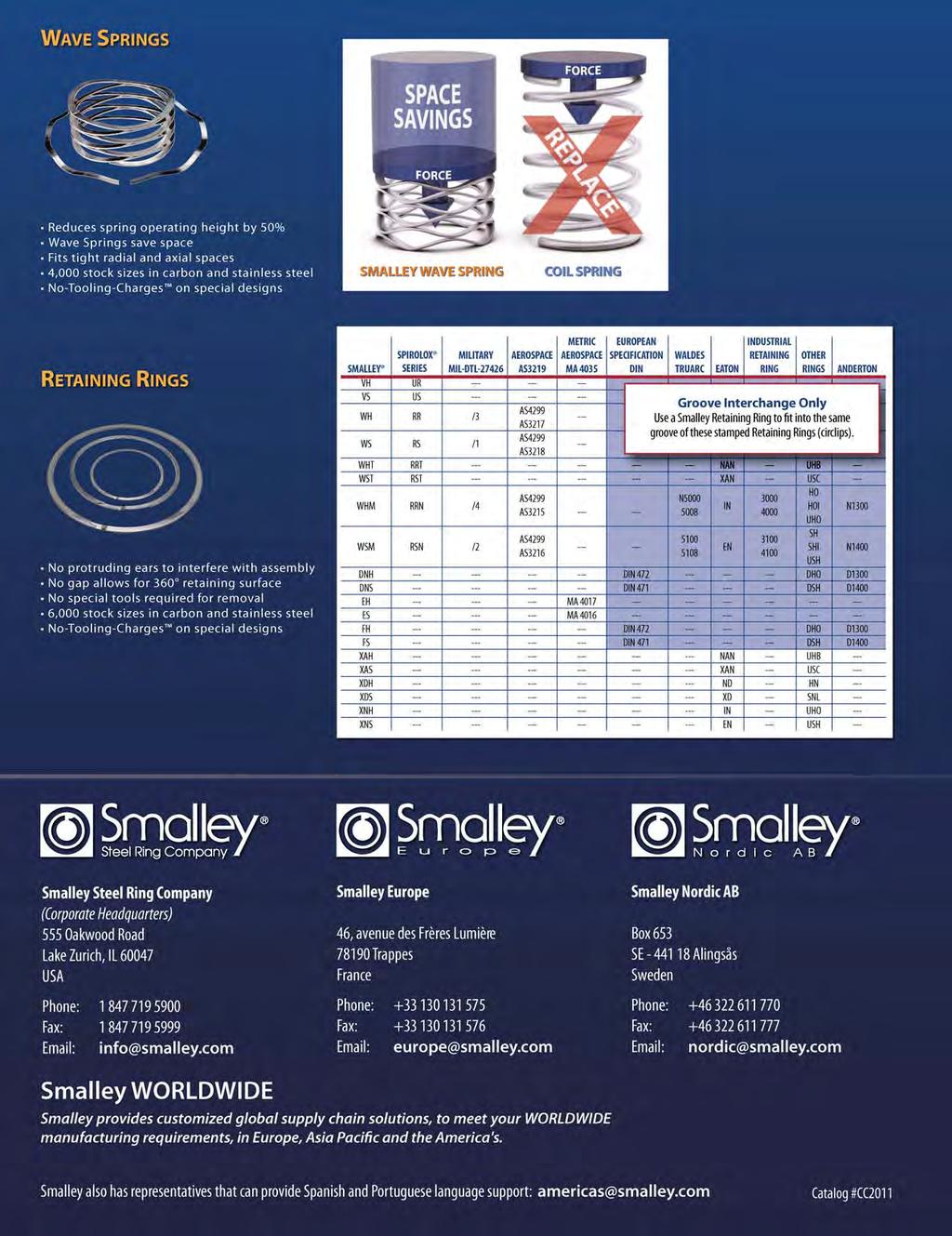
132
Wave Spring Introduction
 Wave Spring Introduction All Springs Are Not Equal Smalley Wave Springs offer the unique advantage of space savings when used to replace coil springs. By reducing spring operating height, wave springs
Spiral Retaining Rings & Wave Springs
 Engineering and Parts Catalog Stock Sizes Over 7 000 items Carbon & Stainless Steel Special Designs No-Tooling-Charges 5 mm - 2 300 mm / 0,200 in - 90 in Spiral Retaining Rings & Wave Springs www.smalley.com
THE ENGINEER S CHOICE
 THE ENGINEER S CHOICE When engineers seek a higher level of precision and performance in retaining rings, wave springs or constant section rings, there s only one choice: Smalley. From aerospace to automotive,
ENGINEERING AND PARTS CATALOG
 THE ENGINEER S CHOICE ENGINEERING AND PARTS CATALOG READY TO SHIP OVER 0,000 STANDARDS CARBON AND STAINLESS STEEL CUSTOM ENGINEERED PRODUCTS.00" TO 0" 5 MM TO,000 MM NO-TOOLING CHARGES smalley.com READY
Ring Introduction. Advantages of Spirolox Retaining Rings. Spirolox Retaining Rings offer many advantages over stamped retaining rings
 Ring Introduction Advantages of Spirolox Retaining Rings Spirolox Retaining Rings have No Ears to Interfere in your assembly! Spirolox Rings are manufactured by coiling the ring from flat wire. This unique
PARTNERS IN EXCELLENCE
 PARTNERS IN EXCELLENCE 40 Year Partnership With decades of experience, TFC is the leading European supplier of Smalley Spirolox Retaining Rings, Snap Rings and Wave Springs. Extensive Stockholding Smalley
SCHNORR Product range
 SCHNORR Product range Disc springs Bolt locking systems DISC SPRING ENGINEERING DISC SPRING ENGINEERING Grown competence for highest precision. Adolf Schnorr, who founded our business in 1908, showed true
Total Quality Management. Quick and Accurate Response to Inquiries. As-Promised Deliveries. Fair and Competitive Prices
 FORGED SHAPES 1 2 MISSION STATEMENT The Anderson Shumaker team is dedicated to earning your loyalty and gaining your trust through: Total Quality Management Quick and Accurate Response to Inquiries As-Promised
BAUMANN SPRINGS Springs and Stampings for the World.
 Welcome BAUMANN SPRINGS Springs and Stampings for the World. SPIRAL SPRINGS COMPRESSION SPRINGS WAVE SPRINGS ASSEMBLIES HUBCAP & RETAINING TENSION AND TORSION SPRINGS MICRO SPRINGS PRESSINGS AND STAMPINGS
TYPE 37FS Fully Split Seal
 A Primary Ring B Mating Ring C Compression Ring D Sealing Ring E Gland Plate F Clamp Ring G Drive Ring H Fasteners I Retaining Ring J Cord Segment I E C F B A D 37FS H J G Product Description The Type
l Cylindrical Bearings. Keeping the world in motion >>
 1-800-708-2128 l www.rbibearing.com Cylindrical Roller Bearings Keeping the world in motion >> High Quality. Peak Performance. Cost Efficient. AXPB and RBtech recently developed a joint venture/partnership
Choosing the Correct Roller Housed Unit Step by Step
 Technical Article Choosing the Correct Roller Housed Unit Step by Step by Brian Berg, Karen Cunningham and Mark Flaherty, The Timken Company Table of Contents: Start With The Basics 2 Housing Type and
Mubea Disc Springs. engineering for mobility
 As a global partner of the automobile industry, Mubea has divisions worldwide. We develop, manufacture, and sell highquality suspension springs and stabilizer bars, valve springs, disc springs, hose clamps,
CONTRACT MANUFACTURER OF PRECISION POWDERED METAL PARTS
 ASCO Sintering Co. CONTRACT MANUFACTURER OF PRECISION POWDERED METAL PARTS Precision Powdered Metal Gears Net Shape to AGMA 8 Certification at reduced cost Executive Summary Asco produces over 16,000,000
Precision Close Tolerance Wear Guides
 MACROTECH POLYSEAL, INC. Service, Solutions, Performance Precision Close Tolerance Wear Guides WGT-1000 REV #10003 Manufacturing Capacity Macrotech Polyseal produces high precision Wear Guides in high
~ CLAUSING. lteavy dafy DRILL PRESSES SEE YOUR DEALER
 ~ CLAUSING 20 lteavy dafy DRILL PRESSES SEE YOUR DEALER CATALOG 2220 CLAU - lng 20" drill presses PRODUCTION rated 7/8" in steel - -/8" in cast iron HEAVY-DUTY COUNTERSHAFT DRIVES: positive-power variable
Belt Systems & Belt Products
 Belt Systems & Belt Products Advanced Technology Solutions Caterpillar offers a full range of rugged belt conveyor systems and products unsurpassed in performance and service life custom-designed solutions
LOAD BEARING ROLLER ASSEMBLIES Engineering Data Installation Notes
 Installation Notes INSTALLING STUD TYPE LOAD BEARING ROLLER ASSEMBLIES Mounting holes should be machined to the nominal stud size within +.001/-.000 (+.025mm / -.000mm) tolerance. When properly aligned,
OETIKER. Technical Data Sheet. 1-Ear Clamps. 1-Ear Clamps with Insert. 2-Ear Clamps. Connecting Technology. Dimple. Ear. Ear width.
 OETIKER width Technical Data Sheet 1- Clamps Product Group 153 Insert width 1- Clamps with Insert Product Group 154 width (Double clamping range) 2- Clamps Product Group 101 & 151 Connecting Technology
Stainless Steel Aeration Equipment Specification
 Section 15 Stainless Steel Aeration Equipment Specification Part 1 - General 1.01 Description A. Scope of Work 1. Furnish, install and test aeration system including air mains, drop pipes, valves, expansion
Xinxiang Degong Machinery Co.,Ltd. CRANE WHEELS catalog
 CRANE WHEELS catalog crane wheels introduction Crane wheels are replaced because of flange wear, flange breakage, and mechanical overloads characterized by pitting and spalling. Each of these inservice
VIKING. Heavy-Duty, Foot-Mounted Sealless Internal Gear Pumps. Operating Range1: Nominal Flow Rates: Section 635 Page 635.
 Page 635.1 Heavy-Duty, Foot-Mounted Sealless Internal Gear Pumps Operating 1: Series 8124A Model H8124A Nominal Flow Temp. 2 Viscosity (GPM) 15-200 (M 3 /hr.) 3.4-45 (PSI) To 200 PSI (Bar) To 14 Bar (
By Gorbel Inc. The Best in the Business is Better Than Ever!
 By Gorbel Inc. The Best in the Business is Better Than Ever! Cleveland Tramrail by Gorbel: A Name Built on Quality Since 1977, Gorbel Inc. has specialized in overhead material handling solutions, providing
HINDON FORGE PVT. LTD.
 www.hindonforge.net Hammering Quality into Forgings An ISO 9001:2000 Certified Co. HINDON FORGE PVT. LTD. Manufacturers of Critical Steel Forgings and Flanges MANUFACTURERS & EXPORTERS OF ALL KINDS OF
RKB spherical roller bearings: executions and applications
 RKB spherical roller bearings: executions and applications RKB spherical roller bearings: endowed with the latest technology RKB spherical roller bearings are produced with the latest technology available:
METRIC DRIVELINES & COMPONENTS AFTERMARKET PRODUCT GUIDE METRIC DRIVELINES & COMPONENTS
 AFTERMARKET PRODUCT GUIDE METRIC DRIVELINES METRIC DRIVELINES 85 SAFETY SECTION SAFETY 2SECTION WARNING! Be certain to disengage PTO shaft and to turn off the tractor before making any operational maintenance
Your Key To Quality & Savings. Your One-Stop Solution For High Performance Powder Metal Parts ISO 9001:2008 CERTIFIED
 Your Key To Quality & Savings Your One-Stop Solution For High Performance Powder Metal Parts ISO 9001:2008 CERTIFIED 2 Discover The Symmco Advantage From its humble beginnings, Symmco has evolved into
Technical Guide for Glass Cutting Section 2 - Three Basic Categories of Cutting
 Section 2 - Three Basic Categories of Cutting Three basic categories of glass cutting represent the majority of cutting applications straight-line machine cutting, machine pattern cutting and hand cutting.
SPECIFICATIONS - DETAILED PROVISIONS Section Progressing Cavity Pump C O N T E N T S
 SPECIFICATIONS - DETAILED PROVISIONS Section 11938 - Progressing Cavity Pump C O N T E N T S PART 1 - GENERAL... 1 1.01 GENERAL... 1 1.02 RELATED SPECIFICATION SECTIONS... 1 1.03 MANUFACTURERS... 1 PART
Double Containment DESIGN & INSTALLATION GUIDE TECHNICAL INFORMATION. Visit our web site
 Double DESIGN & INSTALLATION GUIDE TECHNICAL INFORMATION Visit our web site www.spearsmfg.com 1326 The information contained in this publication is based on current information and Product design at the
Electronic Equipment in Motion: Slide into smoother performance for your products and your processes
 Electronic Equipment in Motion: Slide into smoother performance for your products and your processes More than a century of supporting the world s premiere OEMs has given us a proven track record for developing
terminal blocks
 E B Y E L E C T R O terminal blocks S I N C E 1 9 4 5 The EBY Connection Over 60 Years EBY Electro, Inc. has answered OEM production and service requirements since 1945 by supplying specialized components
Offshore/Marine. Lubron. Self-Lubricating PTFE Composite Bearings. Lubron Bearing Systems. Bearings to move the world.
 Offshore/Marine Lubron TX Lubron Bearing Systems Bearings to move the world. LUBRON TX self-lubricating bearings combine high performance reinforcing polyester fibers with thermosetting resins and PTFE
DOUBLE CONTAINMENT DESIGN & INSTALLATION GUIDE
 DC-3-0604 Spears Double Containment Systems are engineered for ease of installation and lower associated installation costs. Complete systems include all necessary components - carrier pipe, containment
Rod End. General Catalog A-941
 Rod End General Catalog A Technical Descriptions of the Products B Product Specifications (Separate) Features and Types... Features of the Rod End... Features... Special Bearing Alloy... Performance Test
DISTITEC Srl. Bearings for. rolling mills. Special bearings for steel industry DS 0001 MILL 2014
 DS 0001 MILL 2014 Srl Bearings for Special bearings for steel industry rolling mills The realization of this catalog occurred in tighter of data contained therein. Due to the ongoing technical evolution
Table of Contents. Journal Bearings 1. Journal Bearing Overview...Page Product Data...Pages 58-59
 Table of Contents Radial Roller earings 1. Radial Roller earing Overview...Pages 4 - Configurations and Numbering System...Pages 6-9 3. Retainer Selection...Page 1 Series Code and Race and Roller Material...Page
BLOCKS- MILLER HI-LIFT BLOCKS
 Wide capacity range available Standard capacities to 300T Design factor 4:1 Larger capacities available Sheaves from 8 to 36 Wire rope sizes to 1 ¾ Hooks- high quality forged alloy steel Per DIN 15401
Precision feeler gage, calibrated shim steel and Specialty Spring Steels
 Precision feeler gage, calibrated shim steel and Specialty Spring Steels 2011 Your partner for precision steels We offer an extensive range of precision feeler gages and shim steel which covers most product
Worldwide Leadership in Wire and PCB Manufacturing Products
 Worldwide Leadership in Wire and PCB Manufacturing Products Leadership demands commitment and TE is committed to meeting manufacturing needs worldwide with technology, products and systems, and service.
Duraflex and Megaflex can be tested under simulated operating conditions prior to shipment. Environmental Test Chamber. In-house X-Ray Capabilities
 t Co-Operative Industries, we view technology as a blending of art and science in the use of new materials and production methods to further improve our products. Duraflex and Megaflex can be tested under
SECTION CRL50 AND CRL51 HEAVY GLASS TOP HUNG SLIDING DOOR SYSTEMS
 SECTION 08 32 20 CRL50 AND CRL51 HEAVY GLASS TOP HUNG SLIDING DOOR SYSTEMS Page 1 of 6 USE THIS SECTION WHEN SPECIFYING OVERHEAD SUPPORTED GLASS PANEL PARTITIONS. SECTION INCLUDES OVERHEAD TRACK ASSEMBLY,
A CHECKLIST FOR QUALITY. Seven Questions to Gauge Quality in Metal Stamping Suppliers
 A CHECKLIST FOR QUALITY Seven Questions to Gauge Quality in Metal Stamping Suppliers The Value of Quality Quality. It s the #1 concern for OEM engineering and purchasing managers when evaluating and measuring
AUTOMATIC CUT-OFF LA THES for Bar and Tubular Stock
 AUTOMATIC CUT-OFF LA THES for Bar and Tubular Stock Chamfer, Form, Groove, Cut Off Up to 8" Tubing; Up to 3" Bar Stock Rugged Construction Application Engineering Automatic Load/Unload Maximum Productivity
Khodiyar Industrial Corporation
 RAJKOT - GUJARAT 9-Navarangpara, Opp-Poonam Foundry, Rajkot-360004, Gujarat (INDIA) Phone: +91-281-2388697, Fax: +91-281-2388697 Email: info@kic.co.in, sales@kic.co.in www.kicdieselengineparts.com 1 Introduction
Air Compressor Series.
 Air Compressor Series Leading the Industry FS-Elliott is best positioned to provide you with the highest quality air compressors, parts, and services to ensure optimal performance and reliability of your
SUGGESTED SPECIFICATIONS Pump Frames through 64132
 TYPE HBB - HORIZONTAL SOLIDS-HANDLING WASTEWATER PUMPS Pump Frames 44081 through 64132 GENERAL Furnish and install Horizontal Flexible Coupled Dry Pit Pumping Units complete with all accessories and appurtenances
Model TS-100 Tubing Spider Installation, Operation, Service and Parts Book Manual
 Model TS-100 Tubing Spider Installation, Operation, Service and Parts Book Manual WPI WELLKIN Inc. 8401 Industrial Dr. Pearland, TX 77584 PH: (281) 992-2064 FX: (281) 992-2076 E-mail: sales@wpiwellkin.com
Roll Marking Machines
 Roll Marking Machines Serving your marking needs since 1895 (800) 323-1332 (847) 647-7117 www.gtschmidt.com Introduction to roll marking The Basics Of Roll Marking Schmidt pioneered roll marking over 65
PRECISION MEASURING UNIT FOR THE SHOP FLOOR
 PRECISION MEASURING UNIT FOR THE SHOP FLOOR APPLICATIONS HIGH PRECISION GAUGING IN THE PRODUCTION PROCESS 3 CAM SHAFTS 3 CRANK SHAFTS 3 GEAR SHAFTS 3 DRIVE SHAFTS TYPICAL MEASURING TASKS Dimensional, position,
Cement Industry CHAINS and SPROCKETS
 Cement Industry CHAINS and SPROCKETS HEAVY DUTY CEMENT ELEVATOR CHAIN ALLIED-LOCKE Heavy Duty SS Class Steel Bushed Chains are designed and constructed to withstand the rigorous conditions encountered
Precision Roller Pinion System Models RPS16, RPS20, RPS25, RPS32, RPS40 LINEAR MOTION CONTROL PRODUCTS FORM NO. L A-1204.
 LINEAR MOTION CONTROL PRODUCTS User Manual Precision Roller Pinion System Models RPS16, RPS20, RPS25, RPS32, RPS40 1 DANGER Read this manual carefully before installation and operation. Follow Nexen's
Unique SKF taper roller bearings: Solutions for demanding operating conditions and long service life.
 Unique SKF taper roller bearings: Solutions for demanding operating conditions and long service life. SKF TQ-Line SKF CL7C SKF Explorer SKF taper roller bearings Performance classes The design and production
BALL BEARING DIE SETS
 www.danly.com TRUSTED SOLUTIONS AND INNOVATION BALL BEARING DIE SETS Wide selection of components Effective in high speed applications Complex machining to your print www.danly.com BALL BEARING DIE SETS
RYSON SPIRAL CONVEYORS
 RYSON SPIRAL CONVEYORS VERTICAL CONVEYING SOLUTIONS About Ryson International Ryson International, Inc. was founded in 1995 and specializes in Vertical Conveying Solutions. We manufacture a full line of
NUCLEAR. Nuclear Reactor Pressure Vessel Seals
 NUCLEAR Nuclear Reactor Pressure Vessel Seals SEALING CONCEPT Technetics Group is the world s leading manufacturer of Nuclear Reactor Pressure Vessel (RPV) Closure Head Seals. In addition, Technetics Group
Stock and Custom Springs
 Stock and Custom ISO 9001 Registered Call: 888-777-4647 (888-SPRINGS) Visit: leespring.com Email: sales@leespring.com Fax: 888-426-6655 Why Choose Lee Spring? Selection Lee Spring offers 25,000+ products
MANUFACTURING TECHNOLOGY
 MANUFACTURING TECHNOLOGY UNIT II Hot & Cold Working Forging & Rolling Mechanical Working of Metals In this method no machining process is carried out, but it is used to achieve optimum mechanical properties
The specialist of tailor made tubes and components
 The specialist of tailor made tubes and components The core business of AMT is the supply of "custom made" carbon and alloy precision steel tubing to manufacture mechanical parts and elements Precision
DESIGN GUIDE. Precision ground Ball Screws ENGINEERED BALL SCREW ASSEMBLIES FULL SERVICE REPAIR CONTACT US
 DESIGN GUIDE Precision ground Ball Screws ENGINEERED BALL SCREW ASSEMBLIES FULL SERVICE REPAIR service & replacement CONTACT US 3 EASY WAYS: 1. Go to our website at dynatect.com 2. Call us at 800-298-2066
Coastal Bearing Repair Services
 Coastal Bearing Repair Services Breathe new life into worn or damaged bearings The Coastal reconditioned bearings program provides an economical means to extend the life of heavy duty bearings that have
Ceramic Linear Bearings
 Ceramic Linear Bearings ov-ceramic-bearings-divider - Updated - 18-09-2017 163 Ceramic Linear Bearings Technical Information Ceramic linear bearings Self-lubricating These ceramic coated linear bearings
Rolling processes. Fig. (5-1)
") Page1 Rolling processes 5-1 introduction: Rolling is the process of reducing the thickness or changing the cross section of a long workpiece by compressive forces applied through a set of rolls, as shown
Page1 Rolling processes 5-1 introduction: Rolling is the process of reducing the thickness or changing the cross section of a long workpiece by compressive forces applied through a set of rolls, as shown
Technology that works for you.
 Technology that works for you. WATER WELL & MINERAL EXPLORATION Drilling accessories designed for use in Water Well and Mineral Exploration are illustrated in this brochure and are manufactured to the
SECTION CRL70 HEAVY GLASS TOP HUNG SLIDING DOOR SYSTEMS
 Page 1 of 6 SECTION 08 32 20 CRL70 HEAVY GLASS TOP HUNG SLIDING DOOR SYSTEMS USE THIS SECTION WHEN SPECIFYING OVERHEAD SUPPORTED GLASS [OR WOOD] PANEL PARTITIONS. SECTION INCLUDES OVERHEAD TRACK ASSEMBLY,
QForm. Form3D. Advanced software for forging simulation
 QForm Form3D Advanced software for forging simulation The goals of forging technology : Make the parts of the required shape Provide required properties Do it in time and at the lowest cost Forging process
DETAIL SPECIFICATION RINGS, RETAINING, SPIRAL (UNIFORM CROSS SECTION)
") INCH-POUND 25 September 1997 SUPERSEDING MIL-R-27426A 27 August 1996 1. SCOPE DETAIL SPECIFICATION RINGS, RETAINING, SPIRAL (UNIFORM CROSS SECTION) This specification is approved for use by all Departments
INCH-POUND 25 September 1997 SUPERSEDING MIL-R-27426A 27 August 1996 1. SCOPE DETAIL SPECIFICATION RINGS, RETAINING, SPIRAL (UNIFORM CROSS SECTION) This specification is approved for use by all Departments
Conventional Paper-II-2012
 Conventional Paper-II-2012 1.a. Determine the maximum and minimum transmission angle of the mechanism shown which is driven by member O. 1 B 3cm s 4cm p l 8cm b. For a cam whose acceleration is constant
Micro-Precision Coil and Formed Wire Products for the Medical Device Industry
 Micro-Precision Coil and Formed Wire Products for the Medical Device Industry Precision Metal Components For Medical Devices Specialized, complex parts and sub-assemblies Extreme diameter and length capabilities
D-M-E Edge Mold Bases
 D-M-E THE LOWEST-PRICED MOLD BASE ON THE MARKET IS IN STOCK IN 70 DIFFERENT SIZES D-M-E 16 Providing a Competitive Advantage THE NEW EDGE MOLD BASE GIVES YOUR CUSTOMERS A COMPETITIVE ADVANTAGE What is
VIKING. Heavy-Duty, Foot-Mounted Sealless Internal Gear Pumps. Operating Range1: Nominal Flow Rates: Section 635 Page 635.
 VIKING Section 635 Page 635.1 Heavy-Duty, Foot-Mounted Sealless Internal Gear Pumps Model H8124A Operating Range1: Series 8124A Nominal (GPM) 15-500 Flow (M 3 /hr.) 3.4-114 Pressure (PSI) To 200 PSI Range
DIAGRAM FOR CALCULATING PIPE SIZES, DISCHARGE VELOCITIES AND LOSS OF HEAD IN STANDARD STEEL PIPE PIPE FRICTION LOSS CHART
 DIAGRAM FOR CALCULATING PIPE SIZES, DISCHARGE VELOCITIES AND LOSS OF HEAD IN STANDARD STEEL PIPE PIPE FRICTION LOSS CHART (For Cast Iron and Concrete Pipes See Note at Right) Lay a straightedge on scales
SECTION EZ-SLIDE 80 AND 180 HEAVY GLASS TOP HUNG SLIDING DOOR SYSTEMS
 Page 1 of 6 SECTION 08 32 20 EZ-SLIDE 80 AND 180 HEAVY GLASS TOP HUNG SLIDING DOOR SYSTEMS USE THIS SECTION WHEN SPECIFYING OVERHEAD SUPPORTED GLASS PANEL PARTITIONS. SECTION INCLUDES OVERHEAD TRACK ASSEMBLY,
SUGGESTED SPECIFICATIONS
 SUGGESTED SPECIFICATIONS SERIES 3000 SUSPENDED, SCREENED WET-PIT PUMPS PART 1 GENERAL 1.1 DESCRIPTION Work Included: Under this section, the contractor shall provide all labor, equipment and material necessary
Bulk Deformation Processes
 Bulk Deformation Processes Bachelor of Industrial Technology Management with Honours Semester I Session 2013/2014 TOPIC OUTLINE What is Bulk Deformation? Classification of Bulk Deformation Processes Types
Offshore Drilling Ltd. Primary Cementing Products
 Primary Cementing Products ENEROIL BEYOND ENGINEERING EXCELLENCE Eneroil welcomes you to its world of precision, quality and service. A world which has existed for the last two decades providing excellence
Rollers The Widest Choice
 Rollers The Widest Choice A Company of ThyssenKrupp BERCO S.p.A. Berco Moving Your Business Ahead Leadership in Undercarriage For about 90 years Berco s leadership and research has resulted in the greatest
Slide Retainers. Tapped Dowel. Maximum. Catalog Number. Shoulder Pin. Screw Weight
 Slide Retainers A compact method of slide retention that eliminates the use of springs or costly hydraulic systems. Interference with machine tie bars or safety gates is eliminated because the slide retainer
SCHNORR Product range. Disc springs Bolt locking systems
 SCHNORR Product range US Disc springs Bolt locking systems Disc Spring Engineering DISC SPRING ENGINEERING As a pioneer of the disc spring application Adolf Schnorr founded the family-owned company in
Appliance Storage in Motion:
 Appliance Storage in Motion: Slide performance opens the door to a superior customer experience When it comes to the daily experience of using major appliances, the quality, performance, and feel of the
Thank You for 100 Years of Support
 Thank You for 100 Years of Support Lee Spring proudly reaches a milestone year in 2018 as we celebrate our centennial anniversary. Founded in 1918 in Brooklyn New York; Lee Spring s longevity and strength
Thermocouples W A T L O W
 W A T L O W General Applications Over 90 years of manufacturing, research and design makes Watlow a world class supplier of temperature measurement products. We have designed and manufactured millions
CHAPTER 1 INTRODUCTION
 CHAPTER 1 INTRODUCTION 1.1. GENERAL INTRODUCTION Shell and tubes heat exchangers are used in a wide variety of applications in many industries for heat transfer purposes. The integrity of tube-tubesheet
Pallet-Handling Systems for Flexible Manufacturing
 Pallet-Handling Systems for Flexible Manufacturing Modular. Flexible. Versatile. Introduction to mk mk North America is a member of the mk Technology Group and a leading worldwide manufacturer of pallet-handling
DIVISION 15- MECHANICAL Section Fire Pumps
 DIVISION 15- MECHANICAL Section 15320 Fire Pumps 1.00 PART 1 -GENERAL 1.01 DESCRIPTION OF WORK: A. Provide pumps for fire suppression. 1.02 SECTION INCLUDES: A. Vertical Turbine Fire Pump RELATED DOCUMENTS:
Products and Services
 Products and Services Experts in special steel long products DEUTSCHE EDELSTAHLWERKE is a leading manufacturer of special steel long products. Our broad product range has acquired us a virtually unique
Fluid Automation Solutions for. Beverage Bottling & Packaging
 Fluid Automation Solutions for Beverage Bottling & Packaging Select from the industry s widest array of fluid control and fluid power solutions for beverage bottling and packaging. No other supplier matches
TEXAS DEPARTMENT OF TRANSPORTATION PROCUREMENT DIVISION PRESS, GYRATORY, ASPHALT, PORTABLE PUBLICATION
 TEXAS DEPARTMENT OF TRANSPORTATION PROCUREMENT DIVISION PRESS, GYRATORY, ASPHALT, PORTABLE PUBLICATION SPECIFICATION NO. TxDOT 845-63-58 * REVISED: AUGUST 2014 This specification is a product of the Texas
Hydraulic Sealing Products
 Hydraulic Sealing Products Complete family of proven products, backed with full technical support, for General duties Arduous conditions Critical applications Standard & non-standard sizes High Performance
DETAIL SPECIFICATION RINGS, RETAINING, SPIRAL (UNIFORM CROSS SECTION)
") INCH-POUND MIL-DTL-27426B 25 September 1997 SUPERSEDING MIL-R-27426A 27 August 1996 1. SCOPE DETAIL SPECIFICATION RINGS, RETAINING, SPIRAL (UNIFORM CROSS SECTION) This specification is approved for use
INCH-POUND MIL-DTL-27426B 25 September 1997 SUPERSEDING MIL-R-27426A 27 August 1996 1. SCOPE DETAIL SPECIFICATION RINGS, RETAINING, SPIRAL (UNIFORM CROSS SECTION) This specification is approved for use
Fittings, Materials and Tubing Guide. Instrumentation Products
 Fittings, s and Tubing Guide Fittings, s and Tubing Guide Instrumentation Products Single/Double Ferrule Instrument CPI / A-LOK Tube Fittings Introduction Parker CPI / A-LOK Instrumentation Tube Fittings
Optima Dipper Systems Product Overview
 Dipper Systems Product Overview Service Leader Zero Harm A breakthrough approach to superior dipper performance Mine-matched dippers P&H dippers, with nominal while at the same time working Highest Production
The Global Leader in Precision Parts
 The Global Leader in Precision Parts Welcome to Century Specialties Company Overview Headquartered in Traverse City, MI, Century, Inc. is a privately held precision manufacturing company. Comprised of
PTFE BELLOWS POLY FLUORO LTD. POLY FLUORO LTD.260A. Bommasandra Industrial Area, Hosur Road, Bangalore TECHNICAL SPECIFICATION
 PTFE BELLOWS TECHNICAL SPECIFICATION 1. MATERIALS 1.1 PTFE Only virgin (not reprocessed) PTFE conforming to ASTM D 1457, type III, IV or V shall be used for the production of bellows; the PTFE raw material
SECTION 552 HELICAL ANCHORS AND HELICAL PILES
 SECTION 552 HELICAL ANCHORS AND HELICAL PILES DESCRIPTION 552.01 This work pertains to furnishing and installing helical anchors and helical piles shown in the Contract in accordance with the Drawings
Optional Drill Pipe Products
 Drill Pipe At RDT we understand our customer s need for durability and performance when choosing the drill pipe that they will use. Each joint of pipe we produce goes through our intense quality assurance
HIGH SEAL ULF Live Loaded Packing System
 Instruction Manual HIGH-SEAL Live-Loaded Packing HIGH SEAL ULF Live Loaded Packing System Contents Introduction... 1 Scope of Manual... 1 Description... 2 Spring Selection... 3 Installation... 3 Parts
Contents. dimensions and weights external loads deflection and testing installation...17
 GRAVITY SEWER Contents 01 02 03 04 05 06 07 08 09 product description...2 short form specification...5 dimensions and weights....................... 6 flow/discharge charts....................... 8 external
Precision Turned Parts since 1846
 Precision Turned Parts since 1846 Tradition & Innovation Founded in 1846 by Samuel Laubscher our company has remained family owned through the present day. We have been constantly growing and evolving
YOUR ONE STOP FABRICATION SOURCE
 YOUR ONE STOP FABRICATION SOURCE YOUR RELIABLE ONE STOP FABRICATION SOURCE! Our main fabrications facility is a modern full service metal fabrication shop committed to quality and customer service. We