Table of Contents. Journal Bearings 1. Journal Bearing Overview...Page Product Data...Pages 58-59
|
|
|
- Flora Patrick
- 5 years ago
- Views:
Transcription
1
2
3 Table of Contents Radial Roller earings 1. Radial Roller earing Overview...Pages 4 - Configurations and Numbering System...Pages Retainer Selection...Page 1 Series Code and Race and Roller Material...Page 11. Technical A. Class of Precision...Page 12. asics of Load Ratings and earing Selection Criteria...Page 12 C. Limiting Speed...Page 12 D. Limiting Speed Graph...Page Product Data...Pages Applications...Pages Thrust earings 1. Thrust earing Overview...Pages 3-31 Cylindrical Thrust A. Types...Pages Numbering System...Page 3 C. Product Data...Pages Tapered Thrust A. Types...Pages Numbering System...Page 43 C. Product Data...Pages 44-4 Tandem Thrust A. Designs...Pages Product Data...Pages Special Designs...Page 1 6. Applications...Pages 2 - Journal earings 1. Journal earing Overview...Page 7 Product Data...Pages 8-9 Engineering 1. Table of Contents...Page 6 Gaging Practices...Pages Tolerances A. Radial earings, REC 1, 3 and...pages Journal earings...page 64 C. Thrust earings...pages 6-67 Life - Load - Speed...Pages Fitting Practice A. Radial earing Unmounted Internal Clearance...Pages Radial earing Mounting Practice - Shaft and Housing Fits...Pages C. Thrust earing Mounting Practice - Shaft and Housing Fits...Pages D. Journal earing - Shaft and Housing Fits...Page Lubrication...Pages

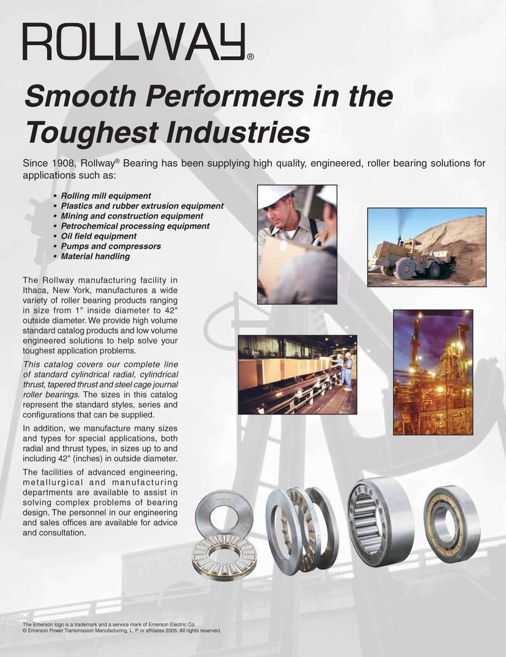
4 earings for Demanding Applications Rollway Cylindrical Radial Roller earings Catalog sizes and engineered-to-order bearing designs readily available. REC precision class capability Extra capacity designs Multiple retainer designs available High temperature designs available Special features... Notches Slots Aligning features Carburizing grade materials Rollway Roller Thrust earings Catalog sizes and engineered-to-order bearing designs readily available. Cylindrical roller designs catalog and engineered Aligning, banded and double acting designs available Tapered roller designs TTHD and TTVF Cantilever designs for minimal shoulder support Tandem thrust 2-8 stage designs High temperature designs available High speed designs available Engineered earings for Your Applications 2
5 Radial Roller earings Radial Roller earings... Pages 4 thru 29 Index - earing Types E-####- E-####-U -#### -### L-####-U L-#### NJ-### LP-####-U -#### P-### U-####-E -#### N-### U-####-L -#### U-####-LP MN-#### U-####- UM-####- M-#### MS-#### Cylindrical Thrust earings...pages 3 thru 4 T-### AT-### CT-## WCT-## DT-### DAT-### SDT-### Tapered Thrust earings...pages 41 thru 4 T-### T-######-F Tandem Thrust earings...pages 46 thru 1 TA-###### TM-###### TAC-###### TMC-###### TAD-###### TMD-###### TAF-###### TMF-###### TAH-###### TMH-###### Journal Roller earings...pages 7 thru 9 D-### -### -###-7 WS-### E-###-6 3

6 Radial Roller earings... Since 198 Rollway earing produced high quality, engineered cylindrical radial roller bearings. There are hundreds of standard designs available as well as the capability to engineer bearings to help satisfy your demanding applications. 4

7 In the past we have solved some of the most demanding bearing challenges: High speed bearings for aerospace transmissions High temperature bearing designs for poly-reactor and corrugating equipment Designs for applications using low viscosity lubricants Designs for vibratory and orbiting applications Designs requiring anti-rotation features on the races earings with outside diameters of 42" In addition to providing solutions to industry s toughest bearing applications, Rollway bearings are manufactured in many standard catalog sizes and styles: Multiple configurations per basic size Many different series available Steel and brass retainer options Extra capacity designs Rollway Standard Designs Unmounted internal clearances - Rollway s standard is C3, though other unmounted internal clearances are readily available. Races - manufactured from vacuum degassed through hardened bearing grade steel. Surfaces are precision ground to REC 1 and stabilized to 33 F. Standard retainer options include segmented steel or machined brass. All radial rollers are crowned. Extra capacity bearing designs have larger rollers, maximizing the load carrying potential of the bearing s cross sectional area.
8 Radial Roller earings Configuration and Numbering System Rollway cylindrical radial roller bearings are available in a vast variety of sizes and configurations ranging from standard cataloged, 4mm ID bearings to 1,16mm outside diameter, special engineered bearings. This section of the catalog covers Rollway cylindrical radial roller bearing configurations, part numbering, material, retainer design and limiting speeds. Inner Race Separable, oth Directions Number Systems E-####-U E-####- -#### -### Two-flange (or retaining rings) outer race, straight inner race, separable bearing. For applications where axial float in both directions is desired. Roller assembly remains with the outer race. Inner Race Separable, One Direction Two Piece Inner Race, Four-Flange Design Number Systems L-####-U L-#### NJ-### Number Systems LP-####-U -#### P-### Two-flange outer race, one-flange inner race, separable bearing. For applications where axial float in one direction and axial retention in the other direction is desired. Roller assembly remains with the outer race. Will carry light thrust loads in one axial direction. Outer Race Separable oth Direction Two-flange outer race, two-flange inner race with one flange plate, separable bearing. For applications where axial retention in both directions is desired. Roller assembly remains with the outer race. Will carry light thrust loads in both axial directions. Outer Race Separable One Direction Number Systems U-####-E -#### N-### Number Systems U-####-L -#### Straight outer race, two-flange inner race, separable bearing. For applications where axial float is desired. Roller assembly remains with the inner race. Two-Piece Outer Race Four-Flange Design One-flange outer race, two-flange inner race, separable bearing. For applications where axial float in one direction and axial retention in the other directions is desired. Roller assembly remains with the inner race. Will carry light thrust loads in one direction. Non-Separable Number Systems U-####-LP MN-#### Number Systems U-####- MS-#### Or when supplied with a full complement of rollers. Number Systems UM-####- M-#### Two-flange outer race with one flange plate, two-flange inner race, separable bearing. For applications where axial retention in both directions is desired. Roller assembly remains with the inner race. Will carry light thrust loads in both axial directions. Two snap-ring flange outer race, two-flange inner race, non-separable bearing. No axial retainer of outer race is required when inner race is properly mounted on shaft. See application drawings. Will not carry thrust loads. 6
9 Radial Roller earings Configuration and Numbering System Rollway Numbering Systems... Over the years the Rollway product offering has increased. Each new product line has its own numbering system, resulting in the current offering of multiple nomenclatures. The three basic systems are Tru-Rol, MAX and ISO, described below and on the following two pages. TRU-ROL Numbering This system for radial bearings is broken into 4 parts; prefix, size designator, suffix and variation code. Example: E-1212-U-199 Variation code Suffix Size designator Prefix Prefix - Inner race description E... Inner race separable both directions. L... Inner race separable one direction. LP... Two-piece inner race, one part is separable one direction, the other is a thrust plate to form a channeled race assembly. U... Inner race with two flanges, non-separable. UM... Inner race with two flanges, non-separable, full complement of rollers. NONE... No inner race supplied. Size Designator Available series; 1, 12, 13, 2, 3 and 6 Suffix - Outer race description E (EMR)... Outer race separable both directions. L (LMR)... Outer race separable one direction. LP (LPMR)... Two-piece outer race, one part is separable one direction, the other a thrust plate to form a channeled race assembly. U (UMR)... Outer race with two flanges, non-separable.... Outer race with two snap rings to retain the roller set, non-separable. J... Outer race with one snap ring and one flange to retain the roller set, non-separable. Variation Codes - Variation codes are divided into two categories; special and standard. Special variation codes to 129 are numerically assigned codes that designate the variation from standard (example 11 = 1st variation, 12 = 2nd variation, etc.). These bearing code numbers do not in any way reference the modification from standard. Engineering must be contacted for information concerning a particular modification. Standard variation codes... 1 to 99 and 13 to 199 are code numbers representing standard modifications. The most popular are listed below: K - Over sized OD. 3 - Rollway internal clearance Class 3. - Rollway internal clearance Class. 7 - Rollway internal clearance Class Outer race with SAE ring groove around OD Outer race with blind hole or locating slot in outer race roached retainer earing with SAE ring groove on OD and snap ring furnished. 7
10 Radial Roller earings Configuration and Numbering System MAX Numbering This system for radial bearings is broken into three parts; prefix, size designator and variation code. Example: Variation code Size designator Prefix Prefix - earing configuration description... earing assembly with roller assembly retained in inner race, outer race separable one direction.... earing assembly with roller assembly retained in inner race, outer race separable both directions. MN... earing assembly with roller assembly retained in inner race. Two-piece outer race, one part is separable one direction, the other is a thrust plate to form a channel race. MS... earing assembly with roller assembly retained in inner race. Outer race with two snap rings to retain the roller set, non-separable. M... earing assembly with roller assembly retained in inner race. Outer race with two snap rings to retain the roller set, non-separable with a full complement of rollers.... earing assembly with inner race separable both directions. Roller assembly retained in outer race. L... earing assembly with inner race separable one direction. Roller assembly retained in outer race.... earing with a two-piece inner race, one part is separable one direction, the other is a thrust plate to form a channeled race. Outer race retains the roller assembly. MR... earing with a two-piece inner race, one part is separable one direction, the other is an HJ ring to form a channel race. Outer race retains the roller assembly. Size Designator Available series; 1, 2, 3, and 1. Variation Codes - Variation codes are divided into two categories; special and standard. Special variation codes to 199 are numerically assigned codes that designate the numerical variation from standard (example 11 = 1st variation, 12 = 2nd variation, etc.). These bearing code numbers do not in any way reference the modification from standard. Engineering must be contacted for information concerning a particular modification. Standard variation codes... 1 to 99 are code numbers representing standard modifications. The most popular are listed below: 3 - Rollway internal clearance Class 3 - Rollway internal clearance Class 7 - Rollway internal clearance Class 7 8
11 Radial Roller earings ISO Numbering This system for radial bearings is broken into three parts; prefix, size designator and variation code. Example: -32-EMC3 Variation Code Size Designator Prefix Configuration and Numbering System Prefix - earing configuration description... earing assembly with inner race separable both directions. Roller assembly retained in outer race. P... earing with a two piece inner race, one part is separable one direction, the other is a thrust plate to form a channeled race. Outer race retains the roller assembly. NJ... earing assembly with inner race separable one direction. Roller assembly retained in outer race. N... earing assembly with roller assembly retained in inner race. Outer race separable both directions. Size Designator Available series; 2, 3, 22 and 23. Variation Codes - Variation codes are divided into two categories; special and standard. Special variation codes... VAA begins an alpha code assigned to designate the variation from standard (example VAA = 1st variation, VA = 2nd variation, etc.). These bearing codes do not in any way reference the modification from standard. Engineering must be contacted for information concerning a particular modification. Standard variation codes... Are code numbers representing standard modifications. The most popular are listed below: E - Extra capacity design M - Machined brass retainer C2 - AMA internal clearance symbol 2 C3 - AMA internal clearance symbol 3 C4 - AMA internal clearance symbol 4 S1 - earing is stabilized for operation at 39 F 9
 Recommended for low speed operations.")


12 Radial Roller earings Retainer Material and Construction Stamped Steel Retainer A one-piece, low carbon steel stamping. Supplied on some bearings with snap ring retention. (TRU-ROL numbering suffix of R ) Recommended for low speed operations. Segmented Steel Retainer A built-up type of retainer utilizing low carbon steel segments rigidly held between stamped, low carbon steel end plates. This is the standard retainer supplied with commercial bearings identified with the TRU-ROL numbering system. Recommended for moderate speed applications. Two-Piece Retainer This type of retainer is fabricated from brass. This is the standard retainer supplied with Rollway bearings identified with the MAX numbering system, ISO numbering system, TRU-ROL numbering system when the MR suffix is used, and any bearing with bore size over 18mm. Recommended for moderate to high speed applications. One-Piece Retainer This land piloting retainer is fabricated from brass or steel with radial retention of the rollers provided by closing the roller pocket with small projections formed by mechanically upsetting the retainer material. This retainer design is typically made to order for high speed applications, though it is applicable for other applications. 1 It should be noted that retainers may be designed for specific applications to enhance bearing performance. Please contact Engineering at for more information.
13 Radial Roller earings Series Code and Race and Roller Material Radial Roller earing Series Codes The AMA has established standard design criteria for radial roller bearings. It has defined standard series for the roller bearings by identifying the outside diameter and width for a given bore diameter. The illustration below demonstrates the differences in cross section for the given series. Rollway Series Codes Race and Roller Material The races and rollers in standard Rollway bearings are made of vacuum-degassed, high alloy, through-hardened and/or case-carburized steels that are stabilized for operation up to 2 F for case-carburized steel and 33 F for through-hardened steels. For operating temperatures in excess of 33 F, special materials and/or stabilization procedures are necessary. Vacuum-degassed steels are used in standard bearings; however, consumable-electrode remelted steels (from either air CEVM or vacuum-melted electrodes VIMVAR) are available in all alloys and will be supplied upon request. We also manufacture low quantities of bearing designs with M- tool steel for applications requiring high temperature hardness and average operating temperatures over 4 F but less than 8 F. 11
14 Radial Roller earings Technical Class of Precision Standard catalog, radial roller bearings are manufactured to the AMA REC-1 tolerance class. Many applications may require greater precision than standard because of high rotational speeds or other exacting requirements. earings manufactured to either REC-3, REC- or special tolerance classes are also available upon request. Tolerance limits for the three REC classes are given in the Engineering Data section. asics of Load Ratings and earing Selection Criteria The Engineering Data section of this catalog provides information useful to the designer for the proper sizing and configuration of bearings, and the means for predicting expected life under specific application conditions. The capacities in the following sections have been calculated in accordance with the AMA standards. All Rollway bearings are made with crowned rollers, which satisfy the general requirements for modified-line contact, in accordance with AMA definitions. The Rollway crowning technique is a highly developed technology including analytical, experimental, processing and quality control techniques to ensure the following: 1. Freedom from end effects and stress concentrations under design load conditions. Detailed understanding and the necessary controls for demanding applications where reliability and higher theoretical capacities are essential. The control of crown modifications has long been taken for granted as a qualitative feature of rolling contact bearings but here, it is a highly developed capability by which optimum quantitative results are produced in the actual application. In the following sections, specific reference is made to the recognition and accommodation of misalignment. Also provided are detailed methods for determining the life improvement due to modern materials and processing, as well as life limitation due to application designs and operating conditions. Limiting Speed The limiting speed of a roller bearing is the rotational speed at which it may be operated based on geometry, retainer construction, lubricant and lubrication method without incurring a temperature rise within the bearing which would cause lubricant breakdown, softening of components or seizure. The criterion used is the dn value where d equals the bearing pitch diameter (mm) and n equals the bearing rotation speed (rpm). The graph on page 13 provides the suggested safe limiting speeds for cylindrical radial roller bearings with various types of retainer construction based on recirculating oil lubrication with a lubricant of adequate viscosity. In the selection of a retainer design for obtaining the highest practical roller bearing operating speed, it is often necessary to consider other factors than speed alone. For example, a two-piece drilled retainer might be selected over a segmented retainer where the torsional loading on the retainer is severe even though the segmented type appears adequate with respect to speed. It should be noted that suggested limiting speeds are given graphically for the standard roller-riding retainers (segmented, two-piece drilled and window-type stamped steel) and one-piece broached and piloting retainers. Special retainer designs for each of these types permit higher operating speeds and are available upon request. When using the graph, these guidelines should be followed: 1. For grease lubricant applications, use 8% of the suggested limiting speed. For air-oil mist lubricant applications, use 1% of the suggested limiting speed. 3. For fixed volume of non-recirculated oil, use 8% of the suggested limiting speed. For double width and multi-row designs, use 67% of the suggested limiting speed. 12
15 Radial Roller earings LIMITING SPEED GRAPH Full Complement (no retainer) Stamped Steel Retainer Segmented &Two-Piece Drilled One-Piece Machined, Land Riding Technical EARING PITCH DIAMETER (mm) See Previous Page for Lubrication Guidelines MAXIM SPEED (1 RPM) 13
16 Radial Roller earings Cylindrical Radial Roller earings rh W rh Fo Fi Ri rs Ro D rs MM ORE OUTSIDE DIAMETER WIDTH D W rs INCH.181 MM INCH MM INCH RADIUS rh MM ASIC DYNAMIC CAPACITY POUNDS ASIC STATIC CAPACITY POUNDS FLANGE O.D. INNER RACE Fi 1 7,13 6, ,61 11, ,93 9, ,83 17,34 6 O.D. INNER RACE Ri FLANGE I.D. OUTER RACE Fo I.D. OUTER RACE Ro MM , 8, ,96 1, ,93 31, ,99 14, ,98 13, ,62 22, ,32 1, ,7 2, , 18, ,62 1, ,67 27, ,19 1, ,48 12, ,31 22, ,8 36, ,38 22, ,71 2, ,8 16, ,7 13, ,66 23, , 47, ,27 26, ,9 24, , 42, ,9 43, ,41 22, ,8 16, ,63 31, ,1 32, ,96 27, ,44 3, ,1, Notes: 1. Some configurations may not be in production, check for availability. Actual retainer options may vary, check for retainer design availability. 3. Corners rs and rh are the maximum shaft and housing fillet radius that can be cleared. 14
17 Radial Roller earings Cylindrical Radial Roller earings INNER RACE SEPARALE OTH DIRECTIONS INNER RACE SEPARALE ONE DIRECTION TWO PIECE INNER RACE FOUR-FLANGE DESIGN OUTER RACE SEPARALE OTH DIRECTIONS OUTER RACE SEPARALE ONE DIRECTION INNER RACE SEPARALE OTH DIRECTIONS NON-SEPARALE E 126 U L U U 126 E U 126 L E 126 U 126 E 26 U L U U 26 E U 26 L E 26 U 26 E 136 U L U U 136 E U 136 L E 136 U 136 E 36 U L U U 36 E U 36 L E 36 U 36 E 127 U L U U 127 E U 127 L E 127 U 127 E 27 U L U U 27 E U 27 L E 27 U 27 - E E P 37 E N 37 E 137 U L U U 137 E U 137 L E 137 U 137 E 37 U L U U 37 E U 37 L E 37 U 37 E 128 U L U U 128 E U 128 L E 128 U 128 E 28 U L U U 28 E U 28 L E 28 U E P 38 E N 38 E 138 U L U U 138 E U 138 L E 138 U 138 E 38 U L U U 38 E U 38 L E 38 U E P 29 E N 29 E 129 U L U U 129 E U 129 L E 129 U 129 E 29 U L U U 29 E U 29 L E 29 U 29 E 39 U L U U 39 E U 39 L E 39 U E P 39 E N 39 E 139 U L U U 139 E U 139 L E 139 U E P 21 E N 21 E 121 U L U U 121 E U 121 L E 121 U 121 E 21 U L U U 21 E U 21 L E 21 U 21 - E E P 31 E N 31 E 131 U L U U 131 E U 131 L E 131 U E P 231 E N 231 E 31 U L U U 31 E U 31 L E 31 U E P 211 E N 211 E 1211 U L U U 1211 E U 1211 L E 1211 U 1211 E 211 U L U U 211 E U 211 L E 211 U E P 311 E N 311 E 1311 U L U U 1311 E U 1311 L E 1311 U E P 2311 E N 2311 E 311 U L U U 311 E U 311 L E 311 U 311 1
18 Radial Roller earings Cylindrical Radial Roller earings rh W rh Fo Fi Ri rs Ro D rs MM ORE OUTSIDE DIAMETER WIDTH D W rs INCH MM INCH MM INCH RADIUS ASIC DYNAMIC CAPACITY Notes: 1. Some configurations may not be in production, check for availability. Actual retainer options may vary, check for retainer design availability. 3. Corners rs and rh are the maximum shaft and housing fillet radius that can be cleared. rh MM POUNDS ASIC STATIC CAPACITY POUNDS FLANGE O.D. INNER RACE Fi 1 21,68 23, ,4 2, ,4 39, ,12 78, , 36,73 2 3,24 32,7 6 2,81 6,42 2 3,44 67,71 6 O.D. INNER RACE Ri FLANGE I.D. OUTER RACE Fo I.D. OUTER RACE Ro MM ,73 27, ,86 24, ,86 24, ,23 44, ,72 39, ,23 6, ,3 81, ,82 28, ,44 28, ,82 28, ,44 3, ,9 17, ,6 1, ,2 49, ,17 74, , 92, ,83 17, ,84 36, ,3 28, ,9 47, ,3 7, ,72 6, ,1 47, ,72 6, ,7 19, ,9 38, ,48 3, ,49 6, ,29 64, ,29 64, ,2 6, ,9 8,
19 Radial Roller earings Cylindrical Radial Roller earings INNER RACE SEPARALE OTH DIRECTIONS INNER RACE SEPARALE ONE DIRECTION TWO PIECE INNER RACE FOUR-FLANGE DESIGN OUTER RACE SEPARALE OTH DIRECTIONS OUTER RACE SEPARALE ONE DIRECTION INNER RACE SEPARALE OTH DIRECTIONS NON-SEPARALE E P 212 E N 212 E 1212 U L U U 1212 E U 1212 L E 1212 U 1212 E 212 U L U U 212 E U 212 L E 212 U E E P 312 E N 312 E 1312 U L U U 1312 E U 1312 L E 1312 U E P 2312 E N 2312 E 312 U L U U 312 E U 312 L E 312 U E P 213 E N 213 E 1213 U L U U 1213 E U 1213 L E 1213 U 1213 E 213 U L U U 213 E U 213 L E 213 U E P 313 E N 313 E 1313 U L U U 1313 E U 1313 L E 1313 U E P 2313 E N 2313 E 313 U L U U 313 E U 313 L E 313 U E P 214 E N 214 E 1214 U L U U 1214 E U 1214 L E 1214 U E P 2214 E N 2214 E 214 U L U U 214 E U 214 L E 214 U E E P 314 E N 314 E 1314 U L U U 1314 E U 1314 L E 1314 U E P 2314 E N 2314 E 314 U L U U 314 E U 314 L E 314 U 314 E 11 U L U U 11 E U 11 L E P 21 E N 21 E 121 U L U U 121 E U 121 L E 121 U E P 221 E N 221 E 21 U L U U 21 E U 21 L E 21 U E P 31 E N 31 E 131 U L U U 131 E U 131 L E 131 U E P 231 E N 231 E 31 U L U U 31 E U 31 L E 31 U E P 216 E N 216 E 1216 U L U U 1216 E U 1216 L E 1216 U E P 2216 E N 2216 E 216 U L U U 216 E U 216 L E 216 U E E P 316 E N 316 E 1316 U L U U 1316 E U 1316 L E 1316 U
20 Radial Roller earings Cylindrical Radial Roller earings rh W rh Fo Fi Ri rs Ro D rs ORE OUTSIDE DIAMETER WIDTH RADIUS D W rs MM INCH MM INCH MM INCH M rh ASIC DYNAMIC CAPACITY POUNDS ASIC STATIC CAPACITY POUNDS FLANGE O.D. INNER RACE Fi O.D. INNER RACE Ri FLANGE I.D. OUTER RACE Fo I.D. OUTER RACE M MM 2 81,4 99, ,2 12, ,12 27, ,93 4, ,4 37, ,22 63, ,96 8, ,47 71, ,36 8, ,94 14, ,4 134, ,9, ,4 44, ,41 72, ,8 93, ,9 81, ,93 76, ,7 122, ,42 147, ,6 7, ,8 3, ,17 8, ,7 19, ,16 218, ,9 88, ,32 72, ,3 133, ,42 138, ,31 66, ,82 8, ,37 9, ,22 124, ,4 248, ,2 99, ,22 79, ,23 16, ,11 169, Ro ,63 42, ,74 67, ,71 1, Notes: 1. Some configurations may not be in production, check for availability. Actual retainer options may vary, check for retainer design availability. 3. Corners rs and rh are the maximum shaft and housing fillet radius that can be cleared.
21 Radial Roller earings Cylindrical Radial Roller earings INNER RACE SEPARALE OTH DIRECTIONS INNER RACE SEPARALE ONE DIRECTION TWO PIECE INNER RACE FOUR-FLANGE DESIGN OUTER RACE SEPARALE OTH DIRECTIONS OUTER RACE SEPARALE ONE DIRECTION INNER RACE SEPARALE OTH DIRECTIONS NON-SEPARALE E P 2316 E N 2316 E 316 U L U U 316 E U 316 L E 316 U 316 E 117 U L U U 117 E U 117 L E P 217 E N 217 E 1217 U L U U 1217 E U 1217 L E 1217 U E P 2217 E N 2217 E 217 U L U U 217 E U 217 L E 217 U E P 317 E N 317 E 1317 U L U U 1317 E U 1317 L E 1317 U E P 2317 E N 2317 E 317 U L U U 317 E U 317 L E 317 U E P 218 E N 218 E 1218 U L U U 1218 E U 1218 L E 1218 U E P 2218 E N 2218 E 218 U L U U 218 E U 218 L E 218 U E P 318 E N 318 E 1318 U L U U 1318 E U 1318 L E 1318 U E P 2318 E N 2318 E 318 U L U U 318 E U 318 L E 318 U E P 219 E N 219 E 1219 U L U U 1219 E U 1219 L E 1219 U E P 2219 E N 2219 E 219 U L U U 219 E U 219 L E 219 U E E P 319 E N 319 E 1319 U L U U 1319 E U 1319 L E 1319 U E P 2319 E N 2319 E 319 U L U U 319 E U 319 L E 319 U E P 22 E N 22 E 122 U L U U 122 E U 122 L E 122 U E P 222 E N 222 E 22 U L U U 22 E U 22 L E 22 U 22 - E E P 32 E N 32 E 132 U L U U 132 E U 132 L E 132 U E P 232 E N 232 E 32 U L U U 32 E U 32 L E 32 U 32 E 121 U L U U 121 E U 121 L E 1221 U L U U 1221 E U 1221 L E 1221 U 1221 E 221 U L U U 221 E U 221 L E 221 U
22 Radial Roller earings Cylindrical Radial Roller earings rh W rh Fo Fi Ri rs Ro D rs ORE OUTSIDE DIAMETER WIDTH RADIUS D W rs MM INCH MM INCH MM INCH M rh ASIC DYNAMIC CAPACITY POUNDS ASIC STATIC CAPACITY POUNDS FLANGE O.D. INNER RACE Fi O.D. INNER RACE FLANGE I.D. OUTER RACE Fo I.D. OUTER RACE M MM ,16 112, ,86 96, , 18, ,74 1, ,64 84, ,2 68, , 118, ,43 148, ,34 113, ,63 111, ,61 188, ,82 248, ,24 11, ,24 11, ,33 49, ,99 89, ,21 98, ,89 84, ,49 1, ,41 198, ,37 14, ,16 116, ,68 23, ,37 27, ,7 6, ,78 13, , 89, ,24 239, ,78 17, ,77 134, ,37 261, , 32, ,96 63, ,74 12, ,43 61, ,4 16, ,93 1, ,4 238, ,42 171, ,7 11, Notes: 1. Some configurations may not be in production, check for availability. Actual retainer options may vary, check for retainer design availability. 3. Corners rs and rh are the maximum shaft and housing fillet radius that can be cleared. Ri Ro 2
23 Radial Roller earings Cylindrical Radial Roller earings INNER RACE SEPARALE OTH DIRECTIONS INNER RACE SEPARALE ONE DIRECTION TWO PIECE INNER RACE FOUR-FLANGE DESIGN OUTER RACE SEPARALE OTH DIRECTIONS OUTER RACE SEPARALE ONE DIRECTION INNER RACE SEPARALE OTH DIRECTIONS NON-SEPARALE E P 321 E N 321 E 1321 U L U U 1321 E U 1321 L E 1321 U 1321 E 321 U L U U 321 E U 321 L E 321 U 321 E 122 U L U U 122 E U 122 L E P 222 E N 222 E 1222 U L U U 1222 E U 1222 L E 1222 U E P 2222 E N 2222 E 222 U L U U 222 E U 222 L E 222 U E P 322 E N 322 E 1322 U L U U 1322 E U 1322 L E 1322 U E P 2322 E N 2322 E 322 U L U U 322 E U 322 L E 322 U NJ 323 P 323 N E 1323 U L U U 1323 E U 1323 L E 1323 U 1323 E 124 U L U U 124 E U 124 L E 24 U L U U 24 E U 24 L E 24 U E P 224 E N 224 E 1224 U L U U 1224 E U 1224 L E 1224 U E P 2224 E N 2224 E 224 U L U U 224 E U 224 L E 224 U E P 324 E N 324 E 1324 U L U U 1324 E U 1324 L E 1324 U E P 2324 E N 2324 E 324 U L U U 324 E U 324 L E 324 U 324 E 126 U L U U 126 E U 126 L E 26 U L U U 26 E U 26 L E 1226 U L U U 1226 E U 1226 L E 1226 U 1226 E 226 U L U U 226 E U 226 L E 226 U E P 326 E N 326 E 1326 U L U U 1326 E U 1326 L E P 2326 E N 2326 E 326 U L U U 326 E U 326 L E 128 U L U U 128 E U 128 L E 28 U L U U 28 E U 28 L 128 L L E 1228 U L U U 1228 E U 1228 L E 1228 U 1228 E 228 U L U U 228 E U 228 L E 228 U E P 328 E N 328 E 1328 U L U U 1328 E U 1328 L 21
24 Radial Roller earings Cylindrical Radial Roller earings rh W rh Fo Fi Ri rs Ro D rs ORE OUTSIDE DIAMETER WIDTH RADIUS D W rs MM INCH MM INCH MM INCH M rh ASIC DYNAMIC CAPACITY POUNDS ASIC STATIC CAPACITY POUNDS FLANGE O.D. INNER RACE Fi O.D. INNER RACE Ri FLANGE I.D. OUTER RACE Fo I.D. OUTER RACE M MM 4 28,73 28, ,1 379, ,14 148, , 64, ,2 17, ,3 116, ,92 11, ,16 31, ,31 631, ,7 217, ,48 439, ,6 88, ,79 172, ,73 73, ,31 19, ,42 13, ,89 12, ,7 334, ,73 668, ,63 198, ,6 222, ,73 122, ,91 222, ,24 92, ,73 226, ,14 11, ,19 381, ,3 22, ,1 2, ,18 1, ,4 271, ,24 16, ,1 274, ,92 148, ,69 12, ,26 384, , 243, Ro ,63 11, ,16 272, ,63 299, Notes: 1. Some configurations may not be in production, check for availability. Actual retainer options may vary, check for retainer design availability. 3. Corners rs and rh are the maximum shaft and housing fillet radius that can be cleared.
25 Radial Roller earings Cylindrical Radial Roller earings INNER RACE SEPARALE OTH DIRECTIONS INNER RACE SEPARALE ONE DIRECTION TWO PIECE INNER RACE FOUR-FLANGE DESIGN OUTER RACE SEPARALE OTH DIRECTIONS OUTER RACE SEPARALE ONE DIRECTION INNER RACE SEPARALE OTH DIRECTIONS NON-SEPARALE E P 2328 E N 2328 E 328 U L U U 328 E U 328 L E 3 U L 3 3 U U 3 E U 3 L 13 L L L E 123 U L U U 123 E U 123 L E 123 U 123 E 23 U L U U 23 E U 23 L E 23 U 23 - E L E 33 U L U U 33 E U 33 L E 132 U L U U 132 E U 132 L E 32 U L U U 32 E U 32 L 132 L L L E 1232 U L U U 1232 E U 1232 L E 232 U L U U 232 E U 232 L - E E 1332 U L U U 1332 E U 1332 L 332 L E 134 U L U U 134 E U 134 L E 34 U L U U 34 E U 34 L 134 L L E 1234 U L U U 1234 E U 1234 L E 234 U L U U 234 E U 234 L 334 L E 334 U L U U 334 E U 334 L E 136 U L U U 136 E U 136 L E 36 U L U U 36 E U 36 L 136 L L L E 1236 U L U U 1236 E U 1236 L E 236 U L U U 236 E U 236 L 336 L E 138 U L U U 138 E U 138 L E 38 U L U U 38 E U 38 L 138 L
26 Radial Roller earings Cylindrical Radial Roller earings rh W rh Fo Fi Ri rs Ro D rs ORE OUTSIDE DIAMETER WIDTH RADIUS ASIC DYNAMIC CAPACITY ASIC STATIC CAPACITY FLANGE O.D. INNER RACE Fi O.D. INNER RACE FLANGE I.D. OUTER RACE Fo I.D. OUTER RACE D W rs rh Ri Ro POUNDS POUNDS MM INCH MM INCH MM INCH MM MM ,89 117, ,88 471, , 26, ,94 39, ,41 14, ,78 33, ,2 187, ,8 3, ,9 766, ,12 166, ,4 371, , 211, ,14 94, ,64 32, ,9 39, ,2 411, ,23 232, ,1 23, ,18 643, ,73 196, ,42 421, ,62 26, ,99 223, ,3 47, ,89 286, ,34 824, ,1 397, ,64 236, ,11, ,61 1,22, ,31 249, ,71 6, ,7 82, ,27 477, ,84 648, ,2 1,111, ,16 1,437, Notes: 1. Some configurations may not be in production, check for availability. Actual retainer options may vary, check for retainer design availability. 3. Corners rs and rh are the maximum shaft and housing fillet radius that can be cleared. 24
27 Radial Roller earings Cylindrical Radial Roller earings INNER RACE SEPARALE OTH DIRECTIONS INNER RACE SEPARALE ONE DIRECTION TWO PIECE INNER RACE FOUR-FLANGE DESIGN OUTER RACE SEPARALE OTH DIRECTIONS OUTER RACE SEPARALE ONE DIRECTION INNER RACE SEPARALE OTH DIRECTIONS NON-SEPARALE 138 L E 238 U L U U 238 E U 238 L 338 L E 4 U L 4 4 U U 4 E U 4 L 14 L L E 124 U L U U 124 E U 124 L E 24 U L U U 24 E U 24 L E 34 U L U U 34 E U 34 L 142 L L L E 242 U L U U 242 E U 242 L 342 L E 44 U L U U 44 E U 44 L 144 L L E 1244 U L U U 1244 E U 1244 L E 244 U L U U 244 E U 244 L 146 L L L L L L E 248 U L U U 248 E U 248 L 348 L L L E 3 U L 3 3 U U 3 E U 3 L 12 L L E 22 U L U U 22 E U 22 L 32 L L E 26 U L U U 26 E U 26 L E 36 U L U U 36 E U 36 L 2

28 Radial Roller earings Cylindrical Radial Roller earings rh W rh Fo Fi Ri rs Ro D rs MM ORE OUTSIDE DIAMETER WIDTH D W rs INCH MM 8 4 INCH MM 27.. INCH RADIUS ASIC DYNAMIC CAPACITY Notes: 1. Some configurations may not be in production, check for availability. Actual retainer options may vary, check for retainer design availability. 3. Corners rs and rh are the maximum shaft and housing fillet radius that can be cleared. rh MM POUNDS ASIC STATIC CAPACITY POUNDS FLANGE O.D. INNER RACE Fi 3 383,93 69, ,7 486,33 6 O.D. INNER RACE Ri FLANGE I.D. OUTER RACE Fo I.D. OUTER RACE Ro MM ,37 341, ,8 727, ,29 64, ,7 916, ,79 1,2,
29 Radial Roller earings Cylindrical Radial Roller earings INNER RACE SEPARALE OTH DIRECTIONS INNER RACE SEPARALE ONE DIRECTION TWO PIECE INNER RACE FOUR-FLANGE DESIGN OUTER RACE SEPARALE OTH DIRECTIONS OUTER RACE SEPARALE ONE DIRECTION INNER RACE SEPARALE OTH DIRECTIONS NON-SEPARALE 16 L E 126 U L U U 126 E U 126 L 164 L L L L L
30 Radial Roller earings Cylindrical Radial Roller earings Applications Rolling Mill Run-out Table Applications Line Shaft and Table Roll Support Oil Field Mud Pump Shaker Screen Exciter Mechanism 28
31 Radial Roller earings Cylindrical Radial Roller earings Applications Pump Jack Gear Drive Rotary Vane Compressor DC Electric Motor 29
32 Thrust earings... The Rollway offering is one of the most complete lines of standard and engineered roller thrust bearings. Our standard catalog contains inch series cylindrical roller, tapered and multi-stage tandem thrust bearings. We understand the uniqueness of thrust bearing applications and have designed hundreds of custom bearings to help solve the most challenging applications. 3


33 Designed and uilt to Help Solve Thrust Application Problems... Roller thrust bearings for high speed applications Thrust bearings for high temperature applications Engineered sizes up to 42 outside diameter Designs requiring anti-rotation features on the plates Designs requiring lifting holes Thrust bearings with integral radial roller bearings The following section details the design features of our standard product offering. Keep in mind... a custom engineered solution is just a phone call away. Inch Series Cylindrical Thrust Tapered Thrust Multi-Stage Tandem Thrust 31
 at relatively high speeds.")
34 Thrust earings Cylindrical Roller Thrust Types Cylindrical Roller Thrust Inch Series The Rollway inch series thrust bearings are a simply constructed, high capacity bearing. These bearings are designed to support thrust loads (load parallel to the axis of rotation) at relatively high speeds. There are three basic styles of inch series thrust bearings: Single Acting - supports thrust load in one direction. Aligning - accepts an initial static misalignment of no more than 3. Double Acting - supports thrust loads in both directions. Shaft Plate ore is precision ground for a line to loose fit on shaft. The O.D. has a turned finish and is smaller than the housing plate s O.D. Roller Assembly Machined brass roller riding cage. Rollers are matched to.1. Housing Plate O.D. is precision ground for a line to loose fit in housing bore. The I.D. has a turned finish and is larger than the shaft plate s I.D. All three types are made from the same basic components. asic earing Design... Thrust earing Components Plates and Rolling Elements... The plates and rollers are made from either through-hardened or carburizing grade steel with hardness to Rockwell (Rc) Upon request we can manufacture these components from CEVM or VIMVAR grades of material and M- tool steel for high temperature applications. All thrust plates are accurately ground for flatness and parallelism of the roller riding and backing surfaces. The contact surfaces of the plates are superfinished to provide for long life. Locating diameters are ground to obtain an accurate fit on the shaft or in the housing. All rolling elements are precision ground to provide even distribution of load over the contact surfaces. The rollers are all crowned thus permitting unmodified use of the AMA s capacity formula. Roller crowning reduces the edge stresses between the roller and the thrust plates. Roller and Retainer Assemblies... Rollway thrust bearing retainers are machined from centrifugally cast brass. The retainers for all cylindrical roller thrust bearings are designed to be roller riding. The contoured roller pockets are accurately machined at right angles to the thrust force, which will be applied to the bearing. The rollers are retained in the assembly by a steel ring pinned to the outside diameter of the retainer. It should be noted that the Rollway design has a sphered roller end, which rides against the steel retaining ring for reduced wear. (The center of the contact point has zero velocity vs. the higher velocity that results from a flat ended roller contacting the ring.) 32
35 Thrust earings Cylindrical Roller Thrust Types earing Classes... Cylindrical roller thrust bearings are divided into two basic classes: medium (6 series) and heavy (7 series). The medium series has a smaller cross section and the retainer typically has only one roller per roller pocket. The heavy series has a larger cross section and the retainer typically has more than one roller per roller pocket. Thrust earing Types and Styles... Inch Series Single Acting The single acting bearing is the most popular thrust bearing of the inch series. The bearing is often referred to as a three piece thrust bearing. One of the thrust plates is stationary with respect to the shaft and is ground in the bore for an accurate fit on the shaft. The roller assembly is located by the shaft and its inside diameter is machined to provide the correct operating clearance. The second thrust plate is stationary with the housing and is ground on the outside diameter for an accurate fit in the housing. The non-locating diameters of both thrust plates are specially designed to allow lubricant flow. The sizes range from 1 to 22 inches I.D. and 12 to 34 inches O.D. with dynamic capacities from 1, lbs. to 1,62, lbs. These bearings are used in a variety of applications such as extruder gear drives, pumps, crane hook swivels and machine tools. Design Variations of the Inch Series Thrust earing... There are standard design variations of the inch series thrust bearing. Each design is based on a standard, single acting, inch series thrust bearing and has special added components to modify its function. AT Aligning Type The aligning style design replaces the housing plate with aligning plates. The aligning plates are matched plates, one convex and one concave, that will correct for 3 initial static misalignment. These aligning plates are not designed for applications requiring dynamic aligning capabilities. They are designed to correct an initial misalignment prior to full loading. The concave plate (housing plate) is precision ground but not hardened. The standard AT type is recommended for vertical shaft applications. Where the alignment feature is required in some horizontal shaft applications, the convex aligning plate may ride on the shaft and the plate should be modified to provide a satisfactory bearing surface in the bore. This is usually achieved by the installation of a brass bushing into the bore of the plate. 33
36 Thrust earings Thrust earing Types and Styles... Crane Hook Thrust earings Crane hook bearings are similar to the single acting inch series but are specifically designed for crane hooks or similar applications where heavy thrust loads and low speeds of rotation are encountered. Crane hook bearings are simply single acting thrust bearings supplied with a weathershed. The weathershed is a steel band pressed on to the rotating plate extending to the middle of the stationary plate forming a shield to help protect the roller assembly. The weathersheds are supplied with or without grease fittings. This type of bearing undergoes static loading in normal applications. Our static capacities are based on a total permanent deformation of.2 inch per inch of roller diameter and are not the AMA basic capacity. Cylindrical Roller Thrust Types DT Double Acting Thrust The DT type thrust bearing is a double acting thrust bearing that will withstand reversal in the direction of the load at normal speeds of rotation. The center thrust plate and sleeve must be keyed to the shaft or clamped tightly between the shaft shoulders to prevent rotation of the center plate relative to the shaft. The two outer thrust plates are stationary with respect to the housing. There are two roller assemblies on either side of the center thrust plate. The center plate drives the roller assembly corresponding to the direction of the thrust load. DAT Aligning, Double Acting Thrust This bearing is basically a combination of the DT type and the AT type. The bearing is designed to take reversals in thrust load and correct for initial static misalignment up to 3. SDT Simplified Double Acting Thrust This bearing is similar in concept to the DT double acting type except the design has been simplified to only one roller assembly and two thrust plates. With the load in one direction, one of the thrust plates is stationary with respect to the housing and the other thrust plate rotates. When the direction of the load is reversed, the stationary plate rotates and the rotating plate becomes the stationary plate. To provide necessary clearance for this action, the inner and outer spacer sleeves are made wider than the combined thickness of the thrust plates and roller assembly. This bearing is recommended for applications where the direction of the thrust load changes when the bearing is stationary or rotating at slow speed. 34
37 Thrust earings Nomenclature The basic numbering system for the thrust bearings is broken into 3 parts; bearing type designator, size designator and variation code. Example: T Variation code Size designator Type designator Type Designator - earing configuration description T... Single acting thrust AT... Single acting thrust - aligning type DT... Double acting thrust DAT... Double acting thrust - aligning type SDT... Double acting thrust - simplified design CT... Single acting thrust - special design for crane hook applications with weathershed WCT... Single acting thrust - special design for crane hook applications with weathershed and grease fitting Size Designator Reference catalog for sizes. Numbering System Variation Codes - Variation codes are divided into two categories: Special and Standard. Special variation codes to 21 and 24 to 24 are numerically assigned codes that designate the variation from standard (example 21 = 1st variation, 22 = 2nd variation, etc.). These bearing code numbers do not in any way reference the modification from standard. Engineering must be contacted for information concerning a particular modification. Standard variation codes to 239 and 2 to 299 are code numbers representing standard modifications with the most popular listed below: 9 - rass retainer - this code is obsolete, all standard thrust bearings are supplied with centrifugally cast brass retainers 21 - Roller assembly supplied with hardened steel outer ring Standard bearing supplied without shaft plate Tandem bearing design (typically these have been replaced with TA to TAC bearings) Standard bearing with a brass ring pressed in bore for horizontal shaft applications Standard bearing supplied with two shaft plates Same as 219 3
38 Thrust earings Cylindrical Roller Thrust earings Cylindrical Roller Thrust 6 Series... Medium series cylindrical roller thrust Standard inch series Machined brass retainers - standard Crowned rollers with sphered ends H f d R b R D asic earing Number ore T61 T62 2 T63 T64 7 T6 T66 2 T67 T68 7 T69 T61 2 T611 T612 7 T613 T614 2 T61 T616 7 T617 T618 T619 T62 T621 T622 T623 T624 T62 T626 Outside Diameter D Height H Inches Internal Dimensions b d f Inches Notes: 1. Some configurations may not be in production, check for availability. Housing & Shaft Fillet R Est. Weight dynamic C Capacity static Co Limiting Speed grease Pounds. 1, 18,76,44. 1, 18,76,37. 12,14 2,4,19. 12,14 2,4,13. 13,28 28,38,97. 13,28 28,38,92 17,47 47,8,3 17,47 47,8,49 18,73 2,14,39 18,73 2,14, ,62 67,38, ,62 67,38, ,67 74,12, ,67 74,12, ,76 74,12, 1. 27,76 74,12, ,87 74,12, ,74 8,8, ,3 87,9,76 32,2 87,9,69 34,18 94,33,62 36,1 11,7,4 38,3 17,8,49 4,1 114,4,39 4,77 114,4,31 44,3 128,2,23 RPM oil 3 6,88 3 6,7 3 6,37 3 6,26 2,93 2,83 2,6 2 4,99 2 4,78 2 4,71 2 4,41 2 4,3 2 4,2 2 4,14 2 4, 1 3,9 1 3,82 1 3,66 1 3,1 1 3,37 1 3,2 1 3,9 1 2,98 1 2,79 1 2,62 1 2,47 36
39 Thrust earings Cylindrical Roller Thrust earings Cylindrical Roller Thrust 6 Series With Aligning Plates... Medium series cylindrical roller thrust Standard inch series Allows for 3 initial static misalignment Machined brass retainers - standard Crowned rollers with sphered ends H f r d b R R m D asic earing Number ore AT61 AT62 2 AT63 AT64 7 AT6 AT66 2 AT67 AT68 7 AT69 AT61 2 AT611 AT612 7 AT613 AT614 2 AT61 AT616 7 AT617 AT618 AT619 AT62 AT621 AT622 AT623 AT624 AT62 AT626 Outside Diameter D Height H Inches Internal Dimensions b d f m r Inches Housing & Shaft Fillet R Est. Weight dynamic C Capacity static Co Pounds. 1, 8,76. 1, 8,76. 12,14,4. 12,14,4. 13,28 8,38. 13,28 8, ,47 7, ,47 7, ,73 2, ,73 2,14 2,62 7,38 2,62 7,38 27,67 4,12 27,67 4,12 27,76 4,12 27,76 4,12 27,87 4,12 28,74,8 32,3 7,9 32,2 7,9 34,18 4,33 36,1 1, ,3 7,8 3. 4,1 14,4 3. 4,77 14, ,3 28, Limiting Speed grease oil RPM 3,44 6,88 3,37 6,7 3,19 3,37 3,13 6,26 2,97,93 2,92,83 2,3,6 2,49 4,99 2,39 4,78 2,36 4,71 2,21 4,41 2,18 4,3 2,1 4,2 2,7 4,14 2, 4, 1,98 3,9 1,91 3,82 1,83 3,66 1,76 3,1 1,69 3,37 1,62 3,2 1,4 3,9 1,49 2,98 1,39 2,79 1,31 2,62 1,23 2,47 37
40 Thrust earings Cylindrical Roller Thrust 7 Series... Heavy series cylindrical roller thrust Standard inch series Machined brass retainers - standard Crowned rollers with sphered ends H f d R b D R 38 Outside ore Height Diameter H D Inches T T T T T T T T T73 8. T T T T T T T T T T T T T T T T T T T T T76 1. T T78 1 T T76 1 T T T T T T T T T T77 3. T771 3 T T T asic earing Number Internal Dimensions b d f Inches Notes: 1. Some configurations may not be in production, check for availability. Housing & Shaft Fillet R Est. Weight dynamic C Capacity static Co Limiting Speed grease Pounds 8. 77, 29,9, ,6 363,6, ,9 46,2, ,2 268,, ,8 36,8, ,2 494, , 642, ,1 32, ,2 44,2 2 18,4 68, ,2 777, , 419, , 631, ,1 73, ,2 87, ,1 1,144, ,6 4, ,3 648, ,4 929, , 1,97,1 2 14,, ,6 79,8 4 21,6 1,22, ,2 1,98, , 94, , 1,487, ,4 2,72, 8 437,8 1,747, ,2 2,697, , 3,2, ,2 2,31, ,6 2,937, ,4,9 4,688, 1 4, 2,38, , 3,339, ,1 4,28, ,8 2,362, ,7 3,819, ,41, 4,916, , 3,937, ,18,8,393, ,71,6 6,73, ,91,7 4,47,2 2 1,44,8 6,88, 2 7 1,712, 7,8, 1 4 1,161,9 4,774, 1 9 1,431, 6,13,2 8 1,742,2 7,981,7 9 RPM oil 1 2,69 1 2,39 1 2,1 1 2,39 1 2,1 9 1,9 9 1,79 9 1,9 9 1,79 8 1,6 7 1,4 8 1,6 7 1,4 7 1,43 6 1,34 6 1,26 7 1,43 6 1,34 6 1,26 6 1,19 6 1,26 6 1,19 1,13 1,2 1,
41 Thrust earings Cylindrical Roller Thrust 7 Series With Aligning Plates... f r d R Medium series cylindrical roller thrust Standard inch series Allows for 3 initial static misalignment Machined brass retainers - standard Crowned rollers with sphered ends H D b m R Outside asic ore Height Diameter earing H D Number Inches AT AT AT AT AT AT AT AT AT AT AT AT AT AT AT AT AT AT AT AT AT AT AT AT AT AT AT AT AT AT AT AT AT AT AT AT AT AT AT AT AT AT I nternal Dimensions b d f m f Inches Housing & Shaft Fillet R Est. Weight dynamic C Capacity static Co Pounds , 9,9 1. 1,6 63, ,9 6, ,2 68, 1 98,8 6, ,2 94, 2 147, 42, ,1 2, 2 132,2 4,2 3 18,4 8, ,2 77, , 19, , 31,8 3 2,1 3,3 231,2 7, ,1,144, 2 13,6,1 3 19,3 48, ,4 29,9 267,,97,1 2 14,, ,6 9,8 21,6,22, ,2,98,2 6 28, 4, ,,487,9 1 16,4,72, ,8,747, ,2,697, ,,2, ,2,31, ,6,937,8 1 1,4,9,688, 2 4,,38, ,,339, ,1,28, ,8,362, ,7,819,1 1 1,41,,916, ,,937, 62 1,18,8,393, 84 1,71,6,73,8 Limiting Speed grease oil RPM 1,34 2,69 1,19 2,39 1,8 2,1 1,19 2, ,1 98 1,9 9 1, ,9 9 1, ,6 77 1,4 83 1,6 77 1,4 72 1, , , , , ,26 6 1, ,26 6 1,19 7 1,13 1 1,2 4 1,
42 Thrust earings Cylindrical Roller Thrust earings Cylindrical Roller Thrust Crane Hook Series With and Without Grease Fitting... Special design for crane hook applications Designed to fit standard hook shanks Steel weathershed to help keep out contaminants Available with or without grease fittings earing capacity is the static load rating based on a permanent deformation of.2 inch per inch of roller diameter D D F H h H h d CT Type d WCT Type 4 asic earing Number None T-11 T-16 T-17 T-19 CT-2-C T-23 CT-24-A CT-27-A CT-27-C CT-27- CT-28-A CT-34-A CT-3-A CT-38-A CT-39-A CT-44-A CT-4-A Grease Fitting Designed Hook Shank Installed T C WCT / 8 C WCT /16 2 C WCT C WCT / 4 WCT-2- C 2 1/ 4 C WCT / 4 WCT-24- A 2 3/ 4 WCT-27- A 3 1/ 4 WCT-27- C 3 1/ 4 WCT / 2 WCT-28- A 3 1/ 2 WCT-34- A 3 3/ 4 WCT-3- A 4 1/ 4 WCT-38- A 4 1/ 2 WCT-39- A WCT-44- A 1/ 2 WCT-4- A 6 ore Outside Diameter D Height H C CT * Internal Dimensions earing Capacity W d h , , , , , , , , , , , , , , , , ,16 CT-49-A WCT-49- A 6 13/ ,4,88 Notes: 1. Some configurations may not be in production, check for availability. * Dimension Fx2 must be added to bearing O.D. for determining overall O.D. on WCT type. F =.41 inch (approx.) for all sizes.
43 Thrust earings Tapered Thrust earings... Tapered Thrust earings Standard Tapered Thrust Style Rollway tapered thrust bearings (TTHD Style) are engineered for applications that are under the harshest industrial conditions. These bearings feature tapered rollers positioned between two plates with tapered raceways. The tapered thrust differs significantly from the cylindrical roller thrust as there is true rolling motion with the vertex of the conical sections intersecting the bearing axis. When the bearing is loaded, the rollers exhibit an outward force that is countered by the plate s outer guide rib. The large spherical end of the roller is counterbored to improve lubrication between the roller and guide rib. y virtue of the additional contact surface these bearings will have a higher dynamic capacity than a similar sized, cylindrical roller thrust bearing. T-Flat Style The T-Flat is similar to the TTHD style except one plate is flat. The guide rib on the one tapered raceway resists the induced radial force component caused by the inclined plane while the flat plate allows radial displacement without adversely affecting bearing operation. Maximum capacity is achieved through close spacing of rollers through the use of a steel, pin type retainer. asic earing Design... Tapered Thrust earing Components Plates and Rolling Elements... The plates and rollers are made from carburizing grade steel hardened to Rc 8 min., with the core hardness maintained at Rc 3 min. Upon request we can manufacture the components from CEVM or VIMVAR grades of material. All thrust plates are accurately ground for flatness and parallelism of roller riding and backing surfaces. Locating diameters are ground to obtain an accurate fit on the shaft or in the housing. The surfaces of the plates are ground to provide a long operating life. The guide rib on the tapered plates is spherically ground to match the roller and reduce friction. All tapered thrust plates are designed to be used with a full complement of rollers, which makes it possible to supply this version for any size. All rolling elements are precision ground and graded to provide an even distribution of load over the contact surfaces. Rollers are crowned for optimum contact stress patterns by reducing the end stress between the roller and the thrust plates. The large ends of the rollers are spherically ground. This provides controlled contact between the rollers and the guide rib, thus enhancing the flow of lubricant. 41
44 Thrust earings asic earing Design... Tapered Thrust earing Components Tapered Thrust earings Retainers... The TTHD taper thrust bearing retainers are machined from a single piece of centrifugally cast brass. The retainer is designed to pilot on the thrust plates flanges. The roller pockets are accurately machined at right angles to the thrust force which will be applied to the bearing. The T-Flat retainers are pin through style (pins extend through the center of the roller). The retainer consists of two steel rings through which the hardened steel pins are secured. An alternate design is a retainer machined from a single piece of centrifugally cast brass with the rollers retained by two pins. Superior Performance in Horizontal Shaft Applications... Tapered thrust bearings have been found to have superior performance in horizontal shaft applications. The self centering action of the rollers counteract the gravitational effect of the roller assembly, thus reducing the possibility of a bearing failure resulting from the roller assembly contacting the shaft. True Rolling Motion... y virtue of their design, tapered thrust bearings provide true rolling motion when compared to cylindrical thrust bearings whose rollers tend to have a minimal amount of slippage due to the fundamental design. Tapered Thrust earings Maximizing Load For a Given Envelope... For a given shaft size and approximate envelope, the tapered thrust bearing s dynamic capacity is considerably greater than a cylindrical roller bearing. See the example shown below. Cylindrical Thrust T73 8" x 16 x 3" Dyn. Cap. = 16,4 lbs. Tapered Thrust T-811 8" x 16." x 3.62" Dyn. Cap. = 72,12 lbs. 42
45 Thrust earings Nomenclature... Tapered Thrust Standard Thrust Nomenclature Example: T-911A Type Designator T... TTHD style thrust Size Designator Reference catalog for sizes Variation code Size designator Type designator Variation Codes A - Variation from standard - consult catalog or engineering F - Full complement of rollers V - earing plates and rollers made from VIMVAR or CEVM steel Numbering System T-Flat Nomenclature Example: T-1-F-21 Variation code Type designator Size designator Type designator Type Designator T---F - TTVF Style T---FS - TTVF Style with 2 piece aligning plate Size Designator earing bore and outside diameter size. The first three digits are the bore size and the second three digits are the O.D size. Example: 1 refers to a inch bore and 1. inch O.D. Variation Codes 21 to 21 are numerically assigned codes that designate the variation from standard (example 21 = 1st variation, 22 = 2nd variation, etc.). These bearing code numbers do not reference the modification from standard. Engineering must be contacted for information concerning a particular modification. 43
46 Thrust earings Tapered Thrust earings Tapered Thrust earings... TTHD style tapered roller thrust bearings Standard inch series Machined centrifugally cast brass retainers Crowned rollers Plates and rollers of carburized steel Typical Applications: Extruders, pulverizers, pumps, swivels and industrial and marine gear boxes H R R D OUTSIDE HOUSING & ASIC ORE HEIGHT EST. DIAMETER SHAFT FILLET EARING H WEIGHT DYNAMIC D R C MER INCHES INCHES POUNDS T T T-11A T T T T T T T T-911A T T T T Notes: 1. Some configurations may not be in production, check for availability. CAPACITY STATIC C O POUNDS 219,1 62,7 322,,232,7 322,,232,7 4,12,672,41 382,62,323, 39,98,23, 61,7,11, 72,12,879,16 744,4,883, 991,2,796, ,2,796,762 1,361,6,346,1 1,23,4,874, 1,73,66,286,21 2,877, 1,29,18 LIMITING SPEED OIL ATH RPM
47 Thrust earings Tapered Thrust earings T-Flat Thrust earings... TTVF style tapered roller thrust bearings Standard inch series Aligning style available - allows for 3 initial static misalignment Machined brass or pin type retainers Crowned rollers Plates and rollers of carburized steel H R R Typical Applications: Extruders, pulverizers, pumps and swivels D Standard T-Flat Thrust earing OUTSIDE HOUSING & CAPACITY ASIC ORE HEIGHT DIAMETER SHAFT FILLET EARING H DYNAMIC STATIC D R C C MER O INCHES INCHES POUNDS T-1-F , 94, T-714-F , 1,243, T-7216-F , 1,81, T-919-F ,326,8 2,473, T-1121-F ,777, 3,32, T-1224-F ,66, 3,994, T-1426-F ,219, 4,467, T-1734-F ,1, 8,, R R H D Self Aligning T-Flat Thrust earing OUTSIDE HOUSING & CAPACITY ASIC ORE HEIGHT DIAMETER SHAFT FILLET EARING H DYNAMIC STATIC D R C C MER O INCHES INCHES POUNDS T-919-FS ,32, 2,44, T-9192-FS ,12, 2,24, T-12-FS ,3, 2,2, T-1224-FS ,2, 4,1, T-1426-FS ,49, 4,18, T-1426-FS ,98, 6,77, 4
48 Thrust earings Tandem Thrust earings... Tandem Thrust earings Rollway tandem thrust bearings, also referred to as multi-stage thrust bearings, were originally designed and patented by Rollway earing Corp. in 194, patent #23748 The bearing consists of a series of thrust plates and roller assemblies with compression sleeves separating the stages. The component design and overall match grinding make this bearing unique. The design of the sleeves, along with the precision match grinding of the components, allows the load to be equally applied through the stages of the bearing. Tandem thrust bearings are designed to be used in horizontal shaft applications (extruder gear drives) and it is essential that a sufficient thrust load be applied to prevent roller slip. Typically, the minimum load required is expressed as a ratio of the bearing s dynamic load rating (C) to the applied load (P). Loads representing C/P > 12 must be avoided and loads where C/P falls between 8 and 12 should be avoided. The tandem design allows the use of a high thrust capacity bearing in a small area. It was originally designed for a rotary swivel used on an oil drilling rig. Later these bearings were adopted by plastics and rubber manufacturers for use in single screw extruders utilizing 2 and 3 stage bearings. The tandem design enabled the extruder manufacturers to increase the output of the machines without increasing the size of the gearboxes. This allowed their customers to have a higher output machine without taking up more floor space. These bearings are used in twin screw extruders as well. Twin screw extruders have two parallel shafts very close to each other, making the use of the tandem thrust bearing essential. Some twin screw extruder designs use eight stage tandem thrust bearings. We manufacture two, three, four, six and eight stage bearings in both inch and metric series. ore sizes range from about 1 to 22 inches with corresponding outside diameters ranging from 3. to 42 inches. Rollway tandem thrust bearings are supplied to original equipment manufacturers and the aftermarket. Minimal acking Support Requirements... The tandem thrust design permits the use of minimal shaft and housing shoulders required by some applications. The cantilevering action of the thrust plates and use of compression sleeves enable these bearings to be used effectively where only minimal shaft and housing shoulder exist. Maximizing Footprint... The use of a tandem thrust bearing enables the designer to create a gearbox with high thrust capacity within a small space. The end result is a gearbox with a smaller footprint. The drawing to the right is a comparison of three different thrust bearings with similar dynamic capacity. This illustrates the dramatic reduction in outside diameter associated with the tandem thrust bearings. T72 Cylindrical Thrust Dyn. Cap.= 374, LS. O.D. = 14" T-11 Tapered Thrust Dyn. Cap.= 322, LS. O.D. = 1." TMF Stage Tandem Dyn. Cap.= 329,9 LS. O.D. = " 46

49 Thrust earings Tandem Thrust earing Designs... Tandem Thrust earings Availability... Rollway tandem thrust bearings are essentially designed to order, however, many sizes have become standard production items. Rollway tandem thrust bearings can be designed in either inch or metric sizes, 2 to 8 stages with sizes ranging from inside diameters about 1 inch to outside diameters of 42 inches. We support existing tandem designs by providing replacement bearings and bearing reconditioning as required. Some of the more popular sizes are maintained in inventory. The tables on the following pages identify some of the popular Rollway sizes available, with the basic sizes provided for reference only. For more detailed information on a particular size, contact Rollway customer service or engineering department. New Designs... New designs can be engineered and produced in small volumes. Contact engineering for assistance in developing a tandem bearing design that will satisfy your application requirements. ased on your design envelope, loads, speeds and desired life, our engineers will design a tandem thrust bearing for your application. Data Provided From Rollway... Detailed drawings are available on the listed tandem thrust bearing designs. Upon request for a specific part number, a drawing will be sent containing the information in the following drawing along with the rated dynamic capacity. Shaft and housing fits are also available upon request. H Rh E F D Rs 47
50 Thrust earings Tandem Thrust 2 Stage... Tandem Thrust earings H D PART MER D H INCH INCH INCH DYN CAP LS TA , TA ,1 TA , TA , TA , TA , TA , TA ,7 TA , TA , TA , TA , TA , TA , TA , TA ,9, TA ,24, TA , TA ,78, TA ,12, TA ,48, TA ,987, TA ,32, TA ,6, TA ,469, TA ,8, TA ,81, Notes: 1. Some configurations may not be in production, check for availability. 48
51 Thrust earings Tandem Thrust 3 Stage... Tandem Thrust earings H D PART MER Tandem Thrust 4 Stage... D H INCH INCH INCH DYN CAP LS TAC ,6 TAC ,7 TAC , TAC ,8 TAC , TAC ,72, TAC ,46, TAC ,22, H D PART MER D H INCH INCH INCH DYN CAP LS TMD , TAD ,4 TMD , TAD , TAD , TAD , 49
52 Thrust earings Tandem Thrust earings Tandem Thrust 6 Stage... H D PART MER Tandem Thrust 8 Stage... D H INCH H INCH INCH DYN CAP LS TMF ,6 TMF ,6 TMF ,3 TAF ,7 TMF ,9 TMF ,2 TAF ,2 TAF , TAF , D PART MER D H INCH INCH INCH DYN CAP LS TMH ,2 TMH , TMH ,7 TMH ,1 TMH ,3 TMH ,8 TMH ,778, Notes: 1. Some configurations may not be in production, check for availability.
53 Thrust earings Specials... Rollway has a rich history of providing the engineered solution to tough thrust bearing problems. Our engineering staff welcomes the opportunity to design custom thrust bearings for your specialty applications. Double Acting Thrust... Standard 6 & 7 series Aligning style (DAT) Non-aligning style (DT) Simplified double acting (SDT) Special made to order Combination Radial - Thrust... Made to order Special materials Screw Down Thrust... Cylindrical roller TTHD style T-Flat Style. Concave and convex designs Special Modifications and Materials... Standard Modifications... Non-typical sizes, range from 1 I.D. to 42 O.D. Metric 29 series cylindrical thrust to replace spherical thrust Anti-rotation features Plates with brass bushings Special Modifications... Special Materials... Plates and rollers - M- tool steel, carburizing steel and VIMVAR grade steel Retainers - cast iron and phenolic Special retainer designs for high speed applications Cantilever designs for minimal housing and shaft shoulder contact Thin dense nodular chrome plate (TDC) Special custom designs in low quantities 1
54 Thrust earings Thrust earings Typical Applications Aligning Thrust Double Acting Thrust Tandem Thrust in Twin Screw Extruder 2
55 Thrust earings Thrust earings Typical Applications Rotary Swivel Hook Used On Drilling Rig 3
56 Thrust earings Thrust earings Typical Applications Tapered Thrust in Single Screw Extruder 4
57 Thrust earings Thrust earings Typical Applications Crane Hooks Cylindrical Roller Thrust


58 Literature to help you... apply, identify, specify and interchange Rollway Service Catalog Rollway earings for the Metals Industry rochure Rollway Spherical earings rochure - Dimensions and Capacities McGill, Rollway, rowning and Sealmaster earing Catalog Roller earings for Oil Field Equipment Engineered earings for Your Applications Visit us on the Web today! 6

59 Journal Roller earings... Rollway steel cage journal bearings are the same asic 2 and 3 Series 3 piece bearings that we have supplied over the past years. They are available as complete assemblies or as components. Races and Rollers are manufactured from high quality, bearing grade steel and are hardened to Rc 8 minimum. Roller assemblies have flush ground ends. All outer rings are supplied with oil holes. 7
60 Journal Roller earings Steel Cage Journal earings... are designed and built to industry standards. 3 Rd Steel Cage Journal Roller earings W H 3 They can be purchased as complete assemblies or as components. Dir D ri ro 8 COMPLETE COMPONENTS D W Dir Rd ri ro H ASSEY INNER RING OUTER RING ROLLER ASSEY MM MM IN. IN. IN. IN. IN. IN. D-3-18 E WS / 8 1 1/ D E WS /16 1 1/ D E WS / 8 1 1/ D-27-1 E WS /16 1 3/ D E WS /16 1 3/ D-37 E WS / 8 1 3/ D E WS D E WS / D E WS / 8 2 3/ D-29-2 E WS /16 2 3/ D-39 E WS /16 2 1/ D-21-2 E WS / 4 2 3/ D E WS / 4 2 3/ D-21-6 E WS (X2) 9 3 1/ 2 2 3/ D-211 E WS /16 2 / D E WS /16 2 / D E WS / 8 2 / D-311 E WS /16 2 3/ D-212 E WS /16 2 7/ D E WS /16 2 7/ D E WS (X2) / 8 2 7/ D-213 E WS / 2 3 1/ D E WS /16 3 1/ D E WS /16 3 1/ D-313 E WS /16 3 1/ D E WS / 8 3 / D E WS / 8 3 / D E WS (X2) / 4 3 / D-21 E WS / 8 3 1/ D E WS / 4 3 1/ D E WS / 8 3 1/ D E WS (X2) / 4 3 1/ D E WS /16 3 3/ D-216 E WS / 4 3 3/ D E WS /16 3 3/ D E WS / 8 3 3/ D E WS (X2) / 4 3 3/ D-316 E WS / D-217 E WS / D E WS / D-317 E WS / 8 4 1/ Notes: 1. Some configurations may not be in production, check for availability.
61 Journal Roller earings Steel Cage Journal Roller earings Assembly D-XXX Outer Ring & Roller Assembly -XXX Outer Ring Only -XXX-7 Roller Assembly Only WS-XXX Inner Ring Only E-XXX-6 COMPLETE ASSEY INNER RING COMPONENTS OUTER RING ROLLER ASSEY MM D-218 E WS /16 4 1/ D E WS /16 4 1/ D-219 E WS /16 4 1/ D E WS / D-319 E WS /16 4 3/ D-319- E WS / 8 4 3/ D E WS /16 4 3/ D-22 E WS / 8 4 3/ D-22-2 E WS / 4 4 3/ D E WS-22-2 (X2) / 2 4 3/ D-32 E WS / D E WS /16 1/ D-222 E WS / 4 1/ D E WS / 2 1/ D E WS (X2) / D-322 E WS / 8 1/ D E WS / 4 1/ D E WS /16 / D-224 E WS / D E WS / 8 / D-324 E WS / 8 6 1/ D-226 E WS / 8 6 1/ D E WS / 4 6 1/ D E WS (X2) / 2 6 1/ D-326 E WS / 8 6 7/ D-228 E WS / 4 6 / D E WS / 4 6 / D E WS (X2) / 2 6 / D-23 E WS / 2 7 1/ D E WS / 4 7 1/ D-232 E WS / 8 7 / D E WS / 8 7 / D E WS (X2) / 4 7 / D E WS / 8 8 1/ D E WS (X2) / 4 8 1/ D-236 E WS / 4 8 1/ D E WS / 8 8 1/ SD-24 SE-24-6 S-24-7 SWS / 4 9 1/ SD24-11 SE S SWS / 8 9 1/ SD SE S SWS / 8 1 7/ D MM W IN. Dir IN. Rd IN. ri IN. ro IN. H IN. 9
62 Engineering Section... Table of Contents Engineering 1. Gaging Practices...Pages Tolerances A. Radial earings, REC 1, 3 &...Pages Journal earings...page 64 C. Thrust earings...pages Life - Load - Speed...Pages Fitting Practice A. Radial earing Unmounted Internal Clearance...Pages Radial earing Mounting Practice - Shaft and Housing Fits...Pages C. Thrust earing Mounting Practice - Shaft and Housing Fits...Pages D. Journal earing - Shaft and Housing Fits...Page 82. Lubrication...Pages Engineering Support It is our policy to extend the facilities and experience of our Engineering Department to those who solicit advice for bearing problems. Please contact Rollway Engineering Department. Information submitted on a proposed bearing installation should be as complete as possible. The following is a guide on data submission: A. Type of application. Magnitude and direction of bearing loads C. Approximate shock loads D. Data relative to speed and direction of rotation of shaft or housing E. Desired life expectancy (hours) F. Space limitation with respect to shaft diameter, housing bore, and bearing width G. Conformation of the shaft housing and surrounding parts will determine the type of bearing most suitable for the application H. Temperature conditions I. Type of lubrication, lubricant characteristics J. Information on the surrounding media if the bearing is to operate in the presence of moisture, dust or chemicals It is important to include a basic assembly drawing of the application. All information submitted will be considered confidential. 6

63 Engineering Section Gaging Practice... Measurement of the various dimensions and runouts can be performed in various ways by using different types of gaging equipment and with varying degrees of accuracy. The following methods are commonly employed by bearing users and, as a rule, give an accuracy sufficient for practical purposes. earing manufacturers may use specially designed gaging equipment to increase the accuracy and speed of gaging. Measurements are performed by comparing the part with appropriate gauge blocks or masters, which conform with those used by the National ureau of Standards at 68 F. For this comparison, a calibrated indicator of appropriate sensitivity is used, and the part to be measured, the indicator, and the gage block or master must be brought to the temperature of the room in which the measurements are to be made. To avoid undue deflection of thin rings, indicator pressures should be minimized. If significant distortion is present, a load-deflection factor should be introduced to correct the measurement to the free unloaded value. In all cases when arbor methods of measuring runout are used, the rotational accuracy of the arbor must be determined so that subsequent bearing measurements may be suitably corrected if appreciable arbor inaccuracy is involved. ore of Inner Race - For determining bore diameter, use an apparatus arranged for two-point measuring. Measure single diameters in at least three angular directions and at least two radial planes. In this manner min and max are established, from which the mean diameter is obtained by: m = min + max 2 If the size or section of the bearing inner race is such that, with the bearing axis in a horizontal position, the bore or OD measurement is influenced by gravity, the bearing should be placed with the axis in a vertical position. If necessary, a smaller gage load should be used. Width of Inner Race - Support one side of the inner race on three buttons and position an indicator against the other side of the inner race directly opposite one button. Take indicator readings while rotating the inner race one revolution. Width Variation of Inner Race - Use the same method as applied to measuring of the width. Reference Side Runout With ore - Mount the bearing on an arbor having a taper of.1 to.2 inch in diameter per inch of length, and position the arbor between two accurate centers so that it can be rotated. Apply an indicator against the reference side of the inner race on a diameter as equal to the raceway diameter as possible. Take indicator readings while rotating the inner ring one revolution. Correction must be made for inaccuracy of the arbor. Outside Diameter of Outer Race - For determining outside diameter, use apparatus arranged for two-point measuring. Measure single diameters in at least three angular directions and two radial planes. In this manner D min and D max are established, from which the mean diameter is obtained by: D m = D min + D max 2 If the size or section of the bearing outer race is such that, with the bearing axis in a horizontal position, the bore or OD measurement is influenced by gravity, the bearing should be placed with the axis in a vertical position. If necessary, a smaller gage load should be used. 61
64 Engineering Section Gaging Practice... Width of Outer Race - Support one side of the outer race on three buttons and position an indicator against the other side of the outer race directly opposite one button. Take indicator readings while rotating the outer race one revolution. Width Variation of Outer Race - Use the same method as applied to measuring of the width. Outside Diameter Runout with Reference Side - Support the reference side of the outer race and locate the outside diameter against a stop at a distance of 3. times the maximum housing fillet radius r (which the bearing chamfer must clear) from the lower side surface. Position an indicator directly above the stop at a distance of 3. times the maximum housing fillet radius r (which the bearing chamfer must clear) from the upper side surface. Take indicator readings while rotating the outer race one revolution. Inner Race Radial Runout - Mount the bearing on an arbor having a taper of.1 to.2 inch in diameter per inch of length and position the arbor between two accurate centers, or other suitable supports, so that it can be rotated. Place an indicator against the OD and in the plane of the centerline. Hold the outer race stationary and take indicator readings while rotating the inner race one revolution. Outer Race Radial Runout - Mount the bearing on an arbor having a taper of.1 to.2 inch in diameter per inch of length and position the arbor between two accurate centers, or other suitable supports, so that it is firmly located. Place an indicator against the OD and in the plane of the centerline. Take indicator readings while rotating the outer race one revolution. 62
65 Engineering Section Tolerances Radial Roller earing Tolerances... Unless otherwise specified all Rollway radial roller bearings are manufactured to AMA s REC-1 precision class. Standard Tolerances REC-1 ore Diameter mm over incl Tolerances REC-3 ore Diameter inch over ore Tolerance inch Width Tolerance inch i ncl h igh (+) l ow (-) h igh (+) low (-) over Outside Diameter mm incl over Outside Diameter inch Outside Diameter Tolerance inch i ncl h igh (+) low (-) ore Diameter mm over incl ore Diameter inch over. 3 ore Tolerance inch Width Tolerance inch i ncl h igh (+) l ow (-) h igh (+) low (-) over Outside Diameter mm incl over Outside Diameter inch Outside Diameter Tolerance inch i ncl h igh (+) low (-)
66 Engineering Section Tolerances Radial Roller earings Tolerances REC- ore Diameter mm over incl ore Diameter inch over. 3 ore Tolerance inch Width Tolerance inch i ncl h igh (+) l ow (-) h igh (+) low (-) over Outside Diameter mm incl over Outside Diameter inch Outside Diameter Tolerance inch i ncl h igh (+) low (-) & 3 Series Journal earings (Wide Series Tolerances) over ore Diameter mm incl over ore Diameter inch ore Tolerance inch i ncl h igh (+) low (-) over Outside Diameter mm incl over Outside Diameter inch Outside Diameter Tolerance inch i ncl h igh (+) low (-)
67 Engineering Section Tolerances Thrust earings 6 Series, Single Direction, Flat Seats over. ore Diameter ore Tolerance Height Tolerance i ncl h igh (+) l ow (-) h igh (+) low (-) over Outside Diameter Outside Diameter Tolerance i ncl h igh (+) low (-) Series, Single Direction, Aligning Seat With Aligning Washers over. ore Diameter over Outside Diameter ore Tolerance Height Tolerance i ncl h igh (+) l ow (-) h igh (+) low (-) Outside Diameter Tolerance i ncl h igh (+) low (-)
68 Engineering Section Tolerances Thrust earings 7 Series, Single Direction, Flat Seats over. ore Diameter 2 ore Tolerance Height Tolerance i ncl h igh (+) l ow (-) h igh (+) low (-) over Outside Diameter Outside Diameter Tolerance i ncl h igh (+) low (-) Series, Single Direction, Aligning Seat With Aligning Washers over. ore Diameter 2 ore Tolerance Height Tolerance i ncl h igh (+) l ow (-) h igh (+) low (-) over Outside Diameter Outside Diameter Tolerance i ncl h igh (+) low (-)
69 Engineering Section Tolerances Crane Hook over ore Diameter incl over ore Tolerance Height Tolerance i ncl h igh (+) low (-) over Outside Diameter Outside Diameter Tolerance i ncl h igh (+) low (-) Tapered Roller Thrust over. ore Diameter incl over.1 ore Tolerance incl over Outside Diameter Outside Diameter Tolerance i ncl h igh (+) low (-) over ore Diameter Height Tolerance i ncl h igh (+) low (-) ALL SIZES
70 Engineering Section Life - Load - Capacity - Speed - Relationship Dynamic Capacity and Life Knowing the external bearing load P, and having selected a given bearing with a dynamic capacity C, the minimum life in millions of revolutions is calculated as follows: L = ( C) 3.33 P Where: C = basic dynamic load P = equivalent load Alternately, if a given minimum life is desired and the external bearing load is known, solving for capacity indicates the bearing size required. Often it is necessary to know the minimum life in hours (L 1 ) at the known speed of operation. Using the rotational speed in RPM, the L 1 life in hours is calculated using the following equation: L 1 = ( C ) 3.33 x 16,667 P n Where: C = basic dynamic load P = equivalent load n = speed of rotation RPM This formula relates minimum life in millions of revolutions to minimum life in hours through the standard, life-hour reference base of hours, and the standard speed reference base of 33 1/3 rpm, as set forth in the AMA Standards. The significance of the above equation is that it permits a rapid solution for minimum life in hours L 1, based on a known ratio of dynamic capacity to external load C/P, and a known operating speed n. Conversely, for a given required life in hours L 1, at a known operating speed n, the ratio C/P is thereby determined, and the bearing, which is to be subjected to an external load of P, must be selected to satisfy this latter ratio. As a general rule the C/P ratio should not be less than Operating Conditions Factor The life of a bearing is dependent on the operating conditions of the application. Lubrication, effects of the external environment, shaft and housing geometry and mounting, all have an affect on the actual bearing life. To determine a more realistic life calculation, the Operating Conditions Factor (F) can be included into the L 1 life equation. The actual values determination will be based on experience of the designer and the expected operating conditions. Using the Operating Conditions Factor (F) in the life equation, L 1 life in hours now becomes: L 1 = F x [( C 16,667 )3.33 x ] P n Proper selection of the F factor demands intimate knowledge of the application. Where little is known of the application, it is recommended that F = 1 be selected. As a guide in selecting a realistic value for F, Rollway suggests use of the following, cumulative, individual sub-factors, f, to arrive at the over-all factor, F, thus: F = ƒ 1 Xƒ 2 Xƒ 3 Xƒ 4... The table below defines the application parameters and values recommended for derivation of the individual sub-factors. Radial earing Factors Thrust earing Factors factor application condition factor estimates Poor Excellent ƒ 1 Lubricant viscosity bearing operating temperature (see L ubrication). 1. ƒ 2 External environment and provisions for isolation. 1. ƒ 3 Operational conditions of shaft and housing squareness & rigidity. 1. Machine usage; conventional rotating machinery = 1. ƒ 4 reciprocating machinery = impact-inducing machinery =.2 Thrust load accompanying radial load; below permissible thrust load = 1. ƒ at or near permissible thrust load =.8 exceeding permissible thrust load by 2% =.. 1. factor ƒ 1 ƒ 2 ƒ 3 ƒ 4 application condition Lubricant viscosity bearing operating temperature (See L ubrication) External environment for isolation and provisions Operational conditions of shaft housing squareness & rigidity and earing thrust plate backing system full backing vs partial backing factor estimates Poor Excellent
71 Engineering Section Life - Load - Capacity - Speed - Relationship Radial Roller earing Thrust Capacity It is an established fact that cylindrical radial roller bearings with integral flange surfaces in the races are capable of sustaining appreciable thrust loads. Designers have recognized the existence of small thrust loads in certain applications, even though the analysis of the external forces indicates no thrust loads are present. Rollway earing has conducted performance and life tests on cylindrical roller bearings over a period of several years. Thrust capacity calculations, shown in this catalog, are based on the latest data. This research work has further established criteria for roller and race flange geometry in order to optimize performance, and life, under thrust loads. Radial dynamic capacity is determined through a consideration of the fatigue strength of the bearing material. Thrust capacity is determined through a consideration of the sliding friction and resultant wear taking place between the roller ends and flange faces. Heat generated by the sliding friction must be effectively dissipated throughout the bearing components and by the lubricant in order to maintain thermal equilibrium at a reasonable temperature. The advantage of the cylindrical roller bearing under combined radial and thrust loads is apparent when it is observed that the radial load and the thrust load are taken by two different surfaces. In view of this, there should be no reduction in expected life, which is determined solely by the existing radial load, when thrust loads are also taken by the bearing. Thrust capacity is dependent upon bearing design and application characteristics. earing design characteristics include: a. Apparent contact area between roller ends and mating flange surfaces. b. Surface finish of the mating surfaces. c. Geometry of the mating surfaces. d. Internal radial clearance and axial clearance of the roller in the roller track. Application characteristics are a function of: a. Sliding velocity at the contact surfaces (rpm and bearing size). b. Quality and quantity of the lubricant and effectiveness of the lubrication system. c. Type and duration of thrust loads. d. Influence of the shaft and housing in heat dissipation. e. Operating temperatures. A radial bearing should not be used in applications where there are essentially large thrust loads with no significant radial loads. In most applications, machine masses are of sufficient magnitude to apply a substantial radial load on the bearing without external radial forces. In these cases there will normally be sufficient radial load to allow satisfactory operation under substantial thrust loads. As a general rule, Rollway radial bearing thrust capacity is 1% of the published radial load rating. Static Capacity The basic static capacity values in this catalog are formulated according to industry-wide approved standards. The basic static capacity is the static load acting on a non-rotating bearing, which corresponds to a calculated contact stress at the center of the most heavily loaded rolling element raceway contact of 8, psi. The concept of basic static capacity implies that the bearing will be called upon, after subjection of a static load equal to its static capacity, to perform satisfactorily at some appreciable rotational speed. Where subsequent rotation of the bearing is slow, a greater total permanent deformation can be tolerated and a greater static capacity can be used. For those cases where bearing smoothness and friction requirements are of no significance in the bearing application, and where it is evident that extremely high static loads will exist, it should be observed that the bearing fracture load is some to 8 times the basic static capacity of the bearing. High Speed Operation The critical factors influencing the performance of radial roller bearings at very high speeds include: a. Retainer design, including its precision and dynamic balance. b. The specific lubricant, and the form and manner in which it is directed into the bearing. c. asic internal radial clearance. d. asic bearing design, especially the number of rollers. (Designing the maximum number of rollers into a bearing does not always improve life and performance at very high speeds.) All of these factors must be considered in bearing applications involving high speeds, and modifications to the standard bearing may be necessary for optimum performance. 69
72 Engineering Section Life - Load - Capacity - Speed - Relationship High Speed Operation - continued Centrifugal forces affect bearing life in high speed operation. The unified theory of dynamic capacity for rolling element bearings has, as the original premise, the fact that the pattern of load distribution within a bearing is independent of the bearing operating speed. Given very high speeds in bearing applications, the centrifugal force of the rollers assumes some importance. The consequence of this is a modification of the load distribution within a bearing, and an exhibited fatigue life that cannot be estimated according to the standard life formula L = (C/P) The centrifugal force exerted by the rollers results in: a. Additional loading of the outer race around its entire circumference. b. A diminution of the loaded zone on the circumference of the inner race. c. The possible initiation of roller skidding, with ensuing roller frosting, accompanied by high frictional losses due to a varying retainer velocity. Incipient roller skidding occurs when the magnitude of the centrifugal force approaches the individual roller loads, considering conventional load zone. Each of these effects causes a reduction in bearing life from that calculated conventionally. The determining factor influencing the reduction of bearing life due to very high speed is the relative magnitude of the centrifugal force exerted by the rollers, which is dependent on bearing design as well as rotational speed. If the centrifugal force is small compared with the maximum roller load, life reduction is small and life may be calculated in the usual manner. Conversely, if the centrifugal force is large compared with the maximum roller load, life reduction is appreciable, and life cannot be calculated in the usual manner. Assistance of the Rollway Engineering Department will enable an accurate forecast for fatigue life to be made. Special Rollway bearing designs incorporating hollow rollers are readily available for applications involving medium loads and very high speeds. The Rollway hollow roller bearings have been proven by in-house and field testing and have successfully solved many high speed application problems, especially in the range d m n>1.2x1 6 and where C/P=1. High speed operation can also produce bearing application failure modes not associated with the fatigue life concept. In particular, rotating systems can induce conditions of instability which could result in premature bearing failure. In applications where the bearing shaft centerline experiences radial excursions, the dynamic excitation may induce objectionable noise at the very least, or, in the extreme, total bearing destruction. Cases of seemingly moderate speeds can assume the characteristics of very high speeds on bearing operation when considering bearings in rotating planets. In this case, retainer design and proper dynamic balance assume great importance. Variable Load and Speed Constant bearing loads are not always encountered. Often, variable loads and/or speeds are found to exist. The machine designer will frequently use the maximum value of radial load and make the bearing selection accordingly. This results in the selection of a bearing that has more capacity than necessary. If the designer uses the arithmetical average load, then the bearing selected will have a capacity that is too low, and consequently, actual life will be below expected life due to life varying inversely with the 3.33 power of the load. It is therefore necessary that variable loads and/or speeds be resolved in such a manner as to yield a mean equivalent load which may be calculated by mathematical expressions as shown below. Presented below are three relationships that will serve as an aid in arriving at the equivalent mean load. (a) If speed is constant and load varies gradually over a long period of time from a certain minimum value to a larger maximum value, then: P min + 2P max P = 3 (b) If speed is constant and load varies non-linearly (as a step function, a power function, a sine wave, or in some combination of these) over a certain limited period, and this non-linear variation is repeated in random fashion throughout its life, then: (P P = ( ).3 1 ) (P 2 ) (P n ) 3.33 T 1 + T 2... T N Where P 1, P 2...P n represent loads acting during selected time intervals t 1, t 2,...t n. (c) If both speed and load vary, and each change in load is accompanied by a corresponding change in speed, then: n n q n n P = ([(P 1 ) q 1 n X 33 1/3 X 1 ] + [(P 2 ) q 2 X X ] / /3 1 + [(P n ) 3.33 X X ]).3 Where P 1, P 2...P n represent loads acting at speeds n 1, n 2...n n ; and q 1, q 2...q n represent percentage of time that P 1 is acting at n 1, P 2 is acting at n 2...P n is acting at n n. 7
73 Engineering Section Life - Load - Capacity - Speed - Relationship High Steady Loads and Shock Loads earing basic dynamic capacity and basic static capacity are determined through a consideration of entirely different factors. The prime consideration for dynamic capacity is the magnitude of the stressed volume of metal and the probability that it will endure a given number of loading cycles. For static capacity, the prime consideration is the influence of the elastic limit and rupture limit as manifested by the extent of the permanent deformations that occur. In view of the seemingly great difference in bases for consideration of dynamic and static capacities, it might be concluded that they bear no relation to one another. Such is not always the case when considering very high steady loads or shock loads present in a rotating bearing. The extent to which these loads approach (or exceed) the basic static capacity will determine the validity of the use of the life formula. More explicitly, when the following relationship exists, ordinary means may be used in determining bearing life. C O f S P O C/P n 33 1/3 ( ).3 Where C O = earing basic static capacity-lbs P O = Value of the radial load or maximum shock load-lbs f S = Safety factor for high radial or shock loads (dependent on duration of peak load and type of bearing service demanded throughout life of bearing in given application) f S =. for occasional high steady load but no shock f S = 1. for continuous high steady load but no shock f S = for maximum shock loads and/or where very smooth subsequent bearing operation is required C,P = As previously defined n = Rotational speed - rpm A warning note on use of the above relation: even when the solution indicates that conventional means may be used in estimating bearing life, such a fatigue life forecast becomes invalid where less-than-optimum lubrication permits shock loads to induce fretting wear (false brinelling). Misalignment and Roller Crowning AMA Standards state, in effect, that optimum basic dynamic capacity C values refer to roller bearing mountings so designed and executed that uniform load distribution over the active roller length is assured. It is further stated that, if misalignment is present, a reduction in the capacity value should be made before estimation of rating life. There are two basic types of bearing misalignment which commonly occur, defined as: (a) location misalignment, and (b) deflection misalignment. A brief explanation of these two types will serve to determine which capacity reduction factor should be used when misalignment exists in a given application. Location misalignment implies misalignment in a plane at right angles to the direction of the load. The type is associated with a skewing of the rollers on the roller track with a resultant distortion of the contact area. Location misalignment may arise as a consequence of two bearing supports, often a great distance apart, being out of line. Though very undesirable, this type of misalignment is not as serious as deflection misalignment, and does not result in a large bearing capacity reduction. Deflection misalignment implies misalignment in the same plane as the direction of the load. This type is associated with a tendency toward digging-in of the roller ends on the roller tracks, with resultant high stresses at these points. With straight, non-crowned, cylindrical rollers this condition is much more exaggerated than in designs incorporating crowned cylindrical rollers, as shown in the figure to the right. All standard radial roller bearings incorporate accurately ground crowned rollers carefully blended at the crown junctions. Deflection misalignment is encountered when moderate to heavy external radial loads exist on small diameter shafts and/or bearing supports are remote from the point of load application. It may also be encountered due to inaccuracies in machining of the shaft or housing. (See Mounting Practice.) Rollway laboratory tests, together with field experience and investigations into the theory of stress concentration on bearings subjected to misalignment, have shown the effect on bearing life of the above two basic types of misalignment. Life reductions directly relate to the type and degree of misalignment as a result of the high stress concentrations over a reduced portion of the total roller length. earing with uncrowned roller Shaded area shows stress magnitude at line of contact at roller and races earing with crowned roller 71
74 Engineering Section Life - Load - Capacity - Speed - Relationship High Temperature Operation earing applications involving elevated temperatures preclude the use of standard bearing materials if full capacity is to be realized. In general, the temperature range is divided as follows: a. 2 F to 4 F b. 4 F to 8 F c. Over 8 F Applications in range (a) can be adequately handled by alloy steels, such as SAE 21 or carburized SAE 862, suitably hardened and stabilized for the range of operating temperature. Little or no reduction in basic capacity should be expected. For range (b), high allow tool steels (M-) are used with substantially reduced basic capacity. In addition, protective environments become imperative to reduce oxidation and deterioration of the elements. For range (c), materials such as ceramics are required, however, design experience in this range is limited. Dimensional stability must be considered in high temperature operation; generally it is not possible to stabilize the material completely; thus, small dimensional changes must be expected in extended service. Retainer material selection for elevated temperature service is critical; adequate strength, differential thermal expansion coefficients, and temperature gradients (both steady-state and transient modes) must be considered in each design. The foregoing is especially true when land-riding retainers are required. Unmounted Internal Radial Clearance... Unmounted internal radial clearance may be determined by two methods: a. Dimensionally from the geometry of the bearing b. y an inspection gaging procedure prescribed in the AMA Standards handbook Dimensionally, internal radial clearance is equal to the bore of the outer race minus the sum of the inner race OD and two roller diameters. The gaging procedure specifies that one of the bearing races be fixed horizontally on a flat plate. A specified radial load is then applied to the unsupported race, alternately, in diametrically opposing directions. The internal radial clearance is the total displacement of the unsupported race. The sole reason for manufacturing bearings with differing internal radial clearance is to give the designer a means to achieve predetermined clearance in the mounted revolving bearing. In determining this final running clearance it is necessary to take into consideration, in addition to the effects of shaft, housing interference fits and surface finish, the desire to meet one or more of the following conditions: a. Optimum load distribution through the rollers to result in maximum life b. Minimum bearing operating temperature c. Minimum bearing torque d. Minimum bearing noise level The group classification of unmounted radial internal clearance should be specified only after a complete analysis of the resultant clearance of the mounted and operating bearing. The commonly available unmounted internal clearances of Rollway bearings are shown in the tables on pages 74 and 7. Resultant Internal Radial Clearance with earing Mounted and In Operation The resultant bearing internal radial clearance after mounting and with the bearing in operation will differ from the unmounted clearance due to: a. The press fit between the shaft and inner race and/or a press fit between the housing and outer race, each resulting in an internal clearance reduction. b. An increase in the temperature of the inner race over that of the outer race, which will result in a reduction of internal clearance. Conversely, an increase in temperature of the outer race over that of the inner race may result in increased internal clearance. 72
75 Engineering Section Radial earing Unmounted Internal Clearance The formula for the resultant internal clearance of the bearing after mounting and in operation is: S r = [S - (S 1 ± S 2 - S 3 ± S x )] Where: S r = Resultant clearance -.1 in. S = Initial (unmounted) clearance S 1 = Clearance reduction due to interference fits S 2 = Clearance reduction, or increase, due to race temperature differential S 3 = Clearance increase due to load S x = Clearance reduction, or increase, due to high rotational speed or any other effects Determination of terms S 1 through S x is described in the following paragraphs. Clearance Reduction Due to Fit The clearance reduction due to fit is the sum of the effective inner race expansion, a, and the effective outer race contraction, b, under given press fit conditions (shaft and housing fits). S 1 = a + b (.1 ) Where a and b are as follows: a = expansion of the inner race is estimated; (interference fit) X.7 b = contraction of the outer race is estimated; (interference fit) X.8 And assumes the application has a. solid shaft b. rigid housing In the case of a hollow shaft, and/or flexible housing, Rollway Engineering should be consulted for resultant fits. Change In Clearance Due to Other Effects Operating conditions normally will not be so unusual that other clearance effects (S x ) must be considered. However, unusual cases do occur. It is suggested that the Rollway Engineering Department be consulted when conditions may exist which warrant consideration of clearance changes (S x ) that are not covered by terms S 1, S 2, and S 3. 73
76 Engineering Section Radial earing Unmounted Internal Clearance earing ore Dia. (Millimeter) Over Clearance Codes Used On earings With Tru-Rol and Max Numbering Systems Up to & include Standard
77 Engineering Section Radial earing Unmounted Internal Clearance Clearance Codes Used On earings With ISO Numbering Systems earing ore Dia. (Millimeter) C C2 C3 C4 C Up to & Standard Over include
78 Engineering Section Radial earing Mounting Practice - Shaft and Housing Fits Radial earing Mounting Practice General Mounting Precautions... Mounting the bearing has important effects on performance, durability and reliability. Proper tools, fixtures and techniques are a must for roller bearing applications, and it is the responsibility of the design engineer to provide for this in his design, advisory notes, mounting instructions and service manuals. Nicks, dents, scores, scratches, corrosion staining and dirt must be avoided if reliability, long life and smooth running are to be expected of roller bearings. earing Fits... The slipping or creeping of a bearing race on a rotating shaft, or in a rotating housing, occurs when the fit is loose. Such slipping or creeping action can result in rapid wear of both the shaft and bearing races when the surfaces are dry and heavily loaded. To prevent this, the bearing is customarily mounted with a press fit on the rotating race and a push fit on the stationary race with the tightness or looseness dependent upon the service intended. Where shock or vibratory loads are to be encountered, fits should be made tighter than for ordinary service. The assembly of a bearing on a shaft is best done by expanding the inner race by heating. This should be done in clean oil or in a temperature-controlled furnace at a temperature of between 2 F and 2 F as overheating will reduce the hardness of the races. Mounting for Precision and Quiet Running Applications... In applications of roller bearings where smoothness of operation is important, special precautions must be taken to eliminate those conditions which serve to initiate radial and axial motions. Accompanying these motions are forces that can excite bearing system excursions in resonance with shaft or housing components over a range of frequencies from well below shaft speed to as much as 1 times above it. The more sensitive the configuration, the greater the need for precision in the bearing and mounting. Among the important elements to be controlled are shaft, race, and housing roundness, squareness of faces, diameters, and shoulders. Though not readily appreciated, grinding chatter, lobular out-of-roundness, waviness and any localized deviation from an average or mean diameter (even as a consequence of flat spots as small as. in.) can cause significant operating roughness. To detect the aforementioned deficiencies and ensure the selection of good components, three-point electronic indicator inspection must be made. For ultra-precise or quiet applications, components are often checked on a continuous recording instrument capable of measuring to within a few millionths of an inch. Though this may seem extreme, it has been found that shaft deformities will be reflected through the bearings' inner races. Similarly, tight-fit outer races pick up significant deviations in housings. Special attention is required both in housing design and in assembly of the bearing to shaft and housing. Housing response to axial excursions forced by bearing wobble resulting from out-of-square mounting has been found to be a major source of noise and howl in rotating equipment. Stiffer housings and careful alignment of bearing races make significant improvements in applications where noise or vibrations have been found to be objectionable. Squareness and Alignment... In addition to the limits for roundness, squareness of end faces and shoulders must be closely controlled. Tolerances of.1 in. full indicator reading per inch of diameter are normally required for shoulders, in addition to appropriately selected limits for fillet eccentricities. The latter must also fall within specified limits for radii tolerances to prevent interference with bearing race fillets, which results in cocking of the race. Reference should be made to the bearing dimension tables in Section 4, which list the corner radius for each bearing. Shoulders must also be of sufficient height to ensure proper support for the races. Soft Metal and Resilient Housings... In applications where bearing housings are made of soft materials (aluminum, magnesium, light sheet metal, etc.) or those which lose their fit because of different thermal expansion, outer race mounting must be approached cautiously. First, determine the possible consequences of race loosening and turning. The type of loading must also be considered to determine its effect on race loosening. The force exerted by the rotating elements on the outer race can initiate a precession which will aggravate the race loosening problem through wear, pounding, and abrasion. Since the pressing force is usually greater than the friction forces in effect between the outer race and housing, no foolproof method can be recommended for securing outer races in housings which deform significantly under load or after appreciable service wear. The surest solution is to press the race into a housing of sufficient stiffness with the heaviest fit consistent with the bearing operating clearances. Often, inserts or liners of cast iron or steel are used to maintain the desired fit and increase useful life of both bearing and housing. 76
79 Engineering Section Radial earing Mounting Practice - Shaft and Housing Fits Shaft Fits Inner Race Stationary, Outer Race Rotate Inner Inner race race DESCRIPTION must be easily displaced need not be displaced EXAMPLE wheel pulley, sheaves ORE SIZE FIT CODE all g6 all h6 Inner Race Rotates, Outer Race Stationary DESCRIPTION Light and variable loads (up to 7% of dynamic) Normal Very to heavy loads heavy loads or shock loads EXAMPLE machine tools pumps electric motors pumps gearboxes transmissions traction motors shaker screens ORE SIZE < < FIT CODE j6 k6 m6 k m m6 n6 p6 r6 n6 p6 r6 Housing Fits Inner Race Stationary, Outer Race Rotate Heavy Normal Light DESCRIPTION loads and thin walled housing and heavy loads and variable loads Direction of Load Indeterminate Heavy Heavy Normal shock loads DESCRIPTION and normal loads and light loads EXAMPLE support wheel pulley, sheaves conveyor roller EXAMPLE traction motors shaker screens electric motors pumps same as above ORE SIZE FIT CODE all P7 all N7 all M7 ORE SIZE FIT CODE all M7 all K7 all J7 Outer Race Stationary Very All DESCRIPTION loads or shock loads heavy loads and light loads supplied through shaft of accuracy Normal Heat High degree EXAMPLE rail vehicles general applications line shafting dryer cylinders pindle ORE SIZE s > <12 FIT CODE all J7 all H7 all G7 all G7 P6 N6 M6 77
80 Engineering Section Radial earing Mounting Practice - Shaft and Housing Fits Standard Shaft Fits Resultant Fit y Fit Code and earing ore Diameter (Inches) ORE mm g6 h6 j j6 k k6 m m6 n6 p6 r Standard Housing Fits Resultant Fit y Fit Code and earing Outside Diameter (Inches) OD mm G7 H6 H7 J7 K7 M6 M7 N6 N7 P6 P Shaft and Housing Design Considerations For proper bearing operation, four basic considerations should be given to the design of shafts and housings. The shaft and housing should be designed to: 1. Prevent rotation of the race which is rotating relative to the load and prevent rotational creep in the stationary race. Axially retain separable bearing races. 3. Incorporate means of transmitting thrust loads from the shaft to the housing. Facilitate ease of mounting and removal. Housing ore Shaft Shoulder Diameter Shaft Fillet Which earing Will Clear Shaft Diameter Housing Fillet Which earing Will Clear Housing Shoulder Diameter Spacing Collar Diameter 78
81 Engineering Section Radial earing Mounting Practice - Shaft and Housing Fits Thrust earing Mounting Practice When considering mounting and installation data there are three major areas of concern: shaft and housing fits, shaft and housing shoulders and shaft and housing tolerancing. Shaft and Housing Fits... The shaft and housing sizes and size tolerances are specified in the thrust bearing section, Pages 8 and 81. There exists the possibility of a slight press fit due to the acceptable tolerances of the bearing bore and outside diameters. Under no circumstances should a press fit exceeding the limits shown be used with these plates, as any expansion or contraction in the plates due to fit could result in a misalignment in the plates and subsequent shorter bearing life. Shaft and Housing Clearances... The tapered thrust bearing (TTHD style) plates are manufactured with the same ID and OD on both plates. Applications for these bearings must be designed with ample clearance between the OD of the shaft plate and the housing and between the ID of the housing plate and the shaft. Typically.3 inch is provided. Clearance with Shaft Plate Clearance with Housing Plate Plate acking and Shaft Shoulders... As a general rule the minimum shaft shoulder and maximum housing shoulder should be as follows: Shaft shoulder - at a minimum equal to the outside diameter of the shaft plate. Housing shoulder - maximum diameter must not exceed the inside diameter of the housing plate. For Tapered Thrust earings Rollway Engineering must be consulted for shaft and housing shoulders. Rollway Engineering must be consulted for shaft and housing shoulders that exceed the above rule. Tolerancing... The shaft and housing squareness should be as follows: Equal to. inch per inch of diameter. Example: 4 dia shaft should be square to the shaft shoulder within (4 X.).2 inches 79
82 Engineering Section Thrust earing Mounting Practice - Shaft and Housing Fits Cylindrical Thrust over earing ore Diameter incl high Shaft Diameter Deviation from ore Diameter (-) low over earing Outside Diameter incl high Housing Diameter Deviation from Outside Diameter (+) low 8
83 Engineering Section Thrust earing Mounting Practice - Shaft and Housing Fits Tapered Thrust over earing ore Diameter incl high Spring Loaded Shaft Diameter Deviation from ore Diameter (-) over earing Outside Diameter incl high Housing Diameter Deviation from Outside Diameter (+) low low Crane Hook earing Hook Shank CT-11 WCT / 8 CT-16 WCT /16 CT-17 WCT CT-19 WCT / 4 CT-2C CT-2- WCT-2 C 2 1/ 4 WCT-2-2 /16 CT-23 WCT / 4 CT-24-A WCT-24- A 2 3/ 4 CT-27-A CT-27-C CT-27- CT-28-A CT-34-A CT-3-A CT-38-A CT-39-A CT-44-A CT-4-A CT-49-A T-4 C 4 WCT-27- A 3 1/ 4 WCT-27- C 3 1/ 4 WCT / 2 WCT-28- A 3 1/ 2 WCT-34- A 3 3/ 4 WCT-3- A 4 1/ 4 WCT-38- A 4 1/ 2 WCT-39- A WCT-44- A 1/ 2 WCT-4- A 6 WCT-49- A 6 13/16 WCT- 9 /16 CT WCT Housing Diameter None specified 81
84 Engineering Section Journal earing - Shaft and Housing Fits Standard Metric Journal Roller earings Shaft and Housing Fits earing ore Shaft Dimensions Shaft Diameter - inches Resultant Fit Nominal - mm Max Min Loose Tight earing OD. Housing Dimensions Housing ore - Inches Resultant Fit Nominal - mm Max Min Loose Tight
85 Engineering Section Lubrication Lubrication Proper lubrication is essential to achieving desired bearing life. Each roller bearing application creates individually different requirements for adequate lubrication. To assist in selecting the lubricant and lubrication method, the following information is furnished as a guide. Generally, the assistance of a qualified engineering representative from a lubricant company should be enlisted. If specific recommendations are required for a particular application, consult the Rollway engineering department. Lubricants are used: a. To reduce friction b. To prevent wear c. To prevent adhesion d. To aid in distributing the load e. To cool the moving elements f. To prevent corrosion Adequate lubrication is necessary in the rolling-contact areas, on contacts between roller and retainer, on contacts between the roller end and flange and on other areas where sliding takes place. Lubrication is required to prevent galling, adhesion, wear, corrosion, scuffing, welding and pitting. Of primary importance is adequate lubrication of the roller (Hertzian) contacts to avoid reduction of bearing fatigue life. These heavily loaded areas between the rollers and raceways impose the most critical requirement on the lubricant and its properties. Lubricants of too low an initial viscosity or those too sensitive to temperature changes may induce shallow spalls under conditions of high slip (as in misalignment) and may induce plastic flow of the contacting surfaces. Lubricants are often limited by their ability: a. To replenish themselves b. To dissipate frictional heat c. To resist high environmental temperatures d. To remain stable under operating conditions One important purpose of a lubricant is to prevent corrosion of the bearing surfaces engaged in rolling (Hertzian) contact. Many applications involve environments which allow water to accumulate in the bearing cavity. Whether from direct intake or condensation, moisture is detrimental and a lubricant must be selected to disperse the water or to prevent its attack on the metal since corrosion drastically reduces bearing life. Applications involving heavy loads and high operating temperatures also require careful approaches. Here extreme pressure (EP) lubricants should be used. High shaft speeds generally dictate lubricant selection based on the need for cooling, the suppression of churning or aeration of conventional lubricant and, most important of all, the inherent speed limitations of certain bearing types. Lubrication Recommendations... It has been the Rollway earings policy to not recommend any specific lubricant for a given application but instead to recommend the required viscosity of the lubricant at operating temperature to provide adequate lubrication. elow are the recommended viscosities by product type: Product Cylindrical radial roller bearing Cylindrical thrust bearing Tapered thrust bearing Tandem thrust bearing Operating Temperature 11 SSU 12 SSU 16 SSU 16 SSU Oil Lubrication Oil lubrication is normally used when speeds and temperatures are high or when it is desired to have a central oil supply for the machine as a whole. Cooled oil is sometimes circulated through the bearing to carry off excess heat resulting from high speeds heavy loads. Oil for anti-friction bearing lubrication should be well refined with high film strength, good resistance to oxidation and good corrosion protection. Anti-oxidation additives are generally acceptable but are of significance only at higher operating temperatures (over 18 F). Anti-corrosion additives are always desirable. 1.Lubricating Oils Lubrication oils are marketed with additives developed for particular applications. It is advisable to consult the engineering representative of a reputable lubricant company on the proper selection for the conditions under consideration. 83
86 Engineering Section Lubrication 1. Lubricating Oils (Continued) The following are the most common types of additives: a. Oxidation inhibitor b. Viscosity index improver c. Defoaming agent d. Rust inhibitor e. oundary lubrication improver f. Detergent-dispersant g. Pour-point depressant Some additives are not stable over the entire temperature and shear-rate ranges considered acceptable for straight mineral oils. Additive oils must be carefully monitored to ensure that they are not continued in service after their principal capabilities have been diminished or depleted. The action of the detergent-dispersant additives (used to reduce and control degradation products, which would otherwise deposit on the operating of parts and oil cavity walls) may cause an accelerated deposition rate on foaming when they have been degenerated by temperature or contamination. The ingestion of water by condensation or leakage can cause markedly harmful effects. Viscosity index improvers serve to modify oils by reducing their change in viscosity over the operating temperature range. These materials may be used to improve a heavy or light oil. However, the original stock may revert to its natural state when the additive has depleted or been degraded by exposure to high temperatures or shear rates normally encountered in the load zones of bearings. In heavy duty installations, it is advisable to select a heavier or a more highly refined oil. Application of Lubricating Oils Many oil selections result in excessive operating temperatures due to high initial viscosity which raises friction. Generally, the lightest weight oil capable of carrying the maximum load should be used. In many mechanisms, the thicker fluid may increase friction losses sufficiently to lower the operating viscosity into the range provided by an initially lighter fluid. Improved cooling, accomplished by increasing the oil flow, can improve the fluid properties in the load zone Oil Lubrication Systems The lubrication system must provide each roller bearing with a uniform, continuous supply of clean oil and must satisfy the cooling requirement of the bearing. Oil lubrication systems are also designed to meet the following needs: a. Adaptability to function over the range of variables encountered in the operating regime b. Reliability in a given operating environment and over the length of the normal maintenance periods c. Maintainability d. Overall ability to meet the requirements of the system application e. Relative cost when compared to the cost of machine or application The table below provides a list of commonly used lubrication systems and shows some of the significant features that must be considered in their design and selection for roller bearing applications. Lubrication System Manual Drip Feed Splash Wick Feed Pressure Circulating System Air-Oil Mist Initial Cost Low Low Dependent on design Low to Medium High High Required Maintenance High Contingent upon type of service and location of lubrication points Negligible Medium Medium Medium Oil Flow Variable and dependent on worker for continuity May vary time with Dependent upon maintenance of oil level in housing Uniform, filtered, continuous Controlled and continuous Adding filtration ensures clean oil supply Positive, automatic delivery of regulated oil quantity, free of contamination Cooling Minimal and variable Low Fair Negligible Excellent, can include heat exchanger Excellent Reliability Poor Average High High, if wick is maintained High High Sensitivity to Environmental Changes Highly adaptable May be affected by temperature variations Sensitive to low temperature May accumulate moisture due to condensation Sensitive to low temperature May accumulate moisture due to condensation Sensitive to low temperature Sealing Requirements Not Significant Not Significant Generally critical Not Significant Important Important
87 Engineering Section Lubrication Grease Lubrication Rolling contact bearings are often grease lubricated because grease is easier to retain in the housing over a longer period than oil and grease acts, to some extent, as a seal against the entry of dirt and other contaminates into the bearing. In bearing applications, care must be taken not to overfill the cavity. The bearing should have a practical quantity of grease worked into it, with the rolling elements thoroughly coated and the retainer covered, but the housing should be no more than 7% full; with soft grease, no more than %. Excessive packing is indicated by overheating, churning, aerating, and eventual purging with final failure due to insufficient lubrication. In grease lubrication, never add more than is actually required. Grease is usually not a suitable lubricant for Dn factors over 3, (pitch diameter in mm times speed in rpm). For temperatures over 21 F, the grease renewal periods should be very short. Normally, grease should not be allowed to remain in a bearing if any of the following are found at inspection: a. The oil content is less than % b. The corrosion protection properties are diminished c. The acidity has changed d. Liquid or solid contaminants are present e. Liquification has started f. Significant color change 1. Lubricating Greases Greases are applied where fluid lubricants cannot be used because of the difficulty of retention, relubrication or because of the danger of churning. Greases are usually made by using soap or inorganic compounds to thicken petroleum or synthetic oils. The thickener is used to immobilize the oil, acting as a reservoir to release the oil at a slow rate. Though the thickener may have lubrication properties itself, the oil bleeding from the bulk of the grease is felt to be the determining factor. When the oil has depleted to approximately % of the total weight of the grease, the lubricating ability of the grease becomes doubtful. Grease Consistency Classifications Greases are divided into grades by the NLGI (National Lubricating Grease Institute), ranging from, the softest, up through 6, the stiffest. The grade is determined by testing a penetrometer, measuring the depth of penetration of a specific weighted cone. Most greases have thixotropic properties (they soften with working) and, as such, must be considered for their worked properties rather than in the as-received condition. Conversely, many greases are found to stiffen when exposed to high shear rates in automatic grease dispensing equipment. To limit shock loads and settling, grease-lubricated bearing housings should have dividers to keep the bulk of the grease in place. Grease lubrication depends on a relatively small amount of mobile lubricant (the oil bled out of the bulk) to replenish that thrown out of the bearing during operation. If the space between the bulk of the grease and the bearing is too large, then a long delay (determined by the grease bleed rate and its temperature) will be encountered before lubricant in the bearing is resupplied. This delay may affect bearing life. Grease is normally applied with the material in the cavity contacting the bearing in the lower quadrant for bearings mounted on horizontal shafts. The initial action of the bearing when rotated is to purge itself of excess grease and to clear a path for bleed oil to enter the bearing. Therefore, greases selected are often of grade 2 or 3 consistency, referred to as the channeling variety. 8
88 Engineering Section Lubrication 3. Types of Grease Most commonly used greases utilize lithium soaps or sodiums and some may use the modified-clay thickeners. In all-around use, the lithium soap greases are employed for moderate temperature applications (up to 22 F) while a number of sodium soap greases perform well up to 28 F. Major lubricant suppliers offer different formulations for these temperature ranges, making it advisable for the user to consult with the suppliers engineering representatives. Also, the volatility of the oil used affects the useful life of the bulk grease applied to the bearing cavity and the viscosity of the oil affects the load-carrying capacity of the grease. oth must be considered in the selection. For use in roller bearings, grease must have the following properties: a. Freedom from chemically or mechanically active ingredients, such as disassociated metals or oxides, and similar mineral or solid contaminants b. A very slow change in consistency, such as thickening, separation of oil, evaporation or hardening during operation c. A drop-point and melting point considerably higher than the operating temperatures Temperature Effects on Grease Life Operating temperatures must be carefully considered and controlled to ensure adequate grease and bearing life. Grease is subject to the general rule that, above a critical temperature, each 1 F of rise in temperature cuts the oxidation life of the lubricant in half.. Relubricating with Grease Where bearings are inaccessible but sealed, grease may be replenished providing a relubrication method has been properly developed. A basic procedure similar to the following is recommended: a. Use the identical original grease. b. Clean the fittings to prevent contamination of the cavity. c. Remove the cap and the drain plug. d. Clean out the drain. e. Weigh the grease gun. f. Apply the specified quantity or fill until grease comes out the drain. g. Weigh the grease gun again to verify amount applied. h. Operate with the drain open long enough to permit purging and ensure safe temperature rise. Samples of the purged material should be inspected to check for lubricant oxidation and for foreign material (that could be contamination) and for bearing particles indicative of incipient failure. Cleaning and repacking may be done by hand in designs where the bearing is accessible. When replacing the grease, it should be forced between the rollers with fingers, dismantling the bearing, if convenient. The available space inside the bearing should be filled completely and the bearing should then be turned slowly by hand. Any grease thrown out should be wiped off. The space on each side of the bearing in the housing should not be more than % filled. Too much grease will result in considerable churning, high bearing temperatures and the possibility of early failure. 86
89 Engineering Section Lubrication To estimate conservative grease renewal periods, the equation below may be used. Final determination of the grease renewal period for a specific application must be made experimentally. The assistance of a technical representative from a reliable lubricant company should be sought. I lub = 1.67 x y1 x y2 x y3 x y4 x 17 n x. Where I lub = Lubrication interval-hours y 1 = 1. for bearing with one piece broached, two piece drilled or segmented retainer 1. for bearing with stamped steel retainer.8 for full roller type y 2 = 1. for bearing with bore < mm 1. for bore mm to < 2mm. for bore > 2mm y 3 = 1. for operating temperature < 13 F 1. for 13 F <= operating temperature <= 2 F. for operating temperature > 2 F y 4 = 1. for operating speed < rpm 1. for rpm <= operating speed < 36rpm. for operating speed > 36 rpm n = = earing speed - rpm earing bore - mm The following factors must be considered in determining the grease lubrication interval: a. The formula is recommended as a general guide only. b. The formula is valid up to the following maximum speeds: 1 shaft diameter - 86 rpm 2 shaft diameter - 43 rpm 3 shaft diameter - 28 rpm 4 shaft diameter - 21 rpm shaft diameter rpm 6 shaft diameter rpm c. For lubrication interval where speeds are in excess of those indicated in (b), consult the Rollway Engineering Department. Normally, commercial grease should not be allowed to remain in a bearing for longer than 48 months. If the service is very light and temperatures are low, 6 months is the maximum, regardless of the number of hours of operation during that period, since oxidation and separation of the oil from the soap continue whether or not the bearing is in operation. 87
90 All sales are made on our STANDARD TERMS AND CONDITIONS OF SALE in effect at the time a customer s order is accepted. The current Terms and Conditions are set forth below: STANDARD TERMS AND CONDITIONS OF SALE (September 2, 29) These Terms and Conditions, the attendant quotation or acknowledgment and all documents incorporated by specific reference therein, will be the complete and exclusive statement of the terms of the agreement governing the sale of goods ( Goods ) by Emerson Power Transmission Corporation and its divisions and subsidiaries ( Seller ) to Customer ( uyer ). uyer s acceptance of the Goods will manifest uyer s assent to these Terms and Conditions. If these Terms and Conditions differ in any way from the terms and conditions of uyer s order, or other documentation, this document will be construed as a counteroffer and will not be deemed an acceptance of uyer s terms and conditions which conflict herewith. 1. PRICES: Unless otherwise specified in writing by Seller, Seller s price for the goods shall remain in effect for thirty (3) days after the date of Seller s quotation or acknowledgment of uyer s order for the Goods, whichever occurs first, provided an unconditional, complete authorization for the immediate shipment of the Goods is received and accepted by Seller within such time period. If such authorization is not received by Seller within such thirty (3) day period, Seller shall have the right to change the price for the Good to Seller s price for the Goods at the time of shipment. TAXES: Any tax or governmental charge or increase in same hereafter becoming effective increasing the cost to Seller of producing, selling or delivering the Goods or of procuring material used therein, and any tax now in effect or increase in same payable by the Seller because of the manufacture, sale or delivery of the Goods, may at Seller s option, be added to the price. 3. TERMS OF PAYMENT: Subject to the approval of Seller s Credit Department, terms are net thirty (3) days from date of Seller s invoice in U.S. currency. If any payment owed to Seller is not paid when due, it shall bear interest, at a rate to be determined by Seller, which shall not exceed the maximum rate permitted by law, from the date on which it is due until it is paid. Seller shall have the right, among other remedies, either to terminate the Agreement or to suspend further performance under this and/or other agreements with uyer in the event uyer fails to make any payment when due. uyer shall be liable for all expenses, including attorneys fees, relating to the collection of past due amounts. SHIPMENT AND DELIVERY: Shipments are made F.O.. Seller s shipping point. Any claims for shortages or damages suffered in transit shall be submitted by the uyer directly to the carrier. While Seller will use all reasonable commercial efforts to maintain the delivery date acknowledged or quoted by Seller, all shipping dates are approximate. Seller reserves the right to make partial shipments and to segregate specials and made-to-order Goods from normal stock Goods. Seller shall not be bound to tender delivery of any Goods for which uyer has not provided shipping instructions.. QUANTITY: uyer agrees to accept overruns of up to ten percent (1%) of the order on made-to-order Goods, including parts. Any such additional items shall be priced at the price per item charged for the specific quantity ordered. 6. LIMITED WARRANTY: Subject to the limitations of Section 7, Seller warrants that the Goods will be free from defects in material and workmanship under normal use, service and maintenance for a period of one year (unless otherwise specified by Seller in writing) from the date of shipment of the Goods by Seller. THIS IS THE SOLE AND EXCLUSIVE WAR- RANTY GIVEN Y SELLER WITH RESPECT TO THE GOODS AND IS IN LIEU OF AND EXCLUDES ALL OTHER WARRANTIES, EXPRESS OR IMPLIED, ARISING Y OPERA- TION OF LAW OR OTHERWISE, INCLUDING WITHOUT LIMITATION, MERCHANTAIL- ITY OR FITNESS FOR A PARTICULAR PURPOSE WHETHER OR NOT THE PURPOSE OR USE HAS EEN DISCLOSED TO SELLER IN SPECIFICATIONS, DRAWINGS OR OTHERWISE, AND WHETHER OR NOT SELLER S PRODUCTS ARE SPECIFICALLY DESIGNED AND/OR MAFACTURED Y SELLER FOR UYER S USE OR PURPOSE. This warranty does not extend to any losses or damages due to misuse, accident, abuse, neglect, normal wear and tear, unauthorized modification or alteration, use beyond rated capacity, or improper installation, maintenance or application. To the extent that uyer or its agents has supplied specifications, information, representation of operating conditions or other data to Seller in the selection or design of the Goods and the preparation of Seller s quotation, and in the event that actual operating conditions or other conditions differ from those represented by uyer, any warranties or other provisions contained herein which are affected by such conditions shall be null and void. If within thirty (3) days after uyer s discovery of any warranty defects within the warranty period, uyer notifies Seller thereof in writing, Seller shall, at its option, repair or replace F.O.. point of manufacture, or refund the purchase price for, that portion of the goods found by Seller to be defective. Failure by uyer to give such written notice within the applicable time period shall be deemed an absolute and unconditional waiver of uyer s claim for such defects. Goods repaired or replaced during the warranty period shall be covered by the foregoing warranty for the remainder of the original warranty period or ninety (9) days, whichever is longer. uyer assumes all other responsibility for any loss, damage, or injury to persons or property arising out of, connected with, or resulting from the use of Goods, either alone or in combination with other products/components. SECTIONS 6 AND 7 APPLY TO ANY ENTITY OR PERSON WHO MAY UY, ACQUIRE OR USE SELLER S GOODS, INCLUDING ANY ENTITY OR PERSON WHO UYS THE GOODS FROM SELLER S DISTRIUTOR AND SUCH ENTITY OR PERSON SHALL E OUND Y THE LIMITATIONS THEREIN. 7. LIMITATION OF REMEDY AND LIAILITY: THE SOLE AND EXCLUSIVE REMEDY FOR REACH OF ANY WARRANTY HEREUNDER (OTHER THAN THE WARRANTY PRO- VIDED UNDER SECTION 13) SHALL E LIMITED TO REPAIR, REPLACEMENT OR REFUND OF THE PURCHASE PRICE UNDER SECTION 6. SELLER SHALL NOT E LI- ALE FOR DAMAGES CAUSED Y DELAY IN PERFORMANCE AND IN NO EVENT, RE- GARDLESS OF THE FORM OF THE CLAIM OR CAUSE OF ACTION (WHETHER ASED IN CONTRACT, INFRINGEMENT, NEGLIGENCE, STRICT LIAILITY, OTHER TORT OR OTHERWISE), SHALL SELLER S LIAILITY TO UYER AND/OR ITS CUSTOMERS EXCEED THE PRICE TO UYER OF THE SPECIFIC GOODS PROVIDED Y SELLER GIVING RISE TO THE CLAIM OR CAUSE OF ACTION. UYER AGREES THAT IN NO EVENT SHALL SELLER S LIAILITY TO UYER AND/OR ITS CUSTOMERS EXTEND TO INCLUDE INCIDENTAL, CONSEQUENTIAL OR PUNITIVE DAMAGES. THE TERM CONSEQUENTIAL DAMAGES SHALL INCLUDE, UT NOT E LIMITED TO, LOSS OF ANTICIPATED PROFITS, LOSS OF USE, LOSS OF REVEE, COST OF CAPITAL AND DAMAGE OR LOSS OF OTHER PROPERTY OR EQUIPMENT. It is expressly understood that any technical advice furnished by Seller with respect to the use of the Goods is given without charge, and Seller assumes no obligation or liability for the advice given, or results obtained, all such advice being given and accepted at uyer s risk. GOODS AND/OR SERVICES SOLD HEREUNDER ARE NOT FOR USE IN ANY CLEAR AND RELATED APPLICATIONS. uyer accepts goods and/or services with the foregoing understanding, agrees to communicate the same in writing to any subsequent purchaser or users and to defend, indemnify and hold harmless Seller from any claims, losses, suits, judgments and damages, including incidental and consequential damages, arising from such use, whether the cause of action be based in tort, contract or otherwise, including allegations that the Seller's liability is based on negligence or strict liability. 8. EXCUSE OF PERFORMANCE: Seller shall not be liable for delays in performance or for non-performance due to acts of God, acts of uyer, war, riot, fire, flood, other severe weather, sabotage, or epidemics; strikes or labor disturbances; governmental requests, restrictions, laws, regulations, orders or actions; unavailability of or delays in transportation; default of suppliers; or unforeseen circumstances or any events or causes beyond Seller s reasonable control. Deliveries may be suspended for an appropriate period of time as a result of the foregoing. If Seller determines that its ability to supply the total demand for the Goods, or to obtain material used directly or indirectly in the manufacture of the Goods, is hindered, limited or made impracticable due to causes addressed in this Section 8, Seller may allocate its available supply of the Goods or such material (without obligation to acquire other supplies of any such Goods or material) among itself and its purchasers on such basis as Seller determines to be equitable without liability for any failure of performance which may result therefrom. Deliveries suspended or not made by reason of this section may be canceled by Seller upon notice to uyer without liability, but the balance of the agreement shall otherwise remain unaffected. 9. CANCELLATIONS AND DELAYS: The uyer may cancel orders only upon written notice and upon payment to Seller of cancellation charges which include, among other things, all costs and expenses incurred and commitments made by the Seller and a reasonable profit thereon. Any request by uyer to extend the delivery schedule must be agreed to in writing by the Seller. If agreement cannot be reached, Seller may deliver product to the last known ship to address and invoice the uyer upon completion of the product or prior delivery date, whichever is later. 1. CHANGES: uyer may request changes or additions to the Goods consistent with Seller s specifications and criteria. In the event such changes or additions are accepted by Seller, Seller may revise the price and delivery schedule. Seller reserves the right to change designs and specifications for the Goods without prior notice to uyer, except with respect to Goods being made-to-order for uyer. 11. TOOLING: Tool, die, and pattern charges, if any, are in addition to the price of the Goods and are due and payable upon completion of the tooling. All such tools, dies and patterns shall be and remain the property of Seller. Charges for tools, dies, and patterns do not convey to uyer, title, ownership interests in, or rights to possession or removal, nor prevent their use by Seller for other purchasers, except as otherwise expressly provided by Seller and uyer in writing with reference to this provision. 1 ASSIGNMENT: uyer shall not assign its rights or delegate its duties hereunder or any interest therein or any rights hereunder without the prior written consent of the Seller, and any such assignment, without such consent, shall be void. 13. PATENTS AND COPYRIGHTS: Subject to Section 7, Seller warrants that the Goods sold, except as are made specifically for uyer according to uyer s specifications, do not infringe any valid U.S. patent or copyright in existence as of the date of delivery. This warranty is given upon the condition that uyer promptly notify Seller of any claim or suit involving uyer in which such infringement is alleged, and, that uyer cooperate fully with Seller and permit Seller to control completely the defense or compromise of any such allegation of infringement. Seller s warranty as to use only applies to infringements arising solely out of the inherent operation (i) of such Goods, or (ii) of any combination of Goods in a system designed by Seller. In the event such Goods, singularly or in combination, are held to infringe a U.S. patent or copyright in such suit, and the use of such Goods is enjoined, or in the case of a compromise by Seller, Seller shall have the right, at its option and expense, to procure for uyer the right to continue using such Goods, or replace them with non-infringing Goods; or modify same to become non-infringing; or grant uyer a credit for the depreciated value of such Goods and accept return of them. 1 MISCELLANEOUS: These terms and conditions set forth the entire understanding and agreement between Seller and uyer, and supersede all other communications, negotiations and prior oral or written statements regarding the subject matter of these terms and conditions. No change, modification, rescission, discharge, abandonment, or waiver of these terms and conditions of Sale shall be binding upon the Seller unless made in writing and signed on its behalf by an officer of the Seller. No conditions, usage or trade, course of dealing or performance, understanding or agreement purporting to modify, vary, explain, or supplement these Terms and Conditions shall be binding unless hereafter made in writing and signed by the party to be bound, and no modification shall be affected by the acceptance of purchase orders or shipping instruction forms containing terms at variance with or in addition to those set forth herein. Any such modifications or additional terms are specifically rejected by Seller. No waiver by Seller with respect to any breach or default or any right or remedy and no course of dealing, shall be deemed to constitute a continuing waiver of any other breach or default or of any other right or remedy, unless such waiver be expressed in writing and signed by the party to be bound. Seller is not responsible for typographical or clerical errors made in any quotation, orders or publications. All such errors are subject to correction. The validity, performance, and all other matters relating to the interpretation and effect of this contract shall be governed by the law of the state of New York. The United Nations Convention on the International Sale of Goods shall not apply to any transaction hereunder. 88

91
92
LOAD BEARING ROLLER ASSEMBLIES Engineering Data Installation Notes
 Installation Notes INSTALLING STUD TYPE LOAD BEARING ROLLER ASSEMBLIES Mounting holes should be machined to the nominal stud size within +.001/-.000 (+.025mm / -.000mm) tolerance. When properly aligned,
Berliss Companies 644 Route 10 P.O. Box 45 Livingston, NJ Phone: (973) Fax: (973)
 Fax: (973)") Berliss Companies 644 Route 10 P.O. Box 45 Livingston, NJ 07039 Phone: (973) 992-4242 Fax: (973) 992-6669 www.berliss.com Capabilities Catalog 2008-2009 Thinking Custom? Think Berliss. Berliss is an industry
Berliss Companies 644 Route 10 P.O. Box 45 Livingston, NJ 07039 Phone: (973) 992-4242 Fax: (973) 992-6669 www.berliss.com Capabilities Catalog 2008-2009 Thinking Custom? Think Berliss. Berliss is an industry
URB GROUP. Special and standard bearings
 URB GROUP Special and standard bearings 1 Introduction Stone crushers are used extensively in mining applications. The type of crusher used will depend on a variety of factors including the type of mine
RKB SPHERICAL ROLLER BEARINGS: NEW ROVSX CLASS FOR VIBRATING MACHINERY. Engineered in Switzerland Technological Bearings
 RKB SPHERICAL ROLLER BEARINGS: NEW ROVSX CLASS FOR VIBRATING MACHINERY RKB Executive Headquarters and Technological Center - BALERNA (SWITZERLAND) Engineered in Switzerland Technological Bearings RKB spherical
BLOCKS- MILLER HI-LIFT BLOCKS
 Wide capacity range available Standard capacities to 300T Design factor 4:1 Larger capacities available Sheaves from 8 to 36 Wire rope sizes to 1 ¾ Hooks- high quality forged alloy steel Per DIN 15401
RKB spherical roller bearings: executions and applications
 RKB spherical roller bearings: executions and applications RKB spherical roller bearings: endowed with the latest technology RKB spherical roller bearings are produced with the latest technology available:
Choosing the Correct Roller Housed Unit Step by Step
 Technical Article Choosing the Correct Roller Housed Unit Step by Step by Brian Berg, Karen Cunningham and Mark Flaherty, The Timken Company Table of Contents: Start With The Basics 2 Housing Type and
Precision Cages For Spindle, Turbine, Miniature and Instrument Ball Bearings
 BARDEN Precision Cages For Spindle, Turbine, Miniature and Instrument Ball Bearings GENERAL INFORMATION Proper selection of cage design and materials is essential to the successful performance of a precision
l Cylindrical Bearings. Keeping the world in motion >>
 1-800-708-2128 l www.rbibearing.com Cylindrical Roller Bearings Keeping the world in motion >> High Quality. Peak Performance. Cost Efficient. AXPB and RBtech recently developed a joint venture/partnership
Essential Concepts of Bearing Technology
 Rolling Bearing Analysis FIFTH EDITION Essential Concepts of Bearing Technology Tedric A. Harris Michael N. Kotzalas ( C\ Taylor & Francis \0t*' ) Taylors«.Francis Group Boca Raton London New York CRC
Ceramic Linear Bearings
 Ceramic Linear Bearings ov-ceramic-bearings-divider - Updated - 18-09-2017 163 Ceramic Linear Bearings Technical Information Ceramic linear bearings Self-lubricating These ceramic coated linear bearings
Mechanical Engineering Dept. CEME NUST 1
 Mechanical Engineering Dept. CEME NUST 1 o A shaft is a rotating member, o usually of circular cross section, o used to transmit power or motion. o Provides the axis of rotation, or oscillation, of elements
Wave Spring Introduction
 Wave Spring Introduction All Springs Are Not Equal Smalley Wave Springs offer the unique advantage of space savings when used to replace coil springs. By reducing spring operating height, wave springs
6. Preload and axial displacement
 6. and axial displacement 6. Position preload and constantpressure preload Bearings for machine-tool head spindles, hypoid-gear pinion shafts, and other similar applications are often preloaded to increase
Technical Trends of Bearings for Steelmaking Equipment
 TECHNICAL REPORT Technical Trends of Bearings for Steelmaking Equipment R. HOSAKA N. YASUDA Steelmaking equipment operates under severe conditions. Likewise, the bearings used in this equipment have requirements
Rod End General Catalog
 General Catalog A Product Descriptions Features and Types... A23-2 Features of the... A23-2 Features... A23-2 Types of the... A23-3 Types and Features... A23-3 Point of Selection... A23-5 Selecting a...
Series A-C Single Stage Double Suction Large Split Case. TECHNICAL Brochure BAC9100
 Series A-C 9100 Single Stage Double Suction Large Split Case TECHNICAL Brochure BAC9100 TABLE OF CONTENTS Useful Pump Formulas 2 Pump Engineering Data 3 Materials of Construction 4 Exploded View 6 USEFUL
The swiss premium class bearing manufacturer
 PRODUCT BROCHURES The swiss premium class bearing manufacturer RKB (Roulement, Kugellager, Bearing) is the Swiss bearing manufacturing organization which has been operating in the bearing industry for
LIST OF PUBLISHED STANDARDS
 Report : 08-0-6 Of 6 Total Count: 8 SABS/TC 004 50-:005/ISO -:000 Rolling - Tolerances Part : Terms 005-0-04 and definitions 0-07-9 50-:005/ISO -:00 5:007/ISO 76:006 Rolling - Tolerances Part : Measuring
...our linkages, your solution. Rod Ends
 ...our linkages, your solution ov-rod-ends-divider - Updated - 12-01-2017 Technical Information Introduction All of our rod ends incorporate either a plain spherical bearing, ball bearing, or roller bearing.
Coastal Bearing Repair Services
 Coastal Bearing Repair Services Breathe new life into worn or damaged bearings The Coastal reconditioned bearings program provides an economical means to extend the life of heavy duty bearings that have
SPECIFICATIONS - DETAILED PROVISIONS Section Horizontal Centrifugal Water Pumps C O N T E N T S
 SPECIFICATIONS - DETAILED PROVISIONS Section 11931 - Horizontal Centrifugal Water Pumps C O N T E N T S PART 1 - GENERAL... 1 1.01 PUMP - GENERAL... 1 1.02 CERTIFIED PUMP CURVES... 1 1.03 NPSH REQUIREMENTS...
~ CLAUSING. lteavy dafy DRILL PRESSES SEE YOUR DEALER
 ~ CLAUSING 20 lteavy dafy DRILL PRESSES SEE YOUR DEALER CATALOG 2220 CLAU - lng 20" drill presses PRODUCTION rated 7/8" in steel - -/8" in cast iron HEAVY-DUTY COUNTERSHAFT DRIVES: positive-power variable
Technology that works for you.
 Technology that works for you. WATER WELL & MINERAL EXPLORATION Drilling accessories designed for use in Water Well and Mineral Exploration are illustrated in this brochure and are manufactured to the
Hybrid bearings SKF hybrid deep groove ball bearings Sealed and greased-for-life bearings Open design bearings...
 Hybrid bearings Hybrid bearings... 896 SKF hybrid deep groove ball bearings... 897 Sealed and greased-for-life bearings... 897 Open design bearings... 898 Other SKF hybrid bearings... 898 Hybrid high-precision
Offshore/Marine. Lubron. Self-Lubricating PTFE Composite Bearings. Lubron Bearing Systems. Bearings to move the world.
 Offshore/Marine Lubron TX Lubron Bearing Systems Bearings to move the world. LUBRON TX self-lubricating bearings combine high performance reinforcing polyester fibers with thermosetting resins and PTFE
Printed in U.S.A. imken Company 2012 The T. imken Company TIMKEn RaIl is a registered trademark of The T Timken INNOVATION ON TRACK
 TIMKEN RAIL INNOVATION ON TRACK strengthened by technology Every day we work to advance the rail industry with innovations that improve productivity, safety and efficiency. Across a wide range of industries,
We offer a broad range of bronze bushings for a variety of applications. Contact us for more information.
 Bushings We offer a broad range of bronze bushings for a variety of applications. Contact us for more information. Suitable for demanding applications in harsh environments With or without flange Able
SUGGESTED SPECIFICATIONS Pump Frames through 64132
 TYPE HBB - HORIZONTAL SOLIDS-HANDLING WASTEWATER PUMPS Pump Frames 44081 through 64132 GENERAL Furnish and install Horizontal Flexible Coupled Dry Pit Pumping Units complete with all accessories and appurtenances
AB 651 VS. Con-rod boring machine. BERCO S.p.A. A Company of ThyssenKrupp
 AB 651 VS Con-rod boring machine A Company of ThyssenKrupp BERCO S.p.A. AB 651 VS Con-rod boring machine Fig. 1 - View of AB 651 connecting-rod boring machine setup for machining Berco has developed the
Precision with vision
 Precision with vision 2 PRECISION WITH VISION For more than six decades the Barden name has been synonymous with quality, precision and excellence. From its outset the company has specialised in the manufacture
SP Standard Profile. Flanged to Duct Install Type THERMAL BREAKS OPPOSED ACTION PARALLEL ACTION. T.A. Morrison & Co. Inc.
 1 SUBMITTAL DATA Series 9000 BF Thermally Insulated Damper with Thermally Broken Frames & Blades SP Standard Profile Flanged to Duct Install Type THERMAL BREAKS OPPOSED frame is 4 (101.6 mm) deep x 1 (25.4
SKF composite plain bearings
 SKF composite plain bearings Compact and maintenance-free Contents The SKF brand now stands for more than ever before, and means more to you as a valued customer. While SKF maintains its leadership as
SENSE Level I Welding Process Certification Test Module 3: Drawing and Welding Symbol Interpretation
 Multiple Choice: Circle the letter which corresponds to the correct answer. 1. The primary element of any welding symbol is referred to as the a) arrow. b) tail. c) reference line. d) weld symbol. 2. Information
VIKING. Heavy-Duty, Foot-Mounted Sealless Internal Gear Pumps. Operating Range1: Nominal Flow Rates: Section 635 Page 635.
 Page 635.1 Heavy-Duty, Foot-Mounted Sealless Internal Gear Pumps Operating 1: Series 8124A Model H8124A Nominal Flow Temp. 2 Viscosity (GPM) 15-200 (M 3 /hr.) 3.4-45 (PSI) To 200 PSI (Bar) To 14 Bar (
DISTITEC Srl. Bearings for. rolling mills. Special bearings for steel industry DS 0001 MILL 2014
 DS 0001 MILL 2014 Srl Bearings for Special bearings for steel industry rolling mills The realization of this catalog occurred in tighter of data contained therein. Due to the ongoing technical evolution
Cement Industry CHAINS and SPROCKETS
 Cement Industry CHAINS and SPROCKETS HEAVY DUTY CEMENT ELEVATOR CHAIN ALLIED-LOCKE Heavy Duty SS Class Steel Bushed Chains are designed and constructed to withstand the rigorous conditions encountered
CDLR Catalog. Lathrup Industries, Inc W. Nine Mile Rd. Novi, MI Phone: (248) Fax: (248)
 Fax: (248)") CDLR Catalog Lathrup Industries, Inc. 42300 W. Nine Mile Rd. Novi, MI 48375 Phone: (248) 349-1009 Fax: (248) 349-1062 1 Table of Contents Standard Specifications pg. 2 CDLR Dimentions Chart pg. 3 CDLR
CDLR Catalog Lathrup Industries, Inc. 42300 W. Nine Mile Rd. Novi, MI 48375 Phone: (248) 349-1009 Fax: (248) 349-1062 1 Table of Contents Standard Specifications pg. 2 CDLR Dimentions Chart pg. 3 CDLR
HSR-M2. LM Guide High Corrosion Resistance Type Model HSR-M2. Point of Selection. Point of Design. Options. Model No. Precautions on Use
 LM Guide High Corrosion Resistance Type Model Retainer plate LM block SUS431 Endplate (Synthetic resin) End seal (Synthetic rubber) LM rail Ball SUS431 Retainer plate Side seal (Synthetic rubber) Grease
DIAGRAM FOR CALCULATING PIPE SIZES, DISCHARGE VELOCITIES AND LOSS OF HEAD IN STANDARD STEEL PIPE PIPE FRICTION LOSS CHART
 DIAGRAM FOR CALCULATING PIPE SIZES, DISCHARGE VELOCITIES AND LOSS OF HEAD IN STANDARD STEEL PIPE PIPE FRICTION LOSS CHART (For Cast Iron and Concrete Pipes See Note at Right) Lay a straightedge on scales
Cross-Roller Ring General Catalog
 General Catalog A Product Descriptions Features and Types... A18-2 Features of the... A18-2 Structure and Features... A18-2 Types of the... A18-5 Types and Features... A18-5 Point of Selection... A18-7
The designs, depending upon the methods used, may be classified as follows:
 Definition Machine Design is the creation of new and better machines and improving the existing ones. A new or better machine is one which is more economical in the overall cost of production and operation.
Section 5 Contents Specialty Products & Services
 Slewing Ring Bearings Catalog 390 Kaydon Bearings Section 5 Contents Page Number WireX Wire-Race Bearings...115 Custom Bearings... 116-117 Remanufacturing Program...118-121 Endurakote Plating...122-123
Conventional Paper II (a) Draw a crank rocker mechanism and identify all instantaneous centers.
 Draw a crank rocker mechanism and identify all instantaneous centers.") Conventional Paper II-2014 1. Answer of the following (Each part carries 4 marks): (a) Draw a crank rocker mechanism and identify all instantaneous centers. (b) A steel tube 2.5 cm external diameter and
Conventional Paper II-2014 1. Answer of the following (Each part carries 4 marks): (a) Draw a crank rocker mechanism and identify all instantaneous centers. (b) A steel tube 2.5 cm external diameter and
CHAPTER 1 INTRODUCTION
 CHAPTER 1 INTRODUCTION 1.1. GENERAL INTRODUCTION Shell and tubes heat exchangers are used in a wide variety of applications in many industries for heat transfer purposes. The integrity of tube-tubesheet
MATERIAL STANDARD FOR BEARINGS FIRST EDITION JULY 2004
 MATERIAL STANDARD FOR BEARINGS FIRST EDITION JULY 2004 This standard specification is reviewed and updated by the relevant technical committee on May 2015. The approved modifications are included in the
Syntron Parts Feeder Bowls
 Syntron vibratory parts feeders Syntron Parts Feeder Bowls Selecting the proper bowl for your specific parts feeding application is critical. Complete information concerning the part and the application
Slide Retainers. Tapped Dowel. Maximum. Catalog Number. Shoulder Pin. Screw Weight
 Slide Retainers A compact method of slide retention that eliminates the use of springs or costly hydraulic systems. Interference with machine tie bars or safety gates is eliminated because the slide retainer
KAron Motorsport Bearing Catalog. Racing Spherical, Rod End and Journal Sleeve Bearings
 KAron Motorsport Catalog Racing Spherical, Rod End and Journal Sleeve s Rev G 03-04-2013 KAron Lined Racing Spherical s, Rod Ends, and Journal s Kamatics Corporation is a specialty bearing manufacturer
INDEX. Drills. High Speed Steel 1/2" Round Shank S & D, 118 Point, Surface Treated Drill Sets
 D R I L L S 2 0 0 1 NOTES INDEX PRODUCT STYLE NO. PAGE STYLE NO. PAGE JOBBERS LENGTH, GENERAL PURPOSE High Speed Steel Fractional Sizes, 118 Point, Surface Treated................1600.....1 Fractional
POM-MET WRAPPED COMPOSITE SLIDING BEARING, STEEL/ACETAL RESIN (POM), LUBRICATION POCKETS, LOW-MAINTENANCE
, LUBRICATION POCKETS, LOW-MAINTENANCE") WRAPPED COMPOSITE SLIDING BEARING, STEEL/ACETAL RESIN (POM), LUBRICATION POCKETS, LOW-MAINTENANCE 36 Technical data Wrapped composite sliding bearing steel / POM, with lubrication pockets Low-maintenance
WRAPPED COMPOSITE SLIDING BEARING, STEEL/ACETAL RESIN (POM), LUBRICATION POCKETS, LOW-MAINTENANCE 36 Technical data Wrapped composite sliding bearing steel / POM, with lubrication pockets Low-maintenance
... self-lubricating and cost-effective...
 xiros...... self-lubricating and cost-effective... $ $ New online service life calculator. Increased service life as a result of continuous development. www.igus.com/xiroslife plastics for longer life
J.I.C. HYDRAULIC TUBING Seamless & Welded Hydraulic Fluid Line 23 Seamless Burst Pressures & Working Pressures 24 Welded Burst Pressures 25
 TABLE OF CONTENTS STEEL & ALLOY ROUND MECHANICAL TUBING Drawn Over Mandrel (DOM) 3-15 Cold Drawn Seamless (CDS) 3-15 Hot Rolled Seamless (HRS) 3-15 Electric Resistance Welded (ERW) 3-15 Seamless 4130/4140
RD-SAF Face milling and profiling cutter with positive round inserts
 RD-SAF Cutter program, RD 2, RD 6, RD 20 ødm (CM) m l 2 ødm m B ød c ød c Morse taper Arbor mounting D c D 3 Max. dm m l 2 l 3 B F Z Nb of inserts Coolant channels Morse taper RD-2/032-03-CM3-080 20.00
SKF composite plain bearings. Compact and maintenance-free
 www.bergab.ru Берг АБ skf@bergab.ru Тел.(495)-228-06-21,факс (495) 223-3071 SKF composite plain bearings Compact and maintenance-free Contents The SKF brand now stands for more than ever before, and means
R10 Set No: 1. Design of Machine Members-I (Mechanical Engineering) Time: 3 Hours Max Marks: 75 ''' ' '' '' ''
 Time: 3 Hours Max Marks: 75 ''' ' '' '' ''") R10 Set No: 1 III B.Tech. I Semester Supplementary Examinations, June/July - 2014 Design of Machine Members-I (Mechanical Engineering) Time: 3 Hours Max Marks: 75 Answer any FIVE Questions All Questions
R10 Set No: 1 III B.Tech. I Semester Supplementary Examinations, June/July - 2014 Design of Machine Members-I (Mechanical Engineering) Time: 3 Hours Max Marks: 75 Answer any FIVE Questions All Questions
VIKING. Heavy-Duty, Foot-Mounted Sealless Internal Gear Pumps. Operating Range1: Nominal Flow Rates: Section 635 Page 635.
 VIKING Section 635 Page 635.1 Heavy-Duty, Foot-Mounted Sealless Internal Gear Pumps Model H8124A Operating Range1: Series 8124A Nominal (GPM) 15-500 Flow (M 3 /hr.) 3.4-114 Pressure (PSI) To 200 PSI Range
LIQUID-SPECIFIC PRODUCT LINE: ABRASIVE LIQUID PUMPS SERIES DESCRIPTION OPERATING RANGE: IMPROVEMENTS NOMINAL FLOW RATES:
 SERIES 4624B (Cast Iron - Replaces Series 4625 Models) Page 410.1 Issue K SERIES DESCRIPTION The Abrasive Liquid Series heavy duty internal gear pumps utilize hard parts in key wear areas, combined with
Solutions in microspace
 Solutions in microspace Standard and customized components High-precision Miniature linear ball bearings Miniature ball screws Miniature balls FROM STANDARD PRODUCTS TO CUSTOMIZED SOLUTIONS Our company
Electrically insulated bearings from SKF
 Electrically insulated bearings from SKF Virtually eliminate the dama The problem of stray electric current bearing damage When a stray current in an electric motor uses a bearing as its path to ground,
TECHNICAL INFORMATION TECHNICAL INFORMATION
 TECHNICAL INFORMATION Part A 1. TYPES AND FEATURES OF ROLLING BEARINGS A 005. SELECTION OF BEARING TYPES A 019 3. SELECTION OF BEARING ARRANGEMENT A 05 4. SELECTION OF BEARING SIZE A 030 5. SPEEDS A 097
DETAIL SPECIFICATION SHEET RING, RETAINING, EXTERNAL, E, REINFORCED (REDUCED SECTION TYPE)
") INCH-POUND MS315C 5 October 011 SUPERSEDING MS315B 6 April 1990 DETAIL SPECIFICATION SHEET RING, RETAINING, EXTERNAL, E, REINFORCED (REDUCED SECTION TYPE) This specification sheet is approved for use by
INCH-POUND MS315C 5 October 011 SUPERSEDING MS315B 6 April 1990 DETAIL SPECIFICATION SHEET RING, RETAINING, EXTERNAL, E, REINFORCED (REDUCED SECTION TYPE) This specification sheet is approved for use by
WYATT Orifice flow PrOducTs
 WYATT Orifice Differential producers, specifically orifice plates, are used in flow measurement due to their simplicity, ease of installation, tolerance to extreme atmospheric and process conditions, and
GROUP. special. Mechanical Transmissions on Demand. ingranaggi
 Mechanical Transmissions on Demand GROUP special ingranaggi A solid and flexible company GROUP special ingranaggi MECHANICAL TRANSMISSIONS ON DEMAND Since 1999 we are the recognised leaders in the manufacture
Omega seals Trelleborg Ridderkerk BV
 Omega seals Trelleborg Ridderkerk BV Contents 1 Introduction 3 2 Design of an Omega Seal 3 3 Applications 4 3.1 Immersed tunnels 4 3.2 Bored tunnels 5 3.3 Aqueducts, canals, sluices and other applications
Goulds Two Stage, Horizontally Split Case Pump
 Goulds 3316 Two Stage, Horizontally Split Case Pump 3316 Two Stage, Horizontally Split Case Pumps designed for boiler feed, mine dewatering and other applications requiring moderately high heads with a
GGB DX 10 Metal-Polymer High Performance Maintenance-Free Bearing Solutions The Global Leader in High Performance Bearing Solutions
 GGB DX 10 Metal-Polymer High Performance Maintenance-Free Bearing Solutions The Global Leader in High Performance Bearing Solutions an EnPro Industries company The Global Leader in High Performance Bearing
Downloaded from MILITARY STANDARD
 MIL-STD-1599 NOTICE 4 4 JAN 93 MILITARY STANDARD BEARINGS, CONTROL SYSTEM COMPONENTS, AND ASSOCIATED HARDWARE USED IN THE DESIGN AND CONSTRUCTION OF AEROSPACE MECHANICAL, SYSTEMS AND SUBSYSTEMS TO ALL
Fundamentals p. 1 Mechanical Engineering Design in Broad Perspective p. 3 An Overview of the Subject p. 3 Safety Considerations p.
 Fundamentals p. 1 Mechanical Engineering Design in Broad Perspective p. 3 An Overview of the Subject p. 3 Safety Considerations p. 5 Ecological Considerations p. 9 Societal Considerations p. 11 Overall
Code No: R Set No. 1
 Code No: R05310305 Set No. 1 III B.Tech I Semester Regular Examinations, November 2007 DESIGN OF MACHINE MEMBERS-I ( Common to Mechanical Engineering and Production Engineering) Time: 3 hours Max Marks:
I. Selection Procedure for DOUBLE PLUS, Outboard Roller and Top Roller Chain
 I. Selection Procedure for DOUBLE PLUS, Outboard Roller and Top Roller 1) Confirmation of operating conditions for free flow conveyor The following information is needed in order to select an appropriate
Sleeve bearings. Features/Benefits. Sleeve bearings. Solidlube...
 Features/Benefits Sleeve bearings Solidlube................ Self-lubricating, statically self-aligning bearings for extreme industrial applications Good in temperature extremes and inaccessible locations
TYPE 37FS Fully Split Seal
 A Primary Ring B Mating Ring C Compression Ring D Sealing Ring E Gland Plate F Clamp Ring G Drive Ring H Fasteners I Retaining Ring J Cord Segment I E C F B A D 37FS H J G Product Description The Type
Price/1. Price/1. Price/1. 1/ 8 3/ 8 1 1/ 2 1/ 8 10g -4580K / 4 3/ 4 2 1/ 2 1/ 4 30g -4660K / / 2 3/ 8 60g -4740K 291.
 2 Flute For optimum performance and maximum swarf removal when plunging, slotting and routing in most materials including brass, aluminium, non-ferrous and other soft materials. Manufactured to USCTi Standards.
T.E. (Mech., Mech. S/W) (Semester II) Examination, 2011 TURBOMACHINES (New) (2008 Pattern)
 (Semester II) Examination, 2011 TURBOMACHINES (New) (2008 Pattern)") *4063218* [4063] 218 T.E. (Mech., Mech. S/W) (Semester II) Examination, 2011 TURBOMACHINES (New) (2008 Pattern) Time : 3 Hours Marks : 100 Instructions : 1) Answer any three questions from each Section.
*4063218* [4063] 218 T.E. (Mech., Mech. S/W) (Semester II) Examination, 2011 TURBOMACHINES (New) (2008 Pattern) Time : 3 Hours Marks : 100 Instructions : 1) Answer any three questions from each Section.
ROD END & SPHERICAL BEARING
 319 The Motion-Transfer Specialists RO EN & SPERIL ERING TLOG & RESOURE GUIE OMMERIL MILITRY IRRFT UROR ERING OMPNY ontents Page No. asic Information...4-7 Inch Rod End and Spherical earings SPM & SP Male
MODEL 16ASX T/S - SPECIFICATION
 MODEL 16ASX T/S - SPECIFICATION 1.0 General Specifications TM There will be furnished one (1) only Grind Hog Model 16ASX T/S Comminutor as manufactured by G.E.T. Industries, Inc. Rotation shall be in a
Belt Systems & Belt Products
 Belt Systems & Belt Products Advanced Technology Solutions Caterpillar offers a full range of rugged belt conveyor systems and products unsurpassed in performance and service life custom-designed solutions
Unique SKF taper roller bearings: Solutions for demanding operating conditions and long service life.
 Unique SKF taper roller bearings: Solutions for demanding operating conditions and long service life. SKF TQ-Line SKF CL7C SKF Explorer SKF taper roller bearings Performance classes The design and production
BOST-BRONZ Oil-Impregnated Sintered Bronze Bearings
 OST-RONZ Oil-Impregnated Sintered ronze earings OST-RONZ is oston Gear s all-purpose, oil-impregnated porous bronze bearing material. It is manufactured of highest purity metal powders by the powder metallurgy
BOST-BRONZ Oil-Impregnated Sintered Bronze Bearings
 OST-RONZ Oil-Impregnated Sintered ronze earings OST-RONZ is oston Gear s all-purpose, oil-impregnated porous bronze bearing material. It is manufactured of highest purity metal powders by the powder metallurgy
D-M-E Edge Mold Bases
 D-M-E THE LOWEST-PRICED MOLD BASE ON THE MARKET IS IN STOCK IN 70 DIFFERENT SIZES D-M-E 16 Providing a Competitive Advantage THE NEW EDGE MOLD BASE GIVES YOUR CUSTOMERS A COMPETITIVE ADVANTAGE What is
The most demanding Industries Applications Materials demand DATA FLUTE. Shouldn t you?
 The most demanding Industries Applications Materials demand DATA FLUTE. Shouldn t you? American Made American Owned A LITTLE HISTORY Data Flute s heritage stretches back to its humble beginnings as a specialty
Collectors. Water Treatment & Chemical Processing
 Water Treatment & Chemical Processing Collectors Screen Services Specialty screens and equipment for industrial, petrochemical, mining, and water treatment applications Page 2 Collector/Distributors fabricated
A versatile solution Polymer ball bearings from SKF. Corrosion and chemical resistant Lightweight and quiet running No lubrication needed
 Берг АБ skf@bergab.ru Тел.()-22--,факс () 22- A versatile solution Polymer ball bearings from SKF Corrosion and chemical resistant Lightweight and quiet running No lubrication needed Берг АБ skf@bergab.ru
DETAIL SPECIFICATION SHEET RING, RETAINING, EXTERNAL, E (REDUCED SECTION TYPE)
") INCH-POUND DETAIL SPECIFICATION SHEET MS16633D 1 May 2012 SUPERSEDING MS16633C 24 April 1990 RING, RETAINING, EXTERNAL, E (REDUCED SECTION TYPE) This specification is approved for use by all Departments
INCH-POUND DETAIL SPECIFICATION SHEET MS16633D 1 May 2012 SUPERSEDING MS16633C 24 April 1990 RING, RETAINING, EXTERNAL, E (REDUCED SECTION TYPE) This specification is approved for use by all Departments
METRIC DRIVELINES & COMPONENTS AFTERMARKET PRODUCT GUIDE METRIC DRIVELINES & COMPONENTS
 AFTERMARKET PRODUCT GUIDE METRIC DRIVELINES METRIC DRIVELINES 85 SAFETY SECTION SAFETY 2SECTION WARNING! Be certain to disengage PTO shaft and to turn off the tractor before making any operational maintenance
ENGINEERING FOR SPHERICALS, ROD ENDS AND JOURNALS
 ENGINEERING RBC offers many types and sizes of plain bearings to the aircraft industry. Both metal-to-metal and self-lubricating bearings are featured in this catalog. These bearings have been qualified
Conventional Paper-II-2012
 Conventional Paper-II-2012 1.a. Determine the maximum and minimum transmission angle of the mechanism shown which is driven by member O. 1 B 3cm s 4cm p l 8cm b. For a cam whose acceleration is constant
Precision Close Tolerance Wear Guides
 MACROTECH POLYSEAL, INC. Service, Solutions, Performance Precision Close Tolerance Wear Guides WGT-1000 REV #10003 Manufacturing Capacity Macrotech Polyseal produces high precision Wear Guides in high
Rod End. General Catalog A-941
 Rod End General Catalog A Technical Descriptions of the Products B Product Specifications (Separate) Features and Types... Features of the Rod End... Features... Special Bearing Alloy... Performance Test
VIBRATION ANALYSIS OF VERTICAL PUMPS
 ISSN: 0976-2876 (Print) ISSN: 2250-0138(Online) VIBRATION ANALYSIS OF VERTICAL PUMPS S. AHILAN a1, M. HEMKUMAR b AND NATRAJ MISHRA c ab UPES, Dehradun, India c Mechanical Department, UPES, Dehradun, India
BOST-BRONZ (OIL-IMPREGNATED SINTERED BRONZE)
") earings Section Contents OST-RONZ (OIL-IMPREGNTE SINTERE RONZE) General escription...136 137 Catalog Selections/imensions...138 144 ER-N-RONZ (660 CST RONZE) General escription...145 Catalog Selections/imensions...146
earings Section Contents OST-RONZ (OIL-IMPREGNTE SINTERE RONZE) General escription...136 137 Catalog Selections/imensions...138 144 ER-N-RONZ (660 CST RONZE) General escription...145 Catalog Selections/imensions...146
Precision Lead Screws
 Precision Lead Screws ov-precision_lead_screws_divider - Updated - 18-09-2017 163 Precision Lead Screws Technical Information Precision lead screws ov-precision_lead_screws_technical_info - Updated - 18-09-2017
GRINDING AND OTHER ABRASIVE PROCESSES
 GRINDING AND OTHER ABRASIVE PROCESSES Grinding Related Abrasive Process Abrasive Machining Material removal by action of hard, abrasive particles usually in the form of a bonded wheel Generally used as
FYBROC SERIES 2530 CLOSE-COUPLED SEALLESS PUMPS
 FYBROC SERIES 2530 CLOSE-COUPLED SEALLESS PUMPS Capacities to 1500 GPM (350 m 3 /hr) Heads to 00 feet (125 m) Powers to 100 HP (75 kw) Temperatures to 200 F (93 C) Working Pressures to 200 PSI (1,380 kpa)
The Bearing Solution for Strand Guide Rolls
 The Bearing Solution for Strand Guide Rolls S t e e l a n d N o n - F e r r o u s M e t a l s Perfectly Harmonized Bearing Solutions from One Source Schaeffler Group Industrial and its strong brands,
CORPORACION BASCO SAC Av. Argentina Lima The Bearing Solution for Strand Guide Rolls
 The Bearing Solution for Strand Guide Rolls S t e e l a n d N o n - F e r r o u s M e t a l s Perfectly Harmonized Bearing Solutions from One Source Schaeffler Group Industrial and its strong brands,