Laser-diode-heated floating zone (LDFZ) method. appropriate to crystal growth of incongruently melting
|
|
|
- Hollie Rogers
- 6 years ago
- Views:
Transcription
1 Laser-diode-heated floating zone (LDFZ) method appropriate to crystal growth of incongruently melting materials Toshimitsu Ito 1,*, Tomoharu Ushiyama 1, Yuji Yanagisawa 1, Yasuhide Tomioka 1, Isamu Shindo 2, and Atsushi Yanase 3 1 National Institute of Advanced Industrial Science and Technology (AIST), Tsukuba, Ibaraki , Japan 2 Crystal Systems Corporation, Hokuto, Yamanashi , Japan 3 Miyachi Corporation, Noda, Chiba , Japan * Corresponding author. t.ito@aist.go.jp, Tel.: , Fax: Preprint version (Aug. 28, 2012) Final version will be published in J. Cryst. Growth 1
2 ABSTRACT We have developed the laser-diode-heated floating zone (LDFZ) method, in order to improve the broad and inhomogeneous light focusing in the conventional lamp-heated floating zone method, which often causes difficulties in the crystal growth especially for the incongruently melting materials. We have simulated the light focusing properties of the LDFZ method to make irradiated light homogeneous and restricted mostly to the molten zone. We have designed and assembled an LDFZ furnace, and have demonstrated how it works through actual crystal growth. The method is applicable to various kinds of materials, and enables stable and reproducible crystal growth even for the incongruently melting materials. We have succeeded in the crystal growth of representative incongruently melting materials such as BiFeO 3 and (La,Ba) 2 CuO 4, which are difficult to grow by the conventional method. Tolerance to the decentering of the sample and highly efficient heating are also established in the LDFZ method. 2
3 Highlights The laser-diode-heated floating zone method have been developed. The irradiated light is homogeneous and restricted mostly to the molten zone. The temperature gradient at the interface between the liquid and the solid is steep. Stable and reproducible crystal growth is realized even for the incongruently melting materials. Tolerance to the decentering of the sample and highly efficient heating are established. Keywords A2. Floating zone technique; A2. Travelling solvent zone growth; A2. Laser-diode-heated floating zone method; B1. Oxides 3
4 1. Introduction The conventional lamp-heated floating zone (FZ) method has become widespread through the research on the high-t c superconductors [1], and has been a powerful tool for the researchers in the field of the correlated electron systems [2]. It has been noticed that for some of the incongruently melting materials, the crystal growth by this method with the travelling solvent floating zone (TSFZ) technique is difficult or virtually impossible, even if the growth should be possible when judged from their phase diagrams. It is because the light focus is broad and the temperature gradient at the interface between the solid and the liquid is gentle, which makes the melt seriously attack the feed rod and spill over the crystal and eventually makes the growth unstable. In addition, inhomogeneous heating along the rotational direction degrades the quality of the crystal. In order to solve these problems, we propose and demonstrate a method that can confine the irradiated lights on the molten zone homogeneously by use of laser beams, whose focusing can be designed as intended. 2. Problems in the conventional lamp-heated FZ method The problems in the focusing properties along the axial and the rotational directions in the conventional lamp-heated FZ method with 4
5 ellipsoidal mirrors are discussed in the following subsections. Here we consider a furnace with two ellipsoidal mirrors. For a furnace with four ellipsoidal mirrors, the problems are less prominent but still remains to some extent Problems in the focusing properties along the axial direction Assuming a point light source for the conventional lamp-heated FZ method, one can trace various light paths in a vertical cross section, as shown in the left half of Fig. 1 (a). Since the sample has finite diameter, the light is irradiated in a wide range along the axial direction. The light intensity of the irradiated light on the sample surface is schematically shown in a color scale. As shown in the right half of Fig. 1 (a), actual filament has a finite size, which broadens the irradiated light more. Such broad focusing makes the temperature gradient along the axial direction gentle, and then makes the melt seriously attack the feed rod and spill over the crystal. There is a report on a trial to make light focusing area narrower by screening the light paths that reflect at the top or the bottom part of the mirrors, or by using flat filaments [3]. The trial is effective to some extent. In the former case, however, the efficiency in the use of the light is reduced and the achievable temperature becomes lower. 5
6 When the sample position is decentered due to the misalignment of the sample or the contact of the feed rod and the crystal, as shown in Fig. 1 (b), the distribution of the irradiated light intensity as well as that of the temperature is modified. The irradiated light on the sample surface far from the rotation axis (the left-hand side surface in the figure) is focused more broadly and its temperature is lowered Problems in the focusing properties along the rotational direction Assuming point light sources, one can trace various light paths in a horizontal cross section, as shown in Fig. 1 (c). The light intensity of the sample surface faced to the light sources is higher than that of the surface away from it. By the rotation of the crystal during the growth, its surface temperature oscillates due to this focusing property, which causes undesirable instantaneous solidification of the melt. By the rotation of the sample and the stirring of the melt, inhomogeneity in the temperature distribution becomes less but remains to some extent. When the sample position is decentered, as shown in Fig. 1 (d), the distribution of the irradiated light intensity as well as that of the temperature is modified. The irradiated light on the sample surface far from the rotation axis (the left-hand side surface in the figure) is focused broadly 6
7 and its temperature is lowered. 3. Solution of the problems by the LDFZ method Due to the limitation in the focusing properties for the lamp-heated FZ method as described above, we propose the LDFZ method to improve the focusing. By use of laser beams, as shown in Fig. 1 (e), the light can be concentrated on the molten zone. When equivalent lasers and optics are arranged at the equal intervals on a circle whose center is at the sample position and emit laser beams to the sample, as shown in Fig. 1 (f), homogeneous irradiation along the rotational direction is expected. A schematic perspective picture of the LDFZ method is shown in Fig. 2. Laser diode (LD) or semiconductor laser is most appropriate to this purpose, since its available laser power is increased and its price is lowered in recent years due to the striking technological progress. We consider a parallel laser beam that has a rectangular cross section with homogeneous light intensity inside. Such a beam is realized approximately by use of a homogenizer such as a light pipe. At the edge of the beams in Fig. 1 (e), the irradiation intensity along the axial direction changes discontinuously and the temperature gradient is maximal. In order to make the interface between the solid and the liquid flat 7
8 and smooth, the interface should be located near the edge of the beam where the temperature gradient is maximal, which can be realized by the adjustment of the laser power. The decentering of the sample in Fig. 1 (e) does not affect the light intensity distribution along the axial direction by use of the parallel laser beam. We can make the irradiated light intensity along the rotational direction homogeneous, as is shown in Fig. 1 (f), which will be discussed in details in the next section. There is no influence on heating by the decentering of the sample, when the whole of the decentered sample is within all of the laser beams, namely, inside the polygon formed by the overlapped beams, as shown by dark red area in Fig. 1 (f). 4. Simulation of the light intensity distribution on the sample surface by the LDFZ method It is expected that increased number of LDs improve the homogeneity of the light intensity along the rotational direction. To design an LDFZ furnace with appropriate number of LDs, we simulate the light intensity distribution on the sample surface as a function of the number of LDs (N). Assuming a cylindrical sample, one-dimensional distribution along the rotational direction is simulated. The results for N = 3, 4, 5, 6, 7, and 8 8
9 are shown in Fig. 3. The irradiated light intensity from each LD (red dashed line) is represented by a cosine of the beam incident angle for the surface faced to the LD, and is zero for the surface on the opposite side. The total intensity from all the LDs (blue solid line) is obtained by the summation of the intensity from each LD. The total intensity becomes smoothed by the summation. An angle at a valley bottom in the total intensity distribution corresponds to that where the incident angle is 90 for one of the LDs. We define the ratio of minimum to maximum in the total intensity as homogeneity, which is plotted as a function of N in Fig. 4. The overall feature is that the homogeneity increases and approaches to 100% with increasing N. A close watching reveals that the homogeneity oscillates and is better for an odd number N compared to that for the adjacent even numbers N-1 and N+1. The homogeneity for an odd number N equals to that for the even number 2N that is twice of the former. To achieve certain homogeneity, a half number of LDs are sufficient in the case of the odd number, compared to the case of the even number. In the series limited to odd or even numbers, the homogeneity increases with increasing N. We notice that the number of valleys for odd N is more than that for adjacent even numbers N-1 or N+1, as shown in Fig. 3. In the case of even numbers, a pair of laser beams point to antiparallel directions and have two 9
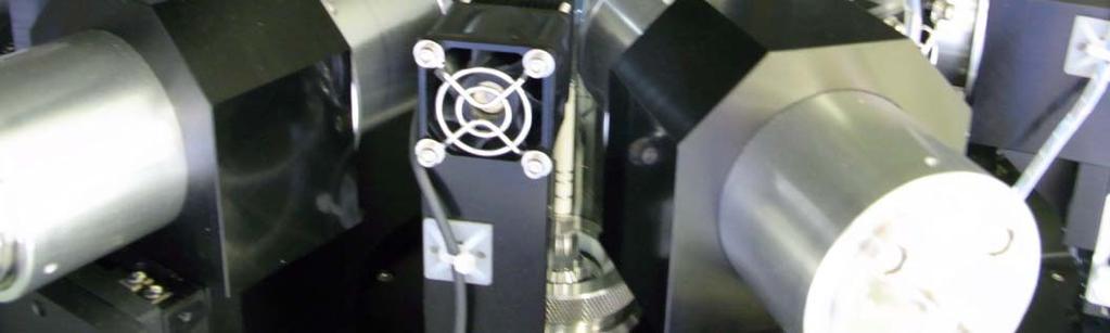
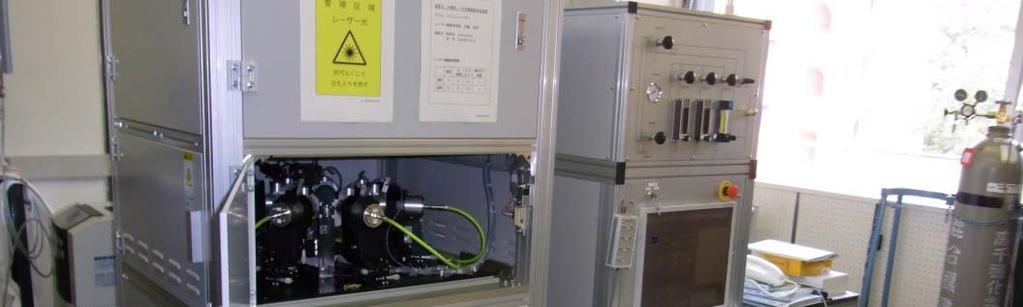
10 common valleys, indicating that total number of valleys equals to N. In the case of odd numbers, laser beams do not point to antiparallel directions and each laser beam has two valleys independently, indicating that total number of valleys equals to 2N. Such increase in the number of valleys for odd N makes the intensity pattern fine and smooth, and suppresses the decrease of intensity at the valley bottoms. It is worth to note that the intensity distribution for N = 3 coincides completely with that for N = 6 in Fig. 3. In general, the intensity distribution for the odd number N coincides with that for the even number 2N. From the discussion so far, odd number of LDs are effective to homogenize the irradiated light along the rotational direction. In addition, in the case of even number of LDs, the laser beam emitted from a LD may enter and damage the LD at the symmetric position, which also favors odd number of LDs. 5. Assembling of the LDFZ furnace Based on the simulations, we have adopted 7 LDs, which ensures the homogeneity of 97.5 %. We assembled a furnace shown in Fig. 5. The wavelength of LDs is 975 nm. Maximum power of each LD is 50 W and the maximum total power is 350 W. In order to keep the emitted laser powers of 10
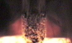
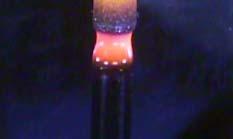
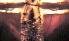
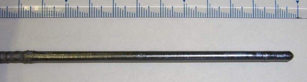
11 all the LD identical, the power of each LD is calibrated and individual power source is used to control each LD. In order to stabilize the laser power, Peltier module is used and the temperature of the LDs is kept constant within ± 0.01 K. By this system, ruby (melting point of ~2000 C) can be melted. 6. Examples of crystal growth by the LDFZ method It is well known that the crystal growth of incongruently melting BiFeO 3 by the conventional lamp-heated FZ method is difficult. (There are a few reports for the growth by the conventional FZ method [4].) Our trial by the conventional method is shown in Fig. 6 (a). Due to the gentle temperature gradient along the axial direction, the melt attacks the feed rod, which induces inhomogeneous melting and makes the growth unstable. In addition, the melt often spills over the grown crystal. There is no clear border between the molten zone and the feed rod or the grown boule. In contrast, in the case of the LDFZ method, as shown in Fig. 6 (b), the temperature gradient is steep, the interface between the liquid and the solid is clear and flat, the melt scarcely attacks the feed rod and scarcely spills over the grown crystal, and therefore long-term stable growth is realized. A grown crystal is shown in Fig. 6 (c). The details of the growth is described in ref. [5] 11
12 It is also known that the crystal growth of incongruently melting La 2-x Ba x CuO 4 by the conventional lamp-heated FZ method is difficult. (There are a few reports for the growth by the conventional method [6-8].) By the LDFZ method, as shown in Fig. 7 (a), stable crystal growth is realized and crystals with x > 1/8 are obtained. A grown crystal with a flat facet is shown in Fig. 7 (b). The details will be described elsewhere. 7. The characteristic features of the LDFZ method The features of the LDFZ method are summarized below, revealed by the actual crystal growth Focusing properties along the axial direction by the LDFZ method Homogeneous irradiation of laser beam, whose cross section mostly covers the molten zone, is realized by use of a light pipe. Typically, the vertical dimension of the molten zone equals to that of the beam multiplied by It is a great advantage for the beam size to be easily designed to fit the desired size of the molten zone. The sharp cutoff at the edge of the beam prevents the melt from attacking the feed rod and from spilling over the crystal, and makes the interface between the solid and the liquid flat and clear. Such features are useful to stabilize and reproduce the crystal growth 12
13 reasonably well. Precise temperature control of the LDs by the Peltier module contributes to the stable crystal growth as well, and does not require one to adjust the operation currents of the LDs for a period longer than a week under the optimized conditions. The temperature gradient near the interface between the solid and liquid for BiFeO 3 can be estimated here. It is likely to identify the interface between the molten zone and the feed rod as being at the eutectic point (933 C [9]), and the interface between the feed rod absorbed with the melt (the thin glittering part just above the molten zone in Fig. 6 (b)) and the feed rod without the melt as being at the peritectic point (777 C [9]). Since the distance between these two interfaces for the LDFZ method is only ~1 mm from Fig. 6 (b), the average temperature gradient of this region is estimated to be ~150 C/mm. In the case of the conventional lamp-heated FZ method, the corresponding distance is ~5 mm from Fig. 6 (a), and the average temperature gradient of this region is estimated to be ~30 C/mm. The LDFZ method satisfies efficient local heating. In the case of ruby, the total input electric power into LDs is 630 W and the total output laser power is 280 W for the LDFZ method, whereas the total input electric power is 2100 W and the total output light power is estimated to be 1900 W under the assumption that the efficiency of the halogen lamp is 90 % for the 13
14 lamp-heated FZ method. In the case of BiFeO 3, the total input electric power into LDs is 180 W and the total output laser power is 30 W for the LDFZ method, whereas the total input electric power is 190 W and the total output light power is estimated to be 170 W under the same assumption of the efficiency described above for the lamp-heated FZ method. Therefore, the output light power required for the lamp-heated FZ method is about 6 times as much as that for the LDFZ method. It suggests that most of the light power is not used to heat the molten zone directly in the case of the lamp-heated FZ method Focusing properties along the rotational direction by the LDFZ method In the case of the odd number of LDs, the intensity of the irradiated light becomes homogeneous effectively, as shown by the simulation. For the assembled furnace with N = 7, the interface between the solid and the liquid is flat, as shown in Fig. 6 (b), suggesting that the homogeneity of the heating power distribution as well as the temperature distribution along the rotational direction is realized. It is expected that such homogeneous heating would reduce defects in the grown crystals. By making the horizontal width of the homogeneous beam larger than the diameter of the sample, the crystal growth is stable even if the 14
15 misalignment of the sample or the displacement of the sample by the contact of the feed rod and the crystal occurs, displaying that the intensity of the irradiated light is unaffected. From all of these features stable crystal growth is realized. 8. Conclusions We have developed the LDFZ method optimized to the crystal growth of the incongruently melting materials. A multiple number of equivalent LDs and optics are arranged in equal intervals on a circle whose center is at the sample position. In the optics, light pipes are used to make the cross section of each laser beam rectangular and the distribution of light intensity homogeneous. The laser beams emitted from them are irradiated on the sample, which realizes homogeneous heating along the rotational direction. Odd number of laser beams are effective to homogenize irradiation. Along the axial direction, the dimension of each beam can be designed to nearly equal to the desirable vertical length of the molten zone. Such a design makes the temperature gradient at the interface between the liquid and the solid steep and prevents the melt from attacking the feed rod and from spilling over the crystal. These features enable stable crystal growth. The horizontal width of each beam is designed to be larger than the diameter of 15
16 the sample, which makes the irradiated light intensity unchanged if the misalignment or the decentering of the sample occurs. The precise temperature control of the LDs by the Peltier module ensures the stability of the irradiated light intensity. Thus we have overcome the problems in the lamp-heated FZ method. ACKNOWLEDGEMENTS This work was partly supported by JSPS Grants-in-Aid for Scientific Research (Grant Number ) and the Funding Program for World-Leading Innovative R&D on Science and Technology (FIRST Program), Japan. 16
17 REFERENCES [1] I. Tanaka, H. Kojima, Nature (London) 337 (1989) 21. [2] M. Imada, A. Fujimori, Y. Tokura, Rev. Mod. Phys. 70 (1998) [3] C.-H. Lee, N. Kaneko, S. Hosoya, K. Kurahashi, S. Wakimoto, K. Yamada, Y. Endoh, Supercond. Sci. Technol. 11 (1998) 891. [4] Z. Xu, J. Wen, T. Berlijn, P. M. Gehring, C. Stock, M. B. Stone, W. Ku, G. Gu, S. M. Shapiro, R. J. Birgeneau, G. Xu, arxiv: (2012). [5] T. Ito, T. Ushiyama, Y. Yanagisawa, R. Kumai, Y. Tomioka, Cryst. Growth Des. 11 (2011) [6] T. Ito, K. Oka, Physica C 231 (1994) 305. [7] T. Adachi, T. Noji, Y. Koike, Phys. Rev. B 64 (2001) [8] M. Fujita, H. Goka, K. Yamada, J. M. Tranquada, L. P. Regnault, Phys. Rev. B 70 (2004) [9] R. Palai, R. S. Katiyar, H. Schmid, P. Tissot, S. J. Clark, J. Robertson, S. A. T. Redfern, G. Catalan, J. F. Scott, Phys. Rev. B 77 (2008)
18 FIGURE CAPTIONS Figure 1 Schematic drawings of the light paths and the distribution of the irradiated light intensity on the sample surface for the conventional lamp-heated FZ method and the LDFZ method. To make the effects displayed clearly, the diameter of the sample is drawn larger than the actual size. (a) Vertical cross section of the conventional lamp-heated FZ method. The left half is for the point light source and the right one is for the light source with finite size such as a filament. (b) Vertical cross section of the conventional lamp-heated FZ method for the point light source, for the case that the sample position is decentered. (c) Horizontal cross section of the conventional lamp-heated FZ method for the point light source. (d) Horizontal cross section of the conventional lamp-heated FZ method for the point light source, for the case that the sample position is decentered. (e) Vertical cross section of the LDFZ method. (f) Horizontal cross section of the LDFZ method. Figure 2 A schematic perspective drawing of the LDFZ method. Homogeneous laser beams whose cross section is rectangular are irradiated. Figure 3 The simulation of one-dimensional distribution of irradiated light intensity 18
19 along the rotational direction on a cylindrical sample. Homogeneous laser beams, as shown schematically in Figs. 1 (e), 1 (f) and 2, with N = 3, 4, 5, 6, 7, and 8 are irradiated. The red dashed line is for each LD and the blue solid line is for the total of all the LDs. The intensities are plotted in arbitrary unit. Figure 4 The homogeneity, defined as the ratio of the minimal to the maximal intensities along the rotational direction, as a function of N. Figure 5 Photographs of the assembled LDFZ furnace. (a) The sample chamber and the heating elements. (b) The whole of the furnace. Figure 6 The crystal growth of BiFeO 3 (a) by the conventional lamp-heated FZ method and (b) by the LDFZ method. (c) A grown crystal by the LDFZ method. Figure 7 (a) The crystal growth and (b) a grown crystal of (La,Ba) 2 CuO 4 by the LDFZ method. 19


20 (a) (b) Fig. 1


21 (c) (d) Fig. 1


22 (e) (f) Fig. 1
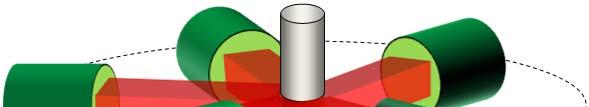
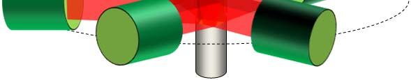
23 Fig. 2
24 (a) Intensity N = 3 x1.4 (b) Rotaional angle (degree) N = 4 x1.1 Intensity (c) Intensity Rotaional angle (degree) N = 5 x0.8 0 Fig Rotaional angle (degree) 360
25 (d) Intensity N = 6 x0.7 (e) Intensity Rotaional angle (degree) N = 7 x0.6 (f) Intensity Rotaional angle (degree) N = 8 x0.5 Fig Rotaional angle (degree) 360
26 100 Homogeneity (%) N Fig. 4

27 (a) (b) Fig. 5
 Fig.")
28 (a) (b) (c) Fig. 6


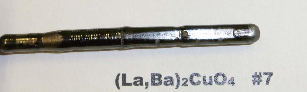
29 (a) (b) Fig. 7
Vertical Bridgman growth of sapphire Crystals with thin-neck formation process
 Vertical Bridgman growth of sapphire Crystals with thin-neck formation process K. Hoshikawa 1, T. Taishi 1, E. Ohba 1, 2, C. Miyagawa 1, 2, T. Kobayashi 2, J. Yanagisawa 2, M.Shinozuka 2 Faculty of Engineering,
In-process Monitoring and Adaptive Control during Micro Welding with CW Fiber Laser
 In-process Monitoring and Adaptive Control during Micro Welding with CW Fiber Laser Yousuke KAWAHITO*, Masaharu KAWASAKI* and Seiji KATAYAMA* * Osaka University, Joining and Welding Research Institute
In-Process Monitoring and Adaptive Control in Micro Welding with a Single-Mode Fiber Laser.
 Title Author(s) In-Process Monitoring and Adaptive Control in Micro Welding with a Single-Mode Fiber Laser KAWAHITO, Yousuke; KATAYAMA, Seiji Citation Transactions of JWRI. 38(2) P.5-P.11 Issue Date 2009-12
REVIEW OF LASER PLASTIC WELDING PROCESS
 REVIEW OF LASER PLASTIC WELDING PROCESS Kalpesh More 1, Rushikesh Aher 2, Makrand Bharaskar 3 1,2,3 Mechanical, Sandip Institute Technology and Research Centre/Pune University, (India) ABSTRACT There are
Evaluation of Effects of Stirring in a Melting Furnace for Aluminum
 Temperature ( ) Evaluation of Effects of Stirring in a Melting Furnace for Aluminum Kunio Matsuzaki 1,Toru Shimizu 1, Yoichi Murakoshi 1 and Kenzo Takahashi 2 1 Japanese National Institute of Advanced
EXPERIMENTAL INVESTIGATION ON COOLING RATE FOR CENTRIFUGAL CASTING Kirti Kanaujiya, Yugesh Mani Tiwari Department of Mechanical Engineering
 ISSN 2320-9135 1 International Journal of Advance Research, IJOAR.org Volume 3, Issue 9, September 2015, Online: ISSN 2320-9135 EXPERIMENTAL INVESTIGATION ON COOLING RATE FOR CENTRIFUGAL CASTING Kirti
Evaluation of 4 Fe-doped InP wafers using a scanning photoluminescence technique
 Evaluation of 4 Fe-doped InP wafers using a scanning photoluminescence technique M Fukuzawa, M Suzuki and M Yamada Presented at the 8th International Conference on Electronic Materials (IUMRS-ICEM 2002,
Figure 2.3 (cont., p. 60) (e) Block diagram of Pentium 4 processor with 42 million transistors (2000). [Courtesy Intel Corporation.
 (e) Block diagram of Pentium 4 processor with 42 million transistors (2000). [Courtesy Intel Corporation.") Figure 2.1 (p. 58) Basic fabrication steps in the silicon planar process: (a) oxide formation, (b) selective oxide removal, (c) deposition of dopant atoms on wafer, (d) diffusion of dopant atoms into exposed
Figure 2.1 (p. 58) Basic fabrication steps in the silicon planar process: (a) oxide formation, (b) selective oxide removal, (c) deposition of dopant atoms on wafer, (d) diffusion of dopant atoms into exposed
1. Introduction. 2. COMD Mechanisms. COMD Behavior of Semiconductor Laser Diodes. Ulrich Martin
 COMD Behavior of Semiconductor Laser Diodes 39 COMD Behavior of Semiconductor Laser Diodes Ulrich Martin The lifetime of semiconductor laser diodes is reduced by facet degradation and catastrophical optical
Laser transformation hardening on rod-shaped carbon steel by Gaussian beam
 Laser transformation hardening on rod-shaped carbon steel by Gaussian beam Jong-Do KIM 1, Myeong-Hoon LEE 1, Su-Jin LEE 2, Woon-Ju KANG 2 1. Division of Marine System Engineering, College of Maritime Sciences,
11.3 The analysis of electron diffraction patterns
 11.3 The analysis of electron diffraction patterns 277 diameter) Ewald reflecting sphere, the extension of the reciprocal lattice nodes and the slight buckling of the thin foil specimens all of which serve
Experiment 2b X-Ray Diffraction* Optical Diffraction Experiments
 * Experiment 2b X-Ray Diffraction* Adapted from Teaching General Chemistry: A Materials Science Companion by A. B. Ellis et al.: ACS, Washington, DC (1993). Introduction Inorganic chemists, physicists,
In-Process Monitoring and Adaptive Control during Pulsed YAG Laser Spot Welding of Aluminum Alloy Thin Sheets
 JLMN-Journal of Laser Micro/Nanoengineering, Vol.1, No. 1, 2006 In-Process Monitoring and Adaptive Control during Pulsed YAG Laser Spot Welding of Aluminum Alloy Thin Sheets Yousuke KAWAHITO * and Seiji
BONDING OF MULTIPLE WAFERS FOR HIGH THROUGHPUT LED PRODUCTION. S. Sood and A. Wong
 10.1149/1.2982882 The Electrochemical Society BONDING OF MULTIPLE WAFERS FOR HIGH THROUGHPUT LED PRODUCTION S. Sood and A. Wong Wafer Bonder Division, SUSS MicroTec Inc., 228 SUSS Drive, Waterbury Center,
High Power Operation of Cryogenic Yb:YAG. K. F. Wall, B. Pati, and P. F. Moulton Photonics West 2007 San Jose, CA January 23, 2007
 High Power Operation of Cryogenic Yb:YAG K. F. Wall, B. Pati, and P. F. Moulton Photonics West 2007 San Jose, CA January 23, 2007 Outline Early work on cryogenic lasers MPS laser technology Recent program
Analysis on Viscous Flow of VAD Silica Glass During Heat Forming
 INDUSTRIAL MATERIALS Analysis on Viscous Flow of VAD Silica Glass During Heat Forming Tomoyuki YOKOKAWA*, Tadashi ENOMOTO, Takashi YAMAZAKI, Kazuya KUWAHARA, Masaru FURUSHOU and Ken MANABE Silica glass
Additive Element Effects on Electronic Conductivity of Zirconium Oxide Film
 Journal of NUCLEAR SCIENCE and TECHNOLOGY, 31[6], pp. 546~551 (June 1994). Additive Element Effects on Electronic Conductivity of Zirconium Oxide Film Yusuke ISOBE, Motomasa FUSE and Kinya KOBAYASHI Energy
Types of Foundations
 Shallow Foundations Types of Foundations Foundations can be classified to two major categories: Shallow. Deep. 1 Introduction If the soil stratum is suitable for supporting the structural loads from the
Electronically switchable diffractive optical elements
 Electronically switchable diffractive optical elements GARRY LESTER, ADRIAN STRUDWICK AND * STEPHEN COULSTON L-lectronics Ltd, 48 Wilton Way, Exeter, EX 3UR * QuantX (Oxford), North Leigh Business Park,
Surface Characterization of Laser Polished Indirect-SLS Parts
 Surface Characterization of Laser Polished Indirect-SLS Parts Jorge A. Ramos, David L. Bourell, Joseph J. Beaman Laboratory for Freeform Fabrication The University of Texas at Austin, Austin, Texas 78712
Splat formation in plasma-spray coating process*
 Pure Appl. Chem., Vol. 74, No. 3, pp. 441 445, 2002. 2002 IUPAC Splat formation in plasma-spray coating process* Javad Mostaghimi and Sanjeev Chandra Centre for Advanced Coating Technologies, University
Titanium Welding Technology
 UDC 669. 295 : 621. 791. 754 Titanium Welding Technology Tadayuki OTANI* 1 Abstract In order to establish titanium welding technology TIG arc weldability and MIG arc weldability were surveyed. For TIG
Module 3 Selection of Manufacturing Processes. IIT Bombay
 Module 3 Selection of Manufacturing Processes Lecture 3 Design for Bulk Deformation Processes Instructional objectives By the end of this lecture, the students are expected to learn the working principle
MELT POOL GEOMETRY SIMULATIONS FOR POWDER-BASED ELECTRON BEAM ADDITIVE MANUFACTURING. Bo Cheng and Kevin Chou
 MELT POOL GEOMETRY SIMULATIONS FOR POWDER-BASED ELECTRON BEAM ADDITIVE MANUFACTURING Bo Cheng and Kevin Chou Mechanical Engineering Department The University of Alabama Tuscaloosa, AL 35487 Accepted August
Excimer Laser Annealing of Hydrogen Modulation Doped a-si Film
 Materials Transactions, Vol. 48, No. 5 (27) pp. 975 to 979 #27 The Japan Institute of Metals Excimer Laser Annealing of Hydrogen Modulation Doped a-si Film Akira Heya 1, Naoto Matsuo 1, Tadashi Serikawa
Behavior and Strength of Slab-Edge Beam-Column Connections under Shear Force and Moment
 Behavior and Strength of Slab-Edge Beam-Column Connections under Shear Force and Moment Omar M. Ben-Sasi Abstract A total of fourteen slab-edge beam-column connection specimens were tested gradually to
CHAPTER 9 PHASE DIAGRAMS
 CHAPTER 9 PHASE DIAGRAMS PROBLEM SOLUTIONS 9.14 Determine the relative amounts (in terms of mass fractions) of the phases for the alloys and temperatures given in Problem 9.8. 9.8. This problem asks that
300mm Wafer Stain Formation by Spin Etching
 10.1149/1.2980313 The Electrochemical Society 300mm Wafer Stain Formation by Spin Etching K. Sato a, S. Mashimoto a, and M. Watanabe a a Process Development, SEZ Japan, Inc., Hongo, Bunkyo-ku 1130033,
Ceramic and glass technology
 29 Glass Properties Glass is an inorganic, nonmetallic material which cools to a rigid solid without crystallization. Glassy, or noncrystalline, materials do not solidify in the same sense as do those
Electromagnetic Casting Technique for Slab Casting
 Technical Report UDC 621. 746. 047 : 539 : 072 Electromagnetic Casting Technique for Slab Casting Masahiro TANI* Takehiko TOH Kenji UMETSU Kazuhisa TANAKA Masafumi ZEZE Keiji TSUNENARI Kazunori HAYASHI
Manufacturing of fibre preforms with granulated oxides: Influence of the grain size
 PART III 1 Manufacturing of fibre preforms with granulated oxides: Influence of the grain size R. Scheidegger, L. Di Labio, W. Lüthy, T. Feurer Institute of Applied Physics, University of Bern, Sidlerstrasse
MODELING OF LASER BASED DIRECT METAL DEPOSITION PROCESS
 MODELING OF LASER BASED DIRECT METAL DEPOSITION PROCESS Jayanth N PG Student PSG College of Technology jayanthnagaraj@gmail.com Ravi K R Associate Professor PSG College of Technology Krravi.psgias@gmail.com
350 C for 8 hours in argon atmosphere. Supplementary Figures. Supplementary Figure 1 High-temperature annealing of BP flakes on SiO 2.
 Supplementary Figures Supplementary Figure 1 High-temperature annealing of BP flakes on SiO 2. (a-d) The optical images of three BP flakes on a SiO 2 substrate before (a,b) and after annealing (c,d) at
Computer Simulation of Forging Using the Slab Method Analysis
 International Journal of Scientific & Engineering Research Volume 2, Issue 6, June-2011 1 Computer Simulation of Forging Using the Slab Method Analysis S. B. Mehta, D. B. Gohil Abstract Forging is a very
Sapphire Crystal Growth
 Lehrstuhl Werkstoffe der Elektrotechnik Sapphire Crystal Growth Matthias Bickermann Vortrag auf der WET-Klausurtagung in Silberbach/Selb, 14. 16. Februar 2008 Lehrstuhl Werkstoffe der Elektrotechnik (WW6),
Characterization of laser-material interaction during laser cladding process P.-A. Vetter,* J. Fontaine,* T. Engel," L. Lagrange,& T.
 Characterization of laser-material interaction during laser cladding process P.-A. Vetter,* J. Fontaine,* T. Engel," L. Lagrange,& T. Marchione^ f^, BID de /a rzcfozre ^7000 France ABSTRACT The interaction
Optical Coatings. Photonics 4 Luxury Coatings , Genève. Dr. Andreas Bächli Head of Optical Coatings at RhySearch, Buchs (SG)
") Optical Coatings Photonics 4 Luxury Coatings 21.06.2017, Genève Dr. Andreas Bächli Head of Optical Coatings at RhySearch, Buchs (SG) RhySearch The Research- and Innovation Center in the Rhine Valley RhySearch
Optical Coatings Photonics 4 Luxury Coatings 21.06.2017, Genève Dr. Andreas Bächli Head of Optical Coatings at RhySearch, Buchs (SG) RhySearch The Research- and Innovation Center in the Rhine Valley RhySearch
Fig1: Melt pool size of LAMP vs. µlamp. The LAMP process s melt pool is x the area of the LAMP s melt pool.
 Proceedings of the 4th Annual ISC Research Symposium ISCRS 2010 April 21, 2010, Rolla, Missouri LOW COST IMAGING OF MELTPOOL IN MICRO LASER AIDED MANUFACTURING PROCESS (µlamp) ABSTRACT This paper describes
Simulating Plasmon Effect in Nanostructured OLED Cathode Using COMSOL Multiphysics
 Simulating Plasmon Effect in Nanostructured OLED Cathode Using COMSOL Multiphysics Leiming Wang *, Jun Amano, and Po-Chieh Hung Konica Minolta Laboratory USA Inc. *Corresponding author: 2855 Campus Drive
Thin AC-PDP Vacuum In-line Sealing Using Direct-Joint Packaging Method
 H128 0013-4651/2004/151 5 /H128/5/$7.00 The Electrochemical Society, Inc. Thin AC-PDP Vacuum In-line Sealing Using Direct-Joint Packaging Method Duck-Jung Lee, a,b,z Seung-IL Moon, a Yun-Hi Lee, c and
Chapter 12. Flux Cored Arc Welding Equipment, Setup, and Operation Delmar, Cengage Learning
 Chapter 12 Flux Cored Arc Welding Equipment, Setup, and Operation Objectives Explain the FCA welding process Describe what equipment is needed for FCA welding List the advantages of FCA welding, and explain
Standard Optics Information
 INFRASIL 301, 302 1. GENERAL PRODUCT DESCRIPTION Heraeus INFRASIL 301 and 302 are optical quartz glass grades manufactured by fusion of natural quartz crystals in an electrically heated furnace. They combine
Visualization and Control of Particulate Contamination Phenomena in a Plasma Enhanced CVD Reactor
 Visualization and Control of Particulate Contamination Phenomena in a Plasma Enhanced CVD Reactor Manabu Shimada, 1 Kikuo Okuyama, 1 Yutaka Hayashi, 1 Heru Setyawan, 2 and Nobuki Kashihara 2 1 Department
Universität Hamburg, Hamburg, Germany. Universität Hamburg, Hamburg, Germany
 Sample Preparation, Micromagnetic Simulations, Circular-Rotational Currents, Parasitic Oersted Fields and Clover Samples (Magnetic Antivortex-Core Reversal by Circular-Rotational Spin Currents) Thomas
Commonwealth of Pennsylvania PA Test Method No. 614 Department of Transportation October Pages LABORATORY TESTING SECTION. Method of Test for
 Commonwealth of Pennsylvania PA Test Method No. 614 Department of Transportation 6 Pages LABORATORY TESTING SECTION Method of Test for MEASURING THE LENGTH OF DRILLED CONCRETE CORES 1. SCOPE 1.1 This method
Chapter 15 Extrusion and Drawing of Metals
 Introduction Chapter 15 Extrusion and Drawing of Metals Alexandra Schönning, Ph.D. Mechanical Engineering University of North Florida Figures by Manufacturing Engineering and Technology Kalpakijan and
Continuous Rheocasting for Aluminum-Copper Alloys
 Materials Transactions, Vol. 43, No. 9 (2002) pp. 2285 to 2291 c 2002 The Japan Institute of Metals Continuous Rheocasting for Aluminum-Copper Alloys Kiyoshi Ichikawa, Masahito Katoh and Fumio Asuke Ecology-Oriented
Multi-seeded melt growth (MSMG) of bulk Y-Ba-Cu-O using thin-film seeds
 of bulk Y-Ba-Cu-O using thin-film seeds") Multi-seeded melt growth (MSMG) of bulk Y-Ba-Cu-O using thin-film seeds T. Y. Li 1, C. L. Wang 1, L. J. Sun 1, S. B. Yan 1, L. Cheng 1, and X. Yao 1, 2, a), 1 Department of Physics, Key Laboratory of Artificial
Multi-seeded melt growth (MSMG) of bulk Y-Ba-Cu-O using thin-film seeds T. Y. Li 1, C. L. Wang 1, L. J. Sun 1, S. B. Yan 1, L. Cheng 1, and X. Yao 1, 2, a), 1 Department of Physics, Key Laboratory of Artificial
Diode laser beam absorption in laser transformation hardening of low alloy steel
 Diode laser beam absorption in laser transformation hardening of low alloy steel Henrikki Pantsar and Veli Kujanpää Citation: Journal of Laser Applications 16, 147 (2004); doi: 10.2351/1.1710879 View online:
Design for Forging. Forging processes. Typical characteristics and applications
 Design for Forging Forging processes Forging is a controlled plastic deformation process in which the work material is compressed between two dies using either impact or gradual pressure to form the part.
APN029. The SER2 Universal platform for material testing. A.Franck TA Instruments Germany
 APN029 The SER2 Universal platform for material testing A.Franck TA Instruments Germany Keywords: Elongation viscosity, Hencky rate, SER, friction testing INTRODUCTION The roots of extensional rheometry
Glass Processing Course
 Glass Processing Course Lecture 4. COLOR IN COMMERCIAL GLASSES JAMES E. SHELBY Professor Emeritus Alfred University shelbyje@alfred.edu Spring 2015 An Online-learning resource from the IMI-NFG Lecture
Joints / Fixed Joints
 Autodesk Inventor Engineer s Handbook هندبوک مهندسی نرم افزار Autodesk Inventor انجمن اینونتور ایران www.irinventor.com Email: irinventor@chmail.ir irinventor@hotmail.com Tel: 09352191813 & Joints / Fixed
THE USE OF LIGHT PIPES FOR DEEP PLAN OFFICE BUILDINGS A case study of Ken Yeang's bioclimatic skyscraper proposal for KLCC, Malaysia
 THE USE OF LIGHT PIPES FOR DEEP PLAN OFFICE BUILDINGS A case study of Ken Yeang's bioclimatic skyscraper proposal for KLCC, Malaysia Veronica Garcia Hansen*, Ian Edmonds**, Richard Hyde*** *School of Design
Preview of LEAME Computer Software
 Appendix Preview of LEAME Computer Software Thus far, this book has focused on the fundamental principles and methods for analyzing slope stability using the limit equilibrium method. The computer software
Vibration influence on structure and density of aluminum alloys
 IOP Conference Series: Materials Science and Engineering PAPER OPEN ACCESS Vibration influence on structure and density of aluminum alloys To cite this article: A A Usoltsev et al 2016 IOP Conf. Ser.:
A Survey of Laser Types. Gas Lasers
 Mihail Pivtoraiko Andrei Rozhkov Applied Optics Winter 2003 A Survey of Laser Types Laser technology is available to us since 1960 s, and since then has been quite well developed. Currently, there is a
Laser Welding of Engineering Plastics
 Laser Welding of Engineering Plastics Technical Information Further information on individual products: www.ultramid.de www.ultradur-lux.basf.com www.ultrason.de www.plasticsportal.eu/ultraform 2 LASER
PULSED LASER WELDING
 PULSED LASER WELDING Girish P. Kelkar, Ph.D. Girish Kelkar, Ph.D, WJM Technologies, Cerritos, CA 90703, USA Laser welding is finding growing acceptance in field of manufacturing as price of lasers have
Specimen Preparation Technique for a Microstructure Analysis Using the Focused Ion Beam Process
 Specimen Preparation Technique for a Microstructure Analysis Using the Focused Ion Beam Process by Kozue Yabusaki * and Hirokazu Sasaki * In recent years the FIB technique has been widely used for specimen
Inducement of superconductivity in Fe(Te,S) by sulfuric acid treatment
 by sulfuric acid treatment") Inducement of superconductivity in Fe(Te,S) by sulfuric acid treatment Masanori NAGAO *, Yoshikazu MIZUGUCHI 1, Keita DEGUCHI 2, Satoshi WATAUCHI, Isao TANAKA and Yoshihiko TAKANO 2 University of Yamanashi,
Inducement of superconductivity in Fe(Te,S) by sulfuric acid treatment Masanori NAGAO *, Yoshikazu MIZUGUCHI 1, Keita DEGUCHI 2, Satoshi WATAUCHI, Isao TANAKA and Yoshihiko TAKANO 2 University of Yamanashi,
FEASIBILITY OF BUILDING AN OVERHANG STRUCTURE USING DIRECT METAL DEPOSITION
 Proceedings of the 5th Annual ISC Research Symposium ISCRS 2011 April 7, 2011, Rolla, Missouri FEASIBILITY OF BUILDING AN OVERHANG STRUCTURE USING DIRECT METAL DEPOSITION Sriram Prabhu Department Of Manufacturing
Transparent Ceramic Yb 3+ :Lu2O3 Materials
 Contract no.: FA2386-10-1-4113 Final report for the project on: Transparent Ceramic Yb 3+ :Lu2O3 Materials Submission Date: Jan 19 th, 2012 Principal Investigator: Dr. Akio Ikesue World-Lab. Co., Ltd.
Scanning space analysis in Selective Laser Melting for CoCrMo powder
 Available online at www.sciencedirect.com ScienceDirect Procedia Engineering 63 ( 213 ) 37 378 The Manufacturing Engineering Society International Conference, MESIC 213 Scanning space analysis in Selective
Chapter 10, Phase Transformations
 Chapter Outline: Phase Transformations Heat Treatment (time and temperature) Microstructure Kinetics of phase transformations Homogeneous and heterogeneous nucleation Growth, rate of the phase transformation
Computation and analysis of temperature distribution in the crosssection
 Computation and analysis of temperature distribution in the crosssection of the weld Vee John Inge Asperheim, Bjørnar Grande, Leif Markegård, ELVA Induksjon a.s James E. Buser, ELVA Induction inc. Patrick
FREEZING AND THAWING TESTS OF COMPACTED SOIL-CEMENT MIXTURE
 Test Procedure for FREEZING AND THAWING TESTS OF COMPACTED SOIL-CEMENT TxDOT Designation: Tex-135-E Effective Date: August 1999 1. SCOPE 1.1 This method determines the soil-cement losses, moisture changes,
Design of a new concentrated photovoltaic system under UAE conditions
 Design of a new concentrated photovoltaic system under UAE conditions Ahmed Amine Hachicha, and Muahammad Tawalbeh Citation: AIP Conference Proceedings 1850, 110004 (2017); View online: https://doi.org/10.1063/1.4984478
Online Student Guide Types of Control Charts
 Online Student Guide Types of Control Charts OpusWorks 2016, All Rights Reserved 1 Table of Contents LEARNING OBJECTIVES... 4 INTRODUCTION... 4 DETECTION VS. PREVENTION... 5 CONTROL CHART UTILIZATION...
Thermal Performance of Thermoelectric Cooler (TEC) Integrated Heat Sink and Optimizing Structure for Low Acoustic Noise / Power Consumption
 Integrated Heat Sink and Optimizing Structure for Low Acoustic Noise / Power Consumption") Thermal Performance of Thermoelectric Cooler () Integrated Heat Sink and Optimizing Structure for Low Acoustic Noise / Power Consumption Masami Ikeda, Toshiaki Nakamura, Yuichi Kimura, Hajime Noda The
Thermal Performance of Thermoelectric Cooler () Integrated Heat Sink and Optimizing Structure for Low Acoustic Noise / Power Consumption Masami Ikeda, Toshiaki Nakamura, Yuichi Kimura, Hajime Noda The
Reduction of Micro-Cracks in Large Diameter In x Ga 1-x Sb Bulk Crystals
 Mat. Res. Soc. Symp. Proc. Vol. 763 2003 Materials Research Society B8.28.1 Reduction of Micro-Cracks in Large Diameter In x Ga 1-x Sb Bulk Crystals Juliet Vogel * and Partha S. Dutta ** * Department of
In-Situ Characterization During MOVPE Growth of III-Nitrides using Reflectrometry
 18 Annual Report 1999, Dept. of Optoelectronics, University of Ulm In-Situ Characterization During MOVPE Growth of III-Nitrides using Reflectrometry Christoph Kirchner and Matthias Seyboth The suitability
ELECTRICAL RESISTIVITY AS A FUNCTION OF TEMPERATURE
 ELECTRICAL RESISTIVITY AS A FUNCTION OF TEMPERATURE Introduction The ability of materials to conduct electric charge gives us the means to invent an amazing array of electrical and electronic devices,
Hybrid atomization method suitable for production of fine spherical lead-free solder powder
 NUKLEONIKA 2006;51(Supplement 1):S83 S88 PROCEEDINGS Hybrid atomization method suitable for production of fine spherical lead-free solder powder Kazumi Minagawa, Hideki Kakisawa, Susumu Takamori, Yoshiaki
11.3 Polishing with Laser Radiation
 196 E. Willenborg 11.3 Polishing with Laser Radiation Edgar Willenborg The surface roughness of a part or product strongly influences its properties and functions. Among these can be counted abrasion and
Introduction. 1. Outline of fan case ring
 A near-net-shape (NNS) ring-rolling process was developed to reduce the forging weight of a rolled, fan case front, ring made of Ti-6Al-4V. This was achieved by optimizing the ring-rolling process in which
LD21 NEW MATERIALS FOR LARGE-CALIBER ROTATING BANDS FOR HIGH CHARGES. M. Schupfer1, K. Steinhoff2, R. Röthlisberger1 1.
 LD21 19th International Symposium of Ballistics, 7 11 May 2001, Interlaken, Switzerland NEW MATERIALS FOR LARGE-CALIBER ROTATING BANDS FOR HIGH CHARGES M. Schupfer1, K. Steinhoff2, R. Röthlisberger1 1
Index. Cambridge University Press Introduction to Elasticity Theory for Crystal Defects R. W. Balluffi. Index.
 Airy stress functions formulation of 60 1 table of 426 alternator operator 419 Brown s formula 255 Burgers equation 264 5 Christoffel stiffness tensor 34 corresponding elastic fields 25 7 curvature tensor,
Thermal Evaporation. Theory
 Thermal Evaporation Theory 1. Introduction Procedures for depositing films are a very important set of processes since all of the layers above the surface of the wafer must be deposited. We can classify
Steric Effects on the. Transition in YH x
 Steric Effects on the Metallic-Mirror Mirror to Transparent-Insulator Transition in YH x Troy C. Messina Department of Physics University of Texas at Austin Final Defense 22 November 2002 Outline Introduction
Design & Fabrication of a High-Voltage Photovoltaic Cell. Jennifer Felder
 SLAC-TN-12-021 Design & Fabrication of a High-Voltage Photovoltaic Cell Jennifer Felder Office of Science, Science Undergraduate Laboratory Internship (SULI) North Carolina State University SLAC National
Laser damage threshold of AR coatings on phosphate glass
 Laser damage threshold of AR coatings on phosphate glass Optical Coatings for Laser Applications Wednesday, 12 th April 2017, Buchs SG, Switzerland dirk.apitz@schott.com, SCHOTT Suisse SA, Advanced Optics,
The effect of ion milling on the morphology of ramp-type Josephson junctions
 Journal of MATERIALS RESEARCH Welcome Comments Help The effect of ion milling on the morphology of ramp-type Josephson junctions Dave H. A. Blank and Horst Rogalla Low Temperature Division, Department
1. Introduction. What is implantation? Advantages
 Ion implantation Contents 1. Introduction 2. Ion range 3. implantation profiles 4. ion channeling 5. ion implantation-induced damage 6. annealing behavior of the damage 7. process consideration 8. comparison
Electrical Properties of Ultra Shallow p Junction on n type Si Wafer Using Decaborane Ion Implantation
 Mat. Res. Soc. Symp. Proc. Vol. 686 2002 Materials Research Society Electrical Properties of Ultra Shallow p Junction on n type Si Wafer Using Decaborane Ion Implantation Jae-Hoon Song, Duck-Kyun Choi
Effect of Sheet Thickness and Type of Alloys on the Springback Phenomenon for Cylindrical Die
 AMERICAN JOURNAL OF SCIENTIFIC AND INDUSTRIAL RESEARCH 01, Science Huβ, http://www.scihub.org/ajsir ISSN: 153-69X, doi:10.551/ajsir.01.3.6.80.86 Effect of Sheet Thickness and Type of Alloys on the Springback
This is an electronic reprint of the original article. This reprint may differ from the original in pagination and typographic detail.
 This is an electronic reprint of the original article. This reprint may differ from the original in pagination and typographic detail. Author(s): Agar, David; Korppi-Tommola, Jouko Title: Standard testing
RAPID DESIGN AND MANUFACTURE OF ULTRALIGHT CELLULAR MATERIALS
 RAPID DESIGN AND MANUFACTURE OF ULTRALIGHT CELLULAR MATERIALS W. Brooks*, C. Sutcliffe, W. Cantwell, P. Fox, J. Todd, R. Mines. Manufacturing Science and Engineering Research Centre The University of Liverpool
Cladding in the Field of Industrial Applications
 Cladding in the Field of Industrial Applications Repair work with orbital welding equipment. Repair welding on the primary circuit of a nuclear power plant: a branch pipe is reconditioned by internal cladding
Measurement of Residual Stress by X-ray Diffraction
 Measurement of Residual Stress by X-ray Diffraction C-563 Overview Definitions Origin Methods of determination of residual stresses Method of X-ray diffraction (details) References End Stress and Strain
MEASURING THE DYNAMIC TWISTING BEHAVIOUR OF SAW BLADES IN THE KERF DURING THE SAWING PROCESS
 Journal of Machine Engineering, Vol. 16, No. 3, 2016 Received: 12 January 2016 / Accepted: 23 March 2016 / Published online: 20 June 2016 band saw, cutting, vibration, measurement Daniel ALBRECHT 1* Thomas
Diffraction: Powder Method
 Diffraction: Powder Method Diffraction Methods Diffraction can occur whenever Bragg s law λ = d sin θ is satisfied. With monochromatic x-rays and arbitrary setting of a single crystal in a beam generally
Preliminary Studies on In Situ Monitoring of Lactose Crystallization Using Focused Beam Reflectance Measurement
 Dairy Research 214 Preliminary Studies on In Situ Monitoring of Lactose Crystallization Using Focused Beam Reflectance Measurement K. Pandalaneni, J.K. Amamcharla Summary Isothermal crystallization of
a. 50% fine pearlite, 12.5% bainite, 37.5% martensite. 590 C for 5 seconds, 350 C for 50 seconds, cool to room temperature.
 Final Exam Wednesday, March 21, noon to 3:00 pm (160 points total) 1. TTT Diagrams A U.S. steel producer has four quench baths, used to quench plates of eutectoid steel to 700 C, 590 C, 350 C, and 22 C
P.S. Dutta Introduction
 1 12 Crystal-Growth Technology for Ternary III-V Semiconductor Production by Vertical Bridgman and Vertical Gradient Freezing Methods with Accelerated Crucible Rotation Technique P.S. Dutta 12.1 Introduction
Simulation of High Pressure Die Casting (HPDC) via STAR-Cast
 via STAR-Cast") Simulation of High Pressure Die Casting (HPDC) via STAR-Cast STAR Global Conf. 2012, 19-21 March, Noordwijk Romuald Laqua, Access e.v., Aachen High Pressure Die Casting: Machines and Products Common Materials:
Simulation of High Pressure Die Casting (HPDC) via STAR-Cast STAR Global Conf. 2012, 19-21 March, Noordwijk Romuald Laqua, Access e.v., Aachen High Pressure Die Casting: Machines and Products Common Materials:
A STUDY OF DAYLIGHTING TECHNIQUES AND THEIR ENERGY IMPLICATIONS USING A DESIGNER FRIENDLY SIMULATION SOFTWARE
 A STUDY OF DAYLIGHTING TECHNIQUES AND THEIR ENERGY IMPLICATIONS USING A DESIGNER FRIENDLY SIMULATION SOFTWARE Amarpreet Sethi College of Architecture and Environmental Design Arizona State University,
Aluminum / Copper oscillation welding with a 500 W direct diode laser
 Application Note Issued: 2016-06-01 Aluminum / Copper oscillation welding with a 500 W direct diode laser SUMMARY The performance of the 500 W DirectProcess direct diode laser for oscillating welding by
Growth of YBa 2 Cu 3 O 7 Films with [110] Tilt of CuO Planes to Surface on SrTiO 3 Crystals
![Growth of YBa 2 Cu 3 O 7 Films with [110] Tilt of CuO Planes to Surface on SrTiO 3 Crystals](/thumbs/72/67895252.jpg "Growth of YBa 2 Cu 3 O 7 Films with [110] Tilt of CuO Planes to Surface on SrTiO 3 Crystals") ISSN 163-7745, Crystallography Reports, 213, Vol. 58, No. 3, pp. 488 492. Pleiades Publishing, Inc., 213. Original Russian Text E.A. Stepantsov, F. Lombardi, D. Winkler, 213, published in Kristallografiya,
ISSN 163-7745, Crystallography Reports, 213, Vol. 58, No. 3, pp. 488 492. Pleiades Publishing, Inc., 213. Original Russian Text E.A. Stepantsov, F. Lombardi, D. Winkler, 213, published in Kristallografiya,
Understanding Optical Coatings For Military Applications
 Understanding Optical Coatings For Military Applications By Trey Turner, Chief Technology Officer, REO Virtually all optical components used in military applications, such as target designation, rangefinding