aquatherm blue aquatherm state of the pipe Pipe system made of polypropylene for chilled, hot fluid and various industrial applications
|
|
|
- Helen Gardner
- 6 years ago
- Views:
Transcription
1 Edition: aquatherm blue Pipe system made of polypropylene for chilled, hot fluid and various industrial applications aquatherm state of the pipe
2 New since the last VERSION E10050 aquatherm blue pipe Page Change 47 The preparation for the fusion was added. 60 The text concerning the electrofusion-socket welding has been adjusted: Cut the pipes to be welded, peel, clean and dry thoroughly with a lint-free cloth or paper. Clean the electrofusion socket s inner surface with a lint-free cloth or paper. Remove moisture that may occur immediately before the welding process again. 58 The illustration of the tightening method of flange connections was simplified. 61 The text concerning the electrofusion-socket welding has been adjusted: Pipes and fittings must be welded stress-free. 89 The loss coefficient ( z-value ) for the valves, the ball valve and the drain valve was added on this page. from 113 The article list was updated. Our sales and delivery conditions (January 2014) and the contacts of our technical sales and distribution see on our homepage Subject to technical alterations, errors and misprints excepted. With the edition of this catalogue, all former ones become void.

3 Dear customers and partners, thank you for your interest in our family enterprise. For a long time the classification of enterprises as a family has rather been hidden than actively marketed. Only in recent years family enterprises experience a comeback. From employee perspective, they are generally a flat hierarchy, provide independent and responsible work under a cooperative management style, but above all they are considered safe employers who commit permanently to their employees. By definition, family enterprises are distinguished primarily by the unity of ownership and management in the hands of a family; this criterion the aquatherm group still meets after the transition from the first to the second generation (pictured above). Our self-image of a family enterprise, however, clearly exceeds this description. Our claim describes a proactive organization that bases in the responsible contact in everyday life, that challenges encouraging, thereby accompanies developments in a promoting way and sets on a personal influenced by nearby corporate culture. If these business properties meet determined people that daily inspire through initiative, diligence and passion, until we speak of a living family enterprise, until we speak with pride of the aquatherm family. We look forward to presenting you on the following pages some insight into our colorful, slightly green-tinted aquatherm world. Christof Rosenberg Managing Director Dirk Rosenberg Managing Director 1973 Founding of aquatherm by Gerhard Rosenberg 1978 Transfer to the first factory in Biggen / D-Attendorn 1985 Completion of factory 1 in Biggen / D-Attendorn 1992 Founding of the branch in Radeberg near D-Dresden 1996 Founding of the metal processing company aquatherm metal, D-Attendorn 1998 Founding of a subsidiary in Carrara / Italy 1999 Completion of the main site in D-Attendorn as one complex (Factories 1+2, Production and Store, Laboratory and Training Centre) 2001 Completion of the extension Factory 2 in D-Attendorn 2001 Opening of the new training centre in D-Radeberg 2002 Completion of the logistics centre in D-Attendorn 2003 Completion of rebuilding and finishing of the training centre in D-Attendorn year celebration of the company aquatherm 2005 Adding of 2 storeys on the administration building 2005/06 Completion of the 4-storey hall on the premises in Attendorn Basement: Store Ground floor: Assembly / Packing 1st Floor: Laboratory and Technical department 2 nd Floor: Special manifold construction 2008 Aquisition of the former storehouse of the forwarding agent Kost, which also accomodates the room of the plant maintenace Opening of the new expertise centre for technical application year celebration of the company aquatherm Maik Rosenberg Managing Director Gerhard Rosenberg President of the Advisory Board
4 Service SERVICE TECHNICAL HOTLINE +49 (0) { { Parent plant Attendorn aquatherm GmbH Biggen 5 D Attendorn Phone: +49 (0) Fax: +49 (0) Subsidiary Radeberg aquatherm GmbH Wilhelm-Rönsch-Str. 4 D Radeberg Phone: +49 (0) Fax: +49 (0) Field staff In addition to the regular training service at Attendorn and Radeberg aquatherm field staff are available to assist customers, on site, throughout Germany. Training service In addition to training service through the merchant network aquatherm offers its customers training, free of charge, at its training centres at Attendorn and Radeberg. Fair aquatherm is represented on all important fairs relevant for the sanitary and heating sector in Germany or abroad with its own exhibition booth. For more information regarding fairs near to you, please visit internet page: 4
5 Service Certifications in accordance with ISO 9001, & Since 1996 aquatherm has been meeting the requirements of the certifiable quality management system according to DIN ISO The 2012 TÜV certificate was extended by the environmental management system according to ISO and currently by the energy management system according to ISO This success is a great contribution and represents a further step to strengthen our competitive position and to meet the high requirements and the responsiblity for our customers, partners and the environment. Laboratory The aquatherm laboratory: from the testing of granulate through to the finished product the customer can be assured of only the highest quality products. Software-Service The aquatherm - software service provides Datanorm-files, an independent graphical program (linear), and the appropriate training. Miscellaneous Different aquatherm - CD`s, prospects, catalogues, poster, leaflets, mailings,calen-dars, a.s.m. are investigated and produced from the internal advertising department. All information regarding the company, the technology, the products, the various trainings and fairs as well as all catalogues in pdf - form can be called and downloaded from the aquatherm - website: 5SERVICE
6 REBRANDING The desire to avoid stagnation and continuously improve our products, as well as to find new fields of application and create solutions quickly, has resulted in some of the well-known aquatherm product groups. This often led to systems being named as they emerged and has resulted in naming conventions that no longer accurately convey the suitable applications for the pipe. Another issue is that many of our pipes and systems have names that do not relate to each other, and in turn do not relate those products to their parent company, aquatherm. Furthermore, other companies from different industries around the globe use similar names, creating confusion be tween aquatherm products and their products. The desired uniqueness of our system identification is lost. new branding structure brand name appendix no.: company system Standard Dimension Ratio structure of pipe special feature of pipe Material / Glas fibre content GF[%]/ fire class. Acc. ISO old brand name article-no. 1 aquatherm green pipe SDR 11 S PP-R/GF0/E fusiotherm SDR aquatherm green pipe SDR 7,4 S PP-R/GF0/E fusiotherm SDR7, aquatherm green pipe SDR 6 S PP-R/GF0/E fusiotherm SDR aquatherm green pipe SDR 7,4 MS fusiotherm Stabi-composite pipe aquatherm green pipe SDR 7,4 MF PP-R/GF7/E fusiotherm faser composite pipe aquatherm green pipe SDR 7,4 MF UV inliner like 5 with black PE-coating 7 aquatherm green pipe SDR 9 MF TI inliner like 5 with PU- Insulation and black PE-casing fusiotherm faser composite pipe UV fusiotherm faser composite pipe ISO 8 aquatherm green pipe SDR 9 MF RP PP-RP/GF7/E aquatherm green pipe faser composite pipe 9 aquatherm green pipe SDR 9 MF RP UV inliner like 8 with black PE-coating aquatherm green pipe faser composite pipe UV aquatherm blue pipe SDR 11 S PP-R/GF0/E Climatherm SDR aquatherm blue pipe SDR 7,4 / SDR 11 / SDR aquatherm blue pipe SDR 7,4 / SDR aquatherm blue pipe SDR 7,4 / SDR aquatherm blue pipe SDR7,4/ SDR11 15 aquatherm blue pipe SDR7,4/ SDR11 MF PP-R/GF7/E Climatherm faser composite pipe SDR 7,4 / SDR 11 / SDR 17.6 MF UV inliner like 11 with black PE-coating MF OT inliner like 11 with EVOH O2-barrier MF TI inliner like 11 with PU-Insulation and black PE-casing MF OT-TI inliner like 13 with PU-insulation and black PE-casing Climatherm faser composite pipe SDR7,4/SDR11 UV Climatherm faser composite pipe SDR7,4/SDR11 OT Climatherm faser composite pipe SDR7,4/SDR11 ISO Climatherm faser composite pipe SDR7,4/SDR11 OT ISO aquatherm red pipe SDR7,4 MF HI PP-R/GF7/B-s1,d0 aquatherm firestop aquatherm lilac pipe SDR7,4/ SDR11 S PP-R/GF0/E aquatherm lilac aquatherm black system OT climasystem 19 aquatherm orange system S OT aquatherm floor heating 20 aquatherm grey pipe aquatherm SHT 6
7 Systems Thus, the next logical step for us is to introduce a naming system that matches and unifies our products. During the transition period, the products will have the old and the new system name. This will help to facilitate famil iar ization and orientation in the market. legend: S single layer UV ultraviolet protected MS multilayer stabi TI isolated with PUR and external PE pipe MF multilayer faser RP raised pressure (resistance) OT oxygen tight HI hardly inflammable potable water HVACR swimming pool chemical fluids recycled & reclaimed water fire protection compressed air district heating geothermal shipbuilding sector l m l l m m l l l l m l l m m l l l l m l l m m l l l l m l l m m l l l l m l l m m l l l l m l l m m l l l l m l l m m l l l l m l l m m l l l l m l l m m l l l l l l m l l l l l l l m l l l l l l l m l l l l l l l m l l l l l l l m l l l l l l l m l l l l l l l l l m System recommended due to its technical advantages: l Application of the system is suitable: m 7
8 Systems Short cuts & Symbols short cuts structure of pipe short cuts material S single PP polypropylene M MF OT multilayer multilayer faser oxygen tight PP-R PE polypropylene random polyethylene UV UV resistant TI thermal insulation Fields of application potable water application sports floor heating and cooling heating system construction swimming-pool technology connection heating and cooling chemical transport +C underfloor heating rainwater application +C wall heating irrigation +/-C ceiling heating and cooling fire protection sprinkler-systems -C industrial floor cooling application in the field of ship building +C industrial floor heating district heating pipeline systems chilled water technology geothermal agriculture 8
9 Contents Table of contents Systems & Features Rebranding 6 Short cuts & symbols 8 aquatherm PP-R pipe systems 10 Composite technology 13 aquatherm blue pipe - system overview 14 Material: fusiolen 16 Certificates / aquatherm & Ecology 17 aquatherm blue pipe ot 18 aquatherm blue pipe ti 19 UV-resistance 24 System extension up to dimension 630 mm 24 Fire protection 25 Fire load 29 Quality assurance Compliance with the system standard / Quality management 30 System control / Internal control 31 External control 33 Permissible working pressure 34 for non potable water and general pressure pipe applications in permanent operation Fields of application Reverse return technique 35 Under soil heating 36 Ice surface cooling 37 Industrial floor heating 38 Heating and air-conditioning 39 Ship building 40 Compressed air / Swimming pool 41 Agriculture / Special applications 42 Application 43 Fusion: Welding technology Part A: Assembly of welding tools 44 Part A: Mounting of the tools 45 Part A: Heating up phase / handling 46 Part A: Guidelines 47 Part B: Checking of devices and tools 47 Preparation for the fusion Part B: Heating of pipe and fitting 48 Part B: aquatherm universal peeling tools 49 Part C: Weld-in saddles 51 Part D: Pulling jig (hitch) 54 Part E: Welding machine 57 Part F: Electrofusion device 59 Part F: Flange connections 62 Part G: Possibilities of repair 63 Part H: Butt-welding 64 Visual inspection of fusion seam 66 Welding parameters 68 Installation principles Fastening technique / Fixed points / Sliding points 70 Installation advice / Linear expansion / Concealed installation 70 Installation in ducts 71 Open installation / Calculation of the linear expansion 72 Linear expansion 73 Pipe clamps 75 Bending side 76 Expansion loop / Pre-stress / Bellow expansion joint 77 Length of bending side 78 Length of bending side with pre-stress 79 Support intervals 80 Thermal insulation of hot water pipes 81 Insulation thickness acc. to Decree of Energy Saving 82 Pressure test 83 Pressure test- pressure diagram 84 Pressure test- test record 85 Pressure test- description of installation 86 Planning Coefficient of loss 87 Chemical resistance References Transport and storage 111 Product list aquatherm blue pipe-pipes Fastening material Fittings Weld-in saddle Threaded connections and accessoires Transition piece Screwed connections and counter parts Distributors Valves and accessoires Cutting tools, welding devices Welding machines and welding jig But welding machines & electrofusion device Peeling tools Saddle welding tools Drills & saddle peeling tool 9
10 blue aquatherm blue aquatherm pp-r pipe systems aquatherm offers pipe systems with many applications due to their special characteristics and versatility. The aquatherm pipe systems are applied in all fields of new installation repair and renovation. aquatherm blue pipe climatherm our specialty for distrib uting cooling and heating in closed systems as well as in several industrial applications, will become aquatherm blue This system was developed 10 years ago in order to prevent corrosion in air conditioning pipes and quickly expanded its range of application, with many pos itive features for other fields of piping installation. It has gone on to find success around the world in hotels, stadiums, schools, offices, and industrial applications. The aquatherm blue pipe system has been developed especially for applications outside the potable water installation. In addition to the general advantages of the PP-R pipesystem (see page 13) aquatherm blue pipe in comparison with the aquatherm green pipe system offers higher volumetric current values due to smaller wall thickness. System components The system has to be installed in combination with the aquatherm green pipe- fittings - and includes all elements for the pipe system installation for chilled, hot fluid and various industrial applications. pipes in straight lengths and / or coils fittings flanged joints water point connections and accessories welding devices and machines weld-in saddles manifolds shut-off devices cutting and peeling tools installation guide and fastenings transition joints from PP-R to metal or from metal to PP-R 10
 installed with steel pipes especially are")


11 aquatherm blue pipe stopps corrosion damages! Air conditioning systems (problems with dew-point) installed with steel pipes especially are affected by corrosion at the outer surface of the pipes. aquatherm blue pipe is manufactured from 100% corrosion resistant materials which increase the life-time of air-conditioning pipe systems considerably. corroding steel pipes Insulation against energy loss Due to its excellent thermal insulation properties aquatherm blue pipes compared to metal pipes require a considerably thinner insulation. For detailed information see table on page

12 Systems aquatherm pipe systems Fields of application Heating pipes for residential houses heat generator connections heating manifolds risers high rise manifold connections radiator connections Pipe networks for climate technology for Chilled water technology for Swimming- pool technology for Chemical transport for Rainwater application for Compressed air systems for Under- floor- heating- systems in ship building for District heating for Geothermal aquatherm pipe systems Characteristic aquatherm PP-R pipe systems stopping corrosion damages. All materials are corrosion resistant and - compared to metallic pipes - have less noise flow rate. aquatherm PP-R pipes are opaque - no danger of algae development. Installation aquatherm offers an unique and unrivalled connection process: material union by fusion. Shortest connection times are convincing: e.g. outside diameter 20 mm = 5 sec. aquatherm pipe connections can be hydraulic pressure tested or put into operation directly after their fusion. There are no extended waiting times. Quality This is reflected in national and international certificates, but above all in the satisfaction of aquatherm- clients, installers and planners. For more details regarding quality and certificates see page 30. Guarantee As a statement to aquatherm quality standards the aquatherm PP-R pipe systems carries a 10 year guarantee for pipe and fittings with a product liability of 15 Mio. EUR per damage event. Price aquatherm PP-R pipe systems are perfected pipe systems of high quality material with an optimum cost-performance ratio. 12
13 PP-R Layer Faser Layer PP-R Layer Oxygen Barrier (see page 18) PP-R Layer Faser Layer PP-R Layer Faser composite technology The composite pipes made in the multi-layer extrusion process produce a h igher stability due to the fibre filling in the middle layer. Compared to customary PP-pipes there are further advantages. aquatherm developed a manufacturing method, realizing the integration of a special faser mixture within the material polypropylene. The result of this innovative technology is the singular compound of the different materials. The linear expansion is reduced by at least 75 % compared with standard PP- pipes The flow rate is increased by 20 % due to smaller wall thickness. High stability The coefficient of linear expansion is nearly identical to that of metal pipes, so that compared with usual plastic pipes the support intervals can be enlarged and the number of clamps can be reduced. Optimum cost-performance ratio Lower weight High impact rate Simply cut and weld A diagram for the simple and rapid determination of the length expansion and expansion compensation is on page

14 System aquatherm blue Overview Comparision of the water content per meter ø Dimension mm aquatherm blue pipe SDR 7,4 MF SDR 7,4 MF OT aquatherm blue pipe SDR 11 MF SDR 11 MF OT SDR 11 S aquatherm blue pipe SDR 17,6 MF ø 20 0,163 0,206 - ø 25 0,254 0,327 - ø 32 0,423 0,539 - ø 40-0,834 - ø 50-1,307 - ø 63-2,074 - ø 75-2,959 - ø 90-4,252 - ø 110-6,359 - ø 125-8,199 9,637 ø ,430 15,792 ø ,010 24,661 ø ,861 38,568 ø ,172 61,223 ø ,325 77,832 ø ,290 98,756 ø , ,036 ø ,272 ø ,688 ø ,070 SDR17,6 SDR7,4 SDR11 20mm 25mm 32mm 40mm 50mm 63mm 75mm 90mm 110mm 125mm 160mm 200mm 250mm 315mm 355mm 400mm 450mm 500mm 560mm 630mm 14
: climatherm Faser composite pipe UV New (since March 2013): aquatherm blue pipe MF UV SDR: 7,4 SDR: 11 ø: 20-32 mm ø: 40-250 mm Type of pipe: Old (before March 2013):")
: climatherm Faser composite pipe aquatherm blue pipe MF SDR: 11 SDR: 17,6 ø: 32-315 mm ø: 160-315 mm Type of pipe: Old (before March 2013): New (since March 2013): climatherm ISO")
15 System SDR: 11 ø: 20-32mm Type of pipe: Old (before March 2013): climatherm pipe New (since March 2013): aquatherm blue pipe S SDR: 7,4 SDR: 11 SDR: 17,6 ø: mm ø: mm ø: mm Type of pipe: Old (before March 2013): climatherm Faser composite pipe UV New (since March 2013): aquatherm blue pipe MF UV SDR: 7,4 SDR: 11 ø: mm ø: mm Type of pipe: Old (before March 2013): New (since March 2013): climatherm Faser composite pipe OT aquatherm blue pipe MF OT SDR: 7,4 SDR: 11 SDR: 17,6 ø: mm ø: mm ø: mm Type of pipe: Old (before March 2013): New (since March 2013): climatherm Faser composite pipe aquatherm blue pipe MF SDR: 11 SDR: 17,6 ø: mm ø: mm Type of pipe: Old (before March 2013): New (since March 2013): climatherm ISO Faser composite pipe aquatherm blue pipe MF TI 15

16 Features The advantages of aquatherm pipes and fusiolen PP-R absolutely corrosion resistant resistant against chemicals high environmental compatibility high impact rate less pipe roughness heat and soundinsulating characteristics very good welding properties high heat-stabilized noticeable less insulation - recommended are 10 mm of insulation for all pipe dimensions high stability lighter in weight easy processing well-priced installation aids and fixings fusiolen Our material Fusiolen PP-R Decades of experience in the production and the application of PP-R pipe systems and the current ambition of continuous development led to numerous improvements of the aquatherm-system technology. Newly opened markets set a high standard of quality to make even larger demands against the pipe material. Various fields of application require the greatest possible independence of the material to be processed. Raw materials with new properties are required. aquatherm has developed and produced their own, innovative PP-R materials which meet the requirement of a global market in the potable water and heating technology, in the airconditioning and chilling engineering, in the industrial and agriculture economy, in shipbuilding as well as in fire protection. Successful results of this research are fusiolen PP- R, fusiolen PP-R C or fusiolen PP-R FS. All aquatherm PP-R pipes and fittings are made of fusiolen PP-R. Special heat and extraction stability are only two of the features of this material. Its physical and chemical properties are well-suited to the transfer of potable water and to the heating field. Above all, the good welding properties and fusion, resulting in a permanent connection, have made the aquatherm systems and the raw material fusiolen PP-R well known worldwide. Use of metal deactivators By adding suitable food-approved additives the risk of amaterial damage caused by metal under extreme conditions of application is substantially reduced. Higher long-term heat stabilization The long-term heat stabilization has been increased to resist to the potential effects of peak temperatures within higher safety parameters. Material properties The extrapolated service life of aquatherm PP-R- pipes is more than 50 years. Peak temperatures of 100 C arising from short disruptions are unproblematic. Permanent temperatures from 70 C up to 90 C reduce the service life of the pipe (see table Permissible Working Pressure, page 34). Using aquatherm PP-R pipes for heating or air conditioningapplications the pressure- and temperature conditions according to table Permissible Working Pressure are valid. The following table shows the operating conditions related to pressure and temperature as a basis for pipe and pipe connections. These figures refer to potable water installations based on a theoretical service life of 50 years. Environment The environmentally friendly material polypropylen fusiolen PP-R is recyclable and can be ground, melted and reutilised for various applications e.g. motorprotections, wheel linings, laundry baskets and other kinds of transport boxes. There are no polluting substances with PP-R either in its processing or in its disposal. Cold water Hot water Working pressure bar (psi) 0 up to 10 (145) transient 0 up to 10 (145) transient Temperature C ( F) Annual working hours h/a to 25 (77)* 8760 to 60 (140) to 85 (185) fusiolen PP-R for the benefit of our environment! 16
 AENOR (Spain) ÖVGW (Austria) WRAS (UK) SVGW (Switzerland) KIWA (Netherlands) SAI-Global (Australia) CRECEP (France) SII (Israel) TIN (Poland) LNEC (Portugal) SITAC (Sweden) NSF,")
17 Certificates Features Numerous international certificates testify to the high quality standard of the aquatherm pipes. DVGW, SKZ (Germany) AENOR (Spain) ÖVGW (Austria) WRAS (UK) SVGW (Switzerland) KIWA (Netherlands) SAI-Global (Australia) CRECEP (France) SII (Israel) TIN (Poland) LNEC (Portugal) SITAC (Sweden) NSF, ICC (USA) a.m.m. TECHNIcal Data Sheet Technical properties fusiolen PP-R (80) fusiolen PP-R (80) faserpipe Melt-flow index 190 C/5 kg 0.5 g/10 min 0.5 g/10 min. Melt-flow index 230 C/2.16 kg 0.3 g/10 min 0.3 g/10 min. Modulus of elasticity 800 N/mm N/mm 2 Yield stress 25 N/mm 2 30 N/mm 2 Density 0.9 g/cm g/cm 3 Tensile strength 25 MPa 35 MPa Inflammation temperature 430 C C C Thermal expansion coefficient Coefficient of thermal conduction 1.5 *10-4 K *10-4 K -1 0,15 W/mK (measured at pipe) Coefficient of friction in pipes Bending radius 6 x d 0,15 W/mK (measured at pipe) Water absorption < 0.02% < 0.02% Electrical properties fusiolen PP-R fusiolen PP-R (80) (80) Faser Relative permittivity 2,3 (in case of 1 MHz) 2,3 (in case of 1 MHz) Puncture voltage 500 kv/cm 500 kv/cm Specific resistance > Ω cm > Ω cm Surface resistance Ω Ω Dissipation coefficient (in case of 50 Hertz) (in case of 50 Hertz) aquatherm & ECOLOGY Environmental protection is taken very seriously by aquatherm! Products such as the aquatherm PP-R pipe systems feature not only a long service life, but also excellent environmental and social compatibility. From the origin of the company aquatherm placed emphasis on the fact that its products and manufacturing processes should not pollute our sensitive ecosystems, and ensured development of fully recyclable materials which can thus be added, problem-free, to new production. Long before environmental protection was recognised as a global issue aquatherm fulfilled ecological standards which are demanded today. For now 40 years aquatherm has underlined its philosophy that ecological and economic interests should not be contradictory, neither during production and sales, nor in the product application. The environmentally friendly raw material fusiolen its used for the manufacture of the aquatherm pipe systems. To ensure its environmental compatibility the basic material polypropylene, as well as all contained additives (colour pigments and stabilizers) were extensively tested, not only by aquatherm s own laboratory, but also by independent laboratories. Their results show that the material fusiolen and the pipe systems from which it is manufactured, comply with the highest ecological standards and are thus future-oriented. 17

18 System aquatherm ot aquatherm blue ot special technical features PP-R Layer Faser Layer PP-R Layer Oxygen Barrier aquatherm blue with oxygen barrier ot With the redeveloped aquatherm blue pipe faser composite pipe OT, aquatherm launches an oxygen tight pipe, which is equipped with an oxygen barrier and thus corresponds to the requirements of DIN The aquatherm blue pipe faser composite pipe OT in combination with the aquatherm blue pipe system includes all elements for the pipe installation of chilled, hot fluid and various industrial applications. The advantages of aquatherm blue pipe ot: oxygen tight by diffusion barrier certified according to DIN 4726 absolutely corrosion resistant less pipe friction high stability high heat-stability high environmental compatibility high impact rate resistant against chemicals heat- and sound insulating characteristics very good welding properties considerably thinner insulation Easy and quick installation technology aquatherm blue pipe faser composite pipe OT also convinces by easy but effective installation- and connection technology. By heating of pipe end and fitting the plastic melts after joining of the elements into a permanent connection. aquatherm blue pipe faser composite pipes OT have to be peeled with peeling tools Art.-No before processing. 18

19 aquatherm ti System aquatherm blue ti special technical features aquatherm blue pre insulated pipe systems for district heating ti For the transport of district heating energy over long distances a complex, mostly underground pipe system is required. High demands are made on both, the medium pipe and the pipe insulation. aquatherm offers with the factory insulated aquatherm blue pipe ti-fiber composite pipes the ideal district heating pipes for heating systems, which are operated with working pressures up to 20 bar and working temperatures up to 90 C. The insulated aquatherm blue pipe fiber composite pipes are also used as cooling- and refrigerant agent pipes. The pipe insulation is factory-made with PUR rigid foam that surrounds the medium pipe all over. To protect the insulation layer outward against mechanical or weather-related influences, the outside coating consists of a PEHD-protection pipe. Medium pipes aquatherm blue ti - faser composite pipe system SDR 11/17,6 pipe system for heating, cooling and waste water in dimensions mm aquatherm blue ot ti - faser composite pipe system SDR 7,4/11 oxygen-tight pipe system for heating- and industrial in dimensions mm Fittings such as elbows, bends or tees are insulated at the factory in the same design. The joints between pipe and fitting are manufactured locally at the site in the pipe dimension 32 up to 125 mm by socket welding and in the dimension 160 up to 315 mm by butt-welding process. The insulation of these joints is done by insulation sockets that enable a continuous insulation of the district heating pipeline. aquatherm district heating pipes are available in length of 5.8 m and 11.6 m. We offer fittings with leg lengths of 0.5 m and 1.0. Special designs on request. Fields of application System recommended due to its technical advantages: l aquatherm blue ti aquatherm blue ot ti Climate technology l l Chilled water technology l l Swimming pool technology l Rainwater application l Irrigation l District heating pipeline systems l l Application in the field of Shipbuilding l l Industrial liquids considering the material resistance l l 19
20 System aquatherm ti aquatherm ti System advantages System recommended due to its technical advantages: l Application of the system is suitable: m aquatherm blue pipe ti aquatherm blue pipe ot ti Low expansion l l Corrosionresistant l l Very good welding properties l l Less pipe friction l l High impact resistance l l Heat-stability l l Metal deactivation l l Recyclable l m Sound- and heat insulation l l Low weight l l Self-compensating l l Dimensions medium pipe aquatherm blue pipe ti faser composite pipe SDR 11 aquatherm blue pipe ot ti faser composite pipe SDR 7,4 (32 mm) / SDR 11 ( mm) aquatherm blue pipe ti faser composite pipe SDR 17,6 casing pipe external diameter dimension dimension dimension external diameter 32 mm DN 25 DN mm 40 mm DN 32 DN mm 50 mm DN 40 DN mm 63 mm DN 50 DN mm 75 mm DN 65 DN mm 90 mm DN 80 DN mm 110 mm DN 80/100 DN 80/ mm 125 mm DN 100 DN 100 DN mm 160 mm DN 125 DN 125 DN mm 200 mm DN 150 DN 150 DN mm 250 mm DN 200 DN 200 DN mm 315 mm DN DN mm * larger dimensions on request 20

21 aquatherm ti System aquatherm ti Insulation Material The aquatherm ti pipe systems are insulated with PUR-rigid foam. This polyurethane foam is made of Polyol and Isocyanate and meets the functional requirements of the EN 253. The foam is homogene with an average cell size of max. 0,5 mm. For the professional insulation of the pipe and fitting connections, insulation jackets made of PUR-rigid foam are available for the aquatherm ti pipe system, coated with shrink sockets resulting in a permanent connection with the casing pipes. Material parameters Technical data PUR Cell gas Cyclopentane > 8 % Core density > 60 kg/m 3 Closed cell > 88 % Water absorption < 10 % (Vol) Compression strength 10 % deformation > 0.3 N/mm 2 Shearing resistance > 0.12 N/mm 2 Tangent shearing resistance > 0.20 N/mm 2 Thermal conductivity at 50 C < 0.03 W/mK 21
22 System aquatherm ti aquatherm ti Loss of heat and cooling engergy Type of pipe Heat loss at average temperature 40 C in W/m Heat loss at average temperature 50 C in W/m aquatherm ti Casing pipes - Material Heat loss at average temperature 65 C in W/m aquatherm blue pipe SDR 7,4 MF OT 32 mm 6,86 8,57 11,14 aquatherm blue pipe SDR 11 MF & MF OT 32 mm 6,86 8,57 11,14 40 mm 6,92 8,65 11,24 50 mm 8,87 11,08 14,41 63 mm 10,10 12,62 16,41 75 mm 10,99 13,74 17,86 90 mm 11,80 14,75 19, mm 11,27 14,08 13, mm 11,43 14,29 18, mm 14,83 18,54 24, mm 14,60 15,25 23, mm 14,15 17,69 23, mm 18,30 22,88 29,74 Type of pipe Cooling engergy loss at F: -12 C R: -6 C AT: 26 C in W/m Cooling engergy loss at F: 6 C R: 12 C AT: 26 C in W/m Cooling engergy loss at F: 15 C R: 18 C AT: 26 C in W/m aquatherm blue pipe SDR 7,4 MF OT 32 mm 5,88 2,86 1,60 aquatherm blue pipe SDR 11 MF & MF OT 32 mm 5,88 2,86 1,60 40 mm 5,94 2,89 1,61 50 mm 7,65 3,72 2,08 63 mm 8,75 4,25 2,37 75 mm 9,54 4,64 2,59 90 mm 10,26 4,98 2, mm 9,80 4,76 2, mm 9,94 4,83 2, mm 13,03 6,33 3, mm 12,81 6,22 3, mm 12,40 6,02 3, mm 16,23 7,88 4,41 aquatherm blue pipe SDR 17,6 MF 160 mm 13,46 6,54 3, mm 13,22 6,42 3, mm 12,79 6,21 3, mm 16,89 8,21 4,59 F = flow, R = return, AT = ambient temperature The casing pipes of the aquatherm ti pipe system are made of the material PE according to DIN EN Like insulated steel pipes correspond to the EN 253, aquatherm applies casing pipes, which correspond to the technical requirements of this standard. The material is characterized by the following mechanical and thermal features. Material parameters Technical data PE 80 Density, g/cm 3, ISO Yield stress, MPa, DIN EN ISO Elongation at yield stress, %, DIN EN ISO Elongation at break, %, DIN EN ISO Tension-E-module, MPa, DIN EN ISO Impact strength, kj/m 2, DIN EN ISO 179 without break Impact strength, kj/m 2, DIN EN ISO Ball impression hardness, MPa, DIN EN ISO Shore hardness, D, ISO Medium thermal expansion coeff., K-1, DIN Thermal conductivity, W/m K, DIN Electric strength, kv/mm, VDE Surface resistance, Ohm, DIN IEC Inflammability, DIN 4102 B2 Physiological harmlessness acc. to BgVV yes Chemical resistance acc. to DIN 8075 supplement complied with Thermal operating conditions C -40 to
23 aquatherm ti System Ring stiffness of aquatherm blue pipe The aquatherm blue pipes SDR 11 MF ( mm) and SDR 17.6 MF ( mm) have been tested according to DIN EN ISO 9969 with 3% pipe deformation and have a ring stiffness of 16 KN/m². Thus, they are classified in the ring stiffness class SN16, which corresponds to the highest standard category. Underground installation: The depth of the trench adds up from the depth of the frost line, the outer diameter of the pipe and the height of the bedding (A+Da+B). The frost line must be observed: 0.5 m 9.0 m above the pipe peak (E). If the pipes are installed outside the specified laying depth, a load distribution by steel or concrete slabs must be installed. Traffic load: SLW 60, heavy forklift (60 tons maximum load). Trench design: Recommended calculation according to ATV A 127 (basis for calculation). Laying conditions: We recommend laying the pipes in a narrow trench in which nevertheless sufficient space for working is available. Bedding layer (B): In normal soil 100 mm sand with round graining size 0-8 mm. When rock or rocky soils 150 mm sand with round graining size 0-8 mm. This layer is equally compressed ( 97% Proctor) with gaps in the socket area. Non sustainable soils are made stable by the choice of the bedding layer. Note planning requirements. Backfilling: The building material 4/8 mm graining is filled in layers in order to construct the lateral bedding (C) and the covering (D). Thereby the peak of the pipe (E) is covered with minimum 100 mm. Then the main filling (F) with the excavation can be carried out. Note that the grain size does not exceed 300 mm respectively sharp and rough stones are removed. Planning requirements of the filling levels are always to be considered. Each filling is compressed separately. Compaction: The compression ( 97% Proctor) of the lateral bedding (C) and the covering (D) is done by hand or with light equipment. If the main filling is made with minimum 20 cm, the trench can be compressed 95 % Proctor upwards from this layer with heavy equipment. The last 50 cm of the trench are compressed with % Proctor. 0,5 m{ frost line 0,5 m - 9,0 m (A) main filling (F) lateral bedding (C) trench depth (A + Da + B) covering 200 mm (D) { 100 mm Da pipe peak (E) embedment bedding layer (B) mm trench width aquatherm ti MORE INFORMATION For more information on the aquatherm ti-system, please see our aquatherm ti-catalogue with the order-no. E You can request at our Info-Service on telephone-no or download in the download area of our website 23


24 Features UV-resistance Pipes made from fusiolen PP-R and fusiolen PP-R C are normally not installed where subject to UV-radiation. All aquatherm PP-R pipes and -fittings have UV- stabilizer to bridge transport and installation times. Maximum storage time in the open air is 6 months. For the application in open air aquatherm offers composite pipes with UV- protective layer made from polyethylene, which excludes damages caused by sunlight. aquatherm PP-R pipes with UV-protection are always available in stock. Available types of pipe: aquatherm blue pipe MF und aquatherm blue pipe MF ot. UV adhesive tape System extension up to dimension ø 630 mm Responding to the requirements for pipe systems with bigger flow volume in industrial plants, factories, gigantic construction projects in hotel building, universities and stadiums aquatherm now offers the extension of aquatherm blue pipe in the dimensions 400 mm, 450 mm, 500 mm, 560 mm and 630 mm. Considering the following well-established advantages of the pipes and fittings made from fusiolen PP-R and connected by butt-welding, aquatherm succeeded, as the first pipe system manufacturer worldwide, in the production of fiber composite pipes, connecting pieces and joints in these big dimensions. Pipe system for heating and climate technology For the application in heating and climate technology, wether in manifold construction as risers or distribution pipes or for the transport of various media on longer distances, e.g. for district heating, the aquatherm blue pipe system now provides a wider field of applications. As an alternative to our pipes, factory-equipped with UV protective layer, the wrapping with UV tape is possible, e.g. when fittings or short pieces of pipe must be protected. Therefore an elastic tape with good resistance to abrasion, moisture, oils, mild acids and alkalis and outdoor weather influences should be selected. The tape should always be applied to a dry, clean and grease-free surface. The winding should be performed with slight pulling and at least 50 % overlap. Further information on page
25 Fire protection Fire protection The aquatherm PP-R pipe systems comply with the requirements of the fire classification B2 DIN 4102 (normal inflammable). Compared to natural products like wood, cork or wool, aquatherm PP-R - pipes do not produce any gas toxicity. In case of fire, there is no risk of dioxin emissions. To avoid fire and smoke transmission aquatherm advises the use of fire retardant seals. The fire resistance period is the minimum period in minutes. The extent of the preventive measures depends on the type of installation. The determining of fire areas and fire classification has to be made in acc. with the law of the country. Information is given by the Planning Department and Building Control Office or the Fire Protection Representative. Basically fire walls and ceilings with pipe passages have to be installed to the same fire resistance classification. All fire protection systems with a corresponding classification are suitable for aquatherm pp-r- pipes. Recommended suppliers Deutsche Rockwool Mineralwoll GmbH & Co. OHG Postfach Gladbeck Phone: Fax: Website: Doyma GmbH u. Co Industriestr Oyten Phone: Fax: Website: aquatherm recommends the Rockwool - Conlit fire retardant seals as ideal solution for both systems. Detailled information about the draft-guidelines 2000 will be given by our technical hotline +49 (0) or directly by Rockwool GmbH. 25


26 Fire protection Doyma GmbH u. Co APPLICATION OF THE DOYMA CURAFLAM SLEEVE XSPRO FIRE PROTECTION SLEEVE WITH AQUATHERM-PIPE SYSTEMS Pipe material Polypropylene Type of pipe flammable Pipe outer diameter OD 315mm Insulation Sound protection possible; PE-film 3-5 mm, caoutchouc insulation mm; with pre-insulated pipes (ti), the insulation on both sides of the component (wall/ceiling) hat to be removed and can be replaced by synthetic caoutchouc in the insulation thickness of mm. Fire resistance class R 90, EI 90 Approval Z , ETA-11/0498 APPLICATION OF AQUATHERM-PIPES TESTED POSITIVE, APPROVAL ADD-ON REQUESTED Dimensions Pipe OD d (mm) OD ca. b (mm) Depth ca. c (mm) xxx for article number* * Article number: xxx b d Wall 100mm c 26
 If necessary, wrap")
 may be pulled under the sleeve.")
 is to break out at the side of the closing bracket.")


.")

27 Fire protection Doyma GmbH u. Co Curaflam sleeve XS Pro INSTALLATION EXAMPLES Solid wall Ceiling Special ways DN X - n DN Y (<X) If necessary, wrap the media pipe with a commercial available sound protection film up to 5 mm. Close the remaining opening. A commercial sound protection film (material PE, up to 5 mm) may be pulled under the sleeve. The sleeve-diameter can be reduced by one DN-step. The corresponding number of segments (see table) is to break out at the side of the closing bracket. Then hook the closing bracket in a tighter interlock opening. Insert the sleeve around the pipe and seal by closing bracket. Place drillings and plugs suitable to the fixing straps. Screw the sleeve with the included fixing set with the ceiling/wall. Label the sign and attach permanently next to the sleeve. The straps of the sleeve, depending on the pipe type, may be fully grouted in solid ceilings. Then they have to be folded over outwards (see approval). DN X (starting-ø) n number of the segments to break out DN Y (smaller Ø) DN DN 40 4 DN 32 DN 50 3 DN 40 DN 63 4 DN 50 DN 75 3 DN 63 DN 90 3 DN 75 DN DN 90 DN DN 110 DN DN 125 DN DN 140 DN DN 160 DN DN 180 Light partition wall In light partition walls (LPW) the sleeves must be attached opposite with continuous solid threaded rods (M 8). Packing unit 1 Curaflam sleeve XS Pro 1 Fire protection sign 1 Attachment Set 1 Sound protection film Installation instructions Article number: xxx xxx see table on the left. Detailed information regarding the fields of application and regulations of execution, please take from the general building approval (abz) or the ETA. 27
28 Fire protection Deutsche Rockwool Mineralwoll GmbH & Co. OHG R30 up to R 90 pipe penetrations for the aquatherm blue pipe installation system with non-flammable media, such as heating and cooling Material: PP-R Product name: aquatherm blue pipe SDR 7,4 MF SDR 11MF SDR 7,4 MF UV SDR 11 MF UV SDR 7,4 MF OT SDR 11 MF OT SDR 11 S Building components F30 up to F90 Solid ceiling Thickness minimum 150 mm Solid wall Thickness minimum 100 mm Light partition wall Thickness minimum 100 mm ROCKWOOL 800 Thickness minimum 30 mm Embodiment according to ROCKWOOL from PP-3726/4140-MPA BS aquatherm blue pipe Pipe dimension Conlit 150 U ROCKWOOL 800 1) 2) 3) Dimension Type 3) Insulation thickness 4) s (mm) Core drilling Dk (mm) EnEV 100 % Warm, Type EnEV 50% Warm, Type DIN 1988 Cold Type 3) 20 20/20 20, /20 22/20 22/ /17,5 17, /20 28/20 28/ /24 24, /30 35/20 35/ /20 20, /40 42/20 42/ /25 25, /40 54/30 54/ /33,5 33, /50 64/30 64/ /52,5 52, /70 76/40 76/ /65 65, /80 102/40 102/ /70 70, / /50 114/30 Notes / Special installation conditions 1) In some cases, the available minimum insulation thickness is specified 2) The insulation jacket ROCKWOOL 800 can be used as further insulation 3) According to DIN there must be a vapor barrier, so only use fire protection jacket Conlit 150U/ insulation jacket ROCKWOOL 800 4) Insulation thickness according to EnEV 50 % and DIN fitting to the core hole diameter Dk All constraints of the specific general building inspection certificates (abp) must be considered. 28
29 Fire protection Fire load The values required for determining the fire load within a fire section are calculated from the total of all flammable materials located within this area. The calculation for establishing the combustion heat V [kwh / m] for a fire section in the event of an outbreak is dependent on dimensions and materials. The basis used for the calculation of pipes made of PP-R is the lower calorific value H u = 12.2 kwh/kg (as per DIN V T1) in conjunction with the mass of material m pipe [kg / m]. The integrated layers of faser- composite pipes also are considered. Depending on the calculation procedure, the fire load is worked out with reference to the burn-up factor. This value is designated as mfactor and is taken as 0.8 for polypropylene. Combustion values V [kwh/m] for aquatherm blue pipe Dimension mm aquatherm blue pipe SDR 7,4 MF/OT aquatherm blue pipe SDR 11 MF/OT aquatherm blue pipe SDR 17,6 MF 20 1, , ,39 3, , , , , , , ,83 30, ,88 48, ,64 75, ,42 117, ,82 186, ,93 236, ,78 299, ,21 378, , , ,59 29
30 Quality assurance Compliance with the system standard Various national and international independent authorities and institutions confirm aquatherm s quality standard LT 01 B 5174 S aquatherm quality management system INTERNAL CONTROL SYSTEM CONTROL Test and acceptance Incoming goods: raw material, vendor parts In-process inspection Process monitoring Extrusion pipe production Injection moulding Final inspection dimensional control surface finish melt flow index impact bending test heat reversion test homogenity hygienical and toxicological test In-process stock Storage Packing Dispatch In addition to the permanent internal quality control, an external control is made by i.e. SKZ, SAI, TGM, Hygieneinstitut. 30

31 Quality assurance System control The production of a quality controlled pipe system demands the supervision, regulation and control of all work operations. All results and processes have to be documented. This requires test and acceptance of incoming goods process control in-process inspection and test final inspection and test Relevant regulations for the quality control of potable water pipe systems are: Internal control Trained and qualified employees and a modern equipped laboratory ensure that all tests are carried out and regulations are complied with in accordance with the quality control policy, which includes control of inspection, measuring and test equipment process and production control receiving inspection test in-process inspection final inspection All internal quality controls are documented and recorded in acc. with the quality control policy. DIN- guidelines DVGW- working sheets Supervisory Regulations of the SKZ (Süddeutsches Kunststoff - Zentrum) These standards and guidelines detail the minimum requirements for internal control. Conformance to the standards is verified by independent institutes in form of internal audits and laboratory tests. aquatherm has many years of experience in extrusion and injection moulding and is the market leader and pioneer in the manufacture of polypropylene pipe systems. This experience is reflected in internal quality standards and laid down procedures, which are taken strongest note of and are documented by the constant quality of our products. 31

32 Quality assurance Quality assurance Test and acceptance of incoming goods All incoming goods are subject to a test. This ensures that incoming products conform to specified requirements. Goods, which have not been tested are not released for production. In-process inspection and test The quality plan requires that tests and inspections are carried out before and during production. At the start of production all quality relevant data are checked by the quality assurance department. Preproduction samples are tested by the laboratory technicians for surface finish dimensional accuracy of the test samples data from extrusion and injection moulding machines The goods will be released for production only if optimal test results are achieved. These tests are carried out at the beginning of each production series to ensure perfect system quality. Process control Ultrasonic measurement and process data recording in the field of extrusion are only one example of the extensive quality control process. Final inspection and test The quality plan requires that inspections and tests are carried out on all finished products. The results are documented in test reports. Finished products are only released to stock when all tests and inspections conform to the prescribed procedures and specifications. The final inspection and test includes time lapse test procedures. This enables statements regarding the usability of the products in their later field of application. These tests are the method for quality assurance during production and for design tests. This is to discover and remove production weaknesses. The results document the system quality and optimize the manufacturing processes. The final inspection and test covers the following test procedures: Dimensional control Surface finish Measurement of the melt flow index Impact bending test Heat reversion test Homogeneity of the material Internal pressure test In addition to the tests mentioned above, daily hygiene tests in accordance with KTW / DVGW Guidelines arecarried out regularly in the company s own sensoryanalysis laboratory. This equipment enables constant observation and control of production. Ultrasonics automatically measure and report any deviations in tolerance to the cutting device on the extrusion machine so that the sizing plant automatically isolates a substandard product. This ensures that only perfect quality products are packed and stored. All data received during production is analyzed in detail. 32


 who are authorized by the DVGW (German Institute for Gas and Water) as controlling organization. The external supervision for certificates from abroad is carried out in a similar way.")
33 Quality assurance External control External supervision consists of tests of a defined scope and in defined intervals. The respective supervising institutions appoint authorized test organizations to carry out these tests. The external supervision includes external tests of the products and a) internal audit of aquatherm s quality assurance system and test procedures, b) calibration of the test equipment and c) hygienic and toxicity tests. The results of the supervisory visits as well as external tests made on pipe and fitting samples are confirmed to aquatherm in test certificates. In Germany, the external supervision of the aquatherm pipe system is carried out by the SKZ (Süddeutsches Kunststoffzentrum Würzburg) Institute for Hygiene, Gelsenkirchen (Hygieneinstitut Gelsenkirchen) who are authorized by the DVGW (German Institute for Gas and Water) as controlling organization. The external supervision for certificates from abroad is carried out in a similar way. Storage / packing / dispatch Upon successful release the products are stored in suitable warehouses. Internal instructions control the method of packing, storage and dispatch of the products. The warehouse staff is responsible for control of the stored product. 33
34 Features Permissible working pressure For heating systems or closed systems considering the seasonal periods of operation - non potable water application Permissible working pressure for general pressure pipe applications in permanent operation charted application ranges on the left * SDR = Standard Dimension Ratio (diameter /wall thickness ratio) SDR = 2 x S + 1 d / s (S = Pipe series index from ISO 4065) 34 Heating period constant operating temperature 70 C / 158 F incl. 30 days per year at constant operating temperature 70 C / 158 F incl. 60 days per year at constant operating temperature 70 C / 158 F incl. 90 days per year at Temperature 75 C 80 C 85 C 90 C 75 C 80 C 85 C 90 C 75 C 80 C 85 C 90 C Years of service aquatherm blue pipe SDR 11 MF, OT & S aquatherm blue pipe SDR 17,6 MF Permissible working pressure in bar and (psi) bar (psi) bar (psi) 5 9,38 (136) 5,38 (78) 10 9,08 (132) 5,21 (76) 25 7,82 (113) 4,48 (65) 45 6,77 (98) 3,89 (56) 5 8,88 (129) 5,09 (74) 10 8,46 (123) 4,86 (70) 25 7,38 (107) 4,24 (61) 42,5 6,49 (94) 3,72 (54) 5 8,17 (118) 4,69 (68) 10 7,82 (113) 4,49 (65) 25 6,70 (97) 3,85 (56) 37,5 6,07 (88) 3,49 (51) 5 7,50 (109) 4,30 (62) 10 7,19 (104) 4,13 (60) 25 5,85 (85) 3,36 (49) 35 5,39 (78) 3,09 (45) 5 9,26 (134) 5,31 (77) 10 8,90 (129) 5,11 (74) 25 7,62 (111) 4,37 (63) 45 6,60 (96) 3,79 (55) 5 8,61 (125) 4,94 (72) 10 8,24 (120) 4,73 (69) 25 6,93 (101) 3,98 (58) 40 6,18 (90) 3,55 (51) 5 7,91 (115) 4,54 (66) 10 7,56 (110) 4,34 (63) 25 6,05 (88) 3,47 (50) 35 5,57 (81) 3,20 (46) 5 7,25 (105) 4,16 (60) 10 6,40 (93) 3,67 (53) 25 5,12 (74) 2,94 (43) 30 4,90 (71) 2,81 (41) 5 9,17 (133) 5,26 (76) 10 8,79 (127) 5,04 (73) 25 7,45 (108) 4,27 (62) 45 6,45 (94) 3,70 (54) 5 8,46 (123) 4,85 (70) 10 8,11 (118) 4,65 (67) 25 6,60 (96) 3,78 (55) 37,5 5,98 (87) 3,43 (50) 5 7,76 (113) 4,45 (65) 10 7,03 (102) 4,04 (59) 25 5,63 (82) 3,23 (47) 32,5 5,28 (77) 3,03 (44) 5 6,96 (101) 3,99 (58) 10 5,88 (85) 3,37 (49) 25 4,70 (68) 2,70 (39) Temperature -20 C up to 5 C Years of service aquatherm blue pipe SDR 17,6 MF aquatherm blue pipe SDR 11 MF & MF OT Permissible working pressure in bar and (psi) bar (psi) bar (psi) 1 10,9 (158) 23,8 (345) 5 10,3 (149) 22,3 (323) 10 10,0 (145) 21,7 (315) 25 9,6 (139) 21,0 (305) 50 9,4 (136) 20,4 (296) 100 9,1 (132) 19,9 (289) 1 12,8 (186) 27,8 (403) 5 12,0 (174) 26,2 (380) 10 C 10 11,7 (170) 25,6 (371) 25 11,4 (165) 24,7 (358) 50 11,1 (161) 24,1 (350) ,8 (157) 23,5 (341) 1 11,8 (171) 25,7 (373) 5 11,1 (161) 24,2 (351) 15 C 10 10,8 (157) 23,6 (342) 25 10,5 (152) 22,8 (331) 50 10,2 (148) 22,2 (322) 100 9,9 (144) 21,6 (313) 1 10,9 (158) 23,8 (345) 5 10,3 (149) 22,3 (323) 20 C 10 10,0 (145) 21,7 (315) 25 9,6 (139) 21,0 (305) 50 9,4 (136) 20,4 (296) 100 9,1 (132) 19,9 (289) 1 9,3 (135) 20,2 (293) 5 8,7 (126) 18,9 (274) 30 C 10 8,5 (123) 18,4 (267) 25 8,2 (119) 17,8 (258) 50 7,9 (115) 17,3 (251) 100 7,7 (112) 16,8 (244) 1 7,9 (115) 17,1 (248) 5 7,4 (107) 16,0 (232) 40 C 10 7,2 (104) 15,6 (226) 25 6,9 (100) 15,0 (218) 50 6,7 (97) 14,6 (212) 100 6,5 (94) 14,1 (205) 1 6,7 (97) 14,5 (210) 5 6,2 (90) 13,5 (196) 50 C 10 6,0 (87) 13,1 (190) 25 5,8 (84) 12,6 (183) 50 5,6 (81) 12,2 (177) 100 5,5 (80) 11,9 (173) 1 5,6 (81) 12,2 (177) 5 5,2 (75) 11,4 (165) 60 C 10 5,1 (74) 11,0 (160) 25 4,9 (71) 10,6 (154) 50 4,7 (68) 10,3 (149) 1 4,7 (68) 10,3 (149) 5 4,4 (64) 9,6 (139) 70 C 10 4,2 (61) 9,2 (133) 25 3,7 (54) 8,0 (116) 50 3,1 (45) 6,8 (99) 1 4,3 (62) 9,4 (136) 5 4,0 (58) 8,7 (126) 75 C 10 3,7 (54) 8,0 (116) 25 3,0 (44) 6,4 (93) 50 2,5 (36) 5,4 (78) 1 4,0 (58) 8,6 (125) 80 C 5 3,5 (51) 7,7 (112) 10 3,0 (44) 6,5 (94) 25 2,4 (35) 5,2 (75) 1 3,3 (48) 7,2 (104) 90 C 5 2,3 (33) 5,1 (74) 10 2,0 (29) 4,3 (62) SDR = Standard Dimension Ratio (diameter/wall thickness ratio) MF = multilayer faser For fittings of butt-welded pipe segments a reduction factor of 0.75 (reduction of the table values by 25%) is effective.

35 Connection Connection Pipe lay out with weld-in saddle Reverse return technique (Tichelmann-principle) The weld-in saddle technique, developed by aquatherm orange system provides the connection of the heating pipes to a continuous manifold pipe acc. to reverse return. This technique is applied for the double swing floor design a+b and industrial floor heating. On applying the reverse return technique all heating circuits have the same length. Thus the pipe lay out ensures the same pressure loss for all heating circuits. A hydraulic balancing of the heating circuits is not required. Installation For this connection technique the manifold pipes are made from aquatherm blue pipe ot faser composite pipes and weld-in saddles. The spacing of saddles is determined by the pipe spacing of the heating pipes. aquatherm grey pipe transition adapter are applied for the connection of the oxygen-tight heating pipes. They providean optimum connection between the aquatherm blue pipe ot faser composite pipes and the aquatherm orange system. aquatherm orange system heating pipe aquatherm blue pipe ot faser composite pipe concrete flow return PE foil insulation Design model: aquatherm orange system industrial floor heating system 1. aquatherm green pipe-weld-in saddle 2. aquatherm green pipe-elbow aquatherm grey pipe-transition adapter 4. heating pipe 35


36 Fields of application Under soil heating To keep a pitch with natural or artificial turf or any other open area free from ice and snow aquatherm offers a system to provide an under soil heating efficiently and in consideration of environmental aspects. The ideal combination of aquatherm blue pipe and aquatherm green pipe compounds creates this condition. 36


.")
37 Fields of application Ice surface cooling The ice surface cooling system is made of an ideal combination of aquatherm blue pipe and and aquatherm green pipe-components. For the construction of mobile ice rink surfaces the pipework is completed with aquatherm blue pipe components. The distribution pipes as well as the manifold connecting pipes are made from aquatherm blue pipes and connected by reverse return (Tichelmann-principle). The weld-in saddle technique, developed by aquatherm, is applied for the production of manifold branches. 37

38 Fields of application Industrial floor heating Fields of application Production halls Workshops Warehouses Logistics centers Maintenance hangars Exhibition halls Market halls Salesrooms Cold storage warehouses with sub-freezing protection heater Industrial buildings are planned by builders and architects in a way that preferably the entire volume of space is utilized. TGA-installation must not impede the working processes. With component integrated surface heating systems the entire surface area is available to the user. That creates absolute space freedom and optimal utilization of the halls. An industrial surface heating provides a uniform temperature profile, low air speeds, has no maintenance costs, works with lowest temperatures and has a fast pay back. The lifetime of the pipes corresponds to the life of the building! Energy efficiency Systems near to room temperature have the highest energy efficiency. Large transfer surfaces are required for the operation of heat pumps and the use of waste heat. Only industrial surface heating is suitable for these requirements. Thermal insulation Thermal insulation in industrial surface heating is usually placed under the concrete slab as perimeter insulation (adjacent to ground). Depending on the static load it is chosen between extruder foam and foam glass plates. The insulation material for the perimeter insulation must be impervious to moisture and suitable for the loads occurring. In calculating the U-value, according to DIN 4108, only layers up to the building sealing have to be included. Only when presenting a building approval for the selected building material the insulation value of the perimeter insulation can be included in the calculation of the U-value for the entire construction. Construction types of floor slabs Heating pipes can be integrated in the following types of concrete: Reinforced concrete with bottom reinforcement Reinforced concrete with bottom and top reinforcement Steel fiber concrete without reinforcement mats Surface treatments (such as in vacuum concrete) are easily possible. Construction types of industrial surface heating according to pipe fixing Option A: Matt reinforced concrete, fixing of heating pipes by spring rails on the bottom reinforcement Option B: Matt reinforced concrete, fixing of heating pipes by cable ties at the bottom reinforcement Option C: steel fiber concrete, fixing of heating pipes by spring rail on the film Also, industrial surface heating must be subjected to a leak test. The pressure test is performed immediately prior to the concreting process. The test pressure of the water pressure test is at least 4 bar and not more than 6 bar. This pressure is to be kept during the concreting process. The leak test must be documented. The test record is used as a confirmation for the architect and the constructor. Concreting The concrete is placed in a ready-mixed consistency with the transport hose, distributed, levelled and compacted. Functional heating Also industrial surface heating has to be heated up after the placement of the concrete and top layer (functional heating). The earliest possible start of heating is dependent on the quality and thickness of the concrete and must be agreed with the concrete layer/structural engineer. The wait time is usually 28 days. The functional heating is simply a function test according to VOB DIN


39 Fields of application Heating and air-conditioning aquatherm blue pipe includes all pipe installation components for chilled water, hot and various industrial applications. Reduced wall thickness offers higher flow rates and the products are stabilised under heat. 39


40 Fields of application Shipbuilding Corrosion resistance against aggressive media and sea water with low phvalues makes aquatherm blue pipe the ideal pipe system in shipbuilding. A major advantage of the saltwater resistant pipe systems is the fast processing and repair works easy to be carried out, even on sea. 40


41 Fields of application Compressed air The aquatherm blue pipe system is also suitable for the use of industrial compressed air systems. Whether indoor, outdoor or even in the underground area, our blue pipes are suitable for pressure air everywhere. The lower weight, compared to metal pipes is an advantage in e.g. compressed air pipe systems mounted under hall roofs with high altitudes. Additionally, the material PP-R is also resistant to non-treated oil-contaminated compressed air. Swimming pool For the pool operator only pure water guarantees the safety to offer its guests unlimited swimming pleasure. Only a working heating gives him the assurance of a smooth, low-loss operation, preferably for 52 weeks of the year. The pipe systems made by aquatherm offer both, in the field of water management as well as in the associated heating technology, a complete and reliable all-round supply on the foundation of a more than 40-year experience. 41


42 Fields of application AGRICULTURE In the agricultural sector, the possible applications of the aquatherm blue pipe system are manifold. The system can be used not only for the climatisation of cattle sheds, but also for the transport of disinfectants in the professional shed cleaning, to improve the hygiene and health of the animals and thus, e.g. milk quality. Furthermore, the system is suitable for the field and green area irrigation or transportation of fertilizers in gardening and landscaping. SPECIAL APPLICATIONS EXAMPLE: SKI JUMPS To save the state of the track on the so-called ski jump start of a ski-jump even in changing weather conditions, and thus secure equality of opportunity in the start-up speed, aquatherm-cooling grids are installed immediately below the inrun. These are fed by a glycol-water mixture running through the aquatherm blue pipes and thus the trace is cooled evenly and consistently. The ski jump is just one example of the many special applications of the aquatherm blue pipe system. 42


43 Fields of application aquatherm blue pipe Flange connections and transition joints enable the connection of all components to the central heating system and on the floor. Risers and distribution piping for heating supply should be planned and installed with aquatherm blue pipe - faser composite pipes. The connection of floor heating systems or the installation of radiator pipes up to the manifold can also be carried out with aquatherm blue pipe. 43

 without welding tools (Art.-No. 50341) for medium pipes of dimension 50 125 mm 3. aquatherm - welding tools for manual welding devices Art.-No. 50208 Art.-No. 50210 Art.")
 incl. welding tools 50 125 mm (Art.-No. 50148) for medium pipes of dimension 50 125 mm 5.")
44 Fusion Part a: assembly of welding tools The professional processing of aquatherm PP-R - medium pipes is made by the following tools for the connection of insulated pipes and fittings by socket welding or by butt-welding. Important! Only use the original aquatherm welding devices and aquatherm welding tools, except devices and tools which are especially approved by aquatherm. Manual welding device 800W with welding tools mm 1. aquatherm - manual welding device (800 W) without welding tools (Art.-No ) for medium pipes of dimension mm 2. aquatherm - manual welding device (1400W) without welding tools (Art.-No ) for medium pipes of dimension mm 3. aquatherm - welding tools for manual welding devices Art.-No Art.-No Art.-No Art.-No Art.-No Art.-No Art.-No Art.-No Art.-No Art.-No mm 25 mm 32 mm 40 mm 50 mm 63 mm 75 mm 90 mm 110 mm 125 mm Manual welding device 1400W with welding tools mm 4. aquatherm welding machine (1400W) incl. welding tools mm (Art.-No ) for medium pipes of dimension mm 5. aquatherm - butt-welding-machines for medium pipes of dimension mm 6. aquatherm - electrical welding jig Art.-No for medium pipes of dimension mm Welding machine Butt-welding machine type Light and accessories 44 Electrical welding jig


45 Mounting of the tools 1. aquatherm green, blue and lilac pipe system are processed identically. A Fusion Art.-No. Passage Hole Branch Hole Ø 25 mm A + E Ø 20 mm A + C Ø 20 mm A + B Ø 16 mm A + C Ø 20 mm A + B Ø 16 mm A + C Assemble and tighten the cold welding tools manually. 3. Before fusing the distribution block, in which two connections are fused simultaneously, the welding tools have to be placed into the respective holes as described in the adjoing table A and drawing B. B 4. All welding tools must be free from impurities. Check if they are clean before assembling. If necessary clean the welding tools with a non fibrous, coarse tissue and with methylated spirit. E D C B A 50 60, Place the welding tools on the welding device so that there is full surface contact between the welding tool and the heating plate. Welding tools over Ø 40 mm must always be fitted to the rear position of the heating plate. Electric supply: The power supply must coincide with the data on the type plate of the welding device and must be protected according to the local regulations. To avoide high power loss, the conductor cross-section of the used extension cables must be selected according to the power input of the welding devices. Right 6. Plug in the welding device. Depending on the ambient temperature it takes minutes to heat up the heating plate. Wrong 45

46 Fusion Part A: Heating up phase / Handling handle Temperature pilot lamp (yellow) glows constantly while the heat-up phase and blinks, when the welding temperature is achieved Operating lamp (green) glows constantly, as soon as the device is conntected with the power supply system Heating plate Welding tools Part A: Heating up phase 7. During the heating up phase tighten the welding tools carefully with the Allan key. Take care that the tools completely contact the heating plate. Never use pliers or any other unsuitable tools, as this will damage the coating of the welding tools. 8. The temperature of 260 C is required for the welding of aquatherm PP-R pipes. Acc. to DVS - Welding Guidelines the temperature of the welding device has to be checked at its tool before starting the welding process. 13. After welding, do not lay the the device on the Teflon coated tool, but put it down in the provided supporting stand. 14. For a perfect fusion, damaged or dirty welding tools must be replaced, as only impeccable tools guarantee a perfect connection. 15. Never attempt to open or repair a defective device. Return the defective device for repair. 16. Check the operating temperature of aquatherm- welding devices regularly by means of suitable measuring instruments. This can be done with a fast indicating surface thermometer. Attention: First welding - soonest 5 minutes after reaching of the welding temperature. DVS 2207, Part 11. Part A: Handling 9. A tool change on a heated device requires another check of the welding temperature at the new tool (after its heating up). 10. If the device has been unplugged, e.g. during longer breaks, the heating up process, has to be restarted (see item 6). 11. After use unplug the welding device and let it cool down. Water must never be used to cool the welding device, as this would destroy the heating resistances. 12. Protect aquatherm- welding devices and tools against impurities. Burnt particles may lead to an incorrect fusion. The tools may be cleaned with aquatherm-cleaning cloths, Art.-No Always keep the welding tools dry. 46

 18.")
. Part B: Checking of devices and tools 1. Check, if the aquatherm- welding devices and tools comply with to the guidelines Fusion Part A. 2.")
: Measurement of temperature at the aquatherm welding machine Suitable measuring instruments have to")

47 Fusion Part A: Guidelines Part B: Checking of devices and tools Part A: Guidelines 17. For the correct handling of welding machines the following must be observed: General Regulations for Protection of Labour and Prevention of Accidents and particularly the Regulations of the Employers Liability Insurance Association of the Chemical Industry regarding Machines for the Processing of Plastics, chapter: Welding Machines and Welding Equipment. Measurement of temperature at the aquatherm manual welding device (800W ) 18. For the handling of aquatherm- welding machines, devices and tools please observe General Regulations DVS 2208 Part 1 of the German Association forwelding Engineering, Registered Society (DeutscherVerband für Schweißtechnik e. V.). Part B: Checking of devices and tools 1. Check, if the aquatherm- welding devices and tools comply with to the guidelines Fusion Part A. 2. All used devices and tools must have reached the necessary operating temperature of 260 C. This requires acc. to Fusion Part A, item 8 a separate test, which is indispensable (DVS - Welding Guidelines): Measurement of temperature at the aquatherm welding machine Suitable measuring instruments have to measure a temperature of up to 350 C with a high accuracy. Note: aquatherm recommends the original aquatherm temperature measuring device art.-no Measurement of temperature at the aquatherm butt-welding machine Part B: Preparation for the fusion 3. Cut the pipe at right angles to the pipe axis. Only use aquatherm pipe cutters or other suitable cutting pliers. Take care that the pipe axis is free from burrs or cutting debris and remove where necessary. 4. Mark the welding depth at the end of the pipe with the enclosed pencil and template. 5. Mark the desired position of the fitting on the pipe and / or fitting. The markings on the fitting and the uninterrupted line on the pipe may be used as a guide. Cutting of the pipe Marking of the welding depth 47
.")


48 Fusion Part B: Heating of pipe and fitting Heating of pipe and fitting 6. Push the end of the pipe, without turning, up to the marked welding depth into the welding tool. It is essential to observe the above mentioned heating times. Pipes and fittings of the dimensions Ø 75 to 125 mm can only be welded with welding device Art.-No (or with machine Art.-No ). On using the aquatherm- welding machine Art.-No a separate operating instruction has to be observed. Heating-up of pipe and fitting ATTENTION: The heating time starts, when pipe and fitting have been pushed to the correct welding depth on the welding tool. Not before! Part B: Setting and alignment 7. After the required heating time quickly remove pipe and fitting from the welding tools. Joint them immediately, and without turning, until the marked welding depth is covered by the PP- bead from the fitting. Joining, fixing and ATTENTION: Do not push the pipe too far into the fitting, as this would reduce the bore and in an extreme case will close the pipe. 8. The joint elements have to be fixed during the specified assembly time. Use this time to correct the connection. Correction is restricted to the alignment of pipe and fitting. Never turn the elements or align the connection after the processing time. 9. After the required cooling time the fused joint is ready for use. The result of the fusion of pipe and fitting is a permanent material joining of the system elements. Connection technique with security for a life-time. aligning The fusion is subject to the following data Pipe external- Ø Welding depth Heating time Welding time Cooling time mm mm sec. DVS sec. AQE* sec. min , , , , , , , , , , The result: a permanent connection! *heating times recommended by aquatherm at ambient temperatures below + 5 C Dimension mm: The dimension mm are joined by butt- welding. Detailed information page The General Guidelines for Heated Tool Socket Welding acc. to DVS 2207 Part 11 are applied hereupon. 48

 and Ø75- Ø125 (Art.-No. 50500) mm are available.")


49 Fusion Part B: Preparation for the fusion By using the aquatherm universal peeling tools the end pieces of the aquatherm blue pipe OT and UV can be peeled. By the uniform removal of the outer layer of the pipe any extension of the pipe system by electrofusion socket or fitting is possible. The universal peeling tools are available in the sizes Ø 20- Ø 125 mm (Art.-No ). The peeling process is done either mechanically or manually. For the mechanical processing two attachment plates for pipe sizes Ø20- Ø63 mm (Art.-No ) and Ø75- Ø125 (Art.-No ) mm are available. For the mechanically processing of the electrofusion sockets the peeler is extended by an attachment (Art.-No ). The power drill should have a high torque Instructions for the mechanical peeling process 1.1. The attachment plate is clamped with the hexagon bolt in the power drill The peeler is fixed with its screws in the slot matching the diameter of the attachment plate and rotated clockwise so that the peeler adheres to the attachment plate The peeling tool clamped on the chuck is set by the lead to the end of the pipe The peeling process starts with rotation of the peeling tool upon slight force in axial direction. The peeling operation is completed when the attachment plate strikes against the pipe end The pipe now can be welded by socket welding method Instructions for the mechanical peeling process for electrofusion sockets 2.1. The extension is centered with the peeler through the superimposed chamfer fit and fastened with three Allen screws The attachment plate is clamped with the hexagon bolt in the power drill and connected with the peeling tool (see photo 1.2.) The peeling process starts with rotation of the peeling tool upon slight force in axial direction. The peeling operation is completed when the carrier plate strikes against the pipe end The peeling tool is withdrawn from the pipe and the E-socket welding process can start Peeling instructions for manual peeling 3.1. For the manual peeling two handles are mounted at the peeling tool The peeling tool is pushed onto the untreated pipe up to the stop The peeling tool is turned clockwise as long as the marked peeling depth (see table on the next page) is reached If the specified/marked peeling depth (see table on the next page) is reached, the peeling tool is removed and the socket welding process can start. If the electric socket can be used as a sliding sleeve, the peeling depth for the electric socket welding (see table) must be doubled


50 Fusion chamfer fit Table of peeling depth: socket and electric socket welding Diameter Peeling depth Socket welding ø mm 39 mm ø mm 43 mm ø mm 45 mm ø mm 50 mm ø mm 56 mm Peeling depth Electric socket welding Diameter Peeling depth Socket welding ø mm 65 mm ø mm 69 mm ø mm 77 mm ø mm 85 mm ø mm 90 mm Peeling depth Electric socket welding 50


51 Fusion Part C: Weld-in saddles aquatherm- weld-in saddles are available for pipe outer diameter of mm. Weld in saddles are used for branch connections in existing installations the substitution of a reduction-tee branch connections in risers sensor wells, etc. Drilling through the pipe wall The maximum sensor well diameter is specified in the table on page Before starting the welding process, check whether the aquathermwelding devices and tools comply with the requirements of Fusion Part A. 2. The first step is to drill through the pipe wall at the intended outlet point by using the aquatherm- drill (Art.-No ). 3. IMPORTANT! Only the oxgen barrier layer of the aquatherm blue pipe ot Art.-No must be removed with the mentioned aquatherm special peeling drills mentioned in the table beside. Removal of the oxgen barrier layer from the aquatherm blue pipe ot aquatherm saddle peeling tools for aquatherm blue pipe ot pipes ø mm Art.-No. Dimension for weld-in saddles ø 20 & 25 mm for weld-in saddles ø 32 mm for weld-in saddles ø 40 mm for weld-in saddles ø 50 mm for weld-in saddles ø 63 mm For this the special peeling drill is inserted into the bore hole and swaied 2-3 times with light pressure and low rotating speed between the pipe walls until the oxygen barrier layer is completely peeled off. Remove burrs, debris and other dirts with a chamfering tool or the aquatherm cleaning wipes. Do not touch the peeled surface any more and protect it from new pollution. 4. The welding device / saddle welding tool must have reached the required operating temperature of 260 C (check with reference to Fusion Part B, item 2 ). aquatherm saddle peeling tools for aquatherm blue pipe ot pipes ø mm Art.-No. Dimension for weld-in saddles ø 20 & 25 mm for weld-in saddles ø 32 mm for weld-in saddles ø 40 mm for weld-in saddles ø 50 mm for weld-in saddles ø 63 mm 5. The welding surfaces have to be clean and dry. 6. Insert the heating tool on the concave side of the weld in saddle tool into the hole drilled in the pipe wall until the tool is completely in contact with the outer wall of the pipe. Next the weld-in saddle tool is inserted into the heating sleeve until the saddle surface is up against the convex side of the welding tool. The heating time of the elements is generally 30 seconds. 7. After the welding tool has been removed, the weld-in saddle tool is immediately inserted into the heated, drilled hole. Then the weld-in saddle should be pressed on the pipe for about 15 seconds. After being allowed to cool for 10 minutes the connection can be exposed to its full loading. The appropriate branch pipe is fitted into the sleeve on the aquatherm- weld-in saddle using conventional fusion technology. The welding tool is inserted into the pipe wall heating-up of the elements By fusing the weld-in saddle with the pipe outer surface and the pipe inner wall the connection reaches highest stability. Joining Ready! 51
52 Fusion Part C: Weld-in saddles Special D d l Drill Art.-No. Dimension peeling drill * Tool mm mm mm Art.-No. Art.-No. Art.-No /20 mm /25 mm /20 mm /25 mm /20 mm / /25 mm / /32 mm /20 mm / /25 mm / /32 mm /40 mm /20 mm / /25 mm / /32 mm /40 mm /20 mm / /25 mm / /32 mm /40 mm /50 mm /20 mm / /25 mm / /32 mm /40 mm /50 mm /63 mm /20 mm / /25 mm / /32 mm /40 mm /50 mm /63 mm /75 mm /90 mm /20 mm / /25 mm / /32 mm / /40 mm /50 mm /63 mm /75 mm /90 mm /110 mm ** /125 mm ** /40 mm /50 mm /63 mm /75 mm /90 mm /110 mm ** /125 mm ** /63 mm , /75 mm , /90 mm , /110 mm , ** /125 mm , ** /90 mm , /110 mm , ** /125 mm , ** /160 mm /75 mm /110 mm /125 mm /90 m /125 m /63 mm /110 mm /75 mm /90 mm /125 mm /110 mm * only for aquatherm blue pipe OT faser composite pipes ** tool holder MK4 52
53 Fusion Part C: Weld-in saddles Art.-No. Dimension D d l Sensorwels Drill Special peeling drill * Tool mm mm mm Art.-No. Art.-No. Art.-No. Art.-No /25 x 1/2" IG. 40 1/2" 39, /25 x 1/2" IG. 50 1/2" 39, /25 x 1/2" IG. 63 1/2" 39, / /25 x 1/2" IG. 75 1/2" 39, / /25 x 1/2" IG. 90 1/2" 39, / /25 x 1/2" IG /2" 39, / /25 x 1/2" IG /2" 39, / /25 x 1/2" IG /2" 39, / /25 mm x 1/2" IG /2" 39, / /25 x 3/4" IG. 40 3/4" 39, /25 x 3/4" IG. 50 3/4" 39, /25 x 3/4" IG. 63 3/4" 39, / /25 x 3/4" IG. 75 3/4" 39, / /25 x 3/4" IG. 90 3/4" 39, / /25 x 3/4" IG /4" 39, / /25 x 3/4" IG /4" 39, / /25 x 3/4" IG /4" 39, / /25 mm x 3/4" IG /4" 39, / /32 x 1" IG. 75 1" 43, /32 x 1" IG. 90 1" 43, /32 x 1" IG " 43, /32 x 1" IG " 43, /32 x 1" IG " 43, /32 mm x 1" IG " 43, / Art.-No. Dimension D d l Drill Special peeling drill * Tool mm mm mm Art.-No. Art.-No. Art.-No /25 x 1/2" AG. 40 1/2" 55, /25 x 1/2" AG. 50 1/2" 55, /25 x 1/2" AG. 63 1/2" 55, / /25 x 1/2" AG. 75 1/2" 55, / /25 x 1/2" AG. 90 1/2" 55, / /25 x 1/2" AG /2" 55, / /25 x 1/2" AG /2" 55, / /25 x 1/2" AG /2" 55, / /25 x 3/4" AG. 40 3/4" 56, /25 x 3/4" AG. 50 3/4" 56, /25 x 3/4" AG. 63 3/4" 56, / /25 x 3/4" AG. 75 3/4" 56, / /25 x 3/4" AG. 90 3/4" 56, / /25 x 3/4" AG /4" 56, / /25 x 3/4" AG /4" 56, / /25 x 3/4" AG /4" 56, / * only for aquatherm blue pipe OT faser composite pipes 53


54 Fusion Part D: Pulling jig (hitch) Notice The following description of the electric pulling jig applies to the type of the year Operation and fusion With the help of the electric pulling jig, all aquatherm PP-R pipes and fittings in dimensions from 63 to 125 mm are in a very simple manner without any effort welded together. Also the pulling jig simplifies the welding of pipes and fittings under ceilings, in narrow shafts and other hard-to-reach places. 1. Preparation for the fusion Mark the welding depth with the included green marking template on the pipe end. (Fig. 1). In addition, the clamping depth is measured 2 cm from the welding depth marking and marked again. (Fig. 2 +3) cm 54


.")


55 Fusion The pulling jig is now placed on the fitting or pipe to be welded with the clamping jaws. (Fig. 4) 4 The two arrows of the jaws and the machine must be flush with each other. The jaws are to be fixed with the help of the clamping device (Fig. 5). 5 Align the pipe so that the rear marking is flush with the inner edge of the clamping jaw. The front marking identifies the welding depth (Fig. 6). 6 Lock pipe and fitting by using the front adjusting screws. (Fig. 7) 7 Never clamp so tight that deformations appear. Additionally, with the fitting support, all fittings are supported. The support is mounted on the clamping jaw for fittings. (Fig.8) 8 55


 After finishing of the warm-up drive the machine carriage apart and remove the welding device. (Fig.")
 CAUTION: Jaws may be released only after the expiry of the cooling time!")
 11 Pipe external- Ø mm Welding depth mm Heating time sec. DVS sec. AQE* Welding time sec.")
56 Fusion Part D: Pulling jig (hitch) 9 2. Fusion Hold the welding device between pipe and fitting and ride machine carriage in batches together (pay attention to the welding depth). Basically the jaws must be released after the insertion of pipe and fitting in the welding tool by a short return of the machine (3-7 mm)! The jaws must always be parallel to each other. (Fig ) After finishing of the warm-up drive the machine carriage apart and remove the welding device. (Fig. 11) 10 Ride the jaws together again and release the clamping jaws again by a short return of the machine (3-7 mm). (Fig. 12) CAUTION: Jaws may be released only after the expiry of the cooling time! Pipe and fitting are now joined by fusion to a material unit. (Fig. 13) 11 Pipe external- Ø mm Welding depth mm Heating time sec. DVS sec. AQE* Welding time sec. Cooling time *heating times recommended by aquatherm at ambient temperatures below +5 C. min , , , , , The General Guidelines for Heated Socket Welding acc. to DVS 2207, Part 11 are applied hereupon. 56
57 Fusion Part E: aquatherm- welding machine for stationary processing mm precise pre-assembly and facilitation by hand creek clamping jaws mm, tools mm, Scope of supply: wooden transport box, slide with sub construction, clamping jaws mm, welding tools mm, stay with rolls For welding of aquatherm blue pipe a welding temperature of 260 C at the welding tools is necessary (see page 47). Instructions for use can be taken from the attached operation manual. The fusion is subject to the following data Pipe external- Ø Welding depth Heating time Welding time Cooling time mm mm sec. DVS sec. AQE* sec. min , , *heating times recommended by aquatherm at ambient temperatures below + 5 C Dimension mm: The dimension mm are joined by butt- welding. Detailed information on page , , , , The general guidelines for heated tool socket welding acc. to DVS 2207 part 11 are applied hereupon. 57
, adjust clamping jaws 63 125 mm coarsely. Mark welding depth with the template at the pipe. 2.")
58 Fusion Part E: welding machine prisma-light welding machine prisma-light with heating plate without tools clamping fixture for fixing the prisma-light e. g. at the work bench 1. Check machine: temperature lamp blinks after reaching the welding temperature (260 C), adjust clamping jaws mm coarsely. Mark welding depth with the template at the pipe. 2. Fix the fitting against the clamping jaws. 3. Place the pipe loose in the opposite clamping jaws. 4. Position the welding device centrically to the pipe-fitting axis and remove it. 5. Lock the front calibration knob and drive up the slide as far as it will go. 6. In this position push the pipe against the fitting and fix it with the clamping jaws. 7. Regulate the welding time according to the table on page 57, place the welding device and push the fitting and pipe slowly as far as it will go up to the marking. 8. The heating time starts when pipe and fitting are completely pushed on the tool. When heating time is complete slide return the slide, remove the heating device quickly and join the pipe and fitting. 9. Consider cooling times from the table on page 57. More detailed information can be taken from the enclosed operating manuals. 58
 nominal capacity: 2.")

 within the acceptable range of temperature (e.g. +5 C to 40 C according to DVS 2207). aquatherm electrofusion socket 2. Preparation Follow carefully the order of working steps!")
59 Fusion Part F: electrofusion device Fusion The aquatherm- electrofusion device was specially developed for electrofusion sockets from Ø mm. The fusion of mm aquatherm blue pipe MF OT with the electrofusion socket is not possible. Technical information: supply voltage: 230 V (nominal voltage) nominal capacity: VA, 80 % ED rated frequency: 50 Hz - 60 Hz protection class: IP 54 aquatherm electrofusion device Ø mm 1. General and inspection Cleanliness is - besides correct workmanship - the most important precondition for a correct fusion. For keeping the sockets clean do not unwrap them before processing. The pipe surface must also be clean and undamaged. Deformed pipe ends must be cut off. All parts of the system to be fused as well the temperature sensors shall have the same temperature (e.g. sun radiation or unadapted storing may cause differences in temperature!) within the acceptable range of temperature (e.g. +5 C to 40 C according to DVS 2207). aquatherm electrofusion socket 2. Preparation Follow carefully the order of working steps! Preparation is one of the most important steps of the electrofusion process! a. Cut the ends of the pipes rectangularly and deburr them thoroughly b. Clean and dry the ends of the pipes at the necessary length c. Mark the depth of aquatherm- electro- fusion- socket on the end of the pipe aquatherm peeling tool (Art.-No , up to 90 mm) (from mm: Art.-No (without picture)) Welding depth up to 250 mm ø ET 35,0 39,0 40,0 46,0 51,0 59,0 65,0 72,5 80,0 86,0 93,0 105,0 125,0 59
 IMPORTANT!")
 considering the pipe diameter.")
, by turning them counter clockwise up to the stop they can be adjusted into big peeling depth (electrofusion sockets). e.")

60 Fusion Teil F: electrofusion device Fusion d. Peel the surface of both pipes up to the marks thoroughly with a peeling tool (use the aquatherm-peeling tool with the respective pipe diameter) IMPORTANT! Before the fusion peel off the oxygen barrier layer of the aquatherm blue pipe OT and the UV-layer of the faser-composite-pipe-uv completely to the stop by using the double peeling tools (Art.-No , 50511, 50516, 50519, 50525) considering the pipe diameter. Cut the pipes to be welded, peel, clean and dry thoroughly with a lint-free cloth or paper By turning the adjusting screw clockwise to the stop, the peeling tools can be adjusted into small depths (sockets), by turning them counter clockwise up to the stop they can be adjusted into big peeling depth (electrofusion sockets). e. Clean again thoroughly Without complete peeling of the fusion surface a homogeneous and tight welding connection is not assured. Damages of the surface like axial grooves and scratches are not accepted in the fusion zone. Never touch peeled surfaces and protect them against dirt and grease. Start the fusion process within 30 mins after peeling. lean the electrofusion socket s inner surface with a lint-free cloth or paper. Remove moisture that may occur immediately before the welding process again. 3. Assembling the electrofusion sockets Avoid soiling and fix all parts securely! 1. Open the protective wrapping of the aquatherm-electrofusion sockets (cut with knife along the edge of the bore), leaving the rest of the foil intact. Clean the inside of the fitting carefully with aquatherm- cleaning wipes. Assemble the fitting within 30 mins after opening of the protective foil. 2. Push the aquatherm- electrofusion sockets on the clean and dry end of the pipe (up to the marked depth). Use pressing clamps if necessary. Push the electrofusion socket onto the pipe end 60


61 Fusion Part F: electrofusion device Remove the protective foil completely and push the other prepared pipe end into the aquatherm- electro-fusion sockets tighten in the fixation. Leave the pipes, free from bending stress or own weight, within the aquatherm - electrofusion socket. the socket is movable at both pipe ends after assembling. The air gap has to be even around the circumference. Pipes and fittings must be welded stress-free. 4. Fusion process Push the second pipe - also peeled and cleaned - into the socket 1. Position the fitting with even air gap around the circumference. 2. Regulate fusion equipment for the right fusion parameter. 3. Compare the indications of the fusion equipment with the parameters of the label. 4. Start and watch the fusion process. Do not move or stress pipe and fitting during the whole fusion process and cooling time. WRONG RIGHT 5. Cooling time and pressure test A fused pipe-joint shall not be moved (no release of the fixation) or stressed before complete cooling. For a stable welding result it is important that both pipe ends inside the electrofusion socket are with parallel faces! Follow the minimum welding depth - absolutely! The minimum required cooling time is marked on each aquatherm electrofusion socket. Ambient temperatures of more than 25 C or strong sunradiation need longer cooling times. Working pressure The operation pressure can be taken from the imprint on the electric welding socket. The relation between working temperature, pressure load and service life is given in the tables Permissible working pressure. For further information concerning electrofusion socket and details about the aquatherm- electrofusion device read the enclosed operating instructions. Adjust the socket diameter on the welding device. Start and control welding process. Keep the cooling time. Finished! Kind of stress Compressive stress Minimum waiting period Tension, bend, torsion of unpressurized pipes Test- or working pressure of pipes pressurized Repeating of the welding process up to 0.1 bar (1.5 psi) 0.1 up to 1 bar ( psi) over 1 bar (14.5 psi) 20 minutes 20 minutes 60 minutes 120 minutes 60 minutes 61
62 Fusion Flange connections The following must be observed in the use of flange connections: Flange adapter respectively the sealing surfaces must always be aligned parallel to each other. A subsequent tightening of the flange connection after the welding process must be avoided. It is important to ensure that the flange faces are clean and undamaged. The screw length should be selected so that the screw thread is as flush as possible, maximum two threads from the nut. To distribute the force of the screw head and the nut over a larger area, washers are used. Screws, nuts and washers must be clean and undamaged. In order to achieve proper force distribution (surface pressure) acting on the seal, note the following: - Screw joints must be tightened diagonally and evenly - Torque information on the individual flanges must be observed (see table) For flange connections, exposed to a mutual load, take care that they are checked as part of the maintenance and retightened, if necessary. Torque flange according to manufacturere s instructions Art.-No. Dimension DN specification Nm mm mm mm mm mm mm mm ohne mm mm mm mm mm mm mm mm mm mm mm Tightening Sequence Number of screws Criss-Cross Pattern Tightening Sequence Following the table, tighten the given screw number to the desired torque value for the given round of tightening screws screws screws screws screws


63 Fusion possibilities of repair Pipe repairs with the aquatherm green pipe-electrofusion socket Cut squarely 3 to 4 lengths of a fitting out of the defect pipe, symmetrically to the defect. Fit the new pipe into this gap. Prepare the pipe ends of the existing pipe as in the case ofa new welding. Peel the new piece of pipe on both sides with the peeling tool on a length of more than the length of one fitting. Unwrap two fittings and carefully move the fittings over both ends of the new pipe. Then place the repair-pipe into the gap and move the fittings until they are aligned with the markings on the existing pipes. Take care, that the fittings are exactly aligned and completely free of stress before welding. Additional possibilities of repair Damaged pipes may be repaired - as already mentioned - by means of fusion (see Part B) electrofusion socket (see Part F). In addition to this the aquatherm PP-R- systems offers the possibility of the Heat-up pipe repair stick. The necessary welding tool (Art.-No / 11) and repair stick (Art.-No ) are described on page 158. The installation information is enclosed with the welding tool, but may also be ordered separately (Order-No. D 11450) from aquatherm. Repair stick Cutting 63


64 Fusion Part H: Butt-welding of pipe dimension mm The following aquatherm - pipes series are available: aquatherm blue pipe SDR 11 MF faser-composite pipe aquatherm blue pipe SDR 11 MF OT faser- composite pipe aquatherm blue pipe SDR 17,6 MF faser- composite pipe Pipes and fittings are fused, as explained below, by butt welding: Before welding, pipes are cut into the required lengths 1. Protect your place of work from weather influences 2. Check, if welding machine works properly and heat it up 3. Cut pipes into required length 4. Plastic pipes are aligned and fixed by means of the clamping elements 5. Use the milling machine for planing the pipe end to be plane-parallel 6. Remove the debris and clean the pipe ends with methylated spirit Check performance of the welding machine and heat it up 7. Check if pipes match (tolerance: max. 0.1 x wall thickness) 8. Check width of gap between the two pipes to be welded (tolerance: max. 0.5 mm) 9. Check the temperature of the heating element (210 C +/- 10 C) 10. Clean the heating element Important: Before welding, aquatherm blue pipe OT pipes have to be burred at the front. To ensure an optimal weld joint, the heating plates surfaces have to be cleaned before each welding process and be free of visible and invisible residues. The parts to be welded are fixed and aligned respectively, the milling machine is used 64
 the pressure is reduced. This process marks the beginning of the heating time.")

. 14.")

65 Fusion Part H: Butt-welding of pipe dimension mm 11. After the heating element has been positioned, the pipes are pushed onto the heating plate with a defined adjusting pressure. 12. After reaching the specified bead height (see tablet) the pressure is reduced. This process marks the beginning of the heating time. This time is for heating up the pipe ends up to the right welding temperature. Specified bead height in mm: SDR 11 SDR 17,6 160 mm 1,0 1,0 200 mm 1,0 1,0 250 mm 1,5 1,0 315 mm 2,0 1,0 355 mm 2,0 1,5 400 mm 2,0 1,5 450 mm 2,5 1,5 500 mm 2,0 560 mm 2,0 630 mm 2,0 Positioning of heating element Divide the machine slide, remove heating element 13. When heating time has expired, divide the machine slide, remove heating element quickly and join the pipes (by putting both parts of the slide together). 14.The pipes are fused with the required welding pressure and cooled down under pressure. 15.The welded connection can be unclamped - the welding process is finished. Additionally please follow the instructions given in the operating manual of the welding machine and observe guideline DVS 2207, part 11. Important Note 1. The welding machines have to be suitable for the welding of pipes with a diameter/wall thickness ratio of up to SDR 7.4 Join the pipes, cool down under pressure aquatherm recommends the following manufacturers of welding machines for butt welding: Company Ritmo Company Rothenberger Company Widos 2. For hydraulically operated welding machines, the real manometer pressure has to be calculated in consideration of the hydraulic piston area. This value can be taken from the respective operating manuals. Unclamp and work on... 65
66 Fusion Visual inspection of fusion seam - Misalignment and gap width for butt welding Gap width up to 355 mm outer diameter = 0.5 mm Gap width from 400 mm to 630 mm outer diameter = 1 mm The misalignment cannot be more than 10 % of the wall thickness or max. 2 mm Welding defects during butt-welding Normally a bead around the entire circumference is formed at the edge of the socket during the welding process. This bead indicates the proper welding. It is important to assure that the following welding defects are avoided: Cracks Grooves in the bead Grooves and scratches Misalignment of the joining area Tilting of the joining area Uneven welding bead Lack of fusion at the joining area Pores, voids and inclusion of impurities 66

67 Fusion Correct butt welded seam The visual inspection may be only a first indication of the welding seam quality. But it is not a replacement for the leak test, which has to be carried out after the completion of the installation. Requirements for welding The immediate welding area is to be protected against bad climatic conditions (e.g. wind, moisture and low temperatures). If the pipes are heated unevenly as a result of sun exposure, temperature compensation by timely covering of the welding area is to be created. Cooling down by draft during the welding process should be avoided. Cleaning For perfect welding joints, both the welding areas and tools must be clean and free of grease. 67
68 Fusion Verlegeprinzipien aquatherm welding parameters Welding temperature: 210 C +/- 10 C The calculated drag pressure is added to the adjustment and welding pressure (see description) Attention: When using other welding machines, the pressures P1, P2 and P3 must be adjusted. Excerpt from the DVS 2207 part 11 pressure (bar) H P 1 P 2 time (sec.) t 1 P1 Adjustment pressure (bar) P2 Heating pressure (bar) Dimension (mm) Pipe series SDR Rothenberger Art.-No , Ritmo Art.-No Ritmo Art.-No Ritmo Art.-No Ritmo Art.-No Height of bead (mm) Rothenberger Art.-No , Ritmo Art.-No Ritmo Art.-No H 160x 9,1 17, x14, x11,4 17, x18, x14,2 17, x22, , x17,9 17, x28, x20,1 17, , x32, x22,7 17,6 13 1,5 400x36, x25,5 17,6 17 1,5 450x40, ,5 500x28,4 17, x31,7 17, x35,7 17,
69 Fusion Note: A reduction of the cooling time up to 50%, i.e. release of the jointing pressure and removal of the welded part from the welding machine is allowed under the following conditions: the join connection is manufactured under factory conditions and the removal from the welding machine and the temporary storage cause only a slight load to the join connection and the joining parts have a wall thickness 15 mm Further processing with full mechanical load on the joining connection may be effected only after complete cooling down according to the table. D S P 3 t 2 t 3 t 4 P3 Adjustment pressure (bar) Ritmo Art.-No Ritmo Art.-No Heating time DVS 2207 (sec.) Max. changeover time (sec.) Max. pressurization time (sec.) Rothenberger Art.-No , Ritmo Art.-No Ritmo Art.-No Ritmo Art.-No Ritmo Art.-No Cooling time (min.) t1 t2 t3 t
70 INstallation Principles Fastening technique / Fixed points / Sliding points Installation advice / Linear expansion / Concealed installation Fastening technique Pipe clamps for aqautherm PP-R - pipes must be dimensioned for the external diameter of the plastic pipe. Take care, that the fastening material does not mechanically damage the surface of the pipe (aquatherm- pipe clamps Art.-No.: ). Installation advices aquatherm- pipe clamps are perfectly suited for fixed point and sliding point installations. The application of distance rings depends on the type of pipe. All pipes should be fastened with only aquatherm s green rubber compound fasteners, with expansion spacers, or other as deemed equal or approved by aquatherm and /or the project s Hydraulic Consultant. Basically it must be distinguished on pipe assembly, whether the fastening material is used as a fixed point or a sliding point. Fixed points On locating fixed points the pipelines are divided into individual sections. This avoids uncontrolled movements of the pipe. In principle fixed points have to be measured and installed in a way, that the forces of expansion of aquatherm PP-R- pipes as well as probable additional loads are accommodated. Fastening Sliding Point Fixed point Linear expansion MF Pipes (faser composite pipe) & S Pipes (single layer) 1 distance ring no distance ring On using threaded rods or threaded screws the drop from the ceiling should be as short as possible. Swinging clamps should not be used as fixed points. Basically vertical distributions can be installed. Risers do not require expansion loops, provided that fixed points are located immediately before or after a branch. To compensate the forces arising from the linear expansion of the pipe there must be sufficient and stable clamps and mountings. aquatherm- pipe clamps meet all mentioned requirements and - when considering the following installation instructions - are perfect for fixed point installations. Sliding points Sliding clamps have to allow axial pipe movements without damaging the pipe. On locating a sliding clamp it has to be ensured that movements of the pipelines are not hindered by fittings or armatures installed next to the clamps. aquatherm- pipe clamps have an extra even and sliding surface of the sound insulation insert. The linear expansion of pipes depends on the difference of operating temperature to installation temperatur: DT = T operating temperature - T installation temperature Therefore cold water pipes have practically no linear expansion. Because of the heat dependent expansion of the material, the linear expansion must especially be considered in case of hot and heating installations. This requires a distinction of the types of installation, e.g. concealed installation installation in ducts open installation. Concealed installation Concealed installations generally do not require a consideration of the expansion of aquatherm PP-R - pipes. The insulation acc. to DIN 1988 or the EnEV (Energie-einsparverordnung) provides enough expansion space for the pipe. In the case where the expansion is greater than the room to move in the insulation, the material absorbs any stress arising from a residual expansion. The same applies to pipes, which do not have to be insulated acc. to current regulations. A temperature induced linear expansion is prevented by the embedding in the floor, concrete or plaster. The compressive strain and tensile stress arising from this are not critical as they are absorbed by the material itself. 70


71 INstallation Principles Installation in ducts 1 Installation in ducts Due to the different linear expansion of the aquatherm PP-R-pipes with or without stabilization, the installation of pipe branches in risers has to be made according to the selected type of pipe. aquatherm blue pipe MF The linear expansion of aqua therm-faser composite pipes in vertical risers can be ignored. Positioning of the fixed point clamp 2 The positioning of a fixed point directly before each branch-off point is sufficient. All clamps in the riser must be installed as fixed points (see 1). In general it is possible to install risers rigidly, that means without expansion joints. This directs the expansion on the distance between the fixed points, where it is ineffective. For a maximum distance between two fixed points please refer pages 76/77. The installation of risers of aquatherm- pipes without stabilizing components (faser) requires a branch pipe, which is elastic enough to take the linear expansion of the riser. This can be ensured by a favourable fixing of the riser in the duct (see 2). Favourable fixing 3 An adequate large pipe liner also gives sufficient elasticity to the branchoff pipe (see 3). Furthermore the installation of a spring leg gives the appropriate elasticity (see 4). Large diameter pipe liner 4 Installation of a spring leg 71
, excellent optical characteristics and form stability are important.")
72 INstallation Principles Open installation / Calculation of the linear expansion Open installation In case of open installed pipes (e.g. in the basement), excellent optical characteristics and form stability are important. aquatherm- pipes for cold water and aquatherm faser composite pipes for hot water and heating plants make this possible. The coefficient (a) of linear expansion of aquatherm- composite pipes is only a green/blue pipe MF = 0,035 mm / mk and therefore nearly identical with the linear expansion of metal pipes. The coefficient of linear expansion of aquatherm- pipes without stabilizing components is a green/blue pipe = 0,150 mm/mk aquatherm faser composite pipes must have enough space to expand (see page 68 u. 69). An expansion control must is required for long and straight faser composite pipes (over 40 m). aquatherm- pipes without the stabilizing compound should have the expansion control after 10 m straight pipelines. Risers of composite pipes may be installed rigidly without expansion compensation. The following formula, calculation examples, data-tables and diagrams help to determine the linear expansion. The difference between working temperature and maximum or minimum installation temperature is essential for the calculation of linear expansion. Calculation of the linear expansion Given and required values Measuring Symbol Meaning Value unit DL Linear expansion? [mm] a 2 Coefficient of linear expansion aquatherm-faser composite pipe 0,035 mm / mk a 3 Linear expansion coefficient 0,15 mm / mk L Pipe length 25,0 [m] T B Working temperature 60 C T M Installation temperature 20 C DT The linear expansion DL is calculated according to the following formula: DL = a x L x DT Temperature difference between working and installation temperature (DT = T W T M ) 40 K Material: aquatherm MF- faser composite pipe (a = 0.03 mm/mk) DL = 0,035 mm/mk x 25,0 m x 40 K DL = 35,0 mm Linear expansion comparison: faser composite to standard PP- pipe faser composite pipe standard pp-pipe temperature difference DT (K) expansion DL in mm/m 72
73 INstallation Principles aquatherm blue pipe (without faser) The linear expansion, described on the preceding pages, can be taken from the following tables and graphs. Linear expansion DL in [mm]: aquatherm blue pipe - a = 0,150 mm/mk Pipe length Difference in temperature DT = T operating temperature - T installation temperature 10 K 20 K 30 K 40 K 50 K 60 K 70 K 80 K Linear expansion DL (mm) 5 m m m m m m m m m m mm 50 m 45 m 500 mm 40 m 400 mm 300 mm 200 mm 35 m 30 m 25 m 20 m 15 m Pipe length L 100 mm 10 m 5 m 0 mm 0K 10 K 20K 30K 40K 50K 60K 70K 80K Difference in temperature Δ T (K) 73
74 INstallation Principles aquatherm blue pipe MF (faser composite pipe) Due to the integration and positive bond of the different materials, the aquatherm- faser composite pipes offers much higher stability. The linear expansion reduces its value to 1 / 5 of the mere PP-pipes. Linear expansion DL in [mm]: aquatherm- faser composite pipes - a = mm / mk Pipe length Difference in temperature DT = T operating temperature - T installation temperature 10 K 20 K 30 K 40 K 50 K 60 K 70 K 80 K Linear expansion DL (mm) 10 m m m m m m m m m m mm 100 m 250 mm 90 m 80 m 200 mm 70 m 1 50 mm 100 mm 60 m 50 m 40 m 30 m Pipe length L 50 mm 20 m 10 m 0 mm 0K 10 K 20K 30K 40K 50K 60K 70K 80K Difference in temperature Δ T (K) 74


75 INstallation Principles Pipe clamps suitable as fixing point From now on aquatherm offers fixed-point fastenings for pipes from 160 mm mm (art.-no ). Packing unit is each with 1 piece. Advantages: reliable and permanent protection against perforation corrosion and breakdown of the static load capacity 1000 hours salt spray test without ferric oxide (rust) suitable for installation in corrosive inner and outside areas considerably higher corrosion protection than with electrogalvanized and hot-dip galvanized products (after spread test acc. to DIN EN ISO 9227) art.-no. diameter min. torque clamp locking min. torque height adjustment height adjustment fixig on building measure a weight per set [-] [mm] [Nm] [Nm] [mm] [-] [mm] [kg] ,5-283,5 M ,1 8, ,5-283,5 M ,5 9, ,5-283,5 M ,8 19, ,5-283,5 M , ,5-283,5 M ,1 24, a art.-no. diameter min. torque clamp locking min. torque height adjustment height adjustment fixig on building measure a weight per set [-] [mm] [Nm] [Nm] [mm] [-] [mm] [kg] ,5-497,5 M16 823,2 43, ,5-497,5 M16 873,3 46, ,5-497,5 M16 923,4 48, ,5-497,5 M16 983,4 52, ,5-497,5 M ,5 55, a Example 75
76 INstallation Principles Bending side Linear expansion due to temperature difference between operating temperature and installation temperature can be compensated by different installation techniques. Bending side In most cases direction changes can be used to compensate for linear expansion in pipes. The values of the bending side can be taken directly from the tables and graphs on the following pages. Symbol Meaning L BS Length of the bending side [mm] K Material specific constant 15,0 d Outside diameter [mm] DL Linear expansion [mm] L Pipe Length [m] FP Fixed point GL Sliding point Calculational determination of the bending side length L BS = K x d x DL FP FP FP L BS FP support interval* GP GP GP DL * support intervals on page 80 76
77 INstallation Principles Pre-stress / Bellow expansion joint Expansion loop If the linear expansion cannot be compensated by a change in direction, it will be necessary to install an expansion loop with long and straight pipelines. In addition to the length of the bending side LBS the width of the pipe bend Amin must be considered. Pre-stress Where space is limited, it is possible to shorten the total width Amin as well as the length of the bending side LBSV by pre-stressing. Pre-stress installations, if planned and carried out carefully, offer an optically perfect installation, as the linear expansion is hardly visible. Symbol Meaning Symbol Meaning A min Width of the expansion loop [mm] L BSV Length of pre-stress [mm] SA Safety distance 150 mm The pipe bend Amin is calculated acc. to the followingformula: A min = 2 x DL + SA The width of the expansion loop Amin should be at least 210 mm. The side length of expansion loops wih pre-stress is calculated acc. to the following example: L BSV = K x d x DL 2 Bellow expansion joint All bellow expansion joints for corrugated pipes designed for metal materials are unsuitable for aquatherm PP-R- pipes. When using axial expansion joints observe the manufacturers instructions. 77
78 INstallation Principles Length of bending side for aquatherm PP-R pipes The length of the bending side with pre-stress L BSV can be taken from the tables and graphs in consideration of the applied pipe dimensions and determined linear expansion. Pipe Dimension Linear expansion (mm) Length of bending side (m) 20 mm 0,21 0,30 0,37 0,42 0,47 0,52 0,56 0,60 0,64 0,67 0,70 0,73 25 mm 0,24 0,34 0,41 0,47 0,53 0,58 0,63 0,67 0,71 0,75 0,79 0,82 32 mm 0,27 0,38 0,46 0,54 0,60 0,66 0,71 0,76 0,80 0,85 0,89 0,93 40 mm 0,30 0,42 0,52 0,60 0,67 0,73 0,79 0,85 0,90 0,95 0,99 1,04 50 mm 0,34 0,47 0,58 0,67 0,75 0,82 0,89 0,95 1,01 1,06 1,11 1,16 63 mm 0,38 0,53 0,65 0,75 0,84 0,92 1,00 1,06 1,13 1,19 1,25 1,30 75 mm 0,41 0,58 0,71 0,82 0,92 1,01 1,09 1,16 1,23 1,30 1,36 1,42 90 mm 0,45 0,64 0,78 0,90 1,01 1,10 1,19 1,27 1,35 1,42 1,49 1, mm 0,50 0,70 0,86 0,99 1,11 1,22 1,32 1,41 1,49 1,57 1,65 1, mm 0,53 0,75 0,92 1,06 1,19 1,30 1,40 1,50 1,59 1,68 1,76 1, mm 0,60 0,85 1,04 1,20 1,34 1,47 1,59 1,70 1,80 1,90 1,99 2, mm 0,67 0,95 1,16 1,34 1,50 1,64 1,77 1,90 2,01 2,12 2,22 2, mm 0,75 1,06 1,30 1,50 1,68 1,84 1,98 2,12 2,25 2,37 2,49 2, mm 0,84 1,19 1,46 1,68 1,88 2,06 2,23 2,38 2,53 2,66 2,79 2, mm 0,89 1,26 1,55 1,79 2,00 2,19 2,36 2,53 2,68 2,83 2,96 3, mm 0,95 1,34 1,64 1,90 2,12 2,32 2,51 2,68 2,85 3,00 3,15 3, mm 1,01 1,42 1,74 2,01 2,25 2,46 2,66 2,85 3,02 3,18 3,34 3, mm 1,06 1,50 1,84 2,12 2,37 2,60 2,81 3,00 3,18 3,35 3,52 3, mm 1,12 1,59 1,94 2,24 2,51 2,75 2,97 3,17 3,37 3,55 3,72 3, mm 1,19 1,68 2,06 2,38 2,66 2,92 3,15 3,37 3,57 3,76 3,95 4,12 4,5 4 3, Length of bending side (m) 2,5 2 1, , Linear expansion DL (mm)
79 INstallation Principles Length of bending side with pre-stress for aquatherm PP-R pipes The length of the bending side with pre-stress L BSV can be taken from the tables and graphs in consideration of the applied pipe dimensions and determined linear expansion. Pipe Dimension Linear expansion (mm) Length of bending side (m) 20 mm 0,15 0,21 0,26 0,30 0,34 0,37 0,40 0,42 0,45 0,47 0,50 0,52 25 mm 0,17 0,24 0,29 0,34 0,38 0,41 0,44 0,47 0,50 0,53 0,56 0,58 32 mm 0,19 0,27 0,33 0,38 0,42 0,46 0,50 0,54 0,57 0,60 0,63 0,66 40 mm 0,21 0,30 0,37 0,42 0,47 0,52 0,56 0,60 0,64 0,67 0,70 0,73 50 mm 0,24 0,34 0,41 0,47 0,53 0,58 0,63 0,67 0,71 0,75 0,79 0,82 63 mm 0, ,46 0,53 0,60 0,65 0,70 0,75 0,80 0,84 0,88 0,92 75 mm 0,29 0,41 0,50 0,58 0,65 0,71 0,77 0,82 0,87 0,92 0,96 1,01 90 mm 0,32 0,45 0,55 0,64 0,71 0,78 0,84 0,90 0,95 1,01 1,06 1, mm 0,35 0,50 0,61 0,70 0,79 0,86 0,93 0,99 1,06 1,11 1,17 1, mm 0,38 0,53 0,65 0,75 0,84 0,92 0,99 1,06 1,13 1,19 1,24 1, mm 0,42 0,60 0,73 0,85 0,95 1,04 1,12 1,20 1,27 1,34 1,41 1, mm 0,47 0,67 0,82 0,95 1,06 1,16 1,25 1,34 1,42 1,50 1,57 1, mm 0,53 0,75 0,92 1,06 1,19 1,30 1,40 1,50 1,59 1,68 1,76 1, mm 0,60 0,84 1,03 1,19 1,33 1,46 1,58 1,68 1,79 1,88 1,97 2, mm 0,63 0,89 1,09 1,26 1,41 1,55 1,67 1,79 1,90 2,00 2,10 2,19 3,5 400 mm 0,67 0,95 1,16 1,34 1,50 1,64 1,77 1,90 2,01 2,12 2,22 2, mm 0,71 1,01 1,23 1,42 1,59 1,74 1,88 2,01 2,13 2,25 2,36 2, mm 0,75 1,06 1,30 1,50 1,68 1,84 1,98 2,12 2,25 2,37 2,49 2, mm 0,79 1,12 1,37 1,59 1,77 1,94 2,10 2,24 2,38 2,51 2,63 2, mm 0,84 1,19 1,46 1,68 1,88 2,06 2,23 2,38 2,53 2,66 2,79 2, Length of bending side (m) 2,5 2 1,5 1 0, Linear expansion DL (mm) 79
80 INstallation Principles Support intervals aquatherm blue pipe SDR 11 S Table to determine support intervals in conjunction with temperature and outside diameter. Pipe diameter d (mm) Support intervals in cm aquatherm blue pipe SDR 17,6 MF Table to determine support intervals in conjunction with temperature and outside diameter. Difference in temperature DT [K] Pipe diameter d (mm) Support intervals in cm aquatherm blue pipe SDR 7,4 MF (faser composite pipe) Table to determine support intervals in conjunction with temperature and outside diameter. Difference in temperature DT [K] Pipe diameter d (mm) Support intervals in cm Support spacings pp-pipe and faser composite pipe PP-pipe Faser composite pipe approx. 30% more fixing distance aquatherm blue pipe SDR 11 MF (faser composite pipe) Table to determine support intervals in conjunction with temperature and outside diameter. Pipe clamp distances of vertically installed pipes can be increased by 20 % of the tabular values, e.g. to multiply the tabular value by Difference in temperature DT [K] Pipe diameter d (mm) Support intervals in cm
81 INstallation Principles Thermal insulation of hot water pipes minimum insulation thickness in [mm] against condensation medium temperature 5 C - thermal conductivity value of caoutchouc insulation 0,040W/mK Dimension humidity ambient temperature 20 C 22 C 24 C 26 C 28 C 30 C 32 C 34 C 36 C 38 C 40 C 50% mm 60% % % % mm 60% % % % mm 60% % % The decree for energy saving thermal protection and energy saving technique for buildings Decree for Energy Saving (EnEV) regulates the thermal insulation of hot water supplies and fittings in Germany. Central heating pipes, line 1-4 installed in heated rooms or building parts between heated rooms of the one user, where heat output can be controlled by open stop valves do not require a minimum thickness of the insulation. This even applies to hot water pipes up to an inner diameter of 22 mm in flats, which are neither in the circulation nor have an additional electric heating. Applying material with thermal conductivities different to W / (mk) the minimum thickness of the insulation has to be converted correspondingly. For the conversion and the thermal conductivity of the insulation the ways and values of calculation described in the technical regulations must be applied. The minimum insulation acc. to the table for heating distributions and heating pipes can be reduced as far as the same limit of heat output even for further insulation requirements in consideration of the insulating effect of the pipe walls are guaranteed. EnEV 2009, 14, addendum 5, chart 1 Line Type of pipe / fitting minimum thickness of insulation referred to thermal conductivity of W / (mk) 1 inner diameter up to 22 mm 20 mm 2 inner diameter more than 22 mm up to 35 mm 30 mm 3 inner diameter more than 35 mm up to 100 mm same as inner diameter 4 inner diameter more than 100 mm 100 mm 5 pipes and fittings after line 1-4 in wall- and ceiling openings, in crossing area of pipes, at pipe connections, at distributors 1 / 2 of the requirements of line 1 to 4 6 pipes of central heating after line 1-4, which have been installed after introduction of this decree between heated rooms of various users 1 / 2 of the requirements of line 1 to 4 7 pipes after line 6 in floor construction 6 mm 8 Cooling distribution and cold water pipes and fittings of air handling and air conditioning systems 6 mm 81
82 INstallation Principles Insulation thickness acc. to Decree for Energy Saving Acc. to this decree aquatherm PP-R- pipes and fittings have to be insulated against loss of heat. The insulation thickness depends on the respective installation. The heat conductivity figure of fusiolen PP-R is 0.15 W / (mk) aquatherm PP-R- pipes and fittings offer a significantly higher degree of insulation compared to metal pipes. Due to the high insulation values of the pipe- material PP-R the insulation thickness - compared to metallic pipe systems - can be reduced. Undermentioned are the recommendation based on EnEV Regional standards might vary and are to be considered. Thermal insulation from heat distribution and hot water pipes, cooling distribution and cold water pipes acc. EnEV 2009 Minimum thickness of insulation referred to thermal conductivity of W / (mk) pipe diameter 50% 100% 16 mm 10 mm 20 mm 20 mm 10 mm 20 mm 25 mm 10 mm 20 mm 32 mm 15 mm 30 mm 40 mm 15 mm 30 mm 50 mm 18 mm 35 mm 63 mm 23 mm 45 mm 75 mm 28 mm 55 mm 90 mm 33 mm 65 mm 110 mm 40 mm 80 mm 125 mm 45 mm 90 mm 160 mm 50 mm 100 mm 200 mm 50 mm 100 mm 250 mm 50 mm 100 mm 315 mm 50 mm 100 mm 355 mm 50 mm 100 mm 400 mm 50 mm 100 mm 450 mm 50 mm 100 mm 500 mm 50 mm 100 mm 560 mm 50 mm 100 mm 630 mm 50 mm 100 mm * The insulation thickness has to be calculated due to the thermal conductivity of polyproplene pipes acc. to test report no.: G / 97 of FIW-Munich 82
83 INstallation Principles Pressure test / Test control / Measuring of the test pressures / Test record Pressure test / Test control All aquatherm pipe systems shall be subjected to a hydraulical pressure test with a test-pressure of 10 bar. The material properties of the aquatherm pipe systems result in an expansion of the pipes during the pressure test. This affects the test result. Due to the thermal expansion coefficients of the aquatherm pipe systems the results are influenced additionally. The temperature differences between the pipe and the test medium lead to changes in pressure. Hereby a temperature change of 10 K corresponds to a pressure difference of 0,5 up to 1 bar. Therefore pressure testing of the aquatherm pipe systems should be made with a constant temperature of the test medium. The hydraulic pressure test requires a preliminary, principal and final test. In the preliminary test a pressure of 18 bar is applied 3 x 5 minutes for the expansion/release of the pipes. Between the cycles the pipe system must be depressurized. Immediately after the preliminary test the principal test should be performed. The test duration is 15 min. Here, the test pressure (10 bar) may not fall more than 0,5 bar. After completion of the preliminary and principle test finally the final test must be performed. The test duration is 60 minutes. Here, the test pressure - read after the principle test - may not fall more than 0,5 bar. Measuring of the test pressures Measuring has to be done with a manometer allowing a perfect reading of a pressure change of 0.1 bar. The manometer has to be placed at the deepest point of the installation. Test record A record of the hydraulic pressure test has to be prepared and signed by the client and contractor stating place and date (see page 85). 83
84 INstallation Principles Leakage test / Pressure diagram Preliminary test Working pressure 18 bar 0 bar 5 min 5 min 5 min Principal- and Final TEst Working pressure 10 bar Dp max = 0,5 bar Dp max = 0,5 bar Principal test Final test 15 min 75 min 84
85 INstallation Principles Test record aquatherm system installation Place: Object: Note before the test: 3 x 5 minutes system pressure of 18 bar for expansion/release of the pipes are required. Preliminary test The pipe system must be unpressurized between each cycle. 18 bar 5 min realized: yes no 18 bar 5 min realized: yes no 18 bar 5 min realized: yes no Principal test Test pressure: 10 bar Pressure decline after 15 min: bar max. 0,5 bar Final test (directly after the principal test, without changing the pressure) Result principal test: bar Pressure decline after 60 min: bar max. 0,5 bar Notes: Place: Date: Stamp / Signature 85
86 INstallation Principles Description of installation Place: Object: Pipe length: Ø 20 mm Ø 25 mm Ø 32 mm Ø 40 mm Ø 50 mm Ø 63 mm Ø 75 mm Ø 90 mm Ø 125 mm m m m m m m m m m Ø 160 mm Ø 200 mm Ø 250 mm Ø 315 mm Ø 355 mm Ø 400 mm Ø 450 mm Ø 500 mm Ø 560 mm Ø 630 mm m m m m m m m m m m Start of test: End of test: Testperiod: Test medium: water water/glycol Client: Contractor: Place: Date: Stamp / Signature 86
87 Planning Coefficient of loss z aquatherm green pipe- & aquatherm blue pipe-fittings Fitting Picture Symbol Comment z-value Socket 0.25 Reducer Reduction by 1 dimension 0.40 by 2 dimension 0.50 by 3 dimension 0.60 by 4 dimension 0.70 by 5 dimension 0.80 by 6 dimension 0.90 Elbow Segment elbow 90 ( mm) 0,80 Elbow 90 male/female 1.20 Elbow Elbow 45 male/female 0.50 Separation of flow 1.20 Conjunction of flow 0.80 Tee Counter current in case of separation of flow 1.80 Counter current in case of conjunction of flow 3.00 Reducing tee The z-value results from the addition of tee and reducer Separation of flow 2.10 Cross Conjunction of flow 3.70 ( = flow direction) 87
88 Planning Fitting Picture Symbol Comment z-value Weld-in saddle Separation of flow 0.5 Reducing tee The z-value results from the addition of the weld in saddle and tee Transition piece with female thread 0.50 Transition piece with male thread 0.70 Elbow with female thread 1.40 Elbow with male thread 1.60 Separation of flow Transition tee with female thread - 16 x 1 / 2" x x 3 / 4 " x x 1 / 2" x x 3 / 4 " x x 1" x x 1 / 2 " x x 3 / 4 " x Threaded branch tee with male thread Separation of flow - 20 x 1 / 2" x ( = flow direction) 88
89 Planning Coefficient of loss z aquatherm green pipe- & aquatherm blue pipe-fittings Fitting Picture Symbol Comment z-value Screw-down stop globe valve Inclined valve Non-return valve Ball valve - 20 mm mm 8,5-32 mm 7-40 mm 6-20 mm 3,5-25 mm 2,5-32 mm 2-40 mm 2-20 mm 7,7-25 mm 6-32 mm 5-40 mm 5-20 mm 1-25 mm 0,5-32 mm 0,5-40 mm 0,3-50 mm 0,3-63 mm 0,3 Draining branch ( = flow direction) Source: DIN 1988 Part 3 Z = z v2 d 2 Z = Pressure lost in [Pa] z = Coefficient of loss of fitting v = Flow rate [m/s] d = Density of medium [kg/m 3 ] (K V = Cold Water Volume Rate circulatory [m 3 /h] of water [5 C - 30 C] at a pressure difference of 1 bar) Note: For the determination of pressure loss in (mbar) the result has to be divided by the factor 100 (100Pa = 1 mbar). 1bar = 10 5 Pa = 14,5 psi = 10 N/cm 2 ) 89
90 Chemical Resistance Chemical Resistance of pipes and fittings The following chemical resistance document can be used as a general guideline, but should not be considered a formal recommendation or approval by aquatherm. The actual behavior of the piping system when exposed to a specific chemical is very dependent on the exposure conditions (temperature, pressure, flow, duration, etc.), the stresses on the piping material and system (mechanical, thermal, cyclic, etc.), and the ancillary materials in the system (o-rings, seals, gaskets, metal components, etc). Due to the comprehensive warranty provided by aquatherm, specific applications must be submitted to aquatherm for review and evaluation using the form in the technical catalog or the online submittal form. A written response will be provided once the review is completed. The attached guidance document should NOT be used as a definitive reference for determining the chemical compatibility of aquatherm piping in a specific application. This can only be determined by submitting the information to aquatherm for review. Polypropylene (PP) pipes; chemical resistance of pipes and pipe fittings. The behavior of pipes and pipe fittings towards flow substances depends on the one hand on the particular nature and type of plastic, the design of the pipe fitting and the manufacturing conditions, and, on the other hand, on the nature of the flow substance. In particular, the duration of the action, temperatures and mechanical stresses acting at the same time and other types of influences which additionally have an effect also determine the behavior. The effects of these influences, which frequently are not clearly foreseeable at the outset, are decisive for the suitability for an application. Furthermore, special requirements on the pipe or pipe fitting (e.g. dimensional stability or mechanical strength) shall be taken into consideration, depending on the application. Note: The chemical resistance does not correspond to the term chemical stability hitherto used in everyday language, because this contains an evaluation for the particular application. Data on chemical resistance Various processes may occur when the flow substances come into contact with the material of the pipe wall, such as absorption of the liquid (swelling), extraction of soluble constituents of the material (shrinkage) and chemical reactions (hydrolysis, oxidation and the like), which in certain circumstances may cause changes in the properties of the pipes and pipe fittings. The behavior of the pipes and pipe fittings towards the flow substances is classified into the following groups: : resistant The material of the pipe wall is generally evaluated as suitable. : conditionally resistant The suitability of the material of the pipe wall for the particular application shall be investigated; if necessary, further experiments shall be carried out. : not resistant The material of the pipe wall is generally evaluated as unsuitable. : No data on the chemical resistance is available For these reasons, the suitability of pipes and pipe fittings for a flow substance can be evaluated only from case to case. The chemical resistance indicates the gradual behavior of the material of the pipe wall towards the action of the flow substance. It depends in each case on the type of interacting substances, their composition, the temperature and the duration of the action. In an application, the chemical resistance can be influenced by further stresses (e.g. of a mechanical nature). Information on resistance can also be obtained from the aqualab: Hotline For inquiries on resistance, medium and operating conditions (operating pressure and temperature) needs to be specified. 1) Table taken from the English translation of DIN 8078 Supplement 1, Feb. 1982, Chemical resistance of (PP-) pipes and pipe fittings. Reproduction with the permission of DIN Deutsches Institut für Normung e. V.. Important: When applying said standard the edition with the most recent release date should be used (can be purchased at Beuth Verlag GmbH, Burggrafenstrasse 6, Berlin, Germany). 1) The following designations are used for the composition of the flow substances: a) If the content data is not followed by (Vol.), the data is the weight in % (previously % by weight). VL: aqueous solution, the weight content of which is 10%. L: aqueous solution, the weight content of which is greater than 10%. GL: saturated (at 20 C) aqueous solution. TR: flow substance is as least technically pure. H: commercially available composition. b) Volume content in % (previously % by volume): this is characterized specially by (Vol). The chemical resistance of pipes and pipe fittings is generally not reduced for weight or volume con- tents and temperatures lower than those given in the table. 2) These flow substances and/or chemical resistance data are not contained in ISO/TR ) The chemical resistance is evaluated as one group lower in ISO/TR ) The chemical resistance is evaluated as one group higher in ISO/TR
91 Waste gases 2) or air/gas mixtures Flow Substance Content 1) % Chemical Resistance Behavior at 20 C / 68 F 60 C / 140 F 100 C / 212 F - containing hydrogen fluoride traces - containing carbon dioxide any - containing carbon monoxide any - containing nitroses (nitrogen oxide) traces - containing hydrochloric acid any - containing sulphur dioxide any - containing sulphuric acid any - containing sulphur: trioxide (oleum) traces Acetaldehyde 2) TR Acetaldehyde, aqueous 2) 40% Acetic anhydric (acetic acid anhydride) TR Acetone TR Acetophenone TR Acrylonitrile TR 2) Adipic acid 2) GL Malic acid L Caustic soda see sodium hydroxide solution up to 60% Battery acid 2) H Alums (Me(I)-Me(III)-sulphates) 2) GL Allyl alcohol (prop-2-en-1-0l), aqueous 2) 96% Aluminium chloride 2) GL Aluminium sulphate 2) GL Formic acid, aqueous 10% Formic acid, aqueous 85% 3) 2 - Aminoethanol (ethanolamine) TR Ammonia, liquid TR Ammonia, gaseous TR 2) Aqueous ammonia (ammonia solution) GL 2) Ammonium acetate GL Ammonium carbonate 2) and bicarbonate GL Ammonium chloride GL 2) Ammonium fluoride L Ammonium nitrate GL Ammonium phosphate 2) GL Ammonium sulphate GL Ammonium sulphide 2) GL Amyl acetate (acetate (acetic acid isoamyl ester) TR Amyl alcohol (fermentation amyl alcohol) TR Aniline TR 4) 4) Anilium chloride (aniline hydrochloride) GL Anisole 2) TR Anone see cyclohexanone TR Antimony(III) chloride, aqueous 2) 90% Apple juice H 2) 2) 91
92 Chemical Resistance Flow Substance Content 1) % Behavior at 20 C / 68 F 60 C / 140 F 100 C / 212 F Malic acid L Apple wine 2) H Arsenic acid, ortho, aqueous 2) 10% Arsenic acid, ortho, aqueous 2) 80% Barium hydroxide GL Barium salts 2) GL Cottonseed oil TR Benzaldehyde 2) GL Benzaldehyde 2) L Benzine (aliphatic hydrocarbons) H 3) Benzine/benzene mixture 2) 80%/20% (Vol.) Benzoic acid GL 2) Benzene TR Benzoyl chloride 2) TR Benzyl alcohol TR Succini acid GL Beeswax 2) H Beer 2) H Caramel 2) VL Hydrocyanic acid 2) (hydrogen cyanide) TR Lead acetate 2) GL Bleaching liquor (sodium hypochlorite) 20% 4) 2) Lead tetraethyl (tetraethyl-lead) 2) TR Borax (sodium tetraborate) L Boric acid GL 2) 2) All types of spirits 2) H Bromine (bromine water) 2) GL Bromine, gaseous any Bromine, liquid TR Bromomethyl see methyl bromide TR Hydrobromic acid, aqueous 48% Butane, gaseous TR 2) Butadiene, gaseous 2) TR Butanols (butyl alcohols) TR Butane-1,2,4-triol 2) TR But-2-ene-1,4-diol 2) TR But-2-ine-1,4-diol 2) TR Butyric acids, aqueous 20% Butyl acetates(acetic acid butyl esters) TR Butylenes, liquid 2) (butenes) TR Butylene glycols (butanediols) aqueous 2) 10%(Vol.) Butylene glycols (butanediols) 2) TR Butylglycol (ethylene glycol monobutyl ether) TR Butylphenols GL 92
93 Flow Substance Content 1) % Chemical Resistance Behavior at 20 C / 68 F 60 C / 140 F 100 C / 212 F Butylphenone 2) TR Butyl phthalate (dibutyl phthalate) TR Calcium carbonate GL Calcium chloride GL Calcium hydroxide GL Calcium hypochlorite L Calcium nitrate GL Camphor oil TR Carbolineum 2) H Chlorine, gaseous, dry TR Chlorine, gaseous, moist 2) 0.50% Chlorine, gaseous, moist 2) 1% Chlorine, liquid TR Chlorine (chlorine water) GL 4) Chloral 2) (trichloroacetaldehyde) TR Chloral hydrate 2) TR Chloramine 2) L Chlorobenzene 2) TR Chloroacetic acid, mono, aqueous L 2) Chloroacetic, mono, aqueous 85% 2) Chloroethane (ethyl chloride) TR 2-Chloroethanol (ethylene chlorohydrin) TR 2) Bleaching powder suspension in water 2) any Chloroform (trichloromethane) TR Chloric acid, aqueous 2) 1% Chloric acid, aqueous 2) 10% Chloric acid, aqueous 20% Chlorosulphonic acid (chlorosulphuric acid) TR Chlorine water (chlorine) GL 4) Hydrogen chloride, dry gas TR Hydrogen chloride, moist gas 2) (hydrochloric acid) TR Chrome alum (alums) GL Chromic acid, aqueous 40% 4) Chromic acid/sulphuric acid/water 2) (chromic/sulphuric acid) 15/35/50% Citric acid VL Crotonaldehyde 2) (2-butenal) TR Potassium cyanide L 2) Cyclohexane TR Cyclohexanol TR Cyclohexanone TR Dekalin (decahydronaphthalene) TR 3) Dextrin (starch gum) L Dextrose (glucose) 20% 1,2-Diaminoethane (ethylenediamine) 2) TR 93
94 Chemical Resistance Flow Substance Content 1) % Behavior at 20 C / 68 F 60 C / 140 F 100 C / 212 F Di-n-butyl ether 2) TR Dibutyl phthalate (phehalic acid dibutyl ester) TR Dichloroethylene (1,1- and 1, 2-) TR Dichlorobenzenes 2) TR Dichloroacetic acid TR Dichloroacetic acid, aqueous 2) 50% Dichloroacetic acid methyl ester 2) TR Diesel fuel 2) H Diethanolamine TR Diethyl ether (ether) TR Diglycollic acid GL 2) Dihexyl phthalate 2) TR Diisobutyl ketone 2) (2,6-dimethylheptan-4-one) TR Diisopropyl ether TR 2) Diisooctyl phthalate TR Dimethylamine, gaseous 100% N, N-Dimethylformamide TR Dinonyl phthalate 2) (DNP) TR Dioctyl phthalate (DOP) TR 3) 1,4-dioxane (diethylene dioxide) TR Fertilizer salts 2) GL Iron (II) and (III) chloride 2) GL Natural gas TR Peanut oil TR Vinegar (wine vinegar) H Acetic acid, aqueous (glacial acetic acid) TR Acetic acid, aqueous and vinegar essence 50% Acetic acid, aqueous up to 40% Acetic acid anhydride TR Acetic acid ethyl ester (ethyl acetate) TR 3) 3) Acetic acid methyl ester (methyl acetate) TR Ethanol (ethyl alcohol) TR Ethanol, denatured with 2% of toluene 2) 96%(Vol.) Ethylbenzene 2) TR Ethyl chloride, gaseous (chloroethane) TR Ethylene chlorohydrin (chloroethanol) TR 2) Ethylenediamine (1,2-diaminoethane) TR Ethylene glycol TR Ethylene oxide, liquid 2) (oxirane) TR Fatty acids (from C 4 ) 2) TR Pine-needle oil 2) H Fluorine, dry 2) TR Fluorosilicic acid 2), aqueous 32% Hydrofluoric acid, aqueous 2) 40% 94
95 Flow Substance Content 1) % Chemical Resistance Behavior at 20 C / 68 F 60 C / 140 F 100 C / 212 F Hydrofluoric acid, aqueous 2) 70% Formaldehyde, aqueous 40% 2) Photo emulsions 2) H Photo developer baths 2) H Photo fixing baths 2) H Antifreeze (automobiles) 2) H Fruit drinks and fruit juices H Fructose (fruit sugar) L Furfuryl alcohol 2) TR Fermentation mash 2) H Gelatine L 2) Tannin extract, vegetable 2) H Tannic acid (tannin), aqueous 2) 10% Glucose, aqueous 20% Glycerol TR Glycollic acid, aqueous 30% 2) Urea GL 2) Yeast 2) any Heating Oil 2) H Heptanes TR 3) 3) Hexanes TR Hexane-1,2,6-triol 2) TR Hydrazine hydrate 2) TR Hydroquinone 2) L Hydroxylammonium sulphate 2) 12% Isooctane TR 3) 3) Isopropanol (propan-2-01) TR Tincture of iodine H 2) Potassium hydroxide solution, aqueous 50% Potassium bromate, aqueous 10% Potassium bromide GL Potassium carbonate (potash) GL 2) Potassium chlorate GL Potassium chloride GL 2) Potassium chromate GL Potassium cyanide L 2) Potassium dichromate 2) GL Potassium fluoride GL Potassium hexacyanoferrate-(ii) and -(III) 2) (yellow and red potassium ferro- and ferricyanide) GL Potassium bicarbonate GL Potassium iodide GL 2) Potassium nitrate GL 95
96 Chemical Resistance Flow Substance Content 1) % Behavior at 20 C / 68 F 60 C / 140 F 100 C / 212 F Potassium perchlorate, aqueous 10% Potassium permanganate GL 2) Potassium peroxodisulphate (potassium persulphate) GL 2) Potassium sulphate GL 2) Fluoro silicic acid 32% Silicic acid, aqueous 2) any Common salt (sodium chloride) VL Aqua regia (HCl/HNO 3 ) 75%/25% Carbon dioxide, gaseous any Carbon dioxide (carbonic acid), aqueous 2) any Coconut fat alcohol 2) TR Coconut oil (coconut fat, copra) TR Cresols 90%2 Cresols >90% Copper(II) chloride GL Copper(I) cyanide 2) GL Copper(II) nitrate, aqueous 30% Copper(II) sulphate GL Lanolin (wool fat) H Linseed oil H Illuminating gas 2) H Air TR Magnesium chloride GL 2) Magnesium hydroxide carbonate GL Magnesium salts 2) GL Magnesium sulphate GL 2) Maize germ oil TR Machine oil 2) TR Sea-water H Molasses 2) H Menthol 2) TR Methanol (methyl alcohol) TR Methanol (methyl alcohol) 5% 3) Methanesulphonic acid, aqueous 2) (methylsulphuric acid) 50% Methanesulphonic acid, aqueous 2) (methylsulphuric acid) 50 bis 100% Methoxybutanol 2) TR Methyl acetate see (acetic acid methyl ester) TR Methylamine, aqueous 32% Methyl bromide (bromomethyl) TR Methyl chloride, gaseous 2) (chloromethyl) TR Methylene chloride (dichloromethane) TR Methyl ethyl ketone 2) TR Milk H Lactic acid 90% 96
97 Chemical Resistance Flow Substance Content 1) % Behavior at 20 C / 68 F 60 C / 140 F 100 C / 212 F Mineral water H Engine lubrication oils 2) TR Naphtha H Sodium acetate GL Sodium benzoate, aqueous 35% 2) Sodium borate-hydrogen peroxide (sodium perbarate) GL sodium carbonate, aqueous 50% Sodium chlorate GL 2) Sodium chloride VL Sodium chlorite, aqueous 2 to 20% Sodium dichromate GL Sodium hexametaphosphate L 2) Sodium bicarbonate GL Sodium bisulphate GL Sodium bisulphite L Sodium hypochlorite, aqueous 10% Sodium hypochlorite, aqueous 20% 4) 2) Sodium nitrate GL Sodium nitrite 2) G Sodium phosphate, tri GL Sodium silicate, (water-glass) L Sodium sulphate GL Sodium sulphide GL 2) Sodium sulphite, aqueous 40% Sodium tetraborate L Sodium thiosulphate GL 2) Sodium hydroxide solution, aqueous up to 60% Nickel salts 2) GL Nitrobenzene TR 2-Nitrotoluene 2) TR Fruit pulps 2) H Octylcresol 2) TR Oils and fats (animal and vegetable) TR Oleic acid TR Oleum (H 2 SO 4 + SO 3 ) TR Olive oil TR Oxalic acid GL 3) Ozone 2) 0.5ppm Paraffin emulsions 2) H Paraffin oil TR Perchloroethylene (tetrachloroethylene) 2) TR Perchloric acid, aqueous 20% 2) Petroleum ether TR 3) 97
98 Chemical Resistance Flow Substance Content 1) % Behavior at 20 C / 68 F 60 C / 140 F 100 C / 212 F Petroleum TR Peppermint oil TR Phenol, aqueous 5% Phenol, aqueous 90% Phenylhydrazine 2) TR Phenylhydrazinium chloride 2) TR Phosgene, gaseous 2) (carbonyl chloride) TR Phosphates 2) (inorganic) GL Phosphorus(III) chloride 2) TR Phosphorus oxychloride TR Phosphoric acid, ortho 85% Phthalic acid 2) GL Picric acid (2, 4, 6 - trinitrophenol) GL Propane, gaseous TR Propan-l-ol 2) (propyl alcohol) TR Propargyl alcohol, aqueous 2) 7% Propionic acid, aqueous >50% 2) Propylene glycols 2) TR Pyridine TR 2) Mercury TR Mercury salts 2) GL Castor oil TR Aqueous ammonia (ammonia water) GL 2) Nitric acid, aqueous 10% 3) Nitric acid, aqueous 10-50% 2) 2) Nitric acid, aqueous >50% Hydrochloric acid, aqueous up to 20% Hydrochloric acid, aqueous >20 to 36% 2) 2) Oxygen TR Lubricating oils 2) H Sulphur dioxide, gaseous TR 2) Sulphur dioxide, gaseous (sulphurous acid) any 2) Carbon disulphide TR Sulphuric acid, aqueous 10% Sulphuric acid, aqueous >10 to 80% Sulphuric acid, aqueous >80 to TR Sulphuric acid, fuming (oleum) Hydrogen sulphide, gaseous TR Sea-water H Silver nitrate GL Silver salts 2) GL Silicone oil TR Silicone emulsion 2) H 98
99 Flow Substance Content 1) % Chemical Resistance Behavior at 20 C / 68 F 60 C / 140 F 100 C / 212 F Soda (sodium carbonate) 50% Soybean oil TR Spindle oil 2) TR Starch any Starch gum (dextrin) L Startch syrup 2) any Sulphuryl chloride 2) TR Terpentine oil TR White spirit 2) TR Tetrachloroethane 2) TR Tetrachloroethylene (perchloroethylene) TR Carbon tetrachloride (tetrachloromethane) TR Tetrahydrofuran TR Tetrahydronaphthalene (tetralin) TR Thionyl chloride 2) TR Thiophene TR Toluene TR Transformer oil (insulating oil) 2) TR Grape sugar (glucose) 20% Triethanolamine L Trichloroethylene TR Trichloroacetic acid, aqueous 50% Tricresyl phosphate 2) (phosphoric acid tritolyl ester) TR Drinking water, chlorinated 2) TR Triocyl phosphate 2) TR Vaseline oil 2) TR Vinyl acetate 2) TR Vinylidene chloride (1,1-dichloroethylene) TR Detergents 2) VL Water, pure H Hydrogen TR 2) Hydrogen peroxide, aqueous 30% Wines H 2) Wine vinegar, table vinegar H Tartaric acid, aqueous 10% Xdylene (all isomers) TR 3) Zinc salts 2) GL Tin(II) chloride GL Tin(IV) chloride GL Citric acid VL Sugar syrup 2) H 99

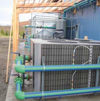

100 References References Barleans Organic Oils, USA 100

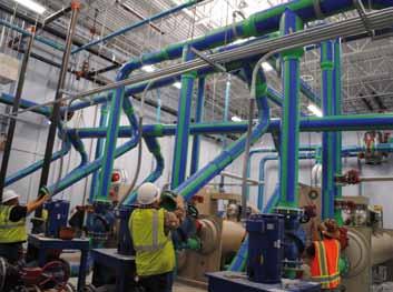

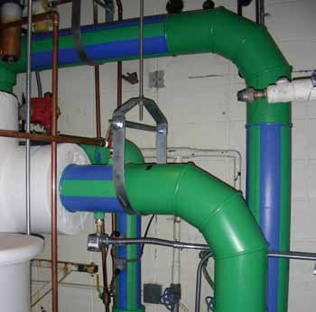

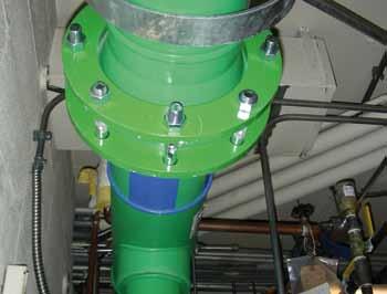
101 References KOYO Bearing, USA Colorado State University, USA 101
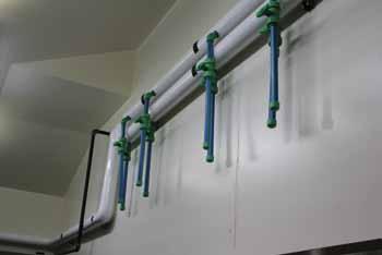
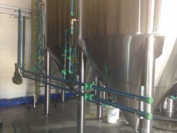

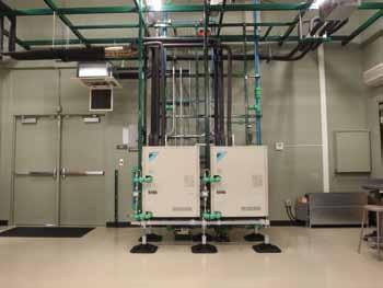

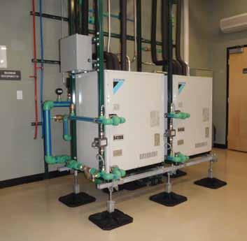
102 References Daikin AC, USA Epic Brewery, USA 102
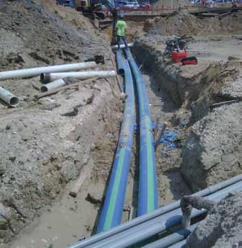
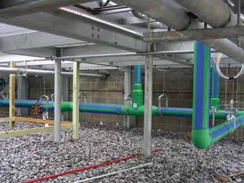

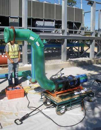
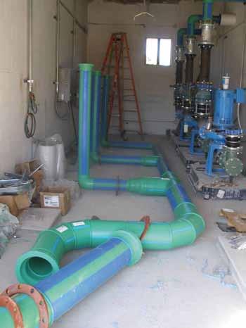
103 References Hancock Medical, USA 103
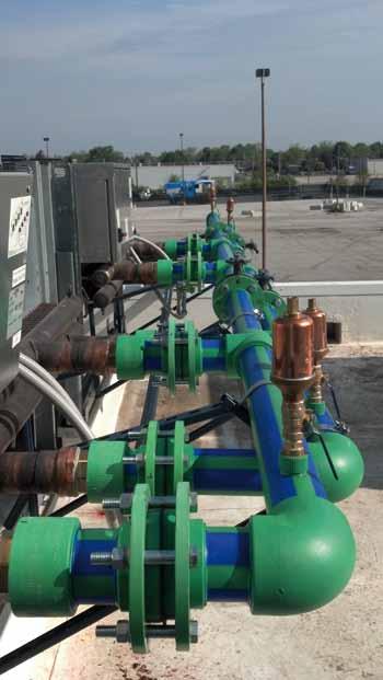
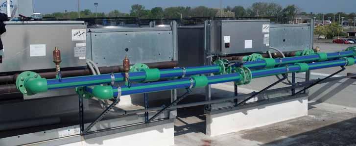
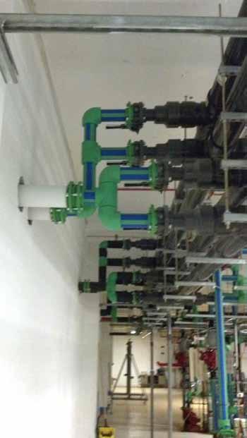
104 References Lifeline Data, USA 104


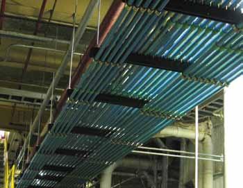

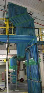
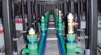
105 References LLNL, USA Neenah Paper, USA 105


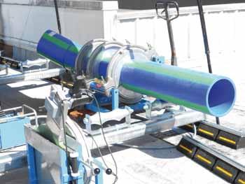
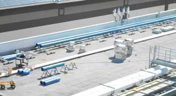

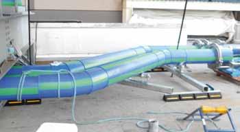
106 References Park Orchard Elementary School, USA IP Casino, USA 106


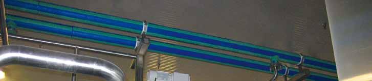
107 References Starbucks, USA 107
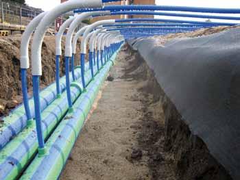
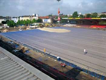


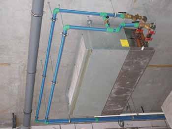
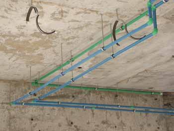
108 References Flex Tower, RAK, UAE Millerntor stadium, FC St. Pauli 1910 e.v. 108


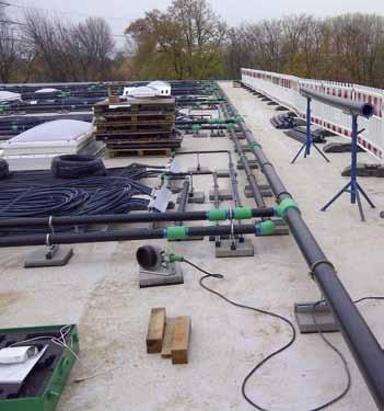
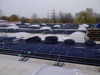
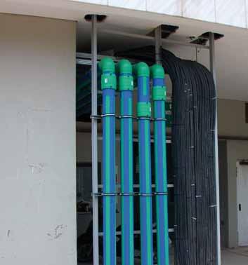
109 References Hellenic Telecoms AG, Athens, Greece Ecolab, Monheim 109

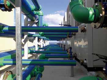


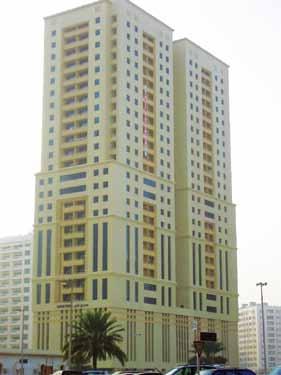
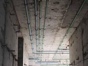
110 References Hotel Kalimera, Kreta, Greece Al Sayegh Tower, Sharjah, UAE 110
111 Transport and Storage TRANSPORT AND STORAGE aquatherm PP-R - pipes may be stored outside at any temperature. A solid base for the pipe is very important to avoid a deformation of the pipes while in transport and storage. At temperatures below 0 C it is possible to damage the pipes through strong impacts. The material has to be treated with caution at low temperatures. 30 mm 30 mm 6 16 x 2,7 SDR mm6 16 x 2,7SDR mm6 16 x 2,7 SDR mm6 16 x 2,7SDR mm6 In spite of its high resistance aquatherm - pipes should be treated with care. Madeunit: Madeunit: Madeunit: Madeuni nit: m packing Art.-No in Germany 100 m packing Art.-No in Germany 100 m packing Art.-No in Germany 100 m packing in 30 mm mmmm 330 mm mm mm 90 mm 30 mm 90 mm 30 mm mm mm 2623 UV-radiation has effects on all high polymer plastics. Do not store permanently outdoor. Maximum storage time (outdoor) is 6 months mm m
112 Product list Table of contents aquatherm blue pipe-pipes Fastening material Fittings Weld-in saddle Threaded connections and accessories Transition pieces Screwed connections and counter parts Distributors Valves and accessories Cutting tools, welding devices Welding machines and welding jig Butt welding machines & electrofusion device Peeling tools Saddle welding tools Drills & saddle peeling tool 112
113 climatherm our specialty for distrib uting cooling and heating in closed systems as well as in several industrial applications, will become aquatherm blue. This system was developed 10 years ago in order to prevent corrosion in air conditioning pipes and quickly expanded its range of application, with many pos itive features for other fields of piping installation. It has gone on to find success around the world in hotels, stadiums, schools, offices, and industrial applications. aquatherm blue Pipe system made of polypropylene for chilled, hot fluid and various industrial applications article-no. old brand name new brand name company system Standard Dimension Ratio structure of pipe special feature of pipe climatherm SDR11 aquatherm blue SDR 11 S PP-R climatherm faser composite pipe SDR7.4/SDR11/SDR 17.6 aquatherm blue climatherm faser composite pipe SDR7.4/SDR11/SDR17.6 UV aquatherm blue SDR 7.4/SDR 11/ SDR 17.6 SDR 7.4/SDR 11/ SDR 17.6 MF material PP-R MF UV PP-R climatherm faser composite pipe SDR7.4/SDR11 OT aquatherm blue SDR 7.4/SDR 11 MF OT PP-R climatherm faser composite pipe SDR7.4/SDR11 ISO aquatherm blue SDR 11/SDR 17.6 MF TI PP-R climatherm faser composite pipe SDR7.4/SDR11 OT ISO aquatherm blue SDR SDR 11 MF OT-TI PP-R 113
114 aquatherm blue pipe SDR 7.4 / 11 / 17.6 MF Structure of pipe: Material: MF = multilayer, with fibre reinforced fusiolen PP-R Pipe series: SDR 7.4 / S 3.2 & SDR11 / S 5 & SDR 17.6 / S 8.3 Standards: Colour: Form supplied: Packing Unit: SKZ HR 3.28, ASTM F 2389, CSA B , ISO blue with 4 wider green stripes ø mm straight lengths 4 m ø mm straight lengths 5.8 m PU in meter s di d Application: +C Mechanically stabilized through a fibre mix integrated in the middle layer of the fusiolen PP-R. SDR Art.-No. Dimension d [mm] Wall thickness s [mm] Internal diameter di [mm] Water content [l/m] Weight [kg] DN PU [m] Socket welding ,8 14,4 0,163 0, ,5 18,0 0,254 0, ,4 23,2 0,423 0, ,9 26,2 0,539 0, ,7 32,6 0,834 0, ,6 40,8 1,307 0, ,8 51,4 2,074 1, ,8 61,4 2,959 1, ,2 73,6 4,252 2, ,0 90,0 6,359 3, ,4 102,2 8,199 4, Butt welding ,6 130,8 13,430 6, , ,2 163,6 21,010 10, , ,7 204,6 32,861 16, , ,6 257,8 52,172 25, , ,2 290,6 66,29 32, , ,3 327,6 84,290 41, , ,9 368,2 106,477 52, ,8 Socket welding ,1 110,8 9,637 2, Butt welding ,1 141,8 15,792 4, , ,4 177,2 24,661 7, , ,2 221,6 38,568 10, , ,9 279,2 61,223 17, , ,1 314,8 77,832 21, , ,7 354,6 98,756 27, , ,5 399,0 125,036 34, , ,4 443,2 154,272 43, , ,7 496,6 193,688 53, , ,7 558,6 245,070 67, ,8 114
115 aquatherm blue pipe SDR 7.4 / 11 / 17.6 MF UV Structure of pipe: Special feature of pipe: MF = multilayer, with fibre reinforced UV resistant Material: fusiolen PP-R Pipe series: SDR 7.4 / S 3.2 & SDR11/SDR 17.6 / S 8.3 Standards: SKZ HR 3.28, ASTM F 2389, CSA B , ISO di d Colour: Form supplied: Packing Unit: Application: outside: black, inside: blue ø mm straight lengths 4 m ø mm straight lengths 5.8 m PU in meter s +C UV-resistant. Mechanically stabilized by a fibre mixture, integrated in the middle layer of fusiolen PP-R. SDR Art.-No. Dimension d [mm] Wall thickness s [mm] Internal diameter di [mm] Water content [l/m] Weight [kg] DN PU [m] Socket welding ,8 14,4 0,163 0, ,5 18,0 0,254 0, ,4 23,2 0,423 0, ,9 26,2 0,539 0, ,7 32,6 0,834 0, ,6 40,8 1,307 0, ,8 51,4 2,074 1, ,8 61,4 2,959 1, ,2 73,6 4,252 2, ,0 90,0 6,359 3, ,4 102,2 8,199 4, Butt welding ,6 130,8 13,430 7, , ,2 163,6 21,010 10, , ,7 204,6 32,861 16, , ,6 257,8 52,172 26, , ,2 290,6 66,292 33, , , ,145 41, , ,9 368,2 106,423 52, , ,1 141,8 15,784 4, , ,4 177,2 24,649 7, , ,2 221,6 38,549 11, , ,9 279,2 61,193 17, , ,1 314,8 77,793 21, , ,7 354,6 98,707 27, , , ,973 34, , ,4 443,2 154,195 42, , ,7 496,6 193,590 52, , ,7 558,6 244,947 66, ,8 115
 Structure of pipe: Special feature of pipe: MF = multilayer, with fibre reinforced OT = oxygen tight Oxygen-Bar PP-R PP-R-GF PP-R Material: fusiolen PP-R Pipe series: SDR 7.")
116 aquatherm blue pipe SDR 7.4 / 11 MF OT B (2:1) Structure of pipe: Special feature of pipe: MF = multilayer, with fibre reinforced OT = oxygen tight Oxygen-Bar PP-R PP-R-GF PP-R Material: fusiolen PP-R Pipe series: SDR 7.4 / S 3.2 & SDR11 / S 5 Standards: DIN 8077 / 78, DIN EN ISO 15874, ASTM F 2389, CSA B , ISO Colour: Form supplied: Packing Unit: Application: blue ø mm straight lengths 4 m ø mm straight lengths 5,8 m PU in meter S B di d +C Oxygen tight by diffusion barrier. Mechanically stabilized through a fibre mix integrated in the middle layer of fusiolen PP-R. SDR Art.-No. Dimension d [mm] Wall thickness s [mm] Internal diameter di [mm] Water content [l/m] Socket welding Weight [kg] ,8 14,4 0,163 0, ,5 18,0 0,254 0, ,4 23,2 0,423 0, ,7 32,6 0,834 0, ,6 40,8 1,307 0, ,8 51,4 2,074 1, ,8 61,4 2,959 1, ,2 73,6 4,252 2, ,0 6,359 3, ,4 102,2 8,199 4, Butt welding ,6 130,8 13,430 6, , ,2 163,6 21,010 10, , ,7 204,6 32,861 16, ,8 DN PU [m] aquatherm blue pipe - SDR 11 S Structure of pipe: S (single) Material: fusiolen PP-R Pipe series: SDR 11/ S 5 Standards: DIN 8077 / 78, DIN EN ISO 15874, ASTM F 2389, CSA B , NSF 14, ISO Colour: blue Form supplied: 4 m straight lengths, also* in coils Packing Unit: PU in meter Application: s di d +C SDR 11 Art.-No. Dimension d [mm] Wall thickness s [mm] Internal diameter di [mm] Water content [l/m] Weight [kg] ,9 16,2 0,206 0, ,3 20,4 0,327 0, ,9 26,2 0,539 0, * 20 1,9 16,2 0,206 0, * 25 2,3 20,4 0,327 0, * 32 2,9 26,2 0,539 0, DN PU [m] 116
climatherm We set the standards for quality and reliability! P I P E S Y S T E M S
 climatherm We set the standards for quality and reliability! P MADE IN I P E S Y S T E M S GERMANY aquatherm-climatherm The climatherm-pipe system includes all elements for the pipe system installation
The future of pipe is Green Welcome!
 The future of pipe is Green Welcome! Contents 1. Aquatherm A New Generation of Pipe 2. Pipe Generations 3. Demonstration 4. Fields of Application 5. Advantages and Characteristics 6. Questions? 2 Aquatherm
FLEXIBLE PREINSULATED PIPES
 FLEXIBLE PREINSULATED PIPES Our production site Based in Casalromano, near Mantua, about 100 km from Milan, our plant covering an area of 50,000 square metres [5,000 of which are roofed], we manufacture
aquatherm PP-R Handling, Transport & Storage Instructions.
 aquatherm PP-R Handling, Transport & Storage Instructions. HANDLING AND WELDING AT LOWER TEMPERATURES. At temperatures below +5 C aquatherm PP-R pipes or fittings can be damaged by high impacts, such as
COOLSAFE PRE-INSULATED PIPING SYSTEMS
 PRE-INSULATED PIPING SYSTEMS EN The Plastics Experts. As an effective solution for thermally insulated piping, AGRU offers the pre-insulated piping system. This system out of PE 100 is specially designed
Edition: aquatherm red. Pipe system made of polypropylene for fire sprinkler systems. aquatherm state of the pipe
 Edition: 05.2014 aquatherm red Pipe system made of polypropylene for fire sprinkler systems aquatherm state of the pipe Our sales and delivery conditions (January 2014) and the contacts of our technical
colours of innovation aquatherm state of the pipe
 colours of innovation aquatherm state of the pipe 1 aquatherm & PARTNER WORLDWIDE Canada USA EL Salvador Chile Portugal Spain France Great Britain Iceland Faeroe Islands Belgium Netherlands Slovenia Denmark
Edition: aquatherm blue. Pre-insulated pipe systems made of polypropylene for district heating. aquatherm green. aquatherm state of the pipe
 Edition: 2.2017 aquatherm green aquatherm blue Pre-insulated systems made of polypropylene for district heating ti ti aquatherm state of the Our sales and delivery conditions (January 2014) and the contacts
Ø mm. SYSTEM KAN-therm. High quality for reasonable price TECHNOLOGY OF SUCCESS ISO 9001
 Ø 16 110 mm SYSTEM KAN-therm PP High quality for reasonable price TECHNOLOGY OF SUCCESS Contents 3 System KAN-therm PP The material... 94 Sanitary systems installation... 95 Pipes... 95 Thermal elongation...
Polyethylene for biogas plants
 Polyethylene for biogas plants From Ulrich Seidelt 1 1. Abstract Only a verified quality of materials and components can ensure a long time life cycle and a failure-free operation of biogas plants. To
Edition: aquatherm green aquatherm blue. Pre-insulated pipe systems made of polypropylene for district heating. aquatherm state of the pipe
 Edition: 05.2014 aquatherm green Pre-insulated systems made of polypropylene for district heating ti ti aquatherm state of the Our sales and delivery conditions (January 2014) and the contacts of our technical
aquatherm red Pipe system made of polypropylene for fire sprinkler systems aquatherm state of the pipe
 aquatherm red Pipe system made of polypropylene for fire sprinkler systems aquatherm state of the pipe Our sales and delivery conditions (January 2012) and the contacts of our technical sales and distribution
Submittal for Aquatherm Piping System
 Submittal for Aquatherm Piping System Project Name: Project Location: Date: To whom it may concern, We are proposing to upgrade the piping parts on the above project to the polypropylene Aquatherm Green
aquatherm state of the pipe
 Edition: 07.2017 We are aquatherm INDEPENDENT, DETERMINED, RELIABLE, LEADING aquatherm state of the pipe 1 USA Canada EL Salvador Chile Spain Portugal France Iceland Great Britain Faeroe Islands Norway
Submission Report for The New National Stadium - Wembley
 George Fischer Piping Systems GF System Selection AQUASYSTEM Technical Submission Report for The New National Stadium - Wembley GF Piping Systems Introduction 1. INTRODUCTION George Fischer is a leading
Insultherm TECHNICAL SUBMISSION DYNATHERM PP-RCT
 Insultherm TM P R E - I N S U L AT E D P I P E S Y S T E M S TECHNICAL SUBMISSION DYNATHERM PP-RCT Applications & Benefits In a large number of projects, major benefits can be achieved by using the Insultherm
Large plastic pipe technology. Large diameter pressure pipe. up to DN/ID 5000 mm
 Large plastic pipe technology Large diameter pressure pipe up to DN/ID 5000 mm Powerful and designed according to YOUR specifications Large diameter pressure pipes No sagging and less wallthickness saves
SSAB water mains. A reliable and economically advantageous solution for water supply.
 SSAB water mains A reliable and economically advantageous solution for water supply www.ssab.com/infra SSAB S SYSTEM OF WATER MAINS DISTRIBUTES CLEAN WATER SAFELY A system made up of steel water mains
DESO PPR Pipe System
 DESO PPR Pipe System Nowadays, polypropylene is one of the most extensively used plastics in the world due to its diverse applications and being economical. DESO PP-R (Type 3) Pipes and Fittings are made
PP-R PRE-INSULATED PIPE SYSTEMS. for district heating and cooling
 PP-R PRE-INSULATED PIPE SYSTEMS for district heating and cooling CONTENTS System Features 4. Medium pipes 4. Insulation 6.3 Loss of heat and cooling energy 6.4 Casing pipes 7.5 Blue PP-R pipe data sheet
EPIC B2134 J345 X721 1/2015
 EPIC B2134 J345 X721 1/15 Ekoplastik System made from granulate of leading European producers unique 3 layer pipe reinforced with basalt fiber new materials of 4. generation PP-RCT high pressure and temperature
A. ASTM F Standard Specification for Pressure-rated Polypropylene (PP) Piping Systems.
 Piping Systems.") SECTION 221114 - PART 1 - GENERAL 1.1 SUMMARY A. This Section includes the water distribution piping system, including potable cold, hot and hot water piping including associated fittings, and specialities
SECTION 221114 - PART 1 - GENERAL 1.1 SUMMARY A. This Section includes the water distribution piping system, including potable cold, hot and hot water piping including associated fittings, and specialities
Technical Instruction aquatherm red pipe
 1.1 Scope 2 1.2. Definitions 2 1.2.1 aquatherm red pipe SDR7,4 MF HI 2 1.2.2 aquatherm red pipe fittings 2 1.3 General 2 1.4 Use of aquatherm red pipe in sprinklered installations 2 1.4.1 Occupancy 2 1.4.2
Presented by: Thermoplastic Piping
 Presented by: Thermoplastic Piping VARI-TECH is an acronym for VARIOUS TECHNOLOGIES. The original thrust of the company was to bring engineered products and services to the Northeastern United States market.
Underground System. Description
 Description Insapipe is a factory fabricated and insulated Underground piping system designed for direct burial into an unlined trench. The product is manufactured generally to British Standard 4508 for
Sanitary Installations. Product Catalogue.
 Sanitary Installations Product Catalogue www.hydroplast.de Pipe SDR 11 Art. no D s kg/m m/pack G11001 20 1,9 0,107 200 G11002 25 2,3 0,164 160 G11003 32 2,9 0,267 80 G11004 40 3,7 0,412 60 G11005 50 4,6
Installation Guide BLUE904 PEX MUNICIPAL WATER SERVICE TUBING. We Build Tough Products for Tough Environments
 Installation Guide BLUE904 PEX MUNICIPAL WATER SERVICE TUBING W A T E R S E R V I C E T U B I N G We Build Tough Products for Tough Environments Blue904 Installation Guide 1 TABLE OF CONTENTS Introduction...................................2
KELIT PEX 95R-10 KELIT PEX 115R-16 %URFKXUH
 KELIT PEX 9R-0 KELIT PEX R- %URFKXUH 0 KELIT PEX 9R-0, KELIT PEX R- Brochure 0 KELIT PEX 9R-0 KELIT PEX R- Brochure Table of Contents System description. Pipe products Flexible pipe KELIT PEX 9R-0 Flexible
SurePEX MAXIMUM SAFETY HIGHEST FLEXIBILITY
 en SurePEX MAXIMUM SAFETY HIGHEST FLEXIBILITY Worldwide Competence in Plastics As an innovative company AGRU is always interested in establishing new products in the market that put the customers benefits
aquatherm red Pipe system made of polypropylene for fire sprinkler systems aquatherm state of the pipe
 aquatherm red Pipe system made of polypropylene for fire sprinkler systems aquatherm state of the pipe Our sales and delivery conditions (January 2012) and the contacts of our technical sales and distribution
Application technology, 5th edition. Volume III: Fonterra radiant heating and cooling
 Application technology, 5th edition Volume III: Fonterra radiant heating and cooling Fonterra Active General Fonterra Active General Fonterra Active was developed specifically for thermal activation of
FlexPipe. Pre-Insulated Flexible Pipe Systems for District Heating & Cooling
 FlexPipe Pre-Insulated Flexible Pipe Systems for District Heating & Cooling Ecopex Range For civil and industrial district heating networks Ecopex pre-insulated pipe systems consists of a cross linked
SIROPLAST-K. Pipe system for civil engineering subsoil drainage inspection chambers and subsoil drainage pipes to DIN
 HEGLER II/1 Pipe system for civil engineering subsoil drainage inspection chambers and subsoil drainage pipes to DIN 4262-1 : Pipe system consisting of inspection chambers and subsoil drainage pipes. Twin
Wherever Your Imagination Takes You NO.1 WORLDWIDE IN RIGID PVC FOAM SHEETS
 Wherever Your Imagination Takes You NO.1 WORLDWIDE IN RIGID PVC FOAM SHEETS Working with Kömacel Machining Kömacel sheets can be easily and quickly worked with standard tools to process wood and metal
PREINSULATED PIPE SYSTEMS FOR HOT WATER NETWORKS
 Saules iela 8, Ozolnieki, Ozolnieku pagasts, Ozolnieku novads, LV 3018 Tālr.: +371 6 30 50600, fakss: +371 6 30 50230 PREINSULATED PIPE SYSTEMS FOR HOT WATER NETWORKS Catalogue AI 9.05 2014 CONTENT Introduction
Construction. Tricosal Waterstops - Tricomer. Waterstops for joint sealing in watertight concrete construction according to DIN and DIN
 Construction Product Data Sheet Edition 19 April 2013 Tricosal Waterstops - Tricomer Waterstops for joint sealing in watertight concrete construction according to DIN 18541 and DIN 18541-2 Product Description
B U I L D I N G T E C H N O L O G Y. f ri p e x- s a n quick, flexible, reliable and simple
 B U I L D I N G T E C H N O L O G Y f ri p e x- s a n quick, flexible, reliable and simple The plastic pipe: Exceptional water quality Highly resistant to ageing The problems which may occur when metal
THERMOPLASTIC MANHOLES FOR AND OUT OF LARGE DIAMETER PIPES
 THERMOPLASTIC MANHOLES FOR AND OUT OF LARGE DIAMETER PIPES Introduction: Manholes are, beside pipes and fittings, an essential element of underground pipe-systems. They are used for maintenance and the
Specification texts FRIAFIT sewage system
 Specification texts FRIAFIT sewage system Norm Conformity The FRIAFIT sewage system of PE 100 complies with EN 12666 and hence is deemed a regulated construction product. It therefore does not need general
TECHNO GROUP TECHNO PLAST. TECHNO PLAST : Pipe Extrusion manufacturer. TECHNO FIT : Injection moulding manufacturer
 TECHNO GROUP TECHNO PLAST : Pipe Extrusion manufacturer TECHNO FIT : Injection moulding manufacturer TECHNO ALIMCO : Blow Moulding manufacturer TECHNO COR : Corrugated Pipe manufacturer TECHNO THERM :
Contents. 3. Overview Pipe. 8. Fittings. 9. Features & benefits Installation considerations. 16. Jointing instructions
 TECHNICAL MANUAL Contents 3. Overview 4-7. Pipe 8. Fittings 9. Features & benefits 10-15. Installation considerations 16. Jointing instructions 17-22. Ezi Pex Push fitting 23. Warranty www.ezipex.com.au
A. This section is intended to provide design guidelines for Utility Direct Buried Piping and Conduit Systems.
 Date Description of Change Pages / Sections Modified ID 6/15/16 Entire document - mgl44 PART 1 - INTRODUCTION 1.1 PURPOSE A. This section is intended to provide design guidelines for Utility Direct Buried
Hot & Cold Water Piping Systems made of Polypropylene TECHNICAL MANUAL POLO-ECOSAN MADE IN GERMANY
 Hot & Cold Water Piping Systems made of Polypropylene TECHNICAL MANUAL POLO-ECOSAN MADE IN GERMANY TABLE OF CONTENTS System Description 1.1 POLO-ECOSAN Installation System... 6 1.1.1 System Components...
Regupol CONSTRUCTION. Regupol BA. Heavy duty screed isolation. Regupol BA. Excellent impact performance.
 CONSTRUCTION Regupol Heavy duty screed isolation Excellent impact performance www.berleburger.de CONSTRUCTION The properties heavy duty screed isolation Offers long term performance, with minimal creep,
KÖMACEL THE INTEGRAL FOAM SHEET FOR UNIVERSAL APPLICATION!
 painting. laminating. cladding. KömaCel - integral foam sheet with the very best values - both inner and outer Processing information for: window manufacturers. plumbers. manufacturers of roller shutters.
PRODUCT CATALOGUE PROFLEXR. Thermal Insulation. CFC free HCFC free Zero Ozone Depletion Potential (ODP) Taking care of energy and Environment
 Taking care of energy and Environment") PRODUCT CATALOGUE PROFLEXR Thermal Insulation CFC free HCFC free Zero Ozone Depletion Potential (ODP) Taking care of energy and Environment PROFLEX Proflex polyolefin foam thermal insulation for AirConditioning,
PRODUCT CATALOGUE PROFLEXR Thermal Insulation CFC free HCFC free Zero Ozone Depletion Potential (ODP) Taking care of energy and Environment PROFLEX Proflex polyolefin foam thermal insulation for AirConditioning,
Single-vendor system solutions Systems for producing temperature-resistant pipes
 Single-vendor system solutions Systems for producing temperature-resistant pipes Engineering Value Impressive machine combination Single-screw extruders for manufacturing multi-layered pipes 3 Extruder
Large Diameter Piping System DURABLE PE-PIPING SYSTEM FOR HIGH- VOLUME FLOW
 Large Diameter Piping System DURABLE PE-PIPING SYSTEM FOR HIGH- VOLUME FLOW 1 The Plastics Experts. AGRU Pipe & Fitting Systems offer a complete range of high-quality pipes, fittings, valves and customized
SECTION COMMON WORK RESULTS FOR FIRE SUPPRESSION
 Page 210500-1 SECTION 210500 - PART 1 - GENERAL 1.1 RELATED DOCUMENTS A. Drawings and general provisions of the Contract, including General and Supplementary Conditions and Division 01 Specification Sections,
HDPE HDPE. Factory PRESSURE PIPING SYSTEM DRAINAGE & SEWERAGE PIPING CABLE DUCT & SUB DUCT. Since 2002 HDPE. for Sewerage Storm Water System HDPE
 PRESSURE PIPING SYSTEM DRAINAGE & SEWERAGE PIPING CABLE DUCT & SUB DUCT for Sea Water Intake for Gas Transportation for Sewerage Storm Water System Manholes Factory Since 2002 for Cold Water Supply & Irrigation
CALPEX Low Temperature System
 CALPEX Low Temperature System Flexibly towards a safe future Nou! Ø 125/182 Ø 160/250 NEW: CALPEX PLUS 22% improved insulation Contents Utilise your advantages 3 4 System description 5 6 Pressure loss
PREMANT. Pre-insulated steel pipe system
 Pre-insulated steel pipe system Heat insulated - reliable - monitoring possible Brugg Rohrsysteme provides integrated solutions from heat uncoupling all the way to the end consumer. Our complete range
HDPE HDPE. Factory PRESSURE PIPING SYSTEM DRAINAGE & SEWERAGE PIPING CABLE DUCT & SUB DUCT. Since 2002 HDPE. for Sewerage Storm Water System HDPE
 PRESSURE PIPING SYSTEM DRAINAGE & SEWERAGE PIPING CABLE DUCT & SUB DUCT for Sea Water Intake for Gas Transportation for Sewerage Storm Water System Manholes Factory Since 2002 for Cold Water Supply & Irrigation
h Installation Manual
 h Installation Manual 1 General Information The installation of HOBAS GRP Pipes is subject to applicable standards and guidelines such as EN 1610 and ISO/ TS 10465-1. Correct installation always requires
CEMPUR THE PERFECT COMBINATION OF INNOVATIVE COATING EXPERTISE
 CEMPUR THE PERFECT COMBINATION OF INNOVATIVE COATING EXPERTISE Ductile cast-iron pipes with optimised energy efficiency for high-performance applications CEMPUR Our strongest component CEMPUR pipes feature
PETREX -CNT. Pipe systems for petrol stations Technical details
 PETREX - Pipe systems for petrol stations Technical details Contents 1.0 1.0 Contents 1.10 1.100 System description System description PETREX - 1.11 1.11.01 Product overview Piping, connections, fittings
Edition: aquatherm red. Pipe system made of polypropylene for fire sprinkler systems. aquatherm state of the pipe
 Edition: 01.2015 aquatherm red Pipe system made of polypropylene for fire sprinkler systems aquatherm state of the pipe Our sales and delivery conditions (January 2014) and the contacts of our technical
ELASTICALLY SEPARATED FLOOR
 MATERIALS FOR TECHNICAL INNOVATIONS ELASTICALLY SEPARATED FLOOR WERKSTOFFE Noise in buildings is extremely irritating. Disruptions can have a wide variety of causes. For instance, the residents produce
Selection of materials
 Polypropylene (PP) is a partially-crystalline thermoplastic from the polyolefin group of materials, and it is characterized by its low density when compared to other thermoplastics. A unique combination
Concrete Protection CONCRETE PROTECTIVE LINERS
 Concrete Protection CONCRETE PROTECTIVE LINERS EN Precast pipe with AGRU Sure Grip Sure Grip system The Sure Grip concrete protective liner system, developed and patented by AGRU, is a high-quality solution
Cold Rooms Kide
 COLD ROOMS Cold Rooms 2 Cold under control KIDE it is a business Group manufacturer of cold-rooms, insulation panels, insulated doors, refrigeration units and drying units, offering integral solutions
Enjoy some peace and silence and the satisfaction of your customers by using MÜPRO s special vibration control products
 Vibration control Enjoy some peace and silence and the satisfaction of your customers by using MÜPRO s special vibration control products Even today, the most expensive defects in buildings are still those
Phenolic Foam (PF) Insulation
 Insulation") Class O CFC & HCFC Free Phenolic Foam (PF) Insulation The Superior Insulation Foam The Quality Insulation Products for Many Diverse Application Chilled Water Pipe and Duct Insulation Slab Insulation Roof
Class O CFC & HCFC Free Phenolic Foam (PF) Insulation The Superior Insulation Foam The Quality Insulation Products for Many Diverse Application Chilled Water Pipe and Duct Insulation Slab Insulation Roof
PIPE SYSTEM MADE OF POLYETHYLENE RT TYPE 2 INNOVATIVE PIPE SYSTEMS
 PIPE SYSTEM MADE OF POLYETHYLENE RT TYPE 2 INNOVATIVE PIPE SYSTEMS 1 Company Profile aquatherm introduced PPR pipe systems to New Zealand in 1999 with our principal product line fusiotherm pipe system
PP-R pipes and fittings
 PP-R pipes and fittings Enviromental protection Quality raw material Prevent mildew Warrenty series CLASSIC CLASSICUV POWER POWERPLUS POWERUV FIBERREINFORCED 4 5 Mission Market adaptability Plastofer is
Panel elements. Closed Panels Transparent Panels Non-Transparent Panels Mesh Panels Accessories for Panel Elements
 Panel elements Closed Panels Transparent Panels Non-Transparent Panels Mesh Panels Accessories for Panel Elements Panel elements Products in this section Acrylic Glass Polycarbonate PET-G Sheet Material
Pipes APPLICATIONS PIPES AND FITTINGS COMPATIBILITY. A full range for the perfect installation. Comap provides a wide choice to complete
 APPLICATIONS Comap connection systems combine different fitting technologies with pipes of different materials to cover the maximum number of applications. PIPES AND FITTINGS COMPATIBILITY Fitting range
HDPE PIPE SYSTEM ACE FLOWTECH CO., LTD. GLOBAL PIPING SOLUTIONS PROVIDER!
 R ACE FLOWTECH CO., LTD HDPE PIPE SYSTEM R Ace Flowtech Co., Ltd, a subsidiary of JM Quan en Group Office address: No.2, 2-1601, Rongyuan Road, Huayuan Industrial Park, Tianjin Binhai Hi- Tech Area, Tianjin
Roofing. Polymeric sheet for roof waterproofing. Product Description. Tests. Product Data Sheet Edition _1
 Product Data Sheet Edition 2014-09_1 Polymeric sheet for roof waterproofing Product Description (thickness 1.5 mm) is a Polyester reinforced, multi-layer, synthetic roof waterproofing sheet based on premium-quality
1. General information
 Contents 1. General information... 2 2. Features Applications... 3 3. Features Advantages... 4 4. General Precautions... 5 5. Features Material Properties and Characteristics... 6 6. Features Fiber Reinforced
TECElogo. The installation system for professionals
 TECElogo The installation system for professionals 2 TECElogo combines highest safety with maximum comfort. That wins over our customers and their customers. TECElogo the company Dear customer, Since its
PP-R & PEX Systems. Pioneered ADVANCED GERMAN TECHNOLOGY
 Pioneered PP-R & PEX Systems ADVANCED GERMAN TECHNOLOGY PO Box 30739, Al Jazira, Al Hamra, Ras Al Khaimah, United Arab Emirates Tel: +971 7 2447128 I Fax: +971 7 2447129 I Toll Free 800-RAKTHERM ( 72584376
Sure-Grip System. A System with Benefits. Concrete Protection
 Concrete Protection Concrete Protection The Sure-Grip concrete protective liner system, developed and patented by Agru, is a high-quality innovative solution for the long-term protection of concrete structures.
PVC pressure pipe (grey)
") PVC pressure pipe (grey) PVC pressure pipe is used for the transport of liquids under pressure. The product range is divided into various pressure classes that indicate the maximum working pressure. The
PVC pressure pipe (grey) PVC pressure pipe is used for the transport of liquids under pressure. The product range is divided into various pressure classes that indicate the maximum working pressure. The
Pexfit Pro. Instructions for Use. Year built: from 01/2009 en_int
 Pexfit Pro Instructions for Use Year built: from 01/2009 en_int Pexfit Pro 2 from 23 Table of contents Table of contents 1 About these instructions for use 4 1.1 Target groups 4 1.2 Labelling of notes
LET FLY YOUR IDEAS EX-CEL PLASTICS LIMITED IS A SUSIDIARY OF
 LET FLY YOUR IDEAS EX-CEL PLASTICS LIMITED IS A SUSIDIARY OF EX-CEL IMPRESS is the perfect choice product for High Quality Digital Printing Application. Available in a wide range of sheets sizes and thicknesses.
Exterior Wall Solutions Building Shell
 A strong, water tight and thermally insulated building shell will ensure the buildings sustainability of usage over time. The Exterior Shell is the most important factor of protection to ensure that the
TECHNICAL DATA SHEET
 1. DESCRIPTION QuickSpray Industrial is an instant curing, spray applied, seamless, and flexible protective membrane. QuickSpray Industrial sits in the middle of VIP`s high performance coatings range and
The DUOPEX WATER. Advantages of the Duopex Water
 duopex water manual The DUOPEX WATER Pipe and Fitting System is designed for 16mm-63mm potable hot and cold water applications. This revolutionary alternative for the professional plumber, makes any job
Sika KAB combination joint waterbars waterstopping systems
 PRODUCT DATA SHEET Sika KAB combination joint waterbars Waterbars for waterproofing construction and crack induced shrinkage joints in new reinforced concrete structures PRODUCT- DESCRIPTION KAB 125/KAB
Bridge Drainage Systems
 Bridge Drainage Systems 2 Bridge drains made of cast iron, durable and reliable in use 3 One of the most important preconditions for the perfect functioning of bridge structures is the fast drainage of
.1 Thermal insulation for insulated piping and piping accessories affected by construction and new pipe sections as indicated on drawings.
 BID OPPORTUNITY NO. 253-2011 PAGE 1 OF 8 PART 1 GENERAL 1.1 SUMMARY.1 Section Includes: 1.2 REFERENCES.1 Thermal insulation for insulated piping and piping accessories affected by construction and new
Construction. Sarnafil TS Polymeric membrane for roof waterproofing. Product Description
 January, 2009 Sarnafil TS 77-15 Polymeric membrane for roof waterproofing Construction Product Description Uses Characteristics / Advantages Approval / Standards Sarnafil TS 77-15 (thickness 1.5 mm) is
HT-406 Specification Guide
 2.101 Part 1 - General Pre-insulated HDPE-Jacketed Steel Piping Systems suitable for Steam, Condensate Return, and High Temperature Heating Water. 1.1 Pre-insulated Piping - Furnish a complete HDPE jacketed
Large polyethylene pipes
 Large polyethylene pipes Krah pipes for pressure application Krah-Pipes are large polyolefin pipes up to an internal diameter of 4000mm and a maximum solid wall thickness of 200mm. The preferred jointing
SPC recently concluded a partnership with a leading Italian company providing innovative and complete polyethylene pipe systems in 30 countries.
 50 corrugated pipes SPC celebrates 50 years of manufacturing concrete pipes and related products for the Southern African market. To further serve the region, SPC is proud to announce the manufacturing
Production Technology
 Introduction There has been a need to introduce new QUALITY PRODUCTS in the construction & Cold Storage industry in the region for many years. EIP was set up at Dubai Investment Park in the UAE to address
Pre-insulated pipes for industrial applications
 Pre-insulated pipes for industrial applications [ We document the difference ] www.logstor.com The world s leading producer of pre-insulated pipe systems Contents The world s leading producer of pre-insulated
AESTUVER fire-protection mastic For the AESTUVER expansion joint M
 fermacell AESTUVER product data sheet For the AESTUVER expansion joint M Product is an elastic RTV-1 silicone combined with halogen-free fire retardants. Silicone is a versatile elastomer which is mainly
Aquatherm Australia Pty Limited Technical Support Australian Version 1 Edition 03/10
 AUSTRALIA PROOF CONTENTS 0 Features fusiolen PP-R 3 Permissible working pressures 5 Fields of application of the fusiotherm 6 and climatherm-pipe systems Fusion for fusiotherm, climatherm and aquatherm
Engineering Specifications
 VIEGA PUREFLOW SYSTEM PART 1 GENERAL 1.1 SUMMARY 1.1.1 This specification covers Branch & Main, Parallel Water Distribution Systems (ManaBloc), Cross-linked Polyethylene tubing and fittings using PureFlow
FrostGuard 120 V 120 V PREASSEMBLED ELECTRIC HEATING CABLES FOR PIPE FREEZE PROTECTION AND ROOF & GUTTER DE-ICING INSTALLATION INSTRUCTIONS
 FrostGuard 120 V 120 V PREASSEMBLED ELECTRIC HEATING CABLES FOR PIPE FREEZE PROTECTION AND ROOF & GUTTER DE-ICING INSTALLATION INSTRUCTIONS DESCRIPTION FrostGuard 120 V preassembled self-regulating heating
aquatherm red aquatherm state of the pipe Pipe system made of polypropylene for fire sprinkler systems
 Edition: 05.2016 aquatherm red - Pipe system made of polypropylene for fire sprinkler systems aquatherm red Pipe system made of polypropylene for fire sprinkler systems aquatherm state of the pipe Our
SECTION UTILITY POLYETHYLENE CONTAINMENT PIPE SYSTEMS
 SECTION 02670 UTILITY POLYETHYLENE CONTAINMENT PIPE SYSTEMS PART 1 - GENERAL 1.01 WORK INCLUDED A. Trenching and other excavation. B. Ground water control. C. Pipe bedding. D. Installation of containment
Insulated Panel System. QuadCore IND. Superior FIRE Protection. Unrivalled THERMAL Efficiency. ENHANCED Environmental Credentials
 1 Superior FIRE Protection 2 Unrivalled THERMAL Efficiency 3 ENHANCED Environmental Credentials 4 Longest Performance GUARANTEE Insulated Panel System QuadCore IND Technical Information Projet / Usage
Raci spacer type L ST 503I 2/7
 RACI SPACER TYPE L Mar./10 Rev. 1.0 - General revision Editing L.Manoni Approval G.Borta 1/7 D es c ri pti o n Raci s.r.l. - via Adriano, 101 20128 Milano Italy - www.raci.it tel. +3902262351 fax +390226235215
SECTION PRE-ENGINEERED BUILDING INSULATION
 PART 1 GENERAL SECTION 07213 PRE-ENGINEERED BUILDING INSULATION Microsoft Word Instructions: Display hidden notes to specifier by using "Tools"/"Options"/"View"/"Hidden Text". 1.1 SECTION INCLUDES A. Pre-Engineered
HALFEN HLB LOOP BOX Z-HLB-M50 13-E CONCRETE
 HALFEN HLB LOOP BOX Z-HLB-M50 13-E CONCRETE Translation of the General Certificate of Approval Approval Office: German Institute for Construction Engineering (Deutsches Institut für Bautechnik DIBt) Kolonnenstrasse
Canadian Standards Association Thermoplastic pressure piping compendium
 Contents Technical Committee on Plastic Pressure Piping xx Preface xxiii Foreword xxv B137.0-05, Definitions, general requirements, and methods of testing for thermoplastic pressure piping 1 Scope 3 2