Effect Of Sputter Deposited YSZ Thin Films On The Fracture Behavior Of Dental Bioceramics. Erica Cappelletto Nogueira Teixeira
|
|
|
- Abigayle Pearson
- 5 years ago
- Views:
Transcription
1 Effect Of Sputter Deposited YSZ Thin Films On The Fracture Behavior Of Dental Bioceramics Erica Cappelletto Nogueira Teixeira A dissertation submitted to the faculty of the University of North Carolina at Chapel Hill in partial fulfillment of the requirements for the degree of Doctor of Philosophy in the Curriculum in Applied and Materials Sciences. Chapel Hill 2008 Approved by Advisor: Dr. Jeffrey Y. Thompson Reader: Dr. Brian R. Stoner Reader: Dr. Albert Banes Reader: Dr. Nalin Parikh Reader: Dr. Otto Zhou
2 ABSTRACT Erica Cappelletto Nogueira Teixeira: Effect of sputter deposited YSZ thin-films on the fracture behavior of dental bioceramics (Under the direction of Dr. Jeffrey Y. Thompson) The fracture behavior of dental bioceramic materials was evaluated under physiologic conditions when modified by yttria stabilized zirconia (YSZ) thin film deposition. It was hypothesized that changing the YSZ thin film properties will produce a significant enhancement in the strength of bioceramic materials, ultimately promoting a more fatigue resistant construct. Porcelain, alumina, and zirconia were evaluated in terms of dynamic fatigue for an initial characterization of their fracture behavior. Data showed that strength degradation occurred in all three materials, most drastically in porcelain. Initial strength measurements, focused on depositing YSZ thin films on three unique substrates; porcelain, alumina, and zirconia, were carried out. A significant increase in strength was observed for alumina and porcelain. Since strength alone is not enough to characterize the fracture behavior of brittle materials, coated specimens of porcelain and zirconia were subjected to dynamic fatigue and Weibull analysis. Coated YSZ porcelain specimens showed a significant increase in strength at all tested stressing rates. YSZ coated zirconia specimens showed similar strength values at all stressing rates. The effect of film thickness on porcelain was also evaluated. Data demonstrated that film thickness alone does not appear to control increases in the flexural strength of a modified substrate. It is expected that deposition induced stress in YSZ sputtered films does not change with ii
3 film thickness. However, a thicker film will generate a larger force at the film/substrate interface, contributing to delamination of the film. It was clear that in order to have a significant improvement in the fracture behavior of porcelain, changing the thickness of the film is not enough. The columnar structure of the YSZ films developed seems to favor an easy path for crack propagation limiting the benefits expected by the coating. The effect of a multilayered film, composed by brittle/ductile (YSZ/parylene) layers on porcelain was investigated. Strength measurements of porcelain bars coated with a single layer of parylene, YSZ, and YSZ+parylene were different than the uncoated group. The greatest increase in strength was shown when a multilayered structure was applied. SEM analyses show that crack deflection occurs. The effect of a laminate film structure was also evaluated in terms of dynamic fatigue. However, the fatigue behavior decreased for the coated group. It is speculated that the residual stress profile and deposition conditions of this film may have influenced crack propagation. iii
4 TABLE OF CONTENTS LIST OF TABLES... viii LIST OF FIGURES... ix Chapter Page 1. Introduction References Literature Review and Fundamentals Review of ceramic materials used in dentistry Mechanical properties of dental ceramics Surface finish/treatment effects on mechanical properties of brittle substrates Review of sputtering zirconia thin films Review of fatigue behavior of ceramics References Dynamic fatigue of different ceramic materials Introduction Experimental Results Discussion References Yttria stabilized zirconia (YSZ) thin films applied to different substrates...50 v
5 4.1 Introduction Experimental Substrate materials -selection and preparation Sputerring system and deposition parameters Mechanical testing Results Discussion References Dynamic fatigue behavior of ceramic materials modified by surface deposition of a YSZ thin film Introduction Experimental Results Discussion References Effect of YSZ thin film coating thickness on the strength of a ceramic substrate Introduction Experimental Results Discussion References Effect of a multilayer film on the fracture behavior of porcelain Introduction Experimental Part 1-Experimental sequence and results...99 vi
6 Part 2-Experimental sequence and results Discussion Factors involved in the strengthening effect Film stress Flaw modification/flaw tolerance Film structure Effect of the multilayer system in the fatigue behavior Improvements in the multilayer system References Conclusion BIBLIOGRAPHY vii
7 LIST OF TABLES Table 4.1-Flexural strength values for uncoated and coated groups...56 Table 5.1- Mean flexural strength of uncoated and coated porcelain...68 Table 5.2- Fracture strength characteristics of uncoated and coated porcelain according to stressing rates Table 5.3- Mean flexural strength of uncoated and coated zirconia...73 Table 5.4- Fracture strength characteristics of uncoated and coated zirconia according to stressing rates Table Flexural strength (MPa) of porcelain coated with different thin-films Table Material properties used in the stress analysis Table 7.3 -Stress values (MPa) for a multilayer film on a silicon wafer. Negative sign represents compressive values Table 7.4 -Stress values (MPa) for a multilayer film on a porcelain bar. Negative sign represents compressive values viii
8 LIST OF FIGURES Figure 2.1- Crack velocity as a function of strain energy release rate, showing three distinct regions...23 Figure 2.2- Schematic showing the reaction of water molecules into a strained silica network...24 Figure 2.3- Schematic representation of the reaction between water and strained Zr-O-Zr bonds at the crack tip. Reaction steps involved (1) adsorption of water to Zr-O bond, (2) reaction involving proton and electron transfer, (3) formation of surface hydroxyls.(from [46])..25 Figure 3.1- SEM micrograph of fracture surface of a porcelain bar showing initial and critical flaw...37 Figure 3.2- Weibull probability plot and confidence bounds (95%) for the inert strength of porcelain, alumina and YSZ...38 Figure 3.3- Dynamic fatigue data and fatigue parameters of the tested materials...39 Figure 3.4- Lifetime prediction diagram of porcelain based on Weibull probability plot showing strength values at 63.2% and at 5% probability of failure for initial, 1 day, 1 year, and 10 years...40 Figure 3.5- Lifetime prediction diagram of alumina based on Weibull probability plot showing strength values at 63.2% and at 5% probability of failure at initial, 1 day, 1 year, and 10 years 41 Figure 3.6- Lifetime prediction diagram of zirconia based on Weibull probability plot showing strength values at 63.2% and at 5% probability of failure at initial, 1 day, 1 year, and 10 years...42 Figure 3.7- SEM of a polished porcelain surface..43 Figure 3.8- SEM of a polished alumina surface 44 ix
9 Figure 3.9- SEM of a polished zirconia surface 45 Figure 4.1- Schematics of the sputtering process (from Thompson JY, Stoner BR. Thin Film Surface Coatings For Toughened Dental Ceramics, NIH-NIDCR grant 5R01DE Figure 4.2- Representation through pictures of the experimental procedure: A-Porcelain blocks were cut into plates B-Porcelain and zirconia plates were cut into bars C-Porcelain, zirconia, alumina bars were polished D-Grit blaster used to modify one side of the bars E-Deposition chamber and jig (right) used in the sputtering process F-Flexural strength test G-data analysis..55 Figure 4.3-YSZ thin film structure deposited on porcelain substrate 56 Figure 4.4.-Fracture surface of uncoated (sandblasted) porcelain Figure 4.5-Fracture surface of coated porcelain...58 Figure 4.6- Fracture surface of uncoated alumina.58 Figure 4.7-Fracture surface of coated alumina..59 Figure 4.8- Fracture surface of uncoated zirconia.59 Figure 4.9-Fracture surface of coated zirconia...60 Figure 5.1- Environmental chamber used to test specimens in water at 37 0 C...67 Figure 5.2- Dynamic fatigue data and fatigue parameters of the uncoated and coated porcelain..70 Figure 5.3- Scanning electron micrographs of the sandblasted surface (a) and the fracture surface of a porcelain bar (b), and surface (c) and fracture surface of a porcelain bar with YSZ coating (d)..72 Figure 5.4- Dynamic fatigue data and fatigue of the uncoated and coated zirconia...74 Figure 5.5- Scanning electron micrographs of the fracture surface of a sandblasted zirconia bar, and fracture surface of a zirconia bar with YSZ coating..75 x
10 Figure 6.1- Effect of YSZ thin film thickness on the mean flexural strength of modified porcelain bars 84 Figure 6.2- SEM micrograph (2,500X) representative of 1mm thick film on the fracture surface of the porcelain substrate...85 Figure 6.3- SEM micrograph (2,500X) representative of 3mm thick film on the fracture surface of the porcelain substrate...86 Figure 6.4- SEM micrograph (2,500X) representative of 5mm thick film on the fracture surface of the porcelain substrate...87 Figure 6.5- SEM micrograph (2,500X) representative of 7mm thick film on the fracture surface of the porcelain substrate...88 Figure SEM micrograph of a fracture surface showing (A) YSZ thin film structure (7mm), and (B) porcelain substrate. Arrows show small gaps at the film/substrate interface...90 Figure SEM micrograph of a multilayer film consisting of alternating layers of YSZ and parylene...98 Figure 7.2- Sequence used in vapor-depostion process of parylene and representation of its polymer structure.100 Figure 7.3- SEM micrograph of the fracture surface of the ceramic substrate coated with 10µm YSZ thin film Figure 7.4 SEM micrograph of the fracture surface of the ceramic substrate coated with 10µm parylene thin film Figure 7.5- SEM micrograph of the fracture surface of the ceramic substrate coated with 9.75µm YSZ µm parylene Figure 7.6- SEM micrograph of the fracture surface of the ceramic substrate coated with 5 layers of 1.25µm YSZ µm parylene Figure 7.7- Figure 7.7- Flexural strength and 95% confidence intervals for uncoated (control) and coated (porcelain coated with YSZ thin film) groups Figure 7.8- Dynamic fatigue data of the uncoated and coated (multilayer film) porcelain xi
11 Figure 7.9- Representation of film stresses values on Si as a function of number of layers 109 Figure Representation of stresses values of a film on a porcelain substrate as a function of number of layers Figure Representation of opening mode applied to a crack (horizontal blue arrows) Figure Representation of a surface flaw in a specimen under the influence of an applied stress (represented by arrow in a three point-bending test configuration), and cross-sectional area (half-penny) Figure Representation of compressive film stresses (arrows) acting on a surface defect Figure Representation of calculated compressive force as a function of film thickness in a perfect specimen (no flaws) Figure Schematic of cross-sectional area (A=shaded region) for a semi-circular surface flaw of size c Figure Representation of the increase in strength for different flaw sizes of 100µm, 50µm, and 25µm Figure Schematic of a multilayer film deposited on a ceramic substrate..117 Figure Example of stress-strain curve of uncoated (sandblasted porcelain), and coated specimens (porcelain coated with YSZ thin film. 118 Figure Optical microscopy of the fracture surface of an uncoated specimen, the flaw size is c=ab 1/2, a=116.2μm, 2b=255.8μm..119 Figure Ceramic substrate coated with multi-layer thin film (5 layers of 1.25µm YSZ µm parylene) Figure Schematic of a substrate modified by a multilayer film, where the crack propagation direction is represented by the arrow) Figure Schematic of a three layer film configuration with different layer stress values xii
12 Figure Stress profile where the strain energy is minimized at the substrate/film interface Figure Stress profile considering crack propagation and strain energy at film/substrate interface Figure 8.1- Suggested film structure of YSZ and parylene layers black arrow represents direction of crack propagation and blue arrows compressive stresses xiii
13 Chapter 1 Introduction Ceramic materials have been used over the years for different applications ranging from thermal barrier coatings in the electronic industry to heart valves, hip replacements, and dental crowns in biomedical applications. The interest in the mechanical behavior of these materials is mainly motivated by their possible application as structural components, especially in the cases where properties such as hardness, chemical stability, and low density may be exploited. [1] The use of ceramic materials in dentistry for example is desirable due to their wear resistance, biocompatibility, and esthetic appearance in their resemblance to natural teeth. However, ceramics have low to moderate fracture toughness and limited endurance characteristics, and bioceramic materials used for fabrication of all-ceramic restorations are no exception. The main reason why these restorations fail is due to the lack of fracture resistance, which compromises their strength and reliability, resulting in decreased lifetime expectancy. In order to increase the applicability of dental ceramics, a myriad of fabrication techniques, systems, and new materials have been developed. Currently, there are different types of ceramics available for fabrication of dental restorations, such as glassinfiltrated partially sintered alumina, leucite reinforced porcelain, and yttria stabilized
14 zirconia (YSZ). In comparison to most conventional dental ceramics, YSZ has superior mechanical properties, due to its unique transformation toughening mechanism. [2] However, like other dental ceramics, YSZ is still brittle and susceptible to fracture due to the existence of microscopic surface flaws and defects, which can be introduced during fabrication. The strength of dental ceramics is limited by the presence and distribution of flaws in various amounts and sizes, which act as sites of stress concentration. Under an applied stress, cracks might originate from these defect sites and propagate, leading to catastrophic failure of the material. The final rupture depends upon the strength and the geometry of the flaw. Stress is concentrated at a crack tip and characterized by the stress intensity factor (K I ). For a crack of length a, under an applied tensile stress σ, K I is given by: I where Y is a geometric factor which depends on the shape of the flaw. Failure occurs when the applied stress and flaw size give rise to a stress intensity factor, which exceeds the critical stress intensity factor, or fracture toughness, (K IC ). [1] It is recognized that the failure of brittle materials is governed by the micromechanics of crack growth from small flaws, and that chemical enhancement of this crack growth can cause significant reductions in strength with increasing time under load. In the mouth for example, the presence of saliva can modify the energy required to break bonds between atoms in the material, causing stress corrosion. Fatigue is often influenced by subcritical crack growth (SCG) of pre-existing flaws. It has been estimated that 90% of all mechanical failures are a direct result of fatigue. 2
15 Subcritical crack growth is a well-known phenomenon for a large variety of glass and ceramic materials. A widely used empirical relation models the stress intensity at the crack tip and the rate of crack growth by a simple power law: I IC where v, a, and t are crack velocity, crack size, and time, respectively. A and n are the material/environment dependent SCG parameters, and K I and K IC are, respectively, the stress intensity factor and the fracture toughness of the material. [3] If subcritical crack growth takes place, life expectancy of the material is shortened. Therefore, it is important to determine SCG parameters of the material in order to assess structural reliability. Dynamic fatigue, or stress corrosion, which influences the rate of crack growth and impacts the delayed failure of a ceramic, is known to happen in presence of external loading, surface flaws, and moisture in the local environment. All of these three conditions must be present for environment assisted fatigue, which is common for most ceramics, to occur. So to prevent this type of fatigue, removal of any of these conditions is necessary. The removal of external loading is not really an option since all-ceramic restorations are under constant masticatory forces. In an attempt to address the problem caused by surface flaws, studies have focused on surface modification procedures and techniques. Thermal tempering, ionexchange, machining, polishing, and etching have been used to strengthen glass materials in general. Attention has also been given to the development and application of polymeric, metallic, and ceramic surface coatings. RF-magnetron sputtering has been 3
16 used to deposit gold, aluminum, and YSZ thin films, showing some increase in the strength of alumina and porcelain. [4,5] It is hypothesized that some of these techniques when applied might cause strengthening of the materials by eliminating surface flaws, promoting blunting of the crack tip, and/or creating a surface compression layer. In addition, for some coating materials, energy dissipation/absorption at the crack tip, protection against water-assisted corrosion, and crack healing might be possible strengthening mechanisms. The use of surface coatings can be a cheap and easy way to strengthen glassceramics instead of altering bulk fabrication techniques to modify structure. However, an important question to pose is what type of coating should be used to optimize the material (substrate) fracture behavior. This might depend on the coating application. For the purpose of this study, which is part of a larger research project, the ultimate application of the coating would be the internal surfaces of all-ceramic restorations, from where clinical fracture is most likely to initiate.[6] The structural properties of sputtered YSZ thin films have been previously evaluated and these films seem to be a feasible coating option for the fracture problems of dental ceramics. In order to tailor the ideal thin film properties, different depositions parameters can be used. Due to unique mechanical properties, zirconia is a good option in terms of producing a strong, though film. A thin film with high fracture toughness as well as enhanced strength is required from a performance and structural reliability point of view. In addition, in an investigation of the effect of RF sputtering a two-layer coating consisting of alumina and silicon carbide on borosilicate glass, the measured strength of 4
17 the two-layer modified glass was improved in comparison to that of materials coated with single ceramic layers, and to that of the un-modified glass substrate. [7] The use of ceramic materials to produce thin films has some advantages; however the use of polymeric coatings, such as parylene might also help to promote strengthening of a ceramic substrate by formation of a moisture barrier that might reduce the availability of water to the surface, reducing the probability of stress corrosion crack growth. The association of high and low modulus materials can be an interesting option to strengthen glass-ceramics. Different techniques and coating materials can be employed to improve the mechanical properties of brittle materials. However, few studies have explored the long term effects of such techniques on the behavior of bioceramics. Sputtering, for example can be used to deposit thin films and promote an increase in strength of certain brittle substrates. However, there is no evidence that demonstrates whether this increase would be significant enough to improve mechanical reliability of bioceramic materials that are submitted to challenging environmental conditions, consequently increasing their long term behavior. The main goal of this study is to evaluate the fracture behavior of dental bioceramic materials under physiologic conditions when modified by thin film deposition. It would be advantageous to identify a thin film that can increase the strength and decrease strength variability of brittle substrates, especially at low levels of failure probability. Therefore, it is hypothesized that changing the thin film characteristics and structure, will produce a significant enhancement in the strength of bioceramic materials even under a moist environment, promoting a more fatigue resistant construct. We will 5
18 first evaluate the effect of YSZ single-layer film structure on the fatigue of bioceramic materials. Secondly, we will try to develop, apply, and investigate the effect of a multilayered film structure composed of high and low elastic modulus materials on the mechanical properties of bioceramic materials. 6
19 1.1 References 1. Green D.J. An Introduction to the Mechanical Properties of Ceramics, Cambridge University Press, London, Piconi C, G Maccauro. Zirconia as a ceramic biomaterial, Biomaterials. 1999; 20: Ritter JE. in Fracture Mechanics of Ceramics (Plenum Publishing Co., NY, 1978) p Ruddell DE, Thompson JY, Stoner BR. Mechanical properties of dental ceramic coated by RF magnetron sputtering. J. Biomed. Mater. Res. 1999; 51, Ruddell DE, Stoner BR, Thompson JY. The effect of deposition parameters on the properties of yttria-stabilized zirconia thin films. Thin Solid Films. 2003; 445, Thompson JY, Anusavice KJ, Morris H. Fracture Surface Characterization Of Clinically Failed All Ceramic Crowns. Journal of Dental Research, 1994: 73, Hoshide T, Otomo T. Mechanical Properties of Borosilicate Glass Coated with Two-layered Ceramics by Sputtering. Journal of Materials Engineering and Performance: 2008, 17:
20 Chapter 2 Literature Review and Fundamentals This chapter contains a review of the most common ceramic materials used in dentistry, with emphasis on their mechanical properties and strength behavior. In addition, the effects of surface finishes and treatments on these brittle materials are also examined, specifically regarding the effect of the sputtering process of zirconia thin films. Finally, a brief discussion of the fatigue characteristics of ceramics is addressed and how the deposition of thin films may increase service longevity and clinical applicability of all-ceramic restorations. 2.1 Review of ceramic materials used in dentistry Ceramics were first used in dentistry in 1774, but it was in the 1960s that their use increased due to routine fusion of dental ceramic on metal substructures, for the fabrication of the so called PFMs porcelain fused to metal restorations. Ceramics are an appealing material choice for dental prostheses mainly because of their esthetics and biocompatibility. [1] The use of ceramic materials can involve veneers, inlays, onlays, crowns, and fixed partial dentures (FPD). Currently, the main requirement of a dental restoration is to restore teeth damaged by decay rather than to fully replace them. Therefore, it is important to have some minimal knowledge of their mechanical properties.
21 Crowns for example are restorations that replace the entire external tooth structure and can be composed of dental porcelain fused to either metal or high-strength ceramic substructures or can be composed entirely of an aesthetic dental ceramic. They are processed into dental prostheses by various laboratory methods including: sintering of powders, hot pressing of glassy ingots into lost-wax investment molds, slip-casting, and machining by both CAD/CAM (computer aided design/computer aided manufacturing) and copy milling systems.[1,2,3] The most common dental ceramic systems can be classified according to the laboratory process used and its chemical composition, such as leucite-reinforced feldspathic glass: high/low percentage of leucite; glass ceramic: lithia disilicate and mica; core reinforced: alumina, magnesia, or zirconia.[4,5] Feldsphatic porcelains, which are commonly used in PFM restorations, are made of naturally occurring minerals, such as potassium and sodium feldspar. These silicabased ceramic materials are highly aesthetic, and closely mimic natural dentition. In addition, the most important property of feldspar is its tendency to form the crystalline mineral leucite when melted. Leucite is a potassium aluminum silicate mineral with a much larger coefficient of thermal expansion when compared to most glasses.[2] A glass ceramic consists of a glass matrix phase and at least one crystal phase that is produced by the controlled crystallization of glass. It is available in castable, machinable, pressable, and infiltrated forms and can be used in all ceramic restorations. The first commercially available castable glass ceramic was Dicor. Dicor is a mixture of potassium oxide, magnesium oxide, silicon dioxide, fluorides, and zirconium dioxide. These ceramics are formed into the desired shape by the lost wax casting technique followed by coating with veneering porcelain. 9
22 IPS-Empress 1 (Ivoclar- Vivadent) is also a castable glass ceramic, but composed by silicone oxide, aluminum oxide and leucite crystals to form a leucite reinforced glass ceramic. The incorporation of leucite crystals enhances fracture resistance. IPS-Empress 2, another available ceramic system was later developed and is considered a lithia disilicate glass ceramic. In-Ceram Alumina (Vita Zahnfabrik, Germany) has been used as a core material for crowns and anterior 3-unit FPDs since the early 1990s, and is considered an aluminareinforced ceramic with improved mechanical properties. On the other hand, IN-Ceram Spinell- a glass-infiltrated magnesium alumina is more translucent and not very good for posterior restorations. To capitalize on the strength of alumina, Procera (Nobel Biocare, Sweden), a pure densely sintered alumina core was introduced. The highly dense alumina theoretically has minimal porosities, reducing fracture propagation. Research in the ceramic area has focused on a desire for higher strength, tougher materials, which has resulted both in a search for materials novel to dentistry and in the incremental improvement of exiting ceramics. [6,7,8] The remarkable mechanical properties of zirconia, already exploited in several medical and engineering applications, make this material an attractive option for all-ceramic restorations in high stress bearing areas, such as posterior restorations being the strongest ceramic used in dentistry. Zirconia has a unique transformation-toughnening mechanism differentiating this material from traditional ceramics. This tetragonal to monoclinc phase (t m) transformation, which can be induced by external stresses, such as grinding, cooling and impact, results in a 4% increase of volume that causes compressive stresses. These stresses may develop on a ground surface or in the vicinity of a crack tip. [9,10] It is this 10
23 clamping constraint about the crack tip that must be overcome by the crack in order to propagate, explaining the increased fracture toughness of zirconia compared to other ceramics. Transformation toughening can occur when the zirconia particles are in the metastable tetragonal form, and on the verge of transformation. The metastability of the transformation is dependent on the composition, size, shape of the zirconia particles, the type and amount of the stabilizing oxides, the interaction of zirconia with other phases and the processing.[7] Some of the most representative zirconia-based dental ceramics are In-Ceram Zirconia (Vita Zahnfabrik, Bad Säckingen, Germany) and DC-Zirkon (DZ) (DCS Dental AG, Allschwil, Switzerland). In-Ceram Zirconia (Vita Zahnfabrik) is basically In-ceram alumina toughened by adding 33 wt% of partially stabilized zirconia to the initial compound. Cercon Zirconia (Dentsply DeguDent) and DC-Zircon are a partially stabilized zirconia ceramic. The application of zirconia-based ceramics in dentistry has especially developed due to the availability and sophistication of machining processes, such as CEREC1, a CAD/CAM system which was first introduced in The benefits of this system are that impressions are not needed, which saves the dentist chair time and removes one link between the patient-dentist operational field and the dental laboratory worker. A primary goal of developments for these materials with biomedical applications has been to deliver excellent long-term clinical performance.[6] Innovations in ceramic science have created structural materials with increasing strength, nearly matching the fracture strength of metals. However, the critical problem for all ceramic materials, including those used in dentistry, is the huge difference in theoretical strength, based on 11
24 the covalent nature of their structure, and the usual strengths found in general use.[12,13] The major cause of failure of all-ceramic units is fracturing. Therefore, a clear understanding of crack formation and propagation is essential. A ceramic is a brittle material that has inherent microscopic flaws (crack and pores) distributed within the material. These are termed Griffith flaws, formed during fabrication and adjustments, and their propagation reduces fracture toughness of the material. Additionally fracture toughness is time-dependent, reducing the strength of a ceramic over time. If a ceramic is left undisturbed in an inert environment, the flaws are inconsequential. However, when exposed to a dynamic environment, for example the oral cavity, these flaws undergo subcritical crack growth, eventually resulting in catastrophic fractures. Even though an array of dental ceramic materials are available in the market today, clinical studies still show high failure rates for all-ceramic restorations, which will be discussed below in the next subsection. In addition, it has been shown that bulk fractures from flaws initiated in the internal surface are the most common cause of crown failure. 2.2 Mechanical properties of dental ceramics Despite the advances in the materials and widespread utilization, ceramic prostheses have not always performed as predicted or desired. Even though new ceramic material have shown a considerable increase in mechanical properties, dental all-ceramic restorations continue to fail at a rate of approximately 3% each year [2] with highest fracture rates on posterior crowns and bridges where stresses are greatest. Federlin et al (2007) showed an overall failure of 6.9% for partial ceramic crowns 12
25 (Vita Mark II ceramic/cerec III) in the posterior region after 3 years of clinical service..[14] Marquart and Strub reported a 70% survival rate of IPS Empress (Ivoclar Vivadent) for FPDs after 5-years of service. [15] The fact that ceramics can not withstand tensile stress poses a problem for these materials. Most brittle materials fail in tension because of their limited ability to absorb a substantial amount of elastic strain energy before fracture. Dental ceramics are brittle materials, and the major shortcomings of these materials are manifested in their sensitivity to flaws and defects, low tensile strength, and propensity to catastrophic failure. Structural properties, including tensile strength, fracture toughness, and resistance to chemically assisted crack growth, are generally thought to be important for determining the clinical durability of all ceramic prostheses. Strength values are often relied upon as indicators of structural performance of brittle materials. The bulk of this work will focus on the strength and fatigue behavior of a dental porcelain modified by the deposition of thin films. Strength is defined as the ultimate stress that is necessary to cause fracture or plastic deformation. [16] A simple method for the determination of the strength of a ceramic material is the flexural test. Several studies have used 3- and 4-point flexural strength tests to examine the mechanical strength of brittle materials such as ceramics. [17,18] 3-point bend configurations concentrate stress over a very small surface area or volume compared with 4-point loading, which results in higher bend strength for the former than the latter. In our research study, strength measurement of the tested materials was performed in 3-point bend. 13
26 Because the strength of ceramics can vary substantially and is strongly affected by the size and types of flaws, the variability in strength is sometimes expressed in terms of failure probability. To describe a strength distribution at least two parameters are needed, to measure its width and magnitude. The difficulty encountered is that the form of this distribution is not known a priori. An empirical distribution suggested by Weibull (1951) is often used. Weibull approach is similar to the strength of a chain, in which strength is determined by the weakest link. [19] Tinschert J (2000) showed that the mean value significantly underestimates the strength of samples associated with the lower failure load range, which have the greatest risk of failure. In contrast to the mean value, the Weibull modulus compensates for this lower range of values whose asymmetry is typical for ceramic materials. Most dental ceramic show Weibull values in the range of Pre-processed ceramics such as Cerec Mark II and Zirconia- TZP available as commercial blocks showed a m value close to 20. [20] The higher the value of the Weibull modulus, the lower the strength variability. A material with high fracture strength, but low Weibull moduli is not desirable. This implies that possible clinical failures of restorations may occur at small loads. When designing or modifying ceramic materials, a reduction in failure probability (improvement of the material) would be essential. This can be achieved by decreasing the critical crack size associated with fracture without changing the fracture toughness (i.e. eliminating flaws produced during service), improving fracture toughness or flaw insensitivity, and or decreasing the applied stresses. [21] The introduction and rise of the R-curve behavior in the material will increase strength even if there is no change in the critical flaws size. Some of the reasons for R- 14
27 curve behavior are crack branching, bridging, and phase transformation effects. Ways of decreasing the applied stress would be to change a component in the geometry of the material, or for example, introducing residual compression in the region where cracks initiate. In the case of ceramic restorations, surface cracks are usually dominant, a residual surface compression layer will decrease the applied stress in the surface region, making the propagation of these crack more difficult. Because of the mechanical behavior of ceramics, different methods have been proposed for strengthening of these materials, including the application of different surface treatments and techniques. 2.3 Surface finish/treatment effects on mechanical properties of brittle substrates Anusavice et al (1992) reported that tempering was more effective in strengthening dental porcelain than ion-exchange, as measured by biaxial testing. Thermal compressive stress profiles can extend deeper than chemically derived stresses, and that tempering can be accomplished more simply. Ion-exchange induces stress at the surface that is not relieved, produced by larger ions replacing smaller ones, putting the surface region in permanent compression. [22] Compressive stresses generated in the surface layer reduce the tendency for crack propagation, by counteracting tensile stresses acting at the crack tip, and thus increase the strength of a given ceramic. [9,10,11] Recently a new approach for chemical tempering of glasses has been developed, which consists of a designed residual stress profiles where the maximum compression in the material is away from the external surface and the stress gradient is controlled in the surface region. Although the demonstration was performed for ion-exchanged glasses, it 15
28 is suggested by the authors that the concept could be applied for other materials that contain macroscopic residual stresses, such as functionally graded materials, laminates and coated systems. Green et al. [23] showed the coefficient of variation in strength for an alumino-silicate glass could be reduced to 2%, while maintaining an average strength of 579 MPa. Fischer has demonstrated that this approach can be applied to dental ceramics by a dual ion-exchange. The first exchange was done in KNO 3 on a leucite-reinforced glass ceramic material, the second exchange in 70 mol% KNO 3, 30 mol% NaNO 3 at different treatment times and temperatures. The dual-exchange process approximately doubled the Weibull strength. They concluded that the dual-exchange process may help significantly to increase the clinical reliability of glass-ceramic dental restorations, because the strength and the scatter-in-strength will be substantially improved by this treatment. [24] As mentioned in the introduction (Chapter 1) the use of brittle or polymeric surface coatings can also be used to improve the mechanical properties of glass and ceramic materials in general. Hand et al. showed that glass may be strengthened by epoxy coatings, by either filling or partially filling of surface cracks. [25] On the other hand, Sánchez-González et al. revealed contrasting results when investigating the effect of a sol-gel ZrO2 3 mol% Y 2 O 3 thin film deposited in soda-lime glass. [26] In that work, it was shown that the sol-gel zirconia film significantly reduces the average fracture strength of glass while increasing its Weibull modulus. The origin of the effect observed in zirconia coated glass was attributed to a certain chemical degradation that induced a very homogeneous flaw population on the glass surface during the sol-gel coating process. In another study, the same group observed that the film did not have an influence 16
29 on the fracture behavior of crystalline (quartz) substrates but affected the fracture properties of amorphous layers (fused silica). An alternative technique that can be used for depositing ceramic thin films is RF magnetron sputtering. Hoshide et al. looked at the effect of RF magnetron sputtered alumina coatings (5-10 μm thick) on the strength of a borosilicate glass, showing a increasing in the material s strength for films deposited at a power levels ranging from 400 and 600 W. [27] This same group evaluated the effect of pure aluminum thin film (0.2 μm thick) on the same substrate in the sputtering of the Al target material, at different initial temperatures of 293, 473, and 673 K and power levels of 400 and 800 W. The bending strength of the coated material decreased with increasing substrate temperature, although it was better than that of the substrate glass. [28] Hoshide and Otomo also evaluated borosilicate glass coated with two-layered ceramics by using the same methodology. Alumina (Al 2 O 3 ) of 99.99% purity and silicon carbide (SiC) of 99.8% purity were adopted as target materials. The thickness of each ceramic film was selected to be 1 or 5 μm, and four combinations of film thickness of respective ceramics were investigated as two-layered coating (400 and 600 W power). It was observed that the mean strength decreased as the total thickness of coating film became thicker. The strength reduction was found to be associated with the time of sputtering as well as porosity of the coating film. However, the dependence of the mean strength on the difference in RF output was not so remarkable. They concluded that the strength of the glass substrate was improved by the ceramic coating. Especially, a two-layer coating was found to raise the mean strength in comparison with the strength of ceramics with single layer coatings. [29] 17
30 Ruddell et al. [30] showed that the mechanical properties of a dental ceramic can be improved by the deposition of a thin film of gold or aluminum using a sputtering process. In another study, where alumina bars were modified with yttria stabilized zirconia (YSZ) thin films, no significant changes in the specimen flexural strength were observed among coated groups even though different deposition parameters were used, producing films that were structurally different. However, higher flexural strength values were observed between the uncoated and coated groups. [31] 2.4 Review of sputtering zirconia thin films Zirconia thin films can be prepared by different techniques among which are: solgel processing, electron beam physical vapor deposition, plasma spray, and radio frequency magnetron sputtering (RF) [26,32-33]. RF magnetron sputtering offers some advantages over these techniques and was chosen for the deposition of the thin films in this research. Therefore this section will give some insight into the technique, discussing previously reported studies on sputter-deposition of YSZ thin films. ZrO 2 films can be prepared by reactive sputtering using metallic targets, and also deposited by radio frequency sputtering with a stabilized or un-stabilized zirconia ceramic target. In a study by Ben Amor et al. the properties of RF-magnetron sputtered zirconia thin films deposited from a pure (99.6%) zirconia target was extensively investigated. The authors studied the effect of sputtering parameters, such as: RF power, oxygen partial pressure, and total pressure on the microstructure, optical properties of the films, composition, and film stress. [33] The film growth rate was shown to be a function of deposition parameters, in which deposition rate was dependent on RF power. As power increases, the self- 18
31 polarization potential increases, which leads to an increase in energy for argon ions and electrons. This ultimately increases the ion density around the cathode (target) and the sputtering yield increases. It was also noted that induction of oxygen into the sputtering gas decreases the rate. As oxygen partial pressure increases, the average energy of the species bombarding the target decreases, so the deposition rate is reduced. At high pressures, the mean free path of the sputtered species is decreased, which also leads to a lower rate. When pressure is lower, the ion density decreases and so does the amount of sputtered material. As total pressure is increased, the crystallinity drops, and the films eventually become amorphous. The addition of oxygen to the sputtering gas can alter the crystallinity of the films. At low oxygen content, there is a high number of voids in the film, which grow in a columnar structure. As the oxygen content is increased, the voids disappear, and the grains grow consistently coarser. The optical properties of this type of film are also important, being correlated to structural characteristics. A more defective film will have a lower refractive index than fully dense zirconia due to voids, which can be dry or water filled. The refractive index decreased from 2.14 (the same as bulk zirconia) to 1.95 in this study. Boulouz et al [34] investigated the effects of substrate temperature and composition on the optical and structural properties of ZrO 2 Y 2 O 3 films. The targets were disks of Zr (99.99%) of 51 mm diameter for the fabrication of pure ZrO 2, and of ZrO 2 stabilized with different content of Y 2 O 3 for the fabrication of ZrO 2 Y 2 O 3 films. Oxygen concentration in the sputtering gas was 10% and the sputtering power was 75 W. It was found that pure zirconia layers grew preferentially towards the monoclinic (11 ) direction. The intensity of this monoclinic peak increases with increasing substrate 19
32 temperature ( C). The admixture of yttria to the zirconia matrix results in films having a single crystalline cubic phase. In the stabilized zirconia, the presence of molecules of Y 2 O 3 dopant reduces the effect of substrate temperature on the film properties with regard to the pure ZrO 2 material. The maximum refractive index (n=2.19 at λ=750 nm), nearly unity packing density and better homogeneity have been obtained from a sample containing 8 wt.% Y 2 O 3 for substrate temperature of 400 C. Ruddell et al. and Wang et al. studied phase structure characteristics of RF sputtered zirconia thin films doped with Y 2 O 3 [26, 35]. XRD revealed that varying percentages of monoclinic to tetragonal phase films could be deposited. Depositions without oxygen produced films with high amounts of tetragonal phase due to the substoichiometric nature. Adding oxygen to the sputtering gas allowed for the monoclinic phase to be stabilized. Increasing the oxygen content decreased the film growth rate, allowing more time for the film to achieve a thermodynamically stable configuration. Piascik et al. examined the properties of 3 mol% yttria stabilized zirconia thin films deposited by using radio frequency magnetron sputtering in relation to deposition parameters, including: refractive index, structure, and film stress. Deposition temperature ranged from 22 to 300 C, pressures 5 25 mtorr, and gas compositions Ar/O 2 ratio. X- ray diffraction showed that the films were comprised of mainly monoclinic and tetragonal crystal phases. The film refractive index determined by prism coupling, was depended on deposition conditions and ranged from 1.95 to 2.22.Wafer bow measurements indicate initial stress ranging from 86 MPa tensile to 192 MPa compressive, depending on the deposition parameters. Exposure to ambient conditions (25 C, 75% relative humidity) led to large increase in the compressive stress of the films. [36] 20
33 Kuo and Chien measured the film stress for amorphous ZrO 2 films deposited at C, showing the effect of RF power 50, 100 and 150 W on the internal stress for films deposited. All films were reported to display a compressive film stress, which originates from the thermal and intrinsic components. The compressive internal stresses were 14.2, 3.3, and 2.2 GPa, respectively for 50, 100, and 150W. It was found that the compressive internal stress decreased at higher RF power. The addition of SiO 2 to ZrO 2 also had a great effect of lowering the internal stress. The higher collision kinetic energy from a higher RF power causes a lower internal stress due to stress relaxation of the packing imperfection for a thicker film. [37] Utilizing a substrate bias has been a technique that can alter the crystal structure and microstructure of sputter-deposited YSZ thin films. Knoll et al. reported on sputterdeposited zirconia films with varying percentage of yttria (3 to 15 mol%) with differing powers of substrate bias [39]. It was shown that biasing did not affect crystal structure, although film microstructure, stress, and crystallographic texture changed as bias voltage increased. For the biased films, the grains were more densely packed and appeared more strained in the TEM analysis. Another study by the same authors, reported that as negative bias increased film morphology changed from porous and columnar, to dense and deformed looking, in correspondence to the increase in compressive stress in the YSZ film [40]. Piascik showed that an increase in compressive stress was observed in RF magnetron sputtered yttria-stabilized zirconia thin films upon exposure to ambient conditions. This increase was attributed to absorption of water molecules into intergranular pores. It was shown that increasing substrate bias power disrupted columnar 21
34 grain growth and reduced the percent change in compressive stress when exposed to ambient environments. Transmission electron microscopy confirmed a reduction in intergranular porosity for substrate bias depositions but an increase in lateral defects. These defects are hypothesized to be stress-induced microcracks caused by a tetragonal to monoclinic phase transformation, which is an important property for the practical use of thin films. [38] 2.5 Review of fatigue behavior of ceramics Ceramics are known to undergo fatigue (strength degradation) in the presence of moisture under ambient temperatures. The long-term strength is different from the short-term strength. As the strength of glass is controlled by the size of flaws, the fatigue effect is related to the growth of cracks (stress corrosion) during aging in a given environment, under load. Failure is assumed to occur when the stress intensity factor is equal to the toughness of the material. However, it is sometimes found that crack growth can occur at lower K I. There are different mechanisms that can give rise to subcritical crack growth (SCG), but in ceramic materials stress corrosion is the driven mechanism. One of the most widely known manifestations of the stress corrosion effect of glass is the one which is experienced by a car driver after a small gravel has impacted the laminated windshield. Generally, there are very small cracks close to the impact point. But one of these cracks may then grow, in days or months after the impact, slowly and continuously up to the point where it has become so long that the windscreen has to be replaced. This is a macroscopic demonstration of the sub-critical crack growth process. 22
35 A typical response of ceramics to stress corrosion, with crack velocity v plotted as a function of G (or K) is shown in the figure below. Figure 2.1- Crack velocity as a function of strain energy release rate, showing three distinct regions [12]. Region I is generally associated with chemically assisted crack growth and is found to depend on the concentration of the environmental species. A plateau region often follows and is associated with the inability of the reacting species to keep pace with the crack tip motion (transport limited). Region III relates to the crack growth behavior in vacuum and is associated with thermal activation of bond rupture. The primary emphasis for ceramic materials is given to region behavior, where the material will often spend most of its lifetime. 23
36 The susceptibility of a range of ceramic materials to fatigue must be investigated so that materials and techniques giving ceramic prostheses the longest possible lifetimes can be identified. The subcritical crack growth behavior of a dental porcelain modified by a thin film will be further discussed in the following chapters based on the data obtained using dynamic fatigue testing. The classical theory to account for stress corrosion involves the chemical reaction of a water molecule with silica, taking place at the tip. SCG can vary with material composition, temperature, ph solution, etc. In this theory, the crack growth rate is supposed to scale with the kinetics of this chemical reaction, and its activation energy is supposed to depend on the local stress and on the radius of curvature at the tip (stress enhanced chemical reaction). Figure 2.2- Schematic showing the reaction of water molecules into a strained silica network. Experimental studies also have shown that SCG in zirconia ceramics is a consequence of stress-assisted corrosion by water molecules at the crack tip, as for silica glass, which involves a thermally activated reaction between Zr O and H O bonds. The 24
37 strength degradation of yttria stabilized zirconia in water environment has also been related to the chemical reaction of yttria with water leading to the depletion of yttria. [43-44] Figure 2.3- Schematic representation of the reaction between water and strained Zr-O-Zr bonds at the crack tip. Reaction steps involve(1) adsorption of water to Zr-O bond, (2) reaction involving proton and electron transfer, (3) formation of surface hydroxyls.(from [46]) Regarding the analysis of the susceptibility of a dental ceramic to stress corrosion, Morena et al. (1986) reported on the fatigue and strength characteristics of this finegrained ceramic. The fatigue parameter in the study, n, was five times greater than that for feldspathic porcelain, and the strength was nearly twice that of feldspathic porcelain.[47] They also included aluminous porcelain and showed that, although the dry strength was the same as for the fine-grained ceramic, the fatigue parameter was only slightly higher. 25
38 Lohbauer et al (2002) evaluated subcritical crack growth parameters of feldspathic porcelain and lanthanum-glass infiltrated alumina glass ceramic. After one year, the strength decreased from 98 to 35 MPa for pocelain (n=16.8) and 228 to 142 MPa for the alumina composite (n=36.5). They concluded that the strength prediction for porcelain lied below the requirement for dental ceramic materials in the posterior region. Also, the clinical success of the restoration should be determined by much longer lifetime (minimum 5 years). [48] Another study examined the mechanical properties and slow crack propagation of the all-porcelain system Empress 2 (Ivoclar Vivadent, Schaan, Liechtenstein) with its framework compound and the veneering compounds Empress 2 and Eris. The newly developed veneering ceramic Eris showed a higher fracture strength at a failure probability of 63.2%, and crack growth parameters (n = 12.9) compared to the veneering ceramic Empress 2, but also showed very low Weibull modulus.[49] One study [50] tried to measure subcritical crack growth parameters in vitro and to correlate those with clinical observations from the 12 years recall of a prospective clinical study. The 12 years clinical recall of a prospective clinical study on the same material was performed. Failure rates were calculated according to Kaplan Meier survival analysis and merged into the SPT diagram. Based on a clinical relevant failure probability of 5%, material strength was predicted to decrease 64% after 12 years. The clinical survival rate dropped from 100% (1 year) to 93% (4 years), 92% (8 years) and 86% after 12 years. The incidence of inlay defects like chipping and marginal fractures increased from 1% at baseline, 7% after 4 years, 26% after 8 years to 57% after 12 years. Clinical data match the slow crack growth measurements in terms of considerably 26
39 increased clinical bulk fractures, marginal, and chipping fractures after 12 years. Clinical survival rate seems to converge towards the in vitro lifetime predictions with increasing time. Since average chewing pressure over time is less deleterious compared to static loading, this regression analysis provides a conservative threshold value. As discussed previously in this section, the mechanical properties of ceramics can be improved by surface/treatments techniques. However, few studies have evaluated the effect of such procedures on the long term strength of the modified materials. One study examined the effect of a single and a dual ion-exchange process on the characteristic time-dependent strength decrease of a leucite-reinforced dental glass. The parameters of subcritical crack growth were evaluated by using the constant stress rate flexural strength test. Both ion-exchange processes showed a pronounced effect on the subcritical crack growth of the glass-ceramic material. The exponential crack parameter n was increased from 25 to 52 by the single-exchange and to 107 by the dual-exchange process, respectively, decreasing the time-dependent strength of the tested material. However, they did not speculate on the reason why that was observed. [51] The following chapters of this research will look into the fracture behavior of bioceramics, specifically of dental porcelain when modified by a surface technique. As discussed before, initial fracture strength value alone is not sufficient to characterize the mechanical resistance of ceramic materials. Knowledge about the crack propagation parameters are of great importance when predicting the clinical suitability of dental ceramic materials. 27
40 2.6 References 1. Kelly JR. Ceramics in restorative and prosthetic dentistry. Annu Rev Mater Sci 1997, 27: Kelly JR. Dental ceramics: current thinking and trends. Dent Clin North Am, 2004; 48: Anusavice, KJ. Reducing the failure potential of ceramic-based restorations. Part 2: Ceramic inlays, crowns, veneers and bridges. Gen Dent, 1997; 45: O'Brien WJ. Dental materials and their selection (3rd ed.), Quintessence, Chicago. 2002, pp Piconi C, Maccauro G. Zirconia as a ceramic biomaterial. Biomaterials, 1999; 20: Rekow D, Thompson VP. Engineering long term clinical success of advanced ceramic prostheses. J Mater Sci Mater Med 2007, 18: Hannink RHJ, Kelly PM, Muddle BC. Transformation toughening in zirconiacontaining ceramics. J. Am. Ceram. Soc. 2000; 83: Green DJ, Hannink RHJ, Swain MV. Transformation toughening of ceramics. (CRC, Boca Raton, FL, 1989). 9. Green DJ. A technique for introducing surface compression into zirconia ceramics. J Am Ceram Soc. 1983; 66: Swain MV. Limitation of maximum strength of zirconia-toughened ceramics by transformation toughening increment. J Am Ceram Soc. 1985; 68: Gupta PK, Strengthening by surface damage in metastable tetragonal zirconia. J Am Ceram Soc. 1980; 63: Lawn BR, Fracture of Brittle Solids, 2nd Ed., Cambridge University, Kelly JR, Perspectives on strength. Dent Mater, 1995;11: Federlin M, Wagner J, Manner T, Hiller KA, Schmalz G. Three-year clinical performance of cast gold vs ceramic partial crowns. Clin Oral Investig. 2007;11: Marquardt P, Strub JR. Survival rates of IPS empress 2 all-ceramic crowns and fixed partial dentures: results of a 5-year prospective clinical study. Quintessence Int. 2006;37(4):
41 16. Mecholsky Jr JJ. Fracture mechanics principles. Dent Mater. 1995; 11: Yilmaz H, Cemal Aydin, and Basak E. Gul. Flexural strength and fracture toughness of dental core ceramics. J Prosthetic Dentistry.2007, 98: Guazzato M, M. Albakry, L. Quach, M.V. Swain. Dent Mater. 2005; 21: Weibull W. A statistical distribution function of wide applicability. J Appl Mech 1951, 18: Tinschert J, Zwez D, Marx R, Anusavice KJ. Structural reliability of alumina-, feldspar-, leucite-, mica- and zirconia-based ceramics. Journal of Dentistry. 2000; 28: Green D.J. An Introduction to the Mechanical Properties of Ceramics, (Cambridge University Press, London, 1998). 22. Anusavice KJ, Shen C, Lee RB. Strengthening of feldspathic porcelain by ion exchange and tempering, J Dent Res. 1992; 71: Green DJ, Tandon R, Sglavo V.M. Crack Arrest and Multiple Cracking in Glass Through the Use of Designed Residual Stress Profiles. Science. 1999; 283: Fischer H, Marx R. Improvement of Strength Parameters of a Leucitereinforced Glass Ceramic by Dual-ion Exchange. J Dent Res, 2001;80: Hand RJ, Ellis B., Whittle BR., Wang FH. Epoxy based coatings on glass: strengthening mechanisms. Journal of Non-Crystalline Solids, 2003;315: Sánchez-González E, Miranda P, Díaz-Parralejo A, Pajares A, Guiberteau F. Influence of zirconia sol-gel coatings on the fracture strength of brittle materials. Journal of Materials Research 2005; 20: Hoshide T, Hayashi K, Saito T, Katsuki K, Inoue T. Mechanical Properties of Borosilicate Glass Coated With Alumina by Sputtering Process. Materials Science Research International 1996; 2: Hoshide T and Maki Akamatsu. Mechanical Properties of Borosilicate Glass Coated With Pure Aluminum by Sputtering. Journal of Materials Engineering and Performance: 2004, 13: Hoshide T, Otomo T. Mechanical Properties of Borosilicate Glass Coated with Two-layered Ceramics by Sputtering. Journal of Materials Engineering and Performance: 2008, 17:
42 30. Ruddell DE, Thompson JY, Stoner BR. Mechanical properties of a dental ceramic coated by RF magnetron sputtering. J Biomed Mater Res- Part A. 2000; 51: Ruddell DE, Stoner BR, Thompson JY. The effect of deposition parameters on the properties of yttria-stabilized zirconia thin films. Thin Sol Films 2003, 445: Ohring M. The Materials Science of Thin Films, Academic Press, London, Ben Amor S, Rogier B., Baud G., Jacquet M., and Nardin M. Characterization Of Zirconia Films Deposited By RF Magnetron Sputtering. Mater. Sci. Eng. B 1998;57: Boulouz M, Boulouz A, Giani A, Boyer A. Influence of substrate temperature and target composition on the properties of yttria-stabilized zirconia thin films grown by r.f. reactive magnetron sputtering. Thin Solid Films 1998; 323: Wang Y.H. and Li X.P. Phase-Structure Characteristics of RF Reactively Sputtered Zirconia Thin-Film. Thin Solid Films, 1994:250: Piascik JR, Thompson JY, Stoner BR, Bower CA. Evaluation of crystallinity and film stress in yttria-stabilized zirconia thin films. J Vac Sci Technol. 2005, 23: Kuo DH, Chien CH. Growth and properties of sputtered zirconia and zirconia silica thin films. Thin Solid Films, 2003;429: Piascik JR, Thompson JY, Bower CA, Stoner BR. Stress evolution as a function of substrate bias in rf magnetron sputtered yttria-stabilized zirconia films. J Vac Sci Technol A 2006; 24: Knoll RW., Bradley ER. Microstructure and phase composition of sputterdeposited zirconia-yttria films. Mat. Res. Soc. Symp. Proc., 1984; 30: Knoll RW, Bradley ER. Correlation between the stress and microstructure in bias-sputtered ZrO 2 -Y 2 O 3 films. Thin Solid Films, 1984; 117: Ruddell DE, Stoner BR, Thompson JY. The effect of deposition interruption and substrate bias on the structure of sputter deposited yttria-stabilized zirconia thin films. J Vac Sci Technol A. 2002, 20: Gy R. Stress corrosion of silicate glass: a review. Journal of Non-Crystalline Solids 2003; 316:
43 43. Yoshimura M. Phase stability of zirconia. Bull. Am. Ceram. Soc. 1988; 67: Chevalier J, Olagnon C, Fantozzi G. Crack propagation and fatigue in zirconia-based composites. Composites: Part A 1999; 30: Chevalier J., Olagnon C. Fantozzi G., Subcritical crack growth in 3Y-TZP ceramics: static and cyclic fatigue. J Am Ceram Soc 1999;82(11): De Aza AH, Chevalier J, Fantozzi G, Schehl M., Torrecillas R. Crack growth resistance of alumina, zirconia and zirconia toughened alumina ceramics for joint prostheses. Biomaterials, 2002; 23: Morena R, Beaudreau GM, Lockwood AL, Fairhurst CW. Fatigue of dental ceramics in a simulated oral environment. J Dent Res 1986; 65: Lohbauer U, Petschelt A, Greil P. Lifetime prediction of CAD/CAM dental ceramics. J. Biomed. Mater. Res. 2002; 63: Mitov G, Lohbauer U, Rabbo MA, Petschelt A, Pospiech P. Investigations of subcritical crack propagation of the Empress 2 all-ceramic system. Dent Mater. 2008;24: Lohbauer U, Kramer N, Petschelt A, Frankenberger R. Correlation of in vitro fatigue data and in vivo clinical performance of a glass ceramic material. Dent Mater. 2008; 24: Fischer H, Marx R. Suppression of subcritical crack growth in a leucitereinforced dental glass by ion exchange. J Biomed Mater Res A 2003;66:
44 Chapter 3 Dynamic fatigue of different ceramic materials To ensure that the effect of thin films on the behavior of ceramic materials is known, evaluation of substrates suitable for this application needs to be performed first. In this chapter, the fracture strength and fatigue parameters of porcelain, alumina, and zirconia are evaluated under physiologic conditions. The methodology used to analyze strength degradation of these materials, includes dynamic fatigue testing and failure statistics, which is explained in detail in this chapter. 3.1 Introduction As discussed previously, ceramic materials are brittle in nature and can exhibit delayed fracture.[1-4] It is well known that initial strength can be reduced during a certain application period. Clinical studies of a pressable dental glass-ceramic (Dicor- Caulk Dentsply, Milford, DE), indicated that over longer periods of time failure rates approach 5% per year on molar crowns. [5] The strength of ceramic materials can be influenced by flaws present in the material or induced during fabrication, grinding, and polishing. [6-9] The effect of a moist environment in conjunction with stress during function encourages crack propagation at lower stress levels than expected after long-term
45 loading, and is referred to as stress corrosion.[10-11] Environmental effects, such as the influence of water in saliva can modify the energy required to break bonds between atoms in a material, leading to subcritical crack growth (SCG). SCG can initiate at preexisting flaws, reducing the strength of dental restorations and shortening their lifespan. Fatigue behavior of ceramic materials is often influenced by SCG. This explains why many ceramic materials undergo delayed failure, most likely due to a stress corrosion process involving the stable growth of pre-existing flaws. [12] The SCG behavior can be empirically expressed as: n da K v = = A I (1) dt K IC where v, a, and t are crack velocity, crack size, and time, respectively. A and n are the material/environment dependent SCG parameters, and K I and K IC are, respectively, the stress intensity factor and the fracture toughness of the material. [13] Dynamic fatigue testing in which strength is measured as a function of stressing rate has been used to characterize ceramic materials and to indirectly obtain SCG exponents. Knowledge of factors influencing the rate of subcritical crack growth in a given environment enables the development of relationships between lifetime, applied stress, and failure probability of ceramic materials.[4,12,13] In this study, the fatigue and strength parameters of different ceramic materials were obtained through dynamic fatigue and Weibull probabilities. Lifetime predictions diagram were also used to characterize the time-dependent degradation of the tested materials strength. The use of SPT diagrams for lifetime calculation of ceramic materials is a valuable method for comparing different ceramics. 33
46 3.2 Experimental Three ceramic materials representative of those used in dental and biomedical applications were chosen for this study. Dense, fine grained alumina samples in bar form were obtained commercially (Ferro-Ceramic Grinding Inc.). Yttria-stabilized zirconia (Metoxit AG) plates and ProCad blocks, which is a leucite reinforced porcelain (ProCad, Ivoclar, Schaan Liechtenstein) were cut into bars using a low speed saw. All bars, measuring approximately 2 mm x 2 mm x 15 mm were polished through 1200 grit SiC abrasives and had their edges rounded to limit edges failures. Fracture strength values were obtained from 30 specimens using a three-point bending fixture (span= 10 mm) in a servo-electric mechanical testing system (Evolution, MTS, Minneapolis, MN) in air at 25 C. The materials were tested at very high stressing rates in order to avoid subcritical crack propagation and record the inert strength of the material. A constant loading rate of 70 MPa/s for porcelain, 250 MPa/s for alumina and 400 MPa/s for zirconia was applied. The loading rates were chosen based on pilot testing according to the physical and microstructural characteristics of the materials being analyzed in the study. The variability of the flexural strength values was analyzed using the two-parameter cumulative Weibull distribution function. Strength data of ceramic materials usually show an asymmetrical distribution. The Weibull distribution is often used for this type of analysis. The description of Weibull distribution is given by the formula: P () σ σ = 1 exp σ 0 m (2) 34
47 where P, is the probability of failure, σ is the strength at a given P, σ 0 is the characteristic parameter at the fracture probability of 63.2% and m is the Weibull modulus [14]. The statistical variability of estimates for the two-characteristic Weibull parameters σ 0 and m were determined by a maximum-likelihood approach. In order to assess material reliability, the two-characteristic Weibull parameters were calculated in addition to their predicted 5% probability of failure, which seems more relevant for biomedical applications. Dynamic fatigue tests were carried out in distilled deionized water at 37 C, in order to measure the environment dependent slow crack growth parameter. Porcelain and alumina specimens were tested at four stressing rates of: 0.01, 0.1, 5, 50MPa/s and 0.06, 0.1, 5, and 45 MPa/s, respectively. YSZ was tested at three different stressing rates of: 0.05, 0.8, and 6 MPa/s. The dependence of strength on stressing rate, caused by subcritical crack growth is described by: where 1/n + 1 σ = Β( n + 1) σ n 2 σ& (3) f i σ is the inert strength, and B is a parameter associated with A, n, fracture i toughness, crack geometry and loading configuration. The SCG parameter n and fatigue parameter B can be determined from a plot of lnσ as a function of lnσ& by linear f regression of the data with Eq. 3 rewritten as [13]: 1 Ln σ = ln & σ + ln β (4) f n + 1 where 35
48 [ ln B + ln( n + 1) + ( n 2) ] 1 β = lnσ (5) n + 1 i The lifetime t f is given by: t f = Bσ n 2σ n i (6) The inert strengths were used to obtain the B term in Eq. 5 and to determine lifetime predictions of the different materials. It is useful to introduce failure statistics into the time dependence of strength in order to develop Stress-Probability-Time diagrams (SPT), which show the lifetime of a material (constant load), under different levels of probability. The survival time t 2 of a material can be calculated using a known constant load, the initial Weibull distribution (at t 1 = 1s), and its characteristic resistance, which are given by (7) A combination of failure probabilities as a function of strength and time provide the Strength-Probability-Time diagrams.[11,14] Strength values at 1 day, 1 year, and 10 years were estimated. 3.3 Results It was observed that most fractures originated from the center region of the specimens in the tensile surface, which was subjected to the highest stress. A scanning 36

49 electron microscopy (SEM) micrograph of the fractured surface of a porcelain bar is shown in Fig. 3.1, where a center fracture origin can be observed. Figure 3.1- SEM micrograph of fracture surface of a porcelain bar showing initial and critical flaw. The initial flexural strength or inert strength data (measured under dry conditions) of the materials are shown in Figure. 3.2, where the failure probability is plotted against the strength values by least-square fit. An inert strength of 113 MPa, 265 MPa, and 1080 MPa for porcelain, alumina, and YSZ was respectively determined at a failure probability of 5%. 37
50 99 90 Porcelain Alumina YSZ <(164) <(335) <(1459) Probability of Failure (%) <(113) <(265) <(1080) Fracture Strength (MPa) 2000 Figure 3.2- Weibull probability plot and confidence bounds (95%) for the inert strength of porcelain, alumina and YSZ. The m values observed were in the range expected for ceramic materials [3] Alumina, YSZ, and porcelain showed Weibull modulus of 11.9, 9.6 and 7.9 respectively. The shape parameter (m) describes the relative scattering of the strength data in the asymmetrical distribution. 38
51 Dynamic fatigue data (Fig 3) showed that the subcritical crack growth parameter estimates were n=28 and lnb=3.3mpa 2 s for porcelain, n=43.6 lnb= 8.5MPa 2 s for alumina, and n=56.8 lnb=12.5 MPa 2 s for YSZ. n and B are constants, and represent the degree of susceptibility of a material to subcritical crack growth Ln Fracture strength (MPa) YSZ (r 2 =0.85) n=56.5 lnb=12.5 MPa 2 s Alumina (r 2 =0.95) n=43.6 lnb=8.5 MPa 2 s Porcelain (r 2 =0.95) n=28 lnb=3.3 MPa 2 s Ln Stressing rate (MPa/s) Figure Dynamic fatigue data and fatigue parameters of the tested materials. Porcelain showed the lowest resistance to stress corrosion (n = 28) and the lowest Weibull modulus (m=7.9) when compared to alumina and YSZ. One can observe that porcelain displayed relatively strong rate dependence with a low n value, while alumina and zirconia showed much higher values. S-P-T diagrams for the three materials are shown in Fig. 4, 5 and 6, where the characteristic parameters were determined at 63.2% and 5% failure probabilities. Porcelain showed a decrease in strength (P=63.2%) from to after one day. 39
52 Lifetime predictions after 10 years indicate a reduction of 50%, 36% and 29% in strength for porcelain, alumina and YSZ respectively. Figure 3.4- Lifetime prediction diagram of porcelain based on Weibull probability plot showing strength values at 63.2% and at 5% probability of failure for initial, 1 day, 1 year, and 10 years. 40
53 Probability of Failure (%) Fracture Strength (MPa) Figure 3.5- Lifetime prediction diagram of alumina based on Weibull probability plot showing strength values at 63.2% and at 5% probability of failure at initial, 1 day, 1 year, and 10 years. 41
54 99 90 Probability of Failure (%) Fracture Strength (MPa) Figure 3.6- Lifetime prediction diagram of zirconia based on Weibull probability plot showing strength values at 63.2% and at 5% probability of failure at initial, 1 day, 1 year, and 10 years. Scanning electron microscopy micrographs of the surface microstructure of porcelain, alumina, and YSZ are shown in Figures 7, 8, and 9, respectively. Surface defects such as pores can be observed in the porcelain and alumina specimens. 42

55 Figure 3.7- SEM of a polished porcelain surface. 43
56 Figure 3.8- SEM of a polished alumina surface. 44

57 Figure 3.9- SEM of a polished zirconia surface. 3.4 Discussion In vitro reports have observed the effect of different surface modifications, such as sand blasting, grinding, and polishing on the strength of zirconia. [8-9] However, few studies have reported the subcritical crack growth parameters when YSZ is subjected to an aqueous environment. Zirconia is known to be sensitive to humidity, which is a particularly important issue when prosthetic and orthopedic applications are considered. YSZ may undergo stress corrosion during long term implantation in the human body.[15-18] Qiao et. al. [17] observed that ZrO 2 ceramics, with varying Y 2 O 3 concentrations presented very different subcritical crack growth values. The 3% Y 2 O 3 - ZrO 2 showed the 45
58 highest n exponent (46.5) value after dynamic fatigue testing, indicating low stress corrosion susceptibility. Thompson and Rekow [18] showed that cyclic loading propagates cracks in a similar manner to dynamic fatigue, and observed that alumina and zirconia were susceptible to subcritical crack growth, lowering their strength by 20-50% over a 10 year estimation period. [19] In this study, YSZ showed the smallest decrease in strength when submitted to dynamic fatigue. Its characteristic strength parameter at 10 years prediction was 1034MPa, which is still very high when compared to alumina and porcelain. Ceramic dental restorative materials should withstand occlusal loads of N, however masticatory forces can reach 900N. [20] The YSZ tested in this study was fabricated by hot isostatic pressing, in which the material is completely sintered producing a strong and dense material. Although zirconia has high strength and seems to suffer less stress corrosion than most ceramic materials its esthetic properties are more limited than porcelain. The development of a strong porcelain material would broaden its application. ProCad is a ceramic material based on leucite-reinforced glass-ceramics, with increased strength when compared to traditional feldspathic porcelains. [2,20-21] Although the results indicate a better resistance to subcritical crack growth when compared to the data for feldspathic porcelain in the literature, it still is lower than alumina and YSZ. Morena et al. [2] reported a n value of 14.6 for feldspathic porcelain. The dependence of the strength on stress rate indicates that subcritical crack growth is taking place prior to failure. [12] Cyclic fatigue has also been shown to cause strength degradation of porcelain, but it seems to act independently from static or dynamic fatigue effects, 46
59 making it important to perform both types of tests. [20] In vitro cyclic loading of ProCad crowns showed that the type of cement used can limit the effect of strength degradation. [21] Strength depends on the size of microscopic cracks and pores. [8] The alumina specimens in this study contained a noticeable porosity, probably due to incomplete sintering of the material (Figure. 3.2), which affected its measured strength values. However, the Weibull modulus for alumina was higher than for YSZ and porcelain. Strength data provide insight into the stresses a material will support for a given flaw distribution and failure mode, but cannot predict structural failure alone. [3-4] An indirect measure of the flaw distributions in ceramic structures is the Weibull modulus. A smaller m value indicates a broader distribution of flaws and a greater scatter in the distribution of strength values as a function of failure probability.[3,16] A better controlled manufacturing process for the porcelain blocks used to produce the bars would be expected to produce a high m value. However, the values for all three materials tested were in the expected range for ceramic materials. [3] Based on the discussion provided, and on the experimental parameters obtained for these three materials, the next chapters focus on characterizing the strength of modified ceramic materials to prevent stress corrosion and enhance long-term performance. 47
60 3.5. References 1. Anusavice KJ, Recent developments in restorative dental ceramics. J Am Dent Assoc. 1993; 124 (2): Morena R, Beaudreau GM, Lockwood AL, Fairhurst CW. Fatigue of dental ceramics in a simulated oral environment. J Dent Res 1986; 65: Tinschert J, Zwez D, Marx R, Anusavice KJ. Journal of Dentistry.200; 28: Kelly RJ. Perspectives on strength. Dental Materials 1995; 11: Sjogren G, Lantto R, Tillberg A. Clinical evaluation of all-ceramic crowns (Dicor) in general practice. J Prosthet Dent. 1999;81(3): Zhang Y, Lawn BR, Rekow ED, Thompson VP. Effect of sandblasting on the long-term performance of dental ceramics. J Biomed Mater Res B Appl Biomater. 2004;71(2): Pallis K, Griggs JA, Woody RD, Guillen GE, Miller AW. Fracture resistance of three all-ceramic restorative systems for posterior applications. J Prosthet Dent. 2004;91(6): Kosmac T, Oblak C, Jevnikar P, Funduk N, Marion L. The effect of surface grinding and sandblasting on flexural strength and reliability of Y-TZP zirconia ceramic. Dent Mater. 1999;15(6): Guazzato M, Albakry M, Quach L, Swain MV. Influence of surface and heat treatments on the flexural strength of a glass-infiltrated alumina/zirconiareinforced dental ceramic. Dent Mater. 2005;21(5): Thompson JY, Anusavice KJ, Naman A, Morris HF. Fracture surface characterization of clinically failed all-ceramic crowns. Journal of Dental Research 1994, 73: Ritter JE. Predicting lifetimes of materials and material structures. Dental Materials 1995; 11: Ritter JE, in Fracture Mechanics of Ceramics (Plenum Publishing Co., NY, 1978) p Weibull W. A statistical distribution function of wide applicability. J Appl Mech 1951, 18: Lohbauer U, Petschelt A, Greil P. Lifetime prediction of CAD/CAM dental ceramics. J Biomed Mater Res. 2002;63(6):
61 15. De Aza AH, Chevalier J, Fantozzi G, Schehl M., Torrecillas R. Crack growth resistance of alumina, zirconia and zirconia toughened alumina ceramics for joint prostheses. Biomaterials, 2002;23: Zhang Y, Lawn B. Long-term strength of ceramics for biomedical applications J Biomed Mater Res B Appl Biomater May 15;69(2): Qiao GJ, Hongjie W., Zhihao J., In J Fatigue. 2002; 24: Rekow D, Thompson VP. Engineering long term clinical success of advanced ceramic prostheses. J Mater Sci Mater Med 2007, 18: Chen HY, Hickel R, Setcos JC, Kunzelmann KH. Effects of surface finish and fatigue testing on the fracture strength of CAD-CAM and pressed-ceramic crowns. J Prosthet Dent. 1999;82(4): White SN, Li ZC, Yu Z, Kipnis V. Relationship between static chemical and cyclic mechanical fatigue in a feldspathic porcelain. Dent Mater. 1997;13(2): Attia A, Kern M. Influence of cyclic loading and luting agents on the fracture load of two all-ceramic crown systems. J Prosthet Dent. 2004; 92(6):
62 Chapter 4 Yttria stabilized zirconia (YSZ) thin films applied to different ceramic substrates This chapter will focus on the methodology used for sputtering of yttria stabilized zirconia thin films and their effect on the flexural strength of porcelain, alumina, and zirconia used as substrates. Even though a brief review of sputtering zirconia thin films was presented in chapter 2, the specifics of the sputtering system used in this study and the depositions parameters selected for producing the YSZ thin film are introduced here. 4.1 Introduction Sputtering is a physical process that produces a coating on a substrate using atoms from a target that are released during bombardment with gas ions. A schematic of this process is shown in Figure 4.1. Ions are created in the plasma region of the reactor and then accelerated towards the target. Argon (noble gas) is typically used as the source gas in the plasma discharge to avoid unwanted reactivity with the target material. Sputtering is based on momentum transfer, which means that when Ar + ions impact the target surface atoms from the target are ejected (sputtered) and travel in the opposite direction from the argon ions in order to conserve momentum. These atoms will diffuse
63 around the substrate at a rate that depends on the energy at which the atoms arrive, substrate temperature, flux, pressure, and other process variables. Any defect in the substrate act as a potential sink for these atoms as they migrate across the surface. Therefore, due to the atomistic nature of material delivery, surface diffusion, and nucleation processes, sputtering can be used to preferentially coat or fill such high-energy defects as cracks. A stable cluster of atoms will grow into an individual grain either by further surface diffusion or direct impingement by additional atoms. These grains continue to grow until they coalesce forming a complete thin film.[1] The fact that in the sputtering process surface defects can be filled or modified is of critical importance when trying to improve the fracture behavior of ceramic materials. Using this technique as a tool, with appropriate deposition parameters and target material a thin film can affect the strength of brittle substrates. Plasma Ar + Ar + Substrate Deposition Chamber Cathode (Target) 51
64 Figure 4.1- Schematics of the sputtering process (from Thompson JY, Stoner BR. Thin Film Surface Coatings For Toughened Dental Ceramics, NIH-NIDCR grant 5R01DE ). 4.2 Experimental Substrate materials - selection and preparation The samples used in this study were prepared in a similar manner as described in the previous chapter. However, after polishing, one surface of each bar was abraded by sandblasting with 50μm Al 2 O 3 powder at a pressure of 0.34MPa for 10s. Sandblasting is a typical procedure used in dental applications before a ceramic crown is cemented to the tooth. Also, sandblasting the surface of he samples creates natural flaws that can be modified. Bars were then cleaned with the use of an ultrasonic device in ethanol to remove any surface debris prior to sputter coating. The materials selected were the same as used in chapter 3: porcelain (SiO 2 :59-63%; Al :16-21%; B 2 O 3, BaO, CeO 2, TiO 2 : %; CaO: %; K 2 O:10-14; Na 2 O: %, Pigments:0.2-1%wt), zirconia (ZrO 2 +HfO 2 +Y :99.0%, Y 2 O 3 : %, HfO 2 :5%wt), and alumina (Al 2 O 3 : 99.5%). Fifty bars of each material were randomly divided into a control group (uncoated) and a coated group (n = 25 per group) Sputtering system and deposition parameters Depositions were performed using a radio frequency magnetron sputter system (CVC Model SC-400, Rochester, NY). The target (3 inches in diameter and inches 52
65 thick) chosen for this study was 99.99% pure zirconia doped with 3 mol% yttria (SCI Engineering, Columbus, OH) in order to obtain the highest amount of tetragonal phase. The system has a central cathode (target location), which was used for all depositions. Power was supplied to the cathode via two RF power supplies and matching networks (Advanced Energy Corp., Fort Collins, CO) with a maximum power output of 600W at a frequency of 13.5MHz. The power output of 350W was selected for the depositions in this study. A mechanical pump and a cryogenic pump attached to the system were responsible respectively for rough and high vacuum achieved in the deposition chamber. Argon and oxygen, the two sputtering gases used were independently controlled, and flowed into the chamber via two mass flow controllers (MKS Instruments, Wilmington MA). Heating of the substrate was obtained by a resistive source (maximum temperature of 600 C) positioned above the substrate holder. The bars were placed in a jig directly above a sputtering gun (US Gun, San Jose, CA) that was positioned in the center location of the system (53 mm working distance). Depositions were performed at working pressure of 15mT, C temperature, and a 30:1 Ar/O 2 ratio of oxygen input flow rate. To ensure steady-state plasma flux, pre-sputtering of the target material was performed for 10 minutes before the shutter was opened, exposing the bars surface to the plasma. The sputtering process can be varied by a number of deposition parameters. The selection of the deposition parameters used to produce the YSZ film was the center point of a process cube described in detail by Piascik (2007) elsewhere and will be briefly discussed here. 53
66 4.2.3 Mechanical testing Forty-eight hours after coating, each specimen was tested in three-point bending (span= 10mm) in a servo-electric mechanical testing system (Evolution, MTS, Minneapolis, MN) in air. Flexural strength (σ f ) was calculated according to the following equation [2]: σ f = 3PL/2bd 2 (1) where P is the load at fracture, L the length of the span, b the width, and d the depth of the specimen. One-way ANOVA followed by Tukey s test was performed for comparison of the flexural strength values between groups (p 0.05). Fracture surfaces of selected specimens were also examined using scanning electron microscopy. The experimental sequence employed is shown in Figure 4.2 below: 54


 used in the sputtering process")
67 Data analysis Figure 4.2- Representation through pictures of the experimental procedure: A-Porcelain blocks were cut into plates B-Porcelain and zirconia plates were cut into bars C- Porcelain, zirconia, alumina bars were polished D-Grit blaster used to modify one side of the bars E-Deposition chamber and jig (right) used in the sputtering process F-Flexural strength test G-data analysis. 55

68 4.3 Results The YSZ film developed is represented by a porous structure, with grains packed in a columnuar shape. The film thickness in this study was ~3um. (Figure 4.3). Figure 4.3-YSZ thin film structure deposited on porcelain substrate. Table 4.1 shows the average flexural strength of porcelain, alumina, and zirconia when YSZ thin film modification was performed. The coated group values were statistically different than the uncoated. Groups n Uncoated Coated (YSZ thin film) Porcelain (7.5) (14.3) Alumina (32.1) (52.2) Zirconia (95.4) (131.4) Table 4.1-Flexural strength values for uncoated and coated groups. 56
 porcelain.")
69 The interface between film and substrate showed to be relatively uniform throughout the specimen, regardless of the substrate tested. Figures 4.4 trhough 4.9 show the fracture surface of unocated and coated specimens. Figure 4.4.-Fracture surface of uncoated (sandblasted) porcelain. 57


70 Figure 4.5-Fracture surface of coated porcelain. Figure 4.6- Fracture surface of uncoated alumina. 58

71 Figure 4.7-Fracture surface of coated alumina. Figure 4.8- Fracture surface of uncoated zirconia. 59

72 Figure 4.9-Fracture surface of coated zirconia. 4.4 Discussion It is important to discuss the deposition parameters selected to produce the YSZ film, which can influence the thin film characteristics and as a result can be linked to the depositing substrates. The deposition pressure for example can affect the rate and the stress in the film. Most films produced by sputtering have shown to be compressive in nature. [3, 4] However, at higher pressures, the energy of the atoms impacting the substrate surface is decreased, reducing the compressive film stress. Piascik (2007) has shown that a film deposited in a Si or a glass wafer, at the same depositions conditions used in this study, can present a compressive intrinsic stress of ~ MPa. As deposition pressure increases, there are more argon ions in the plasma, which means that the rate at which 60
73 material is sputtered also increases, which increases the deposition rate. However, the pressure increase also decreases the mean free path of the sputtered atoms, which will decrease the deposition rate. In this study the deposition rate was ~0.4 um/h, which is also influenced by the Ar/O 2 ratio (more oxygen lower rate). The incorporation of oxygen in this film makes it clear, which is an important characteristic, considering the application of the film in all-ceramic restorations. Film stress can also be correlated with substrate temperature (deposition temperature), since film stresses are dependent on intrinsic and thermal stresses. [4] Moreover, residual surface stresses caused by the film on a ceramic material can inhibit or favor crack propagation. This will be discussed in more detail on chapter 7. The deposition temperature can also be related to film structure. As the substrate temperature increases, sputtered atoms arriving at the surface will have more energy, and are more likely to achieve equilibrium positions, forming a less defective film (large grains and more crystalline). However, long deposition times at high temperatures can adversely affect the mechanical properties of the substrate. All substrates demonstrated suitability for modification by thin-film deposition. Among the materials tested, porcelain would benefit the most from any increase in strength, since it has the lowest initial strength. Also, even though the substrate s surfaces were sandblasted, porcelain and alumina have the most surface and inherent defects. Thin film deposition with the YSZ film did not increase the strength of zirconia. It might be possible that the strengthening effect is related to the frequency and amplitude of the material s defects. In addition, the reduction in strength of zirconia might be related to the 61
74 amount of transformed structure (from tetragonal to monoclinic). The strength of the material decreases when major part of the structure is transformed. [6] Although strength is a very useful mechanical property, in the case of ceramic materials, the increase in reliability of the material is also an essential parameter to be known. The performance of these coated materials under physiologic conditions is of great interest for biomedical applications and is discussed in the next chapter. 62
75 4.5 References 1. Ohring M., The Materials Science of Thin Films, Academic Press, London, Piascik. Evaluation of structure and material properties of RF magnetron sputterdeposited yttria-stabilized zirconia thin films Thesis (PhD). University of North Carolina at Chapel Hill. 3. Green D.J, An Introduction to the Mechanical Properties of Ceramics, (Cambridge University Press, London, 1998). 4. Ben Amor S, Rogier B., Baud G., Jacquet M., Nardin M. Characterization Of Zirconia Films Deposited By RF Magnetron Sputtering. Mater. Sci. Eng. B 1998;57: Thornton JA, Hoffman DW. Stress-related effects in thin films. Thin Solid Films, 1989;171: Ardlin B. Transformation-toughened zirconia for dental inlays, crowns and bridges: chemical stability and effect of low-temperature aging on flexural strength and surface structure. Dent Materials 2002;18:
76 Chapter 5 Dynamic fatigue behavior of ceramic materials modified by surface deposition of a YSZ thin film It has been demonstrated so far that thin film deposition can affect the strength of ceramic materials. In this chapter, the fatigue parameters of porcelain and zirconia that have been modified by deposition of a YSZ thin-film are evaluated, and the data compared to that of an unmodified control. 5.1 Introduction Ceramics materials have been used in dentistry for several years. In the past 15 years a new chair-side approach for the fabrication of all-ceramic restorations has gained considerable attention; CAD/CAM technology or computer-aided design/ computer-aided manufacturing.[1,2] Even though these restorations have improved in terms of fabrication and materials properties, the main cause of clinical failure stills remains the same: fracture of the restoration.[2] Dental ceramics are inherently brittle and susceptible to fatigue and subsequent premature failure, especially when they are in moist environments, under high forces, and repetitive stresses during the chewing cycle. [3] The continued search for strong and tough ceramic materials has led to the integration of zirconia into restorative dentistry.
77 Zirconia offers high flexural strength and toughness, showing promising properties not only in its bulk form but also as sputtered, thin-film coatings. [5, 6, 7] Sputtering is one of the most commonly used technologies for the deposition of ceramic thin film materials. Previous studies have shown that the application of alumina thinfilms may enhance the fracture strength of borosilicate glass, and porcelain. [8, 9] It is hypothesized that the application of YSZ (yttria stabilized zirconia) thin-films to allceramic restorations will lead to increased longevity and reliability of dental prostheses. In order to understand the clinical potential and limitations of a dental ceramic modified by different surface treatments, the strength of the substrate material is the first factor that needs to be assessed, since strength is a relative measure of resistance to crack initiation, and an indication of initial flaw distributions.[6] Flexural strength, measured following well defined standards, is usually considered a basic method to evaluate the mechanical properties of ceramic materials.[10, 11] In addition, the strength reliability and variability of brittle materials should be studied as their failure stresses are statistically scattered as a function of the flaw size distribution in the material [10]. Weibull analysis combined with fracture mechanics principles forms the probabilistic basis for the design of ceramic materials, and is a common method to study strength reliability and variability. The two-characteristic Weibull parameters are the Weibull modulus (m) and characteristic strength (σ). [12] A high Weibull modulus indicates smaller average defects and greater structural reliability. [12,13] Dynamic fatigue testing has also been used to characterize the mechanical performance of ceramic materials. Fatigue refers to the slow growth of cracks inherent in the material as a result of fabrication. [14,15] Furthermore, the strength of all-ceramic 65
78 restorations may also be decreased by stress corrosion, a stress-dependent chemical reaction between water and surface flaws that causes the flaws to grow more rapidly to a critical dimension, allowing spontaneous crack propagation. [15,16] Dynamic stress testing was first described by Evans (1974) [16] and later defined as a distinct test modality by Ritter (1978) [15]. This test procedure makes use of several constant stressing rates to perform strength tests. From such data, the fatigue parameters can be calculated. These fatigue parameters, n and B, are, respectively, the crack growth exponent from the crack velocity expression and a materials constant which is dependent on the test environment and the inert strength. 5.2 Experimental Four hundred porcelain and zirconia bars were prepared in the same manner as described in the previous chapter. The porcelain and zirconia specimens were randomly divided into a control group (uncoated) and a group to be modified with YSZ thin film (coated). Depositions were performed using the same system and deposition parameters as described in Chapter 4. After coating, the specimens were stored for forty-eight hours at room temperature (25 C) in ambient conditions. Fracture strength values were then obtained from 25 specimens per group using a three-point bending fixture (span = 10 mm) in a servo-electric mechanical testing system (Evolution, MTS, Minneapolis, MN) in air at 25 C. The materials were tested at a very high stressing rate (70 MPa/s-porcelain and 400MPa/s-zirconia) to avoid subcritical crack propagation and record the inert strength of the material. The variability of the flexural strength values was analyzed using the two-parameter cumulative Weibull distribution function. Strength data of ceramic materials usually show an asymmetrical distribution. 66
 σ = 1 exp σ 0 m (1) where P, is the probability of failure, σ is the strength at a given P, σ 0 is the characteristic")
79 The Weibull distribution is often used for this type of analysis. The description of Weibull distribution is given by the formula: P ( σ ) σ = 1 exp σ 0 m (1) where P, is the probability of failure, σ is the strength at a given P, σ 0 is the characteristic parameter at the fracture probability of 63.2%, and m is the Weibull modulus [12]. The statistical variability of estimates for the two-characteristic Weibull parameters σ 0 and m were determined by a maximum-likelihood approach. Dynamic fatigue tests were carried out in an environmental chamber filled with distilled deionized water at 37 C, in order to indirectly measure the environment dependent slow crack growth parameter. Figure 5.1- Environmental chamber used to test specimens in water at 37 0 C. 67
80 Specimens (coated and uncoated) were tested at three stressing rates (n=25/per group) of: 0.01, 0.1, and 5MPa/s for porcelain and 0.06, 0.1, and 5MPa/s for zirconia substrates. The stressing rates were chosen based on a pilot study, in which the relationship between the loading rate (N/s) and stressing rate (MPa/s) was established. The SCG parameter n and fatigue parameter B can be determined from a plot of lnσ as f a function of lnσ& by linear regression of the data, as shown in chapter 3 with Eq. 3 rewritten as: Ln σ f 1 = ln & σ + ln β n Results For the porcelain substrate, the results (Table 5.1) showed a significant increase in the strength of the coated group when compared to the uncoated group for all stressing rates tested. Analysis of variance followed multiple comparisons Tukey-tests were also carried out for comparisons among groups. A significant decrease in strength values was noticed from the highest to the lowest stressing rate for the uncoated group. However, no significant differences were observed for the YSZ coated group, except for the lowest stressing rate. Stressing Rates MPa/s Uncoated (MPa ± sd) Coated (MPa ± sd) 70 (inert) (7.5) d (14.3) b (5.5) c 125 (9.4) b (5.9) b (7.8) b (8.5) a (7.0) a *Similar superscript letters in columns indicate that groups are not statistically different (p>0.05). Table 5.1- Mean flexural strength of uncoated and coated porcelain. 68
81 It was also observed using Weibull statistics (Table 5.2) that the coated samples showed higher values for the characteristic strength parameter compared to the uncoated groups, regardless of the stressing rate. The Weibull modulus varied according to each stressing rate evaluated, remaining between for the coated group and 12 to 19.2 for the uncoated one. Parameters Weibull modulus (m) Characteristic Strength σ 63.2% Stressing rates (MPa/s) Uncoated Coated Uncoated Coated Table 5.2- Fracture strength characteristics of uncoated and coated porcelain according to stressing rates. The dynamic fatigue parameters showed (Figure 5.2) relatively similar n values for the uncoated (n=38) and coated groups (n=33), with lnb being higher for the coated group. 69
82 Ln Fracture Strength (MPa) Coated (r 2 =0.81) n=33 lnb= 10.8MPa 2 s Uncoated (r 2 =0.99) n=38 lnb= 4.7MPa 2 s Ln Stressing rate (MPa/s) Figure 5.2- Dynamic fatigue data and fatigue parameters of the uncoated and coated porcelain. Randomly selected specimens were placed on SEM stubs, gold sputter-coated, and examined under a scanning electron microscope at 15 KV (Model JSM-6300, JEOL Ltd., Tokyo, Japan). Figure 5.3 shows SEM micrographs that were taken from the surface of representative specimens with and without a YSZ coating, and also from its fracture surfaces (after loading) to confirm the thickness of the deposited thin film. 70

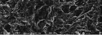

83 (a) (c) 71

, and surface (c) and fracture surface of a")
84 (b) (d) Figure 5.3- Scanning electron micrographs of the sandblasted surface (a) and the fracture surface of a porcelain bar (b), and surface (c) and fracture surface of a porcelain bar with YSZ coating (d). 72
85 For the zirconia substrate, the results showed a decrease in strength for the two highest stressing rates when compared to the control group. No significant differences were observed among stressing rates for the YSZ coated group. The dynamic fatigue parameters showed (Figure 5.4) very different trends for the uncoated (n=32) and coated groups (n=499). The strength values did not vary with stressing rates. Zirconia Average Fracture Strength (standard deviation-mpa) Stressing rates MPa/s Uncoated Coated (95.4) 1489 (131.4) (128.1) 1480 (133.4) (114.9) (136.8) (181.3) 1448 (141) Table 5.3- Mean flexural strength of uncoated and coated zirconia Parameters Weibull modulus (m) Characteristic Strength σ 63.2% Stressing rates (MPa/s) Uncoated Coated Uncoated Coated Table 5.4- Fracture strength characteristics of uncoated and coated zirconia according to stressing rates. 73

86 Figure 5.4- Dynamic fatigue data and fatigue of the uncoated and coated zirconia. 74

87 Figure 5.5- Scanning electron micrographs of the fracture surface of a sandblasted zirconia bar, and fracture surface of a zirconia bar with YSZ coating. 5.4 Discussion The development of new techniques or processes to improve mechanical reliability and increase the strength of ceramics is of great importance for biomedical applications. In particular, in dentistry where there is a great number of restorative ceramic materials being used that have relatively low strength and fracture toughness, such as machinable dental porcelains. [1, 2, 17] The use of the RF sputtering technique to deposit YSZ thin films on dental porcelain shows promising results. This technique could be applied to all ceramic materials in principal, in order to modify inherent surface flaws, suppress crack propagation, thereby improving fatigue behavior, fracture resistance, and 75
88 potentially having a broader application than developing new materials and material systems. In our study, the strength of YSZ modified porcelain significantly increased compared to the uncoated material. Since strength is likely to be related to microcracklike defects inherent to the microstructure of the processed porcelain, it is possible that the initial flaws or defects present in the samples might be blunted or passivated by the thin film, reducing the incidence of crack initiation. In addition to the flexural strength values, the characteristic strength values of the coated specimens were higher than the corresponding values of uncoated specimens for all stressing rates tested (Table 5.2). On the other hand, the Weibull modulus was similar in both groups, which lead us to conclude that the homogeneity of flaw distribution might not have changed, and similar critical flaws are still present in a certain volume of material. A relatively high Weibull modulus indicates better material reliability. [10, 12] Regarding the fatigue of modified and unmodified porcelain, other studies have reported this phenomenon when associated with glass-silicate materials, in which the characteristics of materials change over time under constant conditions.[14,18] It is apparent from the data for the porcelain substrate that slow crack growth is occurring for both the uncoated and coated porcelain, as strength values are dependent on stressing rate. It was assumed that the modifying films would improve the fatigue strength of the porcelain examined in this study. Many materials are subjected to stress corrosion, which is aggravated by the presence of surface flaws, and since the coating is probably modifying these flaws, stress corrosion resistance might be improved, preventing crack propagation. However, the 76
89 films did not exhibit a large improvement in fatigue characteristics. Even though the characteristic strength increased the susceptibility parameter for stress corrosion was similar for the uncoated and coated porcelain group. Previous studies have also shown that the properties of thin films can change over time. [7] It is therefore possible that a protective layer against water adsorption/absorption may prevent or lessen the severity of environment-assisted degradation of the zirconia films over time. SEM micrographs show a coherent interface between the YSZ thin film and the porcelain substrate. In addition, the columnar grain structure of the films can be seen. Because most cracks will propagate through grain boundaries, it is undesirable to have aligned grain boundaries parallel to the applied flexural forces. [20] For the zirconia substrate modified with the YSZ thin film a different strength behavior was observed when compared to that of the porcelain substrate. The strength of the coated group was lower than the uncoated when tested at the two highest stressing rates, however no differences were observed for the slower rates. Partially stabilized zirconia is a unique material since it undergoes a stress-induced phase transformation from a tetragonal crystal configuration to a monoclinic configuration (t m), which is usually responsible for its high strength. When a crack attempts to propagate through the material the transformation occurs, creating local compressive stress or a compliance region of fine microcracks at the tip of the propagating crack. Either phenomenon results in a reduction in crack tip energy, limiting further crack propagation. This is often referred to as transformation toughening. [9] However, as previously suggested, such transformation can be exacerbated by grinding, sandblasting of the substrate and also in 77
90 this case might be exacerbated by the presence of film stresses in the coating, which might have an effect in the metastability of the zirconia surface layer. Regarding the fatigue behavior of this specific construct the strength was the same regardless of the stressing rate tested, which would imply that strength degradation is not occurring in the coated groups. It is possible that the thin compressive layer induced in the surface region by the film changed the slow crack growth behavior of the surface flaws, leading to a threshold below, which no crack growth occurs. However, the analysis by means of dynamic fatigue testing is sensitive to the dependence of the strength on the stressing rate, therefore different testing methods should be used to further analyze the fatigue behavior of this construct. It is evident by this study that the effect of YSZ thin film deposition can be dependent on the substrate in question, especially one that has a toughening mechanism, such as zirconia. For substrates materials, such as porcelain, which have relatively low strength, it is crucial to try to develop a film that will indeed show a significant increase in the fatigue characteristics of the given material. 78
91 5.5 References 1. Mormann WH, Brandestini M, Lutz F, Barbakow F. Chairside computer-aided direct ceramic inlays. Quintessence Int, 1989;20: Fasbinder DJ. Clinical performance of chairside CAD/CAM restorations. J Am Dent Assoc, 2006; 137 Suppl:22S-31S. 3. Lawn BR. Fracture of brittle solids (2nd ed.), Cambridge University Press, Cambridge 1993; Kelly JR. Dental ceramics: current thinking and trends. Dent Clin North Am, 2004; 48: Pittayachawan P, McDonald A, Petrie A, Knowles JC. The biaxial flexural strength and fatigue property of Lava trade mark Y-TZP dental ceramic. Dent Mater, 2007;23: Guazzato M, Albakry M, Swain MV, Ironside J. Mechanical properties of In- Ceram Alumina and In-Ceram Zirconia. Int J Prosthodont, 2002; 15: Piascik JR, Thompson JY, Bower CA, Stoner BR. Evaluation of crystallinity and film stress in yttria-stabilized zirconia thin films. J Vac Sci Technol A 2005; 23: Hoshide T, Hayashi K, Saito T, Katsushi K, Inoue T. Mechanical properties of borosilicate glass coated with alumina by sputtering process. Mat Sci Res Int 1995; 2: Ruddell DE, Thompson JY, Stoner BR. Mechanical properties of a dental ceramic coated by RF magnetron sputtering. J Biomed Mat Res- Part A, 2000; 51: Della Bona A, Anusavice KJ, DeHoff PH. Weibull analysis and flexural strength of hot-pressed core and veneered ceramic structure. Dent Mater, 2003;19: Duckworth WH. Precise tensile properties of ceramic bodies. J Am Ceram Soc, 1951; 34: Weibull W. A statistical distribution function of wide applicability. J Appl Mech 1951, 18: Kelly RJ. Perspectives on strength. Dent Mater 1995; 11: Morena R, Beaudreau GM, Lockwood AL, Fairhurst CW. Fatigue of dental ceramics in a simulated oral environment. J Dent Res 1986; 65:
92 15. Evans AG. Slow crack growth in brittle materials under dynamic loading conditions. Int J Frac. 1974; 10: Ritter JE, in Fracture Mechanics of Ceramics (Plenum Publishing Co., NY, 1978) p Attia A, Abdelaziz KM, Freitag S, Kern M. Fracture load of composite resin and feldspathic all-ceramic CAD/CAM crowns. J Prosthet Dent. 2006;95: Teixeira EC, Piascik JR, Stoner BR, Thompson JY. Dynamic fatigue and strength characterization of three ceramic materials. J Mater Sci Mater Med Rekow D, Thompson VP. Engineering long term clinical success of advanced ceramic prostheses. J Mater Sci Mater Med. 2007;18: Ruddell DE, Thompson JY, Stoner BR. The effect of deposition parameters on the properties of yttria-stabilized zirconia thin-films. Thin Solid Films 2003, 445: Quinn JB, Quinn GD, Kelly JR, Scherrer SS. Fractographic analyses of three ceramic whole crown restoration failures. Dent Mater 2005; 21: Piascik JR, Thompson JY, Bower CA, Stoner BR. Stress evolution as a function of substrate bias in rf magnetron sputtered yttria-stabilized zirconia films. J Vac Sci Technol A 2006; 24: Drouin JM, Cales B, Chevalier J, Fantozzi G. Fatigue behavior of Zirconia hip joint heads: Experimental results and finite element analysis Journal of Biomedical Materials Research,1997 : 34,
93 Chapter 6 Effect of YSZ thin film coating thickness on the strength of a ceramic substrate This chapter addresses the possible effect of surface modification with a yttriastabilized zirconia (YSZ) thin film of different thickness on the strength of a machinable dental ceramic. According to the sputtering rate deposition coating thickness can be varied. 6.1 Introduction A number of factors can contribute to material performance when used for different applications, including the material s strength. Defects and flaws that may initiate and grow at the microscopic level have been shown to significantly control strength characteristics.[4-5] Using fractography analysis, previous studies concluded that dental ceramics are inherently fragile in tension. It has been demonstrated that cracks usually originate at the internal surface of clinical failed all-ceramic crowns, where the greatest tensile stress occurs.[6-8] In an attempt to address this problem some studies have focused on surface modification procedures and techniques. The apparent fracture resistance of glassceramics and survival rates of all-ceramic crowns bonded with resin cement was
94 increased compared with those bonded with acid-base cements.[9-12] Other techniques beyond the use of resin luting agents, include: ion exchange [13-15], thermal tempering [16], machining and polishing, [15, 17-18] and application of a glazing layer [19]. Surface compressive stress can be created on a range of ceramic materials following some of these treatment processes, and can increase the resistance to crack initiation and growth.[1, 18, 20] Ruddell et al. [21] showed that the mechanical properties of a dental ceramic can be improved by the deposition of a thin film of gold or aluminum using a sputtering process. Throughout this process flaws and/or cracks in the substrate can be coated or filled, and might become blunted. The flaw size is reduced and the effective radius of curvature is increased, in this manner making crack propagation more difficult. Sputtering, as discussed previously is a simple deposition process that can be used with different types of materials, including non-conductive materials such as ceramics. Among ceramic materials, partially stabilized zirconia has the most attractive properties, which include: relatively higher toughness, capacity of transformation toughening, low thermal conductivity, and good wear resistance properties.[23] In a study by Piascik et al., it was shown that yttria-stabilized thin films can be produced by a sputtering process, and these films are typically under a compressive stress, depending on the deposition parameters.[24] The creation of a compression layer composed by a tougher material, such as YSZ and acting against the tensile stress [25], i.e. on the inner surface of a crown may help to strengthen the material, improving overall fracture resistance. The aim of this study was 82
95 to assess the effect of YSZ thin films on the flexural strength of a dental ceramic and to test the hypothesis that its strength is dependent on the thin film coating thickness. 6.2 Experimental Fifty bars (2mm x 2mm x 15mm) were cut from ProCAD (Ivoclar-Vivadent) blocks. Specimens were wet-polished through 1200-grit SiC abrasive. One surface of each bar was sandblasted with 50µm Al 2 O 3 abrasive (0.34MPa). Specimens were further modified through the deposition of a sputtered YSZ thin film on the sandblasted surface. The porcelain bars were randomly divided into one control group (uncoated) and four experimental groups (n = 10 per group), according to YSZ thin film thickness: 1μm, 3μm, 5μm, and 7μm. Depositions were performed using the same system described in the other chapters. The porcelain bars were placed in a jig (10 bars at each time) directly above a sputtering gun (US Gun, San Jose, CA). Depositions were performed at working pressure of 15mT, 150ºC temperature, and a 30:1 Ar/O 2 ratio of oxygen input flow rate. In order to produce the different thin film thicknesses wanted sputtering times were varied from 2.5 to 17.5 hours (deposition rate 0.4 μm/h). After the depositions were performed the specimen thickness was checked using a profilometer. Forty-eight hours after coating, each specimen was tested in three-point bending (span= 10mm) in a servo-electric mechanical testing system (Evolution, MTS, Minneapolis, MN) using an environmental chamber filled with deionized water (DI) at 37 o C. Fracture surfaces of selected specimens (half of each group) were also examined using scanning electron microscopy, and the film thickness for each group measured. 83
96 6.3 Results Mean flexural strength (MPa) and standard deviation of the uncoated, 1μm, 3μm, 5μm, and 7μm YSZ thin film coated groups were respectively: (5.1), (7.6), (9.5), (8.8), and (9.5). 140 Flexural Strength (MPa) Thin-film thickness (micron) Figure 6.1- Effect of YSZ thin film thickness on the mean flexural strength of modified porcelain bars. The results demonstrate that the highest mean strength value was observed for the group coated with a 3μm YSZ thin film. The 5μm group was also statistically significantly different from the control group (uncoated), but not from the 1μm and 7μm coated groups. A slight increase in strength is shown for specimens coated with a 1μm thick thin film, but this was not statistically different than the uncoated control group. An increase in the thin film thickness didn t necessarily result in an increase in the flexural strength of the substrate. The error bars shown in Figure 1 correspond to the 95% 84

97 confidence intervals for each group. SEM micrographs of each coating thickness are shown in Figures 6.2 to 6.5. Figure 6.2- SEM micrograph (2,500X) representative of 1μm thick film on the fracture surface of the porcelain substrate. 85
 representative of 3μm thick film")
98 Figure 6.3- SEM micrograph (2,500X) representative of 3μm thick film on the fracture surface of the porcelain substrate. 86
 representative of 5μm thick film")
99 Figure 6.4- SEM micrograph (2,500X) representative of 5μm thick film on the fracture surface of the porcelain substrate. 87

100 Figure 6.5- SEM micrograph (2,500X) representative of 7μm thick film on the fracture surface of the porcelain substrate. 6.4 Discussion This study shows that the flexural strength of a dental ceramic can be improved by the deposition of a YSZ thin film, using radio frequency magnetron sputtering. Other studies have shown similar results using different substrates and testing procedures.[21,22] It is important that laboratory strength tests simulate the failure mechanisms[26] and environmental conditions[1,2] normally encountered in a clinical situation. In this study, all specimens were tested in DI water at a controlled temperature (37 C). 88
101 It is also known that flaws in materials under stress can react with certain environments resulting in bond rupture and flaw growth at stresses well below the nominal strength of the material. Stress corrosion caused by water is particularly effective at enhancing fracture in many brittle materials, as shown in the previous chapter. The environment can have an effect not only on substrate but also on a sputtered thin film. It has been reported that an increase in compressive stress was observed in sputtered YSZ thin films upon exposure to ambient conditions (75% relative humidity), specially in the first two hours after exposure. This was believed to be caused by water absorption in the defects (porosity) within the films.[24] For all tested groups, the film/substrate interfaces appeared to be relatively coherent and free of interfacial defects (Figure 2). No significant loss in adhesion was noticed between the film and the substrate in the specimens examined using SEM. The highest increase in fracture strength on the porcelain was 21.7% for the group coated with the 3µm thick film. A similar increase was observed for the 5µm group. However, for the thickest film deposited (7µm group), the mean flexural strength value observed was similar to the control group. Even though the strength of the substrate was affected by the thin film coating, one would expect that as film thickness is increased, the overall film volume increases. This perhaps allows the applied load to be distributed over a greater volume (i.e., potentially more energy can be absorbed). On the other hand, a thicker film might generate a larger force at the interface, being more subject to cracking and delamination during loading. This can be assumed because for a given film microstructure is expected that film stress is the same 89

102 independent of thickness. Figure 3 shows a random example of a fractured porcelain bar and slight gap formation below the YSZ/ceramic interface in the 7µm group. It is also possible for a thicker film to have a higher volume fraction of porosity than the thinner films, decreasing their bulk properties. Figure 6.6. SEM micrograph of a fracture surface showing (A) YSZ thin film structure (7μm), and (B) porcelain substrate. Arrows show small gaps at the film/substrate interface. Residual stresses can also play an important role in the strength of ceramic materials.[18] These stresses in the thin film coatings can be influenced by the mismatch in thermal coefficient of expansion between the thin film and the substrate material or by intrinsic stress from the deposition process. In this study, the maximum deposition 90
103 temperature was 150 C. The YSZ material used in this study consists of a lower coefficient of thermal expansion (10.3ppm/ºK) than the porcelain used as the substrate material (17.0ppm/ºK). The thermal stress generated on the film during cooling from the deposition temperature can be calculated by [27]: σ th = E f (α f -α s )(T s -T a ) (2) where E f is the film Young s modulus, α f and α s are the average coefficient of thermal expansion for the film and the substrate, T s and T a are the substrate temperature during deposition and the ambient temperature during testing. The relationship indicates that a compressive thermal stress of ~175MPa can be generated during cooling. By evaluating the thermal stress calculation, it is assumed that compressive residual thermal stresses could have been induced into the thin film.[27] The same effect has been observed for glazing and staining materials in relation to core materials used for all-ceramic restorations.[19,28,29] Compressive residual stresses can increase the loading capability and the usable fracture strength of these modified materials.[22] Another possible strengthening factor that can be involved in the effect that the film has on the fracture strength of the porcelain relates to modification of surface flaws and/or cracks. Ruddell et al. suggested crack blunting or bridging as a possible reason for strengthening of porcelain by depositing gold and aluminum thin films.[21] In another study, where alumina bars were modified with YSZ thin films, no significant changes in the specimen flexural strength were observed among coated groups even though different deposition parameters were used, producing films that were structurally different. 91
104 However, higher flexural strength values were observed between the uncoated and coated groups. [30] It is reasonable to believe that in the present study, modifying thin films could also have promoted surface flaw modification, increasing the measured strength of coated specimens. However, further studies are necessary in order to understand and measure the effects of residual stresses states in the film-substrate construct. Implementing this methodology as a treatment technique into the dental laboratory /clinical settings might increase the overall survival rates of all-ceramic restorations, and also make low-strength ceramics, such as porcelain, more reliable for high stress bearing areas applications. Based on the results of this study we can conclude that RF sputtering of YSZ thin films can be used to increase the flexural strength of dental porcelain. However, film thickness alone does not appear to control increases in the flexural strength of the modified substrate. 92
105 6.5 References 1. Lawn BR. Fracture of brittle solids (2nd ed.), Cambridge University Press, Cambridge 1993; Anusavice KJ, Lee RB. Effect of firing temperature and water exposure on crack propagation in unglazed porcelain. Journal of Dental Research 1989; 68: Taskonak B, Mecholsky JJ, Anusavice KJ. Residual stresses in bilayer dental ceramics. Biomaterials 2005; 26: Ritter JE. Predicting lifetimes of materials and material structures. Dental Materials 1995; 11: Kelly RJ. Perspectives on strength. Dental Materials 1995; 11: Thompson JY, Anusavice KJ, Naman A, Morris HF. Fracture surface characterization of clinically failed all-ceramic crowns. Journal of Dental Research 1994, 73: Quinn JB, Quinn GD, Kelly JR, Scherrer SS. Fractographic analyses of three ceramic whole crown restoration failures. Dental Materials 2005; 21: Kelly JR, Campbell SD, Bowen HK. Fracture-surface analysis of dental ceramics. Journal of Prosthetic Dentistry 1989; 62: Burke FJT. Maximizing the fracture resistance of dentine-bonded all-ceramic crowns. Journal of Dentistry 1999; 27: Rosenstiel SF, Gupta PK, Van der Sluys RA, Zimmerman MH. Strength of a dental glass-ceramic after surface coating. Dental Materials 1993; 9: Malament KA, Socransky SS. Survival of Dicor glass-ceramic dental restorations over 14 years: Part I. Survival of Dicor complete coverage restorations and effect of internal surface acid etching, tooth position, gender and age. Journal of Prosthetic Dentistry 1999; 81: Pagniano RP, Seghi RR, Rosenstiel SF, Wang R, Katsube N. The effect of a layer of resin luting agent on the biaxial flexure strength of two all-ceramic systems. Journal of Prosthetic Dentistry 2005; 93: Fischer H, Marx R. Improvement of strength parameters of a leucite-reinforced glass ceramic by dual-ion exchange. Journal of Dental Research 2001;80:
106 14. Fischer H, Brehme M, Telle R, Marx R. Effect of ion exchange of glazed dental glass ceramics on strength parameters. Journal of Biomedical Materials Research 2005; 72A: Giordano RA, Campbell S. Flexural strength of feldspathic porcelain treated with ion exchange, overglaze, and polishing. Journal of Prosthetic Dentistry 1994, 71: Anusavice KJ, Shen C, Vermost B, Chow B. Strengthening of porcelain by ion exchange subsequent to thermal tempering. Dental Materials 1992; 8: Albakry M, Guazzato M, Swain MV. Effect of sandblasting, grinding, polishing and glazing on the flexural strength of two pressable all-ceramic dental materials. Journal of Dentistry. 2004;32: Samuel R, Chandrasekar S. Effect of residual stresses on the fracture of ground ceramics. Journal of the American Ceramic Society 1989; 72: Fairhurst CW, Lockwood PE, Ringle RD, Thompson WO. The effect of glaze on porcelain strength. Dental Materials 1992; 8: Denry LL, Rosenstiel SF, Holloway JA, Niemiec MS. Enhanced chemical strengthening of feldspathic dental porcelain. Journal of Dental Research 1993; Ruddell DE, Thompson JY, Stoner BR. Mechanical properties of a dental ceramic coated by RF magnetron sputtering. Journal of Biomedical Materials Research- Part A. 2000; 51: Mecholsky JJ, Tsai YL, Drawl WR. Fracture studies of diamond films on silicon. J Appl Phy 1992; 71: Hannink RH, Kelly PM, Muddle BC. Transformation toughening in zirconiacontaining ceramics. Journal of American Ceramic Society 2000;83: Piascik JR, Thompson JY, Bower CA, Stoner BR. Evaluation of crystallinity and film stress in yttria-stabilized zirconia thin films. J Vac Sci Technol. A 2005; 23: Cattell MJ, Clarke RL, Lynch EJ. The biaxial flexural strength and reliability of four dental ceramics Part II. Journal of Dentistry 1997;25: Bhamra G, Palin WM, Fleming GJP. The effect of surface roughness on the flexural strength of an alumina reinforced all-ceramic crown material. Journal of Dentistry 2002; 30: Thornton JA, Hoffman DW. Stress-related effects in thin films. Thin Solid Films, 1989;171:
107 28. Isgro G, Pallav P, van der Zel JM, Feilzer AJ. The influence of the veneering porcelain and different surface treatments on the biaxial flexural strength of a heat-pressed ceramic. Journal of Prosthetic Dentistry 2003;90: Williamson RT, Kovarik RE, Mitchell RJ. Effect of grinding, polishing, and overglazing on the flexure strength of a high-leucite feldspathic porcelain. International Journal of Prosthodontics 1996;9: Ruddell DE, Thompson JY, Stoner BR. The effect of deposition parameters on the properties of yttria-stabilized zirconia thin-films. Thin solid Films 2003,
108 Chapter 7 Effect of a multilayer film on the fracture behavior of porcelain Recent research has shown that the application of specific thin films can enhance the materials properties of a construct. In this chapter, a multilayer film with high and low modulus layers is proposed and its effect on the strength and fatigue parameters of a brittle ceramic substrate (dental porcelain) is investigated Introduction Among the three main categories of biomaterials: metals, polymers, and ceramics, the last is an attractive choice for prostheses, mostly because of excellent biocompatibility and, in some applications, such as dental restorative prosthetics, esthetics.[9] Most biomaterials require excellent long term clinical performance to be considered viable commercial alternatives. However, studies have shown high clinical failure rates over moderate service life for many bioceramics used in medicine and especially dentistry. [10] In order to increase the performance of these materials the application of thin film coatings has been suggested as discussed in the previous chapters.[11] Previous reports have shown that the mechanical properties of a dental ceramic can be improved by the deposition of a thin film of gold, aluminum, and zirconia using a sputtering process.[11, 12] As briefly discussed in chapter 6, flaw modification and residual stresses may be possible strengthening mechanisms when
109 single-layer coatings are applied. Multilayer or laminate structures can also be used to combine the best aspects of the constituent layers in order to achieve a more useful modified material with even better mechanical properties. Multilayered materials, such as alumina-zirconia composites developed by the introduction of fine zirconia particles in a polycrystalline alumina matrix have extensive structural application due to their robust mechanical properties. [5,6] Koehler showed that a laminate structure composed of two metal thin-layers has higher strength than the individual metals alone.[7] The concept of a multilayered structure has been explored for years, not only in the form of bulk substrate materials, but also as complex thin film coatings. However, even though laminate structures of thin films have been studied since the seventies, no study has focused on the application of a ductile/brittle film on the mechanical properties of a ceramic substrate, which can potentially be used for biomedical applications. It is assumed that the deposition of a multilayered film of this type will enhance the strength, and hopefully the fatigue resistance, of a brittle substrate. For the brittle layers in the multilayered thin film proposed in this study, yttria stabilized zirconia (YSZ) is still used as the material of choice, since the conditions for deposition and its effect as a single layer have been investigated previously.[4] However, one of the main disadvantages of ceramic thin films, just like for bulk ceramic materials, is their brittleness. To overcome the brittleness of a pure ceramic film, a ductile layer is introduced. For the ductile layers, a bio-inert and bio-compatible polymer, parylene, is utilized. Parylene also can be deposited in completely conformal uniform thickness, which is desirable. This is achieved by a unique vapor deposition polymerization process. The advantage of this process is that the coating forms from a gaseous 97

110 monomer without an intermediate liquid stage. As a result, component configurations with sharp edges, points, flat surfaces, crevices or exposed internal surfaces are coated uniformly without voids. Parylene is FDA-approved and resistant to moisture, and chemicals. With this in mind and with the fact that a protective layer against water adsorption/absorption may prevent or lessen the severity of environment assisted degradation of the zirconia films and ceramic substrate over time, parylene is a suitable choice for initial testing. The hypothesis of this study was that proper choice of coating material and structure can result in a significant improvement in the initial strength and susceptibility to strength degradation, of a modified brittle substrate. Figure 1 displays a representative multilayer sample of alternating YSZ and parylene thin films. Figure SEM micrograph of a multilayer film consisting of alternating layers of YSZ and parylene. 98
111 7.2. Experimental The experimental procedure in this chapter can be divided into two parts: 1- analysis of short term strength of porcelain modified by different coatings 2- dynamic fatigue analysis of a multilayer construct Part 1-Experimental sequence and results Fifty samples (porcelain bars) were prepared for thin film deposition in the same manner as described in previous chapters. The porcelain bars were then randomly divided into one control group (uncoated) and four experimental groups (n= 10 per group), according to film depositions: 10µm yttria-stabilized zirconia (YSZ) thin film, 10µm parylene thin film, 9.75µm YSZ µm parylene film, and multilayered film (5 alternating layers of 1.25µm YSZ µm parylene). YSZ depositions were performed using the same system and process described in chapter 4 and under the same depositions conditions (working pressure of 15mT, 150ºC temperature, and a 30:1 Ar/O 2 ratio of oxygen input flow rate). The deposition times varied in order to obtain the different film thicknesses. In order to produce the parylene-c layers, a unique vapor deposition polymerization process was used (Labcoter 1, model PDS 2010, Specialty Coating Systems, Indianapolis, IN), and is shown in Figure 7.2. Parylene was deposited from the vapor phase at a pressure of 100 mt. At this pressure the mean free path of gas molecules are on the order of 0.1cm, creating a conformal coating. The deposition was carried out in four steps: (1) vaporization of a solid dimer (di-paraxylylene) at 150 C, (2) quantitative cleavage (pyrolysis) of the dimer at the two methylenemethylene bonds to yield a stable monomeric diradical (paraxylylene), (3) monomer enters room temperature deposition chamber where it simultaneously adsorbs and 99
112 polymerizes on the substrate, forming a transparent film, and finally (4) the substrate is baked at 200 C in O 2 atmosphere for two hours to complete cross-linking (increases hardness by an increase in density and crystallinity).[8] Figure 7.2- Sequence used in vapor-depostion process of parylene and representation of its polymer structure. After deposition of the thin films, each specimen was tested in three-point bending (span= 10mm) in a servo-electric mechanical testing system (Evolution, MTS, Minneapolis, MN) using an environmental chamber filled with deionized water (DI) at 37 o C. The results of the mechanical tests are shown on Table 7.1, below: Groups (Porcelain substrate) n Strength (SD) Control (uncoated) (5.0) a 10 µm YSZ (6.7) b 10µm parylene (5.6) b 9.75µm YSZ µm parylene (6.2) b Multi-layer (6.9) c *Similar superscript letters indicate that groups are not statistically different (p>0.05). Table 7.1- Flexural strength (MPa) of porcelain coated with different thin-films. 100

113 The results showed (Table 7.1) a significant increase in strength for all groups when compared to the uncoated control group. An increase of ~11% to ~13% in the material s flexural strength was observed when a monolayer thin film of YSZ and parylene, respectively was applied on the substrate surface. The most significant increase (~32%) was observed for the substrate coated with the multilayered thin film (5 layers of 1.25µm YSZ and 0.75µm parylene). The mean strength value for this group was significantly different when compared to the other coated groups. Figures 7.3 through 7.6 show the microstructure of the deposited films on the ceramic substrate. A cohesive interface between the deposited films and the porcelain substrate was observed. YSZ film Substrate Figure 7.3-SEM micrograph of the fracture surface of the ceramic substrate coated with 10µm YSZ thin film. 101


114 Parylene film Figure 7.4- SEM micrograph of the fracture surface of the ceramic substrate coated with 10µm parylene thin film. Parylene layer YSZ layer Figure 7.5- SEM micrograph of the fracture surface of the ceramic substrate coated with 9.75µm YSZ µm parylene. 102

115 Parylene layer YSZ layer Figure 7.6- SEM micrograph of the fracture surface of the ceramic substrate coated with 5 layers of 1.25µm YSZ µm parylene Part 2- Experimental sequence and results To evaluate the basic fatigue parameters of dental porcelain modified by deposition of a YSZ-parylene thin-film, and compare the data to that of an unmodified control (porcelain, sandblasted), 200 bars were prepared in the same manner as described before. Half of the specimens were further modified via deposition of 5 alternating layers of 1.25µm yttria-stabilized zirconia (YSZ) µm parylene thinfilm on the sandblasted surface. Depositions were performed using an RF magnetron sputter system (working pressure of 15mT, 150ºC, 30:1 Ar/O 2 gas ratio) for YSZ layers and a vapor deposition process for the parylene layers. Specimens were tested at different stressing rates: 5.0, 0.1, and 0.01 MPa/s (n=25/group) in DI water (37ºC), and inert strength was determined in air (25ºC, 70MPa/s). All strength measurements were carried out by three-point bending in a servo-electric test system (MTS- Evolution), with the modified side being placed in tension as shown in chapter
116 The flexural strength of the coated group was significantly higher than the uncoated group at all stressing rates. Figure 7.7 shows the average flexural strength and 95% confidence of intervals for each group: % CI - Strength coated uncoated Stressing rate (MPa/s) Figure 7.7- Flexural strength and 95% confidence intervals for uncoated (control) and coated (porcelain coated with YSZ thin film) groups. The fatigue parameters n and lnb were calculated by linear regression of dynamic fatigue data (Figure 7.8). For the uncoated group, n=37 and lnb=18mpa 2 s, and n=20 and lnb=12mpa 2 s for the coated group. Weibull analysis was also performed showing that the characteristic parameter (σ o ) was 133 and 161MPa for the uncoated and coated group respectively. 104
117 Ln Flexural Strength (MPa) Coated n=20 lnb=12 (r 2 = 0.99) Uncoated n=38 lnb=18 (r 2 = 0.93) Ln Stressing rates(mpa/s) Figure 7.8- Dynamic fatigue data of the uncoated and coated (multilayer film) porcelain. 7.3 Discussion Factors involved in the strengthening effect In this study a multilayered thin film, consisting of alternating layers of YSZ and parylene was fabricated and evaluated. When a multi-layered coating is applied to a brittle substrate, the strength of the composite is increased significantly when compared to modification by a single-layer structure of either materials utilized individually. Three mutual mechanisms are proposed for the strengthening effect caused by the thin film deposition: film stress, flaw modification, and a mechanism related to film structure Film stress Film residual stresses may inhibit or enhance cracking in the substrate, depending on whether these stresses are compressive or tensile. Because cracks grow 105
118 under tension, the applied tensile stresses must overcome the residual compression in the surface (pre-stressed film) of the substrate in order to cause fracture. Stress Analysis For the stress analysis, a multilayer film was deposited on a silicon wafer. The sample was measured before deposition (initial bow) and after deposition for thin film stress calculations, using a Flexus (Tencor FLX-2320, Milpitas, CA) instrument. The stress in the thin film was calculated from the radius of curvature of the substrate using the Stoney equation: σ f = - (E s t s / 6(1-ѵ s )t f )(1 / R a 1/ R b ) where E s /(1-ѵ s ) is the biaxial modulus of the substrate (1.8 GPa), t s and t f are the thickness of the substrate and deposited film, and R a and R b are the substrate radius of curvature measured before and after film deposition. The measured stress represents the total internal stress in the film (intrinsic + thermal). Intrinsic stresses (σ i ) are formed due to accumulation of crystallographic flaws that develop during film growth. Thermal stresses (σ T ) are due to the difference in the coefficient of thermal expansion between the film and the substrate. The thermal stress in the film can be calculated using the equation below: σ T = E f (α f -α s )(T s -T a ) where E f is the film Young s modulus, α f and α s are the average coefficient of thermal expansion for the film and the substrate, T s and T a are the substrate temperature during deposition and the ambient temperature during testing. For a multilayered system, it is assumed that we have a tensile film according to the measurements acquired from the film deposited on the Silicon wafer. However, one should be reminded that our construct has porcelain as the substrate. Based on the 106
119 wafer bow measurement of a multilayer film on Si, an average intrinsic stress value for the YSZ layer and for the parylene layer was estimated and applied in order to calculate the total stress on the multilayer film when deposited on porcelain. The table below shows the materials properties used for the stress calculation: Material CTE( 0 C) Modulus(MPa) Parylene 3.50E Porcelain 1.70E YSZ 1.00E Silicon 3.00E Table 7.2-Material properties used in the stress analysis. The total stress (σ) for the multilayer film on the silicon wafer is known. The thermal stresses, incremental (σ Ti ) and cumulative (σ Tc ), can be calculated using the equation shown above. The cumulative stress is defined as the total stress that the film sees following the application of the last layer. The deposition temperature of the YSZ thin film was C and the temperature during the stress measurement was 25 0 C (ΔT=125 0 C). For the parylene layer the substrate temperature was C, therefore the ΔT used was C post annealed. Because the total stress is known and the thermal stress can be calculated, it is also possible to calculate the intrinsic incremental (σ Ii ) and intrinsic cumulative stress (σ Ic ) associated with each layer (n=10 layers). The equations below show the relationship between incremental and cumulative stresses: i. ii. Ti i Tc i Tc Ic iii. Ic Ii i i 107
120 where t is the film thickness, t i is incremental thickness, and n is number of layers. Table 7.3 shows the stress values relative to each layer when the multilayer film is deposited on a silicon substrate. It can also be observed when plotting the data, that the total stress value becomes less compressive as layers are added (Figure 7.9). Intrinsic Intrinsic Thermal Thermal Total Layer/Stress incremental cumulative incremental cumulative measured 1-PSZ Layer 2 (PA) PSZ Layer 4 (PA) PSZ Layer 6 (PA) PSZ Layer 8 (PA) PSZ Layer 10 (PA) Table 7.3- Stress values (MPa) for a multilayer film on a silicon wafer. Negative sign represents compressive values. Figure 7.9- Representation of film stresses values on Si as a function of number of layers. 108
121 The average intrinsic stress for the parylene layer (σ Ii= -9) was calculated based on the intrinsic incremental stress calculation performed above (Layer 2, Layer 4, Layer 6, Layer 8, Layer 10). The average intrinsic incremental stress for the YSZ layer (σ Ii= -103) was calculated in the same way based on the values of layers 3-PSZ, 5-PSZ, 7-PSZ, 9-PSZ, shown in Table 7.3. The intrinsic stress of the 1-PSZ is different than the average stress, because the first layer is deposited on porcelain. Therefore, it is possible to calculate the intrinsic cumulative stresses and consequently the total stress, based on the same relationship equation (i, ii, iii) shown before. Intrinsic Intrinsic Thermal Thermal Total Layer/Stress incremental cumulative incremental cumulative measured 1-PSZ Layer 2 (PA) PSZ Layer 4 (PA) PSZ Layer 6 (PA) PSZ Layer 8 (PA) PSZ Layer 10 (PA) Table 7.4- Stress values (MPa) for a multilayer film on a porcelain bar. Negative sign represents compressive values. 109
122 Figure Representation of stresses values of a film on a porcelain substrate as a function of number of layers. Force Analysis In order to analyze the effect of film stress on the failure strength of a coated specimen, a model for fracture behavior in thin film coated porcelain, based on the force generated by film stress, was used. This model is based on the following assumptions: i) Specimens were tested in 3-point bending, whereby a surface crack experiences an opening loading mode, where the principal load is normal to the crack plane (unidirectional force), and assuming isotropic linearelastic material behavior. (Figure 7.11) 110
 Surface flaw is present having a semi-circular shape (half-penny shaped form). (Figure 7.12) Figure 7.")
. iii) Deposited film has a plane stress. Stresses that are parallel to the applied force will dominate in this mode.")
123 Figure 7.11-Representation of opening mode applied to a crack (horizontal blue arrows). ii) Surface flaw is present having a semi-circular shape (half-penny shaped form). (Figure 7.12) Figure Representation of a surface flaw in a specimen under the influence of an applied stress (represented by arrow in a three pointbending test configuration), and cross-sectional area (half-penny). iii) Deposited film has a plane stress. Stresses that are parallel to the applied force will dominate in this mode. The principal role of the film is to exert an opening or closing force on the surface flaws (uniform distribution of stress). 111
124 Figure Representation of compressive film stresses (arrows) acting on a surface defect. The force generated by film stress was calculated. For a uniformly deposited film, according to assumption iii) it can also be claimed that the force generated by the film is also uniformly distributed. In this analysis the force generated by the film on a projected defect area can be calculated. Film stress generates a force over a given area (A). Stress in an object is defined as the force per unit area: σ f =F f /A. Assuming a cross-sectional area relative to the thickness of the film and total width of a perfect specimen with no surface flaws. The area in question is: A=thickness (t) X width (w). The total film thickness varies (1.25, 2, 3.25, 4, 5.25, 6, 7.25, 8, 9.25,10E-06 m). Width of the specimen (bar) m. σ f= stress varies (total compressive previously calculated film stress on porcelain was used to determine the generated force). 112
125 Figure Representation of calculated compressive force as a function of film thickness in a perfect specimen (no flaws). It can be observed through Figure 7.14 that the force increases with film thickness and that the force generated by the parylene layers is minimal compared to the one from the zirconia layers. However, the magnitude of the force generated by the film is very small if a perfect specimen is considered. The film acting alone without the presence of flaws or defects is not enough to make a difference in the strength of the material, due to the fact that the thickness of the film is much smaller compared to the thickness of the substrate. Therefore, the effect of the force generated by film stresses correlates with the presence and size of surface flaws. In order to calculate the effect of different flaw sizes the same assumption applied for the force analyses are used here. The area correlates with the force and consequently the stress and ultimate strength of the material. The force generated by the film stresses are depedent on the film thickness, film stress, and flaw size. In the case of a semi-circular surface flaw for example, the 113
 film substrate c Figure 7.")

.")
 24MPa 0 12MPa 5MPa no")
 23MPa 9 PSZ 94MPa 47MPa Layer 10 (PA) Figure 7.")
126 force generate by the film will have an effect on the strength according to a given area: A=пc 2 /2.(Figure 7.15) film substrate c Figure Schematic of cross-sectional area (A=shaded region) for a semi-circular surface flaw of size c. Therefore, the increase in strength can be shown according to the different flaw sizes (Figure 7.16). Contribution of the film force to the material's strength (MPa) for different flaw sizes 100 um 50 um Strength (MPa) 24MPa 0 12MPa 5MPa no film 1 PSZ Layer 2 (PA) 3 PSZ Layer 4 (PA) 5 PSZ Layer 7 PSZ 6 (PA) Film Layers Layer 8 (PA) 23MPa 9 PSZ 94MPa 47MPa Layer 10 (PA) Figure Representation of the increase in strength for different flaw sizes of 100µm, 50µm, and 25µm. 114
127 In the absence of flaw modification or considerations related to the multilayer construct, the change in strength from the uncoated to the coated group can be related to the force created by the film and exerted on the substrate surface. The change in strength of a construct with a critical flaw size of 100 µm is shown as ~23%. This increase can be correlated with the actual increase in strength shown by the measured data. It can be recalled that the multilayer film showed an increase of ~32% when compared to uncoated group (100MPa). It might be assumed that the flaw responsible for failure in this construct would be close to a 100 µm. Film stresses can be considered as one of the contributing mechanisms for the change in strength of this system, due to the fact that film stress will act on a defect or flaw. The applied stress in the surface region can decrease, making crack propagation more difficult. However, other factors need to be taken into consideration besides residual stresses, and these can change the fracture behavior of the material. A change in a component geometry, for example may also remove unwanted stress concentration, which can be benneficial for the system Flaw modification/flaw tolerance If the basic equation between strength (σ) and fracture toughness (K IC ) is considered, it is clear that multiple factors can have an influence on the change in the strength of a material: IC where Y is a geometry factor that accounts for flaw shape, location, and loading geometry, and c is the size of the flaw. For a semicircular surface crack subjected to a far field stress, that is free of residual stress and that is small relative to the thickness of the cross-section, Y is This value of Y has been applied to different ceramics, and is generally accepted. [19] 115
 the critical flaw can be calculated to be ~55.4μm in comparison to ~93.4μm for the uncoated group.")
128 Therefore if we take into consideration that the fracture toughness of the porcelain used is 1.2 MPam 1/2, and the average strength is known to (100MPa for the uncoated group and 130MPa-coated) the critical flaw can be calculated to be ~55.4μm in comparison to ~93.4μm for the uncoated group. It might be assumed that flaws in the surface are filled or partially filled by the coating due to the nature of the sputtering process used. It is known that the size of the flaws is related to a decrease or increase in strength. Perhaps the initial geometry of the flaw has also changed. The flaw might be less deep, and the crack tip radius of curvature might have increased, facilitating an increase in strength. (Figure7.17) However, the average roughness of the coated group was similar to the uncoated group when measured by a stylus profilometer (~2.0μm). Atomic force microscopy might be a more useful tool to study the effect of this film on the topography of the material s surface, since the scale of the measurements will be more accurate in relation to the topography of the coating. Modified flaw Initial flaw Substrate Figure Schematic of a multilayer film deposited on a ceramic substrate. Another approach that can be considered, regarding the improvement in strength of the multilayer system, is related to a change in the fracture toughness of 116
129 the material, or apparent fracture toughness of the thin film modified construct. The fracture toughness value of the material reflects the ability of a material to resist unstable crack propagation, and is considered an intrinsic material property. However, it might be possible that the apparent toughness of the material has increased due to the application of the coating. Therefore, regardless of a change in the flaw size within the material, the strength would increase. The work of fracture is related to the stress-strain behavior of the material, and can be calculated as the area below the stress-strain curve. A slight shift in the stress-strain curve for the coated group when compared to the uncoated group can be observed. The slope for the uncoated group was determined to be 10.8 GPa (SD-2.5) and the strain (SD-0.002), while that of the coated was 12.6 (2.4) GPa and (0.003). An example of the stress-strain curve for an uncoated (sandblasted porcelain) and coated (porcelain with YSZ thin film) specimen is shown in the figure below (Figure7.18). A change in the strain absorption capacity can be seen for the coated group when compared to the uncoated group. In order to quantify the change in the mechanical behavior of the material, the fracture toughness can be calculated by measuring the size of the critical flaw associated with the fracture strength value. 117

130 Figure Example of stress-strain curve of uncoated (sandblasted porcelain), and coated specimens (porcelain coated with YSZ thin film). By analyzing the fracture surfaces of the tested specimens under optical microscopy it can be observed that the critical flaw size for an uncoated specimen was 122 μm (Figure 7.19) and the coated group was 129μm. Both groups displayed similar flaw sizes (c=ab 1/2 ), which were calculated based on the parameters (a) and (2b) for a semi-elliptical flaw shown in Figure However, when calculating the fracture toughness of the material that estimated for the uncoated porcelain was 1.3 MPam 1/2, while that for the coated group was 2.0 MPam 1/2. The apparent toughness is the fracture toughness calculated from the test data when considering the coated specimen as homogenous. The apparent toughness is a useful characteristic that allows accounting for the contribution of residual stresses. In this study, the overall residual stresses increase the apparent fracture toughness of the coated group, which 118

131 was expected from the change in the stress-strain behavior of the coated group when compared to the uncoated group. a 2b Figure Optical microscopy of the fracture surface of an uncoated specimen, the flaw size is c=ab 1/2, a=116.2μm, 2b=255.8μm. However, it can be difficult to quantify the effect of the stress level, the presence of crack-producing flaws, material properties, and crack propagation mechanisms in order to identify a dominant mechanism, if there is one, on the strength of the coated material. Strength is found to depend on a combination of flaw 119

132 size (extrinsic) and a material property (intrinsic). The material property has a component that depends on the microstructure of the material. Thus, in the case of the multilayer film used, its unique structure may play a role in promoting some toughening mechanism, by increasing the resistance to failure Film structure It is important to understand the mechanisms that can occur during fracture since they are related to the toughness of the materials, and consequently the strength. The objective of a toughening mechanism is to influence the crack path or impede crack motion. A multilayer structure design can improve the fracture toughness of a material, through different mechanisms. The greatest increase in strength was noticed for the multilayered coated materials, which consist of five alternating layers of zirconia and parylene deposited on the ceramic substrate. The multilayered structure, shown in Figure 7.20, displays pulling of the film interlayer, which might indicate some plastic deformation of the parylene layer. The resulting crack tip blunting at the interface might be consider one of the potential toughening mechanisms. Figure Ceramic substrate coated with multi-layer thin film (5 layers of 1.25µm YSZ µm parylene). 120
133 A four-layer laminate stacking configuration (YPO 4 /Y-ZrO 2 /YZ3-A7/YZrO 2 ) was demonstrated as a successful design of a layered ceramic composite with high strength and high apparent work-of-fracture.[16] Severe interfacial delamination is an important damage tolerance mechanism for ceramics, which can reduce their brittleness. [16] In our study, the incorporation of the ductile layer to the multilayered film seems to be responsible for some crack deflection processes, in which the crack path is redirected. SEM micrographs of the multilayer specimens showed a step-wise fracture pattern which is characteristic of crack deflection. Generally crack deflection, if occurring, can be related to residual thermal stresses and instantaneous elastic modulus mismatch effects.[15] Another important parameter is the interfacial bond between materials, specifically between the interlayer of parylene and zirconia. In the case where the interlayer is weak, a propagating crack can be deflected at the interface, causing it to lose energy. Previous studies have shown that laminate composites, such as the ones containing layers of Y-TZP and Al 2 O 3, showed crack deflection in alumina layers due to a distribution of residual stresses created during cooling of sintered composites from fabrication temperature.[5, 6] In the case where strong interfacial bonding is present, crack deflection is driven by residual stresses. An inclined crack would tend to move so that it aligned itself more parallel to the direction of the compressive stresses and more transverse to the tensile stress. In this study, where the zirconia and parylene layers showed cumulative compressive stresses, it is difficult to characterize the path of the crack, due to the very fine microstructure of the film. However, it might be assumed that the crack path in the zirconia layer would follow the columnar 121
134 structure of the film and defect at the parylene layer, resulting in the step wise fracture pattern observed Effect of the multilayer system in the fatigue behavior To this point failure has been related to unstable crack growth, but in the case of ceramics it is possible to have stable crack growth which will also lead the material to failure. Regardless of the presence of a single layer or a multilayer film, the principal effect of the film, based on the results of this research, seems to be the inhibition of crack formation, rather than the retardation of crack growth (propagation). The ability of the film to withstand fatigue failure would be valuable information for biomedical applications of these films. Although the multilayer film promoted an increase in the strength of porcelain, it was susceptible to subcritical crack growth. Ideally, in terms of long-term performance and applicability, not only is a high initial strength important for a material, but also its ability to resist strength degradation over time. The development of a multilayer structure suggests that it is possible to control crack propagation, through the deposition of brittle and ductile layers for example. Surface deposition of multilayer thin films increased the strength of dental porcelain. However, the dynamic fatigue data showed no improvement for the coated multilayer group when compared to the uncoated control group. Fatigue is a stress enhanced chemical degradation process. It was expected that the outer parylene layer would act as barrier against water-assisted degradation. However, during the deposition process of the parylene layers, the specimens were exposed to ambient conditions. Water absorption has been shown to occur in the YSZ films due to the presence of small defects and voids in the film. The effect of water 122
135 absorption on the long term behavior of these thin films is not known. But, as discussed in previous chapters, water can enhance the strength degradation of ceramic materials by modifying the energy to break bonds between atoms in the material. In our construct, fracture initiates from the outer layer of the coating where the stress is the highest. Once a crack has initiated, water species might impose a detrimental effect on the YSZ layer, but even more on the interface between layers. It might be possible that interface debonding is likely to be enhanced by moisture. Therefore, the benefit of such a film structure is diminished, and consequently the strength decreases. Direction of propagation Substrate Figure Schematic of a substrate modified by a multilayer film, where the crack propagation direction is represented by the arrow. However, it has been shown that the compressive stress in a YSZ film increases after exposed to ambient conditions, which would possibly be a benefit for our system. Even so, there is a limit of how much compressive stress can be beneficial; the stresses should not exceed the necessary force to break the material, including the coating and the substrate. Another factor that can be considered in this system is the stress in each layer of the construct. In the stress analysis, it was observed that the total stress becomes 123
136 less compressive as layers are applied (Figure 7.10). Because crack propagation starts at the top outer layer, ideally it would be more beneficial to have a construct where the resistant force to propagation due to film stresses increased as the crack propagated. Although some characteristics of the system are discussed, it is difficult to make predictions for the long term behavior of this construct, since a strengthening mechanism that might be dominant in the beginning might not be as dominant after a certain level of damage introduction during testing Improvements in the multilayer system In our study, a five-layer configuration was used, but the optimal number and thickness of layers is yet to be determined. Based solely on the stress and force analysis, the initial multilayer configuration used would have a similar effect on the strength of the material as a multilayer film consisting of: first layer YSZ-1.25µm thick, second layer parylene-0.75µm thick, third layer YSZ-5µm, and a fourth layer of parylene-3µm thick parylene. This configuration could be tested in the future to try to establish how much the mechanism related to film structure has an effect on the strength of the material, regardless of changes in the film stress. In order to determine how much of a role film stress plays in the strengthening effect of the multilayer construct, annealing of the coated specimens for a relatively long time to remove residual film stresses, and consequently testing the strength of the specimens might be worth assessing in future studies. A multilayer film composed of different layer thicknesses and number of layers may promote a higher strengthening effect if one considers the stress analysis. However, it should be recalled that based on chapter 6 there is probably an optimal 124


137 thickness of YSZ layer(s) that can be utilized to give the most improvement in strength. A film that is too thick would generate a force in the film that might exceed a maximum limit, which would eventually act on the interface and may cause delamination or damage of the film. A multilayer structure gives the advantage of gradually increasing the force when compared to a single-layer one. A film thickness in the range of 3 to 5µm might be optimal for the YSZ layer. Ideally, it should be possible to maximize the fracture strength of the construct by maximizing the total cumulative stress of the film structure. The total cumulative stress is responsible for the overall change in strength, regardless of whether the film outer layer is in more compression than the previous one or vice versa, assuming all other variables are equal. By raising the maximum film stress, higher strength should be achieved. A theoretical example of this, for a 3-layer film with different layer stresses, is shown below (Figure 7.22): 125
138 Figure Schematic of a three layer film configuration with different layer stress values. All three situations shown above (a, b, and c) represent the same total stress. However, the stress gradient may play an important role in the fatigue behavior of these constructs. In addition, it should be taken into consideration based on the fatigue analysis discussion that the multilayer film needs to be improved in order to minimize the susceptibility of this construct to stress corrosion. One could first look at crack propagation within the film. In this case, crack propagation could be limited by an increase in compressive stress, due to the increased energy required to propagate a crack through the region of compression (Figure 7.22-example: a). However, it is also crucial to minimize the strain energy at the interface to prolong the lifetime of the film, since all the strain energy of the film has to be absorbed at the interface. Figure 7.23 shows a stress profile for a coating where the strain energy is minimized at the interface. 126
139 0 σ Film Interface Substrate Figure Stress profile where the strain energy is minimized at the substrate/film interface. A very compressive layer that is close to the film/substrate interface would generate a higher strain, but at the same time would hinder crack propagation throughout the thin film. Therefore, a film with a stress profile, providing a balance between the crack propagation condition and the strain energy would be ideal (Figure 7.24) 0 Film Interface Substrate Figure Stress profile considering crack propagation and strain energy at film/substrate interface. In order to improve the material considerations special attention should be given to the strengthening effect of porcelain modified by a sputter deposited thin film which can be related to: film stress, flaw modification/change in apparent toughness, and effect of film structure change in the apparent toughness of the construct. Also, an optimal film might be developed by analyzing the relationships between material 127
140 properties (film/substrate, i.e. strain energy), stress level, the presence of crackproducing flaws, and crack propagation mechanisms. Improvements in the thin film characteristics need to be made in order to develop a film that will increase the fatigue resistance of this construct. 128
141 7.4 References 1. Ducheyne P, Qui Q. Bioactive ceramics: the effect of surface reactivity on bone formation and bone cell function. Biomaterials 1999, 20: Thompson JY, Anusavice KJ, Naman A, Morris HF. Fracture surface characterization of clinically failed all-ceramic crowns. J Dent Res 1994;73: Butt DP, Mecholsky JJ Jr, Roode M, Price JR. Effects of plasma-sprayed ceramic coatings on the strength distribution of silicon carbide materials. J Am Ceram Soc 1990; 73: Hannink RH, Kelly PM, Muddle BC. Transformation toughening in zirconiacontaining ceramics. J Am Ceram Soc 2000, 83: Tomaszewski H. Residual Stresses in Layered Ceramic Composites. J Euro Ceram Soc. 1999; 19: Tomaszewski H, Strzeszewski J, Gebicki W. The role of residual stresses in layered composites of Y-ZrO 2 and Al 2 O 3. J Euro Ceram Soc 1999, 19: Koehler JS. Attempt to design a strong solid. Physical Review B. 1970; 2: Beach WF, Lee C, Basset DR, Austin TM, Olson R. Encyclopedia of polymer science and engineering (Wiley, NY, 1985) Vol 17, Rekow D, Thompson VP. Engineering long term clinical success of advanced ceramic prostheses. J Mater Sci Mater Med 2007, 18: Kelly JR. Dental ceramics: current thinking and trends. Dent Clin North Am 2004, 48: Ruddell DE, Thompson JY, Stoner BR. Mechanical properties of a dental ceramic coated by RF magnetron sputtering. J Biomed Mater Res- Part A. 2000; 51: Teixeira EC, Piascik JR, Stoner BR, Thompson JY. Effect of YSZ thin film coating thickness on the strength of a ceramic substrate. J Biomed Mater Res- Part B Fasbinder DJ. Clinical performance of chairside CAD/CAM restorations. J Am Dent Assoc 2006; 137: 22S-31S. 14. Kim JW, Bhowmick S, Hermann I, Lawn BR. Transverse fracture of brittle bilayers: relevance to failure of all-ceramic dental crowns. J Biomed Mater Res- Applied Biomaterials 2006; 79:
142 15. Zhang S, Sun D, Fu Y, Du H. Toughening of hard nanostructural thin films: a critical review. Surface & Coating Technologies 2005; 198: Kuo DH, Kriven WM. Fracture of multilayer oxide composites. Materials Sciences and Engineering A 1998; 241: Ohring M. The Materials Science of Thin Films, Academic Press, London, Stoney GG. The tension of metallic films deposited by electrolysis. Proc. R. Soc., 1909; 9: Mecholsky JJ, Freiman SW, Rice RW. Fracture surface analysis of ceramics. J Mater Sci, 1976:11:
143 Chapter 8 Conclusion In this research study, some aspects of the relationship between thin film properties and the mechanical behavior response of bioceramic materials used as substrates was investigated. The main goal of this investigation was to evaluate the fracture behavior of dental bioceramic materials under physiologic conditions when modified by thin film deposition. Over the course of this study, it was observed that different factors might influence the mechanical response of this construct. Chapter 3 focused on the dynamic fatigue and strength characteristics of a machinable leucite-reinforced dental ceramic, aluminum oxide, and yttria stabilized zirconia, which are materials used in biomedical applications, such as dentistry. Zirconia and alumina showed better resistance to slow crack growth than porcelain, indicating less susceptibility to strength degradation by stress corrosion. Lifetime predictions for 10 years indicate a reduction of 50%, 36%, and 29% in strength for porcelain, alumina, and zirconia respectively. The fact that strength degrades is not advantageous; therefore further studies characterizing the strength of modified ceramic materials to prevent stress corrosion and enhance long-term performance were developed and performed.
144 In chapter 4, the sputtering technique used to deposit YSZ thin films and the suitability of substrate materials for this application was examined. Among the materials tested, porcelain would benefit the most from any increase in strength, since it showed the lowest strength and highest susceptibility to stress corrosion. It was observed that the effect of the thin film deposition varied according to each substrate material used. To further understand the behavior of such materials, Chapter 5 concentrated on the dynamic fatigue parameters of porcelain and zirconia modified by a YSZ thin film. Porcelain is intrinsically weak but has additional strength conferred when modified with YSZ thin films. However, it was observed that even though the strength of the dental porcelain increased significantly after modification via a YSZ thin film, the fatigue behavior of the material did not change. The Weibull modulus was similar for both uncoated and coated substrates, which leads us to conclude that the homogeneity of the inherent flaw distribution might not have changed. In order to determine the degree to which a sputter deposited film could enhance the flexural strength of a brittle substrate, film thickness was examined. It was shown in chapter 6 that film thickness alone does not appear to control increases in the flexural strength of a modified substrate. Also, a film like the one used with a columnar grain structure would not show much resistance to crack propagation. A different film structure might promote an even greater increase in construct strength. In addition, a film that can show more stability in a moist environment, such as the oral cavity, might decrease the material s susceptibility to stress corrosion, enhancing fatigue behavior. 132
145 A multilayer or laminate film can interrupt the columnar grain structure of the YSZ thin film, consequently affecting crack propagation. This film can provide high apparent fracture toughness and damage tolerance along with high strength and reliability. Therefore, chapter 7 summarizes investigation of the mechanical response of a dental porcelain when modified by a multilayered thin film, composed by high and low modulus materials. Among the groups tested, porcelain modified by an alternating 10 micron thick YSZ/parylene multilayered film, consisting of five different layers of each material showed an increase of ~32% in strength. Mutual mechanisms are proposed for the strengthening effect caused by the multilayer thin film deposition. However, it is difficult to point out the dominant mechanism. It was shown trough a stress and force analysis that the absolute compressive film stress contributes to the overall increase in strength of the construct when acting on surface defects. Initial flaw modification and a change in the apparent toughness of the construct are also contributing factors. The incorporation of a ductile layer to a multilayered film seems to be responsible for crack deflection, or other energy dissipating mechanisms during loading. The increase in strength is significant for the dental application of this film in allceramic crowns. However, we are also interested in the lifetime or fatigue resistance of these films. When testing this construct in terms of dynamic fatigue, the strength of the multilayer degraded more rapidly than that of the uncoated group. This can be attributing to deposition conditions of the parylene layer and due to the fact that water absorption can occur in the YSZ layers. Fatigue is a stress enhanced chemical degradation process. Therefore, if water is present in the film defects, the susceptibility to stress corrosion increases. 133

146 By raising the maximum film stress, higher strength is achieved. However, the stress gradient in the multilayer film may play a role in the fatigue behavior. The stresses present in the films can be related to the mechanical response of the substrate as shown in detail in chapter 7. Crack propagation could be limited by an increase in compressive stress, due to the increased energy required to propagate a crack through the region of compression. It is also fundamental to minimize the strain energy at the interface to prolong the lifetime of the film, since all the strain energy of the film has to be absorbed at the interface. Based on the analyses performed in the study, improvements in the thin film characteristics need to be made in order to develop a film that will increase the fatigue resistance of this construct. It might be possible to engineer a film that would not only maximize the strength of the construct but also improve its resistance to stress corrosion, by taken into consideration: strength optimization, crack propagation in the film, and strain energy at the interface. A film structure accounting for these factors would not look like the one first tested with uniform layer thicknesses, but would look more like the structure shown below (Figure 8.1): Figure 8.1- Suggested film structure of YSZ and parylene layers black arrow represents direction of crack propagation and blue arrows compressive stresses. 134
Biocompatible. Chemically Inert Wear Resistant Esthetic
 What are the advantages of ceramics restorative dental procedures? Biocompatible Jeffrey Y. Thompson DENT 211 - Fixed Prosthodontics II February 10, 2004 Chemically Inert Wear Resistant Esthetic What are
ALL-CERAMIC MATERIALS
 ALL-CERAMIC MATERIALS The Comprehensive Guide R-Dent Dental Laboratory 7490 Bartlett Corporate Cove West, Bartlett, TN 38133 901-372-8020 INDEX Page 3 The Importance of a Well-Informed Clinician Page 4
Lecture 08 Fracture Toughness and Toughening Mechanisms Ref: Richerson, Modern Ceramic Engineering, Ch17, Marcel Dekker, 1992
 MME 467 Ceramics for Advanced Applications Lecture 08 Fracture Toughness and Toughening Mechanisms Ref: Richerson, Modern Ceramic Engineering, Ch17, Marcel Dekker, 1992 Prof. A. K. M. Bazlur Rashid Department
FIXED PROSTHODONTICS Page 1 Lecture: "Dental Porcelains" REVIEW OF CERAMICS AND PORCELAINS: A. Review of Definitions and Terminology:
 FIXED PROSTHODONTICS Page 1 Lecture: "Dental Porcelains" REVIEW OF CERAMICS AND PORCELAINS: A. Review of Definitions and Terminology: 1. Ceramic = Any compound involving metallic and non-metallic elements.
cubic zirconia system
 The (R)evolution cubic zirconia system Bending strength according to ISO 6872 > 720 MPa Fracture toughness according to ISO 6872 > 4,5 MPa m Translucency at a thickness of 0,6 mm 49 % 3420 Pharmacy Ave.
Introduction to Composites
 Section 1 Introduction to Composites By definition, composite materials are formed from two or more materials that have quite different properties. The resultant material has a heterogeneous microstructure
The advantages and use of ceramics in medicine
 The advantages and use of ceramics in medicine G. Carl Friedrich-Schiller-Universität Jena Otto-Schott-Institut (now with JSJ Jodeit GmbH Jena) ORTHOSONIC CERAMIC CONFERENCE Saturday 6 th July 2002 bioceramics
Supplies. Product Report Nacera Blue X
 Product Report 01 2018 Nacera Blue X Translucencyenhancing liquid for 3Y-TZP zirconia MARKET OVERVIEW Zirconium oxide s value above other materials is due to its excellent optical properties, biocompatibility,
1-6.4 THE CRACK TIP: THE INGLIS EQUATION
 1-6.4 THE CRACK TIP: THE INGLIS EQUATION In our discussions of fracture so far we have assumed that the crack looks much like that shown in Figure 1.26a. The crack separates planes of atoms, is atomically
cubic zirconia system
 e ia Th on tion rc lu Zi vo )e (R cubic zirconia system Bending strength according to ISO 6872 Fracture toughness according to ISO 6872 Translucency at a thickness of 0,6 mm > 720 MPa > 4,5 MPa m 49 %
5.2 Relationships between microstructure and mechanical properties
 5.2 Relationships between microstructure and mechanical properties In this section mechanical properties of the LPSSiC materials are discussed, with the view to ultimately relate properties to the microstructure
Microstructure and properties of two glass-ceramics: a lithium disilicate glass-ceramic nucleated by P2O5 and an apatite glass-ceramic
 Microstructure and properties of two glass-ceramics: a lithium disilicate glass-ceramic nucleated by P2O5 and an apatite glass-ceramic W. Hoeland; M. Schweiger, M. Frank, and V. Rheinberger Ivoclar Ltd.
Contents. Part I Introduction to Medical Ceramics
 Contents Part I Introduction to Medical Ceramics 1 History, Market and Classification of Bioceramics... 3 1.1 Bioceramics... 3 1.2 Classification of Bioceramics... 6 1.2.1 Biopassive (Bioinert) and Bioactive
CHAPTER 12: mechanical properties of ceramics
 CHAPTER 12: mechanical properties of ceramics ISSUES TO ADDRESS... Mechanical Properties: What special provisions/tests are made for ceramic materials? Chapter 12-1 COORDINATION # AND IONIC RADII Coordination
Properties of Ceramic Materials
 1-5 Superplasticity: There are two basic types of superplasticity, termed transformation and structural superplasticity respectively. (A third type of superplasticity, termed temperature-cycling superplasticity,
Ceramics, Glasses, and Glass-Ceramics
 Ceramics, Glasses, and Glass-Ceramics Ceramics, Glasses, and Glass-Ceramics include a broad range of inorganic/nonmetallic compositions. Eyeglasses Diagnostic instruments Thermometers Tissue culture flasks
Fracture. Brittle vs. Ductile Fracture Ductile materials more plastic deformation and energy absorption (toughness) before fracture.
 before fracture.") 1- Fracture Fracture: Separation of a body into pieces due to stress, at temperatures below the melting point. Steps in fracture: 1-Crack formation 2-Crack propagation There are two modes of fracture depending
1- Fracture Fracture: Separation of a body into pieces due to stress, at temperatures below the melting point. Steps in fracture: 1-Crack formation 2-Crack propagation There are two modes of fracture depending
Micro-Electro-Mechanical Systems (MEMS) Fabrication. Special Process Modules for MEMS. Principle of Sensing and Actuation
 Fabrication. Special Process Modules for MEMS. Principle of Sensing and Actuation") Micro-Electro-Mechanical Systems (MEMS) Fabrication Fabrication Considerations Stress-Strain, Thin-film Stress, Stiction Special Process Modules for MEMS Bonding, Cavity Sealing, Deep RIE, Spatial forming
Micro-Electro-Mechanical Systems (MEMS) Fabrication Fabrication Considerations Stress-Strain, Thin-film Stress, Stiction Special Process Modules for MEMS Bonding, Cavity Sealing, Deep RIE, Spatial forming
Materials Science and Engineering: An Introduction
 Materials Science and Engineering: An Introduction Callister, William D. ISBN-13: 9780470419977 Table of Contents List of Symbols. 1 Introduction. 1.1 Historical Perspective. 1.2 Materials Science and
MONASH UNIVERSITY Department of Materials Engineering
 1 MONASH UNIVERSITY Department of Materials Engineering TRANSFORMATION TOUGHENING EXPERIMENT P48 AIM The aim of this experiment is to explore the features of transformation toughening in Magnesia Partially
Understanding and selecting ceramics
 Understanding and selecting ceramics This month, Chris Parker joins Philip Newsome, David Reaney and Siobhan Owen to look at one of the most common dilemmas facing dentists, namely ceramic selection The
COMPOSITE MATERIALS. Asst. Prof. Dr. Ayşe KALEMTAŞ
 COMPOSITE MATERIALS Office Hours: Tuesday, 16:30-17:30 akalemtas@mu.edu.tr, akalemtas@gmail.com Phone: +90 252 211 19 17 Metallurgical and Materials Engineering Department ISSUES TO ADDRESS Ceramic Materials
Lecture Outline. Mechanical Properties of Ceramics. Mechanical properties of ceramics. Mechanical properties of ceramics
 Mechanical properties of ceramics Lecture Outline Mechanical properties of ceramics Applications of ceramics abrication of Glasses Glass properties Processing of Ceramics Dr. M. Medraj Mech. Eng. Dept.
Contents. Part I Introduction to Medical Ceramics
 Contents Part I Introduction to Medical Ceramics 1 History. Market and Classification of Bioceramics... 1.1 Bioceramics... 1.2 Classification of Bioceramics... 1.2.1 Biopassive (Bioinert) and Bioactive
Microstructure Evaluation of the Interface between Dental Zirconia Ceramics and Veneering Porcelain
 ORIGINAL ARTICLE Kawai et al., Nano Biomedicine 2(1), 31-36, 2010 Microstructure Evaluation of the Interface between Dental Zirconia Ceramics and Veneering Porcelain Yohei KAWAI, Motohiro UO, and Fumio
To explore the ability of the DVD technology to create dense, pinhole-free metal oxide
 Chapter 4 Results 4.1 Strategy To explore the ability of the DVD technology to create dense, pinhole-free metal oxide layers and to develop an initial understanding of the relationship between various
Strength, fracture toughness and microstructure of a selection of all-ceramic materials. Part II. Zirconia-based dental ceramics
 Dental Materials (2004) 20, 449 456 http://www.intl.elsevierhealth.com/journals/dema Strength, fracture toughness and microstructure of a selection of all-ceramic materials. Part II. Zirconia-based dental
Metals are generally ductile because the structure consists of close-packed layers of
 Chapter 10 Why are metals ductile and ceramics brittle? Metals are generally ductile because the structure consists of close-packed layers of atoms that allow for low energy dislocation movement. Slip
CHAPTER8. Failure Analysis and Prevention
 CHAPTER8 Failure Analysis and Prevention The repetitive loading of engineering materials opens up additional opportunities for structural failure. Shown here is a mechanical testing machine, introduced
COMPARATIVE STUDY OF PHYSICAL PROPERTIES OF ZIRCONIA BASED DENTAL CERAMICS
 COMPARATIVE STUDY OF PHYSICAL PROPERTIES OF ZIRCONIA BASED DENTAL CERAMICS Thesis submitted by For the degree of DOCTOR OF PHILOSOPHY Eastman Dental Institute Division of Biomaterials and Tissue Engineering
Micro-Electro-Mechanical Systems (MEMS) Fabrication. Special Process Modules for MEMS. Principle of Sensing and Actuation
 Fabrication. Special Process Modules for MEMS. Principle of Sensing and Actuation") Micro-Electro-Mechanical Systems (MEMS) Fabrication Fabrication Considerations Stress-Strain, Thin-film Stress, Stiction Special Process Modules for MEMS Bonding, Cavity Sealing, Deep RIE, Spatial forming
Micro-Electro-Mechanical Systems (MEMS) Fabrication Fabrication Considerations Stress-Strain, Thin-film Stress, Stiction Special Process Modules for MEMS Bonding, Cavity Sealing, Deep RIE, Spatial forming
Ceramics are inorganic, non-metallic. Ceramics. Ceramics exhibit ionic, covalent bonding or a combination of the two (like in Al 2 O 3 )
") What are Ceramics? CERAMIC MATERIALS Ceramics are inorganic, non-metallic and crystalline materials that are typically produced using clays and other minerals from the earth or chemically processed powders
What are Ceramics? CERAMIC MATERIALS Ceramics are inorganic, non-metallic and crystalline materials that are typically produced using clays and other minerals from the earth or chemically processed powders
EROSION OF GADOLINIA DOPED EB-PVD TBCs
 EROSION OF GADOLINIA DOPED EB-PVD TBCs R. Steenbakker, R.G Wellman and J.R Nicholls School of Industrial and Manufacturing Science Cranfield University, Bedford, MK 43 OAL, UK. Abstract Thermal barrier
Lecture No. (7) Rubber Fillers
 Rubber Fillers") Lecture No. (7) Rubber Fillers Introduction of Rubber Fillers Rubbers in general are seldom used in their only form because of they are too weak to fulfill practical requirements for many applications
Lecture No. (7) Rubber Fillers Introduction of Rubber Fillers Rubbers in general are seldom used in their only form because of they are too weak to fulfill practical requirements for many applications
ZYBF. High Temperature Yttria Stabilized Zirconia Fibers. Advanced Fibrous Ceramics
 Advanced Fibrous Ceramics ZYBF High Temperature Yttria Stabilized Zirconia Fibers The Unrivaled Industry Leader of ZrO 2 Insulation Three Product Types ZYBF-1 (7.5 pcf) ZYBF-2 (21 pcf) ZYBF-5 (16 pcf)
Development of New Generation Of Coatings with Strength-Ductility Relationship, Wear, Corrosion and Hydrogen Embrittlement Resistance Beyond the
 Development of New Generation Of Coatings with Strength-Ductility Relationship, Wear, Corrosion and Hydrogen Embrittlement Resistance Beyond the Current Materials Accomplishments till date As the structural
Contents. 1. Introduction to Materials Processing Starting Materials 21. Acknowledgements
 Preface Acknowledgements xiii xv 1. Introduction to Materials Processing 1 1.1 Materials Processing: Definition and Scope 1 1.2 Three Approaches to Materials Processing 4 1.3 Materials Processing Steps
EFFECT OF FATIGUING AND THERMOCYCLING ON THE MECHANICAL AND OPTICAL PROPERTIES OF DIFFERENT GENERATIONS OF ZIRCONIA. Islam Abd Alraheam
 EFFECT OF FATIGUING AND THERMOCYCLING ON THE MECHANICAL AND OPTICAL PROPERTIES OF DIFFERENT GENERATIONS OF ZIRCONIA Islam Abd Alraheam A thesis submitted to the faculty at the University of North Carolina
Lecture 07 Deformation Behaviour and Strength of Ceramic Materials Ref: Kingery, Introduction to Ceramics, Ch14, John Wiley & Sons, 1991
 MME 467 Ceramics for Advanced Applications Lecture 07 Deformation Behaviour and Strength of Ceramic Materials Ref: Kingery, Introduction to Ceramics, Ch14, John Wiley & Sons, 1991 Prof. A. K. M. Bazlur
CONTACT FATIGUE MECHANISMS AS A FUNCTION OF CRYSTAL ASPECT RATIO IN BARIA-SILICATE GLASS-CERAMICS
 CONTACT FATIGUE MECHANISMS AS A FUNCTION OF CRYSTAL ASPECT RATIO IN BARIA-SILICATE GLASS-CERAMICS By KALLAYA SUPUTTAMONGKOL A DISSERTATION PRESENTED TO THE GRADUATE SCHOOL OF THE UNIVERSITY OF FLORIDA
Characterization of Oxide Film Formed on Ck45 Steel by Plasma Electrolytic Oxidation Method
 Journal of Mechanical Research and Application ISSN: 2251-7383, eissn: 2251-7391 Vol. 4, No. 2, 2012, 57-61 Characterization of Oxide Film Formed on Ck45 Steel by Plasma Electrolytic Oxidation Method JMRA
to which it is applied. Using this approach temperature drops of up to 170 o C at the metal
 Chapter 2 Thermal Barrier Coatings 2.1 Overview By attaching an adherent layer of a low thermal conductivity material to the surface of a internally cooled gas turbine blade, a temperature drop can be
MSE 3143 Ceramic Materials
 MSE 3143 Ceramic Materials Mechanical Properties of Ceramics Assoc.Prof. Dr. Emre YALAMAÇ Res.Asst. B.Şölen AKDEMİR 2017-2018 Fall 1 OUTLINE Elasticity & Strength Stress & Strain Behaviour Of Materials
DIRECT LASER SINTERING OF BOROSILICATE GLASS
 DIRECT LASER SINTERING OF BOROSILICATE GLASS F. Klocke, A. McClung and C. Ader Fraunhofer Institute for Production Technology IPT, Aachen, Germany Reviewed, accepted August 4, 2004 Abstract Despite the
1.6.3 Measurement of Linear Coefficients of Thermal Expansion Thermal Strains Thermal Shock
 1 The Properties of Refractory and Heat Insulation Materials... 1 1.1 Classifications and Some Words About Quality Control... 1 1.2 Density, Porosity, and Related Characteristics; Types of Porosity....................................
Influence of Spraying Conditions on Properties of Zr-Based Metallic Glass Coating by Gas Tunnel Type Plasma Spraying
 Influence of Spraying Conditions on Properties of Zr-Based Metallic Glass by Gas Tunnel Type Plasma Spraying KOBAYASHI Akira *, KURODA Toshio *, KIMURA Hisamichi ** and INOUE Akihisa ** Abstract Metallic
Thermal Conductivity and Sintering Behavior of Hafnia-based Thermal Barrier Coating Using EB-PVD
 Proceedings of the International Gas Turbine Congress 2003 Tokyo November 2-7, 2003 IGTC2003Tokyo TS-131 Thermal Conductivity and Sintering Behavior of Hafnia-based Thermal Barrier Coating Using EB-PVD
SECTION A. NATURAL SCIENCES TRIPOS Part IA. Friday 4 June to 4.30 MATERIALS AND MINERAL SCIENCES
 NATURAL SCIENCES TRIPOS Part IA Friday 4 June 1999 1.30 to 4.30 MATERIALS AND MINERAL SCIENCES Answer five questions; two from each of sections A and B and one from section C. Begin each answer at the
The most important parameters determining the performance of a cutting blade are:
 Diamond blades exceptionally wear resistant and extremely sharp P. Gluche 1, S. Strobel 1, H.-J. Fecht 2 1 GFD Gesellschaft für Diamantprodukte mbh, Lise-Meitner-Str. 13, 89081 Ulm, Germany 2 University
Structure Control of Plasma Sprayed Zircon Coating by Substrate Preheating and Post Heat Treatment
 Materials Transactions, Vol. 46, No. 3 (25) pp. 669 to 674 #25 Japan Thermal Spraying Society Structure Control of Plasma Sprayed Zircon Coating by Substrate Preheating and Post Heat Treatment Masato Suzuki,
Previous Lecture. Vacuum & Plasma systems for. Dry etching
 Previous Lecture Vacuum & Plasma systems for Dry etching Lecture 9: Evaporation & sputtering Objectives From this evaporation lecture you will learn: Evaporator system layout & parts Vapor pressure Crucible
Crack Branching Phenomenon of Zirconia Plasma Spray Coating
 Transactions of JWRI, Vol. 36 (7), No. Crack Branching Phenomenon of Zirconia Plasma Spray Coating EL-SHEIKHY Refat* and KOBAYASHI Akira** Abstract Gas tunnel plasma spray coating technology has been introduced
Annotation to the lesson 5 SLIP-CASTING TECHNIQUE WITH GLASS INFILTRATION (slip-casting, VITA In- Ceram System, WOL-CERAM-EPC-CAM)
") Annotation to the lesson 5 SLIP-CASTING TECHNIQUE WITH GLASS INFILTRATION (slip-casting, VITA In- Ceram System, WOL-CERAM-EPC-CAM) In 1980 s Dr. Michael Sadoun with the VITA company developed slip-casting
Annotation to the lesson 5 SLIP-CASTING TECHNIQUE WITH GLASS INFILTRATION (slip-casting, VITA In- Ceram System, WOL-CERAM-EPC-CAM) In 1980 s Dr. Michael Sadoun with the VITA company developed slip-casting
THE EFFECT OF SOL-GEL TECHNIQUE ON THE ALUMINIUM SiCp COMPOSITE
 Jurnal Mekanikal June 2005, No. 19, 11 21 THE EFFECT OF SOL-GEL TECHNIQUE ON THE ALUMINIUM SiCp COMPOSITE Jamaliah Idris [1] and N.J. Nee [2] [1] Assoc. Prof. [2] Undergraduate student Faculty of Mechanical
Polish Academy of Sciences Institute of Fundamental Technological Research ( Warszawa, Świętokrzyska 21, Poland)
") ARCHIVES OF ACOUSTICS 25, 1, 67 72 (2000) THE ANALYSIS OF THE INFLUENCE OF THE THERMAL SHOCKS ON ACOUSTIC EMISSION SIGNAL GENERATED IN CORDIERITE CERAMICS Z. RANACHOWSKI and P. RANACHOWSKI Polish Academy
ARCHIVES OF ACOUSTICS 25, 1, 67 72 (2000) THE ANALYSIS OF THE INFLUENCE OF THE THERMAL SHOCKS ON ACOUSTIC EMISSION SIGNAL GENERATED IN CORDIERITE CERAMICS Z. RANACHOWSKI and P. RANACHOWSKI Polish Academy
Laser Processing on Graphite
 Laser Processing on Graphite MSE 503 Seminar - Fall 2009 08-27-2009 CLA Conference Room, UT Space Institute, Tullahoma, TN - 37388, USA Deepak Rajput Graduate Research Assistant Center for Laser Applications
m-mold SHAPE DEPOSITION MANUFACTURING OF CERAMIC PARTS
 m-mold SHAPE DEPOSITION MANUFACTURING OF CERAMIC PARTS S.W. NAM, J. STAMPFL, H.C. LIU, S. KANG, F. B. PRINZ Rapid Prototyping Laboratory, Building 530, Room 226, Stanford University, Stanford CA 94305,
Haseeb Ullah Khan Jatoi Department of Chemical Engineering UET Lahore
 Haseeb Ullah Khan Jatoi Department of Chemical Engineering UET Lahore Greek word Keramikos which means Burnt Stuff indicating that desired properties of these materials are normally achieved through a
Analysis and design of composite structures
 Analysis and design of composite structures Class notes 1 1. Introduction 2 Definition: composite means that different materials are combined to form a third material whose properties are superior to those
Chapter Outline: Failure
 Chapter Outline: Failure How do Materials Break? Ductile vs. brittle fracture Principles of fracture mechanics Stress concentration Impact fracture testing Fatigue (cyclic stresses) Cyclic stresses, the
Trusted. Brand. Lava Plus. Now in Disc Format. High Translucency Zirconia
 Trusted Brand. Now in Disc Format. High Translucency LAVA PLUS HIGH TRANSLUCENCY ZIRCONIA NOW AVAILABLE IN DISC FORMAT Lava is widely acknowledged as the trusted brand that built the market for zirconia
Mechanical properties of commercial high strength ceramic core materials
 Dental Materials (2004) 20, 207 212 http://www.intl.elsevierhealth.com/journals/dema Mechanical properties of commercial high strength ceramic core materials A.S. Rizkalla a, *, D.W. Jones b a Division
Dental casting alloys
 Dental casting alloys Casting is the most commonly used method for the fabrication of metal structures (inlays, crowns, partial denture frames, etc) outside the mouth. A pattern of the structure is first
CHEMICAL DEPTH PROFILING OF TOOL MATERIALS USING GLOW DISCHARGE OPTICAL EMISSION SPECTROSCOPY (GD-OES)
") CHEMICAL DEPTH PROFILING OF TOOL MATERIALS USING GLOW DISCHARGE OPTICAL EMISSION SPECTROSCOPY (GD-OES) T. Björk Swedish Institute for Metals Researc Drottning Kristinas väg 48 114 28 Stockholm Sweden Abstract
CHEMICAL DEPTH PROFILING OF TOOL MATERIALS USING GLOW DISCHARGE OPTICAL EMISSION SPECTROSCOPY (GD-OES) T. Björk Swedish Institute for Metals Researc Drottning Kristinas väg 48 114 28 Stockholm Sweden Abstract
Fundamentals of. Inorganic Glasses. Arun K. Varshneya. New York State College of Ceramics Alfred University Alfred, NY
 Fundamentals of Inorganic Glasses Arun K. Varshneya New York State College of Ceramics Alfred University Alfred, NY & Saxon Glass Technologies, Inc. Alfred, NY CONTENTS Preface to the first edition Preface
CHAPTER 7 MICRO STRUCTURAL PROPERTIES OF CONCRETE WITH MANUFACTURED SAND
 99 CHAPTER 7 MICRO STRUCTURAL PROPERTIES OF CONCRETE WITH MANUFACTURED SAND 7.1 GENERAL Characterizing the mineralogy of the samples can be done in several ways. The SEM identifies the morphology of the
The Study of SEM Examination of Crept Ceramic Samples Prepared by Cross Polishing Method
 The Study of SEM Examination of Crept Ceramic Samples Prepared by Cross Polishing Method Alper Uludag Faculty of Aeronautics and Astronautics Anadolu University Eskisehir, Turkey alperuludag@anadolu.edu.tr
Effects of Film Thickness on the Yielding Behavior of Polycrystalline Gold Films
 Effects of Film Thickness on the Yielding Behavior of Polycrystalline Gold Films H.D. Espinosa and B.C. Prorok Department of Mechanical Engineering, Northwestern University Evanston, IL 628-3111, USA ABSTRACT
Silver Diffusion Bonding and Layer Transfer of Lithium Niobate to Silicon
 Chapter 5 Silver Diffusion Bonding and Layer Transfer of Lithium Niobate to Silicon 5.1 Introduction In this chapter, we discuss a method of metallic bonding between two deposited silver layers. A diffusion
Correlating Thermal Barrier Coating Microstructure Between Engine Run Combustion Hardware and Furnace Cycle Testing
 Correlating Thermal Barrier Coating Microstructure Between Engine Run Combustion Hardware and Furnace Cycle Testing Kara Phillips Bridges Solar Turbines Incorporated Materials and Processes Engineering
Remote Plasma Source Chamber Anodization
 Remote Plasma Source Chamber Anodization SUPERIOR ANODIC COATINGS IN THE XSTREAM RPS CHAMBER ENSURE RELIABLE, PARTICULATE-REE CHAMBER CLEANING Created by Advanced Energy Industries, Inc. Abstract Most
Improving the Performance of Ceramic Barrier Layers used in Packaging Materials
 Improving the Performance of Ceramic Barrier Layers used in Packaging Materials Roland Trassl Senior Manager Advanced Development Applied Materials WEB Coating GmbH AIMCAL Tampa, Florida, USA 18 th October,
Experimental O 3. Results and discussion
 Introduction Surface coatings to protect against oxidation extend the service temperature and the service life of basic metals. The commercially used coating systems can be divided into three main groups:
Declaration. Aron Tamisa Shonhiwa
 Declaration I declare that this thesis is my own work. It is being submitted for the degree of Doctor of Philosophy in the University of the Witwatersrand. It has not been submitted before for any other
BFF1113 Engineering Materials DR. NOOR MAZNI ISMAIL FACULTY OF MANUFACTURING ENGINEERING
 BFF1113 Engineering Materials DR. NOOR MAZNI ISMAIL FACULTY OF MANUFACTURING ENGINEERING Course Guidelines: 1. Introduction to Engineering Materials 2. Bonding and Properties 3. Crystal Structures & Properties
Metallization deposition and etching. Material mainly taken from Campbell, UCCS
 Metallization deposition and etching Material mainly taken from Campbell, UCCS Application Metallization is back-end processing Metals used are aluminum and copper Mainly involves deposition and etching,
6. DENSIFICATION BY ULTRA-HIGH PRESSURE SINTERING (UHP)
") 6. DENSIFICATION BY ULTRA-HIGH PRESSURE SINTERING (UHP) Different sintering cycles were used in an attempt to optimise the sintering conditions for the LPSSiC system under ultra-high pressure. A summary
6. DENSIFICATION BY ULTRA-HIGH PRESSURE SINTERING (UHP) Different sintering cycles were used in an attempt to optimise the sintering conditions for the LPSSiC system under ultra-high pressure. A summary
FactFile. Celtra Duo. Zirconia-Reinforced Lithium Silicate (ZLS) Block. Properties of zirconia-reinforced lithium silicate ceramic (ZLS)
 Block. Properties of zirconia-reinforced lithium silicate ceramic (ZLS)") Celtra Duo Zirconia-Reinforced Lithium Silicate (ZLS) Block FactFile The product name Celtra stands for a new generation of high-strength dental ceramic and defines a new class of material referred to
Celtra Duo Zirconia-Reinforced Lithium Silicate (ZLS) Block FactFile The product name Celtra stands for a new generation of high-strength dental ceramic and defines a new class of material referred to
EFFECT OF SELECTED TYPES OF COATING ON FATIGUE PROPERTIES OF NITRIDED STEEL. Ivo ČERNÝ, Dagmar MIKULOVÁ
 EFFECT OF SELECTED TYPES OF COATING ON FATIGUE PROPERTIES OF NITRIDED STEEL Ivo ČERNÝ, Dagmar MIKULOVÁ SVÚM, a.s., Podnikatelská 565, 190 11 Praha 9 Běchovice, Czech Republic, Ivo.Cerny@seznam.cz Abstract
Composite Materials. Metal matrix composites
 Composite Materials Metal matrix composites Introduction The properties that make MMCs attractive are high strength and stiffness, good wear resistance, high service temperature, tailorable coefficient
Fundamentals of Metal Forming
 Fundamentals of Metal Forming Chapter 15 15.1 Introduction Deformation processes have been designed to exploit the plasticity of engineering materials Plasticity is the ability of a material to flow as
Index. Automotive engines, silicon nitride products development, 83-94
 Index Advanced composite ceramics, properties and applications, 109-22 Aircraft engine bearings, shaft speed limits, 46-8 Alumina cast sintered, applications, 72-5 comparative erosive wear performance,
CHAPTER 3. Experimental Results of Magnesium oxide (MgO) Thin Films
 Thin Films") CHAPTER 3 Experimental Results of Magnesium oxide (MgO) Thin Films Chapter: III ---------------------------------------------------------------- Experimental Results of Magnesium oxide (MgO) Thin Films
CHAPTER 3 Experimental Results of Magnesium oxide (MgO) Thin Films Chapter: III ---------------------------------------------------------------- Experimental Results of Magnesium oxide (MgO) Thin Films
INGE Engineering Materials. Chapter 7: Part 2. Mechanical Failure. INGE Engineering Materials. Failure Analysis
 Chapter 7: Part 2 Mechanical Failure This is just an introduction to failure analysis, a much more complex area of materials engineering. Failure Analysis Fractography: The study of fracture Analysis of
Microstructural Characterization of a Hot Pressed Si 3 N 4 TiN Composite Studied by TEM
 Materials Transactions, Vol. 44, No. 6 (2003) pp. 1081 to 1086 #2003 The Japan Institute of Metals Microstructural Characterization of a Hot Pressed Si 3 N 4 TiN Composite Studied by TEM Byong-Taek Lee,
THE INFLUENCE OF NITROGEN CONTENT ON THE MECHANICAL PROPERTIES OF TiN x THIN FILMS PREPARED BY REACTIVE MAGNETRON SPUTTERING
 Bulletin of the Transilvania University of Braşov Series I: Engineering Sciences Vol. 5 (54) No. 2-2012 THE INFLUENCE OF NITROGEN CONTENT ON THE MECHANICAL PROPERTIES OF TiN x THIN FILMS PREPARED BY REACTIVE
Micro-Electro-Mechanical Systems (MEMS) Fabrication. Special Process Modules for MEMS. Principle of Sensing and Actuation
 Fabrication. Special Process Modules for MEMS. Principle of Sensing and Actuation") Micro-Electro-Mechanical Systems (MEMS) Fabrication Fabrication Considerations Stress-Strain, Thin-film Stress, Stiction Special Process Modules for MEMS Bonding, Cavity Sealing, Deep RIE, Spatial forming
Micro-Electro-Mechanical Systems (MEMS) Fabrication Fabrication Considerations Stress-Strain, Thin-film Stress, Stiction Special Process Modules for MEMS Bonding, Cavity Sealing, Deep RIE, Spatial forming
EFFECT OF SiO 2 -Y 2 O 3 -Al 2 O 3 ADDITION ON DENSIFICATION OF SILICON CARBIDE CERAMICS. Marchi, J.; Bressiani, J. C.; Bressiani, A. H. A.
 EFFECT OF SiO 2 -Y 2 O 3 -Al 2 O 3 ADDITION ON DENSIFICATION OF SILICON CARBIDE CERAMICS Marchi, J.; Bressiani, J. C.; Bressiani, A. H. A. IPEN - Instituto de Pesquisas Energéticas e Nucleares Travessa
Amorphous Materials Exam II 180 min Exam
 MIT3_071F14_ExamISolutio Name: Amorphous Materials Exam II 180 min Exam Problem 1 (30 Points) Problem 2 (24 Points) Problem 3 (28 Points) Problem 4 (28 Points) Total (110 Points) 1 Problem 1 Please briefly
FAILURE MECHANISM OF Cu-Al 2 O 3 MICRO AND NANOMATERIALS OBSERVED BY "IN-SITU TENSILE TEST IN SEM"
 Powder Metallurgy Progress, Vol.14 (2014), No 4 228 FAILURE MECHANISM OF Cu-Al 2 O 3 MICRO AND NANOMATERIALS OBSERVED BY "IN-SITU TENSILE TEST IN SEM" M. Besterci, K. Sülleiová, B. Ballóková, O. Velgosová,
PREPARATION AND PROPERTIES OF Cr 2 N-Al 2 O 3 NANOCOMPOSITES
 PREPARATION AND PROPERTIES OF Cr 2 N-Al 2 O 3 NANOCOMPOSITES Lian Gao 1 and Yaogang Li 2 1 State Key Lab of High Performance Ceramics and Superfine Microstructure, Shanghai Institute of Ceramics, Chinese
TAP 229-2: Introduction to materials selection charts
 TAP 229-2: Introduction to materials selection charts Mechanical properties in physics, and design Materials selection charts are a novel graphical way of presenting material property data. Most mechanical
ZYZ. High Temperature Yttria Stabilized Zirconia Insulation. Advanced Fibrous Ceramics
 Advanced Fibrous Ceramics ZYZ High Temperature Yttria Stabilized Zirconia Insulation The Unrivaled Industry Leader of ZrO 2 Insulation Two Product Types ZYZ-3 (30 Pounds per Cubic Foot) ZYZ-6 (60 Pounds
PY2N20 Material Properties and Phase Diagrams
 PY2N20 Material Properties and Phase Diagrams Lecture 11 P. Stamenov, PhD School of Physics, TCD PY2N20-11 Silicates Combine SiO 4 4- tetrahedra by having them share corners, edges, or faces Mg 2 SiO 4
STP1220-EB/Aug Subject Index
 STP1220-EB/Aug. 1995 Subject Index A Adhesive bonding, 222, 268 Aircraft, aging, 546, 557 Alumina, 19 Aluminum, 222 alloys, 358, 467, 546 copper alloy, 502 lithium alloy, 502 Antiplane shear effect, 191
THERMALLY CONDUCTIVE, TOUGH SILICON CARBIDE COMPOSITE ATTEMPTING TO MIMIC NATURE WITH HIGH STRENGTH UP TO 1600 o C IN AIR ABSTRACT
 THERMALLY CONDUCTIVE, TOUGH SILICON CARBIDE COMPOSITE ATTEMPTING TO MIMIC NATURE WITH HIGH STRENGTH UP TO 1600 o C IN AIR Toshihiro Ishikawa Inorganic Specialty Products Research Laboratory, Ube Industries,
Porcelain-Fused-to-Metal BONDING
 Porcelain-Fused-to-Metal BONDING Stephen C. Bayne and Jeffrey Y. Thompson Department of Operative Dentistry School of Dentistry University of North Carolina Chapel Hill, NC 27599-7450 7450 2004, Bayne
Effect of chemical composition and alumina content on structure and properties of ceramic insulators
 Bull. Mater. Sci., Vol. 37, No. 2, April 2014, pp. 321 325. c Indian Academy of Sciences. Effect of chemical composition and alumina content on structure and properties of ceramic insulators ARMAN SEDGHI
Strengthening of Titanium Silicon Carbide by Grain Orientation Control and Silicon Carbide Whisker Dispersion
 Materials Transactions, Vol. 48, No. 9 (27) pp. 2427 to 2431 #27 The Japan Institute of Metals Strengthening of Titanium Silicon Carbide by Grain Orientation Control and Silicon Carbide Whisker Dispersion
Thermal Expansion of Al Matrix Composites Reinforced with TiN Nanoparticles
 Thermal Expansion of Al Matrix Composites Reinforced with TiN Nanoparticles A. Chennakesava Reddy Professor, Department of Mechanical Engineering, JNTUH College of Engineering, Hyderabad Abstract: The