Geoguide 6 The New Guide to Reinforced Fill Structure and Slope Design in Hong Kong
|
|
|
- Victor Young
- 6 years ago
- Views:
Transcription
1 Geoguide 6 The New Guide to Reinforced Fill Structure and Slope Design in Hong Kong Geotechnical Engineering Office Civil Engineering Department The Government of the Hong Kong Special Administrative Region
2 Scope GEOGUIDE 6 Geoguide 6 is a companion to Geoguide 1 Guide to Retaining Wall Design (1993) Presents a recommended standard of good practice for design construction supervision of new permanent structures Included are: Walls and slopes bridge abutments segmental block walls (Does not cover soil nailing, reinforced fill dams, maritime structures or embankments on soft ground) 2

3 Classification of Common Earth Retention Systems 3
4 The Use of Reinforcement Fill in Highway and Railway Application 4

5 The Use of Reinforced Fill in Housing Development 5
6 Other common usage 6
7 Rationale for the use of Reinforced Fill Reinforced fill structures can offer technical and economic advantages over conventional forms of construction Savings of 20-50% of initial capital cost are possible Particularly suited to sloping terrain Largely immune to earthquake Compatible with the concept of sustainable development 7
8 Examples of Economic and Technical Advantages of Reinforced Fill 8
9 Ecological Parameters for a 6m High Reinforced Fill Structure and an Equivalent Reinforced Concrete Structure 9
10 Philosophy The philosophy followed in the Geoguide is to design against the occurrence of a limit state (ultimate or serviceability) expressed in terms of limit modes of failure 10
11 Ultimate Limit States - External Instability 11
12 Ultimate Limit States - Internal Instability 12
13 Ultimate Limit States - Compound Instability 13
14 Serviceability Limit States 14
15 Philosophy (cont d) Factors of Safety Overall stability based upon global-safetyfactor approach after the Geotechnical Manual for Slopes (GCO, 1984) External and internal stability based upon partial safety factors: partial consequence factors γ n material factors γ m load factors γ f 15
16 Philosophy (cont d) Thus,, where R D = design value of reinforcement parameters R G D = design value of geotechnical parameters G F D = design value of loading, F Example: 16
17 Recommended Partial Material Factors for the Design of Reinforced Fill Structures and Slopes Partial Material Factor, γ m Material Parameter Ultimate Limit State Serviceability Limit State Fill: unit weight, γ effective shear strength, tan φ' Ground: effective shear strength (2) base friction, tan δ b Granular fill and drainage materials: Structural elements: Permeability, k Reinforcement strength 1.5 (3) - facing strength Fill-to-reinforcement interaction: as per relevant structural code sliding resistance 1.2 (4) - pullout resistance 1.2 (4) - Facing units interaction: unit-to-unit resistance unit-to-reinforcement resistance
18 Recommended Partial Load Factors for the Design of Reinforced Fill Structures and Slopes GEOGUIDE 6 Loading Partial Load Factor, γ f Ultimate Limit State Serviceability Limit State Dead load due to weight of the reinforced fill Dead load due to weight of the facing External dead load (e.g. line or point loads) External live load (e.g. traffic loading) Seismic load Water pressure
19 Recommended Partial Load Factors for Load Combinations for Reinforced Fill Retaining Walls and Bridge Abutments Loading Load Combination Partial Load Factors γ f A (1) B (2) C (3) Dead load due to weight of reinforced fill Dead load due to weight of facing External dead load on top of structure External live loads: (i) on reinforced fill block (ii) behind reinforced fill block Temperature effects on external loads (e.g. thermal expansion)
20 Basic Theory The action of reinforcement placed horizontally in a reinforced fill wall or steep slope increases the resistance to shear failure by: Directly resisting the disturbing force Increasing the normal component of force which mobilises additional frictional resistance 20
21 Effects of reinforcement on Equilibrium and Action in Direct Shear 21
22 Basic Theory (cont d) Factors affecting the behaviour of reinforced fill include: Reinforcement properties (durability, form, strength, stiffness ) Strain compatibility Creep Reinforcement distribution (location, orientation, spacing) Fill properties Fill state (density, state of stress, temperature ) Construction (compaction of fill, construction technique ) Foundation 22
23 Influence of Foundation Condition on Reinforced Fill Structures 23
24 Condition of Strain Compatibility 24
25 Construction Materials Reinforcement (sheets, bars, strips, grids or anchors) Steel reinforcement must be galvanised g/m², sacrificial thickness included Polymeric reinforcement usually polyester or high density polyethylene accommodating the potential effects of: photo-oxidation thermo-oxidation hydrolysis (of polyester) creep and stress rupture installation damage 25
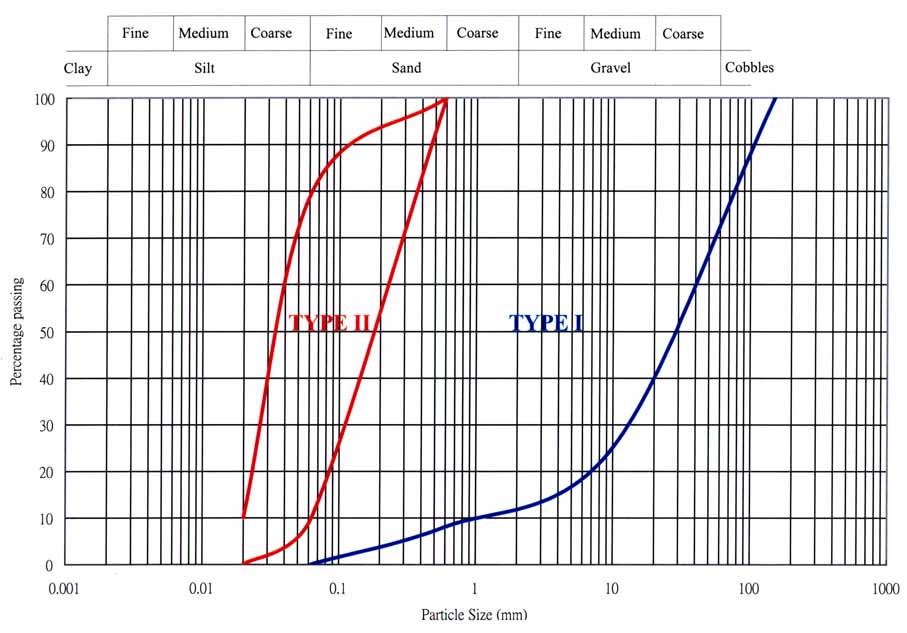
26 DRAFT GEOGUIDE 6 Construction Materials (cont d) Facings and connections: Hard or soft depending upon use and purpose including segmental block and gabion facings Fill: Natural or processed material Restrictions on electrical and chemical limits Filter and drainage materials: Conforming to Geoguide 1 (GEO, 1993) 26
27 27
28 Investigation and Testing Sampling and testing of fill materials: The source and properties of the fill may not be known at the design stage Use conservative values and undertake compliance tests on a regular basis (detailed in the Model Specification) Testing of reinforcements and connections: Number reflects the size of the structure Required to verify design assumptions: tensile test on reinforcing materials tensile test on joints and connections reinforcement pull out direct shear, fill-to-reinforcement, facing-unit-to-reinforcement, facing-unit-to-facing-unit 28
29 Design Situations Function and design life Construction conditions Loading conditions Environmental conditions Ground conditions Consequence of failure GEOGUIDE 6 Selection of Reinforced Fill System Space for construction Acceptable deformation limits Aesthetics Construction and maintenance costs Maintenance Drainage Vegetation Structural elements Design Loading Dead loads Live loads Seismic loads Construction Tolerances and serviceability limits Details and procedures Protection of reinforcements Compliance testing Factor of Safety Consequence factors Material factors Load factors Design Strength Reinforcement and facing Fill and foundation materials Fill-reinforcement interaction Design Consideration for Reinforced Fill Structures and Slopes Design Stiffness Deformation moduli Poisson ratio Design Permeability Ground Fill Filter and drainage materials Design 29
30 Define wall geometry, fill properties and reinforcement GEOGUIDE 6 Initial sizing (Section 7.3) External stability check (Section 7.4) Determination of tensile forces to be resisted by individual layers of reinforcement (Section 7.5.3) Checking rupture and pullout of individual layers of reinforcement (Section 7.5.4) Wedge stability check (Section 7.5.5) Compound stability check (Section 7.6) Serviceability check (Section 7.7) Design procedure for reinforced fill structures Spacing of reinforcement (Section 7.8) Design of connections and facing (Section 7.9 and 7.10) Drainage provisions (Section 7.11) Detailing/Drawings (Section 7.17) 30
31 External stability Use limit equilibrium methods, Geotechnical Manual for Slopes (GCO, 1984) Stability of reinforced block, Geoguide 1 (GEO, 1993) Bearing pressure, Meyerhof distribution assumed; if L/H > 0.6 use trapezoidal pressure distribution Sliding resistance, based upon the weakest material fill or ground 31
32 Internal Stability Assumptions: Design tension based upon assumption of vertical loads distributed using Meyerhof pressure (or trapezoidal if L/H < 0.6) Resistance to pull out based upon uniform normal stresses and unfactored loads pore water pressures should be considered 32
33 Analytical models The design state of stress within a reinforced fill structure determines the design tensile load in the reinforcement The state of stress inside the reinforced fill block is determined by the quantity and axial stiffness of the reinforcement Axial strain > 1%: the analytical model recommended is the Tie Back Method the lateral earth pressure in the reinforced block is in the active state, k des = k a Axial strain < 1%: the Coherent Gravity Method is assumed to apply, where k des = k o reducing to k a at a depth of 6m 33
34 Design Methods for Internal Stability Analysis of Reinforced Fill Structures 34
35 Internal Stability (cont d) The design checks for: Tension in the reinforcement rupture of reinforcement pull out Wedge stability Compound stability (i.e. failure planes located within and outside the reinforced fill block) sliding on planes between the reinforcement sliding along the reinforcement 35
36 Design of Connections Designed for maximun tension in the reinforcement Checked for failure in tension, shear and combined shear and tension 36
37 Serviceability Considerations Identify the serviceability limits GEOGUIDE 6 Most movements take place during construction Consideration is given to: creep of polymeric reinforcement creep of fine grained fill additional loading foundation settlement deterioration of the reinforcement 37


38 Specific Structures and Details Geoguide 6 covers: DRAFT GEOGUIDE 6 Superimposed walls Segmental block walls Walls with a stepped base Back-to-back walls Bridge abutments spread footings piled integral Design detailing corner and wall joints connections to cast-in-place structures 38
39 Specific Structures and Details Geoguide 6 covers: GEOGUIDE 6 Superimposed walls Segmental block walls Walls with a stepped base Back-to-back walls Bridge abutments spread footings piled integral Design detailing corner and wall joints connections to cast-in-place structures 39
40 Special Conditions Relating to Design and Construction Control in Hong Kong Temperature: Creep test temperature is usually C Mean soil temperature in Hong Kong is 26 C 0.5m behind the face temperature can reach 35 C Design temperature of 30 C is recommended Drainage: GEOGUIDE 6 The stability of reinforced fill structures relies upon good drainage. Geoguide 6 provides examples of good drainage. Checks should be made on the adequacy and efficacy of all drainage during construction, in particular during/after periods of intense rainfall. 40

41 Typical Drainage Layouts for Reinforced Fill Structures and Slopes 41

42 Typical Drainage Layouts for Highway and River Training Applications 42
43 Special Conditions Relating to Design and Construction Control in Hong Kong Seismic events: Reinforced fill structures are tolerant of earthquakes and structures need not generally be designed for seismic loads Proprietary products: GEOGUIDE 6 Certified products can be used Proprietary products not covered by a CED certificate are not approved for use in permanent works 43
")
44 Design of Reinforced Fill Slopes Slopes defined as having face inclination > 20 C from vertical External stability Internal stability Local stability of individual reinforcing elements Stability of the yielding reinforced fill mass Assumptions: Similar to walls Uniform normal stress distribution with unfactored loads Increase in stress due to compaction considered (except for pull out check) 44
45 Design of Reinforced Fill Slopes Slopes defined as having face inclination > 20 C from vertical External stability Internal stability Local stability of individual reinforcing elements Stability of the yielding reinforced fill mass Assumptions: Similar to walls Uniform normal stress distribution with unfactored loads Increase in stress due to compaction considered (except for pull out check) 45
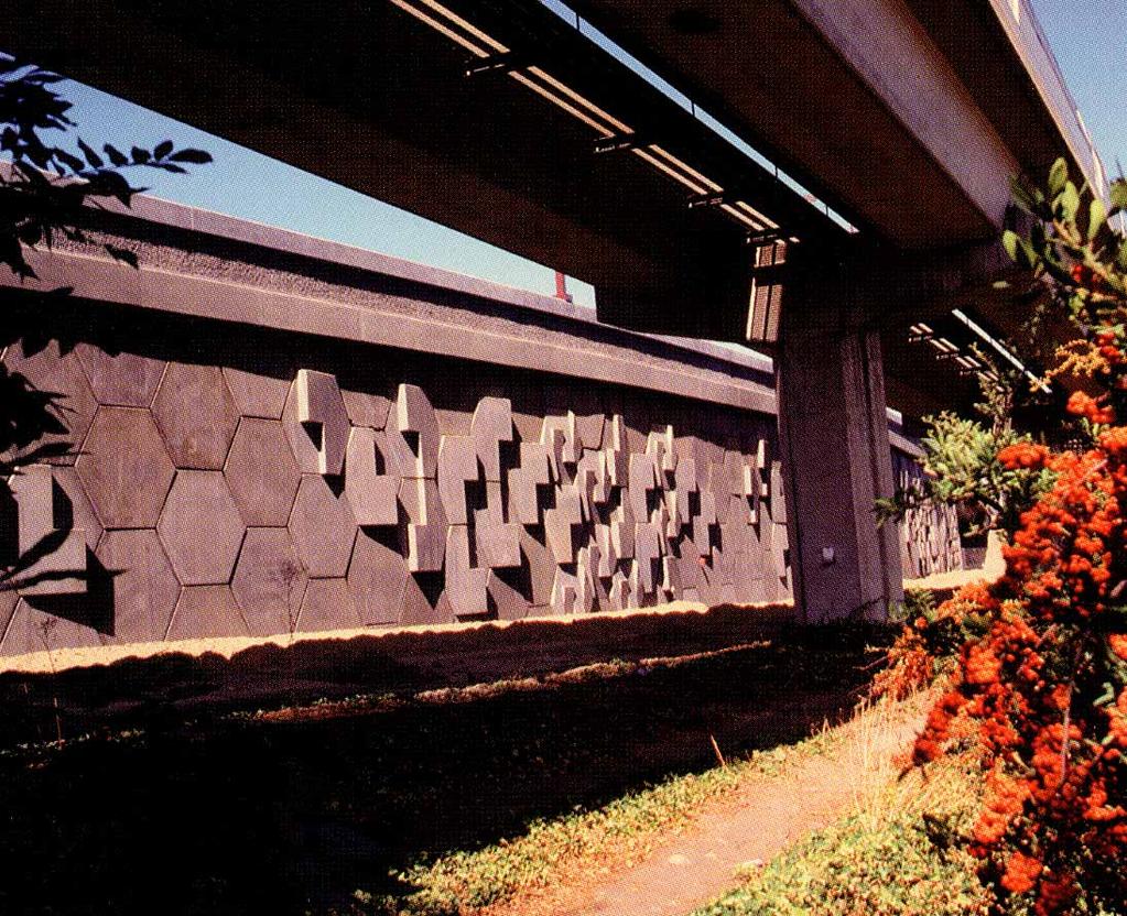
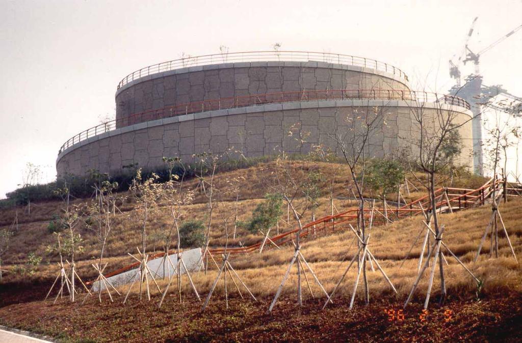
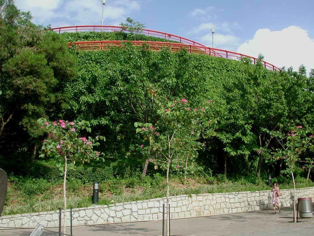
46 Aesthetics and Landscaping The aesthetics of reinforced fill is emphasised in the Geoguide Use of proven details recommended joints parapets drainage concrete finishes cracking of facing units joints between reinforced fill and cast-in-place structures Long term aesthetic appearance: leaking joints cracking and staining of facing unplanned vegetation 46
47 47
48 48
49 49
50 Procurement and Specification GEOGUIDE 6 Types of contract: Conventional Design and build Model Specification: Appendix A Suitability of contractors: Competence Patents and Client s indemnification 50
51 Construction Control Assumptions critical to the design (e.g. foundation or ground water levels) should be reviewed during construction by the designer Construction supervision: Pre-construction review Method and sequence Preparation of the foundation Temporary drainage Storage of materials Compaction Testing of materials (including tensile tests, carbon black etc.) 51
52 Comparison with Other Codes GEOGUIDE 6 BS 8006 and FHWA Walls 5m and 15m in height Extensible and inextensible reinforcement Low and high consequence of failure (i.e. γ n =1.0 or 1.1) Slopes 6m and 15m high 65 slopes 52
53 0 0 Depth (m) Geoguide 6 FHWA BS FHWA BS Design Tension (kn) Ratio of Design Tension (Other Design Guide / Geoguide 6) 14 53
54 0 0 Depth (m) Geoguide 6 FHWA BS Design Tension (kn) FHWA BS Ratio of Design Tension (Other Design Guide / Geoguide 6) 54
55 Depth (m) Geoguide 6 FHWA BS Design Tension (kn) FHWA BS Ratio of Design Tension (Other Design Guide / Geoguide 6) 55
56 Depth (m) Geoguide 6 FHWA BS FHWA BS Design Tension (kn) Ratio of Design Tension (Other Design Guide / Geoguide 6) 56
57 0 0 Depth (m) Geoguide 6 FHWA BS FHWA BS Design Tension (kn) Ratio of Design Tension (Other Design Guide / Geoguide 6) 57
58 0 0 Depth (m) Geoguide 6 FHWA BS FHWA BS Design Tension (kn) Ratio of Design Tension (Other Design Guide / Geoguide 6) 58
59 Depth (m) Geoguide 6 FHWA BS FHWA BS Design Tension (kn) Ratio of Design Tension (Other Design Guide / Geoguide 6) 59
60 Depth (m) Geoguide 6 FHWA BS FHWA BS Design Tension (kn) Ratio of Design Tension (Other Design Guide / Geoguide 6) 60
61 Geoguide Depth(m) 3 4 BS8006 Depth(m) 3 4 BS8006 Geoguide
62 62 62 GEOGUIDE 6 GEOGUIDE 6 BS8006 Geoguide 6 BS8006 Geoguide Depth(m) Depth(m)
63 63
Guide to Reinforced Fill Structure and Slope Design
 GEOGUIDE 6 Guide to Reinforced Fill Structure and Slope Design Introductory Course (Lecture 1) Geotechnical Engineering Office Civil Engineering Department The Government of the Hong Kong Special Administrative
IGS SLIDE LECTURE : VERTICAL RETAINING WALLS
 IGS SLIDE LECTURE : VERTICAL RETAINING WALLS : Lecture Notes Text Slide Basic Principles of Reinforced Soil [0] Soil is strong in compression (when confined) but weak in tension. Resistance to tensile
The Design of Reinforced Earth Walls
 The Design of Reinforced Earth Walls Jérémy PLANCQ Design Engineer, Terre Armée France Fundamental Mechanisms The Reinforced Earth is a composite material with an anisotropic artificial cohesion Layers
GEOSYNTHETICS ENGINEERING: IN THEORY AND PRACTICE
 GEOSYNTHETICS ENGINEERING: IN THEORY AND PRACTICE Prof. J. N. Mandal Department of Civil Engineering, IIT Bombay, Powai, Mumbai 400076, India. Tel.022-25767328 email: cejnm@civil.iitb.ac.in Module - 6
ENGINEERING DIRECTIVE
 Number: E-95-001 Date: 2/2/95 ENGINEERING DIRECTIVE Ross B. Dindio (Signature on Original) CHIEF ENGINEER The purpose of this engineering directive is to formally notify ALL Department engineering personnel
NPTEL Course. GROUND IMPROVEMENT Factors affecting the behaviour and performance of reinforced soil
 Lecture 27 NPTEL Course GROUND IMPROVEMENT Factors affecting the behaviour and performance of reinforced soil Prof. G L Sivakumar Babu Department of Civil Engineering Indian Institute of Science Bangalore
GEOGRIDS IN WALLS AND SLOPES. Corbet S.P 1 & Diaz M 2. AECOM Ltd Chelmsford, CM1 1HT. ( ) 2
 2") GEOGRIDS IN WALLS AND SLOPES Corbet S.P 1 & Diaz M 2 1 AECOM Ltd Chelmsford, CM1 1HT. (e-mail: steve.corbet@aecom.com ) 2 AECOM Ltd Chelmsford, CM1 1HT. (e-mail: maria.espinoza@aecom.com ) INTRODUCTION
GEOGRIDS IN WALLS AND SLOPES Corbet S.P 1 & Diaz M 2 1 AECOM Ltd Chelmsford, CM1 1HT. (e-mail: steve.corbet@aecom.com ) 2 AECOM Ltd Chelmsford, CM1 1HT. (e-mail: maria.espinoza@aecom.com ) INTRODUCTION
Design Illustrations on the Use of Soil Nails to Upgrade Loose Fill Slopes
 Design Illustrations on the Use of Soil Nails to Upgrade Loose Fill Slopes Geotechnical Engineering Office and The Hong Kong Institution of Engineers (Geotechnical Division) November 2013 2 Disclaimer
Performance of Reinforced Earth Retaining Wall with Fly Ash under Static and Dynamic Loading
 Performance of Reinforced Earth Retaining Wall with Fly Ash under Static and Dynamic Loading 1 Umesh Kumar N, 2 Padmashree M. Kalliamni 1 Geotechnical Engineer, 2 Assistant professor, 1 Civil Engineering
The design of soil nailed structures to AS4678
 The design of soil nailed structures to AS4678 Chris Bridges Technical Principal - Geotechnics chris.bridges@smec.com 7 December 2016 1 Presentation Layout Introduction Soil Nailing in AS4678 Design Process
APPENDIX B ABC STRUCTURES DESIGN GUIDE
 APPENDIX B ABC STRUCTURES DESIGN GUIDE The Cohos Evamy Partners TABLE OF CONTENTS Page No. DISCLAIMER... I 1. STRUCTURAL DESIGN GUIDELINES... 1 2. GENERAL REQUIREMENTS (FIGURE B.2, STEP 1)... 1 3. GENERAL
Available online at ScienceDirect. Procedia Engineering 91 (2014 )
") Available online at www.sciencedirect.com ScienceDirect Procedia Engineering 9 (204 ) 346 35 XXIII R-S-P seminar, Theoretical Foundation of Civil Engineering (23RSP) (TFoCE 204) Internal Stability Analyses
Available online at www.sciencedirect.com ScienceDirect Procedia Engineering 9 (204 ) 346 35 XXIII R-S-P seminar, Theoretical Foundation of Civil Engineering (23RSP) (TFoCE 204) Internal Stability Analyses
Ground Improvement Using Steel Reinforcing Strips
 SAICE Geotechnical Division: Seminar on Ground Improvement Johannesburg, South Africa 8 & 9 October, 2001 Ground Improvement Using Steel Reinforcing Strips ACS Smith Reinforced Earth (Pty) Ltd, Johannesburg,
Earth Retaining Structures and Systems Submittal Checklist. Part One: Materials and Material Properties
 Earth Retaining Structures and Systems Submittal Checklist Part One: Materials and Material Properties Provide a sample of the reinforcement material and material specifications describing the material
ICC-ES Evaluation Report Issued July 1, 2011 This report is subject to renewal in one year.
 ICC-ES Evaluation Report ESR-1959 Issued July 1, 2011 This report is subject to renewal in one year. www.icc-es.org (800) 423-6587 (562) 699-0543 A Subsidiary of the International Code Council DIVISION:
DIVISION: EXTERIOR IMPROVEMENTS SECTION: SEGMENTAL RETAINING WALLS REPORT HOLDER: ANCHOR WALL SYSTEMS EVALUATION SUBJECT:
 0 Most Widely Accepted and Trusted ICC ES Evaluation Report ICC ES 000 (800) 423 6587 (562) 699 0543 www.icc es.org ESR 1959 Reissued 07/2018 This report is subject to renewal 07/2019. DIVISION: 32 00
Design of Soil Nailed Walls According to AS
 Design of Soil Nailed Walls According to AS4678-2002 Chris Bridges, SMEC, Brisbane, Queensland Keywords: soil nail, retaining wall, Australian Standards ABSTRACT The use of soil nails in the construction
Geotechnical Analysis of Stepped Gravity Walls
 Geotechnical Analysis of Stepped Gravity Walls Baleshwar Singh 1 * and Birjukumar Mistri 2 1 Associate Professor, Civil Engineering Department, IIT Guwahati, India 2 Former Post-Graduate Student, Civil
ICBO Evaluation Service, Inc Workman Mill Road, Whittier, California
 ER-5435 Reissued May 1, 2002 ICBO Evaluation Service, Inc. 5360 Workman Mill Road, Whittier, California 90601 www.icboes.org Filing Category: DESIGN Masonry MESA RETAINING BLOCK WALL SYSTEM TENSAR EARTH
Wall Modular Block Mechanically Stabilized Earth, Item S.
 Wall Modular Block Mechanically Stabilized Earth, Item 532.0300.S. A Description (1) This special provision describes designing, furnishing materials and erecting a permanent earth retention system in
DESIGNING AND CONSTRUCTION OF T-WALL RETAINING WALL SYSTEM
 Istanbul Bridge Conference August 11-13, 2014 Istanbul, Turkey DESIGNING AND CONSTRUCTION OF T-WALL RETAINING WALL SYSTEM T. C. NEEL and K.BOZKURT ABSTRACT This work shall consist of the design, manufacture
Earth Retaining System
 Hashemite University Department of Civil Engineering Foundation Engineering Dr. Omar Al-Hattamleh Earth Retaining System Earth slopes and earth retaining structures Used to maintain two different ground
CHAPTER 11: WALLS.
 CHAPTER 11: WALLS MODULAR BLOCK WALL (DRY CAST) Rather than being pre-approved as systems, the components of Modular block walls (dry cast) are pre-approved separately. The approved MBW components are
Subject Index ASTM D , 28, 57, 63, 67, 83-86, 98, 111, ASTM D , 57
 STP952-EB/JUI. 1987 Subject Index Abrasion resistance, 120, 168-169 Apparent opening size, 7, 21, 29-30, 172-173 defined, 30 versus equivalent opening size, 9-12 Apparent slope height, 96 Approved list,
Chapter 18 EARTH RETAINING STRUCTURES
 Chapter 18 EARTH RETAINING STRUCTURES Final SCDOT GEOTECHNICAL DESIGN MANUAL June 2010 SCDOT Geotechnical Design Manual Earth Retaining Structures Table of Contents Section Page 18.1 Introduction...18-1
GEOTECHNICAL RESISTANCE FACTORS
 Chapter 9 GEOTECHNICAL RESISTANCE FACTORS Final SCDOT GEOTECHNICAL DESIGN MANUAL 9-i Table of Contents Section Page 9.1 Introduction... 9-1 9.2 Soil Properties... 9-2 9.3 Resistance Factors for LRFD Geotechnical
SPECIFICATIONS FOR PRECAST MODULAR BLOCK RETAINING WALL SYSTEM (revised 5/8/7)
") Page 1 of 7 STONE STRONG SYSTEMS SPECIFICATIONS FOR PRECAST MODULAR BLOCK RETAINING WALL SYSTEM (revised 5/8/7) PART 1: GENERAL 1.01 Description A. Work includes furnishing and installing precast modular
Page 1 of 7 STONE STRONG SYSTEMS SPECIFICATIONS FOR PRECAST MODULAR BLOCK RETAINING WALL SYSTEM (revised 5/8/7) PART 1: GENERAL 1.01 Description A. Work includes furnishing and installing precast modular
INDOT Wall System Approval Criteria and Design Review
 INDOT Wall System Approval Criteria and Design Review Yuhui Hu, P.E. Office of Geotechnical Services, INDOT March 12, 2014 Slide 1 Outline Types of earth retaining structures Types of Mechanically Stabilized
DIVISION: EXTERIOR IMPROVEMENTS SECTION: RETAINING WALLS SECTION: SEGMENTAL RETAINING WALLS REPORT HOLDER:
 0 Most Widely Accepted and Trusted ICC-ES Evaluation Report ICC-ES 000 (800) 423-6587 (562) 699-0543 www.icc-es.org ESR-1784 Issued 02/2018 This report is subject to renewal 02/2019. DIVISION: 32 00 00
5-20 FOUNDATION REPORT/GEOTECHNICAL DESIGN
 5-20 FOUNDATION REPORT/GEOTECHNICAL DESIGN REPORT CHECKLIST FOR EARTH RETAINING SYSTEMS Introduction This checklist was developed to assist the geotechnical project professionals in preparing the Foundation
Stability of a Mechanically Stabilized Earth Wall
 Stability of a Mechanically Stabilized Earth Wall GEO-SLOPE International Ltd. www.geo-slope.com 1400, 633-6th Ave SW, Calgary, AB, Canada T2P 2Y5 Main: +1 403 269 2002 Fax: +1 403 266 4851 Introduction
NPTEL Course on Ground Improvement
 NPTEL Course on Ground Improvement Prof. G. L. Sivakumar Babu (Questions) Module I - Introduction to Ground Improvement L1: Need for Ground Improvement 1. What are different types of engineering problems
NPTEL Course GROUND IMPROVEMENT USING MICROPILES
 Lecture 22 NPTEL Course GROUND IMPROVEMENT USING MICROPILES Prof. G L Sivakumar Babu Department of Civil Engineering Indian Institute of Science Bangalore 560012 Email: gls@civil.iisc.ernet.in Contents
A Review of Soil Nailing Design Approaches
 A Review of Soil Nailing Design Approaches S.N.L. Taib 1 Abstract A number of design manuals and recommendations; namely by the HA 68 [4] (U.K.), BS8006 [1] (U.K.), RDGC [7] (France) and FHWA [5] (USA)
TW1 Wall System. TENSAR technology. Tensartech Systems for Earth Retaining Walls
 Tensartech TW1 Wall System TENSAR technology Tensartech Systems for Earth Retaining Walls 2 Tensar Technology - proven practical solutions and the know-how to get them built Tensartech systems are based
INTERACTION MECHANISMS OF SOIL-GEOSYNTHETIC REINFORCEMENT
 Geotech., Const. Mat. & Env., ISSN:2186-2982(P), 2186-2990(O), Japan INTERACTION MECHANISMS OF SOIL-GEOSYNTHETIC REINFORCEMENT Mabrouk Touahmia Department of Civil Engineering, Faculty of Engineering,
UPRR INDUSTRIAL LEAD BRIDGE T-WALL RETAINING WALL SYSTEM 5.0 x 7.5 UNITS DESIGN UNIT 018 WORK PACKAGE 04
 UPRR INDUSTRIAL LEAD BRIDGE T-WALL RETAINING WALL SYSTEM 5.0 x 7.5 UNITS DESIGN UNIT 018 WORK PACKAGE 04 1. Description This work shall consist of the design, manufacture and construction of a T-WALL structure
Earthquake Design of Flexible Soil Retaining Structures
 Earthquake Design of Flexible Soil Retaining Structures J.H. Wood John Wood Consulting, Lower Hutt 207 NZSEE Conference ABSTRACT: Many soil retaining wall structures are restrained from outward sliding
Design and Construction Aids in Advanced Geosynthetics Engineering. J. N. Mandal
 Draft copy Design and Construction Aids in Advanced Geosynthetics Engineering J. N. Mandal About this book: This book is the source of current state-of-the-art knowledge and practice which he has acquired
Special Provision No. 599S22 March 2018 REQUIREMENTS FOR RETAINED SOIL SYSTEMS (RSS)
") RETAINED SOIL SYSTEM, TRUE ABUTMENT - Item No. RETAINED SOIL SYSTEM, FALSE ABUTMENT - Item No. RETAINED SOIL SYSTEM, WALL/SLOPE, HIGH PERFORMANCE - Item No. RETAINED SOIL SYSTEM, WALL/SLOPE, MEDIUM PERFORMANCE
RETAINED SOIL SYSTEM, TRUE ABUTMENT - Item No. RETAINED SOIL SYSTEM, FALSE ABUTMENT - Item No. RETAINED SOIL SYSTEM, WALL/SLOPE, HIGH PERFORMANCE - Item No. RETAINED SOIL SYSTEM, WALL/SLOPE, MEDIUM PERFORMANCE
RETAINING WALLS CHAPTER 13. Omitted parts: Section
 RETAINING WALLS CHAPTER 13 Omitted parts: Section 13.9 13.15-13.17 INTRODUCTION Retaining walls are structures that restrain soil or other materials at locations having an abrupt change in elevation. In
Chapter 2 Notation and Terminology
 Reorganized 318 Chapter Titles Chapter 1 General 1.1 Scope 1.2 Purpose 1.3 Interpretation 1.4 Drawings and Specifications 1.5 Testing and Inspection 1.6 Administatration and Enforcement 1.6.1 Retention
TensarTech TW1 WALL. earth retaining system for walls
 TensarTech TW1 WALL earth retaining system for walls Independent Assessment and Approval Tensar offers a broad variety of cost effective and attractive alternatives for all types of construction Both the
MSE WALLS CASE STUDIES. by John G. Delphia, P.E. TxDOT Bridge Division Geotechnical Branch
 MSE WALLS CASE STUDIES by John G. Delphia, P.E. TxDOT Bridge Division Geotechnical Branch COMMON RETAINING WALL TYPES CONCRETE BLOCK MSE TEMPORARY EARTH SPREAD FOOTING Gabions Drilled Shaft Soil Nail Tiedback
Best Practices for Design and Construction of MSE Walls
 Best Practices for Design and Construction Robert A. Gladstone, P.E. Executive Director Association for Mechanically Stabilized Earth Geotechnical Consultant Workshop Ohio Department of Transportation
Strata Soil Reinforcement Solutions for Slopes and Walls. Confidence runs deep with Strata.
 Strata Soil Reinforcement Solutions for Slopes and Walls Confidence runs deep with Strata. 800 000 Nature has its limits when it comes to resolving site development problems and maximizing land use. Grade
TENAX t-block retaining wall system for geogrid reinforced block walls
 TENAX t-block retaining wall system for geogrid reinforced block walls T-block system: THE solution for reinforced walls The reinforced soil technique is a construction method that is thousands of years
EFFECT OF REINFORCEMENT, BACKFILL AND SURCHARGE ON THE PERFORMANCE OF REINFORCED EARTH RETAINING WALL
 EFFECT OF REINFORCEMENT, BACKFILL AND SURCHARGE ON THE PERFORMANCE OF REINFORCED EARTH RETAINING WALL Anand M. Hulagabali 1, C. H. Solanki 1, G. R. Dodagoudar 2 and M. P. Shettar 3 1 Department of Applied
STANDARDIZATION IN GEOTECH SECTOR V.K.PATIL
 STANDARDIZATION IN GEOTECH SECTOR V.K.PATIL BOMBAY TEXTILE RESEARCH ASSOCIATION L.B.S.MARG, GHATKOPAR (W),MUMBAI-400086. WEB : btraindia.com e-mail : btra@vsnl.com What are Standards? Standards are published
 UNIT V RETAINING WALLS RETAINING WALL 2.5. Retaining walls are structures used to retain earth or water or other materials such as coal, ore, etc; where conditions do not permit the mass to assume its
Downloaded from Downloaded from /1
 PURWANCHAL UNIVERSITY VI SEMESTER FINAL EXAMINATION-2003 LEVEL : B. E. (Civil) SUBJECT: BEG359CI, Foundation Engineering. Full Marks: 80 TIME: 03:00 hrs Pass marks: 32 Candidates are required to give their
ODOT Design & Construction Requirements for MSE Walls
 ODOT Design & Construction Requirements for MSE Walls Peter Narsavage, P.E. Foundation Engineering Coordinator Ohio Department of Transportation Office of Structural Engineering 2006 Ohio Transportation
INNOVATIVE EARTH RETAINING SYSTEM ADOPTED AT THE PROPOSED PRINTING COMPLEX PROJECT FOR AITKEN SPENCE (PVT) LTD. AT MAWARAMANDIYA
 LTD. AT MAWARAMANDIYA") INNOVATIVE EARTH RETAINING SYSTEM ADOPTED AT THE PROPOSED PRINTING COMPLEX PROJECT FOR AITKEN SPENCE (PVT) LTD. AT MAWARAMANDIYA Shiromal Fernando (Email: shiromal@csec.lk) Vasana Jayasena Neomal Ferdinando
INNOVATIVE EARTH RETAINING SYSTEM ADOPTED AT THE PROPOSED PRINTING COMPLEX PROJECT FOR AITKEN SPENCE (PVT) LTD. AT MAWARAMANDIYA Shiromal Fernando (Email: shiromal@csec.lk) Vasana Jayasena Neomal Ferdinando
Application of Mechanically Stabilized Earth Wall with Geo-synthetic Strap Soil Reinforcement for False Abutment Structures
 Application of Mechanically Stabilized Earth Wall with Geo-synthetic Strap Soil Reinforcement for False Abutment Structures Fraser Mitchell, Project Coordinator, Reinforced Earth Company Daniel Calatrava
MECHANICALLY STABILIZED EARTH (MSE) WALL SYSTEMS
 WALL SYSTEMS") DRAINAGE SOLUTIONS SINCE 1908 MECHANICALLY STABILIZED EARTH (MSE) WALL SYSTEMS PERMANENT AND TEMPORARY ENGINEERED WALL SOLUTIONS ECONOMICAL DURABLE VERSATILE ARMTEC.COM MSE RETAINING WALLS Armtec Mechanically
DRAINAGE SOLUTIONS SINCE 1908 MECHANICALLY STABILIZED EARTH (MSE) WALL SYSTEMS PERMANENT AND TEMPORARY ENGINEERED WALL SOLUTIONS ECONOMICAL DURABLE VERSATILE ARMTEC.COM MSE RETAINING WALLS Armtec Mechanically
This paper describes the salient features of a
 Geogrid Reinforced Soil Walls with Welded Wire Mesh Facing to Retain the Approaches to a Flyover This paper describes the salient features of a project wherein geogrid reinforced soil walls with a welded
Access Road Construction of the Larsi Building Using Reinforced Earth Walls
 Missouri University of Science and Technology Scholars' Mine International Conference on Case Histories in Geotechnical Engineering (2013) - Seventh International Conference on Case Histories in Geotechnical
TENSARTECH TW1 WALL. earth retaining system for walls
 TENSARTECH TW1 WALL earth retaining system for walls Tensar Technology proven, practical solutions and the know-how to get them designed and built. Tensar Technology is widely adopted for Pavement Optimisation
Bureau of Materials Materials Approval Procedures
 Bureau of Materials Materials Approval Procedures MAP Number: 116-15 Effective Date: April 1, 2015 Approved By: Eileen Sheehy PROCEDURE FOR APPROVAL OF MECHANICALLY STABILIZED EARTH (MSE) RETAINING WALL
Static Response of Reinforced Soil Retaining Walls with Modular Block Facing
 Static Response of Reinforced Soil Retaining Walls with Modular Block Facing Morteza Sabet 1, Amir M. Halabian 2, Kazem Barkhordari 3 1 Graduate Student, Department of Civil Engineering, Yazd University
An information series from the national authority on concrete masonry technology. Drainage swale. (optional) Cap unit. (optional)
 Cap unit. (optional)") Provided by: Brown's Concrete Products Limited An information series from the national authority on concrete masonry technology ROLES AND RESPONSIBILITIES ON SEGMENTAL RETAINING WALL PROJECTS TEK 15-3A
Provided by: Brown's Concrete Products Limited An information series from the national authority on concrete masonry technology ROLES AND RESPONSIBILITIES ON SEGMENTAL RETAINING WALL PROJECTS TEK 15-3A
SPECIFICATION FOR REINFORCED SOIL WALL
 SPECIFICATION FOR REINFORCED SOIL WALL 1.0 EXTENT OF WORK The work shall consist of Reinforced Soil walls built in accordance with this specification and in conformity with the lines, levels and details
MagnumStone Specifications Gravity
 MagnumStone Specifications Gravity SPECIFICATION FOR MAGNUMSTONE GRAVITY MECHANICALLY STABILIZED EARTH SYSTEM PART 1: GENERAL.01Description The work consists of supplying and installing all aspects of
Geosynthetics and Reinforced Soil Structures Prof. K. Rajagopal Department of Civil Engineering Indian Institute of Technology, Madras
 Geosynthetics and Reinforced Soil Structures Prof. K. Rajagopal Department of Civil Engineering Indian Institute of Technology, Madras Lecture - 21 Geosynthetic Reinforced Soil Embankments I Good morning
Soil Nail Design: A Malaysian Perspective
 Soil Nail Design: A Malaysian Perspective Chow Chee-Meng 1 & Tan, Yean-Chin 2 1 Associate, Gue & Partners Sdn Bhd, Kuala Lumpur, Malaysia 2 Director, Gue & Partners Sdn Bhd, Kuala Lumpur, Malaysia 39-5
CONCRETE SEGMENTAL RETAINING WALLS
 32 32 23.13 CONCRETE SEGMENTAL RETAINING WALLS 1.00 GENERAL 1.01 DESCRIPTION A. The work shall consist of furnishing and installing concrete segmental retaining wall (CSRW) units to the lines, grades and
STRESS-RIBBON BRIDGES STIFFENED BY ARCHES OR CABLES
 2nd Int. PhD Symposium in Civil Engineering 1998 Budapest STRESS-RIBBON BRIDGES STIFFENED BY ARCHES OR CABLES Tomas Kulhavy Technical University of Brno, Department of Concrete and Masonry Structures Udolni
Soil Nailing: An Innovative Ground Improvement Technology
 Ground Improvement: Soil Nailing Soil Nailing: An Innovative Ground Improvement Technology Sonjoy Deb, B.Tech, Civil Associate Editor A soil-nailed system is considered as a soil-nailed retaining wall
twenty four foundations and retaining walls Foundation Structural vs. Foundation Design Structural vs. Foundation Design
 ALIED ARCHITECTURAL STRUCTURES: STRUCTURAL ANALYSIS AND SYSTEMS DR. ANNE NICHOLS SRING 2018 lecture twenty four Foundation the engineered interface between the earth and the structure it supports that
Topic: Site Formation
 Topic: Site Formation Presentation prepared by Raymond Wong February 2006 Purpose of site formation is to prepare a piece of land in order to: Accommodate building/s or other facilities which will be placed
BEHAVIOR IMPROVEMENT OF FOOTINGS ON SOFT CLAY UTILIZING GEOFOAM
 BEHAVIOR IMPROVEMENT OF FOOTINGS ON SOFT CLAY UTILIZING GEOFOAM G. E. ABDELRAHMAN AND A. F. ELRAGI Department of Civil Engineering, Fayoum University Fayoum, Egypt ABSTRACT: EPS, expanded poly-styrene
Many TensarTech TW3 Structures are in Service - A Proven Success. Design Service. earth retaining system for walls. Your local distributor is:
 Many TensarTech TW3 Structures are in Service - A Proven Success TensarTech TW3 WALL earth retaining system for walls Design Service Tensar s Civil Engineers are available to help take your project to
T-WALL.
 The T-WALL Retaining Wall System is a gravity structure constructed of individual precast T-WALL units. Each T-WALL unit consists of a front face panel and a stem, which extends back into and engages the
SPECIFICATIONS FOR PRECAST MODULAR BLOCK RETAINING WALL SYSTEM (revised 9/17/18)
") Page 1 of 8 STONE STRONG SYSTEMS SPECIFICATIONS FOR PRECAST MODULAR BLOCK RETAINING WALL SYSTEM (revised ) PART 1: GENERAL 1.01 Description A. Work includes furnishing and installing precast modular blocks
Page 1 of 8 STONE STRONG SYSTEMS SPECIFICATIONS FOR PRECAST MODULAR BLOCK RETAINING WALL SYSTEM (revised ) PART 1: GENERAL 1.01 Description A. Work includes furnishing and installing precast modular blocks
Problems and solutions. Gravity earth retaining structures
 R o a d w o r k s Problems and solutions Gravity earth retaining structures Gabion earth retaining structures Technical manuals define a retaining structure as any structure capable of resisting an applied
COLLAPSE HEIGHT OF REINFORCED EMBANKMENTS OVER NON- HOMOGENEOUS SOIL WITH OBLIQUE PULL
 IGC 2009, Guntur, INDIA COLLAPSE HEIGHT OF REINFORCED EMBANKMENTS OVER NON- HOMOGENEOUS SOIL WITH OBLIQUE PULL V.K. Chakravarthi Research Scholar, Dept. of Civil Engineering, JNTUCE, Kakinada, A.P. & Associate
Behavior of Geosynthetic-Reinforced Earth
 Behavior of Geosynthetic-Reinforced Earth Presented by Kousik Deb Assistant Professor Department of Civil Engineering IIT Kharagpur Problems for Foundations on Weak Soils Experience excessive settlement
Design of Geofoam Embankment for the. Steven F. Bartlett, Ph.D., P.E. Research Project Manager, UDOT
 Design of Geofoam Embankment for the I-15 Reconstruction Steven F. Bartlett, Ph.D., P.E. Research Project Manager, UDOT I-15 Reconstruction - Quick Facts Single Largest Highway Contract t in U.S. 17 Miles
SECTION SPECIFICATION FOR MECHANICALLY STABILIZED EARTH TWO STAGE WALL SYSTEM
 SECTION 02830 SPECIFICATION FOR MECHANICALLY STABILIZED EARTH TWO STAGE WALL SYSTEM ## THIS SECTION IS WRITTEN IN CSI 3-PART FORMAT AND IN CSI PAGE FORMAT. NOTES TO THE SPECIFIER, SUCH AS THIS, ARE INDICATED
Outline of Presentation. Behavior of Laterally Loaded Piles in A Mechanically Stabilized Earth (MSE) Wall
 Wall") Behavior of Laterally Loaded Piles in A Mechanically Stabilized Earth (MSE) Wall Jie Han, Ph.D., PE, F.ASCE Glenn L. Parker Professor of Geotechnical Engineering The University of Kansas, USA Outline of
Behavior of Laterally Loaded Piles in A Mechanically Stabilized Earth (MSE) Wall Jie Han, Ph.D., PE, F.ASCE Glenn L. Parker Professor of Geotechnical Engineering The University of Kansas, USA Outline of
STATE OF OHIO DEPARTMENT OF TRANSPORTATION SUPPLEMENTAL SPECIFICATION 863 REINFORCED SOIL SLOPES. October 19, 2012
 STATE OF OHIO DEPARTMENT OF TRANSPORTATION 863.01 Description 863.02 Materials 863.03 Construction 863.04 Method of Measurement 863.05 Basis of Payment SUPPLEMENTAL SPECIFICATION 863 REINFORCED SOIL SLOPES
TABLE OF CONTENTS. vii
 TABLE OF CONTENTS CHAPTER 1: INTRODUCTION...1 1.1 Scope...1 1.1.1 Screening...2 1.1.2 Detailed Evaluation...2 1.1.3 Retrofit Design Strategies...2 1.2 Design Earthquakes, Ground Motions, and Performance
Geo-E2010 Advanced Soil Mechanics L Wojciech Sołowski. 19 March 2017
 Geo-E2010 Advanced Soil Mechanics L Wojciech Sołowski 19 March 2017 Slope stability: review Q: Shortcomings of undrained cohesion You wrote that the shortcoming is that the analysis is short term Well
CONTENTS. Top-up Course for TCP T3 on GIFW and Building Works with Significant Geotechnical Content. Lecture 5 : Retaining Walls
 Top-up Course for TCP T3 on GIFW and Building Works with Significant Geotechnical Content Lecture 5 : Retaining Walls CONTENTS Common Types of Retaining Walls Design and Construction Considerations Supervision
SPECIFICATION FOR CORNERSTONE GEOGRID REINFORCED SEGMENTAL RETAINING WALL SYSTEM
 CornerStone Specifications Geogrid Reinforced SPECIFICATION FOR CORNERSTONE GEOGRID REINFORCED SEGMENTAL RETAINING WALL SYSTEM PART 1: GENERAL 1.01 Description The work consists of supplying and installing
BS EN :2004 EN :2004 (E)
") Contents List 1. General 1.1 Scope 1.1.1 Scope of Eurocode 2 1.1.2 Scope of Part 1-1 of Eurocode 2 1.2 Normative references 1.2.1 General reference standards 1.2.2 Other reference standards 1.3 Assumptions
Contents List 1. General 1.1 Scope 1.1.1 Scope of Eurocode 2 1.1.2 Scope of Part 1-1 of Eurocode 2 1.2 Normative references 1.2.1 General reference standards 1.2.2 Other reference standards 1.3 Assumptions
Chapter 8 Anchoring Structures
 Chapter 8 Anchoring Structures 8-1. General Structural anchors are often used to improve the stability of existing structures but, generally, should not be used as a primary means to stabilize new, large
T-WALL & STONE STRONG
 shawprecastsolutions.com & STONE STRONG Retaining Walls PRODUCT GUIDE & TECHNICAL REFERENCE MANUAL Providing the right solutions. The Retaining Wall System is a gravity structure constructed of individual
twenty six concrete construction: foundation design ELEMENTS OF ARCHITECTURAL STRUCTURES: FORM, BEHAVIOR, AND DESIGN DR. ANNE NICHOLS SPRING 2013
 ELEMENTS OF ARCHITECTURAL STRUCTURES: FORM, BEHAVIOR, AND DESIGN DR. ANNE NICHOLS SPRING 2013 lecture twenty six concrete construction: www.tamu.edu foundation design Foundations 1 Foundation the engineered
VERTI-BLOCK - DESIGN MANUAL
 Company Information General Information Verti-Block is the latest innovative forming system from Verti-Crete, LLC. Recognized worldwide for outstanding aesthetics and performance, Verti-Crete s proprietary
TENSAR RE AND RE500 GEOGRIDS FOR REINFORCED SOIL EMBANKMENTS
 Tensar International Limited Cunningham Court Shadsworth Business Park Blackburn BB1 2QX Tel: 01254 262431 Fax: 01254 266868 e-mail: info@tensar-international.com website: www.tensar-international.com
TENAX t-block retaining wall system for geogrid reinforced block walls
 TENAX t-block retaining wall system for geogrid reinforced block walls T-block system: THE solution for reinforced walls The reinforced soil technique is a construction method that is thousands of years
Figure 1: Construction of arch unit using pre-cast individual voussoir concrete blocks (Taylor et al, 2007)
") CONSTRUCTION OF TIEVENAMEENA BRIDGE USING A FLEXI-ARCH SYSTEM A.GUPTA 2, S.E.TAYLOR 1, J KIRKPATRICK 2, AE LONG 1 and I HOGG 2, 1 School of Planning, Architecture and Civil Engineering, Queen s University
CONSTRUCTION OF TIEVENAMEENA BRIDGE USING A FLEXI-ARCH SYSTEM A.GUPTA 2, S.E.TAYLOR 1, J KIRKPATRICK 2, AE LONG 1 and I HOGG 2, 1 School of Planning, Architecture and Civil Engineering, Queen s University
BEARING CAPACITY IMPROVEMENT USING MICROPILES A CASE STUDY
 BEARING CAPACITY IMPROVEMENT USING MICROPILES A CASE STUDY G.L. Sivakumar Babu 1, B. R.Srinivasa Murthy 2, D.S. N. Murthy 3, M.S. Nataraj 4 ABSTRACT Micropiles have been used effectively in many applications
Ground Improvement Prof. G. L. Sivakumar Babu Department of Civil Engineering Indian Institute of Science, Bangalore
 Ground Improvement Prof. G. L. Sivakumar Babu Department of Civil Engineering Indian Institute of Science, Bangalore Module No. # 07 Lecture No. # 22 Micropiles (Refer Slide Time: 00:30) So, we would be
Slope Stabilization with High Tensile Wire Mesh
 Slope Stabilization with High Tensile Wire Mesh Geohazards In Transportation In The Appalachian Region Conference Asheville, North Carolina Frank Amend, PE Geobrugg North America, LLC. Rocky Mount, North
Section 1: Summary and recommendations Volumes 1 3
 Section 1: Summary and recommendations Volumes 1 3 Volume 1: Seismicity, soils and the seismic design of buildings Section 2: Seismicity In this section the Royal Commission discusses the forces giving
Table of Contents 5.1 GENERAL Overview Investigation and Engineering Information
 Table of Contents Section Page 5.1 GENERAL... 5.1-1 5.1.1 Overview... 5.1-1 5.1.2 Investigation and Engineering Information... 5.1-2 5.2 PRELIMINARY GEOTECHNCIAL REPORTS... 5.2-1 5.2.1 Preliminary Geotechnical
CYPRESS Stone Geogrid Reinforced Retaining Wall Installation Specification SECTION CONCRETE SEGMENTAL RETAINING WALL PART 1 GENERAL
 CYPRESS Stone Geogrid Reinforced Retaining Wall Installation Specification SECTION 02832- CONCRETE SEGMENTAL RETAINING WALL PART 1 GENERAL 1.01 Description A) The work covered by this section includes