ENGINEERING SERVICES REPORT FOREST LAKES BOULEVARD PAVEMENT EVALUATION TAMPA ROAD TO COUNTY LINE FOR PINELLAS COUNTY, FL. May 21, 2010 URS CORPORATION
|
|
|
- Naomi Webb
- 6 years ago
- Views:
Transcription
1 ENGINEERING SERVICES REPORT FOREST LAKES BOULEVARD PAVEMENT EVALUATION TAMPA ROAD TO COUNTY LINE FOR PINELLAS COUNTY, FL May 21, 2010 URS CORPORATION
2 May 21, 2010 Mr. Brent D. Hall Senior Department Administrative Manager PINELLAS COUNTY PUBLIC WORKS 440 Court Street Clearwater, FL Re: Contract No A (DM) Professional Engineering for Environmental and Geotechnical Services Task Assignment #1 Engineering Services Report Forest Lakes Boulevard Pavement Evaluation From Tampa Road to County Line Pinellas County, FL Dear Mr. Hall: URS Corporation (URS) is pleased to submit this engineering services report summarizing the results of our site exploration and evaluation of existing pavement conditions along Forest Lakes Boulevard in Pinellas County. The work was completed in general accordance with the scope of work outlined in our revised proposal (Revision 2) dated November 6, We trust that the results of the evaluation provided in this report are satisfactory for your present needs. Please contact us if you require clarification or further discussion of any issues described herein. We appreciate the opportunity to be of service on this project and look forward to continuing to provide our services to Pinellas County on future task assignments. Sincerely, URS Corporation Frederick K. Walker, P. E. Michael R. Sharp, P. E. Vice President Senior Geotechnical Engineer
3 TABLE OF CONTENTS Page 1.0 INTRODUCTION SCOPE OF WORK EXISTING DATA REVIEW SITE RECONNAISSANCE Geotechnical Drainage SITE EXPLORATION PLAN SITE EXPLORATION RESULTS General Pavement Coring Subgrade and Embankment Soil Conditions Groundwater Conditions Dynamic Cone Penetrometer Results LABORATORY TESTING General Results DISCUSSION AND EVALUATION General Likely Pavement Failure Mechanism Contributors To Pavement Failure Recommended Surface Drainage Maintenance Activities REMEDIATION ALTERNATIVES EVALUATED General Option 1 Subgrade Excavation and Replacement Including Edgedrains Option 1A Subgrade Excavation and Replacement With No Edgedrains Option 2 Pavement Replacement - Granular Subbase w/edgedrains Option 3 Raise Existing Roadway Grade Option 4 Mill and Resurface Recommended Alternatives Long-Term Remediation Temporary Repair Recommended Maintenance LIMITATIONS OF THE REPORT PHOTOGRAPHS TABLES FIGURES APPENDICES i
4 LIST OF TABLES Table 1 Table 2 Summary of Pavement Coring Results Summary of Asphalt Pavement Core Testing Results LIST OF FIGURES Figure 1 Figure 2 Figures 3A 3E Figure 4A Figures 4B 4E Figure 5 Figure 6 Site Location Map Existing Roadway Typical Sections Subsurface Exploration Plan Soil Boring Legend Approximate Cross Sections and Subsurface Profiles Summary of Asphalt Core Gradations Conceptual Typical Section Recommended Remediation Solution LIST OF APPENDICES Appendix A Appendix B Summary of Dynamic Cone Penetrometer Results Laboratory Testing Results ii URS
5 ENGINEERING SERVICES REPORT FOREST LAKES BOULEVARD PAVEMENT EVALUATION FROM TAMPA ROAD TO COUNTY LINE PINELLAS COUNTY, FL 1.0 INTRODUCTION It is our understanding that Forest Lakes Boulevard, located in northeastern Pinellas County, was improved and extended from Tampa Road (SR 584) to just west of the Hillsborough/Pinellas county line in Since then there has been deterioration in the asphaltic concrete pavement surface course. Pinellas County has requested URS to evaluate the existing roadway in order to assess potential causes of the pavement deterioration and to provide recommendations and cost estimates for repairing the roadway. From Tampa Road to Pine Avenue, Forest Lakes Boulevard is a four-lane divided roadway. Beyond Pine Avenue, the roadway narrows to a two-lane divided roadway. The two roadways are separated by a landscaped median. Roadway lighting structures are also located in the median. The approximate location of the project is shown on Figure 1, Site Location Map. 2.0 SCOPE OF WORK To accomplish the objectives of the project, URS completed the following tasks: 1) Review of available existing documents including construction plans relating to geotechnical and roadway drainage issues, construction records, and geotechnical reports; 2) A reconnaissance of the roadway to document general pavement conditions and to note areas of particular concern and to attempt to identify drainage issues that could potentially be contributing to the pavement degradation; 3) Development of a site exploration program based on our document review and project reconnaissance; 1 URS
6 4) Completion of a limited site exploration program consisting of a series of pavement cores and auger borings to assess pavement, base, subgrade and roadway embankment materials as well as groundwater conditions; 5) Completion of a laboratory testing program on selected asphalt core and soil samples to identify asphalt types and engineering properties of the soils; 6) Evaluation and analysis of the field and laboratory data; 7) Assessment of potential causes of pavement deterioration and feasible remediation alternatives; 8) Preparation of budgetary cost estimate for recommended remediation alternative; 9) Preparation of this final report summarizing our findings, conclusions, and recommendations. 3.0 EXISTING DATA REVIEW Our initial task on the project was to complete a review of existing available data that consisted of construction plans, construction records, and geotechnical reports. The construction plans indicated a design pavement section consisting of three inches of PC-1 asphaltic concrete structural course over 10½ inches of limerock base with a minimum limerock bearing ratio (LBR) of 100. Beneath the base, the plans required 12 inches of LBR 40 Type B stabilization. The roadway section consists of curb and gutter along the inside lanes, adjacent to the median, and paved and sodded shoulders along the outside lanes. A landscaped median separates the eastbound and westbound roadways. Stormwater runoff typically drains into outside roadside swales which outfall into stormwater control ponds. Typical sections for the existing four lane and two lane portions of the roadway are provided on Figure 2. The plans also indicate that the roadway was built almost entirely on fill material ranging in thickness from about one foot to as much as about eight feet. Available construction records that were reviewed indicated that the embankment fill material, as well as the stabilized subgrade and limerock base, were generally placed and compacted as required. However, several laboratory test records on materials sampled from stockpile (pit) 2 URS
7 locations reflect American Association of State Highway and Transportation Officials (AASHTO) soil classifications of A-7-5 and A-7-6 which indicate plastic to highly plastic material. Using Florida Department of Transportation (FDOT) criteria, these materials should not be placed within four feet of the roadway base. It should be noted, however, that the available records do not identify if or where these materials were actually used. Two geotechnical reports that were prepared after construction of the roadway were also reviewed. One report by Central Florida Testing Laboratories, Inc., dated October 1, 2002, was completed as part of an evaluation of shallow soil conditions and groundwater levels in an attempt to collect data that might indicate the cause of transverse cracking taking place in certain areas of the roadway. The site exploration discussed in the report consisted of a series of seven hand auger borings, extended to a typical depth of six feet below grade, within a 300-foot section of Forest Lakes Boulevard beginning about 600 feet east of Pine Avenue. The borings were located along both sides of the roadway as well as in the median. The report indicated that the soils encountered consisted predominantly of sands and sands with small clay inclusions. Groundwater levels were encountered at depths ranging from 1.6 feet to five feet below existing grade. The report stated that the soils do not contain a sufficient amount of clay to be unsuitable from a structural standpoint however, (they) do have slower permeability rates and thus restrict the flow of surface water both vertically and horizontally. The report conclusions state that Relatively shallow water table levels found at the majority of the locations tested.may be a factor in the distress being experienced. The second geotechnical report that was reviewed by URS as part of this task was prepared by Driggers Engineering Services, Inc.. This report, dated August 4, 2004, was a Transmittal of Classification Borings and Laboratory Tests Pinellas County Roadway Beautification (Forest Lakes Blvd.). The site exploration associated with this report consisted of a series of 35 hand auger borings typically extended to a depth of five feet below existing grade. No information was provided in the report regarding the locations of the borings except that all the borings were performed within the roadway median. Geotechnical Comments included in the report indicated that the borings encountered variable thickness zones of sands, clay-sands, and clays that were apparently placed above the native soils to establish grades within the median. The comments also state that this stratigraphy would tend to perch groundwater levels above the clay soils or potentially pocket water within sand seams sandwiched within low permeability soils. The report also comments on the importance of having...the medians appropriately crowned and shaped in order to provide positive runoff and avoid ponding behind the curbing. The ponding of water behind curbs can result in eventual saturation of the adjacent pavement 3 URS
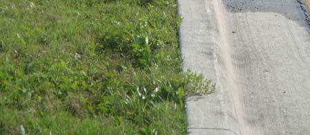
8 structure which can result in excessive pavement deformation. A review of the boring logs included in the report indicates that groundwater was typically encountered within a depth range of about three feet to five feet below grade. However, in extreme cases, the depth to groundwater was as shallow as about 2.3 feet below existing grade or was not encountered within the depth of exploration. 4.0 SITE RECONNAISSANCE 4.1 Geotechnical URS geotechnical staff visited the site on several occasions to document general pavement conditions and to note areas of particular concern for use in developing an appropriate site exploration plan. The predominantly observed pavement distress consisted of cracking with some rutting in the wheelpath areas. The pavement cracking ranged from single longitudinal cracks to severe alligator cracking with some spalling of blocks which formed potholes (Photos 1 and 2). In addition, numerous areas where the roadway has been patched were observed (Photo 3). One of our initial site visits was performed after a significant rainfall event. During this visit, numerous areas of poor drainage were observed including several areas of ponded water both against the median curb as well as along the outside roadway edge (Photos 4 and 5). In addition, as was pointed out in the Driggers Engineering Services, Inc., report, most of the roadway medians were not properly filled and shaped and were ponding water. In some areas, the ponded median water was causing seepage at the interface of the concrete gutter and the asphalt pavement (Photos 6 and 7). Additional observations by URS drainage staff are discussed below. 4.2 Drainage URS drainage staff evaluated the existing plans and visited the site to identify contributing drainage factors to the degradation of the existing pavement. Our field review of the surface drainage conditions along the project alignment was performed on March 29, A documented rainfall event of 0.97 inches occurred on March 28 and a documented rainfall event of 0.85 inches occurred on the morning of March URS
9 A visual inspection of Forest Lakes Boulevard and the associated stormwater management system resulted in the following general observations: Existing storm sewer system requires general maintenance (i.e., clearing grates, pipe desilting, etc., Photo 8); Swales directing surface runoff to ditch bottom inlets require maintenance (regular mowing) in many areas (Photo 9); Roadway maintenance/shoulder regrading is required at intersections to eliminate ponding water at turn radii. Some locations may require additional drainage structures to eliminate ponding (Photo 5); Raised medians/landscaped areas are not constructed per original design plans; median areas are depressed and hold water (Photo 6); Ponding water in shallow roadside swales is documented consistently along the entire length of roadway (Photo 10); swales are not draining to ditch bottom inlets per design even though adjacent wetlands/ponds are significantly lower than swales (Photo 11). Many of these ditches appear flat (Photo 12). In some locations the inlets are higher than the surrounding ditch holding water; Pavement is wet at medians and outer edges because of ponding water in medians and shallow roadside swales. URS design staff also reviewed the construction plans for the East-West Connector Road (Forest Lakes Boulevard), prepared by King Engineering Associates, Inc., dated 04/10/2000. One purpose of the review was to assess whether or not any of the observed pavement deterioration could be related to inadequate roadway base clearance above the seasonal high groundwater levels shown in the plans. The review considered both the existing roadway typical sections as well as the future typical sections shown in the plans. Results of this review are summarized in the table below. Stationing shown in the table was taken from the plans. 5 URS
10 Stormwater Management Facility Seasonal High Ground Water Level Elevation (ft). Low Edge of Pavement Station Profile Grade Elevation (ft). Edge of Pavement Elevation (ft) Existing Base Clearance From NWL (ft) Future Base Clearance From NWL (ft) B The review indicated that, per the as-built construction plans, the existing pavement should have a base clearance above the seasonal high groundwater levels provided in the plans that ranges from about 1.5 feet to 3.6 feet. The future widening should have a base clearance that ranges from about 1.1 feet to 3.0 feet. These clearances exceed the required one foot minimum for a facility of this type. Based on this information, the original design provided sufficient base clearance above the seasonal high groundwater levels established at the time of the design. At the time of the field observations the ponds appear to have been staging at or above the design high water (DHW) elevations of the existing ponds (Pond 4A, Photos 13 and 14; Pond 5, Photo 15). These abnormally high water elevations in the ponds relative to the present water elevations in the adjacent wetlands indicate potential blockages in the pond outfall structures and/or outfall pipes. However, the high water elevations in the ponds could also be an indication that the groundwater regime has changed since the design of the roadway and a re-evaluation of seasonal high groundwater levels may be appropriate. Recommendations for stormwater facility maintenance activities are provided in Section 8.0 of this report. 6 URS
11 5.0 SITE EXPLORATION PLAN Following the site reconnaissance, an exploration plan was developed to evaluate existing pavement, base, and subgrade conditions along the Forest Lakes Boulevard alignment. The plan included a series of asphalt cores and auger borings in areas where the pavement is exhibiting signs of distress as well as in areas where the pavement condition is relatively good. This procedure was intended to potentially identify variations in subsurface conditions that could be leading to pavement problems. Based on the existing data review and the site reconnaissance, 12 areas were identified for exploration. The table below summarizes the locations by approximate roadway centerline station and existing roadway conditions. The stationing was not identifiable in the field; therefore, the stationing shown in the table was approximated using the project plans and aerial photographs. The approximate locations of the exploration sites are shown on Figures 2A 2E, Subsurface Exploration Plan. Location No. Approximate Centerline General Pavement Condition Station Eastbound Westbound Isolated Areas of Moderate Cracking Relatively Good Moderate Cracking Minor Cracking Isolated Areas of Moderate Cracking & Patching Relatively Good Significant Cracking / Patching Significant Cracking / Spalling / Patching Relatively Good Isolated Minor Cracking Heavy Patching / Cracking / Some Spalling Moderate Cracking / Patching Isolated Areas of Minor Cracking / Patching Moderate to Significant Cracking Isolated Areas of Moderate Cracking / Patching Heavy Patching / Cracking / Some Spalling Isolated Areas of Minor Cracking / Patching Isolated Areas of Moderate Cracking / Some Spalling Moderate Cracking / Patching Minor Cracking 7 URS
12 Location No. Approximate Centerline General Pavement Condition Station Eastbound Westbound Isolated Areas of Moderate Cracking / Patching Relatively Good Minor Cracking Isolated Areas of Moderate Cracking / Patching Note: Observed cracking was primarily interconnected cracks forming small pieces ( alligator cracking) with some rutting typically located within wheelpaths. 6.0 SITE EXPLORATION RESULTS 6.1 General The site exploration was completed during the period from March 8 11, At each of the 12 locations a set of explorations was completed that consisted of one 4-inch diameter asphalt core in each of the eastbound and westbound roadways, one five-foot deep auger boring at each core location after extraction of the core, one five-foot deep auger boring within the median (where possible) and five-foot deep auger borings generally in the swale area on each side of the roadway. In addition, to assist in evaluating base and subgrade strength variations, dynamic cone penetrometer tests were performed at the auger boring locations within the roadways. Some of the pavement cores were located directly over cracked areas while others were in areas of no cracking. 6.2 Pavement Coring Results of the pavement coring are summarized in Table 1. As previously stated, the construction plans indicated a design pavement section consisting of three inches of PC-1 asphaltic concrete structural course over 10½ inches of limerock base. As shown in Table 1, the average core thickness was 2.9 inches and the average limerock base thickness was 12.2 inches. The cores indicate that the pavement section was placed in two, 1½-inch thick lifts. In roughly 50% of the cores, the two lifts of asphalt separated during extraction. Table 1 also indicates that crack depths varied from no crack to the full depth of asphalt. The overall average crack depth (considering all the cores) was 1.8 inches. 8 URS
13 6.3 Subgrade and Embankment Soil Conditions Auger borings performed after extraction of the cores and at locations previously described were advanced to a depth of approximately five feet below existing grade. Soil samples extracted from the auger borings were visually examined and classified. Representative samples of the materials were retained for subsequent laboratory testing to verify field classifications. The soils encountered in the auger borings generally consisted of a mixture of sands and clayey sands, sometimes containing lumps or balls of clay. Sandy clay was also encountered in one location and organic soils were encountered in a few borings performed in the swale areas. Figure 3A, Soil Boring Legend, provides a summary of the soil types and descriptions of the materials encountered during the site exploration. The stratigraphies encountered in each set of auger borings were plotted on the roadway cross section included in the construction plans nearest to the location of the borings set. These cross sections, with the boring stratigraphies shown, are provided in Figures 3B 3E. The strata numbers shown on the cross sections relate to the strata descriptions and soil types shown on the Soil Boring Legend (Figure 3A). The construction plans also required 12 inches of LBR 40 Type B stabilization below the limerock base. Although no clear distinction between a stabilized subgrade layer and embankment fill was evident, it appears that clay and occasionally some shell were used to provide stabilization in the material immediately below the base Groundwater Conditions In addition, to the soil stratigraphies, groundwater levels encountered at the time of the site exploration were plotted on the appropriate cross sections. To compare the groundwater levels encountered at the time of the exploration with the design seasonal high groundwater levels, the roadway drainage plans were reviewed and seasonal high groundwater levels shown on the plans closest to each of the cross sections were plotted on the cross sections. As shown in Figures 3B 3E, in most cases, the groundwater level at the time of the exploration was higher than the design seasonal high groundwater level. 9 URS
14 The data shown on the cross sections represent conditions encountered only at each boring location. Varying degrees of non-uniformity of the horizontal and vertical soil and groundwater conditions are likely to exist between boring locations Dynamic Cone Penetrometer Results Dynamic cone penetrometer (DCP) testing was performed in conjunction with the auger borings located within the roadways. This test consists of the measurement of the penetration rate of a steel cone drive point resulting from dropping a steel ring sliding weight from a specified height. Based on variations in the rate of penetration, variations in soil strength can be identified. For this project, the dynamic cone penetrometer was equipped with a 45º cone tip that was driven into the soil using a 15-pound steel weight dropped from a height of 20 inches. Tests were performed in each of the roadway auger borings at the top of the limerock base, at a depth of one foot below existing grade, and at one-foot intervals thereafter. Each test consisted of recording the number of blows required to drive the cone tip 1¾ inches. Results of the DCP testing are summarized in Appendix A. 7.0 LABORATORY TESTING 7.1 General Classification tests, including percentage finer than the U.S. #200 sieve, natural moisture content, and Atterberg limits, were performed on representative soil samples from each stratum encountered during the field investigation. Atterberg limits tests were also performed on three representative limerock base samples. Density tests were performed on two representative asphaltic concrete cores. Two composite samples, comprised of four representative cores each, were tested to evaluate the material gradation and bitumen content of the asphaltic concrete used in each of the structural course lifts. All laboratory testing was performed in general accordance with ASTM procedures. Individual results from all the testing are provided in Appendix B. 10 URS
15 7.2 Results A summary of the representative soils properties, along with AASHTO classifications and material descriptions, is presented on the Soil Boring Legend, Figure 3A. Seven identifiable soil strata were encountered during the site exploration, and based on laboratory test results, AASHTO classifications ranged from A-3, A-2-4, A-2-6, A-7-6, to A-8. Results from the limerock base tests indicated the material to be non-plastic. Gradation and bitumen content testing was performed on composite representative core samples from the top lift of the asphaltic concrete and from the bottom lift. The purpose of this testing was to confirm that the asphaltic concrete used on the project met the PC-1 requirements. Density testing was also performed. Results of the testing are shown in Table 2, Summary of Asphalt Pavement Core Testing Results. In addition, the gradation results are shown graphically in Figure 4, Summary of Asphalt Core Gradations. As can be seen in the table and figure, the material generally meets the PC-1 requirements although the composite sample from the top lift slightly exceeds the allowable percentage passing the #200 sieve and the bitumen content is slightly less than the minimum 5%. 8.0 DISCUSSION AND EVALUATION 8.1 General Based on the results of this study, it appears that the early pavement distress being experienced at Forest Lakes Boulevard is the result of several inter-related factors which primarily consist of poor surface drainage, relatively low permeability subgrade soils, and high groundwater levels. The asphaltic concrete and limerock base thickness and materials appear to be in general compliance with the project plans and specifications. As previously stated, 12 inches of LBR 40 Type B stabilization was required below the limerock base. The soil samples obtained from the auger borings within the pavement indicate that clay and occasionally some shell were used to provide stabilization in the material immediately below the base. However, the soils encountered in the auger borings sometimes contained lumps or balls of clay. FDOT specifications for stabilizing require that clay lumps be broken down or removed from the stabilized materials. 11 URS
16 It is our understanding that no specific pavement design was performed during the design phase of the Forest Lakes Boulevard project. However, based on Pinellas County Public Works Roadway Pavement Guidelines for various roadway classifications, the pavement section that was constructed (three inches of PC-1 over 10½ inches of limerock over 12 inches of stabilized subgrade) would normally be adequate for this type of roadway. 8.2 Likely Pavement Failure Mechanism The typically observed alligator cracking with some rutting in the wheelpaths is indicative of inadequate base or subgrade support. The clayey soils underlying the pavement and base should provide adequate support as long as they remain dry. However, inadequate drainage of water from the base and subgrade can lead to pavement problems as excess pore water pressures will develop under traffic loads resulting in subsequent softening of the subgrade. Although it appears that the original design provided adequate base clearance from the seasonal high groundwater levels, the soil types used as fill and as stabilizing material have relatively low permeabilities. Therefore, water infiltrating these materials as a result of inadequate surface drainage cannot be rapidly dissipated. In addition, the presence of relatively high ambient groundwater levels further diminishes the ability of the subgrade soils to drain. A comparison of the pavement conditions at the coring locations with the soil types, DCP penetration resistances, and groundwater levels encountered at each location generally indicates that areas with clayey soils (strata 3 and 4) and relatively high groundwater levels typically have lower DCP resistances in the limerock base and/or subgrade. These areas also tend to be the areas that exhibit the worst pavement conditions. 8.3 Contributors To Pavement Failure It appears that water is migrating into the pavement structure through a combination of surface infiltration, edge inflow, and from the underlying groundwater as discussed below. With respect to the underlying groundwater, as previously stated, the groundwater levels encountered during our site exploration were at or above seasonal high groundwater levels shown in the project construction plans. This could be due to the fact that the months preceding the site exploration were wetter than typical for this time of year or, in some cases, could be the result of water 12 URS
17 perched within the clayey soils. Regardless, the high groundwater could be reaching the subgrade and base material through capillary rise in these fine-grained soils. During our site reconnaissance, several instances of lack of maintenance of the existing stormwater control system were observed. This lack of maintenance could be contributing to edge inflow of water into the pavement base and subgrade. Some of the observations included ditch bottom inlet grates in need of clearing, pipes requiring desilting, roadside swales not draining to ditch bottom inlets (lack of swale in some cases), and roadway shoulders requiring maintenance/regrading to eliminate ponding water. These existing conditions allow water to pond against the roadway embankment which eventually weakens the pavement base and subgrade. Regarding surface infiltration, the most significant source of surface water infiltration appears to be the numerous cracks in the pavement surface. In addition, during our site reconnaissance, it was observed that most of the roadway medians were not properly filled and shaped and were ponding water. In several cases, the ponded median water was causing upward seepage at the interface of the concrete gutter and the asphalt pavement. This water is not only infiltrating the base and subgrade materials from below but also from above as the seepage water flows over the pavement and into existing surface cracks (Photos 6 and 7). All of these conditions will likely result in a continued cycle of deterioration of the pavement as the pavement subgrade and base weakens causing more cracking which allows more infiltration of water. To help reduce the rate of pavement deterioration, minimum recommended surface drainage maintenance activities are provided below. 8.4 Recommended Surface Drainage Maintenance Activities Based on our site reconnaissance and review of the as-built plans, the following items are recommended to help prevent surface drainage from further contributing to the pavement deterioration: Perform regular maintenance of the existing drainage system clearing debris from grates, de-silting existing pipes as needed, regular mowing, etc. 13 URS
18 Correct the grading of the roadside swales to eliminate standing water adjacent to the roadway pavement. Correct the grading of the median and landscaped areas to prevent standing water in these areas adjacent to the curb and gutter and roadway pavement. Check stormwater ponds for proper operation. 9.0 REMEDIATION ALTERNATIVES EVALUATED 9.1 General A major objective in pavement design should be to keep the base and subgrade materials from becoming saturated or exposed to constant high moisture levels. This can be accomplished by using materials that are not sensitive to the effects of moisture and by quickly removing moisture from the pavement system. Based on these considerations, we have evaluated several alternatives to provide long-term remediation as well as one option for temporary remediation which could serve as an interim solution. All of the long-term alternatives evaluated involve the removal and replacement of the existing pavement and base materials. Because Forest Lakes Boulevard is a highly-traveled roadway providing access to businesses and because maintenance of traffic may be difficult in some areas, all of the long-term options evaluated include the use of asphalt base (Type B-12.5) to reduce the time required for base construction. Another advantage of asphalt base is that the required thickness of asphalt base is less than that for a comparable limerock base which results in additional clearance between the bottom of the base and the seasonal high groundwater. In addition, in lieu of subgrade stabilization, the long-term options evaluated include the use of a relatively permeable granular subbase. The project construction plans indicate that the entire roadway will be widened to six lanes at some point in the future. The temporary remediation option consists of milling and resurfacing the existing roadway to provide a suitable riding surface until the widening can be constructed. Milling and resurfacing could also serve as an interim solution until sufficient funds are available for long-term remediation. 14 URS
19 The following sections provide discussions of the options evaluated along with our recommended alternative. All of the options discussed assume that appropriate maintenance activities will be performed to improve the existing surface drainage system. 9.2 Option 1 Subgrade Excavation and Replacement Including Edgedrains This alternative consists of removing the existing pavement and base and then excavating the existing 12-inch stabilized subgrade as well as an additional six inches of embankment material. The excavation would then be backfilled with 18 inches of AASHTO A-3 material followed by six inches of granular subbase in lieu of stabilized subgrade. The pavement section would consist of six inches of asphalt base (Type B-12.5) with two inches of Type SP asphaltic structural course and one inch of FC-9.5 friction course. This option would result in no net change in the roadway profile or grade. The replacement pavement section is based on the construction of a new section that is approximately the structural equivalent of the existing section. In addition, for two-lane and multi-lane roads with design speeds of 35 to 45 miles per hour, the FDOT Flexible Pavement Design Manual (March 2008) requires a friction course of either FC-9.5 of FC Forest Lakes Boulevard has a design speed of 45 miles per hour. The use of FC-9.5 satisfies the friction course requirement and provides one inch of structural support. Because the median includes significant landscaping as well as roadway lighting structures, excavation and replacement of the median soils is not practical. In addition, as discussed previously, there is a potential for lateral edge flow from outside the roadway. The use of relatively permeable material in the subgrade and subbase in conjunction with positive outfall to swales or drainage structures should prevent an accumulation of lateral edge flow as well as vertical infiltration from affecting the asphalt base. To provide assurance that the subgrade is being adequately drained, the design should include the use of edgedrains extending to a depth of at least two feet below the base located on each side of each roadway. Groundwater collected from the edgedrains would be piped to new or existing drainage structures for positive discharge. 15 URS
20 9.3 Option 1A Subgrade Excavation and Replacement With No Edgedrains Consideration was also given to subgrade excavation and replacement, as described above, without the use of edgedrains. However, without the edgedrains there is a potential for water to pool beneath the pavement in some low areas which could lead to early pavement deterioration. To overcome this potential for water to collect in the subgrade, daylighting of the permeable replacement subgrade material to the adjacent roadway swales would be required. However, throughout much of the roadway length, the swales are relatively shallow and adequate daylighting may not be possible. In addition, this option would require significantly more excavation and replacement of subgrade/embankment material which would exceed the cost of the edgedrains. As such, this was not considered a feasible alternative. 9.4 Option 2 Pavement Replacement - Granular Subbase w/edgedrains Another option that was evaluated was the removal of the existing pavement and base and replacement with six inches of asphalt base (Type B-12.5) with two inches of Type SP asphaltic structural course and one inch of FC-9.5 friction course. The asphalt base would be underlain by six inches of granular subbase in lieu of stabilized subgrade. In addition, edgedrains would be included. The granular subbase and edgedrains should serve to remove lateral edge inflow However, without replacing the existing subgrade, positive under-pavement drainage cannot be assured. Since this option does not eliminate the cause of early pavement distress (i.e., lack of under-pavement drainage and poor subgrade support), it is not recommended. 9.5 Option 3 Raise Existing Roadway Grade Another alternative that should keep the base and subgrade materials from becoming saturated or exposed to constant high moisture levels is to raise the grade of the existing roadway. This process would consist of removing existing pavement, base, curb and gutter, and sidewalks and then raising the entire cross section by one foot with suitable material. The pavement section would then be constructed with six inches of granular subbase followed by six inches of asphalt base (Type B-12.5). The structural course would consist of two inches of Type SP asphaltic concrete and one inch of FC-9.5 friction course. Replacement of curb and gutter and sidewalks would also be required. 16 URS
21 Although this would likely be an effective solution, some issues that will require consideration include: Driveways and side road profiles will need to be modified to fit the new profile for the roadway. This could involve extending work back into subdivision entrance areas or sideroads or potentially off the right-of-way at driveways. The drainage structures will need to be adjusted accordingly for the new profile. Clearances for any signals or signs may need adjustment, if applicable. Changing the profile may potentially get the Southwest Florida Water Management District (SWFWMD) involved, which could result in more stringent water quality requirements based on rule changes since the original project was permitted. Addressing these issues in the design and construction of the roadway at a higher grade is likely to make this option cost prohibitive. 9.6 Option 4 Mill and Resurface As previously mentioned, the project construction plans indicate that the entire roadway will be widened to six lanes at some point in the future. To save money and to provide a suitable riding surface until the widening can be constructed and the entire roadway can be remediated, milling and resurfacing the existing pavement may be an appropriate alternative. If widening is not in the foreseeable future, milling and resurfacing would provide a temporary solution until sufficient funds are available for long-term remediation of the roadway. Based on the results of coring, crack depths ranged from no crack to the full depth of asphalt. Therefore, milling the entire depth of asphaltic concrete appears to be appropriate. The asphalt could be replaced with two inches of Type SP asphaltic concrete and one inch of FC-9.5 friction course. With this option, it is likely that pavement distress will again manifest itself. However, with appropriate maintenance of the surface drainage system, it may not occur as quickly or be as 17 URS
22 severe. This option is not recommended unless there is a need to postpone a long-term solution until it can be funded. 9.7 Recommended Alternatives Long-Term Remediation The results of this study indicate that the early pavement distress is primarily the result of the inability of the soils used as fill and stabilizing material to quickly dissipate water infiltrating as a result of inadequate surface drainage coupled with the presence of relatively high ambient groundwater levels. The inability of these materials to adequately drain can lead to pavement problems resulting from softening of the subgrade. Based on this conclusion, it appears that Option 1, discussed above, is the most appropriate remediation alternative to provide an effective long-term solution to the current pavement deterioration problems. Replacement of the existing stabilized subgrade and underlying six inches of embankment with relatively permeable material, along with the installation of edgedrains will allow for the quick removal of moisture from the pavement system. A conceptual typical section for this option is shown on Figure 6. A preliminary cost estimate was prepared for this option and is summarized below. Included is a preliminary cost estimate for the roadway items along with estimates of mobilization and maintenance of traffic costs. The estimated mobilization cost is assumed to be 10% of the roadway costs while the maintenance of traffic cost is estimated to be 20% of the roadway and mobilization costs. It should be noted that this cost estimate is for preliminary budgeting purposes only. Actual costs will depend on the final design of the selected remediation option. Recommended Long-Term Remediation Option - Preliminary Cost Estimate Option # Description Roadway Mobilization Maintenance of Traffic Total 12 Subgrade & 6 Embankment 1 Excavation & Replacement Including Edgedrains $4,400,000 $440,000 $968,000 $5,808, URS
23 9.7.2 Temporary Repair As previously discussed, milling and resurfacing may be appropriate to save money and to provide a suitable riding surface until the widening can be constructed and the entire roadway remediated or to provide a temporary repair until sufficient funds are available for long-term remediation of the roadway. Based on these considerations, a budgetary estimate was prepared for milling and resurfacing assuming a milling depth of three inches and replacement of the milled pavement with two inches of Type SP asphaltic concrete and one inch of FC-9.5 friction course. The estimate is summarized below. As was done previously, the estimated mobilization cost is assumed to be 10% of the roadway costs while the maintenance of traffic cost is estimated to be 20% of the roadway and mobilization costs. Temporary Repair Option - Preliminary Cost Estimate Option # Description Roadway Mobilization Maintenance of Traffic Total Mill and Resurface Existing 4 Pavement $1,280,000 $128,500 $281,600 $1,689, Recommended Maintenance To improve surface drainage conditions and to potentially reduce the rate of pavement deterioration, implementation of the surface drainage maintenance activities discussed in Section 8.4 of this report is recommended LIMITATIONS OF THE REPORT This study has been conducted in accordance with generally accepted standards in the geotechnical engineering profession. No other warranty, expressed or implied is made. 19 URS
24 PHOTOGRAPHS


25 Photo 1 Typical Alligator Cracking Photo 2 Alligator Cracking With Spalling


26 Photo 3 Area of Significant Patching Photo 4 Ponded Water Against Curb


27 Photo 5 Ponded Water Along Intersection Radius Photo 6 Typical Ponded Water in Median


28 Photo 7 Seepage From Median Ponded Water Photo 8 Typical Ditch Bottom Inlet Grate Requiring Maintenance
29 Photo 9 Roadside Swale Requiring Mowing Photo 10 Standing Water in Roadside Swale
30 Photo 11 Standing Water in Roadside Swale Appears Higher Than Adjacent Pond Photo 12 Standing Water, Swale Not Apparent
31 Photo 13 Pond 4A Appears to be Staging Above Design High Water Elevation Photo 14 Pond 4A Appears to be Staging Above DHW Elevation
32 Photo 15 Ditch Bottom Inlet Not Draining Due to Pond 5 Above DHW Elevation
33 TABLES
34 Core Location Section Location (1) Total Core Thickness (in) Top Lift Thickness (in) Summary of Pavement Coring Results Forest Lakes Boulevard Pavement Evaluation Pinellas County Bottom Lift Thickness (in) Lifts Intact Table 1 Crack Depth (in) Limerock Base Thickness (in) Comments 1B Yes D Yes B Yes D Yes B No Bottom lift fragmented during coring 3D Yes B No D Yes B Yes D No Bottom lift highly fragmented during coring 6B Yes D Yes B No D Yes B No Top lift highly fragmented during coring 8D No B No D No B Yes D Yes B No D No B Yes D No Average: (1) B - Denotes core taken in eastbound roadway D - Denotes core taken in westbound roadway
35 Table 2 Summary of Asphalt Pavement Core Testing Results Forest Lakes Boulevard Pavement Evaluation Pinellas County Sample Identification: Top Lift - Cores #2D, #3D, #9B, and #10B Allowable Range Sieve # % Passing % Passing 3/4" /2" /8" No No No No No Allowable Range Bitumen Content: 4.7% 5-9 Core Density: lbs/ft 3 Sample Identification: Bottom Lift - Cores #2D, #3D, #9B, and #10B Allowable Range Sieve # % Passing % Passing 3/4" /2" /8" No No No No No Allowable Range Bitumen Content: 5.2% 5-9 Core Density: lbs/ft 3
36 FIGURES

37
38

39


40


41


42


43
44
45
46
47
48
49 100 Summary of Asphalt Core Testing Gradation Forest Lakes Boulevard Pavement Evaluation % Passing /4" 1/2" 3/8" No. 4 No.10 No. 40 No. 80 No. 200 Sieve Size Top Lift - Cores #2D, #3D, #9B, and #10B Bottom Lift - Cores #2D, #3D, #9B, and #10B Allowable Range URS Corporation FIGURE 5
50
51 APPENDIX A SUMMARY OF DYNAMIC CONE PENETROMETER RESULTS
52 Summary of Dynamic Cone Penetrometer Results Forest Lakes Boulevard Pavement Evaluation Pinellas County Note: EB = Eastbound Roadway, WB = Westbound Roadway Boring No.: 1-B (EB) Boring No.: 1-D (WB) Depth Soil DCP Depth Soil DCP (ft) Type (blows/1.75") (ft) Type (blows/1.75") 0.3 Top of Base Top of Base LR Boring No.: 2-B (EB) Boring No.: 2-D (WB) Depth Soil DCP Depth Soil DCP (ft) Type (blows/1.75") (ft) Type (blows/1.75") 0.3 Top of Base Top of Base LR LR Boring No.: 3-B (EB) Boring No.: 3-D (WB) Depth Soil DCP Depth Soil DCP (ft) Type (blows/1.75") (ft) Type (blows/1.75") 0.3 Top of Base Top of Base LR LR Boring No.: 4-B (EB) Boring No.: 4-D (WB) Depth Soil DCP Depth Soil DCP (ft) Type (blows/1.75") (ft) Type (blows/1.75") 0.3 Top of Base Top of Base LR LR of 3
53 Summary of Dynamic Cone Penetrometer Results Forest Lakes Boulevard Pavement Evaluation Pinellas County Note: EB = Eastbound Roadway, WB = Westbound Roadway Boring No.: 5-B (EB) Boring No.: 5-D (WB) Depth Soil DCP Depth Soil DCP (ft) Type (blows/1.75") (ft) Type (blows/1.75") 0.3 Top of Base Top of Base LR LR Boring No.: 6-B (EB) Boring No.: 6-D (WB) Depth Soil DCP Depth Soil DCP (ft) Type (blows/1.75") (ft) Type (blows/1.75") 0.3 Top of Base Top of Base LR LR Boring No.: 7-B (EB) Boring No.: 7-D (WB) Depth Soil DCP Depth Soil DCP (ft) Type (blows/1.75") (ft) Type (blows/1.75") 0.3 Top of Base Top of Base LR LR Boring No.: 8-B (EB) Boring No.: 8-D (WB) Depth Soil DCP Depth Soil DCP (ft) Type (blows/1.75") (ft) Type (blows/1.75") 0.3 Top of Base Top of Base LR LR of 3
54 Summary of Dynamic Cone Penetrometer Results Forest Lakes Boulevard Pavement Evaluation Pinellas County Note: EB = Eastbound Roadway, WB = Westbound Roadway Boring No.: 9-B (EB) Boring No.: 9-D (WB) Depth Soil DCP Depth Soil DCP (ft) Type (blows/1.75") (ft) Type (blows/1.75") 0.3 Top of Base Top of Base LR LR Boring No.: 10-B (EB) Boring No.: 10-D (WB) Depth Soil DCP Depth Soil DCP (ft) Type (blows/1.75") (ft) Type (blows/1.75") 0.3 Top of Base Top of Base LR LR Boring No.: 11-B (EB) Boring No.: 11-D (WB) Depth Soil DCP Depth Soil DCP (ft) Type (blows/1.75") (ft) Type (blows/1.75") 0.3 Top of Base Top of Base LR LR Boring No.: 12-B (EB) Boring No.: 12-D (WB) Depth Soil DCP Depth Soil DCP (ft) Type (blows/1.75") (ft) Type (blows/1.75") 0.3 Top of Base Top of Base LR LR of 3
55 APPENDIX B LABORATORY TESTING RESULTS
56
57
58
59
60
61
62
August 15, 2006 (Revised) July 3, 2006 Project No A
 July 3, 2006 Project No A") August 15, 2006 (Revised) July 3, 2006 Project No. 01-05-0854-101A Mr. David Reed, P.E. Protean Design Group 100 East Pine Street, Suite 306 Orlando, Florida 32801 Preliminary Soil Survey Report Polk Parkway
August 15, 2006 (Revised) July 3, 2006 Project No. 01-05-0854-101A Mr. David Reed, P.E. Protean Design Group 100 East Pine Street, Suite 306 Orlando, Florida 32801 Preliminary Soil Survey Report Polk Parkway
2. Pavement Materials: Consist of flexible or rigid pavements, typically HMA or PCC, respectively, or a composite of the two.
 Design Manual Chapter 6 - Geotechnical 6C - Pavement Systems 6C-1 Pavement Systems A. General Information This section addresses the importance of pavement foundations and the potential for pavement problems
How to Select the Appropriate Pavement Rehabilitation Option. David Rettner, PE American Engineering Testing, Inc.
 1 How to Select the Appropriate Pavement Rehabilitation Option David Rettner, PE American Engineering Testing, Inc. 2 Pavement Rehabilitation Selection Understanding the Problem 3 Pavement Assessment Pavement
This report presents the findings of the subsurface exploration concerning the design of the taxiway rehabilitation. Description
 September 22, 2016 American Infrastructure Development, Inc. 3810 Northdale Boulevard, Suite 170 Tampa, Florida 33624 Attn: Mr. Mohsen Mohammadi, Ph.D., P.E. Senior Consultant Mob: (813) 244-6609 E-mail:
BASE CONSTRUCTION MATERIALS A Aggregate
 BASE CONSTRUCTION 2211 AGGREGATE BASE 2211.1 DESCRIPTION This work consists of placing aggregate base. 2211.2 MATERIALS A Aggregate... 3138 Provide the class of aggregate as required by the contract. 2211.3
B. Subsurface data is available from the Owner. Contractor is urged to carefully analyze the site conditions.
 SECTION 31 23 33 - TRENCHING, BACKFILLING AND COMPACTION PART 1 - GENERAL 1.1 SCOPE A. This Section specifies the requirements for excavating and backfilling for storm sewer, sanitary sewer, water distribution
SELECTIVE FLEXIBLE PAVEMENT REHABILITATION BASED ON FORENSIC INVESTIGATION AND DEFLECTION ANALYSIS: SEVENTEEN YEARS CASE STUDY IN VIRGINIA
 0 0 0 0 SELECTIVE FLEXIBLE PAVEMENT REHABILITATION BASED ON FORENSIC INVESTIGATION AND DEFLECTION ANALYSIS: SEVENTEEN YEARS CASE STUDY IN VIRGINIA Mohamed Elfino, Ph.D., P.E. * Assistant State Materials
Applied GeoScience, Inc Hammond Dr., Suite 6 Schaumburg, Illinois
 AGI Project No. 13-276 Subsurface Investigation Report For the Proposed New Retail Center 9601 South Pulaski Road Evergreen Park, Illinois Prepared for Mr. Feras Sweis FHS Design + Build LLC 2010 West
April 7, Webster Street Sub-Surface Stormwater Storage System Bid No Bid Date: 4/13/17 ADDENDUM NO 1
 PUBLIC WORKS DEPARTMENT David A. Jones, P.E., Director April 7, 2017 Webster Street Sub-Surface Stormwater Storage System Bid No. 2017-022 Bid Date: 4/13/17 ADDENDUM NO 1 Please make the following changes
Subsurface Investigation Report. Proposed New 1-Story Building 6447 Grand Avenue Gurnee, Illinois
 AGI Project No. -11 Subsurface Investigation Report For the Proposed New 1-Story Building 6447 Grand Avenue Gurnee, Illinois Prepared for Mr. Steve Panko Key Development Partners, LLC North State Street,
TABLE OF CONTENTS. Background of Existing Facility 3. Proposed Work 4
 TABLE OF CONTENTS SECTION PAGE Background of Existing Facility 3 Proposed Work 4 Objective of this Report 4 Required Data 4 Pavement Design Procedure 5 Other Data Requirements 7 Pavement Structures 8 Pavement
SECTION 3 DRAINAGE. 3-1 General. 3-2 Drainage Ordinances and Legal Requirements
 SECTION 3 DRAINAGE 3-1 General All Drainage plans for proposed development shall be prepared by a Professional Engineer registered in Virginia, except as noted below. Further, their seal and signature
Determination of Design Infiltration Rates for the Sizing of Infiltration based Green Infrastructure Facilities
 Determination of Design Infiltration Rates for the Sizing of Infiltration based Green Infrastructure Facilities 1 Introduction This document, developed by the San Francisco Public Utilities Commission
Chapter 7. Street Drainage. 7.0 Introduction. 7.1 Function of Streets in the Drainage System. 7.2 Street Classification
 7. Introduction This chapter summarizes methods to evaluate runoff conveyance in various street cross sections and curb types in the Town of Castle Rock and identifies acceptable upper limits of street
CHECKLIST FOR STREETS, INLETS, AND STORM SEWER DESIGN
 CHECKLIST FOR STREETS, INLETS, I. STREET CLASSIFICATION AND DESIGN CRITERIA A. Determine drainage classification for the roadway section using Table 7-1 or Table 7-2. B. Determine the allowable flow depth
The following sections provide the approved standard infiltration testing specifications.
 APPENDIX F.2 INFILTRATION TESTING To properly size and locate stormwater management facilities, it is necessary to characterize the soil infiltration conditions at the location of the proposed facility.
SPECIAL CONDITIONS FOR PIPE JACKING (PJ) October, 2006
 October, 2006") Michigan Department Of Transportation 3703C (11/06) 1 Materials 1.1 Pipe SPECIAL CONDITIONS FOR PIPE JACKING (PJ) October, 2006 Page 1 of 5 The type of pipe used for the pipe jacking method shall be capable
Michigan Department Of Transportation 3703C (11/06) 1 Materials 1.1 Pipe SPECIAL CONDITIONS FOR PIPE JACKING (PJ) October, 2006 Page 1 of 5 The type of pipe used for the pipe jacking method shall be capable
Ohio Department of Transportation Division of Production Management Office of Geotechnical Engineering. Geotechnical Bulletin
 Ohio Department of Transportation Division of Production Management Office of Geotechnical Engineering Geotechnical Bulletin GB 2 SPECIAL BENCHING AND SIDEHILL EMBANKMENT FILLS Geotechnical Bulletin GB2
GEOTECHNICAL ENGINEERING REPORT
 GEOTECHNICAL ENGINEERING REPORT PROJECT MINECRAFT ACCESS ROAD BOYDTON PLANK ROAD DINWIDDIE COUNTY, VIRGINIA JOB NUMBER: 37775.003 PREPARED FOR: DINWIDDIE COUNTY PO BOX 70 DINWIDDIE COUNTY, STATE 23841
Alligator Cracking. Light. Medium. High
 Alligator Cracking Description: A series of interconnecting cracks caused by fatigue failure on the asphalt concrete surface under repeated traffic loading. Causes: Loads in excess of the current pavement
Design of Rigid Pavements
 Traffic and Highway Engineering (ІІ) CVL 4324 Chapter 20 Design of Rigid Pavements Dr. Sari Abusharar Assistant Professor Civil Engineering Department Faculty of Applied Engineering and Urban Planning
Please include this addendum in your Bid proposal for the above referenced project. Questions are in black ink, and the answers are in red ink.
 JAHarchitects, LLC PROJECT NO. 393 RIVERCREST CDD 11560 RAMBLE CREEK DRIVE, RIVERVIEW FL ADDENDUM TO BID PROJECT: RIVERCREST CDD MULTI PURPOSE FIELD MAINTENANCE BUILDING & DOG PARK POOL & CABANNA JAH PROJECT
SPECIFICATIONS FOR PRECAST MODULAR BLOCK RETAINING WALL SYSTEM (revised 5/8/7)
") Page 1 of 7 STONE STRONG SYSTEMS SPECIFICATIONS FOR PRECAST MODULAR BLOCK RETAINING WALL SYSTEM (revised 5/8/7) PART 1: GENERAL 1.01 Description A. Work includes furnishing and installing precast modular
Page 1 of 7 STONE STRONG SYSTEMS SPECIFICATIONS FOR PRECAST MODULAR BLOCK RETAINING WALL SYSTEM (revised 5/8/7) PART 1: GENERAL 1.01 Description A. Work includes furnishing and installing precast modular
CHAPTER 7 PAVEMENT DESIGN. 1. Gradation (sieve and hydrometer analysis) 3. Moisture density relationships and curves
 3. Moisture density relationships and curves") CHAPTER 7 PAVEMENT DESIGN 7.0 GENERAL The purpose of this chapter is to define the requirements for design of pavement within proposed and existing roadways for new subdivision streets and secondary roads.
CHAPTER 7 PAVEMENT DESIGN 7.0 GENERAL The purpose of this chapter is to define the requirements for design of pavement within proposed and existing roadways for new subdivision streets and secondary roads.
SECTION 26 - COLD PLANE ASPHALT CONCRETE PAVEMENT TABLE OF CONTENTS
 SECTION 26 - COLD PLANE ASPHALT CONCRETE PAVEMENT TABLE OF CONTENTS Section Page 26-1 GENERAL... 26.1 26-2 PAVEMENT KEYCUTTING... 26.1 26-3 PAVEMENT PLANING... 26.2 26-4 PLANED PAVEMENT CONFORMS... 26.3
SECTION IV. PIPELINE EXCAVATION AND BACKFILL
 SECTION IV. PIPELINE EXCAVATION AND BACKFILL A. Description of Work B. Surface Types C. Backfill D. Surface Restoration A. DESCRIPTION OF WORK 1. Extent: Excavation of trenches for pipelines shall include
SECTION EXCAVATING, BACKFILLING, AND COMPACTION FOR UTILITIES
 SECTION 02221 EXCAVATING, BACKFILLING, AND COMPACTION FOR UTILITIES PART 1 GENERAL 1.01 SUMMARY A. Related Sections: 1. 02200 - Earthwork. 2. 02660 - Water Systems. 3. 02720 - Storm Drainage System. 4.
File No Supplemental November Geotechnical and Environmental Consulting Engineers
 Supplemental Information & Geotechnical Recommendations Proposed New Solar Valley Location B (East of Building No. 7) Cañada Community College 4200 Farm Hill Boulevard Submitted to: Mr. Peter Hempel Construction
APPENDIX C INLETS. The application and types of storm drainage inlets are presented in detail in this Appendix.
 Storm Drainage 13-C-1 APPENDIX C INLETS 1.0 Introduction The application and types of storm drainage inlets are presented in detail in this Appendix. 2.0 Inlet Locations Inlets are required at locations
Mr. Michael Malone CPS Energy 145 Navarro Street San Antonio, Texas Project No
 Environmental Resources Management January 13, 2017 Mr. Michael Malone 145 Navarro Street San Antonio, Texas 78205 Project No. 0352436 CityCentre Four 840 West Sam Houston Parkway North, Suite 600 Houston,
In preparation for constructing buildings on a property, the builder. Site Preparation CHAPTER
 CHAPTER 3 Site Preparation In preparation for constructing buildings on a property, the builder must consider a number of factors related to code requirements. The buildings must be located according to
Subsurface Investigation Report
 AGI Project No. 17-154 Subsurface Investigation Report For the Proposed New One-Story Building Addition 7030 West 111 th Street Worth, Illinois Prepared for T63 Development LLC 11052 Mayflow er Lane Orland
Stormwater Standards. Clackamas County Service District No. 1. Infiltration Testing Guide
 Stormwater Standards Clackamas County Service District No. 1 APPENDIX E Infiltration Testing Guide Table of Contents Appendix E - Infiltration Testing Guide... Page E.1 General... 1 E.2 Basic Method -
C. Foundation stabilization for pipe and utility structures.
 PART 1 - GENERAL 1.1 SECTION INCLUDES A. Excavating, backfilling, and compacting for utilities, including pipe, structures, and appurtenances. B. Control of water in trenches. C. Foundation stabilization
Section 25 Aggregate Subbase
 Black text from standard FAA spec Strikeout text deletions from FAA standard spec Blue text additions to FAA standard spec Red text notes to the Engineer/won t appear in spec I. DESCRIPTION A. GRANULAR
Washtenaw Community College Design & Construction Facilities Management 4800 East Huron River Drive Ann Arbor, MI
 Washtenaw Community College Design & Construction Facilities Management 4800 East Huron River Drive Ann Arbor, MI 4810-4800 GEOTECHNICAL INVESTIGATION FOR Proposed Pavement Rehabilitation Parking Lots
Municipality of Waterville Public Sidewalk Repair Policy
 Municipality of Waterville Public Sidewalk Repair Policy Purpose - The purpose of this policy is to protect the public health, safety and welfare of the citizens and inhabitants of the Municipality by
2016 LANDFILL INSPECTION REPORT CARDINAL PLANT BRILLIANT, OHIO
 2016 LANDFILL INSPECTION REPORT GERS-16-004 CARDINAL PLANT BRILLIANT, OHIO PREPARED BY GEOTECHNICAL ENGINEERING AEP SERVICE CORPORATION 1 RIVERSIDE PLAZA COLUMBUS, OHIO Cardinal Plant Landfill Inspection
PASER Manual Gravel Roads
 Pavement Surface Evaluation and Rating PASER Manual Gravel Roads RATING 5 RATING 3 RATING 1 Contents Introduction 2 Gravel road evaluation 2 Surface conditions and defects 3 Evaluation 4 Crown 4 Drainage
SUBDIVISION SECTION STREET DESIGN MANUAL
 CITY OF ANAHEIM SUBDIVISION SECTION STREET DESIGN MANUAL A. INTRODUCTION : POLICY STATEMENT B. STREET CLASSIFICATION C. STREET STANDARDS REQUIREMENTS Requirements Approval of Street Improvement Plans Widening
PERVIOUS PAVEMENT. Alternative Names: Permeable Pavement, Porous Concrete, Porous Pavers
 4.1-a PERVIOUS PAVEMENT Alternative Names: Permeable Pavement, Porous Concrete, Porous Pavers DESCRIPTION Pervious pavement is any system comprised of a load bearing surface that allows for movement of
ITEM 6 CONCRETE CURBS, GUTTERS, AND SIDEWALKS
 ITEM 6 CONCRETE CURBS, GUTTERS, AND SIDEWALKS 6.1 DESCRIPTION This work shall consist of constructing curbs, gutters, sidewalks, ramps, local depressions and driveways of the form and dimensions shown
SECTION TRENCHING & BACKFILLING
 SECTION 02225 - TRENCHING & BACKFILLING 1.0 GENERAL 1.1 Work included in this Section includes trenching and backfilling for underground pipelines and related structures only. 1.2 Reference Specifications
SECTION EXCAVATION AND BACKFILL FOR UTILITIES AND STRUCTURES
 SECTION 02215 EXCAVATION AND BACKFILL FOR UTILITIES AND STRUCTURES PART 1 - GENERAL 1.1 DESCRIPTION: This section includes materials, testing, and installation of earthwork for excavations, fills, and
Report of Geotechnical Engineering Investigation OIA SOUTH CELL LOT (W340) AID Project No. GOA16001 Orange County, Florida GEC Project No.
 AID Project No. GOA16001 Orange County, Florida GEC Project No.") Report of Geotechnical Engineering Investigation OIA SOUTH CELL LOT (W40) AID Project No. GOA16001 Orange County, Florida GEC Project No. 956G July 6, 2017 American Infrastructure Development, Inc. 7 North
Report of Geotechnical Engineering Investigation OIA SOUTH CELL LOT (W40) AID Project No. GOA16001 Orange County, Florida GEC Project No. 956G July 6, 2017 American Infrastructure Development, Inc. 7 North
SECTION STORM DRAINAGE DESIGN, GRADING, AND WATER QUALITY TECHNICAL CRITERIA TABLE OF CONTENTS PAGE 402 STORM DRAINAGE DESIGN CRITERIA 400-1
 CITY OF THORNTON Standards and Specifications Revised: October 2012 SECTION 400 - STORM DRAINAGE DESIGN, GRADING, AND WATER QUALITY TECHNICAL CRITERIA TABLE OF CONTENTS PAGE 401 GENERAL PROVISIONS 400-1
MNDOT PAVEMENT DESIGN MANUAL
 MNDOT PAVEMENT DESIGN MANUAL Chapter 9 truction and Rehabilitation Alternates MnDOT Pavement Engineer Date Contents Introduction... 1 900 Existing Pavement-Types... 2 910 Rehabilitation with HMA Overlay
CITY OF ASTORIA PUBLIC WORKS ENGINEERING DIVISION ENGINEERING DESIGN STANDARDS FOR IN-FILL DEVELOPMENT
 CITY OF ASTORIA PUBLIC WORKS ENGINEERING DIVISION ENGINEERING DESIGN STANDARDS FOR IN-FILL DEVELOPMENT Adopted by City Council: May 21, 2007 X:\General Eng\DESIGN STANDARDS\Engineering Design Standards
Section XXV Preconstruction Assessments and Damage Mitigation Procedures
 Section XXV Preconstruction Assessments and Damage Mitigation Procedures A. Introduction - In recent years, HRSD has received an increasing number of complaints from residents and locality staff regarding
PERMEABLE INTERLOCKING PAVERS
 PERMEABLE INTERLOCKING PAVERS PART 1 - GENERAL 1.01 SECTION INCLUDES A. Subgrade Preparation B. Placement of Storage Aggregate C. Placement of Filter Aggregate D. Placement of Bedding Course E. Placement
Stormwater Local Design Manual For Houston County, Georgia
 Stormwater Local Design Manual For Houston County, Georgia Adopted November 15, 2005 TABLE OF CONTENTS 1. FORWARD... 1 2. GENERAL LEVEL OF SERVICE STANDARDS... 2 2.1. DETENTION REQUIREMENTS... 2 2.1.1.
Geotechnical Engineering Report
 Geotechnical Engineering Report Pavement Subgrade Survey State Highway 125 over Hudson Creek Ottawa County, Oklahoma September 23, 21 Terracon Project No. 415121 Prepared for: Guy Engineering Services,
StormwaterWise Landscapes: Pervious Surfaces Specifications
 StormwaterWise Landscapes: Pervious Surfaces Specifications Purpose & Benefits Stormwater runoff reduction High pollutant removal Control localized drainage problems Attractive alternative for walkways
EXISTING ROADWAY CONDITION ASSESSMENT REPORT (ERCAR) SAMPLE OUTLINE
 SAMPLE OUTLINE") EXISTING ROADWAY CONDITION ASSESSMENT REPORT (ERCAR) SAMPLE OUTLINE The Existing Roadway Condition Assessment Report (ERCAR) should include the evaluation of all elements against new construction criteria.
EXISTING ROADWAY CONDITION ASSESSMENT REPORT (ERCAR) SAMPLE OUTLINE The Existing Roadway Condition Assessment Report (ERCAR) should include the evaluation of all elements against new construction criteria.
MODEL Stormwater Local Design Manual. City of Centerville
 MODEL Stormwater Local Design Manual City of Centerville Adopted December 6, 2005 TABLE OF CONTENTS 1. FORWARD... 1 2. GENERAL LEVEL OF SERVICE STANDARDS... 1 2.1. DETENTION REQUIREMENTS... 1 2.1.1. Discharge
Earth Mechanics, Inc. Geotechnical & Earthquake Engineering
 Earth Mechanics, Inc. Geotechnical & Earthquake Engineering TECHNICAL MEMORANDUM DATE: June 3, 2009 EMI PROJECT NO: 01-143 TO: COPY: FROM: SUBJECT: John Chun, P.E. / Port of Long Beach (POLB) Jorge Castillo
FOR. by The Structural Committee of The Foundation Performance Association Houston, Texas. Document # FPA-SC-04-0
 Issued for Website Publishing Foundation Performance Association Structural Committee Page 1 of 9 RECOMMENDED PRACTICE FOR GEOTECHNICAL EXPLORATIONS AND REPORTS by The Structural Committee of The Foundation
Preliminary Geotechnical Exploration Armstrong Tract Rivers Avenue and Hanahan Road North Charleston, South Carolina S&ME Project No.
 Preliminary Geotechnical Exploration Rivers Avenue and Hanahan Road S&ME Project No. 4213-16-016 Prepared for: Charleston Water System 103 Saint Phillip Street Charleston, South Carolina 29403 Prepared
CITY OF TACOMA RIGHT-OF-WAY RESTORATION POLICY. Guidance on restoration of City Rights-of-Way
 CITY OF TACOMA RIGHT-OF-WAY RESTORATION POLICY Guidance on restoration of City Rights-of-Way Public Works Department Directors Office 747 Market Street Suite 408 Tacoma, WA 98402 253-591-5525 Right-of-Way
Design Data 6. Loads and Supporting Strengths Elliptical and Arch Pipe. Values of B d
 Design Data 6 Loads and Supporting Strengths Elliptical and Arch Pipe The hydraulic and structural characteristics of elliptical and arch shapes offer advantages, under certain conditions, over the circular
Applied GeoScience, Inc Hammond Dr., Suite 6 Schaumburg, Illinois
 AGI Project No. 13-109B Subsurface Investigation Report For the Proposed Roosevelt Middle School Site Improvements 7560 Oak Avenue River Forest, Illinois Prepared for Mr. Jerry Pilipowicz Terra Engineering,
TRANSPORTATION & PUBLIC WORKS DEPARTMENT TECHNICAL STANDARDS
 Athens-Clarke County Unified Government TRANSPORTATION & PUBLIC WORKS DEPARTMENT TECHNICAL STANDARDS JULY, 2009 PREFACE The technical standards presented herein reflect the current policies and practices
DIVISION 31 EARTHWORK 2006 Edition, Published January 1, 2006; Division Revision Date: January 31, 2012
 2006 Edition, Published January 1, 2006; Division Revision Date: January 31, 2012 PART FIVE DOCUMENTS FOR SITE AND INFRASTRUCTURE 31 00 00. EARTHWORK 31 10 00. SITE CLEARING.1 STRUCTURE REMOVAL: Include
PROJECT NO A. ISSUED: February 29, 2016
 INTERPRETIVE REPORT FOR INFILTRATION SYSTEM DESIGN, PROPOSED VILLA VERONA APARTMENT COMMUNITY, ASSESSOR S PARCEL NUMBERS 311-040-015, 311-040-021, 311-040-024, 311-040-026 AND 311-040-013, LOCATED ON THE
Town of New Tecumseth Engineering Design Criteria and Standards for Subdivisions and Capital Works Projects
 2.0 ROADWAYS 2.1 Road Classification 2.1.1 Standard Drawing Classification All Road Widths and Road Allowances shall be designed in accordance with the most recent Town of New Tecumseth Standards: TNT.SD
PARKING LOT AND ROADWAY MAINTENANCE
 Village of Vernon Hills Community Development Engineering Division Phone 847-367-3704 Fax 847-367-2541 PERMIT APPLICATION PROCESS PARKING LOT AND ROADWAY MAINTENANCE Removal and replacement, concrete and
Infiltration Guidelines
 Appendix E Infiltration Guidelines As a stormwater management method, infiltration means retaining or detaining water within soils to reduce runoff. Infiltration can be a cost-effective method to manage
Scoping & Design Project Level. By Robert J. Blight Principal Engineer Pavement Management & Technology
 Scoping & Design Project Level Data Collection & Analysis By Robert J. Blight Principal Engineer Pavement Management & Technology Goals Share process Provide knowledge Identify key data Feedback Reliable
SECTION BITUMINOUS CONCRETE PAVEMENT
 SECTION 321216 BITUMINOUS CONCRETE PAVEMENT PART 1 - GENERAL 1.1 RELATED DOCUMENTS A. Drawings and general provisions of the Contract, including General and Supplementary Conditions and Division 1 Specification
SECTION PERMEABLE INTERLOCKING CONCRETE UNIT PAVEMENT
 SECTION 32 14 13 19 PERMEABLE INTERLOCKING CONCRETE UNIT PAVEMENT SECTION 32 14 13 19 PERMEABLE INTERLOCKING CONCRETE UNIT PAVEMENT PART 1 - GENERAL 1.1 SUMMARY A. Section Includes: 1. Permeable Articulating
SECTION 19 - TRENCH EXCAVATION, BEDDING AND BACKFILL TABLE OF CONTENTS
 SECTION 19 - TRENCH EXCAVATION, BEDDING AND BACKFILL TABLE OF CONTENTS Section Page 19-1 TRENCH EXCAVATION...19.1 19-1.01 Exploratory Excavation...19.1 19-1.02 Trench Width...19.1 19-1.02.A Storm Drain
Concrete Overlays. ACPA Pennsylvania Chapter. ACPA Pennsylvania Chapter. Versatile & Sustainable Solutions. Reasons to Consider a Concrete Overlay
 Overlays February 22, 2012 ACPA Pennsylvania Chapter Overlays John M. Becker, P.E. ACPA Penn Chapter February 22, 2012 One of 25 state paving associations affiliated with ACPA National Comprised of approximately
Subsurface Exploration and Foundation Analysis Proposed New Weight Room / Fieldhouse Building 429 N Highway 83 Leakey, Texas
 Subsurface Exploration and Foundation Analysis Proposed New Weight Room / Fieldhouse Building 429 N Highway 83 Leakey, Texas InTEC Project No. S161639 April 18, 2016 Leakey ISD P.O. Box 1129 Leakey, Texas
MICHIGAN DESIGN MANUAL ROAD DESIGN CHAPTER 4 INDEX DRAINAGE
 CHAPTER 4 INDEX DRAINAGE Supplement to Chapter 4 4.01 GENERAL INFORMATION 4.01.01 References 4.01.03 General Procedures 4.02 STORM SEWER DESIGN 4.02.15 Sewer Bulkheads 4.02.18 Storm Sewers Under Structures
StormTech Construction Guide
 A division of StormTech solid end caps and pre-cored end caps StormTech chambers StormTech manifolds and fittings Acceptable fill materials per Table 1 Woven and non-woven geotextiles 80-7 DC REQUIRED
CITY OF FARGO SPECIFICATIONS CONCRETE SIDEWALKS AND DRIVEWAYS
 CONCRETE SIDEWALKS AND DRIVEWAYS PART 1 DESCRIPTION OF WORK The work to be done under this section of the Specifications and the accompanying plans consists of all labor, material, and equipment necessary
Project Type: Drainage and Storm Systems
 580 Dakin Avenue Box Culvert & Utility Improvements Project $944,952 Improvements to approx. 3,000 lf of existing 4'x5' concrete box culvert; clean interior, patch surface, fill joints/cracks; install
Sandstone Curb Replacement Standards
 Sandstone Curb Replacement Standards Division of Infrastructure Management SCOPE OF CURB REPLACEMENT (Funding Dependent) Sandstone Curb Section I - Purpose: Sandstone curb may be replaced only if existing
U.S. Army Corps of Engineers Permit Application Tips
 U.S. Army Corps of Engineers Permit Application Tips MnDOT Environmental Conference Ben Orne and Sarah Wingert, USACE 4-29-2015 US Army Corps of Engineers BUILDING STRONG Outline Introduction to Corps
Typical Subsurface Profile. November 28, 2016
 November 28, 2016 RSCCD Facility Planning, District Construction and Support Services 2323 N. Broadway, Suite 112, Santa Ana, CA 92706 Attn: Re: Ms. Allison Coburn Facilities Project Manager P: (714) 480-7530
MOA Project # Golden View Drive Intersection & Safety Upgrades
 Appropriate transitions can include extending the insulation beyond the roadway improvements, reducing the insulation thickness, or angling the insulation downward. Use of a frost tolerant section, an
CHAPTER 7 - INFRASTRUCTURE INSPECTION AND ACCEPTANCE... 2
 CHAPTER 7 - INFRASTRUCTURE INSPECTION AND ACCEPTANCE... 2 7.1. GENERAL.... 2 7.1.1. Inspection Restriction Dates.... 2 7.1.2. Complete Improvements.... 2 7.1.3. Public Improvements.... 2 7.1.4. Warranty
550 Surface Treatments
 Table of Contents 550 Surface Treatments... 550-1 550.1 Introduction... 550-1 551 Crack Sealing... 550-1 551.1 Project Selection... 550-1 551.2 Design Considerations... 550-1 552 Chip Sealing... 550-2
Preliminary Geotechnical Investigation
 Preliminary Geotechnical Investigation Lakeview Boulevard Improvements Town of Ajax, Ontario Prepared For: Dionne Bacchus & Associates Consulting Engineers Ltd. GeoPro Project No.: 16-1296-01 Revised Report
A. Texas Department Transportation 2004 Standard Specifications for Construction of Highways, Streets and Bridges (TxDOT):
:") SECTION 31 32 13.16 CEMENT STABILIZATION PART 1 GENERAL 1.1 SCOPE OF WORK A. This Section pertains to the specifications for cement stabilization of sandy or silty soil and consists of pulverizing, addition
SECTION 31 32 13.16 CEMENT STABILIZATION PART 1 GENERAL 1.1 SCOPE OF WORK A. This Section pertains to the specifications for cement stabilization of sandy or silty soil and consists of pulverizing, addition
Standards for Soil Erosion and Sediment Control in New Jersey May 2012 STANDARD FOR SLOPE PROTECTION STRUCTURES. Definition
 STANDARD FOR SLOPE PROTECTION STRUCTURES Definition Structures to safely conduct surface runoff from the top of a slope to the bottom of the slope. Purpose The purpose of this practice is to convey storm
The Work under this Section consists of performing all operations necessary to complete construction of the leveling course on the prepared subbase.
 SECTION 20.22 LEVELING COURSE Article 22.1 General The Work under this Section consists of performing all operations necessary to complete construction of the leveling course on the prepared subbase. Article
Maintaining your roads with Asphalt
 Maintaining your roads with Asphalt Maintaining your roads with Asphalt Asphalt Overlays Rehabilitation of Concrete Roads Asphalt for Preventive Maintenance Asphalt Overlays Functional overlays Typically
Municipal Stormwater Ordinances Summary Table
 APPENDIX F Municipal Ordinances Summary Table Municipality Abington Bryn Athyn Borough Hatboro Borough Ordinance, SALDO Runoff equals pre post Erosion Sediment Control Water Quality Requirements Any which
16.0 Water Quality Management Criteria for Developed Land
 October 2003, Revised February 2005 Criteria for Developed Land Page 1 16.1 Introduction 16.0 Water Quality Management Criteria for Developed Land Stormwater quality control is an integral part of any
Current Standard Plates including Transmittal Letters are available on the web at:
 MINNESOTA DEPARTMENT OF TRANSPORTATION DEVELOPED BY: Design Standards ISSUED BY: Office of Project Management and Technical Support, Design Support Section TRANSMITTAL LETTER NO. (6-03) MANUAL: Standard
November 13, IP3406. Mr. Uriah Sowell Rooney Engineering 115 Inverness Drive East, Suite 300, Englewood, CO 80112
 November 13, 2015 103IP3406 Mr. Uriah Sowell Rooney Engineering 115 Inverness Drive East, Suite 300, Englewood, CO 80112 Subject: Infiltration Testing Gates Road Valve Site Sunoco Pennsylvania Pipeline
Evaluation of Premature PCC Pavement Longitudinal Cracking in Colorado
 Evaluation of Premature PCC Pavement Longitudinal Cracking in Colorado Ahmad Ardani, Shamshad Hussain, and Robert LaForce Colorado Department of Transportation 4201 East Arkansas Avenue Denver, CO 80222
PART 1 - GENERAL 1.01 General Provisions A. The Conditions of the Contract and all Sections of Division 1 are hereby made a part of this Section.
 Specification Sheet Grass Paver TECHNICAL SPECIFICATION - Grass Covered Flexible Porous Paver with 92% Void Space and Soil Conditioner/Fertilizer Mixture CSI Master Format 32 12 43 Flexible Porous Pavement
Construction Specification for Concrete Unit Pavers
 Engineering & Construction Services Division Standard Specifications for Road Works TS 3.80 September 2017 for Concrete Unit Pavers Table of Contents TS 3.80.01 SCOPE... 2 TS 3.80.02 REFERENCES... 2 TS
CHAPTER 10 PAVEMENT DESIGN AND REPORT TABLE OF CONTENTS
 CHAPTER 10 PAVEMENT DESIGN AND REPORT TABLE OF CONTENTS Section Title Page 10.1 General... 10-1 10.1.1 Existing Streets...10-1 10.1.2 AASHTO Design...10-1 10.1.3 Pavement Type...10-1 10.1.4 Treated Subgrade...10-1
PINELLAS COUNTY SURFACE WATER UTILITY ADJUSTMENTS AND MITIGATION CREDITS POLICY
 PINELLAS COUNTY SURFACE WATER UTILITY ADJUSTMENTS AND MITIGATION CREDITS POLICY Department of Public Works Division of Environmental Management Updated October 2016 This page intentionally left blank.
Boise City Public Works General Drainage Plan Review Requirements Checklist
 Boise City Public Works General Drainage Plan Review Requirements Checklist Development Name Bldg. Permit # Drainage Reviewer Site Address Initial Review Date ODI Number Designer Company Name Treated Acres
is a possibility of the existence of permafrost as a result
 111.2 CERTAIN ASPECTS OF ALASKA DISTRICT ENGINEERS EXPERIENCE IN AREAS OF MARGINAL PERMAFROST E. L. Long In nearly twenty years of engineering and construction experience in Alaska, the Alaska District
CONTINUOUSLY REINFORCED CONCRETE AND UNPAVED ROADS CONDITION SURVEY FIELD MANUAL PUBLICATION 343 APRIL 2017 PUB 343 (4-17)
") CONTINUOUSLY REINFORCED CONCRETE AND UNPAVED ROADS CONDITION SURVEY FIELD MANUAL PUBLICATION 343 APRIL 2017 PREPARED BY: BUREAU OF MAINTENANCE AND OPERATIONS ASSET MANAGEMENT DIVISION P.O. Box 3437 HARRISBURG,
CONTINUOUSLY REINFORCED CONCRETE AND UNPAVED ROADS CONDITION SURVEY FIELD MANUAL PUBLICATION 343 APRIL 2017 PREPARED BY: BUREAU OF MAINTENANCE AND OPERATIONS ASSET MANAGEMENT DIVISION P.O. Box 3437 HARRISBURG,