A (mm) B (mm) A (mm) B (mm) 6 x 6. 6 x x x ft extension. 8ft extension ft extension 3100
|
|
|
- Paula Rodgers
- 5 years ago
- Views:
Transcription
 B (mm) x 2012 ft extension 180 x 8")

1 NOMINAL SIZE A (mm) B (mm) NOMINAL SIZE A (mm) B (mm) x 2012 ft extension 180 x x x ft extension ft extension ft extension

; part lists, B-base,")
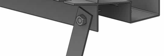
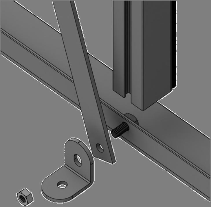
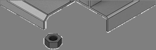
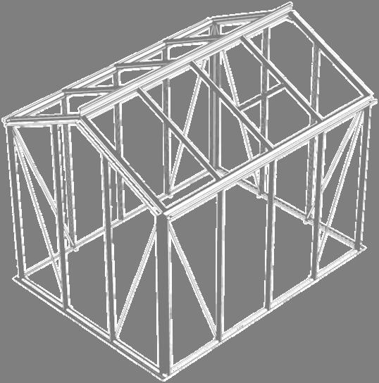
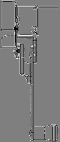
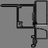
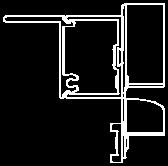
2 Thank you for purchasing your new Robinsons greenhouse. We recommend you familiarise yourself with the instructions and read all safety information before you commence assembly. This instruction manual is also available online at in our technical help section should you need to reprint it. Should you require any additional advice you can always call us on These instructions are divided into sections highlighted by a white number/letter on a black background at the bottom corner of most pages (see opposite page for details); part lists, B-base, P-preparation, 1-sides, 2-front gable, 3-rear, 4-joining the four sides together, 5-roof, -vent, 7-door, 8-glazing, 9-vent attachment, 10-door attachment, 11 anchoring down, 12 optional louvre, 13 optional shelf, 14 optional staging, 15 finishing touches. If you need to contact us for assistance please refer to the relevant section/s. If your building is longer than 12, i.e. has an extension then please also refer the separate extension manual. Safety Warning Glass and aluminium can potentially cause injury. Please ensure you wear protective goggles, gloves, headgear and suitable footwear when assembling and glazing the building. Please remember that glass is fragile and should be handled with extreme care. Always clear up and dispose of any breakages immediately. Do not assemble the greenhouse in high winds. For safety reasons and ease of assembly, we recommend that this greenhouse is assembled by a minimum of two people. Please clear all lying snow from the greenhouse roof as it can cause the roof to buckle or collapse. Site Preparation When selecting a site for your greenhouse, it is vital that you choose as flat and level an area as possible. A concrete or slabbed base will provide the most solid foundation for your greenhouse. IMPORTANT: Do not fix your building down until the building is fully assembled, including glazing. Avoid placing your greenhouse under trees or in other vulnerable locations. To minimise the risk of wind damage, try to select as sheltered a site as possible, e.g. beside a hedgerow or garden fence. Additional Considerations Please bear in mind that assembling your greenhouse can be time consuming. You may need to spread the construction over two or more days. We recommend that you avoid leaving the building partially glazed. If you ever have to leave your greenhouse half assembled and not anchored down, weigh it down with slabs or bags of sand to stop the wind moving it. You will find it helpful to prepare a large, clean and clear area in which to work in. A garage floor or flat lawn area is ideal. If you have arranged for someone to install your greenhouse for you, please check that all components are included. Some parts are numbered and can be identified by a stamped or hand written number (without the D ). Alternatively, the components can be identified by their distinctive profiles, lengths and quantities detailed in the parts list (see next page). Anchoring down your greenhouse should be the final stage of construction (including glazing). Once installed your greenhouse requires little maintenance, but to maintain the smooth running of your door(s) WD40 or similar can be applied to the door wheels and lower door guides. Guarantee Your new Robinsons greenhouse is guaranteed for 10 years against faulty manufacture of the framework. This does not include glazing, moving parts, accidental damage or wind damage. KEY SYMBOL KEY DESCRIPTION EXTERNAL VIEW INTERNAL VIEW THINK THIS SECTION RELATES TO ANOTHER (e.g. 1 to 5) CORRECT 39mm D8 DO NOT FIX DOWN! TWIST TO LOCK TIGHTEN PUSH AND HOLD CUT TO LENGTH 2
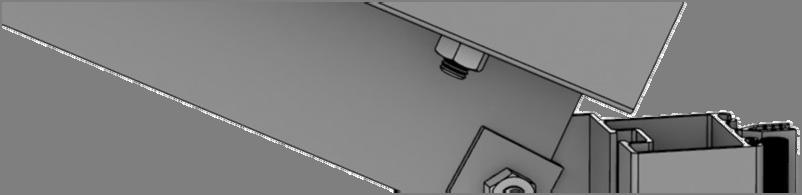
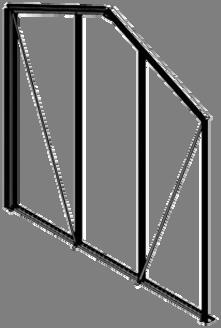
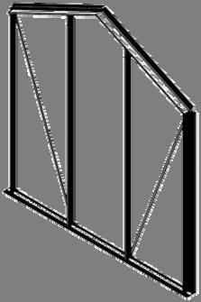
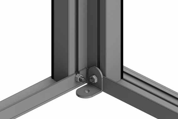
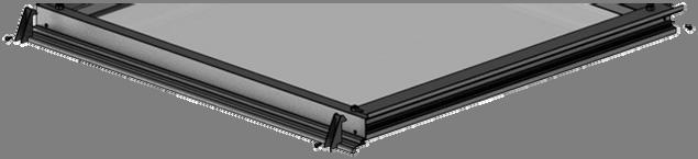
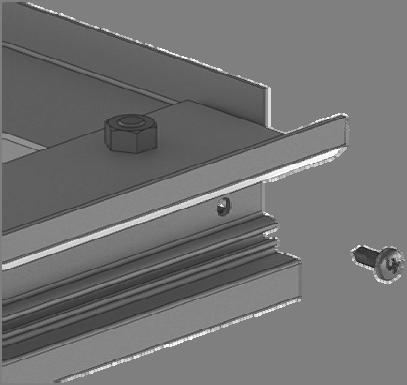
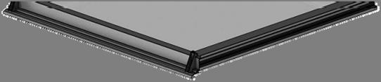
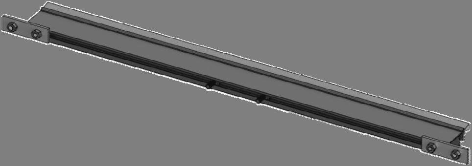
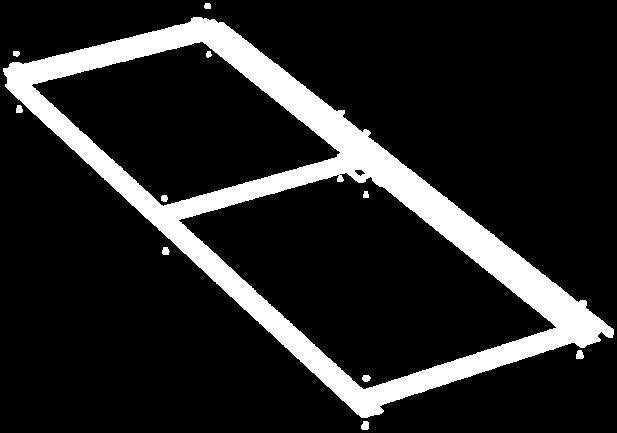
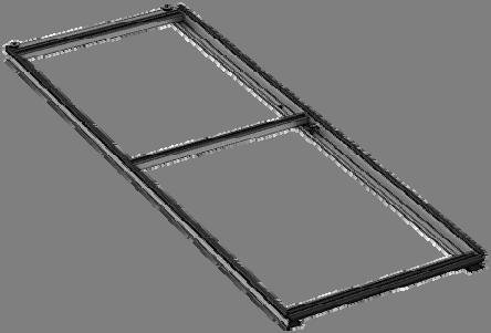
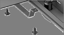
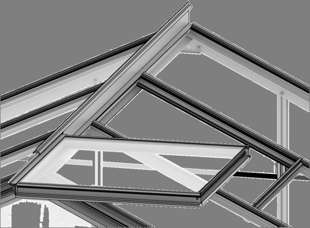
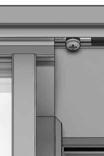
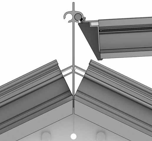
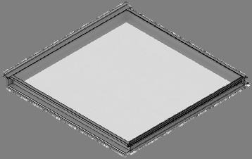
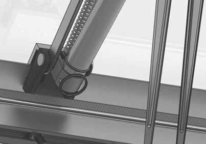
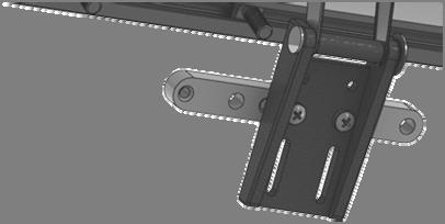
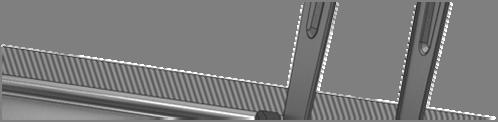
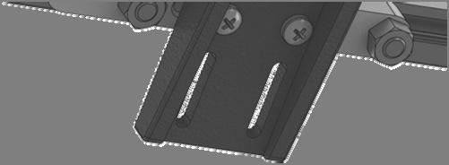
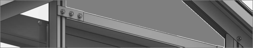
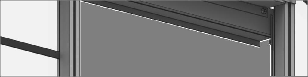
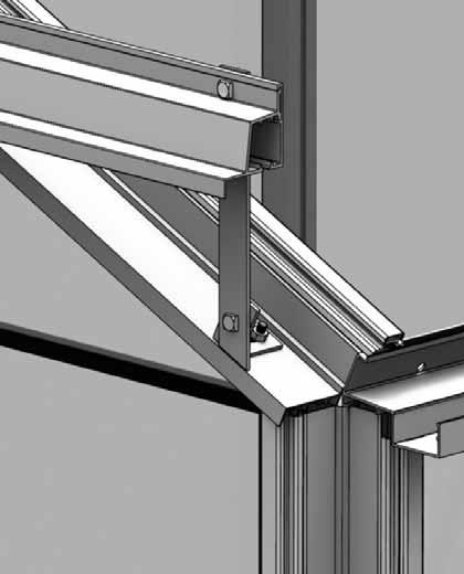
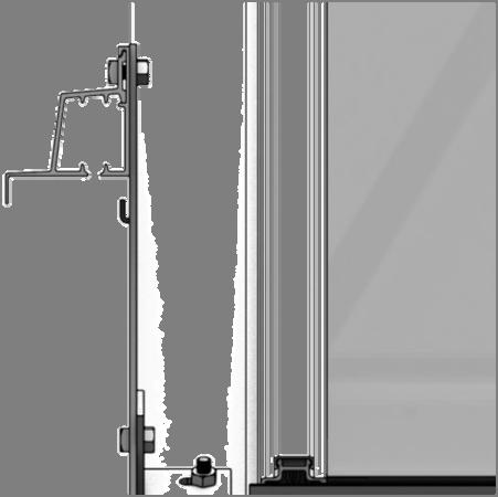
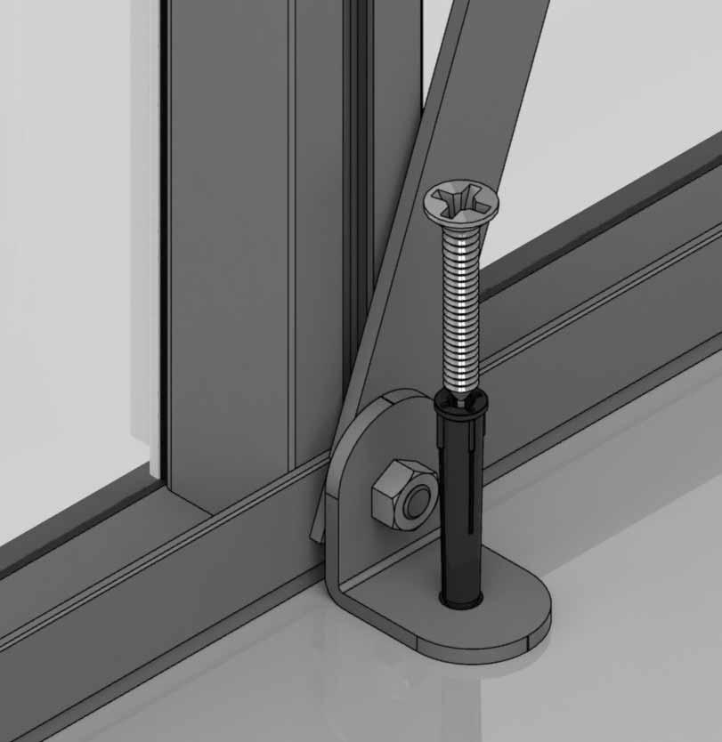
3 SECTION No B P TITLE PARTS LIST BASE PREPARATION 1 SIDES a b 7 FRONT REAR JOINING THE FOUR SIDES ROOF VENT VENT SLAM DOOR 8 GLAZING VENT ATTACHMENT DOOR ATTACHMENT ANCHORING DOWN OPTIONAL LOUVRE 13 OPTIONAL SHELVING 14 OPTIONAL STAGING 15 FINISHING TOUCHES ASSEMBLY SYNOPSIS: IMPORTANT INFORMATION / CONSIDERATIONS Most components should have a D code punched into their metal surface. Identify and separate all like for like components prior to assembly. The parts list also separates parts into the various sections shown below. Parts can also be identified by their profile pictures and stated lengths etc.. Base dimensions and recommendations. Ensure that your base is level as this will make assembly of the building, especially the glazing of the roof much more straight forward. Tools required. IMPORTANT: Use WD40 or similar in the glazing bar channels and insert the black glazing rubber prior to frame assembly. Take the side glazing bars D0 with the rubber inserted and the diagonal braces D103, use bolts to join them to the gutter and bolts to the cills (note how the head of the bolts slide into each glazing bar during construction). Again ensuring that the gable framework is rubbered-up follow the diagrams to assemble each end of the building. Make sure that you have inserted the extra bolts utilised in sections 4, 5 and 10. On the roof and side corner bars not every rubber channel will require rubber unless it is to be utilised in a partition (see separate manual and section P). Take the two sides (1) and both gables (2 & 3) and join them together on your base. It is a good idea to tie some ladders to the sides to support them if you do not have anyone to hold them for you. Attach the ridge and then the rubbered-up roof bars ensuring that they are fully butted up to the ridge and down onto the gutter. If you have cresting then it is a good idea to fit it before glazing, see section (15). Once the vent is glazed add silicone to the vent sides and top. Stand the vent/s on their hinge (vent top) and then leave the silicone to set. The slam bar D079 can be moved up and down between the roof glazing bars so that it can be butted down onto the pane of glass beneath, the autovent will be attached to it later on (9). Construct the door using the diagrams and then leave to one side ready for attachment in section (10). Layout the bar capping and covers around the building like a sundial checking that all is present and correct. You can also place the roof capping in the gutters so they are closer to hand. The glass in the sides has to bevel on the black separator strip which is on top of the 305mm high glass base panels. This bevelling action allows the glass to tuck underneath the gutter canopy. Use the capping and the self tapping screws to then hold the glass in place. The covers then enclose the screw heads giving a neat finish. A top tip is to not attach the door post capping (D814/D83) until you have fitted the door runner and threshold (10) to give you more room to manoeuvre. It is a good idea to glaze two roof sections first to ensure the building is square followed by two side sections to ensure the building isn't leaning. Take the assembled vent and slide the vent hinge D8 into the end of the ridge allowing the vent the pivot open and closed. Vent stops go either side of the vent to stop any lateral movement (so insert stop / vent / stop). Attachment of the Bayliss XL autovents. Use the bolts inserted in section (2) to attach the upper door track. The lower door runner D80 and ramp threshold D087 push down and lock together. Now that the greenhouse is finished and the door and vent/s are operating without interference then you need to anchor the building down using 2 rawl plugs and screws. Use a 7mm masonry bit in a hammer drill to create the holes. They attach to the building during the glazing process (8) like a piece of glass with a black separator above and below them. Robinsons integral cantilever staging and shelving attaches to the inside of the greenhouse frame using either square head bolts (insert four into each side glazing bar D0 during construction of the sides (1)) or rectangular crop head bolts which can be fitted retrospectively (both sets of bolts accompany the shelving/staging). This system allows the height of either the staging or the shelf to be set at an operator specific height. Commonly the staging brackets are set 900mm from the cills though you can alter this to suit the end user/s. The aluminium shelf / staging slats come in two lengths; (4 ):1240mm D2002 and ( ):180mm D2003. These slats can combine to create any length of staging required, i.e. 4 + = 10 etc... Now that the main body of the structure is complete you can add; ridge caps, downpipe fittings, eave bungs. Images showing cresting and finial attachment, this is often easiest to do after section (5) rather than using the vent apertures later on (i.e. before glazing). 3
 8 10")


 14 21 27 34")


4 Section Ref Part No. Section Size (mm) Section Ref Part No. Section Size (mm) D D D D D D D D D D D D D D RUBBER 1000 (1m) D D RUBBER 1000 (1m) D83L D174 N/A D83R D03A D D D079 PLUS FLUFF D D114 N/A D D111 N/A 2 D220 PLUS FS00 SCREW N/A D205 N/A D850L D850R 2 RUBBER 1000 (1m) D174 N/A 34 8 MAIN FRAME QUANTITIES VENTS / DOORS etc SEPERATE m
 8 10 12 D090 + D347 lock = D301 1824 1 D094 1824 1 D09 + D217 wheel = D307 11 1 D095")


5 Section Ref Part No. Section Size (mm) Section Ref Part No. Section Size (mm) D090 + D347 lock = D D D09 + D217 wheel = D D D D D D /3 D D D D D D /3 D D D D D D D D D P053 N/A 1 D D D D840B D D23 pack N/A 7 N/A 7 D D D20 pack N/A 12 D154 N/A 1 D222/B D D845 N/A 2 D842 N/A 1 5


6 THE DIMENSIONS BELOW ARE THE EXACT EXTERNAL BASE DIMENSIONS FOR THE ROBINSONS RANGE. We cannot emphasis how important it is to have a proper base for your Robinsons Greenhouse to be erected upon. It is essential that the BASE IS FLAT, LEVEL AND SQUARE AS WELL AS BEING SUBSTANTIAL enough to take the weight of the greenhouse including its 4mm glass. Give yourself enough room around your base to allow for fitting the glass and any on-going maintenance / cleaning. A slab base which is larger than the greenhouse is the ideal solution and is our preferred foundation. A brick perimeter base is equally suitable providing there is a concrete foundation beneath it. We suggest using a solid brick with no frogs or holes (quality stock bricks or semi-engineering bricks). IMPORTANT: Do not anchor your greenhouse down until it is fully assembled including glazing unless you are 100% sure your base is square and level. If not your glass will not fit properly. IMPORTANT: If you have anything overhanging the ridge on a lean-to building then please make sure it does not interfere with the motion of the roof vents. Longer building example (mm) External dimension of an 8 x 20 greenhouse. 8 x 12 main module (A) 2584 x (B) extension + (B) x 20 module (A) 2584 x (B) 352 EXTERNAL DIMENSIONS (mm) REGENT EXTENSIONS Model sizes listed are nominal, use mm measurements. i.e.: an 8 x 10 is the model 8'" x 10' 8" MODEL A (mm) WIDTH B (mm) LENGTH C (mm) DIAGONAL x x x x ft ext ft ext ft ext ft ext


 crop")


7 Feed glazing rubber into each glazing bar and trim to length. Notice that some channels are only used on a partition. Applying a lubricant to the aluminium channels will speed up insertion. The frame is assembled by feeding square headed bolts, either or in length into the slots on glazing bars and then locating those bolts through holes in purlings and cills, etc Twist in (rectangular) crop headed bolts are also used towards the end of construction to attach components to the frame when the glazing bar slots are no longer exposed at the ends. 7


8 X 2 Part No mm Quantity D D042 D X 2 D D D174 4 M- 4 M- 8 D043 M- 12 NUT Rubber X 2 Part No mm Quantity D D014 D X 2 D0 17 D D174 4 M- M- 10 D021 M- 1 NUT Rubber X 2 Part No mm Quantity D X 2 D015 D022 D D D D174 8 M- 8 M- 12 M- 20 NUT Rubber X 2 Part No mm Quantity D X 2 8 D01 D023 D D D D174 8 M- 10 M- 14 M- 24 NUT Rubber


9 D103 D0 TRANSIT BOLT ON DIAGONALS D0 D103 9


10 Part No mm Quantity D03A D D D D850L D850R Part No mm Quantity D111 1 D174 4 D227 17m MX10 10 MX15 12 MNUT 22 D850R D850L + D051 D051 D103 D103 D048 D048 D03A 10


11 D850L D850R D850L D111 D051 D850L D048 D103 D051 D103 D048 D051 D174 D03A D03A 11


12 Part No mm Quantity D03A D D D D850L D850R Part No mm Quantity D111 1 D174 4 D227 17m MX10 8 MX15 10 MNUT 18 D850R D850L D051 D051 D103 D103 D048 D048 D03A 12


13 D850L D850R D111 D850L D051 D850L D048 D103 D103 D048 D051 D174 D03A D03A 13


14 14 EQUAL


15 Part No mm Quantity D D RUBBER Part No mm Quantity Part No mm Quantity Part No mm Quantity D D D D D D RUBBER RUBBER RUBBER D03 2 D03 D03 D0 15


16 Part No mm Quantity D Part No D220 PLUS FS00 SCREW mm Quantity N/A 2 D83L 13 1 D205 N/A 2 D of - 10 x 10 pane D83R 13 1 D SY- BOLMX SYNUTM M 4 8 X 12 S/T FS017 8 x 19 S/T FS D83R 2 D83R D8 D83L D8 D of - 10 x 10 pane 1


17 2 2 D82 D83L D82 2 FLIP VIEW 2 2 CUT mm SILICONE D119 17
18 Part No SY- BOLMX11 SY- BOLMX15 SYBOLM X11CROP mm Quantity SYNUTM N/A 4 Part No mm Quantity D079 PLUS FLUFF D114 N/A 2 D114 D079 D114 FLIP VIEW 18


19 D893 GLASS D1210 GLASS D893 GLASS 19


20 D x 812 pane Part No mm Q Part No mm Q D090 + D347 lock = D D D D P053 N/A 1 D x 922 pane D09 + D217 wheel = D D D D D840B 4000 D23 PACK. 1 N/A 7 N/A 7 D20 PACK N/A 12 4 D095 D301 D095 D094 A D233 A D233 B B B D232 33mm D232 20


21 D x 812 pane C D x 922 pane D232 D x 922 pane C E E D307 8 D097 D225 F D225 F 7 H D840B 7 D840B G D840B P053 H 21 G
 D837")


22 PART No Section Size (mm) D837 D817 D837 D817 D D D D D D D D D812 S D82 D813 D83 D814 D83 D814 D82 D813 D D D825 D D D D B D809 D809 D809 D809 D809 D879 D878 D878 D878 D879 D825 D825 D825 D825 D825 D834 D812 D812 D812 D834 D82 D828 D828 D82 D813 D81 D81 D813 22

 8 10 12 D120 S 10")


23 X Y X R R A U R C S S S S S S B D B B B B B X Z X PART No Size (mm) D120 S 10 X S S S M D893 R 10 X D1210 U 10 X D1208 A 10 X D1254 B 10 X D911 C 555 X L D912 D 555 X D900 X ANGLE 4 B D90 D729 B B M 10 X 72 1 L 525X 100 B D1228 Y APEX 1 D903 Z APEX 1 D222/B 590 long 1 D101 / ROSEPS 10 long D101 / ROSEPS 10 long 1 45 Y Z 30 X


24 D220 D220 24


25 D82 D079 25


26 Part No mm Q D Part No mm Q D D D154 1 D D D845 2 SY- 10 BOLMX15 SYNUTM 10 D845 D D83 N/A 1 D814 D154 D13 D845 D051 2


27 15 3 N/A 3 D084 D083 D N/A 4 D N/A 2 D153 27


28 Part No Q D80 1 D087 1 D087 D80 D80 D087 D204R Part No D312 D204L /B D204R /B Q D312 D153 D154 28


29 Part No Q D842 1 D112 1 SYBOLM X11CROP 3 D112 29


30 O7mm 30


")


31 Part No mm Quantity D18L D18R (handle) D D FS D1 D1 D18L D18R D15 D15 INTERNAL VIEW D729TG x 525 panes x PINCH ALL GLASS RETAINERS BEFORE GLAZING 31 D15


32 Example: 2x 4 3 slat shelves ST0304 = 8 run crop D2013 D0 D048 D048 D2014 crop D2002 =1240mm D2002 =1240mm D2014 D D2003 =180mm


33 Example: 2x 4 7 slat staging ST0704 = 8 run D048 D0 D2045 D2043 D048 D2044 crop crop D204 D204 D2047 D2044 D2045 D2043 D2042 D2042 D2042 D2002 =1240mm FINISH D2002 =1240mm START D2003 =180mm D2002 =1240mm 33


34 D214 D203 SILICONE SILICONE D119 D201 D119 CUT D208 D048 D202 D211 D841 SILICONE D119 D048 D211 D207 D048 D20 34


35 End finials need to be pinched onto ridge using DV282 grub screws. Depending on your ridge length a half cresting may need to be cut or/ and some spacer bar DV281 cut into two equal sections. Each finial and cresting piece needs to be siliconed D119 into place. CUT mm SILICONE D119 DV282 ROCREALU DV281 ROFINALU DV281 EQUAL 35
36 Please be aware that this is a multi-national manual, if you spot any errors or have any constructive comments regarding the manual please james.spooner@greenhousepeople.co.uk and I will make the necessary amendments. Whilst the information contained in this booklet is accurate at the time of publication, changes in the course of Robinsons policy of improvement through development and design might not be indicated. We point out this fact to avoid any infringements of the Trade Descriptions Act and also to advise that Robinsons Greenhouses reserve the right to change specifications and materials without prior notice. In addition any photographs of completed buildings would be most appreciated to add to our portfolio. THIS GREENHOUSE BOX WAS PACKED BY: DATE: To contact Robinsons Customer Services us at sales@robinsonsgreenhouses.co.uk or call us on Our address is Robinsons Greenhouses, Unit 19 Blythe Park, Cresswell, Stoke-on-Trent, Staffordshire, ST11 9RD 3
A (mm) B (mm) A (mm) B (mm) 10 x x x x ft extension. 8ft extension ft extension 3100
 B (mm) A (mm) B (mm) 10 x x x x ft extension. 8ft extension ft extension 3100") NOMINAL SIZE A (mm) B (mm) NOMINAL SIZE A (mm) B (mm) x 6 2012 6ft extension 1860 x 8 2632 3208 x 3252 x 12 3872 8ft extension 2480 ft extension 30 12ft extension 3720 - Thank you for purchasing your new
NOMINAL SIZE A (mm) B (mm) NOMINAL SIZE A (mm) B (mm) x 6 2012 6ft extension 1860 x 8 2632 3208 x 3252 x 12 3872 8ft extension 2480 ft extension 30 12ft extension 3720 - Thank you for purchasing your new
A (mm) B (mm) A (mm) B (mm) 5lt X lt x lt x 8. 5lt x ft extension. 8ft extension ft extension 3100
 B (mm) A (mm) B (mm) 5lt X lt x lt x 8. 5lt x ft extension. 8ft extension ft extension 3100") NOMINAL SIZE A (mm) B (mm) NOMINAL SIZE A (mm) B (mm) 5lt X 6 1990 6ft extension 1860 5lt x 8 2610 1620 5lt x 10 3230 5lt x 12 3850 8ft extension 2480 10ft extension 3100 12ft extension 3720 - Thank you
NOMINAL SIZE A (mm) B (mm) NOMINAL SIZE A (mm) B (mm) 5lt X 6 1990 6ft extension 1860 5lt x 8 2610 1620 5lt x 10 3230 5lt x 12 3850 8ft extension 2480 10ft extension 3100 12ft extension 3720 - Thank you
NOMINAL SIZE. (mm) 6ft extension ft extension ft extension ft extension 3720
 6ft extension ft extension ft extension ft extension 3720") NOMINAL SIZE (mm) 6ft extension 1860 8ft extension 2480 10ft extension 3100 12ft extension 3720 Thank you for purchasing your new Robinsons greenhouse. We recommend you familiarise yourself with the instructions
NOMINAL SIZE (mm) 6ft extension 1860 8ft extension 2480 10ft extension 3100 12ft extension 3720 Thank you for purchasing your new Robinsons greenhouse. We recommend you familiarise yourself with the instructions
NOMINAL SIZE. (mm) 4ft extension ft extension ft extension ft extension ft extension 3720
 4ft extension ft extension ft extension ft extension ft extension 3720") NOMINAL SIZE 4ft extension 1240 6ft extension 1860 8ft extension 2480 10ft extension 3100 12ft extension 3720 Thank you for purchasing your new Robinsons greenhouse. We recommend you familiarise yourself
NOMINAL SIZE 4ft extension 1240 6ft extension 1860 8ft extension 2480 10ft extension 3100 12ft extension 3720 Thank you for purchasing your new Robinsons greenhouse. We recommend you familiarise yourself
FREQUENT QUESTIONS AND QUERIES AND TROUBLE SHOOTING
 1 ISSUE: 6 FREQUENT QUESTIONS AND QUERIES AND TROULE SHOOTING 1. PART NUMERS - You may find that the door top and bottom don t match up with the instruction book. This is because of a error in manufacturing.
6x5. Assembly Manual CAUTION. Sharp Edges PATENTS ARE PENDING. Building Dimensions. Approximate Size. Storage Area. Interior Dimensions
 Assembly Manual 6x5 PATENTS ARE PENDING Building Dimensions Approximate Size Storage Area Exterior Dimensions Interior Dimensions Roof Edge to Roof Edge Wall to Wall Sq. Ft. Cu. Ft. Width Depth Height
PATENTS ARE PENDING. Building Dimensions. Exterior Dimensions Roof Edge to Roof Edge
 Assembly Manual 8x5 PATENTS ARE PENDING Approximate Size 7980303 Storage Area Building Dimensions Exterior Dimensions Roof Edge to Roof Edge Interior Dimensions Wall to Wall Sq. Ft. Cu. Ft. Width Depth
PATENTS ARE PENDING. Building Dimensions. Exterior Dimensions Roof Edge to Roof Edge
 Assembly Manual 8x9 PATENTS ARE PENDING Approximate Size 7640303 Storage Area Building Dimensions Exterior Dimensions Roof Edge to Roof Edge Interior Dimensions Wall to Wall Sq. Ft. Cu. Ft. Width Depth
Absco Premier Garden Shed Assembly Instructions Model: 30302G
 Absco Premier Garden Shed Assembly Instructions Model: 3030G FRONT: 3.0m SIDE: 3.0m HEIGHT:.1m 3100mm CONCRETE SLAB 3100mm WHEN LAYING YOUR CONCRETE SLAB, CHAMFER THE 50mm EDGES DOWNWARDS BY 10mm. 50mm
Absco Premier Garden Shed Assembly Instructions Model: 30232G
 Absco Premier Garden Shed Assembly Instructions FRONT: 3.00m SIDE:.6m HEIGHT:.00m 360mm CONCRETE SLAB 3100mm CONCRETE WHEN LAYING YOUR CONCRETE SLAB, ENSURE THERE IS A REBATED EDGE 5mm DEEP AROUND THE
Absco Premier Garden Shed Assembly Instructions Model: 30232G
 Absco Premier Garden Shed Assembly Instructions FRONT: 3.00m SIDE:.6m HEIGHT:.00m 360mm CONCRETE SLAB 3100mm WHEN LAYING YOUR CONCRETE SLAB, CHAMFER THE 50mm EDGES DOWNWARDS BY 10mm. 50mm 10mm 50mm THIS
INSTALLATION MANUAL KOCH
 INSTALLATION MANUAL KOCH TECHNICAL SYSTEMS GROUP PRE-FAB ACOUSTICAL/THERMAL PANELS AND ENCLOSURES GEORGE KOCH SONS, LLC TECHNICAL SYSTEMS GROUP 10 South Eleventh Avenue Evansville, Indiana 47744 812-465-9600
Revision Date: April 01, Premier Vinyl Enclosure
 Premier Vinyl Enclosure www.urbanindustries.com 53 Urban Industries, Inc. 2008 Tools The following tools are recommended for the installation of the Premier Vinyl Enclosure and roof. 1 2 Level 1 4 Level
Absco Space Saver Shed Assembly Instructions Model: 15151S
 Assembly Instructions Model: 55S FRONT BASE LENGTH:.52m SIDE BASE LENGTH:.52m FRONT WALL HEIGHT:.8m REAR WALL HEIGHT: 2.08m CONCRETE SLAB 620mm 620mm WHEN LAYING YOUR CONCRETE SLAB, CHAMFER THE 50mm EDGES
Absco Economy Shed Model: 15231F
 Model: 523F FRONT:.52m SIDE: 2.26m HEIGHT:.80m CONCRETE SLAB 2360mm 620mm WHEN LAYING YOUR CONCRETE SLAB, CHAMFER THE 50mm EDGES DOWNWARDS BY 0mm. 50mm 0mm 50mm THIS WILL ENSURE THAT WATER RUN OFF IS KEPT
EasySHED 5StepAssembly
 Gable Roof Model OPTONL OULE OORS EasySHE 5Stepssembly R popular style with a large storage area for work and play Model 3.00m x 3.00m x 2.10m COMPONENT CHECK LST - EasySHE 4x Plain Sheets (Step 1) 780
ROOF MOUNT KIT OWNERS MANUAL
 ROOF MOUNT KIT OWNERS MANUAL Made in the USA by: Primus Wind Power, Inc. 938 Quail St. Lakewood, CO 80215 Phone: (303) 242-5820 www.primuswindpower.com AIR is a trademark of Primus Wind Power, Inc. ROOF
ROOF MOUNT KIT OWNERS MANUAL
 ROOF MOUNT KIT OWNERS MANUAL Made in the USA by: Southwest Windpower, Inc. 1801 W. Route 66 Flagstaff, Arizona 86001 Phone: (928) 779-9463 Fax: (928) 779-1485 E-mail: info@windenergy.com Web: www.windenergy.com
Euro Corner Entry Shower Screen Installation Instructions
 Euro Corner Entry Shower Screen Installation Instructions Corner Entry Space Saving Design Dual Sliding Doors, magnetic seals Silver Frame 6mm Clear Safety Glass Can be installed on shower base or tiled
Steps in Building a Shed
 Steps in Building a Shed The design and location of your new shed will depend on how it will be used - a shed for storing tools will be much simpler than one you intend to use as a small shop. For example,
Conergy SolarFamulus II
 Conergy SolarFamulus II Installation manual www.conergy.com Table of Contents Table of Contents SolarFamulus II for universal use on flat roofs 1 Introduction 1 1.1 Short description 1 1.2 Intended use
Frameless Hinged Door - Alcove. These instructions must be left with the user. Installation Guide W2-B
 Frameless Hinged Door - Alcove These instructions must be left with the user Installation Guide 1 1290647-W2-B 1290647-W2-B 2 Introduction Thank you for purchasing a quality product. To enjoy the full
Raised Basement. Mechanical Installation Guide
 R Raised Basement Mechanical Installation Guide Ensure masonry work is correct. If recessed, the depth must be 14 inches deep unless otherwise specified for a custom application. Width and length may vary
Instructions for the use of the Link 4 Pallet Rack Lifter (PRL) model 5000
 model 5000") Instructions for the use of the Link 4 Pallet Rack Lifter (PRL) model 5000 (How to move your pallet racking using the Link 4 Pallet Rack Lifter) This process is for a typical rack move and reset. Each
Instructions for the use of the Link 4 Pallet Rack Lifter (PRL) model 5000 (How to move your pallet racking using the Link 4 Pallet Rack Lifter) This process is for a typical rack move and reset. Each
It is this high specification of materials and attention to detail that makes Clydesdale stables the benchmark for quality and design.
 Q U A L I T Y E Q U E S T R I A N B U I L D I N G S Clydesdale high quality equestrian buildings are designed to combine comfortable, safe and secure stabling that will be long-lasting and require minimum
Aluminium 1000 series bifolds
 Sternfenster designs, manufactures and installs aluminium and PVC bi-fold doors, frames and patios in a wide variety of colours and configurations. Our range of aluminium products is suitable for all types
DETAIL INSTRUCTION No. 1
 BEFORE BEGINNING INSTALLATION, PLEASE READ THROUGH ALL INSTRUCTIONS. Uncrate shipment and check against packing list to insure all materials are included before beginning installation. If any discrepencies
Substation #9 Instructions for Assembly of the HO scale kit. v1.1
 Substation #9 Instructions for Assembly of the HO scale kit. v1.1 Kit Contents: 26 each.090" Acrylic parts 2 each.060" Acrylic parts 1 each.060" Acrylic parts sheet 1 each.020" Adhesive backed styrene
MANUAL. landscape orientation. portrait orientation. metal roof mounting system for solar panels METAL ROOF MOUNTING SYSTEM. Rev
 MANUAL METAL ROOF MOUNTING SYSTEM EN landscape orientation portrait orientation metal roof mounting system for solar panels ESDEC BV 2018 CONTENTS 1. Introduction 1 2. General installation conditions 1
You will probably need to perform this procedure in the loading dock area of the building. A fork lift or chain hoist may be needed.
 This chapter contains the following sections: Unpacking a Cisco R-Series Rack, page Remove the Packaging, page Accessories, page 3 Safety Guidelines, page 4 Removing the Cisco Cisco R4262 Rack from the
GARDEN SHEDS 63, 65, 67, 69, 83, 85, 87, 89, 103, 105, 107 & 109 TRECO SHEDS ARE MANUFACTURED TO COMPLY WITH ALL AUSTRALIAN STANDARDS
 6 8 10 GARDEN SEDS 63, 65, 67, 69, 83, 85, 87, 89, 103, 105, 107 & 109 TRECO SEDS ARE MANUFACTURED TO COMPLY WIT ALL AUSTRALIAN STANDARDS Please visit the manuals section at our website for any updates
Resysta Gold and Platinum Decking Installation Guidelines
 Resysta Gold and Platinum Decking Installation Guidelines NOTE: Proper planning of the deck layout is essential for ease of installation of deck boards and deck components. Thoroughly read the following
Chapter 7. Roof Framing
 Chapter 7. Roof Framing 7.1 ROOFING PREP WORK 7.2 INSTALLING ROOF TRUSSES 7.3 INSTALLING PORCH TRUSSES 7.4 SHEATHING ROOF 7.5 INSTALLING SUB-FASCIA 7.6 BUILDING AND INSTALLING SCUTTLE BOX 7.7 INSTALLING
Assembly Instructions
 QSM-BSB3 Railway Station Building - TEMPLETON Assembly Instructions MAIN PARTS DIAGRAM LAMP ROOM END WALL BUILDING FRONT PLATFORM SIDE STORE ROOM END WALL WAITING AREA REAR WALL INTERNAL WALL (x2) MAIN
Euro Frameless Sliding Shower Screen Installation Instructions
 Euro Frameless Sliding Shower Screen Installation Instructions Frameless Reversible Chrome Fittings 8mm Clear Safety Glass Can be installed on shower base or tiled floor Front Only Available sizes: To
B. Polyethylene samples shall be submitted for Owner approval of color and quality.
 Glass Rail ENGINEERED DASHERBOARD SPECIFICATIONS PART 1 - GENERAL 1.01 PROJECT SCOPE A. Contractor shall furnish and install one complete set of steel framed dasherboards as indicated on the drawings and
Modular Coldroom Installation Manual
 Modular Coldroom Installation Manual May 2005 Disclaimer: The information contained in this installation guide is provided "as is". Bromic Pty Ltd does not warrant the accuracy, adequacy or completeness
Outer Skin Kit & Flue: IB600, IB850, IB1100 Installation Manual
 Outer Skin Kit & Flue: IB600, IB850, IB1100 Installation Manual Please see IB series product installation guide for details of installing the gas fire into this preformed metal cavity. Important: The appliance
VERsacourt LED Light System Installation Instructions
 VERsacourt LED Light System Installation Instructions PART LIST TEE BAR ASSEMBLY 10 12 LIGHT ASSEMBLY (hardware included) EXTENSION COLLAR BASE POLE EXTENSION POLE ANCHOR PAGE 1 REQUIRED TOOLS AND MATERIALS
Install Instructions. Helix Z1. Important Information. Important:
 Congratulations, you have just purchased the highest quality entrance mat available. Proper installation is necessary to ensure that your warranty will be honored by Impact Specialties. Important Information
Platform stair lift PLG7
 Platform stair lift PLG7 ORIGINAL-user manual Part 2: Assembly Instruction English Version 2.00 ASCENDOR GMBH Drautendorf 48 4174 Niederwaldkirchen Austria Tel.: +43 7231 40040 Fax: +43 7231 40040-590
HOME SYSTEMS CONSTRUCTION PROCEDURE
 HOME SYSTEMS WWW.QUICKBUILTHOMES.COM.AU CONSTRUCTION PROCEDURE INDEX - PARTS LIST PARTS LIST QBRC75(C) QBRM75C) QBSIPS75 QBRFSZ75C QBRFBC75C QBRF3030G QBRGSQC QBRFRC75C QBRFZEC QBRF4040C QBSACC75 QBFR7330WC
Custers. Camino CHIMNEY SCAFFOLDING ASSEMBLY AND USER S INSTRUCTIONS. Nov. 2003
 ASSEMBLY AND USER S INSTRUCTIONS Custers Camino CHIMNEY SCAFFOLDING 9505.903.001 ENG / (9505.202.015/016) Nov. 2003 CUSTERS HYDRAULICA B.V. Smakterweg 33, 5804 AE VENRAY NL Telephone : +31 (0) 478 55 30
Assembly Instructions
 MULTI-FUNCTIONAL SCAFFOLD UNIT + STABILIZER LEGS 1. SCAFFOLD 2. LADDER 3.TRESTLE 2 1 3 Assembly Instructions CODE: 126431 Parts List Specifications: - Width: 1.2m - Length: 1.6m - Scaffold Height: 3.4m
DECKING COMPOSITE. Installation Manual 2016
 COMPOSITE DECKING Installation Manual 2016 AB Building Products Ltd. Units 4-5 Regents Court South Way Walworth Industrial Estate Andover Hampshire SP10 5NX www.abbuildingproducts.co.uk Tel: 01264 359984
Bi-Folding Door Installation Guide
 Bi-Folding Door Installation Guide Sub Cill Installation: Drainage paths through the sub cill and drainage tray must be left unobstructed by the sub structure and sealing. When applying the frame to the
PV Mounting System 2703 SERIES 200 UL GROUND MOUNT SYSTEM. SnapNrack Residential PV Mounting Systems Code Compliant Installation Manual
 PV Mounting System 2703 SERIES 200 UL GROUND MOUNT SYSTEM SnapNrack Residential PV Mounting Systems Code Compliant Installation Manual Series 200 UL Introduction Series 200 UL Introduction SnapNrack Series
Spacia Curved Shower Screen Installation Instructions
 Spacia Curved Shower Screen Installation Instructions Enclosure comprises of screen, wall & base Chrome D Handles Available size 1000mm x 1000mm Base, Screen height: 2000mm Base entry height 70mm, overall
INSTALLING A POUR-IN-PLACE DOCK LEVELER (EH & RR)
") INSTALLING A POUR-IN-PLACE DOCK LEVELER (EH & RR) Part A: Prepare the Site & Make the Floor 1.) Prepare (concrete) dock wall and pit floor as shown in the diagrams. Pit floor should taper from back to
INSTALLING A POUR-IN-PLACE DOCK LEVELER (EH & RR) Part A: Prepare the Site & Make the Floor 1.) Prepare (concrete) dock wall and pit floor as shown in the diagrams. Pit floor should taper from back to
ALUMINUM SCAFFOLDING
 ALUMINUM SCAFFOLDING WARNING: IMPORTANT SAFETY RULES Do not permit anyone to use scaffolds unless he has read and is familiar with these important safety rules. SPECIAL PRECAUTIONS 1. Lock all caster brakes
Best Barns USA Assembly Book
 Best Barns USA Assembly Book Revised February 6, 2015 the Richmond 16'x28' Building w/ full loft Manufactured by Reynolds Building Systems, Inc. 205 Arlington Drive Greenville, PA 16125 724-646-3775 This
SAFESTAND Ltd. SafeStand Training Guide
 SAFESTAND Ltd SafeStand Training Guide 1 CONTENTS SafeStand Components Page 4 Before Commencing Page 5 Erection Guide Page 6 Inspection Page 20 Dismantling Guide Page 21 SafeStand Gate Page 30 SafeStand
INSTRUCTIONS FOR: GALVANIZED STEEL SHED GREEN 1.5 x 0.8 x1.5m
 INSTRUCTIONS FOR: GALVANIZED STEEL SHED GREEN 1.5 x 0.8 x1.5m MODEL NO: GSS150815G Thank you for purchasing a Sealey product. Manufactured to a high standard, this product will, if used according to these
Outward Folding Bathscreen Instruction Manual
 Outward Folding Bathscreen Instruction Manual OBV3 Important Information Toughened glass is completely safe for use in our shower enclosures and bath screens; providing our products are installed according
MODEL NO: GSS150819SDG
 INSTRUCTIONS FOR: GALVANIZED STEEL SHED 1.5 x 0.8 x 1.9m WITH SIDE DOOR. MODEL NO: GSS150819SDG Thank you for purchasing a Sealey product. Manufactured to a high standard, this product will, if used according
Sentry Buildings. Assembly Book. the Richmond. 16'x32' Building w/ Full Loft. Revised February 6, 2015
 Sentry Buildings Assembly Book Revised February 6, 2015 the Richmond 16'x32' Building w/ Full Loft Manufactured by Reynolds Building Systems, Inc. 205 Arlington Drive Greenville, PA 16125 724-646-3775
HOTEL SPECIFICATION SECTION 08100
 Part 1 General HOTEL SPECIFICATION SECTION 08100 1.01 Work Included A. The work under this section shall include the furnishing of all items shown on the drawings and as specified including, but not limited
Important: Before You Start
 Advantage ICF System Advantage ICF System TM Field Guide Important: Before You Start Does Your Building Inspector Know You Are Building with the Advantage ICF System? You are required to check with your
Finnlife. Parts lists and plans Models: / / /
 Log Finnlife cabins Parts lists and plans Models: 1305 / 1306 / 136011 / 136008 .0 introduction The information and instructions in this document are specific to the 1305 / 1306 / 136011 / 136008 Log Cabin.
Panel Jack Pro System BRACING, ALIGNMENT AND SCAFFOLDING EQUIPMENT
 IMPORTANT SAFETY INFORMATION FOR USERS OF THE REECHCRAFT, BRACING SYSTEM PLEASE READ BEFORE USE Panel Jack Pro System BRACING, ALIGNMENT AND SCAFFOLDING EQUIPMENT UK Edition 1.3 26/11/2012 1 TABLE OF CONTENTS
MODULAR ACOUSTIC FENCING INSTALLATION GUIDE
 MODULAR ACOUSTIC FENCING WWW.QUICKBUILTSYSTEMS.COM.AU INSTALLATION GUIDE INTRODUCTION THE QUICKBUILT FENCE SYSTEM IS A SMARTLY DESIGNED MODULAR SYSTEM EASY AND FAST TO INSTALL AND COST EFFECTIVE. // THE
Manufacturer of Coolers, Freezers, Step-Ins, Refrigeration Trailers and Sliding Doors COOLER AND FREEZER INSTALLATION MANUAL
 Manufacturer of Coolers, Freezers, Step-Ins, Refrigeration Trailers and Sliding Doors COOLER AND FREEZER INSTALLATION MANUAL http://www.walkincoolersandfreezers.com 786-286-2926 1 BEFORE INSTALLATION Please
H50. DYNAMIC BARRIER Bench Fume Hood. Fume Hoods. Installation Instructions. 48"- 60"- 72"- 96" long
 Installation Instructions Supreme Air DYNAMIC BARRIER Bench Fume Hood H50 S T Y L E Fume Hoods 48"- 60"- 72"- 96" long Publication No. IIH50-SA 06/01 Part Number: IMAN-H50 Kewaunee Scientific Corporation
ACCESSORY STRUCTURE Building permit information For 1 & 2-family dwellings
 ACCESSORY STRUCTURE Building permit information For 1 & 2-family dwellings Building Safety Department 400-2 nd Street South St. Cloud, MN 56301 (320) 255-7239 A building permit is required for any accessory
The Ashland Project. Total Area: 1,778 Sq.Ft. 3 Bedroom, 2 Bath, 2 Car Garage
 The Ashland Project Total Area: 1,778 Sq.Ft. 3 Bedroom, 2 Bath, 2 Car Garage The garage and bedroom extend from the front of this three bedroom home, drawing you visually into the entryway. Brick and stucco
Best Barns USA Installation Book
 Best Barns USA Installation Book Revised February 15, 2017 Metal Roof for Aspen II Manufactured by Reynolds Building Systems, Inc. 205 Arlington Drive, Greenville, PA 16125 This manual is copyrighted.
INSTALLATION GUIDE Sika SolarMount 1 Exposition East West
 Exposition East West CONTENTS 1 Notes on the Sika SolarMount 1 system (Exposition East West) for PV solar arrays 3 2 Setting up on site 3 3 Required Tools for mounting Sika SolarMount 1 to Sika roofing
Floating Headers - 4-1/8, 4-1/2, 6. with RTS88 for single or double doors. Installation instructions
 - 4-1/8, 4-1/2, 6 with RTS88 for single or double doors Installation instructions 933840 07-2017 EN Table of Contents Table of contents 1 Technical specifications 3 1.1 Overview 3 1.1.1 General information
Custom design, off the shelf Easy assembly Superior quality that lasts
 GM3023 with double doors, louvre window and skylite, in Desertsand with Grey Friars roof and trim. Custom design, off the shelf Easy assembly Superior quality that lasts Why buy a Garden Master shed? Custom
UDL. up to QUICK. boltless. Expo Shelving. Adaptable Boltless System
 UDL up to QUICK 500 assembly system kg boltless Expo Shelving Adaptable Boltless System Expo shelving has been sold to thousands of customers for the past 2 years Index 5 6-7 8-9 10-11 1 1-15 16 18 19
ALPINE PATIO COVER INSTALLATION INSTRUCTIONS
 ALPINE PATIO COVER INSTALLATION INSTRUCTIONS Contact us at: 1-800-851-0865 or www.americana.com Before You Begin: Consult your local building department for any required permits You may be required to
OZARK PATIO COVER INSTALLATION INSTRUCTIONS
 OZARK PATIO COVER INSTALLATION INSTRUCTIONS Contact us at: 1-800-851-0865 or www.americana.com Before You Begin: Consult your local building department for any required permits You may be required to obtain
HORSE SHELTERS 6, 12, 15, 18, & 24 SHELTERS ASSEMBLY MANUAL
 HORSE SHELTERS 6, 12, 15, 18, & 24 SHELTERS ASSEMBLY MANUAL Read this manual before using product. Failure to follow instructions and safety precautions can result in serious injury, death, or property
Aluminium 1000 series bifolds
 Omega designs, manufactures and installs aluminium and PVC bi-fold doors, frames and patios in a wide variety of colours and configurations. Our range of aluminium products is suitable for all types of
Layher. Keder Roof and Keder Hall. More Possibilities. The Scaffolding System. Layher Keder Roof and Keder Hall Instructions for Assembly and Use
 Layher Keder Roof and Keder Hall Instructions for Assembly and Use Certification as per DIN ISO 9001/EN 29 001 by TÜV-CERT Keder Roof and Keder Hall Layher More Possibilities. The Scaffolding System. CONTENTS
1850 x 40/50mm Raised Shower Tray Kit
 Installation Instructions 850 x 40/50mm Raised Shower Tray Kit Parts Supplied Description Qty Shower Tray Shower Tray Extension Parts Required (Fitting Kit) Materials Required Description Qty Description
Proposal for Garage Shell Kit. 25 wide by 35 long Pre-Engineered Building Components. April 19, 2017
 Proposal for Garage Shell Kit 25 wide by 35 long Pre-Engineered Building Components April 19, 2017 Ohana Steel Buildings A Distributor of OutBack TM Buildings 866-452-8522 Phone 866-535-7189 Fax sales@ohanasteelbuildings.com
Installation Instructions
 Installation Instructions Flue Gas System Basic Kit GA-K - Chimney Flue Gas System for GB125 Oil Condensing Boiler For trained and certified installers Please read carefully prior to installation. 6 720
Important Information
 Hinged Door Instruction Manual CL Important Information Toughened glass is completely safe for use in our shower enclosures and bath screens; providing our products are installed according to our guidelines.
ThermaSteel Corporation ASSEMBLY MANUAL
 ThermaSteel Corporation ASSEMBLY MANUAL TABLE OF CONTENTS 1- INTRODUCTION 1.1 THERMASTEEL TM WALL PANELS 1.2 Drawing and Element Numbers 2- ASSEMBLY 2.1 Sequence of Assembly 2.2 Preparation of Foundation
SYSTEM 600 BILL CHANGER INSTALLATION INSTRUCTIONS Congratulations...
 www.standardchange.com 1-800-968-6955 Technical Phone Support is from 8:00AM to 7:30PM E.S.T., Monday-Friday Walk-in Service is from 8:00AM to 4:30PM E.S.T., Monday-Friday Parts Department is from 8:00AM
ECONO 200 INPLANT OFFICE
 Warehouse Storage & Material Handling Equipment+ ECONO 200 INPLANT OFFICE INSTALLATION & ASSEMBLY INSTRUCTIONS American Surplus Inc. 1 Noyes Ave. East Providence, RI Phone: (800) 989-7176 Fax: (401) 434-7414
C.R. LAURENCE CO., INC. Intelli-Track SPS. Phase One - Installation Instructions
 Tools and Supplies: C.R. LAURENCE CO., INC. Intelli-Track SPS Phase One - Installation Instructions Ratchet Wrench with 4" Extension 9/16" Open-End Wrench (two required for suspension mounting) 9/16" Hex
» Bolted shelving system
 Plug-in system Bolted system Office Wide-span Plug-in system Bolted Office Wide-span systembolted system» Bolted system the flexible classic 112 Bolted system System overview 114-11 Complete units Shelving
Contents DESIGNER S STRUCTURAL PRODUCTS GUIDE. Tegral Purlins & Rails
 DESIGNER S STRUCTURAL PRODUCTS GUIDE Introduction Contents Tegral Purlins & Rails Zeta Purlins & Rails Zeta Purlins page 8 Zeta Rails page 15 Zeta Purlin & Rail Cleats page 22 Zeta 2 Purlins & Rails Zeta
Installation Instructions DEKO PV 1090
 Installation Instructions DEKO PV 1090 art. no. 871002 1 Ceiling Profile The first step is to draw lines on the floor and ceiling, marking up the position of the partition according to the architect s
DuraComp Composite Decking Installation Guide. Hidden Plastic Clip Fixing
 Composite Decking Installation Guide Hidden Plastic Clip Fixing Table of Contents SECTION ONE: General Information Site Preparation......2 Site Storage.....2 Safety. 2 Tools....2 Foundation & Sub Structure.2
Handi-Mate TM Shed HINGED - TYPE HM4
 INSTALLATION GUIDE Handi-Mate TM Shed HINGED - TYPE HM4 HOLD DOWN LUGS MUST BE INSTALLED ACCORDING TO WIND CLASSIFICATION SHMSHSDHM4## WIND CLASSIFICATION N, N = x HOLD DOWN LUG (HMHL) N3 = 6x HOLD DOWN
Single tier modular shelving system
 Datasheet ENGLISH Single tier modular shelving system RS modular shelving This storage system is the latest in modular racking and has been designed as a fully integrated system, in which each bay is easy
MiniMax USER GUIDE. Mobile Aluminium Trade Quality Access Tower System. 3T - Through The Trapdoor Method
 MiniMax Mobile Aluminium Trade Quality Access Tower System 3T - Through The Trapdoor Method USER GUIDE Contents Safety First Component Diagram Component Quantity & Safety Data Schedule Build Method Pre-use
GARDEN SHEDS 63, 65, 66, 67, 69, 83, 85, 87, 89, 103, 105, 107, 109 & 1010 TRECO SHEDS ARE MANUFACTURED TO COMPLY WITH ALL AUSTRALIAN STANDARDS
 SINGLE AND DOULE HINGED DOOR 6 8 10 GARDEN SHEDS 63, 65, 66, 67, 69, 83, 85, 87, 89, 103, 105, 107, 109 & 1010 TRECO SHEDS ARE MANUFACTURED TO COMPLY WITH ALL AUSTRALIAN STANDARDS Please visit the manuals
Niagara / DLG-85 Shower Cabin Installation and User s guide
 Niagara / DLG-85 Shower Cabin Installation and User s guide I. Mounting Preparation 1. After opening the case, read this introduction carefully, check all the packed parts, examine the shower cabinet for
12x24x8 Instant Shelter
 12x24x8 Instant Shelter INSTRUCTION MANUAL #193 4878-1 - Parts Alert! If you have a question or if there are missing parts, please call: Email Service@shelterit.com Or call 203-591-9032 Monday-Friday 9:00am-5:00
maintenance-free free from painting easy to install Fixing Guide Cedral Click
 maintenance-free free from painting easy to install Fixing Guide Cedral Click www.cedralsidings.com CONTENT Step by step guide to installing your Cedral Click façade Required materials and tools 1. Prepare
ASSEMBLY MANUAL FOR LADDERS, SAFETY CAGES, & PLATFORMS FOR THE FOLLOWING TANKS
 ASSEMBLY MANUAL FOR LADDERS, SAFETY CAGES, & PLATFORMS FOR THE FOLLOWING TANKS 2.66" INSIDE STIFFENED FLAT BOTTOM TANKS 2.66" OUTSIDE STIFFENED FLAT BOTTOM TANKS 4.00" INSIDE STIFFENED FLAT BOTTOM TANKS