PRELIMINARY DRAINAGE STUDY REPORT ARBOR VILLAS
|
|
|
- Bethanie Wiggins
- 5 years ago
- Views:
Transcription

1 PRELIMINARY DRAINAGE STUDY REPORT FOR CARSON CITY, NEVADA Prepared for: Capstone Communities 9441 Double Diamond Pkwy #14 Reno, Nevada Prepared by: Manhard Consulting Ltd. 985 Double R Boulevard Suite 11 Reno, Nevada Project: CCICCNV1 Date: 3/17/16 1
2 Arbor Villas Carson City, NV Preliminary Hydrology Report Table of Contents 1 INTRODUCTION METHODOLOGIES AND ASSUMPTIONS EXISTING HYDROLOGIC CONDITIONS PROPOSED HYDROLOGIC CONDITIONS HYDRAULIC ANALYSIS CONCLUSION... 5 Appendices Appendix A Supporting Data Appendix B Existing Conditions Hydrological Analysis Appendix C Proposed Conditions Hydrological Analysis List of Figures Figure 1 Vicinity Display Figure 2 Existing Hydrologic Conditions Display Figure 3 Proposed Hydrologic Conditions Display List of Tables Table 1 - Existing Conditions Rational Method Model Summary Table 2 - Proposed Conditions Rational Method Model Summary Manhard Consulting, Ltd. i 3/16/216 Project #: CCICCNV1 2
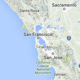
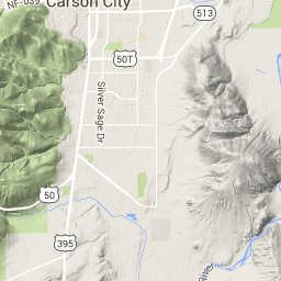
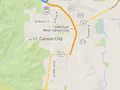
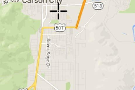
3 Arbor Villas Carson City, NV Preliminary Hydrology Report 1 INTRODUCTION 1.1 Purpose of Analysis This report presents the data, hydrologic and hydraulic analyses, and conclusions of a preliminary technical drainage study performed for Arbor Villas to support the proposed development in Carson City, Nevada. In addition, in the interest of brevity and clarity, this report will defer to figures, tables, and the data and calculations contained in the appendices, whenever possible. 1.2 Project Location and Description The Arbor Villas development is approximately 1.3 acres in size and is located in the southern portion of Carson City and is east of South Stewart Street, south of East 5 th Street, west of South Saliman Road Drive, and north of Little Lane5. Formally, this site is situated within Section 17, Township 15 North, and Range 2 East of the Mount Diablo Meridian (refer to Figure 1, Vicinity Map). The project site is within the existing parcels Project Description The Arbor Villas development is a proposed subdivision which consists of 147 residential units single-family residential units on a 1.31 acre parcel. The project site is currently zoned within the GC zoning district and has an approved tentative map P.U.D. through Carson City. According to Federal Emergency Management Agency (FEMA) Flood Insurance Rate Map (FIRM) Community-Panel Number 32192F, effective date January 19, 214 the subject property is located in Shaded Zone X, which is located with the 5-year floodplain (Appendix A). The purpose of this report is to analyze the existing and proposed conditions of the subject property based on the 5-year and 1-year peak flow events. The report contains the following sections: (1) Methodologies and Assumptions, (2) Existing Hydrology, (3) Proposed Hydrology, and (4) Conclusion. 2 METHODOLOGIES AND ASSUMPTIONS 2.1 Hydrologic Modeling Methods Hydrologic analyses were performed to determine the peak discharge for the 5-year and 1-year peak flow events. Autodesk Sanitary and Storm Analysis (SSA) was used to perform a Rational Method analysis to model the hydrologic basins that contribute in the existing and proposed conditions. Manhard Consulting, Ltd. 1 3/16/216 Project #: POICCNV1 3
4 Arbor Villas Carson City, NV Preliminary Hydrology Report Parameters for peak storm flow and runoff volume estimates presented herein were determined using the data and methodologies presented in the Carson City Municipal Code, Division 14 Storm Drainage section. In instances where the Carson City Municipal Code, Division 14 (CCMC-14) was lacking information or specificity, the Truckee Meadows Regional Drainage Design Manual (29) and/or the other appropriate sources and software user manuals were referenced. For the existing and proposed on-site hydrologic conditions, the Rational Method was utilized in accordance with the CCMC-14. A minimum time of concentration of 1- minutes was used for all sub-basins for a conservative analysis. The rainfall characteristics were modeled using the NOAA database ( to determine site specific depth of precipitation (Appendix A). Rational Formula: Q=CiA Q=Peak Discharge (cfs) C=Runoff Coefficient (dimensionless) i=precipitation Intensity (in/hr) A=Watershed Area (Acres) 2.2 Hydraulic Modeling Methods Hydraulic analyses were performed using the associated hydrologic data to provide the estimates of the elevation of floods for the selected recurrence intervals. Watersurface elevations were computed in SSA using hydrodynamic routing. Hydrodynamic routing solves the complete Saint Venant equations throughout the drainage network and includes modeling of backwater effects, flow reversal, surcharging, looped connections, and pressure flow. Hydrodyanmic routing provides a formulation for channels and pipes, including translation and attenuation effects. 3 EXISTING HYDROLOGIC CONDITIONS 3.1 Existing On-Site Drainage The existing hydrologic analysis was based on the fact that the site was previously disturbed and the existing hydrologic sub-basin was delineated based on the property line. For the existing catchment a time of concentration (Tc) and the Rational Method coefficients were selected, taking into consideration the catchment characteristics, which include catchment area and land cover. A 5-year intensity of 1.46 in/hr and 1-year intensity of 3.53 in/hr were used. Table 1 and Figure 2 summarize the characteristics of on-site catchment of the study area. Reference Appendix B for the existing conditions Rational Method analysis. Reference Figure 2 (Existing Hydrologic Conditions) in the map pocket for existing hydrology drainage map and the associated hydrologic sub-area. Manhard Consulting, Ltd. 2 3/16/216 Project #: POICCNV1 4
5 Arbor Villas Carson City, NV Preliminary Hydrology Report Table 1 Existing Conditions Rational Method Model Summary for the Arbor Villas, Carson City, Nevada. Sub- Basin Area (Ac.) Rational Method Coefficient (C5/C1) Time of Concentration (min) Rainfall Intensity (I5/I1) (in/hr) 5-Year Peak Flows (cfs) 1-Year Peak Flows (cfs) X / / TOTAL The 5-year and 1-year peak flows from on-site catchment in the existing condition are 2.54 cfs and 14.95cfs, respectively. The existing flow discharges in a southeasterly direction and ultimately is conveyed in an existing stormdrain system in Little Lane and routed in an easterly direction. 4 PROPOSED HYDROLOGIC CONDITIONS 4.1 Proposed On-Site Drainage The sub-areas took into account the proposed on-site flows that affect the site. The associated calculated 5-year and 1-year peak flows can be found in Table 2 and Figure 3, the detention facility can be referenced in Tables 3 and Appendix C. Both pipe sizes and catch basins have been sized to accommodate the proposed flows. Reference Figure 3 in the map pocket for the associated hydrologic sub-areas and the proposed catch basins. A 5-year intensity of 1.46 in/hr and 1-year intensity of 3.53 in/hr were used. All drainage for the basins will be contained in swales and the roadway and will travel to the catch basins. From the catch basins, the flow will be routed through the proposed storm drain system. Refer to Appendix C, Proposed Conditions Hydrologic Analysis for all data and supporting calculations using the Rational Method. Assumption: Manhard Consulting made the assumption that the peak flows from Arbor Villas would be conveyed to the existing stormdrain system prior to the peak flows form the upstream basins; therefore, the hydraulic model was terminated at the point where the proposed system connects to the existing system. Manhard Consulting, Ltd. 3 3/16/216 Project #: POICCNV1 5
6 Arbor Villas Carson City, NV Preliminary Hydrology Report Table 2 Proposed Conditions Rational Method Model Summary for the Arbor Villas Project, Carson City, Nevada. Sub- Basin Area (Ac.) Rational Method Coefficient (C5/C1) Time of Concentration (min) Rainfall Intensity (I5/I1) (in/hr) 5-Year Peak Flows (cfs) 1-Year Peak Flows (cfs) BASIN / / BASIN / / BASIN / / BASIN / / BASIN / / BASIN / / BASIN / / BASIN / / BASIN / / BASIN / / BASIN / / BASIN / / BASIN / / BASIN / / BASIN / / BASIN / / BASIN / / BASIN / / BASIN / / BASIN / / TOTAL HYDRAULIC ANALYSIS 5.1 Proposed Drainage Conditions The hydraulic model utilized routing of the peak flows through proposed storm drain and the detention facilities. The runoff is collected in catch basins and detention facilities and routed toward the proposed storm drain system in Parkland and the existing storm drain system in Little Lane. All drainage from the sub-basins will be contained in the lot swales and the roadway and will travel to the catch basins or the detention basins. 5.2 Detention According to the existing and proposed hydrologic analysis, the existing 5-year and 1-year condition flows are 2.54 cfs and cfs, respectively. The proposed 5-year and 1-year condition flows are 8.87 cfs and cfs. However, according to hydraulic analysis, the proposed 5-year and 1-year off-site discharges are 2.65 cfs and cfs, respectively. Therefore, according to CCMC-14, the proposed civil improvements will create a decrease in Manhard Consulting, Ltd. 4 3/16/216 Project #: POICCNV1 6
7 Arbor Villas Carson City, NV Preliminary Hydrology Report the 5-year peak flow runoff of.11 cfs increase and decrease in the 1-year peak flow runoff of 3.6 cfs. The 5-year peak flow increase is due to the basin located directly adjacent to Little Lane which are not routed to the proposed detention facilities. 6 CONCLUSION 6.1 Regulations and Master Plans The proposed improvements and the analyses presented herein are in accordance with drainage regulations presented in Carson City Municipal Code, Division 14 Storm Drainage section. In instances where the Carson City Municipal Code, Division 14 (CCMC-14) was lacking information or specificity, the Truckee Meadows Regional Drainage Design Manual (29) and/or the other appropriate sources and software user manuals were referenced. 6.2 Impacts to Adjacent Properties The performance of the proposed project improvements, roadways, detention/retention, and storm water conveyance facilities, once constructed, will not adversely impact upstream or downstream properties adjacent to this site. The development of this site for the uses proposed will significantly decrease downstream storm flow runoff rates, volumes, velocities, depths, and will not influence floodplain boundaries. 6.3 Standards of Practice This study was prepared using the degree of care and skill ordinarily exercised, under similar circumstances, by reputable professional engineers practicing in this and similar localities. Manhard Consulting, Ltd. 5 3/16/216 Project #: POICCNV1 7
8 PROJECT LOCATION TM PROJ. MGR.: DRAWN BY: DATE: SCALE: CARSON CITY, NEVADA VICINITY MAP FIGURE 1 SHEET OF 8
9 APPENDIX A SUPPORTING DATA 9

10 1


11 11


12 12


13 13
14 APPENDIX B EXISTING CONDITIONS HYDROLOGICAL ANALYSIS 5-YEAR AND 1-YEAR OUTPUT DATA TABLES 14
15 Project Description File Name... Ex-5Year.SPF Description... Arbor Villas Development Project Options Flow Units... CFS Elevation Type... Elevation Hydrology Method... Rational Time of Concentration (TOC) Method... SCS TR-55 Link Routing Method... Hydrodynamic Enable Overflow Ponding at Nodes... YES Skip Steady State Analysis Time Periods... NO Analysis Options Start Analysis On... Jan 22, 216 :: End Analysis On... Jan 23, 216 :: Start Reporting On... Jan 22, 216 :: Antecedent Dry Days... days Runoff (Dry Weather) Time Step... 1:: days hh:mm:ss Runoff (Wet Weather) Time Step... :5: days hh:mm:ss Reporting Time Step... :5: days hh:mm:ss Routing Time Step... 3 seconds Number of Elements Qty Rain Gages... Subbasins... 1 Nodes... 1 Junctions... Outfalls... 1 Flow Diversions... Inlets... Storage Nodes... Links... Channels... Pipes... Pumps... Orifices... Weirs... Outlets... Pollutants... Land Uses... Carson City, Nevada Preliminary Drainage Study Existing 5-year Peak Event Rainfall Details Return Period... 5 year(s) 15
16 Subbasin Summary SN Subbasin Area Weighted Total Total Total Peak Time of ID Runoff Rainfall Runoff Runoff Runoff Concentration Coefficient Volume (ac) (in) (in) (ac-in) (cfs) (days hh:mm:ss) 1 Sub :15: 16
17 Project Description File Name... Ex-1Year.SPF Description... Arbor Villas Development Project Options Flow Units... CFS Elevation Type... Elevation Hydrology Method... Rational Time of Concentration (TOC) Method... SCS TR-55 Link Routing Method... Hydrodynamic Enable Overflow Ponding at Nodes... YES Skip Steady State Analysis Time Periods... NO Analysis Options Start Analysis On... Jan 22, 216 :: End Analysis On... Jan 23, 216 :: Start Reporting On... Jan 22, 216 :: Antecedent Dry Days... days Runoff (Dry Weather) Time Step... 1:: days hh:mm:ss Runoff (Wet Weather) Time Step... :5: days hh:mm:ss Reporting Time Step... :5: days hh:mm:ss Routing Time Step... 3 seconds Number of Elements Qty Rain Gages... Subbasins... 1 Nodes... 1 Junctions... Outfalls... 1 Flow Diversions... Inlets... Storage Nodes... Links... Channels... Pipes... Pumps... Orifices... Weirs... Outlets... Pollutants... Land Uses... Carson City, Nevada Preliminary Drainage Study Existing 1-year Peak Event Rainfall Details Return Period... 1 year(s) 17
18 Subbasin Summary SN Subbasin Area Weighted Total Total Total Peak Time of ID Runoff Rainfall Runoff Runoff Runoff Concentration Coefficient Volume (ac) (in) (in) (ac-in) (cfs) (days hh:mm:ss) 1 Sub :15: 18
19 APPENDIX C PROPOSED CONDITIONS HYDROLOGICAL ANALYSIS 5-YEAR AND 1-YEAR OUTPUT DATA TABLES 19
20 Project Description File Name... Prop-5Year.SPF Description... Arbor Villas Development Project Options Flow Units... CFS Elevation Type... Elevation Hydrology Method... Rational Time of Concentration (TOC) Method... SCS TR-55 Link Routing Method... Hydrodynamic Enable Overflow Ponding at Nodes... YES Skip Steady State Analysis Time Periods... NO Analysis Options Start Analysis On... Mar 16, 216 :: End Analysis On... Mar 17, 216 :: Start Reporting On... Mar 16, 216 :: Antecedent Dry Days... days Runoff (Dry Weather) Time Step... 1:: days hh:mm:ss Runoff (Wet Weather) Time Step... :5: days hh:mm:ss Reporting Time Step... :5: days hh:mm:ss Routing Time Step... 3 seconds Number of Elements Qty Rain Gages... Subbasins... 2 Nodes... 4 Junctions Outfalls... 1 Flow Diversions... Inlets Storage Nodes... 4 Links Channels... Pipes Pumps... Orifices... Weirs... Outlets... Pollutants... Land Uses... Carson City, Nevada Preliminary drainage Study proposed 1-year Peak Event Rainfall Details Return Period... 5 year(s) 2
21 Subbasin Summary SN Subbasin Area Weighted Total Total Total Peak Time of ID Runoff Rainfall Runoff Runoff Runoff Concentration Coefficient Volume (ac) (in) (in) (ac-in) (cfs) (days hh:mm:ss) 1 BASIN :1: 2 BASIN :1: 3 BASIN :1: 4 BASIN :1: 5 BASIN :1: 6 BASIN :1: 7 BASIN :1: 8 BASIN :1: 9 BASIN :1: 1 BASIN :1: 11 BASIN :1: 12 BASIN :1: 13 BASIN :1: 14 BASIN :1: 15 BASIN :1: 16 BASIN :1: 17 BASIN :1: 18 BASIN :1: 19 BASIN :1: 2 BASIN :1: 21
22 Project Description File Name... Prop-1Year.SPF Description... Arbor Villas Development Project Options Flow Units... CFS Elevation Type... Elevation Hydrology Method... Rational Time of Concentration (TOC) Method... SCS TR-55 Link Routing Method... Hydrodynamic Enable Overflow Ponding at Nodes... YES Skip Steady State Analysis Time Periods... NO Analysis Options Start Analysis On... Mar 16, 216 :: End Analysis On... Mar 17, 216 :: Start Reporting On... Mar 16, 216 :: Antecedent Dry Days... days Runoff (Dry Weather) Time Step... 1:: days hh:mm:ss Runoff (Wet Weather) Time Step... :5: days hh:mm:ss Reporting Time Step... :5: days hh:mm:ss Routing Time Step... 3 seconds Number of Elements Qty Rain Gages... Subbasins... 2 Nodes... 4 Junctions Outfalls... 1 Flow Diversions... Inlets Storage Nodes... 4 Links Channels... Pipes Pumps... Orifices... Weirs... Outlets... Pollutants... Land Uses... Carson City, Nevada Preliminary Drainage Study Proposed 1-year Peak Event Rainfall Details Return Period... 1 year(s) 22
23 Subbasin Summary SN Subbasin Area Weighted Total Total Total Peak Time of ID Runoff Rainfall Runoff Runoff Runoff Concentration Coefficient Volume (ac) (in) (in) (ac-in) (cfs) (days hh:mm:ss) 1 BASIN :1: 2 BASIN :1: 3 BASIN :1: 4 BASIN :1: 5 BASIN :1: 6 BASIN :1: 7 BASIN :1: 8 BASIN :1: 9 BASIN :1: 1 BASIN :1: 11 BASIN :1: 12 BASIN :1: 13 BASIN :1: 14 BASIN :1: 15 BASIN :1: 16 BASIN :1: 17 BASIN :1: 18 BASIN :1: 19 BASIN :1: 2 BASIN :1: 23
24 APPENDIX D HYDRAULIC ANALYSES DETENTION CALCUALTIONS 24
25 Project Description File Name... Prop-5Year.SPF Description... Arbor Villas Development Project Options Flow Units... CFS Elevation Type... Elevation Hydrology Method... Rational Time of Concentration (TOC) Method... SCS TR-55 Link Routing Method... Hydrodynamic Enable Overflow Ponding at Nodes... YES Skip Steady State Analysis Time Periods... NO Analysis Options Start Analysis On... Mar 16, 216 :: End Analysis On... Mar 17, 216 :: Start Reporting On... Mar 16, 216 :: Antecedent Dry Days... days Runoff (Dry Weather) Time Step... 1:: days hh:mm:ss Runoff (Wet Weather) Time Step... :5: days hh:mm:ss Reporting Time Step... :5: days hh:mm:ss Routing Time Step... 3 seconds Number of Elements Qty Rain Gages... Subbasins... 2 Nodes... 4 Junctions Outfalls... 1 Flow Diversions... Inlets Storage Nodes... 4 Links Channels... Pipes Pumps... Orifices... Weirs... Outlets... Pollutants... Land Uses... Carson City, Nevada Preliminary drainage Study proposed 1-year Peak Event Rainfall Details Return Period... 5 year(s) 25
26 Storage Nodes Storage Node : POND-1 Input Data Invert Elevation (ft) Max (Rim) Elevation (ft) Max (Rim) Offset (ft) Initial Water Elevation (ft) Initial Water Depth (ft).... Ponded Area (ft²) Evaporation Loss.... Storage Area Volume Curves Storage Curve : POND-1 Stage Storage Storage Area Volume (ft) (ft²) (ft³)
27 27
28 Storage Node : POND-1 (continued) Output Summary Results Peak Inflow (cfs) Peak Lateral Inflow (cfs) Peak Outflow (cfs).... Peak Exfiltration Flow Rate (cfm).... Max HGL Elevation Attained (ft) Max HGL Depth Attained (ft) Average HGL Elevation Attained (ft) Average HGL Depth Attained (ft) Time of Max HGL Occurrence (days hh:mm)... Total Exfiltration Volume (1-ft³)... Total Flooded Volume (ac-in)... Total Time Flooded (min)... Total Retention Time (sec)... :2.. 28
29 Storage Node : POND-2 Input Data Invert Elevation (ft) Max (Rim) Elevation (ft) Max (Rim) Offset (ft) Initial Water Elevation (ft) Initial Water Depth (ft).... Ponded Area (ft²) Evaporation Loss.... Storage Area Volume Curves Storage Curve : POND-2 Stage Storage Storage Area Volume (ft) (ft²) (ft³)
30 3
31 Storage Node : POND-2 (continued) Output Summary Results Peak Inflow (cfs)... Peak Lateral Inflow (cfs)... Peak Outflow (cfs)... Peak Exfiltration Flow Rate (cfm)... Max HGL Elevation Attained (ft)... Max HGL Depth Attained (ft) Average HGL Elevation Attained (ft) Average HGL Depth Attained (ft) Time of Max HGL Occurrence (days hh:mm)... :2 Total Exfiltration Volume (1-ft³).... Total Flooded Volume (ac-in)... Total Time Flooded (min)... Total Retention Time (sec)
32 Storage Node : POND-3 Input Data Invert Elevation (ft) Max (Rim) Elevation (ft) Max (Rim) Offset (ft) Initial Water Elevation (ft) Initial Water Depth (ft).... Ponded Area (ft²) Evaporation Loss.... Storage Area Volume Curves Storage Curve : POND-3 Stage Storage Storage Area Volume (ft) (ft²) (ft³)
33 33
34 Storage Node : POND-3 (continued) Output Summary Results Peak Inflow (cfs) Peak Lateral Inflow (cfs) Peak Outflow (cfs)....3 Peak Exfiltration Flow Rate (cfm).... Max HGL Elevation Attained (ft) Max HGL Depth Attained (ft) Average HGL Elevation Attained (ft) Average HGL Depth Attained (ft) Time of Max HGL Occurrence (days hh:mm)... 1:9 Total Exfiltration Volume (1-ft³).... Total Flooded Volume (ac-in)... Total Time Flooded (min)... Total Retention Time (sec)
35 Storage Node : POND-4 Input Data Invert Elevation (ft) Max (Rim) Elevation (ft) Max (Rim) Offset (ft) Initial Water Elevation (ft) Initial Water Depth (ft).... Ponded Area (ft²) Evaporation Loss.... Storage Area Volume Curves Storage Curve : POND-4 Stage Storage Storage Area Volume (ft) (ft²) (ft³)
36 36
37 Storage Node : POND-4 (continued) Output Summary Results Peak Inflow (cfs) Peak Lateral Inflow (cfs) Peak Outflow (cfs) Peak Exfiltration Flow Rate (cfm).... Max HGL Elevation Attained (ft) Max HGL Depth Attained (ft) Average HGL Elevation Attained (ft) Average HGL Depth Attained (ft) Time of Max HGL Occurrence (days hh:mm)... Total Exfiltration Volume (1-ft³)... Total Flooded Volume (ac-in)... Total Time Flooded (min)... Total Retention Time (sec)... :
38 Project Description File Name... Prop-1Year.SPF Description... Arbor Villas Development Project Options Flow Units... CFS Elevation Type... Elevation Hydrology Method... Rational Time of Concentration (TOC) Method... SCS TR-55 Link Routing Method... Hydrodynamic Enable Overflow Ponding at Nodes... YES Skip Steady State Analysis Time Periods... NO Analysis Options Start Analysis On... Mar 16, 216 :: End Analysis On... Mar 17, 216 :: Start Reporting On... Mar 16, 216 :: Antecedent Dry Days... days Runoff (Dry Weather) Time Step... 1:: days hh:mm:ss Runoff (Wet Weather) Time Step... :5: days hh:mm:ss Reporting Time Step... :5: days hh:mm:ss Routing Time Step... 3 seconds Number of Elements Qty Rain Gages... Subbasins... 2 Nodes... 4 Junctions Outfalls... 1 Flow Diversions... Inlets Storage Nodes... 4 Links Channels... Pipes Pumps... Orifices... Weirs... Outlets... Pollutants... Land Uses... Carson City, Nevada Preliminary Drainage Study Proposed 1-year Peak Event Rainfall Details Return Period... 1 year(s) 38
39 Subbasin Summary SN Subbasin Area Weighted Total Total Total Peak Time of ID Runoff Rainfall Runoff Runoff Runoff Concentration Coefficient Volume (ac) (in) (in) (ac-in) (cfs) (days hh:mm:ss) 1 BASIN :1: 2 BASIN :1: 3 BASIN :1: 4 BASIN :1: 5 BASIN :1: 6 BASIN :1: 7 BASIN :1: 8 BASIN :1: 9 BASIN :1: 1 BASIN :1: 11 BASIN :1: 12 BASIN :1: 13 BASIN :1: 14 BASIN :1: 15 BASIN :1: 16 BASIN :1: 17 BASIN :1: 18 BASIN :1: 19 BASIN :1: 2 BASIN :1: 39
40 Storage Nodes Storage Node : POND-1 Input Data Invert Elevation (ft) Max (Rim) Elevation (ft) Max (Rim) Offset (ft) Initial Water Elevation (ft) Initial Water Depth (ft).... Ponded Area (ft²) Evaporation Loss.... Storage Area Volume Curves Storage Curve : POND-1 Stage Storage Storage Area Volume (ft) (ft²) (ft³)
41 41
42 Storage Node : POND-1 (continued) Output Summary Results Peak Inflow (cfs) Peak Lateral Inflow (cfs) Peak Outflow (cfs).... Peak Exfiltration Flow Rate (cfm).... Max HGL Elevation Attained (ft) Max HGL Depth Attained (ft) Average HGL Elevation Attained (ft) Average HGL Depth Attained (ft) Time of Max HGL Occurrence (days hh:mm)... Total Exfiltration Volume (1-ft³)... Total Flooded Volume (ac-in)... Total Time Flooded (min)... Total Retention Time (sec)... :2.. 42
43 Storage Node : POND-2 Input Data Invert Elevation (ft) Max (Rim) Elevation (ft) Max (Rim) Offset (ft) Initial Water Elevation (ft) Initial Water Depth (ft).... Ponded Area (ft²) Evaporation Loss.... Storage Area Volume Curves Storage Curve : POND-2 Stage Storage Storage Area Volume (ft) (ft²) (ft³)
44 44
45 Storage Node : POND-2 (continued) Output Summary Results Peak Inflow (cfs)... Peak Lateral Inflow (cfs)... Peak Outflow (cfs)... Peak Exfiltration Flow Rate (cfm)... Max HGL Elevation Attained (ft)... Max HGL Depth Attained (ft) Average HGL Elevation Attained (ft) Average HGL Depth Attained (ft) Time of Max HGL Occurrence (days hh:mm)... :2 Total Exfiltration Volume (1-ft³).... Total Flooded Volume (ac-in)... Total Time Flooded (min)... Total Retention Time (sec)
46 Storage Node : POND-3 Input Data Invert Elevation (ft) Max (Rim) Elevation (ft) Max (Rim) Offset (ft) Initial Water Elevation (ft) Initial Water Depth (ft).... Ponded Area (ft²) Evaporation Loss.... Storage Area Volume Curves Storage Curve : POND-3 Stage Storage Storage Area Volume (ft) (ft²) (ft³)
47 47
48 Storage Node : POND-3 (continued) Output Summary Results Peak Inflow (cfs) Peak Lateral Inflow (cfs) Peak Outflow (cfs) Peak Exfiltration Flow Rate (cfm).... Max HGL Elevation Attained (ft) Max HGL Depth Attained (ft) Average HGL Elevation Attained (ft) Average HGL Depth Attained (ft) Time of Max HGL Occurrence (days hh:mm)... :19 Total Exfiltration Volume (1-ft³).... Total Flooded Volume (ac-in)... Total Time Flooded (min)... Total Retention Time (sec)
49 Storage Node : POND-4 Input Data Invert Elevation (ft) Max (Rim) Elevation (ft) Max (Rim) Offset (ft) Initial Water Elevation (ft) Initial Water Depth (ft).... Ponded Area (ft²) Evaporation Loss.... Storage Area Volume Curves Storage Curve : POND-4 Stage Storage Storage Area Volume (ft) (ft²) (ft³)
50 5
51 Storage Node : POND-4 (continued) Output Summary Results Peak Inflow (cfs) Peak Lateral Inflow (cfs) Peak Outflow (cfs)....9 Peak Exfiltration Flow Rate (cfm).... Max HGL Elevation Attained (ft) Max HGL Depth Attained (ft) Average HGL Elevation Attained (ft) Average HGL Depth Attained (ft) Time of Max HGL Occurrence (days hh:mm)... Total Exfiltration Volume (1-ft³)... Total Flooded Volume (ac-in)... Total Time Flooded (min)... Total Retention Time (sec)... :
52 PRELIMINARY SEWER REPORT FOR CARSON CITY, NEVADA Prepared for: Capstone Communities 9441 Double Diamond Pkwy #14 Reno, Nevada Prepared by: Manhard Consulting Ltd. 985 Double R Boulevard Suite 11 Reno, Nevada Project: CCICCNV1 Date: 3/17/16 52
53 Table of Contents 1 INTRODUCTION PROPOSED ALIGNMENT AND QUANTITY OF SERVICE CONCLUSION...2 Appendices Appendix A Manhard Consulting, Ltd. i 3/16/216 Project #: CCICCNV1 53
54 1 INTRODUCTION 1.1 Purpose of Analysis This report represents a detailed analysis of the proposed sanitary sewer system for the Arbor Villas. The purpose of this analysis is to establish peak flow rates and evaluate proposed sanitary sewer sizes for the subject property. 1.2 Project Location and Description The Arbor Villas development is approximately 1.3 acres in size and is located in the southern portion of Carson City and is east of South Stewart Street, south of East 5 th Street, west of South Saliman Road Drive, and north of Little Lane5. Formally, this site is situated within Section 17, Township 15 North, and Range 2 East of the Mount Diablo Meridian (refer to Figure 1, Vicinity Map). The project site is within the existing parcels Figure 2, the Sewer Main Layout, illustrates the location and orientation of the project and its proposed lots and roadway locations. 1.3 Project Description The Arbor Villas Development is a proposed subdivision which consists of 147 single-family residential units. The project site is currently zoned within the GC zoning district and has an approved tentative map P.U.D. through Carson City. 2 PROPOSED ALIGNMENT AND QUANTITY OF SERVICE 2.1 Project Wastewater Collection System Sewage flow from Arbor Villas will be conveyed via public 8 diameter PVC SDR-35 sewer mains to the collection point (manhole) located at the entrance of the development. The sanitary sewer main within the development flows south to the connection of the existing 15- inch sanitary sewer located in Little Lane. All of the mains within the proposed subdivision are located within the rights-of-way of the local roadways. The proposed sizes and locations of the sanitary sewers can be found on the Sanitary Sewer Plan, which is included in this report. The minimum and maximum proposed slopes used within this development are.4% and 1.6%, respectively. These slopes have been checked to ensure that they are within the Carson City required velocity of 2 fps and 1 fps during the peak flow condition. 2.2 Estimated Peak Sewage Flows Calculations for the design of the sewer system were performed in accordance with Chapter 1, Section of the Recommended Standards for Wastewater Facilities, 24 Edition and Division 15, Section of the Carson City Development Standards and Carson City s Sewer Flow Monitoring Analysis (CCSFMA). According to CCSFMA, the actual per capita 1 54
55 flow ranges from gal/cap/day with a peaking factor ranging from For this analysis, the flow factors used in the calculations are 2.5 capita per dwelling unit for a singlefamily residential lot and 15 gal/cap/day to calculate average daily flow. A peaking factor of 3.8 is then applied to the daily average flow to compute the peak flow used in the design of the sanitary sewer. Complete peak flow calculations for Arbor Villas are included within this report. This analysis is considered to be conservative based on the CCSMA results. The following table summarizes the results of the calculations of the peak daily flows for the residential subdivision: Units Capita/DU GPD/ Capita Peaking Factor Peak Flow (gpd) Peak Flow (cfs) , Total 29, Proposed Sewer Mains Basic normal depth calculations for the proposed 8-inch and 1-inch sewer mains were done using open-channel pipe flow theory, the Manning s Formula, and Bentley FlowMaster V8i (FlowMaster) software. A Manning s Coefficient of.13 (assuming PVC pipe material) was used in all of these calculations. The FlowMaster worksheets that demonstrate these calculations are included within this report (Appendix A). Per Carson City Development Standards, sewer mains are considered at capacity when peak flow is at d/d=.75 (Div. 15, Section a.). In addition, the minimum velocity of 2 fps and the maximum velocity of 1 fps are required design conditions (Div 15, Section e.). The FlowMaster calculations included within this report demonstrate that the various velocities of PVC sewer pipe at a d/d of 75% at the minimum and maximum slopes mentioned above are within the requirements for Carson City. The velocity of an 8-inch sewer main is 2.48 fps for a minimum pipe slope of.4% and 2.77 fps for a maximum pipe slope of.5%. All of the calculated velocities described above are within the Carson City required ranged of 2 fps to 1 fps. These velocity calculations can be found in the FlowMaster calculations included within this report. In addition to evaluating the sewer velocities within this development, this report also analyzes maximum capacity within the proposed sewer pipes. As described above, the peak flow within the sewer main must remain at or below a normal depth of 75%. As shown in the FlowMaster calculations included within this report, an 8-inch PVC sewer at.4% can convey 45,42 gpd (.7 cfs) at a maximum depth of 75%. Therefore, each individual neighborhood can be served by an 8-inch sewer system because the maximum sewer loading for the largest neighborhood, Arbor Villas, is 29,475 gpd (.32 cfs), which is less than the maximum allowed capacity of an 8-inch sewer. The size and locations of the proposed sanitary sewers mentioned above can be found on the Sanitary Sewer Plan, which is included in this report. 3 CONCLUSION The 8-inch sanitary sewer mains proposed herein will adequately serve the project as planned. The attached FlowMaster worksheets calculates the maximum capacity of the proposed 8-inch sewer mains at a minimum slope of.4% in accordance with the 2 55
56 requirements of Carson City. The 8-inch sewers at.4% have a capacity of 45,42 gpd (.7 cfs) at a maximum depth of 75%, which will be able to adequately serve Arbor Villas. The proposed sanitary sewerage system within this report for the Arbor Villas development has adequate capacity to carry the subject property s peak sewage flow in conformance with the guidelines outlined in the Carson City Development Standards and the Recommended Standards for Wastewater Facilities. 3 56
57 SANITARY SEWER CALCULATIONS FOR The following calculations were performed in accordance with Chapter 1, Section of the Recommended Standards for Wastewater Facilities, 24 ed. (Ten-States Standards), and the Carson City Development Standards: 2.5 capita/dwelling unit 15 gal/capita/day The site will consist of 147 dwelling units; therefore the following equations are used: Average flow = num. of dwellings * capita/dwelling * GPCD Average flow = 147 * 2.5 * 15 = 55,125 gpd =.9 cfs Peak flow = Average flow * peaking factor Peaking Factor = (18 + P 1/2 ) / (4+P 1/2 ) where P = population in thousands (i.e. dwelling units x 3.5 divided by 1,). Maximum peaking factor is 4.. However, according CCSFMA a peaking factor of 3.8 is acceptable. Calculated peaking factor = 3.8 Peak flow = 55,125 * 3.8 = 29,475 gpd =.32 cfs The design shall be for the peak flow; therefore the design flow is.32 cfs. 57
58 PROJECT LOCATION TM PROJ. MGR.: DRAWN BY: DATE: SCALE: CARSON CITY, NEVADA VICINITY MAP FIGURE 1 SHEET OF 58
59 APPENDIX A FlowMaster Flow Data 59
60 Worksheet for 8" Sewer at.4% Project Description Friction Method Solve For Manning Formula Discharge Input Data Roughness Coefficient.13 Channel Slope.4 ft/ft Normal Depth 6. in Diameter 8. in Results Discharge.7 ft³/s Flow Area.28 ft² Wetted Perimeter 1.4 ft Hydraulic Radius 2.41 in Top Width.58 ft Critical Depth 4.73 in Percent Full 75. % Critical Slope.773 ft/ft Velocity 2.48 ft/s Velocity Head.1 ft Specific Energy.6 ft Froude Number.63 Maximum Discharge.82 ft³/s Discharge Full.76 ft³/s Slope Full.333 ft/ft Flow Type SubCritical GVF Input Data Downstream Depth. in Length. ft Number Of Steps GVF Output Data Upstream Depth. in Profile Description Profile Headloss. ft Average End Depth Over Rise. % Normal Depth Over Rise 75. % Downstream Velocity Infinity ft/s 12/3/215 1:45:45 PM Bentley Systems, Inc. Haestad Methods Solution Bentley Center FlowMaster V8i (SELECTseries 1) [ ] 27 Siemons Company Drive Suite 2 W Watertown, CT 6795 USA Page 1 of 2 6
61 Worksheet for 8" Sewer at.4% GVF Output Data Upstream Velocity Infinity ft/s Normal Depth 6. in Critical Depth 4.73 in Channel Slope.4 ft/ft Critical Slope.773 ft/ft 12/3/215 1:45:45 PM Bentley Systems, Inc. Haestad Methods Solution Bentley Center FlowMaster V8i (SELECTseries 1) [ ] 27 Siemons Company Drive Suite 2 W Watertown, CT 6795 USA Page 2 of 2 61
62 Worksheet for 8" Sewer at.5% Project Description Friction Method Solve For Manning Formula Discharge Input Data Roughness Coefficient.13 Channel Slope.5 ft/ft Normal Depth 6. in Diameter 8. in Results Discharge.78 ft³/s Flow Area.28 ft² Wetted Perimeter 1.4 ft Hydraulic Radius 2.41 in Top Width.58 ft Critical Depth 5.1 in Percent Full 75. % Critical Slope.81 ft/ft Velocity 2.77 ft/s Velocity Head.12 ft Specific Energy.62 ft Froude Number.7 Maximum Discharge.92 ft³/s Discharge Full.85 ft³/s Slope Full.416 ft/ft Flow Type SubCritical GVF Input Data Downstream Depth. in Length. ft Number Of Steps GVF Output Data Upstream Depth. in Profile Description Profile Headloss. ft Average End Depth Over Rise. % Normal Depth Over Rise 75. % Downstream Velocity Infinity ft/s 12/3/215 1:47:59 PM Bentley Systems, Inc. Haestad Methods Solution Bentley Center FlowMaster V8i (SELECTseries 1) [ ] 27 Siemons Company Drive Suite 2 W Watertown, CT 6795 USA Page 1 of 2 62
63 Worksheet for 8" Sewer at.5% GVF Output Data Upstream Velocity Infinity ft/s Normal Depth 6. in Critical Depth 5.1 in Channel Slope.5 ft/ft Critical Slope.81 ft/ft 12/3/215 1:47:59 PM Bentley Systems, Inc. Haestad Methods Solution Bentley Center FlowMaster V8i (SELECTseries 1) [ ] 27 Siemons Company Drive Suite 2 W Watertown, CT 6795 USA Page 2 of 2 63
64 PRELIMINARY WATER MAIN ANALYSIS REPORT FOR CARSON CITY, NEVADA Prepared for: Capstone Communities 9441 Double Diamond Pkwy #14 Reno, Nevada Prepared by: Manhard Consulting Ltd. 985 Double R Boulevard Suite 11 Reno, Nevada Project: CCICCNV1 Date: 3/17/16 64
65 Table of Contents 1 INTRODUCTION PROPOSED ALIGNMENT AND QUANTITY OF SERVICE CONCLUSION... 2 Appendices Appendix A List of Figures Figure 1 Vicinity Map Figure 2 Water Main Layout List of Tables Table 1 Arbor Villas Pressure Summary Manhard Consulting, Ltd. i 3/16/216 Project #: CCICCNV1 65
66 Arbor Villas Carson City, NV Water Main Analysis Report 1 INTRODUCTION 1.1 Purpose of Analysis This report represents a detailed analysis of the proposed water main system for the Arbor Villas. The report describes the water system and the criteria used for design. The purpose of this analysis is to establish the adequacy of the proposed water main pipe diameters and layout to meet the needs of the development. 1.2 Project Location and Description The Arbor Villas development is approximately 1.3 acres in size and is located in the southern portion of Carson City and is east of South Stewart Street, south of East 5 th Street, west of South Saliman Road Drive, and north of Little Lane5. Formally, this site is situated within Section 17, Township 15 North, and Range 2 East of the Mount Diablo Meridian (refer to Figure 1, Vicinity Map). The project site is within the existing parcels Figure 2, the Water Main Layout, illustrates the location and orientation of the project and its proposed lots and roadway locations. 1.3 Project Description The Arbor Villas Development is a proposed subdivision which consists of 147 single-family residential units. The project site is currently zoned within the GC zoning district and has an approved tentative map P.U.D. through Carson City. For purposes of this water main analysis the average lot size for this development is taken to be approximately 1,2 sf. 1.4 Methodologies The Arbor Villas water main analysis was analyzed using WaterGEMS, which employs the Hazen-Williams Method to determine headloss. The Hazen-Williams formula uses a pipe carrying capacity factor (C) based on piping materials. For the Arbor Villas analysis a C- value of 15 was used to model the proposed water main system. 2 PROPOSED ALIGNMENT AND QUANTITY OF SERVICE 2.1 Project Water Main System Two connection points to the existing water system are being utilized for this project. One connection point occurs on Little Lane to the south of the project site and the other occurs on Parkland Avenue. At these points, a proposed 8 water main will connect to an existing stub and looped around the subject property and eventually connecting to the other existing 8 water main. The Arbor Villas development will be served by 8 water main that creates a water system loop for the project (refer to Figure 2, Water Main Layout). Manhard Consulting, Ltd. 1 3/16/216 Project #: POICCNV1 66
67 Arbor Villas Carson City, NV Water Main Analysis Report 2.2 Water Main Analysis The average per lot demand (1. gpm/unit) used in the analysis of the water main system.and NAC 445A A maximum day demand factor of 2. was applied to the average day demand to obtain the maximum day demand (per Tentative Addendum). The peak hour demand was calculated by applying a 1.5 global demand multiplier to the maximum day demands. In a separate analysis, a 15 gpm fire flow requirement was applied to the farthest hydrant in the system from the connection points. This 15 gpm fire flow requirement was obtained from Section B15 and Table B15.1 of the 212 International Fire Code. As a conservative analysis, it was assumed that all of the irrigation zones were active at the same time. The following table provides the high and low pressures that were calculated using WaterGEMS (refer to Appendix B for WaterGEMS output) for each demand condition: Table 1: Arbor Villas Pressure Summary Condition High Pressure (psi) Low Pressure (psi) Max Day Peak Hour Fire Flow (farthest hydrant) 1 83 The maximum day demand low pressure of 13 psi is above the NAC minimum of 4 psi. The peak hour demand low pressure is above the minimum of 64 psi listed in the Carson City Development Standards. The pressure for the various scenarios can be found in the WaterGEMS output included in Appendix B of this report. The fire flow low pressures indicated in the table above are well above the NAC minimum requirement of 2 psi. The pressure at the hydrant H-2 can be found in the WaterGEMS output included in Appendix B of this report. 3 CONCLUSION The analysis of the water system shows that the pipe sizes and layouts within the Arbor Villas Development are adequately designed to meet the demands of the development. The WaterGEMS analysis shows that the pressures are greater than the minimum requirement and below the maximum requirement for Carson City and the NAC requirements. The Arbor Villas Development is in compliance and meets the minimum pressures per NAC 445A.6711 during maximum day, peak hour, and fire flow conditions. Manhard Consulting, Ltd. 2 3/16/216 Project #: POICCNV1 67
68 WATER DEMAND CALCULATIONS FOR Number of units = 41 Average per lot demand = 1. gpm/lot Maximum day demand factor = 2. Peak hour global demand multiplier = 1.5 Average demand = 147*1. = 147. gpm Maximum day demand = 147*2. = 294. gpm Peak hour demand = 294*1.5 = 441. gpm 68
69 PROJECT LOCATION TM PROJ. MGR.: DRAWN BY: DATE: SCALE: CARSON CITY, NEVADA VICINITY MAP FIGURE 1 SHEET OF 69
70 DATE REVISIONS DRAWN BY CHECK BY PROJ. MGR.: PROJ. ASSOC.: DRAWN BY: DATE: SCALE: CARSON CITY, NEVADA SHEET OF PROPOSED WATER DISPLAY 7
71 APPENDIX A 71
72 Scenario Summary Report Scenario: ADD Scenario Summary ID Label Notes Active Topology Physical Demand Initial Settings Operational Age Constituent Trace Fire Flow Energy Cost Transient Pressure Dependent Demand Failure History SCADA User Data Extensions Steady State/EPS Solver Calculation Options Transient Solver Calculation Options 94 ADD <I> Base Active Topology <I> Base Physical ADD <I> Base Initial Settings <I> Base Operational <I> Base Age <I> Base Constituent <I> Base Trace <I> Base Fire Flow <I> Base Energy Cost <I> Base Transient <I> Base Pressure Dependent Demand <I> Base Failure History <I> Base SCADA <I> Base User Data Extensions <I> AVERAGE DAY <I> Base Calculation Options Hydraulic Summary Time Analysis Type Friction Method Accuracy Trials Steady State Hazen- Williams.1 4 Use simple controls during steady state? Is EPS Snapshot? Start Time Calculation Type True False 12:: AM Hydraulics Only.wtg 3/16/216 Bentley Systems, Inc. Haestad Methods Solution Center 27 Siemon Company Drive Suite 2 W Watertown, CT 6795 USA Bentley WaterGEMS V8i (SELECTseries 5) [ ] Page 1 of 1 72
73 FlexTable: Junction Table J-1 J-2 J-3 J-4 J-5 J-6 J-7 J-8 J-9 J-1 J-11 J-12 J-13 J-14 J-15 J-16 J-17 J-18 J-19 J-2 J-21 Label Demand (gpm) Pressure (psi) Hydraulic Grade (ft) 4, , , , , , , , , , , , , , , , , , , , , Zone Elevation (ft) 4,646. 4, , , , , , , , , , , , , , , , , , , , wtg 3/16/216 Bentley Systems, Inc. Haestad Methods Solution Center 27 Siemon Company Drive Suite 2 W Watertown, CT 6795 USA Bentley WaterGEMS V8i (SELECTseries 5) [ ] Page 1 of 1 73
74 FlexTable: Pipe Table Label P-1 P-2 P-3 P-4 P-5 P-6 P-7 P-8 P-9 P-1 P-11 P-12 P-13 P-14 P-15 P-16 P-17 P-18 P-19 P-2 P-21 P-22 P-23 P-24 P-25 Length (Scaled) (ft) Diameter (in) Material Hazen- Williams C Flow (gpm) Velocity (ft/s) Headloss (ft) wtg 3/16/216 Bentley Systems, Inc. Haestad Methods Solution Center 27 Siemon Company Drive Suite 2 W Watertown, CT 6795 USA Bentley WaterGEMS V8i (SELECTseries 5) [ ] Page 1 of 2 74
75 FlexTable: Pipe Table Label P-26 P-27 P-28 P-29 P-3 P-31 Length (Scaled) (ft) Diameter (in) Material Hazen- Williams C Flow (gpm) Velocity (ft/s) Headloss (ft) wtg 3/16/216 Bentley Systems, Inc. Haestad Methods Solution Center 27 Siemon Company Drive Suite 2 W Watertown, CT 6795 USA Bentley WaterGEMS V8i (SELECTseries 5) [ ] Page 2 of 2 75
76 Scenario Summary Report Scenario: MDD Scenario Summary ID Label Notes Active Topology Physical Demand Initial Settings Operational Age Constituent Trace Fire Flow Energy Cost Transient Pressure Dependent Demand Failure History SCADA User Data Extensions Steady State/EPS Solver Calculation Options Transient Solver Calculation Options 95 MDD <I> Base Active Topology <I> Base Physical MDD <I> Base Initial Settings <I> Base Operational <I> Base Age <I> Base Constituent <I> Base Trace <I> Base Fire Flow <I> Base Energy Cost <I> Base Transient <I> Base Pressure Dependent Demand <I> Base Failure History <I> Base SCADA <I> Base User Data Extensions MAX DAY <I> Base Calculation Options Hydraulic Summary Time Analysis Type Friction Method Accuracy Trials Steady State Hazen- Williams.1 4 Use simple controls during steady state? Is EPS Snapshot? Start Time Calculation Type True False 12:: AM Hydraulics Only.wtg 3/16/216 Bentley Systems, Inc. Haestad Methods Solution Center 27 Siemon Company Drive Suite 2 W Watertown, CT 6795 USA Bentley WaterGEMS V8i (SELECTseries 5) [ ] Page 1 of 1 76
77 FlexTable: Junction Table J-1 J-2 J-3 J-4 J-5 J-6 J-7 J-8 J-9 J-1 J-11 J-12 J-13 J-14 J-15 J-16 J-17 J-18 J-19 J-2 J-21 Label Demand (gpm) Pressure (psi) Hydraulic Grade (ft) 4, , , , , , , , , , , , , , , , , , , , , Zone Elevation (ft) 4,646. 4, , , , , , , , , , , , , , , , , , , , wtg 3/16/216 Bentley Systems, Inc. Haestad Methods Solution Center 27 Siemon Company Drive Suite 2 W Watertown, CT 6795 USA Bentley WaterGEMS V8i (SELECTseries 5) [ ] Page 1 of 1 77
Contents. Drainage Analysis: Hunters Trace, Westpointe, and Hunters Creek
 Drainage Analysis: Hunters Trace, Westpointe, and Hunters Creek Contents SITE LOCATION / DESCRIPTION... 3 WESTPOINTE STORMWATER MANAGEMENT PLAN... 3 THE ENCLAVE AT WESTPOINTE DETENTION POND... 3 Table
Woodbury - Aurora Metro Station
 Woodbury - Aurora Metro Station Master Utility Report Aurora, Colorado E. Centrepoint Dr. and E. Alameda Dr. Prepared By: Galloway 6162 S. Willow Drive, Suite 32 Greenwood Village, CO 8111 33.77.8884 POC:
January 20, Nate Hatleback Project Manager, City of Thornton Development Engineering 9500 Civic Center Drive Thornton, CO (303)
") January 20, 2017 Nate Hatleback Project Manager, City of Thornton Development Engineering 9500 Civic Center Drive Thornton, CO 80229 (303) 538-7694 RE: Riverdale Five Retail Drainage Conformance Letter
January 20, 2017 Nate Hatleback Project Manager, City of Thornton Development Engineering 9500 Civic Center Drive Thornton, CO 80229 (303) 538-7694 RE: Riverdale Five Retail Drainage Conformance Letter
Summary of Detention Pond Calculation Canyon Estates American Canyon, California
 July 15, 2015 Bellecci & Associates, Inc Summary of Detention Pond Calculation Canyon Estates American Canyon, California 1. Methodology: Method: Unit Hydrograph Software: Bentley Pond Pack Version 8i
ATTACHMENT 6 WATER QUALITY SWALE DESIGN ADDENDUM
 ATTACHMENT 6 WATER QUALITY SWALE DESIGN ADDENDUM 12 October 2010 Project No. 073-81694.0022 Mr. Robert R. Monok Project Manager Energy Fuels Resource Corporation 44 Union Boulevard, Suite 600 Lakewood,
100-yr Design Runoff (cfs) Basin ID 103b A a B B C Totals
 Basin ID 103b A a B B C Totals") PROPOSED DEVELOPMENT The drainage for this site has been designed to be less than the maximum allowable runoff from each basin as stated in the Overall Rigden Farm drainage plan. Table 1 compares the actual
PROPOSED DEVELOPMENT The drainage for this site has been designed to be less than the maximum allowable runoff from each basin as stated in the Overall Rigden Farm drainage plan. Table 1 compares the actual
City of Fort Collins. Spring Creek Place (2105 South College Avenue) Preliminary Drainage Report
 Preliminary Drainage Report") City of Fort Collins Spring Creek Place (2105 South College Avenue) Preliminary Drainage Report OCTOBER 2016 VERSION 3 Prepared By: 4582 South Ulster Street, Suite 1500 Denver, CO 80237 Daniel L. Skeehan,
City of Fort Collins Spring Creek Place (2105 South College Avenue) Preliminary Drainage Report OCTOBER 2016 VERSION 3 Prepared By: 4582 South Ulster Street, Suite 1500 Denver, CO 80237 Daniel L. Skeehan,
Appendix H: Sewer Capacity Study
 Appendix H: Sewer Capacity Study SoCal Civil Solutions Inc. September 28, 2017 Mr. Taylor Abernathy, PE, CFM City of Orange Public Works - Subdivision Department 300 E. Chapman Avenue Orange, CA 92866
COMPUTER APPLICATIONS HYDRAULIC ENGINEERING
 - 7535 COMPUTER APPLICATIONS IN HYDRAULIC ENGINEERING Connecting Theory to Practice Fifth Edition HAESTAD PRESS Table of Contents Revision History Foreword CHAPTER 1 BASIC HYDRAULIC PRINCIPLES 1 1.1 General
Report. Inflow Design Flood Control System Plan Belle River Power Plant East China, Michigan. DTE Energy Company One Energy Plaza, Detroit, MI
 Report Inflow Design Flood Control System Plan Belle River Power Plant East China, Michigan DTE Energy Company One Energy Plaza, Detroit, MI October 14, 2016 NTH Project No. 62-160047-04 NTH Consultants,
Report. Inflow Design Flood Control System Plan St. Clair Power Plant St. Clair, Michigan. DTE Energy Company One Energy Plaza, Detroit, MI
 Report Inflow Design Flood Control System Plan St. Clair Power Plant St. Clair, Michigan DTE Energy Company One Energy Plaza, Detroit, MI October 14, 2016 NTH Project No. 62-160047-04 NTH Consultants,
BMP Design Aids. w w w. t r a n s p o r t a t i o n. o h i o. g o v. Equations / Programs
 BMP Design Aids 1 Equations / Programs Outlet Discharge Equations Hydrograph and Pond Routing Programs USGS StreamStats 2 Ohio Department of Transportation 1 Training Intent Introduction and overview of
HYDROLOGIC-HYDRAULIC STUDY ISABELLA OCEAN RESIDENCES ISLA VERDE, CAROLINA, PR
 HYDROLOGIC-HYDRAULIC STUDY ISABELLA OCEAN RESIDENCES ISLA VERDE, CAROLINA, PR 1 INTRODUCTION 1.1 Project Description and Location Isabella Ocean Residences is a residential development to be constructed
RETENTION BASIN EXAMPLE
 -7 Given: Total Tributary Area = 7.5 ac o Tributary Area within Existing R/W = 5.8 ac o Tributary Area, Impervious, Outside of R/W = 0.0 ac o Tributary Area, Pervious, Outside of R/W = 1.7 ac o Tributary
PRELIMINARY MUNICIPAL SERVICING REPORT NORTHWOODS SUBDIVISION. Prepared for: North Grassie Properties Inc.
 PRELIMINARY MUNICIPAL SERVICING REPORT SUBDIVISION Prepared for: North Grassie Properties Inc. Prepared by: Stantec Consulting Ltd. 905 Waverley St. Winnipeg, MB R3T 5P4 July 2012 File: 116808030 SUBDIVISION
STORMWATER RUN-ON AND RUN-OFF CONTROL PLAN ENTERGY ARKANSAS, INC. INDEPENDENCE PLANT CLASS 3N CCR LANDFILL
 STORMWATER RUN-ON AND RUN-OFF CONTROL PLAN ENTERGY ARKANSAS, INC. INDEPENDENCE PLANT CLASS 3N CCR LANDFILL PERMIT NO. 0200-S3N-R2 AFIN: 32-00042 OCTOBER 12, 2016 STORMWATER RUN-ON AND RUN-OFF CONTROL PLAN
STORMWATER RUN-ON AND RUN-OFF CONTROL PLAN ENTERGY ARKANSAS, INC. WHITE BLUFF PLANT CLASS 3N CCR LANDFILL
 STORMWATER RUN-ON AND RUN-OFF CONTROL PLAN ENTERGY ARKANSAS, INC. WHITE BLUFF PLANT CLASS 3N CCR LANDFILL PERMIT NO. 199-S3N-R3 AFIN: 3-11 OCTOBER 13, 216 STORMWATER RUN-ON AND RUN-OFF CONTROL PLAN ENTERGY
The site slopes generally from the southwest to northeast at approximately 3.7 percent.
 March 3, 2017 Nate Hatleback Project Manager, City of Thornton Development Engineering 9500 Civic Center Drive Thornton, CO 80229 (303) 538-7694 RE: Riverdale Five Retail Drainage Conformance Letter Dear
CVEN 339 Summer 2009 Final Exam. 120 minutes allowed. 36 Students. No curve applied to grades. Median 70.6 Mean 68.7 Std. Dev High 88 Low 24.
 CVEN 339 Final Exam 120 minutes allowed 36 Students No curve applied to grades Median 70.6 Mean 68.7 Std. Dev. 13.7 High 88 Low 24.5 Name: CVEN 339 Water Resources Engineering Summer Semester 2009 Dr.
Hydrology Study. Ascension Heights Subdivision Ascension Drive at Bel Aire Road San Mateo, California (Unincorporated)
") Hydrology Study Ascension Heights Subdivision Ascension Drive at Bel Aire Road San Mateo, California (Unincorporated) Prepared for San Mateo Real Estate & Construction March 9, 21 Rev. 1 11-8-211 Rev.
Hydrology Study Ascension Heights Subdivision Ascension Drive at Bel Aire Road San Mateo, California (Unincorporated) Prepared for San Mateo Real Estate & Construction March 9, 21 Rev. 1 11-8-211 Rev.
1.1 Purpose of Study Project Description Related Studies Sewage Flows Gravity Sewers...
 Preliminary Wastewater Facilities Plan for Alberhill Villages April 2015 TABLE OF CONTENTS Section Name Page Number Section 1 - Introduction 1.1 Purpose of Study... 1-1 1.2 Project Description... 1-1 1.3
RUN-ON AND RUN-OFF CONTROL SYSTEM PLAN
 RUN-ON AND RUN-OFF CONTROL SYSTEM PLAN FOR THE: SOUTHWESTERN ELECTRIC POWER COMPANY FLINT CREEK POWER PLANT LANDFILL CLASS 3N LANDFILL PERMIT 0273-S3N-R2 PREPARED FOR: SOUTHWESTERN ELECTRIC POWER COMPANY
A Stormwater Management Plan and Sediment Control Plan are required for all proposed developments within the City of Richmond.
 Engineering Page 3-1 3.0 STORM DRAINAGE 3.1 GENERAL Good drainage is vital to flat urban areas such as Lulu Island. It is essential that every storm sewer must be designed accurately minimizing conflicts
Drainage Analysis. Appendix E
 Drainage Analysis Appendix E The existing and proposed storm drainage systems have been modeled with Bentley CivilStorm V8 computer modeling software. The peak stormwater discharge was determined for
Storm Sewer Design. Bob Pitt University of Alabama and Shirley Clark Penn State Harrisburg
 Storm Sewer Design Bob Pitt University of Alabama and Shirley Clark Penn State Harrisburg Major floods are dramatic and water flow routes must be recognized when minor drainage systems fail. These types
APPENDIX G HYDRAULIC GRADE LINE
 Storm Drainage 13-G-1 APPENDIX G HYDRAULIC GRADE LINE 1.0 Introduction The hydraulic grade line is used to aid the designer in determining the acceptability of a proposed or evaluation of an existing storm
SECTION 4 STORM DRAINAGE
 4.01 GENERAL SECTION 4 STORM DRAINAGE These standards shall provide minimum requirements for the design of Storm Drainage and related appurtenances within the City of West Sacramento rights of way and
ENGINEERING REVIEW CHECKLIST City of Mount Clemens
 (To be completed by the Developer s & Submitted with ing Plans) DATE: PROJECT NAME: Site Plan Approved: Date DESIGN ENGINEERING COMPANY: ing Company Contact Information: Name: Phone: Email: Owner Contact
INFLOW DESIGN FLOOD CONTROL SYSTEM PLAN PLANT GREENE COUNTY ASH POND ALABMA POWER COMPANY
 INFLOW DESIGN FLOOD CONTROL SYSTEM PLAN PLANT GREENE COUNTY ASH POND ALABMA POWER COMPANY Section 257.82 of EPA s regulations requires the owner or operator of an existing or new CCR surface impoundment
Chapter 6. Hydrology. 6.0 Introduction. 6.1 Design Rainfall
 6.0 Introduction This chapter summarizes methodology for determining rainfall and runoff information for the design of stormwater management facilities in the City. The methodology is based on the procedures
LAKE COUNTY HYDROLOGY DESIGN STANDARDS
 LAKE COUNTY HYDROLOGY DESIGN STANDARDS Lake County Department of Public Works Water Resources Division 255 N. Forbes Street Lakeport, CA 95453 (707)263-2341 Adopted June 22, 1999 These Standards provide
Storm Water System Improvements
 IV Storm Water System Improvements A. General The purpose of this Section is to establish standard principles and practices for the design and construction of storm drainage facilities within the City
Run-On and Run-Off Control System Plan Neal North Energy Center Monofill
 Run-On and Run-Off Control System Plan Neal North Energy Center Monofill MidAmerican Energy Company, Neal North Energy Center Coal Combustion Residual Rule Compliance October 10, 2016 Run-On and Run-Off
Environmental Design Group
 SEDIMENT CONTROL DURING CONSTRUCTION, STORMWATER MANAGEMENT AND POST CONSTRUCTION BMP REPORT for Hudson Salt Storage and Bus Garage 5810 Hudson Drive HUDSON, OHIO SUMMIT COUNTY Prepared by Environmental
PRELIMINARY DRAINAGE STUDY
 PRELIMINARY DRAINAGE STUDY For 34 th & J Residences 3402 J St. San Diego, CA 92102 A.P.N 545-250-08 Prepared By: Kenneth J. Discenza, P.E. Site Design Associates, Inc. 1016 Broadway, Suite A El Cajon,
HY-12 User Manual. Aquaveo. Contents
 Y-12 User Manual Aquaveo Contents Overview...2 Watershed Parameters...3 Channel Parameters...3 Storm Drain Parameters...3 Design of new systems...4 Analysis of existing systems...4 Steady flow...4 ydrographic
Facilities Development Manual
 State of Wisconsin Department of Transportation Facilities Development Manual ORIGINATOR Director, Bureau of Highway Development PROCEDURE 13-25-35 CHAPTER 13 Drainage SECTION 25 Storm Sewer Design SUBJECT
TABLE OF CONTENTS PART III - MINIMUM DESIGN STANDARDS Section 105 DRAINAGE SYSTEM DESIGN SPECIFICATIONS AND SCOPE 105.1
 TABLE OF CONTENTS PART III - MINIMUM DESIGN STANDARDS Section 105 DRAINAGE SYSTEM DESIGN SECTION TITLE PAGE 105.1. SPECIFICATIONS AND SCOPE 105.1 105.2. METHODS OF ANALYSIS 105.1 105.2.1. Rational Method
INFLOW DESIGN FLOOD CONTROL SYSTEM PLAN PLANT GASTON GYPSUM POND ALABAMA POWER COMPANY
 INFLOW DESIGN FLOOD CONTROL SYSTEM PLAN PLANT GASTON GYPSUM POND ALABAMA POWER COMPANY Section 257.82 of EPA s regulations requires the owner or operator of an existing or new CCR surface impoundment or
November 21, City of Thornton 9500 Civic Center Drive Thornton, CO (303) RE: Maverik Thornton, CO - Drainage Report
 RE: Maverik Thornton, CO - Drainage Report") November 21, 2016 City of Thornton 9500 Civic Center Drive Thornton, CO 80229 (303) 538-7295 RE: Maverik Thornton, CO - Drainage Report As per your request, we are submitting to you the drainage report
November 21, 2016 City of Thornton 9500 Civic Center Drive Thornton, CO 80229 (303) 538-7295 RE: Maverik Thornton, CO - Drainage Report As per your request, we are submitting to you the drainage report
3.9 times the average 3.8 times the average 3.6 times the average
 ARTICLE VI DESIGN OF SANITARY SEWERS M'RSMIN. VOL.281 JA 2 4 2001 IMAGE; Section 601 Determination of the Amount of Sewage for Sanitary Sewers A. MSD Design Standards for estimating sanitary sewage flow
PART 3 - STANDARDS FOR SEWERAGE FACILITIES DESIGN OF STORM SEWERS
 PART 3 - STANDARDS FOR SEWERAGE FACILITIES 3.3 - DESIGN OF STORM SEWERS 3.301 Design of Storm Sewers A. General Information B. Investigations and Surveys C. Special Projects 3.302 Design Criteria for Storm
Preliminary Drainage Analysis
 Preliminary Drainage Analysis Tanimura and Antle Employee Housing Town of Spreckels County of Monterey, California LIB150205 May 29, 2015 Prepared For: Tanimura and Antle Produce Prepared By: 9699 Blue
Hydrologic Study Report for Single Lot Detention Basin Analysis
 Hydrologic Study Report for Single Lot Detention Basin Analysis Prepared for: City of Vista, California August 18, 2006 Tory R. Walker, R.C.E. 45005 President W.O. 116-01 01/23/2007 Table of Contents Page
Learn how to design inlet grates, detention basins, channels, and riprap using the FHWA Hydraulic Toolbox and WMS
 v. 11.0 WMS 11.0 Tutorial Learn how to design inlet grates, detention basins, channels, and riprap using the FHWA Hydraulic Toolbox and WMS Objectives Learn how to use several Hydraulic Toolbox calculators
INFLOW DESIGN FLOOD CONTROL SYSTEM PLAN PLANT BARRY ASH POND ALABAMA POWER COMPANY
 INFLOW DESIGN FLOOD CONTROL SYSTEM PLAN PLANT BARRY ASH POND ALABAMA POWER COMPANY Section 257.82 of EPA s regulations requires the owner or operator of an existing or new CCR surface impoundment or any
Final Drainage Report
 Thornton Electric Substation Project Final Drainage Report December 14, 2016 DRAFT Prepared for: Xcel Energy, 1800 Larimer Street, Suite 400, Denver, Colorado 80202 Prepared by: 350 Indiana Street, Suite
CHAPTER 17: STORM SEWER STANDARDS Introduction Administration Standards 17.1
 CHAPTER 17: STORM SEWER STANDARDS 17.00 Introduction 17.01 Administration 17.02 Standards 17.1 17.00 INTRODUCTION The purpose of this chapter is to provide guidance for the design and construction of storm
FORT COLLINS STORMWATER CRITERIA MANUAL Hydrology Standards (Ch. 5) 1.0 Overview
 1.0 Overview") Chapter 5: Hydrology Standards Contents 1.0 Overview... 1 1.1 Storm Runoff Determination... 1 1.2 Design Storm Frequencies... 1 1.3 Water Quality Storm Provisions... 2 1.4 Design Storm Return Periods...
Chapter 5: Hydrology Standards Contents 1.0 Overview... 1 1.1 Storm Runoff Determination... 1 1.2 Design Storm Frequencies... 1 1.3 Water Quality Storm Provisions... 2 1.4 Design Storm Return Periods...
Introduction to Storm Sewer Design
 A SunCam online continuing education course Introduction to Storm Sewer Design by David F. Carter Introduction Storm sewer systems are vital in collection and conveyance of stormwater from the upstream
Dynamic Analysis - SWMM
 Practice Workbook This workbook is designed for use in Live instructor-led training and for OnDemand self-study. OnDemand videos for this course are available through CONNECT Advisor and on the Bentley
a. Title of Report Example: Final Hydrologic and Hydraulic Drainage Report For Tract #### (or Planning and Zoning Permit ##-###-###)
") CITY OF OXNARD ENGINEERING DIVISION REQUIRED FORMAT AND CONTENTS HYDROLOGIC AND HYDRAULIC DRAINAGE REPORTS This report will provide a basis for design of the drainage system for the subject project. The
CITY OF OXNARD ENGINEERING DIVISION REQUIRED FORMAT AND CONTENTS HYDROLOGIC AND HYDRAULIC DRAINAGE REPORTS This report will provide a basis for design of the drainage system for the subject project. The
Chapter 4. Drainage Report and Construction Drawing Submittal Requirements
 4.0 Introduction The requirements presented in this section shall be used to aid the design engineer or applicant in the preparation of drainage reports, drainage studies, and construction drawings for
Project: Developer/Designer: Reviewer:
 City of Charlottesville, Virginia Engineering Plan Review Checklist (Site Plans, Site Plan Amendments, and Major Subdivisions) 610 East Market Street, Charlottesville, VA 22902 Telephone 434-970-3182;
Chapter 9 Sanitary Sewers
 Chapter 9 Sanitary Sewers I:\AD\030\U30\U30009.docx 4-8-16 Section 9.1 Topic General Requirements Chapter 9 Sanitary Sewers Page 9-1 9.2 Plan Submittals 9-1 9.3 Determination of Flow 9-1 9.4 Facility Design
Hydrology Study. For Bella Terrazza Portion of Lot 1, Block 39, Subdivision of S Tract, Rancho El Cajon El Cajon, CA 92021
 Hydrology Study For Bella Terrazza Portion of Lot 1, Block 39, Subdivision of S Tract, Rancho El Cajon El Cajon, CA 92021 Prepared for Daryl Priest - Priest Development Corporation 124 West Main Street,
Preliminary Drainage Study: Town of Hillsboro Pedestrian & Traffic Safety Project Traffic Calming Project UPC# 70587
 Preliminary Drainage Study: Town of Hillsboro Pedestrian & Traffic Safety Project Traffic Calming Project UPC# 70587 Introduction: The intent of this study was to perform a preliminary drainage study of
Water Resources Management Plan
 P L Y M O U T H M I N N E S O T A Appendix D: The developed a to analyze and minimize the impact of existing and future development on the City s natural resources. It is important to the City to have
Chapter 9 STORMWATER DESIGN. Table 9-1 Hydrology Design Methods
 www.knoxvilletn.gov/engineering/ 9.1 Hydrology Methods Chapter 9 STORMWATER DESIGN Table 9-1 shows the various hydrologic computation methods that can be used to compute peak flows in the City of Knoxville.
Extended Detention Basin Design
 Extended Detention Basin Design 1 Extended Detention 2 Ohio Department of Transportation 1 Extended Detention Basin L&D Vol. 2 Section 1117.3 Provides quality and quantity treatment 3 Extended Detention
Appendix H Amanda Estates Drainage Study
 Appendix H Amanda Estates Drainage Study Hunsaker & Associates 2015 Contents 1 Scope... 1 2 Existing Conditions... 1 3 Project Description... 3 4 Methodology... 5 4.1 Hydrology... 5 4.2 Hydraulics...
Storm Sewers, Page 2
 Storm Sewers storm sewer systems are dendritic systems used to collect and direct stormwater runoff storm sewer systems are integral components of any urban infrastructure curbs, gutters and storm inlets
Stormwater Erosion Control & Post-Construction Plans (Stormwater Quality Plans)
") Stormwater Erosion Control & Post-Construction Plans (Stormwater Quality Plans) Allen County Stormwater Plan Submittal Checklist The following items must be provided when applying for an Allen County Stormwater
Stormwater Erosion Control & Post-Construction Plans (Stormwater Quality Plans) Allen County Stormwater Plan Submittal Checklist The following items must be provided when applying for an Allen County Stormwater
APPENDIX B. WSSC Design Criteria for Water Distribution Systems
 a. System Requirements ) Pressure Requirements APPENDIX B WSSC Design Criteria for Water Distribution Systems a) The water distribution system shall have adequate capacity to supply domestic demand to
ENGN.4010 ENGINEERING CAPSTONE DESIGN Watershed Analysis. CiA
 RATIONAL METHOD Q CiA Where: Q = Maximum Rate of Runoff (cfs) C = Runoff Coefficient i = Average Rainfall Intensity (in/hr) A = Drainage Area (in acres) RATIONAL METHOD Assumptions and Limitations: Watershed
APPENDIX J-3. Orcem Stormwater Management and Treatment Facilities Design Summary
 APPENDIX J-3 Orcem Stormwater Management and Treatment Facilities Design Summary Stormwater Management & Treatment Facilities Design Summary INTRODUCTION KPFF Consulting Engineers has compiled this report
Design Example Residential Subdivision
 Design Example Residential Subdivision Rhode Island Stormwater Design and Installation Standards Manual December 2010 Public Training March 22, 2010 Richard Claytor, P.E. 508-833-6600 Appendix D: Site
3.0 Planning and Submittal Requirements
 October 2003, Revised February 2005 Chapter 3.0, Planning and Submittal Requirements Page 1 3.0 Planning and Submittal Requirements 3.1 Drainage Studies and Drawings The City of Greenwood Village (Village)
Learning objectives. Upon successful completion of this lecture, the participants will be able to:
 Solomon Seyoum Learning objectives Upon successful completion of this lecture, the participants will be able to: Describe and perform the required step for designing sewer system networks Outline Design
PRELIMINARY WASTEWATER CAPACITY STUDY
 PRELIMINARY WASTEWATER CAPACITY STUDY Tentative Tract Map No. 18955 CITY OF HESPERIA Prepared for: HESPERIA VENTURES I, LLC 10410 Roberts Road Calimesa, CA 92320 Tel (714) 785 2381 Mr. John Ohanian Prepared
WASHOE COUNTY COMMUNITY SERVICES DEPARTMENT GRAVITY SEWER COLLECTION DESIGN STANDARDS
 GRAVITY SEWER COLLECTION DESIGN This section of the manual contains the Washoe County Community Services Department (CSD) standards for: INDEX Designing Gravity Sewer Collection Facilities ( Sewer Design
Municipal Stormwater Ordinances Summary Table
 APPENDIX F Municipal Ordinances Summary Table Municipality Abington Bryn Athyn Borough Hatboro Borough Ordinance, SALDO Runoff equals pre post Erosion Sediment Control Water Quality Requirements Any which
INITIAL RUN-ON AND RUN-OFF CONTROL PLAN 40 C.F.R. PART 257
 INITIAL RUN-ON AND RUN-OFF CONTROL PLAN 40 C.F.R. PART 257.81 HUFFAKER ROAD (PLANT HAMMOND) PRIVATE INDUSTRIAL LANDFILL (HUFFAKER ROAD LANDFILL) GEORGIA POWER COMPANY EPA s Disposal of Coal Combustion
Planning Considerations for Stormwater Management in Alberta. R. D. (Rick) Carnduff, M. Eng., P. Eng. February 20, 2013.
 Carnduff, M. Eng., P. Eng. February 20, 2013.") Planning Considerations for Stormwater Management in Alberta R. D. (Rick) Carnduff, M. Eng., P. Eng. February 20, 2013 Photo Optional Purpose The purpose of urban stormwater management is to provide solutions
Planning Considerations for Stormwater Management in Alberta R. D. (Rick) Carnduff, M. Eng., P. Eng. February 20, 2013 Photo Optional Purpose The purpose of urban stormwater management is to provide solutions
DRAINAGE SUBMITTAL CHECKLIST
 Project Name: Firm Name: Map ID: Engineer: Address: City: State: Zip: Phone Number: Fax Number: Property Owner: Address: City: State: Zip: Reviewed By: Date Received: Date Accepted for Review: The following
INITIAL INFLOW DESIGN FLOOD CONTROL SYSTEM PLAN PLANT MCMANUS ASH POND A (AP-1) 40 CFR
 40 CFR") INITIAL INFLOW DESIGN FLOOD CONTROL SYSTEM PLAN PLANT MCMANUS ASH POND A (AP-1) 40 CFR 257.82 EPA s Disposal of Coal Combustion Residuals from Electric Utilities Final Rule (40 C.F.R. Part 257 and Part
INITIAL INFLOW DESIGN FLOOD CONTROL SYSTEM PLAN PLANT MCMANUS ASH POND A (AP-1) 40 CFR 257.82 EPA s Disposal of Coal Combustion Residuals from Electric Utilities Final Rule (40 C.F.R. Part 257 and Part
Haestad Solutions. Bentley Systems Incorporated Haestad Solution Center Watertown, CT Toll-free: Fax:
 1 Haestad Solutions Bentley Systems Incorporated Haestad Solution Center Watertown, CT 06795 Toll-free: 1-800-727-6555 Fax: 203-597-1488 www.bentley.com/www.haestad.com Who was Haestad Methods? World Leader
Stormwater Management Studies PDS Engineering Services Division ES Policy # 3-01
 Stormwater Management Studies PDS Engineering Services Division Revised Date: 2/28/08 INTRODUCTION The City of Overland Park requires submission of a stormwater management study as part of the development
PART V - STORM DRAIN DESIGN CRITERIA
 PART V - STORM DRAIN DESIGN CRITERIA A. Hydrology Studies and Hydraulic Analyses 1. Drainage area master plans and calculations are to be submitted with all subdivision improvement plans, permit improvement
PART V - STORM DRAIN DESIGN CRITERIA
 PART V - STORM DRAIN DESIGN CRITERIA A. Hydrology Studies and Hydraulic Analyses 1. Drainage area master plans and calculations are to be submitted with all subdivision improvement plans, permit improvement
Project Drainage Report
 Design Manual Chapter 2 - Stormwater 2A - General Information 2A-4 Project Drainage Report A. Purpose The purpose of the project drainage report is to identify and propose specific solutions to stormwater
DIVISION 5 STORM DRAINAGE CRITERIA
 DIVISION 5 STORM DRAINAGE CRITERIA Section 5.01 GENERAL The following storm drainage design criteria shall apply to all storm drainage designs in the City. Additional design criteria are specified in the
T a b l e o f C o n t e n t s
 C i t y o f G l a d s t o n e P u b l i c W o r k s D e s i g n S t a n d a r d s T a b l e o f C o n t e n t s SECTION THREE SANITARY SEWER REQUIREMENTS... 1 3.0000 SANITARY SEWERS... 1 3.0010 General
DRAFT. Technical Memorandum. Whitney Road Drainage & Safety Enhancements Phase III Hydraulic Update. Prepared For:
 DRAFT Technical Memorandum Whitney Road Drainage & Safety Enhancements Phase III Hydraulic Update Prepared For: Pinellas County Department of Environment and Infrastructure Division of Engineering and
STORMWATER DESIGN CRITERIA. PUBLIC WORKS DEPARTMENT City of Hudson Oaks, Texas
 STORMWATER DESIGN CRITERIA PUBLIC WORKS DEPARTMENT City of Hudson Oaks, Texas REVISED JANUARY 23, 2014 TABLE OF CONTENTS Foreword.... 3 Storm Water Management Policy.... 4 Definitions.... 5 1. Preliminary
Technical Memorandum - Final
 Technical Memorandum Final Water andenvironment Subject: Tuscany Meadows Offsite Sewerage Impacts Evaluation Prepared For: Patricia Chapman, DDSD Prepared by: Chris van Lienden, RMC Reviewed by: Gisa Ju,
WASHOE COUNTY DEPARTMENT OF WATER RESOURCES GRAVITY SEWER COLLECTION DESIGN STANDARDS
 GRAVITY SEWER COLLECTION DESIGN This section of the manual contains the Washoe County Department of Water Resource s (DWR) standards for: Designing Gravity Sewer Collection Facilities ( Sewer Design Standards
Basics of Wastewater Collection System
 Basics of Wastewater Collection System PDH: 3.0 Hours 1 OUTLINE Introduction Definition of Terms Types of Collections Systems Types of Sewers Shapes of Sewers Collection System Appurtenances Basic Considerations
Detention Pond Design Considering Varying Design Storms. Receiving Water Effects of Water Pollutant Discharges
 Detention Pond Design Considering Varying Design Storms Land Development Results in Increased Peak Flow Rates and Runoff Volumes Developed area Robert Pitt Department of Civil, Construction and Environmental
Chapter 11 Drainage Improvements
 Chapter 11 Drainage Improvements U30011.docx 04/14/17 Chapter 11 Drainage Improvements 11.1 Requirements for Storm Drainage Plans... 1 11.1.1 General... 1 11.1.2 Minor and Major Design Storms... 2 11.1.3
INFLOW DESIGN FLOOD CONTROL SYSTEM PLAN 40 C.F.R. PART PLANT BOWEN ASH POND 1 (AP-1) GEORGIA POWER COMPANY
 GEORGIA POWER COMPANY") INFLOW DESIGN FLOOD CONTROL SYSTEM PLAN 40 C.F.R. PART 257.82 PLANT BOWEN ASH POND 1 (AP-1) GEORGIA POWER COMPANY EPA s Disposal of Coal Combustion Residuals from Electric Utilities Final Rule (40 C.F.R.
INFLOW DESIGN FLOOD CONTROL SYSTEM PLAN 40 C.F.R. PART 257.82 PLANT BOWEN ASH POND 1 (AP-1) GEORGIA POWER COMPANY EPA s Disposal of Coal Combustion Residuals from Electric Utilities Final Rule (40 C.F.R.
MODULE 1 RUNOFF HYDROGRAPHS WORKSHEET 1. Precipitation
 Watershed MODULE 1 RUNOFF HYDROGRAPHS WORKSHEET 1 A watershed is an area of land thaaptures rainfall and other precipitation and funnels it to a lake or stream or wetland. The area within the watershed
SECTION STORM DRAINAGE DESIGN, GRADING, AND WATER QUALITY TECHNICAL CRITERIA TABLE OF CONTENTS PAGE 402 STORM DRAINAGE DESIGN CRITERIA 400-1
 CITY OF THORNTON Standards and Specifications Revised: October 2012 SECTION 400 - STORM DRAINAGE DESIGN, GRADING, AND WATER QUALITY TECHNICAL CRITERIA TABLE OF CONTENTS PAGE 401 GENERAL PROVISIONS 400-1
INFLOW DESIGN FLOOD CONTROL SYSTEM PLAN 40 C.F.R. PART PLANT DANIEL ASH POND B MISSISSIPPI POWER COMPANY
 INFLOW DESIGN FLOOD CONTROL SYSTEM PLAN 40 C.F.R. PART 257.82 PLANT DANIEL ASH POND B MISSISSIPPI POWER COMPANY EPA s Disposal of Coal Combustion Residuals from Electric Utilities Final Rule (40 C.F.R.
CITY OF PANAMA CITY BEACH Utilities Administration & Engineering Offices 116 South Arnold Road Panama City Beach, FL 32413
 Page: 1 of 5 CITY OF PANAMA CITY BEACH Utilities Administration & Engineering Offices 116 South Arnold Road Panama City Beach, FL 32413 COMMERCIAL/RESIDENTIAL UTILITY PLAN COMPLETENESS CHECK LIST Updated
Shawn Herring Civil Applications ProSoft, Inc
 SSA for Highway Design Using Autodesk Storm and Sanitary Analysis for Simple or Complex Roads Shawn Herring Civil Applications Engineer @ ProSoft, Inc Win a Civil 3D Book!!! A Practical Guide to AutoCAD
RE: Final Drainage Letter: Northwest Aurora Alley Improvements 2016
 April 12, 2016 Mr. Craig Perl, P.E. Senior Engineer City of Aurora Public Works Department 15151 E. Alameda Parkway Aurora, CO 80012 RE: Final Drainage Letter: Northwest Aurora Alley Improvements 2016
SITE SERVICING & STORMWATER MANAGEMENT STUDY
 SITE SERVICING & STORMWATER MANAGEMENT STUDY IN SUPPORT OF MAJOR ZONING BY-LAW AMENDMENT AND SITE PLAN CONTROL APPLICAITON Location: 190 Richmond Road, Ottawa, Ontario CPE Project #: 16032 City of Ottawa
TOWN OF MANCHESTER PLANNING AND ZONING COMMISSION Subdivision Application Minimum Submission Requirements
 TOWN OF MANCHESTER PLANNING AND ZONING COMMISSION Subdivision Application Minimum Submission Requirements This checklist is to be completed and submitted with all Subdivision Applications. The Town reserves
St. Boniface Industrial Park Phase 2 Municipal Servicing Report
 St. Boniface Industrial Park Phase 2 Municipal Servicing Report Prepared for: City of Winnipeg Prepared by: Stantec Consulting Ltd. File: 116809351 November 5, 2015 ST. BONIFACE INDUSTRIAL PARK PHASE 2