North Domingo Baca Extension at Barstow
|
|
|
- Darcy Copeland
- 6 years ago
- Views:
Transcription
1 Modeling Report April 5, 2001 North Domingo Baca Extension at Barstow Prepared for the Albuquerque Metropolitan Arroyo Flood Control Authority Julie Coonrod, Ph.D., P.E. Department of Civil Engineering The University of New Mexico
2 Introduction The Domingo Baca Arroyo is located in northeast Albuquerque. The transition structure in question consists of an open channel converging and discharging into a 108 diameter culvert. The 108 diameter culvert is 24 linear feet and discharges into a 96 reinforced concrete pipe running under Carmel Ave., just south of Desert Ridge Middle School. Jeff Mortensen and Associates provided a plan view, profile view, and several sectional views. Those drawings are attached to this report. The existing conditions flow rate is 538 cfs. The future conditions design flow rate is 1166 cfs. Modeling Objective The objective of this project was to build a scale model of the transition structure as shown on the provided design plans, and to use laws of similitude to determine the capacity of the structure. A further objective, which is covered in a subsequent report, is to analyze alternative designs. Designed Transition The provided design documents display plan, profiles, and sections from Station (downstream) to Station (upstream). From Stations to is an earthen transition from a natural sand bed channel to the steep concrete structure leading to a culvert. This channel has a ft/ft bottom slope, 3:1 side slopes, and a bottom width that converges to 40 feet at Station From Stations to is a concrete transition from the earthen channel to the 108-inch diameter culvert. The 108-inch diameter culvert is 24 feet long and discharges to a 96-inch culvert. The culverts do not flow under pressure. The 60-foot long concrete transition structure (Stations to 10+24) was the focus of this study. The invert of the structure drops 13 feet vertically from elevations of to The upstream 30-foot section has a bottom slope of ft/ft. The downstream 30-foot section has a vertical curve as it enters the culvert. The bottom width of the channel varies from 40 feet at Station (upstream) to 16 feet at Station to 9 feet at Station In this same section the side slopes vary from 3:1 (upstream) to vertical at Station The structure from Station to Station has vertical side walls with a 9-foot bottom width. Grout is used in the bottom corners from Station to Station (entrance to the 108-inch culvert) to transition from a rectangular bottom to a circular bottom. The 108-inch culvert does not flow under pressure. 1
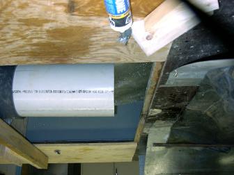
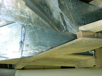
3 Model Froude number similitude is required for open channel models so that the ratio of inertial and gravitational forces is the same for the model and for that which is being modeled. The pump in the lab has a capacity of approximately 2000 gallons per minute (gpm). A scale model, 1:10.8 of the actual size, was built so that the 108 diameter pipe could be modeled with a 10 diameter pipe. The corresponding future conditions design flow rate of 1166 cfs can be modeled using 1365 gpm and the existing conditions flow rate can be modeled using 630 gpm. A larger model (12 diameter pipe) would have required a model flow rate larger than the pump's capacity. Tom Escobedo, UNM Technician, and Gene Valdez, UNM Civil Engineering student, constructed the model according to the instructions given by Dr. Coonrod. The model is shown in Photos 1 and 2. Model Experiments Typically, an open channel is considered to fail when water overtops the channel edge. The model of this transition structure is somewhat unique in that under most conditions the water does not overtop the channel edge. Instead, oblique waves coming down the channel merge in the center as the transition structure steepens. The oblique waves merge with such energy that the water shoots straight up in the middle of the channel. There may be intermittent splashing outside of the channel but the water surface on the channel sides does not encroach the top of the channel. Photos 1 through 8 were taken looking downstream. The oblique waves can be seen merging at approximately Station in Photo 3. Photo 4 shows the moderate jump in the channel with an existing conditions flow rate of approximately 630 gpm (538 cfs). This moderate jump does not exceed the elevation of the sidewalls. Photos 5 through 12 show the model operating at the future conditions flow rate of 1365 gpm (1166 cfs). Under this future conditions flow rate, the height of the water in the middle of the channel exceeds the height of the channel sidewalls; however, the height of water along the sidewalls does not approach the top of the walls. Photo 12 shows the end of the model where the 10 pipe discharges back into the re-circulating tank. 2
4 The large splash can be diminished by dissipating the energy into the transition. A subsequent report reviews alternative designs for the structure. Altering the design with a splitter wall and with a cover (horizontal top wall) were investigated. One splitter wall reduces the splashing for lower flow rates. The splitter wall is shown in Photos The wall begins (upstream) at approximately Station and extends (downstream) to Station where the jump has stopped. However, as the flow rate is increased to the future conditions flow rate of 1365 gpm (1166 cfs), the splashing above the center splitter wall is similar to the splashing without the wall. Altering the open channel by placing a cover extending from Station to allows the transition structure to accommodate flow rates greater than the design flow rates. Photos 16 and 17 show the cover in place. Conclusions & Recommendations The transition structure as shown on the attached plans can accommodate both the existing conditions flow rate of 538 cfs and the future conditions flow rate of 1166 cfs. Little to no splashing is expected under the existing conditions flow rate. Under future conditions flow, intermittent splashing may occur outside of the channel; however, the channel will contain the flow. If the splashing is of concern, the channel can be converted to a culvert from stations to by the addition of a top horizontal slab. 3


5 Photo 1. Photo 4. Photo 2. Photo 5. Photo 3. Photo 6. 4
 Note the")

6 Photo 4. (enlarged) Note the water hitting the cross bar. Photo 5. (enlarged) 5


7 Photo 7. Photo 10. Photo 8. Photo 11. Photo 9. Photo 12. 6


8 Photo 13. Photo 16. Photo 14. Photo 17. Photo 15. 7
Domingo Baca Arroyo crossing at Jefferson
 Modeling Report October 4, 2000 Domingo Baca Arroyo crossing at Jefferson Prepared for the Albuquerque Metropolitan Arroyo Flood Control Authority Julie Coonrod, Ph.D. Department of Civil Engineering The
Lateral Outflow from Supercritical Channels
 Lateral Outflow from Supercritical Channels J. Coonrod 1, J. Ho 2 and N. Bernardo 3 1 Associate Professor, Department of Civil Engineering, University of New Mexico, Albuquerque, NM 87131; PH (505) 277-3233;
Hahn Arroyo Island Project:
 July 2010 Hahn Arroyo Island Project: Hydraulic and Debris Removal Performance Based on Physical Modeling Studies at U M Hydraulics Laboratory Prepared for Albuquerque Metropolitan Arroyo Flood Control
South Diversion Channel Project
 Physical Modeling Report II October 23, 2009 South Diversion Channel Project Recommendations on Flow Diversion System and Structures Based on Physical Model Studies at UNM Hydraulics Laboratory Prepared
Lateral outflow from supercritical channels
 University of New Mexico UNM Digital Repository Civil Engineering ETDs School of Engineering ETDs 9-10-2010 Lateral outflow from supercritical channels Nelson Bernardo Follow this and additional works
(b) Discuss in brief shaft spillway with neat sketches. Marks 04. OR Q (2) Explain in brief USBR stilling basin. Marks 08
 Discuss in brief shaft spillway with neat sketches. Marks 04. OR Q (2) Explain in brief USBR stilling basin. Marks 08") (b) Discuss in brief shaft spillway with neat sketches. Marks 04 OR Q (2) Explain in brief USBR stilling basin. Marks 08 Stilling Basins The basins are usually provided with special appurtenances including
(b) Discuss in brief shaft spillway with neat sketches. Marks 04 OR Q (2) Explain in brief USBR stilling basin. Marks 08 Stilling Basins The basins are usually provided with special appurtenances including
Basic Design of Replogle Flumes
 ITRC Report No. R 02-010 IRRIGATION TRAINING AND RESEARCH CENTER California Polytechnic State University San Luis Obispo, California 93407 www.itrc.org Basic Design of Replogle Flumes Replogle flumes are
Chapter 10. Conduit Outlet Structures Introduction General Layout Information
 10.0 Introduction This section addresses the design of culvert outlets, which are typically oriented in-line with the flow in a drainageway, and storm sewer outlets, which are typically oriented perpendicular
RETENTION BASIN EXAMPLE
 -7 Given: Total Tributary Area = 7.5 ac o Tributary Area within Existing R/W = 5.8 ac o Tributary Area, Impervious, Outside of R/W = 0.0 ac o Tributary Area, Pervious, Outside of R/W = 1.7 ac o Tributary
CLEAR-WATER AND SEDIMENT-LADEN-FLOW TESTING OF THE E-TUBE SEDIMENT RETENTION DEVICE
 CLEAR-WATER AND SEDIMENT-LADEN-FLOW TESTING OF THE E-TUBE SEDIMENT RETENTION DEVICE Prepared for North American Tube Products, Inc. Prepared by Amanda L. Cox Christopher I. Thornton Michael D. Turner October
Drop Height For Channel Erosion Control
 Drop Height For Channel Erosion Control James C.Y. Guo, Professor and Director Department of Civil Engineering, U. of Colorado at Denver, Denver, Colorado 8017 E-mail: James.Guo@cudenver.edu Introduction
Design of Stilling Basin Model with Impact Wall and end Sill
 Abstract Research Journal of Recent Sciences ISSN 2277-2502 Design of Stilling Basin Model with Impact Wall and end Sill Tiwari H.L. Department of Civil Engineering, Maulana Azad National Institute of
Standards for Soil Erosion and Sediment Control in New Jersey May 2012 STANDARD FOR SLOPE PROTECTION STRUCTURES. Definition
 STANDARD FOR SLOPE PROTECTION STRUCTURES Definition Structures to safely conduct surface runoff from the top of a slope to the bottom of the slope. Purpose The purpose of this practice is to convey storm
CHECKLIST FOR STREETS, INLETS, AND STORM SEWER DESIGN
 CHECKLIST FOR STREETS, INLETS, I. STREET CLASSIFICATION AND DESIGN CRITERIA A. Determine drainage classification for the roadway section using Table 7-1 or Table 7-2. B. Determine the allowable flow depth
Flow Measurement Structure Assessment
 Flow Measurement Structure Assessment Report prepared for the Richmond Irrigation District by Eric Leigh, Milton Henry, and Guy Fipps 1 June 2, 2003 Summary Extension Agricultural Engineering investigated
Geneva Dam. Design of a Steep, Temporary, Riprap Ramp
 Geneva Dam Design of a Steep, Temporary, Riprap Ramp A Run-of of-river Dam Analysis for Geneva Dam Credit to: Yu-Chun Su, Ph.D., P.E., CFM David T. Williams. Ph.D., P.E, CFM Presentation Purpose History
7.0 ENERGY DISSIPATION DESIGN
 SPALDING COUNTY, GEORGIA CHAPTER 7 7.0 ENERGY DISSIPATION DESIGN... 7-1 7.1 SYMBOLS AND DEFINITIONS... 7-1 7.2 DESIGN CRITERIA... 7-1 7.2.1 INTRODUCTION... 7-1 7.2.2 GENERAL CRITERIA... 7-2 7.2.3 EROSION
Irrigation System. BWCDD Zanjero Training 2/13/2008
 Irrigation System BWCDD Zanjero Training Session #7 2/13/2008 Irrigation System The (main) intake structure t directs water from the source of supply, such as a reservoir or a river, into the irrigation
Index. outlet protection Rev. 12/93
 6 Index outlet protection level spreader outlet stabilization structure 6.40.1 6.41.1 Rev. 12/93 Practice Standards and Specifications 6.40 level spreader Definition Purpose Conditions Where Practice Applies
Flow Measurement for Structure Assessment in Richmond Irrigation District
 COLLEGE OF AGRICULTURE AND LIFE SCIENCES TR-379 2011 Flow Measurement for Structure Assessment in Richmond Irrigation District By: Eric Leigh, Extension Associate; Milton Henry, Graduate Assistant; and
HYDRAULICS OF CULVERTS
 HYDRAULICS OF CULVERTS Walter F. Silva, Ph.D., P.E. December 8 & 11, 2015 Now you know.. UNIFORM, CRITICAL FLOW and PIPE FLOW Classification of Culvert Flow USGS classifies culvert flow into six types,
Open Channel Flow. Ch 10 Young, Handouts
 Open Channel Flow Ch 10 Young, Handouts Introduction Many Civil & Environmental engineering flows have a free surface open to the atmosphere Rivers, streams and reservoirs Flow in partially filled pipes
Introduction to Storm Sewer Design
 A SunCam online continuing education course Introduction to Storm Sewer Design by David F. Carter Introduction Storm sewer systems are vital in collection and conveyance of stormwater from the upstream
STORM DRAINAGE DESIGN MANUAL
 Appendix I STORM DRAINAGE DESIGN MANUAL by: SUNGATE DESIGN GROUP, P.A. GEN ERAL DESIGN STAN DARDS AN D POLICIES 1. STREET AND LOCAL DRAINAGE Discharge estimates for specified design storms shall be calculated
Hydraulic Modeling with HY-8
 Hydraulic Modeling with HY-8 Linda Hansen PE, PWS MI Dept. of Environmental Quality Water Resources Division UP District Floodplain Engineer Today s Outline What is HY-8? Best Applications & Limitations
Water Control Structures Selected Design Guidelines Alberta Environment Page 17-1
 Alberta Transportation Water Control Structures Selected Design Guidelines Alberta Environment Page 17-1 17.0 MAIN CANAL CONVEYANCE STRUCTURES 17.1 General Conveyance structures typically employed on main
AMERICAN ELECTRIC POWER (SWEPCO)
") 2016 DAM & DIKE INSPECTION REPORT ASH PONDS GERS-16-163 WELSH POWER PLANT AMERICAN ELECTRIC POWER (SWEPCO) CASON, TEXAS NATIONAL INVENTORY NO. TX4357 PREPARED BY GEOTECHNICAL ENGINEERING AEP SERVICE CORPORATION
2016 DAM & DIKE INSPECTION REPORT ASH PONDS GERS-16-163 WELSH POWER PLANT AMERICAN ELECTRIC POWER (SWEPCO) CASON, TEXAS NATIONAL INVENTORY NO. TX4357 PREPARED BY GEOTECHNICAL ENGINEERING AEP SERVICE CORPORATION
of the Crump weir Modelling of composite type variation
 Modelling of composite type variation of the Crump weir Ashley Maritz BEng Honours Student Department of Civil Engineering University of Pretoria aamaritz9@gmail.com Dr Pieter Wessels Specialist Engineer
City of Logan Sanitary Sewer Design Standards
 City of Logan Sanitary Sewer Design Standards 2011 http://www.loganutah.org/public_works/engineering/stdsspecsdesign.cfm Table of Contents PART 1. CITY OF LOGAN SANITARY SEWER SYSTEM DESIGN STANDARDS FOR
Standards for Soil Erosion and Sediment Control in New Jersey May 2012 STANDARD FOR RIPRAP. Conditions Where Practice Applies
 STANDARD FOR RIPRAP Definition A layer of loose rock, aggregate, bagged concrete, gabions, or concrete revetment blocks placed over an erodible soil surface. Purpose The purpose of riprap is to protect
AMERICAN ELECTRIC POWER (SWEPCO)
") 2015 DAM & DIKE INSPECTION REPORT ASH PONDS GERS-15-034 WELSH POWER PLANT AMERICAN ELECTRIC POWER (SWEPCO) CASON, TEXAS NATIONAL INVENTORY NO. TX4357 PREPARED BY GEOTECHNICAL ENGINEERING AEP SERVICE CORPORATION
2015 DAM & DIKE INSPECTION REPORT ASH PONDS GERS-15-034 WELSH POWER PLANT AMERICAN ELECTRIC POWER (SWEPCO) CASON, TEXAS NATIONAL INVENTORY NO. TX4357 PREPARED BY GEOTECHNICAL ENGINEERING AEP SERVICE CORPORATION
Culverts and Flood Gates
 1 of 5 2/15/2011 8:45 AM University of Missouri Extension G1606, Reviewed October 1993 Culverts and Flood Gates C. F. Cromwell, Jr. and Mark Peterson Department of Agricultural Engineering The tables in
Annex I Lyons Ferry Hatchery Modification Plan
 Annex I Lyons Ferry Hatchery Modification Plan Table I1 Figure I1 Figure I2 Figure I3 Figure I4 Figure I5 Well Characteristics Lyons Ferry Hatchery Vicinity Map Lyons Ferry Hatchery Site Plan Water Supply
DRAINAGE SUBMITTAL CHECKLIST
 Project Name: Firm Name: Map ID: Engineer: Address: City: State: Zip: Phone Number: Fax Number: Property Owner: Address: City: State: Zip: Reviewed By: Date Received: Date Accepted for Review: The following
nhc EARTH TECH CANADA INC. CITY OF WINNIPEG NORTH END WATER POLLUTION CONTROL CENTRE PUMP STATION MODEL TEST FINAL REPORT JANUARY 2005
 EARTH TECH CANADA INC. CITY OF WINNIPEG NORTH END WATER POLLUTION CONTROL CENTRE PUMP STATION MODEL TEST FINAL REPORT JANUARY 2005 nhc northwest hydraulic consultants CITY OF WINNIPEG NORTH END WATER POLLUTION
Sump Pumps Office procedures for the Drainage & Grading section
 County of Los Angeles Department of Public Works Building and Safety Division Grading and Drainage Section Sump Pumps Office procedures for the Drainage & Grading section Introduction This manual provides
Flood Hazard Assessment Report Falls Gulch, Larimer County, Colorado January 16, 2013
 United States Department of Agriculture Natural Resources Conservation Service Denver Federal Center Building 56, Room 2604 P.O. Box 25426 Denver, CO 80225 720-544-2818-OFFICE alton.albin@co.usda.gov Flood
SAW MILL RIVER DAYLIGHTING ANALYSIS AT RIVER PARK CENTER
 SAW MILL RIVER DAYLIGHTING ANALYSIS AT RIVER PARK CENTER Prepared for: Struever Fidelco Cappelli LLC McLaren Project No. 6 August 28 TABLE OF CONTENTS. INTRODUCTION 2. SAW MILL RIVER: FEMA STUDY... 2..
Outlet Flow Velocity in Circular Culvert
 Archives of Hydro-Engineering and Environmental Mechanics Vol. 61 (2014), No. 3 4, pp. 193 203 DOI: 10.1515/heem-2015-0013 IBW PAN, ISSN 1231 3726 Outlet Flow Velocity in Circular Culvert Wojciech Szpakowski
INITIAL RUN-ON AND RUN-OFF CONTROL PLAN 40 C.F.R. PART 257
 INITIAL RUN-ON AND RUN-OFF CONTROL PLAN 40 C.F.R. PART 257.81 HUFFAKER ROAD (PLANT HAMMOND) PRIVATE INDUSTRIAL LANDFILL (HUFFAKER ROAD LANDFILL) GEORGIA POWER COMPANY EPA s Disposal of Coal Combustion
UNIT I: UNIFORM FLOW PART B
 UNIT I: UNIFORM FLOW PART-A 1 Define open channel flow with example BT-1-1 2 Distinguish between open channel flow and pipe flow. BT-4-1 3 Compute the hydraulic mean depth of a small channel 1m wide, 0.5m
Chapter 11 Culverts and Bridges
 Chapter 11 Culverts and Bridges Contents 1.0 Introduction... 1 2.0 General Design... 1 2.1 Design Criteria... 1 2.2 Design Flows... 1 2.3 Permitting and Regulations... 1 2.4 Aesthetics and Safety... 2
IMPACT AND PUNCTURING OF JARI TUNNEL AND ENLARGEMENT OF EXISTING TAPPINGS FOR ADDITIONAL WATER SUPPLY AND POWER GENERATION
 117 Paper No. 738 IMPACT AND PUNCTURING OF JARI TUNNEL AND ENLARGEMENT OF EXISTING TAPPINGS FOR ADDITIONAL WATER SUPPLY AND POWER GENERATION JAVED MUNIR, SYED ABBAS ALI, IRFAN MAHMOOD 118 Javed Munir,
PAPERWORK REDUCTION ACT A. GENERAL
 U.S. DEPARTMENT OF HOMELAND SECURITY - FEDERAL EMERGENCY MANAGEMENT AGENCY RIVERINE STRUCTURES FORM O.M.B No. 1660-0016 Expires: 12/31/2010 PAPERWORK REDUCTION ACT Public reporting burden for this form
 DEPARTMENT OF CIVIL ENGINEERING CE6403/ APPLIED HYDRAULIC ENGINEERING QUESTION BANK TWO MARKS UNIT I UNIFORM FLOW 1. Differentiate open channel flow from pipe flow. 2. What is specific energy and is the
Jacobi, Toombs, and Lanz, Inc.
 Area 5: Blackiston Mill Road at Dead Man's Hollow Flooding Assessment Jacobi, Toombs, and Lanz, Inc. This document summarizes an assessment of drainage and flooding concerns and provides recommendations
Low Gradient Velocity Control Short Term Steep Gradient Channel Lining Medium-Long Term Outlet Control Soil Treatment Permanent [1]
![Low Gradient Velocity Control Short Term Steep Gradient Channel Lining Medium-Long Term Outlet Control Soil Treatment Permanent [1]](/thumbs/82/86216855.jpg "Low Gradient Velocity Control Short Term Steep Gradient Channel Lining Medium-Long Term Outlet Control Soil Treatment Permanent [1]") Energy Dissipaters DRAINAGE CONTROL TECHNIQUE Low Gradient Velocity Control Short Term Steep Gradient Channel Lining Medium-Long Term Outlet Control Soil Treatment Permanent [1] [1] The design of permanent
Energy Dissipaters DRAINAGE CONTROL TECHNIQUE Low Gradient Velocity Control Short Term Steep Gradient Channel Lining Medium-Long Term Outlet Control Soil Treatment Permanent [1] [1] The design of permanent
H Y D R A U L I C E F F I C I E N C Y
 2 Hydrology and Economics Hydrologic analysis involves the estimation of a design flow rate based on climatological and watershed characteristics. This analysis is one of the most important aspects of
CE 585 Construction Site Erosion Control The University of Alabama Tuscaloosa, AL. New Chevrolet and Cadillac Dealership Jasper, AL
 CE 585 Construction Site Erosion Control The University of Alabama Tuscaloosa, AL New Chevrolet and Cadillac Dealership Jasper, AL Andrew Kennedy Homework #6 July 24, 2007 0 Table of Contents Table of
Lab 3: Conservation Equations and the Hydraulic Jump
 Lab 3: Conservation Equations and the Hydraulic Jump CEE 330 - Fall 20 SAFETY The major safety hazard in this laboratory is a shock hazard. Given that you will be working with water and items running on
SPILL ESTIMATION. Not Just A Guess Anymore
 SPILL ESTIMATION Not Just A Guess Anymore SPILL ESTIMATION Under current regulations accurate spill estimation has become critical to the operation and maintenance of a sanitary collection system Reporting
20. Security Classif. (of this page) Unclassified Form DOT F (8-72) Reproduction of completed page authorized
 Unclassified Form DOT F (8-72) Reproduction of completed page authorized") 1. Report No. FHWA/TX-06/0-2109-2 Technical Report Documentation Page 2. Government 3. Recipient s Catalog No. Accession No. 4. Title and Subtitle EVALUATION OF HYDRAULIC EFFECTS OF CULVERT SAFETY END
1. Report No. FHWA/TX-06/0-2109-2 Technical Report Documentation Page 2. Government 3. Recipient s Catalog No. Accession No. 4. Title and Subtitle EVALUATION OF HYDRAULIC EFFECTS OF CULVERT SAFETY END
Appendix J: Storm Conveyance Design Parameters
 Appendix J: Storm Conveyance Design Parameters Drain Commissioner 39 February 2005 STORM DRAINAGE DESIGN CRITERIA A. STORM SEWERS 1. The required discharge capacity shall be determined by the Rational
Start and Finish Dates: You will have 90 days from this date in order to complete this course
 Registration form OPERATOR MATH REVIEW $100.00 48 HOUR RUSH ORDER PROCESSING FEE ADDITIONAL $50.00 We will match any other price if you can find equivalent course for less. Start and Finish Dates: You
Green Station CCR Surface Impoundment
 Green Station CCR Surface Impoundment Disposal of Coal Combustion Residuals (CCR) from Electric Utilities Final Rule Hydrologic and Hydraulic Capacity Assessment and Initial Inflow Design Flood Control
DESIGN GRADING AND EROSION CONTROL A. Slope Criteria
 Section 5. DESIGN GRADING AND EROSION CONTROL A. Slope Criteria Earthen slopes shall conform to the following: Maximum slope should not be steeper than 6:1 (horizontal to vertical) unless protected from
Subject: Preliminary fish ladder concept design for Corte Madera Creek flood control channel, for transition between units three and four.
 Page 1 of 18 SENT VIA EMAIL Sandra Guldman Friends of Corte Madera Creek Watershed Box 415 Larkspur, CA 94977 Subject: Corte Madera Creek flood control channel, for transition between units three and four.
RESEARCH AND DEMONSTRATION CENTER ON-LOT SYSTEMS AND SMALL FLOW TECHNOLOGIES DELAWARE VALLEY COLLEGE DOYLESTOWN, PA
 RESEARCH AND DEMONSTRATION CENTER ON-LOT SYSTEMS AND SMALL FLOW TECHNOLOGIES DELAWARE VALLEY COLLEGE DOYLESTOWN, PA Project Funding Provided by: Pennsylvania Dept. of Environmental Protection Thomas J.
Chapter 11 Culverts and Bridges
 Chapter 11 Table of Contents 11-1 Introduction... 1 11-2 General Design... 1 11-2-1 Design Criteria... 1 11-2-2 Design Flows... 1 11-2-3 Permitting and Regulations... 2 11-2-4 Aesthetics and Safety...
Chapter 11 Culverts and Bridges
 Chapter 11 Table of Contents 11-1 Introduction... 1 11-2 General Design... 1 11-2-1 Design Criteria... 1 11-2-2 Design Flows... 1 11-2-3 Permitting and Regulations... 2 11-2-4 Aesthetics and Safety...
INFLOW DESIGN FLOOD CONTROL SYSTEM PLAN 40 C.F.R. PART PLANT YATES ASH POND B (AP-B ) GEORGIA POWER COMPANY
 GEORGIA POWER COMPANY") INFLOW DESIGN FLOOD CONTROL SYSTEM PLAN 40 C.F.R. PART 257.82 PLANT YATES ASH POND B (AP-B ) GEORGIA POWER COMPANY EPA s Disposal of Coal Combustion Residuals from Electric Utilities Final Rule (40 C.F.R.
INFLOW DESIGN FLOOD CONTROL SYSTEM PLAN 40 C.F.R. PART 257.82 PLANT YATES ASH POND B (AP-B ) GEORGIA POWER COMPANY EPA s Disposal of Coal Combustion Residuals from Electric Utilities Final Rule (40 C.F.R.
Surface Skimmer and Baffle Sediment Basins, Modeling the Benefits
 Surface Skimmer and Baffle Sediment Basins, Modeling the Benefits J.P. Johns, PE Woolpert Ray Vaughan Stormwater Manager SCDOT Brandon Wagner -Woolpert Background o SCDOT sediment basin design required
LOW WATER CROSSINGS, fords, or drifts, as they
 Chapter 9 For ords and Low-Water Crossings Keep the ford profile low, armor the driving surface, and protect against scour. LOW WATER CROSSINGS, fords, or drifts, as they are commonly called, can offer
Achieving Uniform Flow Distribution in Compact Irrigation Splitter Boxes with High Flow Rates
 Utah State University DigitalCommons@USU All Graduate Theses and Dissertations Graduate Studies 2016 Achieving Uniform Flow Distribution in Compact Irrigation Splitter Boxes with High Flow Rates Joshua
Lab #3 Conservation Equations and the Hydraulic Jump CEE 331 Fall 2004
 CEE 33 Lab 3 Page of 8 Lab #3 Conservation Equations and the Hydraulic Jump CEE 33 Fall 004 Safety The major safety hazard in this laboratory is a shock hazard. Given that you will be working with water
Appendix I Project Cost Estimates
 Appendix I Project Estimates ropolitan Water Reclamation District of Greater Chicago PCMS-A-Alt2 Structure flooding on Poplar Creek and Lord's Park Tributary. Construct new levee, improve channel for 1,700
Draft. Not Yet Approved SECTION 10.1 GENERAL SCOPE DEFINITIONS
 SECTION 10.1 GENERAL 10.1.1 SCOPE This part of the Manual covers the structural design and installation of reinforced concrete pipe for railway culverts. Pipe geometry may be circular, arch, or elliptical.
MINNEHAHA COUNTY HIGHWAY DEPARTMENT CULVERT REPLACEMENT REQUEST FORM
 MINNEHAHA COUNTY HIGHWAY DEPARTMENT CULVERT REPLACEMENT REQUEST FORM Instructions & Background Information (This page to be completed by Township personnel) The purpose of this form is to provide a means
ROLES AND RESPONSIBILITIES Small Pond Approval. SWM MD-378 Pond Checklist Training 10/17/07. Exemptions EMBANKMENT HEIGHT. Height of Dam Weir Wall
 SWM MD-378 Pond Checklist Training 10/17/07 Ken Wolfe Warren Johnson USDA, NRCS Frederick, Maryland ROLES AND RESPONSIBILITIES Small Pond Approval MDE, WMA, Dam Safety Division Authority (COMAR 26.17.04.03)
INFLOW DESIGN FLOOD CONTROL SYSTEM PLAN 40 C.F.R. Part PLANT MCINTOSH ASH POND 1 GEORGIA POWER COMPANY
 INFLOW DESIGN FLOOD CONTROL SYSTEM PLAN 40 C.F.R. Part 257.82 PLANT MCINTOSH ASH POND 1 GEORGIA POWER COMPANY EPA s Disposal of Coal Combustion Residuals from Electric Utilities Final Rule (40 C.F.R. Part
PERMEABLE INTERLOCKING PAVERS
 PERMEABLE INTERLOCKING PAVERS PART 1 - GENERAL 1.01 SECTION INCLUDES A. Subgrade Preparation B. Placement of Storage Aggregate C. Placement of Filter Aggregate D. Placement of Bedding Course E. Placement
Chapter 9 Hydraulic Structures
 Chapter 9 Hydraulic Structures Contents Structures in Streams... 1 Grade Control Structures... 2 Overview... 2 Simplified Design Procedures for Drop Structures... 4 2.2.1 Introduction... 4 2.2.2 Geometry...
Chapter 5 Hydraulic Structures
 Chapter 5 Hydraulic Structures 5.1 Flow Splitter Designs 5.1.1 General Design Criteria A flow splitter must be designed to deliver the WQ design flow rate specified in this volume to the WQ treatment facility.
CHAPTER 5 WATER SYSTEM DESIGN STANDARDS
 CHAPTER 5 WATER SYSTEM DESIGN STANDARDS TABLE OF CONTENTS CHAPTER 5 WATER SYSTEM DESIGN STANDARDS 5.00 Objective Page 1 5.01 Additional Referenced Standards Page 1 5.02 Special Design Problems Page 2 5.03
VERIFICATION TESTING OF THE HYDROGUARD HG6 HYDRODYNAMIC SEPARATOR STORMWATER TREATMENT UNIT FINAL REPORT. By James T. Mailloux Amie N.
 VERIFICATION TESTING OF THE HYDROGUARD HG6 HYDRODYNAMIC SEPARATOR STORMWATER TREATMENT UNIT FINAL REPORT By James T. Mailloux Amie N. Humphrey Submitted to HYDROWORKS, LLC 2008-332-H1323 December 23, 2008
APPLICATION FORM AF-50: CONSENT UNDER SECTION 50, ARTERIAL DRAINAGE ACT, 1945
 APPLICATION FORM AF-50: CONSENT UNDER SECTION 50, ARTERIAL DRAINAGE ACT, 1945 APPLICATION DETAILS Name of Applicant: Company / authority: Address: Date of Application: Client (if appropriate): BRIDGE DETAILS
INFLOW DESIGN FLOOD CONTROL SYSTEM PLAN PLANT GASTON GYPSUM POND ALABAMA POWER COMPANY
 INFLOW DESIGN FLOOD CONTROL SYSTEM PLAN PLANT GASTON GYPSUM POND ALABAMA POWER COMPANY Section 257.82 of EPA s regulations requires the owner or operator of an existing or new CCR surface impoundment or
PERFORMANCE OF FLOATING HORIZONTAL AERATORS IN AERATED LAGOONS AND OXIDATION DITCHES
 PERFORMANCE OF FLOATING HORIZONTAL AERATORS IN AERATED LAGOONS AND OXIDATION DITCHES PRESENTED ON WEDNESDAY, APRIL 4, 2001 AT THE TEXAS WATER 2001 ANNUAL CONFERENCE LARRY W. MOORE CIVIL ENGINEERING DEPARTMENT
Level 6 Graduate Diploma in Engineering Hydraulics and hydrology
 910-103 Level 6 Graduate Diploma in Engineering Hydraulics and hydrology Sample Paper You should have the following for this examination one answer book ordinary graph paper pen, pencil, ruler Work sheet
- Site Location and Conditions. A. Project Location. B. Existing Conditions
 H&H Report - Site Location and Conditions Page 1 of 2 A. Project Location 1. Site Identification District County Mu nicipali ty 06 Bucks Hilltown (Twp) Site MINSI TRAIL S.R. 4019 Section 60M Segment 0050
Contents. Drainage Analysis: Hunters Trace, Westpointe, and Hunters Creek
 Drainage Analysis: Hunters Trace, Westpointe, and Hunters Creek Contents SITE LOCATION / DESCRIPTION... 3 WESTPOINTE STORMWATER MANAGEMENT PLAN... 3 THE ENCLAVE AT WESTPOINTE DETENTION POND... 3 Table
Preliminary Engineering Report. For the. Foxglove Trail. Prepared for: The City of Moore. Prepared By:
 Preliminary Engineering Report For the Foxglove Trail Prepared for: The City of Moore Prepared By: Certificate of Authorization No. CA#5714 Expires June 30, 2016 CE Project #264 May 2016 City of Moore
III. INVENTORY OF EXISTING FACILITIES
 III. INVENTORY OF EXISTING FACILITIES Within the Growth Management Boundary, the existing storm drainage facilities are largely associated with development that has historically occurred in the ten drainage
Coal Combustion Residuals Inflow Design Flood Control System Plan
 gaiconsultants.com I transforming ideas into reality., Coal Combustion Residuals Inflow Design Flood Control System Plan Virginia Electric and Power Company Possum Point Power Station Surface Impoundment
204 - EXCAVATION AND BACKFILL FOR STRUCTURES SECTION 204 EXCAVATION AND BACKFILL FOR STRUCTURES
 SECTION 204 EXCAVATION AND BACKFILL FOR STRUCTURES 204.1 DESCRIPTION Excavate for the structures as shown in the Contract Documents. Unless specified otherwise, backfill the completed structures to the
VICINITY MAP AND SITE MAP. Page 1 of 9
 INTRODUCTION... 2 1. Background Information of West Bottom Ash Pond (BAP)... 2 1.1 Facility Location Description...2 1.2 Description of West BAP CCR Unit...2 1.2.1 Embankment Configuration...2 1.2.2 Construction
WASTEWATER & STORM WATER COLLECTION AND REMOVAL
 CVE 471 WATER RESOURCES ENGINEERING WASTEWATER & STORM WATER COLLECTION AND REMOVAL Assist. Prof. Dr. Bertuğ Akıntuğ Civil Engineering Program Middle East Technical University Northern Cyprus Campus CVE
PART 3 - STANDARDS FOR SEWERAGE FACILITIES DESIGN OF STORM SEWERS
 PART 3 - STANDARDS FOR SEWERAGE FACILITIES 3.3 - DESIGN OF STORM SEWERS 3.301 Design of Storm Sewers A. General Information B. Investigations and Surveys C. Special Projects 3.302 Design Criteria for Storm
Drainage Report. New Braunfels Municipal Airport. Master Plan Update 2005
 Drainage Report Master Plan Update 2005 General The Texas Department of Transportation (TxDOT), Aviation Division, retained the consulting engineering team of Parkhill, Smith & Cooper, Inc. (PSC), to prepare
3.5 Movable Weirs Movable weir types. Bottom-gate type Figure 3.60 General layout of an offtake weir (Bos 1989).
.") 3.5 Movable Weirs Movable weirs have proven their value for over 80 years in irrigated areas where flow over an off-take structure is variable because of changing crop rotations and water requirements
3.5 Movable Weirs Movable weirs have proven their value for over 80 years in irrigated areas where flow over an off-take structure is variable because of changing crop rotations and water requirements
Stream Restoration at Road Crossings in Northern Wisconsin. Dale Higgins, USDA Forest Service
 Stream Restoration at Road Crossings in Northern Wisconsin Dale Higgins, USDA Forest Service Key Points Large # of road and trail stream crossings on the landscape Many crossings adversely impact streams
Development of a Stage-Discharge Rating for Site Van Bibber Creek at Route 93
 Development of a Stage-Discharge Rating for Site 330 - Van Bibber Creek at Route 93 Prepared for: Urban Drainage and Flood Control District 2480 W. 26 th Avenue Suite 156-B Denver, CO 80211 May 19, 2006
Golder Associates Inc W. Laburnum Avenue, Suite 200 Richmond, VA USA Tel: (804) Fax: (804)
 Fax: (804)") Date: June 1, 014 Made by: DPM Project No.: 130-0193 Checked by: ATN Subject: Leachate Pipe Capacity Reviewed by: JRD Project Short Title: CHESAPEAKE ENERGY CENTER ASH LANDFILL SWP #440 1.0 OBJECTIVE CALCULATIONS
Date: June 1, 014 Made by: DPM Project No.: 130-0193 Checked by: ATN Subject: Leachate Pipe Capacity Reviewed by: JRD Project Short Title: CHESAPEAKE ENERGY CENTER ASH LANDFILL SWP #440 1.0 OBJECTIVE CALCULATIONS
STUDY OF SHAPE OF INTERMEDIATE SILL ON THE DESIGN OF STILLING BASIN MODEL
 STUDY OF SHAPE OF INTERMEDIATE SILL ON THE DESIGN OF STILLING BASIN MODEL H. L. Tiwari 1, Avinash Panwar 2, Bharat Gehlot 3, Jalam Singh 4 1 Department of Civil Engineering, Maulana Azad National Institute
STRUCTURAL STABILITY ASSESSMENT
 STRUCTURAL STABILITY ASSESSMENT CFR 257.73(d) East and West Bottom Ash Pond Pirkey Plant Hallsville, Texas October, 2016 Prepared for: Southwest Electric Power Company (SWEPCO) - Pirkey Plant Hallsville,
Contact the Jurisdictional Engineer for materials allowed by each jurisdiction.
 Design Manual Chapter 3 - Sanitary Sewers 3C - Facility Design 3C-1 Facility Design A. Capacity of Pipe Pipe sizes 15 inches and smaller should carry the peak flow at a depth of no more than 0.67 of the
INFLOW DESIGN FLOOD CONTROL SYSTEM PLAN 40 C.F.R. PART PLANT BOWEN ASH POND 1 (AP-1) GEORGIA POWER COMPANY
 GEORGIA POWER COMPANY") INFLOW DESIGN FLOOD CONTROL SYSTEM PLAN 40 C.F.R. PART 257.82 PLANT BOWEN ASH POND 1 (AP-1) GEORGIA POWER COMPANY EPA s Disposal of Coal Combustion Residuals from Electric Utilities Final Rule (40 C.F.R.
INFLOW DESIGN FLOOD CONTROL SYSTEM PLAN 40 C.F.R. PART 257.82 PLANT BOWEN ASH POND 1 (AP-1) GEORGIA POWER COMPANY EPA s Disposal of Coal Combustion Residuals from Electric Utilities Final Rule (40 C.F.R.
Hancor, Inc. Drainage Handbook Hydraulics 3-1
 Hancor, Inc. Drainage Handbook Hydraulics 3-1 3-0 HYDRAULICS TABLE OF CONTENTS 3-1 Overview of Hydraulic Considerations...3-2 3-2 Design Manning s Value...3-2 3-3 Discharge Curves...3-4 3-3 The Conveyance
SECTION STORM SEWER PIPE
 SECTION 4200 - STORM SEWER PIPE 4200.1 SCOPE: This section covers the requirements for all labor, equipment and materials for the installation of storm sewers pipes. Trenching guidelines are provided in