AMERICAN ELECTRIC POWER (SWEPCO)
|
|
|
- Agatha Clark
- 6 years ago
- Views:
Transcription


1
2 2015 DAM & DIKE INSPECTION REPORT ASH PONDS GERS WELSH POWER PLANT AMERICAN ELECTRIC POWER (SWEPCO) CASON, TEXAS NATIONAL INVENTORY NO. TX4357 PREPARED BY GEOTECHNICAL ENGINEERING AEP SERVICE CORPORATION 1 RIVERSIDE PLAZA COLUMBUS, OHIO December 2015
3 ANNUAL DAM AND DIKE INSPECTION REPORT WELSH POWER PLANT ASH STORAGE PONDS YEAR 2015 GERS INTRODUCTION Background Information Facility Location Description Description of Primary Ash Pond CCR Unit Embankment Configuration Area and Volume Data Construction and Operational History Surface Water Control Background Information Facility Location Description Description of Bottom Ash Storage Pond CCR Unit Embankment Configuration Area/Volume Construction and Operational History Surface Water Control... 4 SUMMARY OF VISUAL OBSERVATIONS... 5 Primary Ash Pond... 5 Active Bottom Ash Storage Pond... 6 ASSESSMENT OF RECENT INSTRUMENTATION DATA... 6 CONCLUSIONS... 6 RECOMMENDATIONS... 7 REMEDIAL ACTIONS... 7 GENERAL MAINTENANCE AND MONITORING... 7 APPENDIX A: APPENDIX B: VICINITY MAP AND PLAN VIEW INSPECTION PHOTOGRAPHS
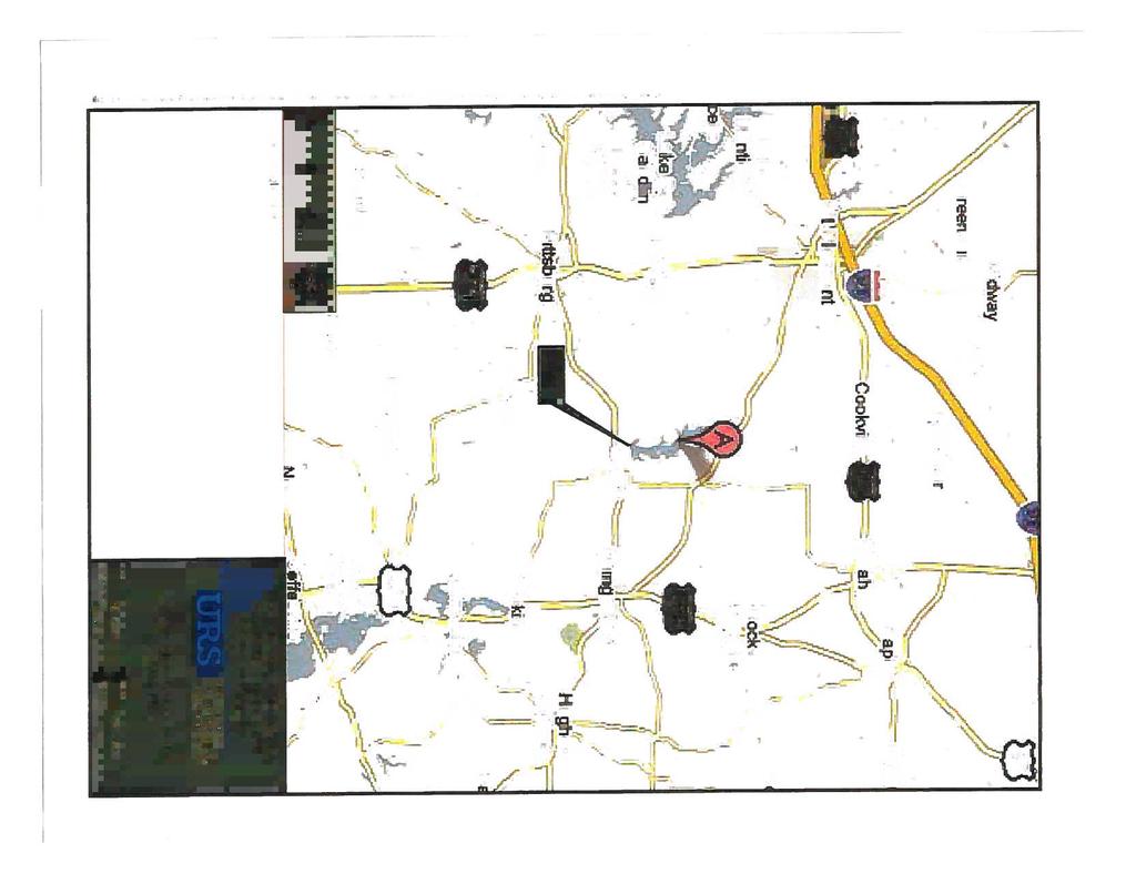
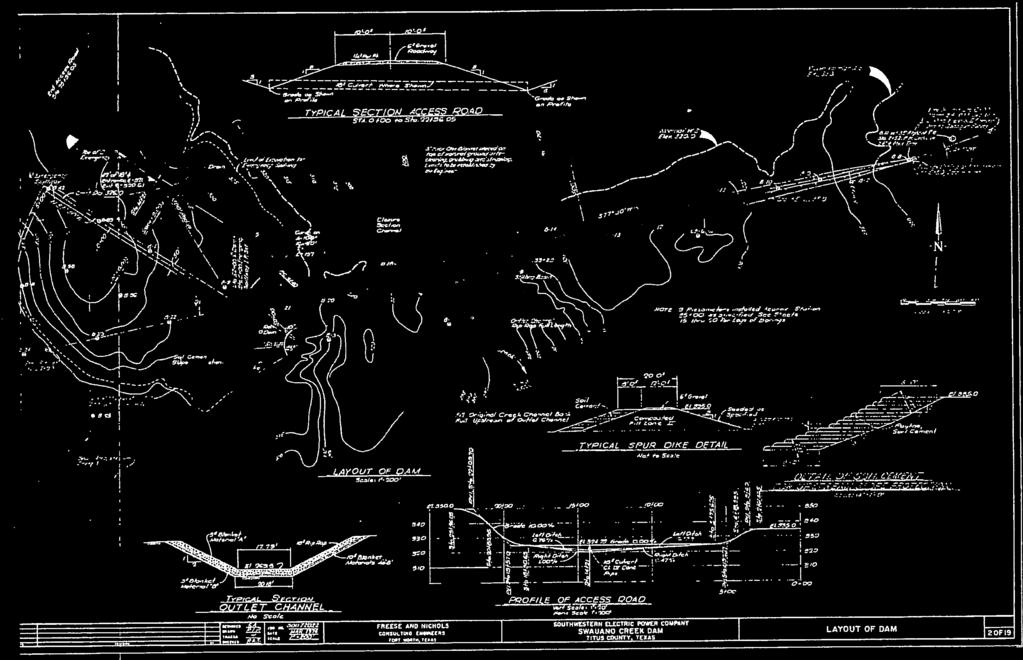
4 INTRODUCTION AEPSC (American Electric Power Service Corporation) Civil Engineering manages the Dam Inspection and Maintenance Program (DIMP) at AEP facilities. As part of the DIMP, staff from the Geotechnical Engineering Section conducts dam and dike inspections annually. The 2015 inspection of Designated CCR Surface Impoundments at the Welsh Power Plant were performed by Mr. Brett A. Dreger, P.E. and Mr. William G. Carter, P.E. This report was prepared by Mr. Brett A. Dreger, P.E. and serves as a summary of the inspection and an assessment of the general conditions of the facility. Mr. William G. Carter, P.E. of AEP Plant Engineering Region 5, was the facility contact for the inspection. The inspection was performed on October 28, Weather conditions were mostly sunny, with temperatures ranging from 70 F in the morning to 84 F in the afternoon. General Information: 1. Background Information The following section provides background information for the AEP J. Robert Welsh Generating Plant primary ash pond. 1.1 Facility Location Description The AEP J. Robert Welsh Plant is located in southern Titus County, approximately 8 miles northeast of Pittsburg, Texas, and approximately two miles northwest of Cason, Texas. The primary ash pond CCR unit is located southwest of the Plant and directly west of the Welsh Reservoir (Figures 1 and 2). 1.2 Description of Primary Ash Pond CCR Unit The following section will discuss the embankment configuration, area, volume, construction and operational history, and surface water control associated with the primary ash pond Embankment Configuration The primary ash pond was placed into operation in 1977, and is located in a topographically low area that had been an unnamed intermittent tributary of Swauano Creek prior to development of the Site. The primary ash pond is bounded by natural ground surface (topographically higher areas) to the north and west, and embankment dikes to the south and east. The elevation at the top of embankment along the crest area is approximately feet above msl. These dikes are predominately constructed of compacted sandy clay and clayey sand. The embankment dike south of the primary ash pond includes a drainage canal that receives overflow (clear) water from the primary ash pond. The water level in the Page 1 of 8
5 primary ash pond is controlled by a weir box which discharges into the drainage canal. The clear water in the drainage canal flows east and discharges into the clear water pond. The primary ash pond embankment is approximately 40 feet in height. Discussions of embankment configuration and timeline, including cross sections through the dikes, was provided in a previous report prepared by ETTL Engineers & Consultants Inc. in 2010 (ETTL, 2010) Area and Volume Data Per the Hydraulic Analysis of Welsh Power Plant Ash Ponds Report, dated December 2010 (Freese and Nichols, 2010), the bottom elevation of the Primary Ash Pond is 300 feet above mean sea level (above msl), the high level overflow weir box bottom elevation is 325 feet above msl, and the storage capacity of the primary ash pond at elevation 325 feet above msl is acre-ft Construction and Operational History The AEP J. Robert Welsh Plant began operations in 1977 with three coal-fired generating units (Units 1, 2, and 3). Throughout the life of the generating plant, CCR materials (fly ash, bottom ash, economizer ash) have been generated. All of these byproducts were stored in either the primary ash pond or in the adjacent landfill that was constructed about In 2000, the 22-acre bottom ash storage pond was installed south of the landfill. The bottom ash storage pond was constructed with a 60-millimeter (mil) high-density polyethylene (HDPE) liner, and receives bottom ash and economizer ash dredged and sluiced from the primary ash pond. Presently, economizer ash from the generating plant is sluiced to the primary ash pond. On occasion, bottom ash is sluiced to the primary ash pond. Solids settle as the clear liquids flow through a drainage canal into the clear water pond (a non-ccr Unit).Water in the clear water pond discharges through a weir box into a 36-inch-diameter pipe, and then into the Welsh Reservoir under Texas Pollutant Discharge Elimination System (TPDES) Permit No. WQ Surface Water Control Surface water flow within the primary ash pond complex is controlled by a weir and emergency spillway located on the south side of the pond below the embankments. The pond elevation is maintained so that surface water flows through the weir box which has a bottom elevation of 325 feet above msl. The emergency spillway is 90 feet wide with a crest elevation of 334 feet above msl. Clear water flows through the weir (and occasionally the emergency spillway during heavy precipitation events) into a drainage canal along the south side of the pond. The drainage canal discharges into the clear water pond located directly southeast of the primary ash pond. Page 2 of 8
6 The perimeter embankments on the south and east sides of the primary ash pond are located at an approximate elevation of 340 feet above msl. Therefore the perimeter embankments have approximately six feet of freeboard above the emergency spillway. 2. Background Information The following section provides background information for the AEP J. Robert Welsh Generating Plant Bottom Ash Storage Pond. 2.1 Facility Location Description The AEP J. Robert Welsh Plant is located in southern Titus County, approximately 8 miles northeast of Pittsburg, Texas, and approximately two miles northwest of Cason, Texas. The Bottom Ash Storage Pond CCR unit is located at the south end of the Plant and approximately 1,000 feet west of the Welsh Reservoir (Figures 1 and 2). 2.2 Description of Bottom Ash Storage Pond CCR Unit The following section will discuss the embankment configuration, area, volume, construction and operational history, and surface water control associated with the Bottom Ash Storage Pond Embankment Configuration The Bottom Ash Storage Pond was placed into operation in 2000, and is located in a topographically high area of the Plant. The Bottom Ash Storage Pond embankments are approximately 20 feet in height and are constructed of compacted clay on a 3:1 slope (3 feet horizontal, 1 foot vertical). The elevation at the base of the embankment is approximately 340 feet above msl, and the elevation at the top of the embankment around the perimeter of the Bottom Ash Storage Pond is approximately 360 feet above msl (Southwestern Electric Power Company, 2000) Area/Volume The Bottom Ash Storage Pond is 22 acres in size. Per the Hydraulic Analysis of Welsh Power Plant Ash Ponds Report, dated December 2010 (Freese and Nichols, 2010), the principal spillway for the Bottom Ash Storage Pond is located near the southeast corner of the pond and consists primarily of an 18 inch drain at elevation feet above msl and also of a 40-foot-long broad-crested weir with a crest elevation of 355 feet above msl. The emergency spillway is an 8-foot-wide weir with a rock rip-rap discharge chute located along the southern embankment at an elevation of 358 feet above msl. The storage capacity of the Bottom Ash Storage Pond at elevation 358 feet above msl is acre-ft (Freese and Nichols, 2010). Page 3 of 8
7 2.2.3 Construction and Operational History The AEP J. Robert Welsh Plant began operations in approximately 1977 with three coalfired generating units (Units 1, 2, and 3). Throughout the life of the generating plant, CCR materials (fly ash, bottom ash, economizer ash) have been generated. All of these byproducts were stored either in the primary ash pond or in the adjacent landfill that was constructed in the late 1970 s. In 2000, the 22-acre Bottom Ash Storage Pond was installed south of the landfill. The Bottom Ash Storage Pond receives bottom ash and economizer ash dredged and sluiced from the primary ash pond. The Bottom Ash Storage Pond contains a 60-millimeter (mil) high-density polyethylene (HDPE) liner. The liner is located at the base of the Bottom Ash Storage Pond at an elevation of 340 feet above msl. The liner also extends along the base of the Bottom Ash Storage Pond sidewalls and is keyed into the top of the Bottom Ash Storage Pond earthen embankment at an elevation of 360 feet above msl (Southwestern Electric Power Company, 2000). The southeast corner of the Bottom Ash Storage Pond contains an approximate ¼-acre clear water pond with a base elevation of 347 feet above msl. The clear water pond receives clear water primarily through an 18 inch drain and then through an overflow structure from the main part of the Bottom Ash Storage Pond through the 40-foot-long broad-crested weir discussed above in Section Water in the ¼-acre clear water pond at the southeast corner of the Bottom Ash Storage Pond discharges through a 30-inch-diameter pipe into the primary ash pond system Surface Water Control Surface water flow within the Bottom Ash Storage Pond is primarily controlled by an 18 inch drain and then by a weir located on the southeast side of the pond below the embankments. The pond elevation is maintained so that surface water flows through the drain pipe at invert elevation feet above msl or weir which has a crest elevation of 355 feet above msl. Clear water flows through the weir into the ¼-acre clear water pond at the southeast corner of the Bottom Ash Storage Pond, then discharges through a 30-inchdiameter pipe into the primary ash pond. The emergency spillway for the Bottom Ash Storage Pond is located along the southern embankment, and is 8 feet wide with a crest elevation of 358 feet above msl. The perimeter embankments of the Bottom Ash Storage Pond are located at an elevation of 360 feet above msl. Therefore the perimeter embankments have approximately five feet of freeboard above the clear water discharge weir, and approximately two feet of freeboard above the emergency spillway. Page 4 of 8
8 SUMMARY OF VISUAL OBSERVATIONS The summary of the visual observations presented herein uses terms to describe the general appearance or condition of an observed item, activity or structure. Their meaning is understood as follows: Good: Fair or satisfactory: Poor: Minor: Significant: Excessive: A condition or activity that is generally better or slightly better than what is minimally expected or anticipated from a design or maintenance point of view. A condition or activity that generally meets what is minimally expected or anticipated from a design or maintenance point of view. A condition or activity that is generally below what is minimally expected or anticipated from a design or maintenance point of view. A reference to an observed item (e.g., erosion, seepage, vegetation, cracks, concrete surface etc.) where the current maintenance condition is below what is normal or desired, but which is not currently causing concern from a structure safety or stability point of view. A reference to an observed item (e.g. erosion, seepage, vegetation, cracks, concrete surface etc.) where the current maintenance program has neglected to improve the condition. Usually, conditions that have been identified in previous inspections, but have not been corrected. A reference to an observed item (e.g., erosion, seepage, vegetation, cracks, concrete surface etc.) where the current maintenance condition is above or worse than what is normal or desired, and which may have affected the ability of the observer to properly evaluate the structure or particular area being observed or which may be a concern from a structure safety or stability point of view. Results of the visual inspection performed on October 28, 2015 are summarized below. Pond water elevation is presented in the instrumentation data section of this report. Primary Ash Pond At the time of inspection the primary ash pond was in service and the current pool elevation was approximately feet above msl. The dikes of the primary ash pond are generally in fair condition, with the only observed deficiency being overgrown vegetation on the downstream side and an abundance of woody vegetation on the inside slopes. The vegetation was so thick on the interior slope, that it was difficult to access and visually inspect. There were no observed signs of slope displacement, erosion, or seepage. The crest was in good condition with no observed cracking, misalignment, or unusual deformation Page 5 of 8
9 (Photographs Nos. 1, 2, and No. 3). The emergency spillway area for the primary pond was in fair and functional condition, but also displayed overgrown vegetation (Photograph No. 4). Active Bottom Ash Storage Pond At the time of inspection the active bottom ash storage pond was in service and the current pool elevation is approximately feet above msl. The Active Bottom Ash Storage Pond exterior slopes were satisfactory condition with no observed sign of slope displacement, erosion or seepage. The slopes were well maintained with vegetation; however, there were a few isolated areas with signs of animal borrow (Photograph No. 5, 6, 7, 8 and No. 10). The emergency spillway section of the pond appeared to be fair and functional condition (Photograph No. 9). The interior area of the pond is lined with white HDPE geomembrane, and there were no observed issues with the crest or interior slopes (Photograph No. 11 and No. 12). ASSESSMENT OF RECENT INSTRUMENTATION DATA The monitoring instrumentation for the Primary Ash Pond of the following: one (1) active piezometer located through the main embankment area. Monitoring instrumentation data is collected as part of the annual inspection program for the Primary Ash Pond. The piezometer level measured during the inspection is provided below. Pond Crest Elevation Boring/Piezometer Water Level Name msl 10/26/2015 msl Primary Ash Pond B A review of the active piezometer readings indicates that the static water level readings are consistent from month to month. CONCLUSIONS Based on the visual inspection, the overall condition of the dams and levees of the Ash Pond Complex is poor to fair. Inspection and monitoring activities being performed by the Plant and AEPSC Civil Engineering & Geotechnical Services should continue. Specific conclusions related to this inspection include: There is no evidence of distress that would indicate the possibility of immediate sliding, slope instability, settlement, misalignment or cracking of the bottom ash pond embankments. As such it is concluded that the dam and dikes are performing as designed. Page 6 of 8
10 Overall, the slope conditions of the dam and levees are generally fair with the exception of animal burrow activity on the bottom ash storage pond. These areas overtime can lead to significant erosion and stability problems. Vegetation management for the facilities is considered poor. Most areas are overgrown and should be managed accordingly, however, there are a few areas that have sparse vegetation. RECOMMENDATIONS Following are remedial actions, general maintenance items and monitoring requirements that are recommended as a result of the inspection. Assistance or guidance with the implementation of these items can be provided by AEPSC Civil Engineering & Geotechnical Services: REMEDIAL ACTIONS Overgrown areas need to be mowed on a regular basis and areas of sparse vegetation need to be reseeded and fertilized in order to establish adequate cover on both the interior and the exterior side slopes. Areas of overgrown vegetation should be well maintained and under control. GENERAL MAINTENANCE AND MONITORING Any erosion gullies, slough areas (shallow slides), and gopher disturbed areas that are encountered should be stabilized as soon as possible. Erosion gullies and slough areas may be stabilized by redressing the slope and placing rip rap or re-vegetating, depending on the slope gradients and propensity for concentrated water flow. Gopher damaged areas should be redressed in the same fashion; A maintenance program of seeding, fertilizing and mulching the slopes of the dam and levees should be implemented. Establishing local grass varieties will prevent erosion and could improve stability of slopes. The local U. S. Dept. of Agriculture Natural Resource Conservation Service (NRCS) office can provide suitable seed mix design for the local climate and soils; Page 7 of 8
11 The slopes of the ash pond dikes should be maintained free of brush and woody vegetation; Monitoring procedures and maintenance activities should be implemented in coordination with AEP Geotechnical Group; Continue Plant inspections of the facility in accordance with the Circular Letter and CCR Rules. Based on the inspection and review of relevant documents, AEPSC Civil Engineering believes that the Welsh Primary Ash Pond and the Bottom Ash Storage Area have a general satisfactory appearance and are in fair condition. Inspections and monitoring should continue. If you have any questions with regard to this report, please do not hesitate to contact Brett A. Dreger at (614) (Audinet ). Page 8 of 8
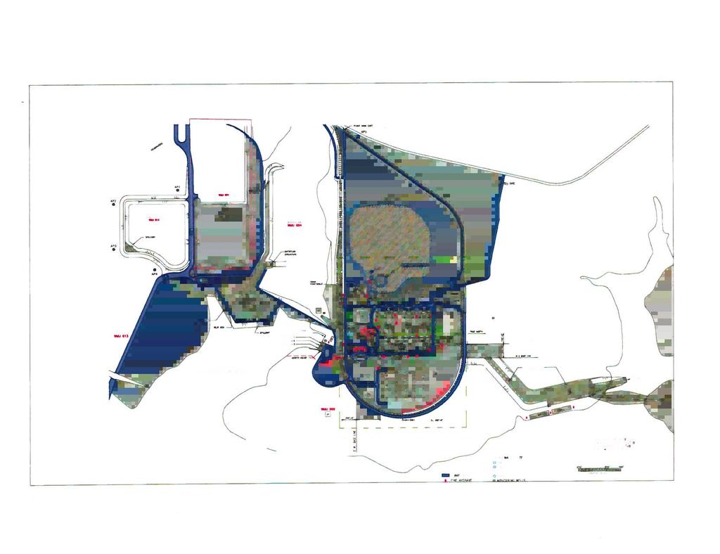
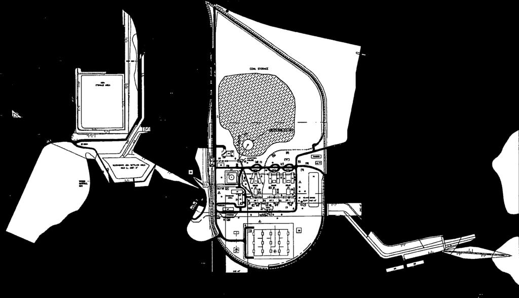
12 APPENDIX A VICINITY MAP AND PLAN VIEW


13

14


15
16 APPENDIX B INSPECTION PHOTOGRAPHS


17 October 28, 2015 Welsh Power Plant Dam and Dike Inspections Page 1 Photo # 1 Typical view of primary ash pond upstream slope and interior conditions. Photo # 2 Typical view of primary ash pond downstream slope. Photo # 3 Typical crest area of primary ash pond.


18 October 28, 2015 Welsh Power Plant Dam and Dike Inspections Page 2 Photo # 4 Emergency spillway channel of primary ash pond. Photo # 5 Active ash storage area (Winston Pond) downstream slope southeast area. Photo # 6 Active ash storage area (Winston Pond) downstream slope southeast area.

")
")
19 October 28, 2015 Welsh Power Plant Dam and Dike Inspections Page 3 Photo # 7 Active ash storage area (Winston Pond) downstream slope south area. Photo # 8 Active ash storage area (Winston Pond) downstream slope west area. Photo # 9 Active ash storage area (Winston Pond) downstream slope looking at emergency spillway channel.

.")

20 October 28, 2015 Welsh Power Plant Dam and Dike Inspections Page 4 Photo # 10 Animal activity/burrow on exterior slope area (Winston Pond). Photo # 11 Active ash storage area (Winston Pond) looking at typical interior conditions. Photo # 12 Active ash storage area (Winston Pond) interior slopes looking north.
Mr. Michael Malone CPS Energy 145 Navarro Street San Antonio, Texas Project No
 Environmental Resources Management January 13, 2017 Mr. Michael Malone 145 Navarro Street San Antonio, Texas 78205 Project No. 0352436 CityCentre Four 840 West Sam Houston Parkway North, Suite 600 Houston,
2016 LANDFILL INSPECTION REPORT CARDINAL PLANT BRILLIANT, OHIO
 2016 LANDFILL INSPECTION REPORT GERS-16-004 CARDINAL PLANT BRILLIANT, OHIO PREPARED BY GEOTECHNICAL ENGINEERING AEP SERVICE CORPORATION 1 RIVERSIDE PLAZA COLUMBUS, OHIO Cardinal Plant Landfill Inspection
2016 Annual Dam and Dike Inspection Report
 2016 Annual Dam and Dike Inspection Report Fly Ash Pond John E. Amos Plant Appalachian Power Co. Putnam County, West Virginia November, 2016 Prepared for: Appalachian Power Co. 1530 Winfield Rd Winfield,
Table of Contents. Attachments Attachment A Photos Attachment B Site Map. Pages 3 of 9
 Table of Contents 1.0 Introduction...4 2.0 Description of Landfill...4 3.0 Review of Available Information...5 4.0 Inspection...5 4.1 Changes in Geometry since Last Inspection...5 4.2 Volume...5 4.3 Definitions
Table of Contents. Attachments Attachment A Photos Attachment B Inspection Map. Pages 3 of 10
 Table of Contents 1.0 Introduction...4 2.0 Description of Landfill...4 3.0 Review of Available Information...5 4.0 Inspection...5 4.1 Changes in Geometry since Last Inspection...5 4.2 Volume...5 4.3 Definitions
DTE Energy St. Clair Power Plant
 DTE Energy St. Clair Power Plant Unit 6 Scrubber Basins CCR Rule Compliance Project Annual Inspection Report - 2017 Project Number: 60546402 June 30, 2017 Prepared by: 27777 Franklin Road, Suite 2000 Southfield,
CLOSURE PLAN. CFR (b) Document No. GERS Stingy Run Flyash Pond. Gavin Plant Cheshire, Ohio. October, 2016
 Document No. GERS Stingy Run Flyash Pond. Gavin Plant Cheshire, Ohio. October, 2016") CLOSURE PLAN CFR 257.102(b) Stingy Run Flyash Pond Gavin Plant Cheshire, Ohio October, 2016 Prepared for: AEP Generation Resources Gavin Plant Cheshire, Ohio Prepared by: American Electric Power Service
CLOSURE PLAN CFR 257.102(b) Stingy Run Flyash Pond Gavin Plant Cheshire, Ohio October, 2016 Prepared for: AEP Generation Resources Gavin Plant Cheshire, Ohio Prepared by: American Electric Power Service
CCR Annual Inspection (b) for the Ash Pond at the San Miguel Plant. Revision 0
 for the Ash Pond at the San Miguel Plant. Revision 0") Submitted to San Miguel Electric Cooperative, Inc. 6200 FM 3387 Christine, Texas 78012 Submitted by AECOM 9400 Amberglen Boulevard Austin, Texas 78729 257.83 (b) for the Ash Pond at the San Miguel Plant
Submitted to San Miguel Electric Cooperative, Inc. 6200 FM 3387 Christine, Texas 78012 Submitted by AECOM 9400 Amberglen Boulevard Austin, Texas 78729 257.83 (b) for the Ash Pond at the San Miguel Plant
Lyon Creek Cedar Way Stormwater Detention Dam Operation and Maintenance Manual
 Lyon Creek Cedar Way Stormwater Detention Dam Operation and Maintenance Manual Prepared by: Mike Shaw Stormwater Program Manager City of Mountlake Terrace January 2010 Section I General Information This
POST CLOSURE PLAN. CFR (d) GERS Landfill. Pirkey Plant Hallsville, Texas. October, 2016
 GERS Landfill. Pirkey Plant Hallsville, Texas. October, 2016") POST CLOSURE PLAN CFR 257.104(d) Landfill Pirkey Plant Hallsville, Texas October, 2016 Prepared for : Southwest Electric Power Company Pirkey Power Plant Hallsville, Texas Prepared by: American Electric
POST CLOSURE PLAN CFR 257.104(d) Landfill Pirkey Plant Hallsville, Texas October, 2016 Prepared for : Southwest Electric Power Company Pirkey Power Plant Hallsville, Texas Prepared by: American Electric
2016 ANNUAL DAM AND DIKE INSPECTION REPORT
 2016 ANNUAL DAM AND DIKE INSPECTION REPORT Fly Ash Dams 1, 2 & Bottom Ash Pond Complex Cardinal PLANT BRILLIANT, OHIO December, 2016 Prepared for: Cardinal Operating Company Brilliant, Ohio Prepared by:
INFLOW DESIGN FLOOD CONTROL SYSTEM PLAN 40 C.F.R. PART PLANT YATES ASH POND B (AP-B ) GEORGIA POWER COMPANY
 GEORGIA POWER COMPANY") INFLOW DESIGN FLOOD CONTROL SYSTEM PLAN 40 C.F.R. PART 257.82 PLANT YATES ASH POND B (AP-B ) GEORGIA POWER COMPANY EPA s Disposal of Coal Combustion Residuals from Electric Utilities Final Rule (40 C.F.R.
INFLOW DESIGN FLOOD CONTROL SYSTEM PLAN 40 C.F.R. PART 257.82 PLANT YATES ASH POND B (AP-B ) GEORGIA POWER COMPANY EPA s Disposal of Coal Combustion Residuals from Electric Utilities Final Rule (40 C.F.R.
INFLOW DESIGN FLOOD CONTROL SYSTEM PLAN 40 C.F.R. PART PLANT BOWEN ASH POND 1 (AP-1) GEORGIA POWER COMPANY
 GEORGIA POWER COMPANY") INFLOW DESIGN FLOOD CONTROL SYSTEM PLAN 40 C.F.R. PART 257.82 PLANT BOWEN ASH POND 1 (AP-1) GEORGIA POWER COMPANY EPA s Disposal of Coal Combustion Residuals from Electric Utilities Final Rule (40 C.F.R.
INFLOW DESIGN FLOOD CONTROL SYSTEM PLAN 40 C.F.R. PART 257.82 PLANT BOWEN ASH POND 1 (AP-1) GEORGIA POWER COMPANY EPA s Disposal of Coal Combustion Residuals from Electric Utilities Final Rule (40 C.F.R.
CCR Certification: Initial Structural Stability Assessment (d)
") Submitted to Southern Indiana Gas & Electric Company dba Vectren Power Supply, Inc. (SIGECO) One Vectren Square Evansville, IN 47708 Submitted by AECOM 9400 Amberglen Boulevard Austin, Texas 78729 CCR
Submitted to Southern Indiana Gas & Electric Company dba Vectren Power Supply, Inc. (SIGECO) One Vectren Square Evansville, IN 47708 Submitted by AECOM 9400 Amberglen Boulevard Austin, Texas 78729 CCR
Watershed size and name: The drainage area is acres. The pond is located within the Ohio River watershed. (2016 Inflow Design Plan)
") A. B. Brown History of Construction 40 CFR 257.73 (c) (i.) (ii.) (iii.) Owner Name: Southern Indiana Gas and Electric Company dba Vectren Power Supply Owner Address: One Vectren Square, PO Box 209, Evansville,
A. B. Brown History of Construction 40 CFR 257.73 (c) (i.) (ii.) (iii.) Owner Name: Southern Indiana Gas and Electric Company dba Vectren Power Supply Owner Address: One Vectren Square, PO Box 209, Evansville,
DAM INSPECTION CHECKLIST Department of Environmental Protection Bureau of Waterways Engineering Division of Dam Safety
 DAM INSPECTION CHECKLIST Department of Environmental Protection Bureau of Waterways Engineering Division of Dam Safety NAME OF DAM: Milltown Dam DEPDAMNO.: 15-146 LOCATION: Municipality: East Goshen Township
2015 ANNUAL ENGINEERING INSPECTION REPORT ENTERGY INDEPENDENCE PLANT CLASS 3N LANDFILL PERMIT NO S3N-R2 AFIN:
 2015 ANNUAL ENGINEERING INSPECTION REPORT ENTERGY INDEPENDENCE PLANT CLASS 3N LANDFILL PERMIT NO. 0200-S3N-R2 AFIN: 32-00042 JANUARY 15, 2016 ENTERGY INDEPENDENCE PLANT CLASS 3N LANDFILL 2015 ANNUAL ENGINEERING
TVA Colbert Fossil Facility Ash Disposal Pond 4
 2011 World of Coal Ash (WOCA) Conference May 9-12, 2011 in Denver, CO, USA http://www.flyash.info/ TVA Colbert Fossil Facility Ash Disposal Pond 4 Improving Operations While Preparing for Closure May 10,
2015 ANNUAL ENGINEERING INSPECTION REPORT ENTERGY WHITE BLUFF PLANT CLASS 3N LANDFILL PERMIT NO S3N-R3 AFIN:
 2015 ANNUAL ENGINEERING INSPECTION REPORT ENTERGY WHITE BLUFF PLANT CLASS 3N LANDFILL PERMIT NO. 0199-S3N-R3 AFIN: 35-00110 JANUARY 15, 2016 ENTERGY WHITE BLUFF PLANT CLASS 3N LANDFILL 2015 ANNUAL ENGINEERING
CHOLLA POWER PLANT BOTTOM ASH POND INFLOW DESIGN FLOOD CONTROL SYSTEM PLAN CH_Inflowflood_003_
 CHOLLA POWER PLANT BOTTOM ASH POND INFLOW DESIGN FLOOD CONTROL SYSTEM PLAN CH_Inflowflood_003_20161017 This Inflow Design Flood Control System Plan (Plan) document has been prepared specifically for the
INFLOW DESIGN FLOOD CONTROL SYSTEM PLAN 40 C.F.R. PART PLANT YATES ASH POND 3 (AP-3) GEORGIA POWER COMPANY
 GEORGIA POWER COMPANY") INFLOW DESIGN FLOOD CONTROL SYSTEM PLAN 40 C.F.R. PART 257.82 PLANT YATES ASH POND 3 (AP-3) GEORGIA POWER COMPANY EPA s Disposal of Coal Combustion Residuals from Electric Utilities Final Rule (40 C.F.R.
INFLOW DESIGN FLOOD CONTROL SYSTEM PLAN 40 C.F.R. PART 257.82 PLANT YATES ASH POND 3 (AP-3) GEORGIA POWER COMPANY EPA s Disposal of Coal Combustion Residuals from Electric Utilities Final Rule (40 C.F.R.
INFLOW DESIGN FLOOD CONTROL SYSTEM PLAN PLANT BARRY ASH POND ALABAMA POWER COMPANY
 INFLOW DESIGN FLOOD CONTROL SYSTEM PLAN PLANT BARRY ASH POND ALABAMA POWER COMPANY Section 257.82 of EPA s regulations requires the owner or operator of an existing or new CCR surface impoundment or any
Closure Plan Ash Disposal Area PGE Boardman Power Plant
 FIRST ISSUE REVISION 0 Closure Plan Ash Disposal Area PGE Boardman Power Plant Prepared for Portland General Electric September 2015 2020 SW 4th Avenue, Suite 300 Portland, Oregon 97201 This document was
CLOSURE PLAN. CFR (b) Fly Ash Reservoir 1 Landfill Cardinal Plant Brilliant, Ohio. September, 2016
 Fly Ash Reservoir 1 Landfill Cardinal Plant Brilliant, Ohio. September, 2016") CLOSURE PLAN CFR 257.102(b) Fly Ash Reservoir 1 Landfill Cardinal Plant Brilliant, Ohio September, 2016 Prepared for: Cardinal Operating Company Cardinal Plant Brilliant, Ohio Prepared by: Geotechnical
CLOSURE PLAN CFR 257.102(b) Fly Ash Reservoir 1 Landfill Cardinal Plant Brilliant, Ohio September, 2016 Prepared for: Cardinal Operating Company Cardinal Plant Brilliant, Ohio Prepared by: Geotechnical
APPENDIX A EARTHEN EMBANKMENT. VERSION 1.0 March 1, 2011
 APPENDIX A EARTHEN EMBANKMENT VERSION 1.0 March 1, 2011 SECTION A-1: DESCRIPTION OF PRACTICE An earthen embankment is a raised impounding structure made from compacted soil. The embankment is the feature
Dam Safety Inspection Checklist
 Dam Safety Inspection Checklist Complete All Portions of This Section (Pre-inspection) Date of Inspection: Name of Dam: EAP: (yes, no) OM&I: (yes, no) File Number: Review Inventory - Highlight missing
Types of Inspections. Prior to Inspection. Types of Inspections. Typical Inspection Equipment. Embankment Dams
 BIA Summer Water Resources Training Dam Safety Inspections Part 4 - Inspections July 28, 2012 Presented by Michael Johnson, Ph.D., P.E. Types of Inspections Periodic Inspections A comprehensive visual
Coal Combustion Facility Assessment Report. October 20, 2010
 Coal Combustion Facility Assessment Report October 20, 2010 Introduction Stantec Consulting Services Inc. North American Consulting Firm 10,000 Engineers, Geologists, Architects, Scientists and Technicians
Visual Inspection Checklist
 APPENDIX Q. Visual Inspection Checklist Thispageintentionallyleftblank. VISUAL INSPECTION CHECKLIST CITY OF AUBURN PUBLIC WORKS DEPARTMENT INSPECTION YEAR: TYPE OF INSPECTION: (Informal, Regular, Formal):
Standards for Soil Erosion and Sediment Control in New Jersey May 2012 STANDARD FOR SLOPE PROTECTION STRUCTURES. Definition
 STANDARD FOR SLOPE PROTECTION STRUCTURES Definition Structures to safely conduct surface runoff from the top of a slope to the bottom of the slope. Purpose The purpose of this practice is to convey storm
Annual Inspection Report
 Annual Inspection Report J.C. WEADOCK GENERATING FACILITY DRY ASH LANDFILL 2016 CCR LANDFILL INSPECTION REPORT Essexville, Michigan Pursuant to 40 CFR 257.84 Submitted To: Consumers Energy Company 1945
Annual Inspection Report Lawrence Energy Center
 Annual Inspection Report Lawrence Energy Center Inactive Units - Ash Pond Area 2, Ash Pond Area 3, and Ash Pond 4 Prepared for: Westar Energy Lawrence Energy Center Lawrence, Kansas Prepared by: CB&I Environmental
ENVIRONMENTAL ENGINEERING LAND SURVEYING
 ENVIRONMENTAL ENGINEERING LAND SURVEYING Inflow Design Flood Control System Plan Bottom Ash Pond Sherburne County Generating Plant Introduction This report presents documentation and certification of the
CLOSURE AND POST-CLOSURE CARE PLAN JAMES RIVER POWER STATION UTILITY WASTE LANDFILL CITY UTILITIES OF SPRINGFIELD, MISSOURI
 CLOSURE AND POST-CLOSURE CARE PLAN JAMES RIVER POWER STATION UTILITY WASTE LANDFILL CITY UTILITIES OF SPRINGFIELD, MISSOURI INITIAL PREPARATION DATE: October 11, 2016 TABLE OF CONTENTS 1. CERTIFICATION
CHOLLA POWER PLANT FLY ASH POND INFLOW DESIGN FLOOD CONTROL SYSTEM PLAN CH_InflowFlood_002_
 CHOLLA POWER PLANT FLY ASH POND INFLOW DESIGN FLOOD CONTROL SYSTEM PLAN CH_InflowFlood_002_20161017 This Inflow Design Flood Control System Plan (Plan) document has been prepared specifically for the Fly
Final Summary Report Structural Integrity Assessment Bottom Ash Pond Cholla Power Plant Joseph City, Arizona
 Submitted to Arizona Public Service Generation Engineering P.O. Box 53999 Phoenix, AZ 85072 Submitted by AECOM 7720 North 16 th Street Suite 100 Phoenix, AZ 85020 August 26, 2016 Final Summary Report Structural
DAM SAFETY INSPECTION REPORT GLENWOOD LAKE DAM CLASS B, INTERMEDIATE HAZARD DAM
 May 1, 2013 DAM SAFETY INSPECTION REPORT GLENWOOD LAKE DAM CLASS B, INTERMEDIATE HAZARD DAM Name of Dam: Glenwood Lake Dam Westchester County, NY, NYSDEC ID No. 215-0184 NATDAM ID No. NY13618 Hazard Potential:
INFLOW DESIGN FLOOD CONTROL SYSTEM PLAN 40 C.F.R. PART PLANT DANIEL ASH POND B MISSISSIPPI POWER COMPANY
 INFLOW DESIGN FLOOD CONTROL SYSTEM PLAN 40 C.F.R. PART 257.82 PLANT DANIEL ASH POND B MISSISSIPPI POWER COMPANY EPA s Disposal of Coal Combustion Residuals from Electric Utilities Final Rule (40 C.F.R.
Sediment Basin. Fe= (Depends on soil type)
") 3.9 Sediment Control Description: A sediment basin is an embankment with a controlled outlet that detains stormwater runoff, resulting in the settling of suspended sediment. The basin provides treatment
3.9 Sediment Control Description: A sediment basin is an embankment with a controlled outlet that detains stormwater runoff, resulting in the settling of suspended sediment. The basin provides treatment
III. INVENTORY OF EXISTING FACILITIES
 III. INVENTORY OF EXISTING FACILITIES Within the Growth Management Boundary, the existing storm drainage facilities are largely associated with development that has historically occurred in the ten drainage
INFLOW DESIGN FLOOD CONTROL SYSTEM PLAN. Bremo Power Station CCR Surface Impoundment: North Ash Pond INFLOW DESIGN FLOOD
 INFLOW DESIGN FLOOD CONTROL SYSTEM PLAN INFLOW DESIGN FLOOD CONTROL SYSTEM PLAN Bremo Power Station CCR Surface Impoundment: North Ash Pond Submitted To: Bremo Power Station 1038 Bremo Bluff Road Bremo
Ponds. Pond A water impoundment made by excavating a pit, or constructing a dam or an embankment.
 POND SITE SELECTION AND CONSTRUCTION Uses, Planning, & Design David Krietemeyer Area Engineer USDA-NRCS June 20, 2008 Uses Considerations for Location of Commonly Used Terms Pond A water impoundment made
SMART GYPSUM STACK MANAGEMENT FROM CONCEPT TO REALITY
 SMART GYPSUM STACK MANAGEMENT FROM CONCEPT TO REALITY Phong Vo, Manager - Engineering/Gypsum, Mosaic Fertilizer, LLC. 13830 Circa Crossing Drive Lithia, Florida 33547, USA and Ashraf H. Riad, Ph.D., P.E.,
CCR Certification: Initial Inflow Design Flood Control System Plan for the
 Submitted to Southern Indiana Gas & Electric Company dba Vectren Power Supply, Inc. (SIGECO) One Vectren Square Evansville, IN 4778 Submitted by AECOM 94 Amberglen Boulevard Austin, Texas 78729 October
Stantec Consulting Services Inc Lebanon Road, Cincinnati, OH 45241
 Stantec Consulting Services Inc. 11687 Lebanon Road, Cincinnati, OH 45241 File: 175534017 Revision 0 Ohio Valley Electric Corporation 3932 U.S. Route 23 P.O. Box 468 Piketon, Ohio 45661 RE: Run-on and
David Miller, P.E.- Atlanta. The New Coal Ash Regulations Wednesday, May 6, 2015
 David Miller, P.E.- Atlanta The New Coal Ash Regulations Wednesday, May 6, 2015 Overview of CCR Management & Regulations Subtitle D Requirements & Compliance Schedule Non-Utility Boilers Beneficial Reuse
Diversion Dikes. Fe=0.95
 2.2 Diversion Dike Erosion Control Description: A diversion dike is a compacted soil mound, which redirects runoff to a desired location. The dike is typically stabilized with natural grass for low velocities
LANDFILL CLOSURE PLAN ENTERGY ARKANSAS, INC. INDEPENDENCE PLANT CLASS 3N CCR LANDFILL PERMIT NO S3N-R2 AFIN
 LANDFILL CLOSURE PLAN ENTERGY ARKANSAS, INC. INDEPENDENCE PLANT CLASS 3N CCR LANDFILL PERMIT NO. 0200-S3N-R2 AFIN 32-00042 OCTOBER 12, 2016 LANDFILL CLOSURE PLAN ENTERGY ARKANSAS, INC. INDEPENDENCE PLANT
Final Summary Report Structural Integrity Assessment Combined Waste Treatment Pond Four Corners Power Plant Fruitland, New Mexico
 Submitted to Arizona Public Service Generation Engineering P.O. Box 53999 Phoenix, AZ 85072 Submitted by AECOM 7720 North 16 th Street Suite 100 Phoenix, AZ 85020 August 26, 2016 Final Summary Report Structural
1. Regulation Requirements
 16644 est Bernardo Drive, Suite 301 San Diego, CA 92127 Phone: 858.674.6559 Fax: 858.674.6586 www.geosyntec.com STRUCTURAL STABILITY AND FACTOR OF SAFETY ASSESSMENT ASH POND 2 JOLIET 29 STATION OCTOBER
2017 Annual Inspection Report
 2017 Annual Inspection Report for Compliance with the Coal Combustion Residuals Rule (40 CFR Part 257) Valmont Station 1800 North 63 rd Street Boulder, Colorado 80301 January 18, 2018 Table of Contents
Supplemental Watershed Plan Agreement No. 10 for Neshaminy Creek Watershed Core Creek Dam (PA-620) Bucks County, Pennsylvania
 Bucks County, Pennsylvania") Supplemental Watershed Plan Agreement No. 10 for Neshaminy Creek Watershed Core Creek Dam (PA-620) Bucks County, Pennsylvania Project Authorization USDA's Small Watershed Program is carried out under the
Supplemental Watershed Plan Agreement No. 10 for Neshaminy Creek Watershed Core Creek Dam (PA-620) Bucks County, Pennsylvania Project Authorization USDA's Small Watershed Program is carried out under the
SW-74 SERENOVA PRESERVE SITES 2, 3, 4, 8 MITIGATION PLAN
 SW-74 SERENOVA PRESERVE SITES 2, 3, 4, 8 MITIGATION PLAN BACKGROUND INFORMATION Project SWIM? Aquatic Control? Exotic Control? Mitigation Bank? Type No No No No Mitigation Restoration and enhancement Type
Inflow Design Flood Control System Plan
 Inflow Design Flood Control System Plan R.M. SCHAHFER GENERATING STATION CCR SURFACE IMPOUNDMENT INFLOW DESIGN FLOOD CONTROL SYSTEM PLAN Wheatfield, Indiana Pursuant to 40 CFR 257.82 Submitted To: Northern
INFLOW DESIGN FLOOD CONTROL PLAN
 INFLOW DESIGN FLOOD CONTROL PLAN CFR 257.82 Bottom Ash Pond Big Sandy Plant Louisa, Kentucky October, 2016 Prepared for: Kentucky Power Big Sandy Plant Louisa, Kentucky Prepared by: American Electric Power
ARTICLE V: STORMWATER MANAGEMENT AND DRAINAGE SYSTEMS
 ARTICLE V: STORMWATER MANAGEMENT AND DRAINAGE SYSTEMS Section 501: Purpose An adequate drainage system including necessary ditches, pipes, culverts, drains, inlets, bridges, detention ponds, etc. shall
Modular Sediment Barriers (Instream)
") Modular Sediment Barriers (Instream) INSTREAM PRACTICES Flow Control No Channel Flow Dry Channels Erosion Control Low Channel Flows Shallow Water Sediment Control High Channel Flows Deep Water Symbol Photo
Modular Sediment Barriers (Instream) INSTREAM PRACTICES Flow Control No Channel Flow Dry Channels Erosion Control Low Channel Flows Shallow Water Sediment Control High Channel Flows Deep Water Symbol Photo
Created by Simpo PDF Creator Pro (unregistered version) Asst.Prof.Dr. Jaafar S. Maatooq
 Asst.Prof.Dr. Jaafar S. Maatooq") Lect.No.9 2 nd Semester Barrages, Regulators, Dams 1 of 15 In order to harness the water potential of a river optimally, it is necessary to construct two types of hydraulic structures, as shown in Figure
Lect.No.9 2 nd Semester Barrages, Regulators, Dams 1 of 15 In order to harness the water potential of a river optimally, it is necessary to construct two types of hydraulic structures, as shown in Figure
HISTORY OF CONSTRUCTION
 HISTORY OF CONSTRUCTION CFR 257.73(c)(1) Bottom Ash Pond Complex Cardinal Plant Brilliant, Ohio September, 2016 Prepared for: Cardinal Operating Company Cardinal Plant Brilliant, Ohio Prepared by: Geotechnical
NEW CASTLE CONSERVATION DISTRICT. through. (Name of Municipality) PLAN REVIEW APPLICATION DRAINAGE, STORMWATER MANAGEMENT, EROSION & SEDIMENT CONTROL
 PLAN REVIEW APPLICATION DRAINAGE, STORMWATER MANAGEMENT, EROSION & SEDIMENT CONTROL") NEW CASTLE CONSERVATION DISTRICT through (Name of Municipality) PLAN REVIEW APPLICATION DRAINAGE, STORMWATER MANAGEMENT, EROSION & SEDIMENT CONTROL Office use only: Received by Municipality: Received by
NEW CASTLE CONSERVATION DISTRICT through (Name of Municipality) PLAN REVIEW APPLICATION DRAINAGE, STORMWATER MANAGEMENT, EROSION & SEDIMENT CONTROL Office use only: Received by Municipality: Received by
Evaluation of Drainage Layer Alternatives for Proposed Landfill Liner at the E.W. Brown Generating Station
 Evaluation of Drainage Layer Alternatives for Proposed Landfill Liner at the E.W. Brown Generating Station Nicholas G. Schmitt, PE 1, and M. Brian Cole, PE 2 1 Senior Principal Engineer, AMEC Environment
PHASE I ERNEST MINE COMPLEX. The objective of the project was to develop an economically feasible, safe
 PHASE I ERNEST MINE COMPLEX Project Objectives The objective of the project was to develop an economically feasible, safe method of diverting all flows from the Ernest Mine Complex to a central discharge
HAZARD POTENTIAL CLASSIFICATION REPORT
 HAZARD POTENTIAL CLASSIFICATION REPORT PONDS 1 & 2, JR WHITING PLANT ERIE, MICHIGAN OCTOBER 13, 2016 PREPARED FOR: CONSUMERS ENERGY COMPANY TABLE OF CONTENTS SECTION: PAGE NO.: Certification... i 1.0 Introduction...
Inflow Design Flood Control System Plan
 Inflow Design Flood Control System Plan For Compliance with the Coal Combustion Residuals Rule (40 CFR Part 257) Cherokee Station - CCR Surface Impoundments Public Service Company of Colorado Denver, Colorado
Geosynthetics Cost/Benefit Analysis for the Development of a Landfill Expansion Module in Monterey, California
 The First Pan American Geosynthetics Conference & Exhibition 2-5 March 2008, Cancun, Mexico Geosynthetics Cost/Benefit Analysis for the Development of a Landfill Expansion Module in Monterey, California
North Umpqua Hydroelectric Project (FERC 1927) Erosion Control Plan Site Remediation/ Assessment Form
 Erosion Control Plan Site Remediation/ Assessment Form") (FERC 1927) Erosion Control Plan Site Remediation/ Assessment Form Site # CW2-3 Priority Ranking Med Locator Information/GPS Lat: Long: Impact Rating 3 Start Project Development: Clearwater 2 Risk Rating
(FERC 1927) Erosion Control Plan Site Remediation/ Assessment Form Site # CW2-3 Priority Ranking Med Locator Information/GPS Lat: Long: Impact Rating 3 Start Project Development: Clearwater 2 Risk Rating
Inflow Design Flood Control System Plan
 Inflow Design Flood Control System Plan BAILLY GENERATING STATION CCR SURFACE IMPOUNDMENT INFLOW DESIGN FLOOD CONTROL SYSTEM PLAN Chesterton, Indiana Pursuant to 40 CFR 257.82 Submitted To: Northern Indiana
INITIAL INSPECTION REPORT ASH LANDFILL AREA SPRINGERVILLE GENERATING STATION SPRINGERVILLE, ARIZONA
 INITIAL INSPECTION REPORT ASH LANDFILL AREA SPRINGERVILLE GENERATING STATION SPRINGERVILLE, ARIZONA Prepared for Tucson Electric Power Company January 19, 2016 Prepared by AMTECH Associates, L.L.C. 8666
Filter Tube Barriers (Instream)
") Filter Tube Barriers (Instream) INSTREAM PRACTICES Flow Control No Channel Flow Dry Channels Erosion Control Low Channel Flows Shallow Water Sediment Control High Channel Flows Deep Water Symbol Photo
Filter Tube Barriers (Instream) INSTREAM PRACTICES Flow Control No Channel Flow Dry Channels Erosion Control Low Channel Flows Shallow Water Sediment Control High Channel Flows Deep Water Symbol Photo
ENVIRONMENTAL ENGINEERING LAND SURVEYING
 ENVIRONMENTAL ENGINEERING LAND SURVEYING Inflow Design Flood Control System Plan Scrubber Solids Pond No. 3 Sherburne County Generating Plant Introduction This report presents documentation and certification
ROLES AND RESPONSIBILITIES Small Pond Approval. SWM MD-378 Pond Checklist Training 10/17/07. Exemptions EMBANKMENT HEIGHT. Height of Dam Weir Wall
 SWM MD-378 Pond Checklist Training 10/17/07 Ken Wolfe Warren Johnson USDA, NRCS Frederick, Maryland ROLES AND RESPONSIBILITIES Small Pond Approval MDE, WMA, Dam Safety Division Authority (COMAR 26.17.04.03)
Lansing Generating Station Project No Closure Plan for Existing CCR Revision: 1 TABLE OF CONTENTS
 Surface Impoundment Page No. i TABLE OF CONTENTS 1. INTRODUCTION... 1 2. PROPOSED CCR IMPOUNDMENT CLOSURE PROCEDURE... 2 3. PROPOSED COVER SYSTEM... 2 4. ESTIMATED MAXIMUM INVENTORY OF CCR... 3 5. ESTIMATED
Mining, Tailings and Dam Safety: the Mt. Polley Disaster and Next Steps. Dr. Andrea Kennedy, Ph.D. Bridgeway Consulting for Adams Lake Indian Band
 Mining, Tailings and Dam Safety: the Mt. Polley Disaster and Next Steps Dr. Andrea Kennedy, Ph.D. Bridgeway Consulting for Adams Lake Indian Band 11 August 2014 Presentation Outline General Introduction
Closure Plan Brame Fly Ash Pond
 Brame Fly Ash Pond CLECO Corporation Rodemacher Unit 2 Project No. 90965 Revision 0 10/14/2016 Brame Fly Ash Pond prepared for CLECO Corporation Rodemacher Unit 2 Rapides Parish, Louisiana Project No.
NAUGHTON POWER PLANT NORTH ASH POND INITIAL CLOSURE PLAN
 NAUGHTON POWER PLANT NORTH ASH POND INITIAL CLOSURE PLAN Prepared for: PacifiCorp Energy Project Manager: Chad Tomlinson Date: 01 September 2016 Document No.: NP-TR-022 Quality Assurance Statement Office
Lake Houston Dam Comprehensive Evaluation of an Ambursen Dam
 Lake Houston Dam Comprehensive Evaluation of an Ambursen Dam ASDSO September 10, 2008 John Rutledge - Freese & Nichols, Inc. Chuck Easton - Freese & Nichols, Inc. Janis Murphy - Freese & Nichols, Inc.
Inflow Design Flood Control System Plan for Louisa Generating Station CCR Impoundment. MidAmerican Energy Company
 Control System Plan for Louisa Generating Station CCR Impoundment MidAmerican Energy Company October 10, 2016 Control System Plan for Louisa Generating Station CCR Impoundment Prepared for MidAmerican
# of Pages Purpose of Calculation 1
 Project/Plant: Unit(s): Plant Wansley Ash Pond Units 1-2 Title/Subject: Slope Stability Analyses of Ash Pond Separator Dike Purpose/Objective: Analyze slope stability of Ash Pond Separator Dike System
BMP #: Infiltration Basin
 Structural BMP Criteria BMP #: Infiltration Basin An Infiltration Basin is a shallow impoundment that stores and infiltrates runoff over a level, subtle, uncompacted, (preferably undisturbed area) with
Extended Detention Basin Maintenance Plan for [[== Insert Project Name ==]]
![Extended Detention Basin Maintenance Plan for [[== Insert Project Name ==]]](/thumbs/72/68075589.jpg "Extended Detention Basin Maintenance Plan for [[== Insert Project Name ==]]") Extended Detention Basin Plan for [[== Insert Project Name ==]] [[== Insert Date =]] Project Address and Cross Streets Assessor s Parcel No.: Property Owner: Phone No.: Designated Contact: Phone No.: Extended
Extended Detention Basin Plan for [[== Insert Project Name ==]] [[== Insert Date =]] Project Address and Cross Streets Assessor s Parcel No.: Property Owner: Phone No.: Designated Contact: Phone No.: Extended
Muskeg River Mine Dedicated Disposal Area (DDA) Plan for In-pit Cell 1
 Plan for In-pit Cell 1") Muskeg River Mine Dedicated Disposal Area (DDA) Plan for In-pit Cell 1 Updated: November 2010 Directive 74 Appendix C Requirement Approval: 8512D Submitted to SHELL CANADA ENERGY MRM DDA PLAN-UPDATE NOV
Muskeg River Mine Dedicated Disposal Area (DDA) Plan for In-pit Cell 1 Updated: November 2010 Directive 74 Appendix C Requirement Approval: 8512D Submitted to SHELL CANADA ENERGY MRM DDA PLAN-UPDATE NOV
LANDFILL CLOSURE PLAN PLUM POINT ENERGY STATION CLASS 3N CCR LANDFILL PERMIT NO S3N AFIN:
 LANDFILL CLOSURE PLAN PLUM POINT ENERGY STATION CLASS 3N CCR LANDFILL PERMIT NO. 0303-S3N AFIN: 47-00461 OCTOBER 14, 2016 LANDFILL CLOSURE PLAN PLUM POINT ENERGY STATION CLASS 3N CCR LANDFILL PERMIT NO.
Constructed Wetland Pond T-8
 Constructed Wetland Pond T-8 Description A constructed wetlands pond is a shallow retention pond designed to permit the growth of wetland plants such as rushes, willows, and cattails. Constructed wetlands
Mill Pond Dam Modifications Feasibility Study
 May 1, 2013 Mill Pond Dam Modifications Feasibility Study Village of Goodrich, MI Table of Contents 1. Background...1 1.1 Michigan Department of Environmental Quality (MDEQ) Regulation Dam Safety Unit
Stormwater Local Design Manual For Houston County, Georgia
 Stormwater Local Design Manual For Houston County, Georgia Adopted November 15, 2005 TABLE OF CONTENTS 1. FORWARD... 1 2. GENERAL LEVEL OF SERVICE STANDARDS... 2 2.1. DETENTION REQUIREMENTS... 2 2.1.1.
Standards for Soil Erosion and Sediment Control in New Jersey May 2012 STANDARD FOR GRASSED WATERWAYS. Definition. Purpose
 STANDARD FOR GRASSED WATERWAYS Definition A natural or constructed watercourse shaped or graded in earth materials and stabilized with suitable vegetation for the safe conveyance of runoff water. Purpose
AEP s CCR Impoundment Closure Projects - Lessons Learned, Insights & Exemplary Practices
 2017 World of Coal Ash (WOCA) Conference in Lexington, KY - May 9-11, 2017 http://www.flyash.info/ AEP s CCR Impoundment Closure Projects - Lessons Learned, Insights & Exemplary Practices Guy Cerimele,
MODEL Stormwater Local Design Manual. City of Centerville
 MODEL Stormwater Local Design Manual City of Centerville Adopted December 6, 2005 TABLE OF CONTENTS 1. FORWARD... 1 2. GENERAL LEVEL OF SERVICE STANDARDS... 1 2.1. DETENTION REQUIREMENTS... 1 2.1.1. Discharge
Factors affecting health of Ash Dyke and Preventive Measures. Kukreti RC Chowdhury Ujjwal Naresh D N
 Factors affecting health of Ash Dyke and Preventive Measures Kukreti RC Chowdhury Ujjwal Naresh D N 1 1 ENVIRONMENTAL REGULATIONS Before any construction activity - MOEF clearance is a must MOEF stipulation
NIPSCO MICHIGAN CITY GENERATING STATION, MICHIGAN CITY, LA PORTE COUNTY, INDIANA PRIMARY 2 HISTORY OF CONSTRUCTION
 April 11, 2018 Project No. 1787453 Mr. Joseph E. Kutch Coal Combustion Residuals Program Manager Northern Indiana Public Service Company 2755 Raystone Drive Valparaiso, IN 46383 RE: NIPSCO MICHIGAN CITY
Annex I Lyons Ferry Hatchery Modification Plan
 Annex I Lyons Ferry Hatchery Modification Plan Table I1 Figure I1 Figure I2 Figure I3 Figure I4 Figure I5 Well Characteristics Lyons Ferry Hatchery Vicinity Map Lyons Ferry Hatchery Site Plan Water Supply
Public Notice ISSUED: June 29, 2017 EXPIRES: July 31, 2017
 SPONSOR: Gary Pestorious Public Notice ISSUED: June 29, 2017 EXPIRES: July 31, 2017 REFER TO: 2012-01634-DAS SECTION:404 - Clean Water Act 1. WETLAND COMPENSATORY MITIGATION BANK PROPOSAL: Pickerel Lake
MSHA s Review of Impoundment Plans
 MSHA s Review of Impoundment Plans Kelvin K. Wu, Ph.D, P.E. Harold L. Owens, P.E. John W. Fredland, P.E. Chief, Mine Waste and Geotechnical Engineering Division, Pittsburgh, PA Supervisory Civil Engineer,
Written Post-Closure Plan. Pawnee Station - Active CCR Landfill Public Service Company of Colorado Denver Colorado
 Written Post-Closure Plan Pawnee Station - Active CCR Landfill Public Service Company of Colorado Denver Colorado October 17, 2016. Table of Contents 1.0 General Information... 1 2.0 Monitoring and Maintenance
Unit(s): Units Issued for Information RSG/ JAL/ JCP/
: Units Issued for Information RSG/ JAL/ JCP/") Engineering and Construction Services Calculation Calculation Number: TV-BA-APC387586-591-001 Project/Plant: Plant Barry Ash Pond Dikes Title/Subject: Factor of Safety Assessment for CCR Rule Purpose/Objective:
Engineering and Construction Services Calculation Calculation Number: TV-BA-APC387586-591-001 Project/Plant: Plant Barry Ash Pond Dikes Title/Subject: Factor of Safety Assessment for CCR Rule Purpose/Objective:
PAPERWORK REDUCTION ACT A. GENERAL
 U.S. DEPARTMENT OF HOMELAND SECURITY - FEDERAL EMERGENCY MANAGEMENT AGENCY RIVERINE STRUCTURES FORM O.M.B No. 1660-0016 Expires: 12/31/2010 PAPERWORK REDUCTION ACT Public reporting burden for this form
V. DRAINAGE IMPROVEMENTS
 V. DRAINAGE IMPROVEMENTS 5.1 Formulation of Drainage Improvements As indicated in Chapter 4, following the completion of the hydrologic analysis associated with future land use conditions, drainage improvements
Open Trench Construction Plan Review The open trench construction plan review involves the following general investigative elements:
 TNC Fisher Slough Final Design and Permitting Subject: Inverted Siphon Construction Feasibility To: From: Jenny Baker (TNC) Dave Olson (DD3) Brian Olson (DD17) Bob Boudinot Skagit County David Cline (Tetra
Geoenvironmental impact assessment of a landfill for solid chemical wastes
 ALOJZY SZYMAŃSKI, ZBIGNIEW LECHOWICZ, KAZIMIERZ GARBULEWSKI Department of Geotechnical Engineering, Warsaw Agricultural University SGGW, Poland Geoenvironmental impact assessment of a landfill for solid
North Domingo Baca Extension at Barstow
 Modeling Report April 5, 2001 North Domingo Baca Extension at Barstow Prepared for the Albuquerque Metropolitan Arroyo Flood Control Authority Julie Coonrod, Ph.D., P.E. Department of Civil Engineering