CCR Certification: Initial Inflow Design Flood Control System Plan for the
|
|
|
- Emerald Preston
- 6 years ago
- Views:
Transcription
 One Vectren Square Evansville, IN 4778 Submitted by AECOM 94 Amberglen")

1 Submitted to Southern Indiana Gas & Electric Company dba Vectren Power Supply, Inc. (SIGECO) One Vectren Square Evansville, IN 4778 Submitted by AECOM 94 Amberglen Boulevard Austin, Texas October 13, 216 CCR Certification: Initial Inflow Design Flood Control System Plan for the Ash Pond at the A.B. Brown Generating Station Revision
2 AECOM CCR Certification: Initial Inflow Design Flood Control System Plan for the Ash Pond at the A.B. Brown Generating Station i Table of Contents Table of Contents Executive Summary... ES-1 1 Introduction Purpose of This Report Brief Description of Impoundment Inflow from Plant Operations and Stormwater Runoff Outlet Structures Hydrologic Analysis Design Storm Rainfall Data Runoff Computations Hydraulic Analyses Process Flows Storage Capacity Discharge Analysis Results Inflow Analysis Outflow Analysis Inflow Design Flood Discharge Conclusions Certification Limitations October 13, 216
3 AECOM CCR Certification: Initial Inflow Design Flood Control System Plan for the Ash Pond at the A.B. Brown Generating Station ii Table of Contents Tables Table ES-1 Certification Summary Table 1-1 CCR Rule Cross Reference Table Table Summary of Hydrologic and Hydraulic Analysis 1,-Year, 24-Hour Storm Table Summary of Outlet Devices 1,-Year, 24-Hour Storm Appendices Appendix A Figures Figure 1 Location Map Figure 2 Site Map Figure 3 Drainage Area Map Appendix B Hydrologic and Hydraulic Calculations October 13, 216
4 AECOM CCR Certification: Initial Inflow Design Flood Control System Plan for the Ash Pond at the A.B. Brown Generating Station ES-1 Executive Summary Executive Summary This Coal Combustion Residuals (CCR) Initial Inflow Design Flood Control System Plan (Inflow Flood Control Plan) for the Ash Pond at the Southern Indiana Gas & Electric Company, dba Vectren Power Supply, Inc., A.B. Brown Generating Station has been prepared in accordance with the requirements specified in the USEPA CCR Rule under 4 Code of Federal Regulations (a). These regulations require that the specified documentation, assessments and plans for an existing CCR surface impoundment be prepared by October 17, 216. This Inflow Flood Control Plan meets all requirements as summarized in Table ES-1. Table ES-1 Certification Summary Report Section CCR Rule Reference Requirement Summary Requirement Met? Comments Initial Inflow Design Flood Control System Plan (a)(1) Adequately manage flow into the CCR unit during and following the peak discharge of the inflow design flood (a)(2) Adequately manage flow from the CCR unit to collect and control the peak discharge resulting from the inflow design flood (a)(3) Required Inflow design flood for Significant Hazard Potential Impoundment (b) Discharge handled in accordance with Yes Yes Yes Yes CCR unit has the storage capacity to handle the inflow design flood The outlet devices of the CCR unit control the peak discharge from the inflow design flood Inflow design flood utilized was the 1, year event CCR unit discharges in accordance with the existing NPDES permit The Ash Pond is considered to be a significant hazard potential CCR surface impoundment, therefore per (a)(3), the inflow design flood is the 1,-year flood. In accordance with the requirements of (a)(3), an Inflow Flood Control Plan was developed for the Ash Pond. This was accomplished by evaluating the effects of a 24-hour duration design storm for the 1,-year Inflow Design Flood (IDF) to evaluate the Ash October 13, 216
5 AECOM CCR Certification: Initial Inflow Design Flood Control System Plan for the Ash Pond at the A.B. Brown Generating Station ES-2 Executive Summary Pond s ability to collect and control the 1,-year IDF of 1. inches, under existing operational and maintenance procedures. The results for the Ash Pond indicate that the CCR unit has sufficient storage capacity and spillway structures to adequately manage inflows and collect and control outflows during peak discharge conditions created by the 1,-year IDF. October 13, 216
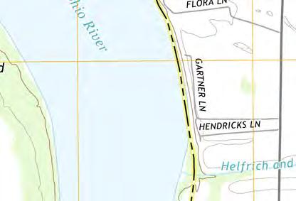
6 AECOM CCR Certification: Initial Inflow Design Flood Control System Plan for the Ash Pond at the A.B. Brown Generating Station 1-1 Introduction 1 Introduction 1.1 Purpose of This Report The purpose of the Initial Inflow Design Flood Control System Plan (Inflow Flood Control Plan) is to document that the requirements specified in 4 Code of Federal Regulations (CFR) have been met to support the certification required under each of the applicable regulatory provisions for the A.B. Brown Generating Station (Brown) Ash Pond. The Ash Pond is an existing coal combustion residuals (CCR) surface impoundment as defined by 4 CFR The CCR Rule requires that the Inflow Flood Control Plan for an existing CCR surface impoundment be prepared by October 17, 216. The Brown station has an interconnected existing CCR surface impoundment, the Ash Pond, which consists of a lower pool and an upper pool. The following table summarizes the documentation required within the CCR Rule and the sections that specifically respond to those requirements of this plan. Table 1-1 CCR Rule Cross Reference Table Report Section Title CCR Rule Reference 4.1 Inflow Analysis (a)(1) 4.2 Outflow Analysis (a)(2) 4.3 Inflow Design Flood (a)(3) 4.4 Discharge handled in accordance with (b) Analyses completed for the hydrologic and hydraulic assessments of the Ash Pond are described in this report. Data and analyses results in the following sections are based on spillway design information shown on design drawings, topographic surveys, information about operational and maintenance procedures provided by Southern Indiana Gas & Electric Company, dba Vectren Power Supply, Inc. (SIGECO), and limited field measurements collected by AECOM. The analysis approach and results of the hydrologic and hydraulic analyses presented in the following sections were used by AECOM to confirm that the Ash Pond meets the hydrologic and hydraulic capacity requirements of the rules referenced above for CCR surface impoundments. 1.2 Brief Description of Impoundment The Brown station is a coal-fired power plant located approximately 1 miles east of Mount Vernon in Posey County, Indiana and is owned and operated by SIGECO. The station is situated just west of the Vanderburgh- Posey County line and north of the Ohio River with the Ash Pond positioned on the east side of the generating station. October 13, 216
7 AECOM CCR Certification: Initial Inflow Design Flood Control System Plan for the Ash Pond at the A.B. Brown Generating Station 1-2 Introduction The Ash Pond was commissioned in An earthen dam was constructed across an existing valley to create the impoundment. In 23, a second dam was constructed east of the original dam and further up the valley to increase the storage capacity. This temporarily created an upper pond and a lower pond. The upper and lower ponds were operated separately until 216 when the upper dam was decommissioned. A 1 wide breach was installed in the upper embankment and the normal pool elevation was lowered. Currently, the upper pool and the lower pool act as one CCR unit referred to as the Ash Pond, which has a surface area of approximately 159 acres. The lower pool dam embankment is approximately 1,54 feet long, 3 feet high, and has 3 to 1 (horizontal to vertical) side slopes covered with grassy vegetation. The embankment crest elevation is 45.9 feet 1 and has a crest width of 2 feet. An earthen buttress was constructed against the outboard slope of the dam. The buttress crest extends the length of the dam, is up to 2 feet wide and varies in elevation from 442. feet to 432. feet. The operating elevation of the pool fluctuates from 439. feet to 444. feet. However, the pool normally operates at an elevation of feet. The surface area of the lower pool impoundment is approximately 57 acres. The surface area of the upper pool impoundment is approximately 12 acres and has a normal operating level of 45 feet. A Site Location Map showing the area surrounding the station is included as Figure 1 of Appendix A. Figure 2 in Appendix A presents the Brown Site Map Inflow from Plant Operations and Stormwater Runoff The Ash Pond impoundment is operated as a zero-discharge facility during normal operating conditions. It receives and impounds sluiced ash from the plant and also recirculates water back to the plant for other necessary processes. Bottom Ash and intermittently Fly Ash are sluiced from the plant into the west side of the upper pool at a combined rate of 9.8 cubic feet per second. The lower pool receives other process flows from the plant at a combined rate of 3.6 cfs. Water is recirculated back to the plant from the lower pool pump station at a variable rate of up to 14. cfs. The Ash Pond is operated such that the outflow to the plant is larger than the inflow from plant processes. Therefore, there is zero-discharge from the Ash Pond outlet devices during normal operating conditions. In addition to rain that fall directly into the ponds, there are upstream areas that contribute runoff to the impoundments. Approximately 63.5 acres drain to the upper pool from upstream areas. The lower pool receives runoff from approximately 19.7 acres upstream as well as the discharged runoff from the upper pool Outlet Structures The upper pool has two outlet devices that are located at the southern end of the embankment. The primary outlet device is a 66-inch diameter RCP drop inlet that is lined with a 63-inch diameter HDPE pipe that has an invert elevation of 45. feet. The drop inlet connects to a 3-inch diameter RCP pipe lined with a 26-inch HDPE pipe that discharges into the lower pool. The secondary outlet device is a 1 wide flat bottom trapezoidal breach with 5 to 1 (horizontal to vertical) side slopes and an invert elevation of 455. feet. The total length of the breach is approximately 32 feet. The upper reach of the channel has a slope of 1.8% for 217 feet while the lower reach has an 8.2% slope over 85 feet. The channel discharges to the lower pool at the approximate elevation of 444. feet. Class II riprap, which has a median diameter of approximately 15 inches, lines the channel to prevent erosion. 1 Unless otherwise noted, all elevations in this report are in the NAVD88 datum. October 13, 216
8 AECOM CCR Certification: Initial Inflow Design Flood Control System Plan for the Ash Pond at the A.B. Brown Generating Station 1-3 Introduction The lower pool has five outlet devices. The first outlet is the Ash Pond Discharge Line. It consists of a 1,5 gallons per minute (gpm) pump which discharges into a 12-inch HDPE pipe that goes to a chemical precipitation treatment system prior to mixing with other plant water and going to an NPDES permitted outfall. Under normal conditions, the line discharges.6 cfs to the treatment system. The second and third outlet devices are two sets of pumps at the lower ash pond pump station: a Low Pressure Recirculation System and a High Pressure Recirculation System. The Low Pressure Recirculation System mainly supplies water to the bottom ash and fly ash handling systems. This system is comprised of three pumps that are rated for 2,75 gpm each. All three pumps discharge into individual 8-inch diameter carbon steel pipes before combining into a common header and proceeding as a 2-inch diameter carbon steel pipeline to the plant. Typically, two pumps operate at a time. Under normal conditions, the pumps recirculate 11. cfs back to the plant. The High Pressure Recirculation System supplies water to the scrubber at various locations. This system is comprised of two high pressure pumps that are rated for 2,1 gpm each. Both pumps discharge into individual 8-inch diameter carbon steel pipes before combining into a common header and proceeding as a 1-inch diameter carbon steel pipeline to the plant. Typically, one pump operates at a time. Under normal conditions, the pump recirculates 2.4 cfs back to the plant. Under normal conditions (both systems in operation) two low pressure pumps and one high pressure pump are in use. The fourth outlet device is the Principal Spillway located in the center of the dam embankment and has a gooseneck inlet structure with a 36-inch RCP drop inlet that acts as an overflow weir at elevation 444. feet. The drop inlet connects to a 36-inch RCP pipe that discharges to a tributary at the toe of the embankment. The fifth outlet device is the Emergency Spillway, a 3 foot wide trapezoidal channel with 5 to 1 (horizontal to vertical) side slopes and an upstream invert elevation of 447. feet. The upper reach of the spillway channel has a slope of.22% for 115 feet before the channel slope steepens down the backside of the embankment and outlets to a tributary at the toe of the slope. The channel is lined with Class II rip-rap. October 13, 216
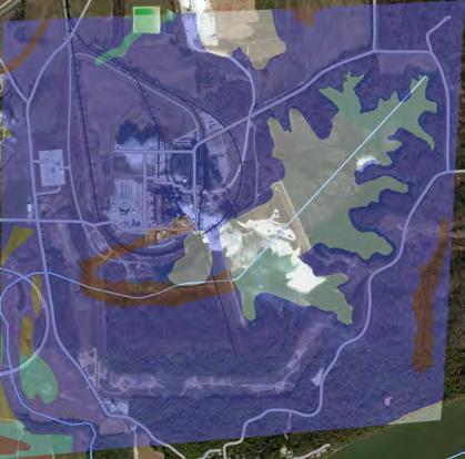
9 AECOM CCR Certification: Initial Inflow Design Flood Control System Plan for the Ash Pond at the A.B. Brown Generating Station 2-1 Hydrologic Analysis 2 Hydrologic Analysis 2.1 Design Storm The Ash Pond has been categorized as a Significant hazard potential CCR impoundment, which indicates that the inflow design flood is the 1,-year return frequency design storm event. The full analysis for this classification determination is included in the CCR Certification: Initial Hazard Potential Classification for the Ash Pond at the A.B. Brown Generating Station. 2.2 Rainfall Data The rainfall information used in the analysis was based on the National Oceanic and Atmospheric Administration (NOAA) Atlas 14, Volume 2, Version 3 which provides rainfall data for storm events with average recurrence intervals ranging from 1 to 1, years and durations ranging from 5 minutes to 6 days. The design storm rainfall depth, obtained from the NOAA website, is 1. inches for the 1,-year, 24-hour storm. The Indiana Huff Third Quartile rainfall distribution used by AECOM is appropriate to use for storms up to the 1,-year, 24- hour flood at the project site. 2.3 Runoff Computations The drainage areas for the Ash Pond were determined using a computer-aided design (CAD) analysis of topographic surveys completed in 214. In addition to rain that falls directly into the pond, there are upstream areas that contribute runoff to the impoundments. Approximately 63.5 acres drain to the upper pool from upstream areas. When the upstream area is added to the 12 acres within the embankments of the impoundment, the total drainage area of the upper pool is acres. The lower pool receives direct runoff from approximately 19.7 acres upstream and 57.2 acres within the embankments of the impoundment. Because the upper pool discharges into the lower pool, the total drainage area to the lower pool is acres. See Figure 3 in Appendix A for the Drainage Area Maps. Runoff was calculated using the SCS Curve Number Method, where curve numbers (CN) were assigned to each subcatchment based on the type of land cover and soil type present. Using the USDA Natural Resources Conservation Service (NRCS) Web Soil Survey, the soil type of the site was determined to be hydrologic soil group C. CN values for the land cover were selected from the CN Table available in HydroCAD. This data was obtained from the SCS NRCS Technical Release-55 (TR-55) publication. Ash, 5%-75% Grass Cover, and Water Surface land covers that are located on site were determined to have a CN value of 98, 79, and 98 respectively. A composite CN was calculated for each subcatchment area by summing the products of each CN multiplied by its percentage of the total area. The time of concentration is commonly defined as the time required for runoff to travel from the most hydrologically distant point to the point of collection. Calculations for the time of concentration for each subwatershed were performed in HydroCAD and are included in Appendix B. Stormwater runoff from the 1-year event into the upper pool has an inflow of cfs and inflow volume of acre-feet. When added to the process flow from the plant, the upper pool has a total inflow of cfs and October 13, 216
10 AECOM CCR Certification: Initial Inflow Design Flood Control System Plan for the Ash Pond at the A.B. Brown Generating Station 2-2 Hydrologic Analysis 2.9 acre-feet. Stormwater runoff into the lower pool (not including the discharged runoff from the upper pool) has a peak inflow of 64.8 cfs and total inflow volume of 57.5 acre-feet. Refer to Appendix B for HydroCAD results. October 13, 216
11 AECOM CCR Certification: Initial Inflow Design Flood Control System Plan for the Ash Pond at the A.B. Brown Generating Station 3-1 Hydraulic Analysis 3 Hydraulic Analyses 3.1 Process Flows The Ash Pond impoundment is operated as a zero-discharge facility during normal operating conditions. The upper pool receives process flow from the plant at a rate of 9.8 cfs. The lower pool receives process flow from the plant at a rate of 3.6 cfs as well as recirculates water back to the plant for other necessary processes at a rate of 14. cfs. The Ash Pond is operated such that the recirculation back to the plant is larger than the inflow from plant processes. Therefore, there is zero-discharge from the Ash Pond outlet devices during normal operating conditions. 3.2 Storage Capacity The storage volumes for the Ash Pond were determined using a computer-aided design (CAD) analysis of topographic surveys completed in 214. The volume of storage was calculated by estimating the incremental storage volume present for each 1 foot elevation within the updated topographic surface supplied by SIGECO representatives. The incremental storage volume was then used to calculate a cumulative storage volume and was input into HydroCAD. The volume of storage within the upper pool from normal pool elevation of 45. feet to the top of embankment elevation of 464. feet is acre-feet. Although the lower pool normally operates at an elevation of feet, the water surface level can fluctuate. Therefore, the maximum operating level of 444. feet was used as the starting water surface elevation during the hydraulic analysis. The volume of storage within the lower pool from the starting water surface elevation of 444. feet to the top of embankment elevation of 45.9 feet is acre-feet. Refer to Appendix B for further storage volume details. 3.3 Discharge Analysis A hydraulic model was created in HydroCAD 1. to assess the capacity of the pond to store and convey the storm flows. HydroCAD has the capability to evaluate each pool within the network, to respond to variable tailwater, pumping rates, permit flow loops, and reversing flows. HydroCAD routing calculations reevaluate the pond s discharge capability at each time increment, making the program an efficient and dynamic tool for this evaluation. The analyzed scenario assumes a starting water surface elevation at the following invert elevations of each pool. The upper pool water surface elevation is 45. feet, and the lower pool is 444. feet. Therefore, the facility does not cause a discharge of pollutants into waters of the United States that is in violation of the requirements of the NPDES under section 42 of the Clean Water Act. October 13, 216
12 AECOM CCR Certification: Initial Inflow Design Flood Control System Plan for the Ash Pond at the A.B. Brown Generating Station 4-1 Results 4 Results The hydrologic and hydraulic conditions of Ash Pond were modeled with the peak discharge of the 1,-year storm event and the current process flow from the plant. Regulatory Citation: 4 CFR (a); - The owner or operator of an existing or new CCR surface impoundment or any lateral expansion of a CCR of a CCR surface impoundment must design, construct, operate, and maintain an inflow design flood control system as specified in paragraphs (a)(1) and (2) of this section. 4.1 Inflow Analysis Regulatory Citation: 4 CFR (a); (1) The inflow design flood control system must adequately manage flow into the CCR unit during and following the peak discharge of the inflows design flood specified in paragraph (3). Background and Assessment Runoff to the impoundment is added to the process flow from the plant to produce the total inflow to the Ash Pond. Using the HydroCAD model, the total inflow was stored and routed through the outlet devices of the Ash Pond to determine the peak water surface elevations. Table 4-1 summarizes the water surface elevations of the Ash Pond prior to and after the inflow design flood. Table Summary of Hydrologic and Hydraulic Analysis 1,-Year, 24-Hour Storm CCR Unit Beginning WSE 1 Peak WSE Top of Embankment Elevation Freeboard Above Peak WSE Upper Pool Lower Pool Notes: 1 WSE = Water Surface Elevation used for hydraulic analysis Conclusion and Recommendation No modifications are necessary or recommended to this unit for compliance with the CCR Rule. As there is adequate storage within the Ash Pond to manage the inflow design flood as well as the process flow from the plant, there is no anticipated overtopping of the Ash Pond embankment, which meets the requirements in (a)(1). October 13, 216
13 AECOM CCR Certification: Initial Inflow Design Flood Control System Plan for the Ash Pond at the A.B. Brown Generating Station 4-2 Results 4.2 Outflow Analysis Regulatory Citation: 4 CFR (a); (2) The inflow design flood control system must adequately manage flow from the CCR unit to collect and control the peak discharge resulting from the inflow design flood specified in paragraph (3) of this section. Background and Assessment Runoff to the impoundment is added to the process flow from the plant to produce the total inflow to the Ash Pond. Using the HydroCAD model, the total inflow was stored and routed through the outlet devices of the Ash Pond to determine the peak flowrate and velocity through the outlet devices. Table 4-2 summarizes the peak flowrates and velocities through each of the outlet devices. Table Summary of Outlet Devices 1,-Year, 24-Hour Storm Invert Elevation Peak Flowrate Velocity at Peak Flowrate Outlet Device Type and Size (fps) Upper Pool Primary Outlet 63 HDPE drop inlet Upper Pool Secondary Outlet Lower Pool Ash Pond Discharge Line Lower Pool Low Pressure Recirculation System Lower Pool High Pressure Recirculation System Lower Pool Principal Spillway Lower Pool Emergency Spillway 1 wide trapezoidal breach 1 1,5 gpm Pump 3 2,75 gpm Pumps 2 2,1 gpm Pumps 36 RCP drop inlet with gooseneck 3 wide trapezoidal channel NA.6 NA NA 11. NA NA 2.4 NA Conclusion and Recommendation No modifications are necessary or recommended to this unit for compliance with the CCR Rule. As the Ash Pond outlet devices manage the discharge of the inflow design flood and the process flow from the plant without the peak water surface elevation overtopping the Ash Pond embankment, the pond meets the requirements in (a)(2). October 13, 216
14 AECOM CCR Certification: Initial Inflow Design Flood Control System Plan for the Ash Pond at the A.B. Brown Generating Station 4-3 Results 4.3 Inflow Design Flood Regulatory Citation: 4 CFR (a); (3) The inflow design flood is: - (i) For a high hazard potential CCR surface impoundment, as determined under (a)(2), the probable maximum flood; - (ii) For a significant hazard potential CCR surface impoundment, as determined under (a)(2), the 1,-year flood; - (iii) For a low hazard potential CCR surface impoundment, as determined under (a)(2), the 1- year flood; or - (iv) For an incised CCR surface impoundment, the 25-year flood. Background and Assessment The calculations for the inflow design flood are based on the hazard potential given to the impoundment. The different classifications of the impoundment hazard potential are high, significant, and low. Conclusion and Recommendation As the impoundment was given a significant hazard potential, the 1, year design storm was utilized in the analysis, which meets the requirements in (a)(3). 4.4 Discharge Regulatory Citation: 4 CFR (b); - Discharge from the CCR unit must be handled in accordance with the surface water requirements under: Background and Assessment The primary discharge from the pond flows through a chemical precipitation treatment system prior to mixing with other plant water and discharging to an NPDES permitted outfall. The emergency discharge from the Ash Pond outlet devices enters a tributary via a permitted NPDES outfall that leads to the Ohio River. The discharge must meet the requirements of the NDPES permit under section 42 of the Clean Water Act to meet the CCR rule. Conclusion and Recommendation No modifications are necessary or recommended to this unit for compliance with the CCR Rule. Runoff discharges from the site through a permitted NPDES outfall to an unnamed tributary which travels west for approximately.5 miles before turning south for approximately one mile and discharging into the Ohio River. As per the current NPDES permit, all discharged water is tested for pollutants to meet the minimum regulatory requirements of the permit, and thereby meets the requirements in (b). October 13, 216
15 AECOM CCR Certification: Initial Inflow Design Flood Control System Plan for the Ash Pond at the A.B. Brown Generating Station 5-1 Conclusions 5 Conclusions The Inflow Flood Control Plan of the Ash Pond adequately manages flow into the CCR unit during and following the peak discharge of the 1,-year frequency storm event inflow design flood. The inflow design flood control system of the Ash Pond adequately manages flow from the CCR unit to collect and control the peak discharge resulting from the 1,-year frequency storm event inflow design flood. Therefore, the Ash Pond meets the requirements for certification. The contents of this report, specifically Section 1 through Section 4, represent the Initial Inflow Design Flood Control System Plan for this site. October 13, 216


16
17 AECOM CCR Certification: Initial Inflow Design Flood Control System Plan for the Ash Pond at the A.B. Brown Generating Station 7-1 Limitations 7 Limitations Background information, design basis, and other data have been furnished to AECOM by SIGECO, which AECOM has used in preparing this report. AECOM has relied on this information as furnished, and is not responsible for the accuracy of this information. Our recommendations are based on available information from previous and current investigations. These recommendations may be updated as future investigations are performed. The conclusions presented in this report are intended only for the purpose, site location, and project indicated. The recommendations presented in this report should not be used for other projects or purposes. Conclusions or recommendations made from these data by others are their responsibility. The conclusions and recommendations are based on AECOM s understanding of current plant operations, maintenance, stormwater handling, and ash handling procedures at the station, as provided by SIGECO. Changes in any of these operations or procedures may invalidate the findings in this report until AECOM has had the opportunity to review the findings, and revise the report if necessary. This hydrologic and hydraulic analysis was performed in accordance with the standard of care commonly used as state-of-practice in our profession. Specifically, our services have been performed in accordance with accepted principles and practices of the geological and geotechnical engineering profession. The conclusions presented in this report are professional opinions based on the indicated project criteria and data available at the time this report was prepared. Our services were provided in a manner consistent with the level of care and skill ordinarily exercised by other professional consultants under similar circumstances. No other representation is intended. While the CCR unit adequately manages the inflow design flood, SIGECO must perform routine maintenance on the CCR unit to continually manage flood events without failure. Outlet devices should be cleared of debris that could block or damage the device. Pipes and intake structures should be monitored and repaired if deterioration or deformation occurs. All grass lined slopes should be examined for erosion and repaired if damaged. Rip-rap lined channels should be inspected for stones that have shifted or bare spots that have formed. Replace rip-rap as needed. October 13, 216
18 AECOM CCR Certification: Initial Inflow Design Flood Control System Plan for the Ash Pond at the A.B. Brown Generating Station Appendix A Figures Figure 1 Location Map Figure 2 Site Map Figure 3 Drainage Area Map October 13, 216


19 94 Amberglen Boulevard Austin, TX (phone) (fax) SOUTHERN INDIANA GAS AND ELECTRIC COMPANY dba VECTREN POWER SUPPLY, INC. One Vectren Square Evansville, IN (phone) A.B. BROWN GENERATING STATION MT. VERNON, IN CCR CERTIFICATION ASH POND ISSUED FOR CERTIFICATION UPPER ASH POOL ISSUED FOR BIDDING DATE BY ISSUED FOR CONSTRUCTION DATE BY A.B. BROWN GENERATING STATION REVISIONS NO. DESCRIPTION DATE LOWER ASH POOL AECOM PROJECT NO: DRAWN BY: DESIGNED BY: CHECKED BY: DATE CREATED: PLOT DATE: SCALE: ACAD VER: MJC MJC TLE 4/22/216 AS SHOWN 214 SHEET TITLE LOCATION MAP SCALE IN FEET
 A.B. BROWN GENERATING STATION MT.")
20 94 Amberglen Boulevard Austin, TX (phone) (fax) SOUTHERN INDIANA GAS AND ELECTRIC COMPANY dba VECTREN POWER SUPPLY, INC. One Vectren Square Evansville, IN (phone) A.B. BROWN GENERATING STATION MT. VERNON, IN CCR CERTIFICATION ASH POND GENERATING STATION UPPER ASH POOL ISSUED FOR CERTIFICATION ISSUED FOR BIDDING DATE BY LOWER ASH POOL PRIMARY OUTLET DEVICE 63" HDPE DROP INLET ISSUED FOR CONSTRUCTION REVISIONS DATE BY PUMP STATION SECONDARY OUTLET DEVICE 1' WIDE TRAPEZOIDAL BREACH NO. DESCRIPTION DATE PRIMARY OUTLET DEVICE 36" HDPE DROP INLET TRIBUTARY TO THE OHIO RIVER SECONDARY OUTLET DEVICE 3' WIDE TRAPEZOIDAL EMERGENCY SPILLWAY AECOM PROJECT NO: DRAWN BY: DESIGNED BY: CHECKED BY: DATE CREATED: PLOT DATE: SCALE: ACAD VER: SHEET TITLE MJC MJC TLE 4/22/216 AS SHOWN SITE MAP SCALE IN FEET OHIO RIVER
 A.B. BROWN GENERATING STATION MT.")
21 94 Amberglen Boulevard Austin, TX (phone) (fax) UPPER ASH POOL DRAINAGE AREA = ACRES VEGETATIVE COVER AREA = 73.9 SOUTHERN INDIANA GAS AND ELECTRIC COMPANY dba VECTREN POWER SUPPLY, INC. One Vectren Square Evansville, IN (phone) A.B. BROWN GENERATING STATION MT. VERNON, IN CCR CERTIFICATION ASH POND ISSUED FOR CERTIFICATION ISSUED FOR BIDDING DATE BY ISSUED FOR CONSTRUCTION DATE BY REVISIONS NO. DESCRIPTION DATE LOWER ASH POOL DRAINAGE AREA = ACRES VEGETATIVE COVER AREA = 27.1 ACRES AECOM PROJECT NO: DRAWN BY: MJC DESIGNED BY: MJC CHECKED BY: TLE DATE CREATED: PLOT DATE: 4/22/216 SCALE: AS SHOWN ACAD VER: 214 SHEET TITLE DRAINAGE AREA MAP SCALE IN FEET
22 AECOM CCR Certification: Initial Inflow Design Flood Control System Plan for the Ash Pond at the A.B. Brown Generating Station Appendix B Hydrologic and Hydraulic Calculations NOAA Precipitation Data Soils Data Water Balance HydroCAD Output October 13, 216
23 AECOM Initial Inflow Design Flood Control System Plan For the Ash Pond System at the A.B. Brown Generating Station NOAA Precipitation Data Attorney Client Privileged October 216

24 Precipitation Frequency Data Server Page 1 of 4 NOAA Atlas 14, Volume 2, Version 3 Location name: Mount Vernon, Indiana, US* Latitude: , Longitude: Elevation: 44 ft* * source: Google Maps POINT PRECIPITATION FREQUENCY ESTIMATES G.M. Bonnin, D. Martin, B. Lin, T. Parzybok, M.Yekta, and D. Riley NOAA, National Weather Service, Silver Spring, Maryland PF_tabular PF_graphical Maps_&_aerials Duration 5-min 1-min 15-min 3-min 6-min 2-hr 3-hr 6-hr 12-hr 24-hr 2-day 3-day 4-day 7-day 1-day 2-day 3-day 45-day 6-day PF tabular PDS-based point precipitation frequency estimates with 9% confidence intervals (in inches) 1 Average recurrence interval (years) ( ).612 ( ).75 ( ).993 ( ) 1.21 ( ) 1.46 ( ) 1.57 ( ) 1.93 ( ) 2.28 ( ) 2.74 ( ) 3.25 ( ) 3.46 ( ) 3.67 ( ) 4.27 ( ) 4.81 ( ) 6.63 ( ) 8.17 ( ) 1.2 ( ) 12.2 ( ).465 ( ).726 ( ).888 ( ) 1.19 ( ) 1.46 ( ) 1.77 ( ) 1.9 ( ) 2.33 ( ) 2.75 ( ) 3.29 ( ) 3.91 ( ) 4.15 ( ) 4.39 ( ) 5.11 ( ) 5.75 ( ) 7.87 ( ) 9.65 ( ) 12. ( ) 14.3 ( ).551 ( ).856 ( ) 1.5 ( ) 1.44 ( ) 1.81 ( ) 2.21 ( ) 2.38 ( ) 2.9 ( ) 3.41 ( ) 4.1 ( ) 4.86 ( ) 5.15 ( ) 5.44 ( ) 6.31 ( ) 7.11 ( ) 9.43 ( ) 11.4 ( ) 14.1 ( ) 16.6 ( ).62 ( ).956 ( ) 1.18 ( ) 1.63 ( ) 2.8 ( ) 2.56 ( ) 2.76 ( ) 3.37 ( ) 3.96 ( ) 4.75 ( ) 5.65 ( ) 5.98 ( ) 6.32 ( ) 7.32 ( ) 8.23 ( ) 1.7 ( ) 12.8 ( ) 15.7 ( ) 18.4 ( ).77 ( ) 1.8 ( ) 1.34 ( ) 1.89 ( ) 2.45 ( ) 3.5 ( ) 3.31 (3.-3.6) 4.4 ( ) 4.72 ( ) 5.65 ( ) 6.77 ( ) 7.19 ( ) 7.61 ( ) 8.78 ( ) 9.85 ( ) 12.4 ( ) 14.7 ( ) 17.8 ( ) 2.8 ( ).776 ( ) 1.18 ( ) 1.46 ( ) 2.8 ( ) 2.74 ( ) 3.44 ( ) 3.75 ( ) 4.59 ( ) 5.34 ( ) 6.39 ( ) 7.7 ( ) 8.19 ( ) 8.68 ( ) 1. ( ) 11.2 ( ) 13.8 ( ) 16.2 ( ) 19.5 ( ) 22.5 ( ).843 ( ) 1.27 ( ) 1.58 ( ) 2.28 ( ) 3.5 ( ) 3.84 ( ) 4.21 ( ) 5.17 ( ) 6. ( ) 7.16 ( ) 8.7 ( ) 9.27 ( ) 9.84 ( ) 11.3 ( ) 12.6 ( ) 15.2 ( ) 17.7 ( ) 21.2 ( ) 24.3 ( ) 1 Precipitation frequency (PF) estimates in this table are based on frequency analysis of partial duration series (PDS)..914 ( ) 1.37 ( ) 1.7 ( ) 2.48 ( ) 3.36 ( ) 4.26 ( ) 4.7 ( ) 5.78 ( ) 6.7 ( ) 7.97 ( ) 9.76 ( ) 1.4 ( ) 11.1 ( ) 12.7 ( ) 14.2 ( ) 16.7 ( ) 19.2 ( ) 22.8 ( ) 26. ( ) 1.1 ( ) 1.48 ( ) 1.85 ( ) 2.74 ( ) 3.79 ( ) 4.85 ( ) 5.39 ( ) 6.66 ( ) 7.68 ( ) 9.1 ( ) 11.3 ( ) 12.1 ( ) 12.9 ( ) 14.8 ( ) 16.4 ( ) 18.7 ( ) 21.3 ( ) 25.1 ( ) 28.2 ( ) 1.8 ( ) 1.57 ( ) 1.96 ( ) 2.94 ( ) 4.14 ( ) 5.31 ( ) 5.94 ( ) 7.37 ( ) 8.47 ( ) 1. ( ) 12.5 ( ) 13.5 ( ) 14.4 ( ) 16.4 ( ) 18.2 ( ) 2.2 ( ) 22.9 ( ) 26.8 ( ) 29.9 ( ) Numbers in parenthesis are PF estimates at lower and upper bounds of the 9% confidence interval. The probability that precipitation frequency estimates (for a given duration and average recurrence interval) will be greater than the upper bound (or less than the lower bound) is 5%. Estimates at upper bounds are not checked against probable maximum precipitation (PMP) estimates and may be higher than currently valid PMP values. Please refer to NOAA Atlas 14 document for more information. Back to Top PF graphical 6/3/216


25 Precipitation Frequency Data Server Page 2 of 4 6/3/216 Back to Top Maps & aerials Small scale terrain 5 km Map data Report 216 a map Google error


26 Precipitation Frequency Data Server Page 3 of 4 6/3/216 Large scale terrain 2 km Map data Report 216 a map Google error Large scale map 2 km Map data Report 216 a map Google error Large scale aerial 2 km Imagery 216 Report TerraMetrics a map error Back to Top US Department of Commerce National Oceanic and Atmospheric Administration National Weather Service National Water Center 1325 East West Highway Silver Spring, MD 291
27 Precipitation Frequency Data Server Page 4 of 4 6/3/216 Questions?: HDSC.Questions@noaa.gov Disclaimer
28 AECOM Initial Inflow Design Flood Control System Plan For the Ash Pond System at the A.B. Brown Generating Station Soils Data Attorney Client Privileged October 216

29
30
31
32
33
34 AECOM Initial Inflow Design Flood Control System Plan For the Ash Pond System at the A.B. Brown Generating Station Water Balance Attorney Client Privileged October 216
35 e i d g + n e (812) THREE I DESIGN JOB NUMBER: 2218A F-225.4
36 AECOM Initial Inflow Design Flood Control System Plan For the Ash Pond System at the A.B. Brown Generating Station HydroCAD Output Report Attorney Client Privileged October 216

37 2S Drainage Area1 3S Drainage Area2 4R 6R Breach - Upper Reach 1P 1S Breach-Lower Reach Upper Pond Ponded Area-South 4S Ponded Area 5R Discharge Creek 8R 2P Discharge Ditch 2R Spillway - Lower Reach 7R Lower Pond 3R Spillway - Upper Reach Spillway - Middle Reach Subcat Reach Pond Link Routing Diagram for Brown - CCR Certification - Proposed 1ft Breach-Normal pool 441.5,
38 Brown - CCR Certification - Proposed 1ft Breach-Normal pool Page 2 Area (acres) CN Description (subcatchment-numbers) Area Listing (all nodes) % Grass cover, Fair, HSG C (2S, 3S) Ash (2S, 3S) Water Surface, % imp, HSG C (1S) Water Surface, HSG C (2S, 4S) TOTAL AREA
39 Brown - CCR Certification - Proposed 1ft Breach-Normal pool Page 3 Area (acres) Soil Group Subcatchment Numbers. HSG A. HSG B HSG C 1S, 2S, 3S, 4S. HSG D Other 2S, 3S TOTAL AREA Soil Listing (all nodes)
40 Brown - CCR Certification - Proposed 1ft Breach-Normal pool Page 4 HSG-A (acres) HSG-B (acres) HSG-C (acres) Ground Covers (all nodes) HSG-D (acres) Other (acres) Total (acres) Ground Cover Subcatchment Numbers % Grass cover, Fair 2S, 3S Ash 2S, 3S Water Surface 2S, 4S Water Surface, % imp 1S TOTAL AREA
41 Brown - CCR Certification - Proposed 1ft Breach-Normal pool Page 5 Line# Node Number In-Invert Out-Invert Pipe Listing (all nodes) Length Slope (ft/ft) n Diam/Width (inches) Height (inches) Inside-Fill (inches) 1 1P P
42 Brown - CCR Certification - Proposed 1ft Breach-Normal pool Page 6 Line# Node Number Notes Notes Listing (all nodes) 1 2S see autocad file Brown-Ash-Pond-Hydro.dwg for lenghts, slopes for Tc 2 3S see autocad file Brown-Ash-Pond-Hydro.dwg for lenghts, slopes for Tc 3 1P Elevations of outlet taken from ATC Hydraulic analyses and decommising report dated Feb 17, Outlet sizes from ATC Report are shown in Outside Diameter. Inside diameter for 63" HDPE DR 21pipe is 56.6". Inside Diameter for 26" HDPE DR 17 pipe is 22.8". 5 2P Elevations of outlet taken from ATC Hydraulic analyses and decommising report dated Feb 17, 216
43 Page 7 Time span=.-1. hrs, dt=.1 hrs, 11 points Runoff by SCS TR-2 method, UH=SCS, Weighted-CN Reach routing by Dyn-Stor-Ind method - Pond routing by Dyn-Stor-Ind method Subcatchment 1S: Ponded Area-South Subcatchment 2S: Drainage Area1 Subcatchment 3S: Drainage Area2 Subcatchment 4S: Ponded Area Runoff Area=5.93 ac.% Impervious Runoff Depth=9.76" Tc=. min CN=98 Runoff=5.23 cfs af Runoff Area= ac 53.68% Impervious Runoff Depth=8.66" Flow Length=3,275' Tc=46.4 min CN=89 Runoff= cfs af Runoff Area=41.41 ac 34.56% Impervious Runoff Depth=8.28" Flow Length=2,725' Tc=44.6 min CN=86 Runoff=34.9 cfs af Runoff Area=35.56 ac 1.% Impervious Runoff Depth=9.76" Tc=. min CN=98 Runoff=31.39 cfs af Reach 2R: Spillway - Lower Reach Avg. Flow Depth=.' Max Vel=. fps Inflow=. cfs. af n=.83 L=41.3' S=.2814 '/' Capacity=2, cfs Outflow=. cfs. af Reach 3R: Spillway - Upper Reach Avg. Flow Depth=.' Max Vel=. fps Inflow=. cfs. af n=.3 L=115.' S=.22 '/' Capacity=1, cfs Outflow=. cfs. af Reach 4R: Breach-Lower Reach Avg. Flow Depth=1.16' Max Vel=4.6 fps Inflow=84.34 cfs af n=.83 L=85.' S=.835 '/' Capacity=1, cfs Outflow=84.34 cfs af Reach 5R: Discharge Creek Avg. Flow Depth=.74' Max Vel=5.84 fps Inflow=38.78 cfs af n=.4 L=8.' S=.55 '/' Capacity=2, cfs Outflow=38.78 cfs af Reach 6R: Breach - Upper Reach Avg. Flow Depth=1.71' Max Vel=2.65 fps Inflow=84.34 cfs af n=.83 L=217.' S=.18 '/' Capacity= cfs Outflow=84.34 cfs af Reach 7R: Spillway - Middle Reach Avg. Flow Depth=.' Max Vel=. fps Inflow=. cfs. af n=.83 L=18.' S=.1983 '/' Capacity=2, cfs Outflow=. cfs. af Reach 8R: Discharge Ditch Avg. Flow Depth=.' Max Vel=. fps Inflow=. cfs. af n=.83 L=42.5' S=.25 '/' Capacity=2,46.7 cfs Outflow=. cfs. af Pond 1P: Upper Pond Peak Elev=457.63' Storage= af Inflow=149.5 cfs af Primary=34.93 cfs af Secondary=84.34 cfs af Outflow= cfs af Pond 2P: Lower Pond Peak Elev=446.78' Storage= af Inflow=17.84 cfs af Primary=38.78 cfs af Secondary=. cfs. af Tertiary=1.38 cfs af Outflow=49.16 cfs af Total Runoff Area = ac Runoff Volume = af Average Runoff Depth = 8.78" 44.11% Pervious = ac 55.89% Impervious = ac
44 Page 8 Summary for Subcatchment 1S: Ponded Area-South [46] Hint: Tc= (Instant runoff peak depends on dt) Runoff = hrs, Volume= af, Depth= 9.76" Runoff by SCS TR-2 method, UH=SCS, Weighted-CN, Time Span=.-1. hrs, dt=.1 hrs Indy Huff 3rd Quartile 24. hrs 1 year storm Indy Huff Rainfall=1." Area (ac) CN Description Water Surface, % imp, HSG C % Pervious Area Tc Length Slope Velocity Capacity Description (min) (ft/ft) (ft/sec). Direct Entry, Subcatchment 1S: Ponded Area-South Hydrograph cfs Indy Huff 3rd Quartile 24. hrs 1 year storm Indy Huff Rainfall=1." Runoff Area=5.93 ac Runoff Volume=4.823 af Runoff Depth=9.76" Tc=. min CN=98 Runoff Flow Time (hours)
45 Page 9 Hydrograph for Subcatchment 1S: Ponded Area-South Time (hours) Precip. (inches) Excess (inches) Runoff Time (hours) Precip. (inches) Excess (inches) Runoff
46 Page 1 Summary for Subcatchment 2S: Drainage Area1 see autocad file Brown-Ash-Pond-Hydro.dwg for lenghts, slopes for Tc Runoff = hrs, Volume= af, Depth= 8.66" Runoff by SCS TR-2 method, UH=SCS, Weighted-CN, Time Span=.-1. hrs, dt=.1 hrs Indy Huff 3rd Quartile 24. hrs 1 year storm Indy Huff Rainfall=1." Area (ac) CN Description % Grass cover, Fair, HSG C Water Surface, HSG C Water Surface, HSG C * Ash Weighted Average % Pervious Area % Impervious Area Tc Length Slope Velocity Capacity Description (min) (ft/ft) (ft/sec) Sheet Flow, Grass: Short n=.15 P2= 3.29" Shallow Concentrated Flow, Grassed Waterway Kv= 15. fps 3.6 2, Shallow Concentrated Flow, Grassed Waterway Kv= 15. fps ,275 Total
47 Page 11 Subcatchment 2S: Drainage Area1 Hydrograph Flow cfs Indy Huff 3rd Quartile 24. hrs 1 year storm Indy Huff Rainfall=1." Runoff Area= ac Runoff Volume= af Runoff Depth=8.66" Flow Length=3,275' Tc=46.4 min CN=89 Runoff Time (hours)
48 Page 12 Hydrograph for Subcatchment 2S: Drainage Area1 Time (hours) Precip. (inches) Excess (inches) Runoff Time (hours) Precip. (inches) Excess (inches) Runoff
49 Page 13 Summary for Subcatchment 3S: Drainage Area2 see autocad file Brown-Ash-Pond-Hydro.dwg for lenghts, slopes for Tc Runoff = hrs, Volume= af, Depth= 8.28" Runoff by SCS TR-2 method, UH=SCS, Weighted-CN, Time Span=.-1. hrs, dt=.1 hrs Indy Huff 3rd Quartile 24. hrs 1 year storm Indy Huff Rainfall=1." Area (ac) CN Description % Grass cover, Fair, HSG C * Ash Weighted Average % Pervious Area % Impervious Area Tc Length Slope Velocity Capacity Description (min) (ft/ft) (ft/sec) Sheet Flow, Sheet Flow Grass: Short n=.15 P2= 3.29" Shallow Concentrated Flow, Grassed Waterway Kv= 15. fps , Shallow Concentrated Flow, Grassed Waterway Kv= 15. fps ,725 Total Subcatchment 3S: Drainage Area2 Hydrograph Flow cfs Time (hours) Indy Huff 3rd Quartile 24. hrs 1 year storm Indy Huff Rainfall=1." Runoff Area=41.41 ac Runoff Volume= af Runoff Depth=8.28" Flow Length=2,725' Tc=44.6 min CN= Runoff
50 Page 14 Hydrograph for Subcatchment 3S: Drainage Area2 Time (hours) Precip. (inches) Excess (inches) Runoff Time (hours) Precip. (inches) Excess (inches) Runoff
CCR Annual Inspection (b) for the Ash Pond at the A.B. Brown Generating Station. Revision 0
 for the Ash Pond at the A.B. Brown Generating Station. Revision 0") Submitted to Southern Indiana Gas & Electric Company dba Vectren Power Supply, Inc. (SIGECO) One Vectren Square Evansville, IN 47708 Submitted by AECOM 9400 Amberglen Boulevard Austin, Texas 78729 257.83
Submitted to Southern Indiana Gas & Electric Company dba Vectren Power Supply, Inc. (SIGECO) One Vectren Square Evansville, IN 47708 Submitted by AECOM 9400 Amberglen Boulevard Austin, Texas 78729 257.83
CCR Certification: Initial Written Post-Closure Plan (d) for the Ash Pond at the A.B. Brown Generating Station. Revision 0
 for the Ash Pond at the A.B. Brown Generating Station. Revision 0") Submitted to Southern Indiana Gas & Electric Company dba Vectren Power Supply, Inc. (SIGECO) One Vectren Square. Evansville, IN 47708 Submitted by AECOM 9400 Amberglen Boulevard Austin, Texas 78729 CCR
Submitted to Southern Indiana Gas & Electric Company dba Vectren Power Supply, Inc. (SIGECO) One Vectren Square. Evansville, IN 47708 Submitted by AECOM 9400 Amberglen Boulevard Austin, Texas 78729 CCR
CCR Annual Inspection (b) for the Ash Pond at the A.B. Brown Generating Station. Revision 0
 for the Ash Pond at the A.B. Brown Generating Station. Revision 0") Submitted to Southern Indiana Gas & Electric Company dba Vectren Power Supply, Inc. (SIGECO) One Vectren Square Evansville, IN 47708 Submitted by AECOM 9400 Amberglen Boulevard Austin, Texas 78729 257.83
Submitted to Southern Indiana Gas & Electric Company dba Vectren Power Supply, Inc. (SIGECO) One Vectren Square Evansville, IN 47708 Submitted by AECOM 9400 Amberglen Boulevard Austin, Texas 78729 257.83
Initial Inflow Design Flood Control System Plan Holding Pond
 Submitted to: Submitted by: Marquette Board of Light and Power AECOM Shiras Steam Plant Marquette, Michigan Marquette, Michigan Project No. 60445171 October 2016 Initial Inflow Design Flood Control System
CCR Certification: Initial Structural Stability Assessment (d)
") Submitted to Southern Indiana Gas & Electric Company dba Vectren Power Supply, Inc. (SIGECO) One Vectren Square Evansville, IN 47708 Submitted by AECOM 9400 Amberglen Boulevard Austin, Texas 78729 CCR
Submitted to Southern Indiana Gas & Electric Company dba Vectren Power Supply, Inc. (SIGECO) One Vectren Square Evansville, IN 47708 Submitted by AECOM 9400 Amberglen Boulevard Austin, Texas 78729 CCR
Inflow Design Flood Control System Plan
 Inflow Design Flood Control System Plan For Compliance with the Coal Combustion Residuals Rule (40 CFR Part 257) Valmont Station - CCR Surface Impoundments Public Service Company of Colorado Denver, Colorado
Run-on and Run-off Control System Plan
 Run-on and Run-off Control System Plan CCR Temporary Storage Pad Lewis and Clark Station Prepared for Montana-Dakota Utilities Co. October 2016 Paul T. Swenson 2016.10.13 18:30:03-05'00' 234 West Century
CCR Certification: Initial Written Post-Closure Plan (d) for the East Ash Pond at the F.B. Culley Generating Station.
 for the East Ash Pond at the F.B. Culley Generating Station.") Submitted to Southern Indiana Gas & Electric Company dba Vectren Power Supply, Inc. (SIGECO) One Vectren Square Evansville, IN 47708 Submitted by 9400 Amberglen Boulevard Austin, Texas 78729 CCR Certification:
Submitted to Southern Indiana Gas & Electric Company dba Vectren Power Supply, Inc. (SIGECO) One Vectren Square Evansville, IN 47708 Submitted by 9400 Amberglen Boulevard Austin, Texas 78729 CCR Certification:
Run-on and Run-off Control System Plan
 Run-on and Run-off Control System Plan J.H. CAMPBELL GENERATING FACILITY DRY ASH LANDFILL RUN-ON AND RUN-OFF CONTROL SYSTEM PLAN West Olive, Michigan Pursuant to 4 CFR 257.81 Submitted To: Consumers Energy
CCR Certification: Initial Inflow Design Flood Control System Plan for the. East Ash Pond. at the. F.B. Culley Generating Station.
 Submitted to Southern Indiana Gas & Electric Company dba Vectren Power Supply, Inc. (SIGECO) One Vectren Square Evansville, IN 4772 Submitted by AECOM 94 Amberglen Boulevard Austin, Texas 78729 October
INFLOW DESIGN FLOOD CONTROL SYSTEM PLAN 40 C.F.R. PART PLANT YATES ASH POND 3 (AP-3) GEORGIA POWER COMPANY
 GEORGIA POWER COMPANY") INFLOW DESIGN FLOOD CONTROL SYSTEM PLAN 40 C.F.R. PART 257.82 PLANT YATES ASH POND 3 (AP-3) GEORGIA POWER COMPANY EPA s Disposal of Coal Combustion Residuals from Electric Utilities Final Rule (40 C.F.R.
INFLOW DESIGN FLOOD CONTROL SYSTEM PLAN 40 C.F.R. PART 257.82 PLANT YATES ASH POND 3 (AP-3) GEORGIA POWER COMPANY EPA s Disposal of Coal Combustion Residuals from Electric Utilities Final Rule (40 C.F.R.
Inflow Design Flood Control System Plan
 Inflow Design Flood Control System Plan Scrubber Ponds Lewis and Clark Station Prepared for Montana-Dakota Utilities Co. October 2016 Paul T. Swenson 2016.10.14 17:54:29-05'00' 234 West Century Avenue
INFLOW DESIGN FLOOD CONTROL SYSTEM PLAN 40 C.F.R. PART PLANT BOWEN ASH POND 1 (AP-1) GEORGIA POWER COMPANY
 GEORGIA POWER COMPANY") INFLOW DESIGN FLOOD CONTROL SYSTEM PLAN 40 C.F.R. PART 257.82 PLANT BOWEN ASH POND 1 (AP-1) GEORGIA POWER COMPANY EPA s Disposal of Coal Combustion Residuals from Electric Utilities Final Rule (40 C.F.R.
INFLOW DESIGN FLOOD CONTROL SYSTEM PLAN 40 C.F.R. PART 257.82 PLANT BOWEN ASH POND 1 (AP-1) GEORGIA POWER COMPANY EPA s Disposal of Coal Combustion Residuals from Electric Utilities Final Rule (40 C.F.R.
INFLOW DESIGN FLOOD CONTROL SYSTEM PLAN PLANT GREENE COUNTY ASH POND ALABMA POWER COMPANY
 INFLOW DESIGN FLOOD CONTROL SYSTEM PLAN PLANT GREENE COUNTY ASH POND ALABMA POWER COMPANY Section 257.82 of EPA s regulations requires the owner or operator of an existing or new CCR surface impoundment
INFLOW DESIGN FLOOD CONTROL SYSTEM PLAN 40 C.F.R. PART PLANT YATES ASH POND B (AP-B ) GEORGIA POWER COMPANY
 GEORGIA POWER COMPANY") INFLOW DESIGN FLOOD CONTROL SYSTEM PLAN 40 C.F.R. PART 257.82 PLANT YATES ASH POND B (AP-B ) GEORGIA POWER COMPANY EPA s Disposal of Coal Combustion Residuals from Electric Utilities Final Rule (40 C.F.R.
INFLOW DESIGN FLOOD CONTROL SYSTEM PLAN 40 C.F.R. PART 257.82 PLANT YATES ASH POND B (AP-B ) GEORGIA POWER COMPANY EPA s Disposal of Coal Combustion Residuals from Electric Utilities Final Rule (40 C.F.R.
CCR Certification: Amended Inflow Design Flood Control System Plan for the. East Ash Pond. at the. F.B. Culley Generating Station.
 Submitted to Southern Indiana Gas & Electric Company dba Vectren Power Supply, Inc. (SIGECO) One Vectren Square Evansville, IN 4772 Submitted by AECOM 94 Amberglen Boulevard Austin, Texas 78729 February
Green Station CCR Surface Impoundment
 Green Station CCR Surface Impoundment Disposal of Coal Combustion Residuals (CCR) from Electric Utilities Final Rule Hydrologic and Hydraulic Capacity Assessment and Initial Inflow Design Flood Control
INFLOW DESIGN FLOOD CONTROL SYSTEM PLAN 40 C.F.R. PART PLANT DANIEL ASH POND B MISSISSIPPI POWER COMPANY
 INFLOW DESIGN FLOOD CONTROL SYSTEM PLAN 40 C.F.R. PART 257.82 PLANT DANIEL ASH POND B MISSISSIPPI POWER COMPANY EPA s Disposal of Coal Combustion Residuals from Electric Utilities Final Rule (40 C.F.R.
INFLOW DESIGN FLOOD CONTROL SYSTEM PLAN PLANT BARRY ASH POND ALABAMA POWER COMPANY
 INFLOW DESIGN FLOOD CONTROL SYSTEM PLAN PLANT BARRY ASH POND ALABAMA POWER COMPANY Section 257.82 of EPA s regulations requires the owner or operator of an existing or new CCR surface impoundment or any
NC2 Ash Disposal Area Run-on and Run-off Control System Plan
 NC2 Ash Disposal Area Run-on and Run-off Control System Plan Omaha Public Power District Nebraska City Station Nebraska City, Nebraska October 17, 2016 OPPD NC2 Ash Disposal Area Run-On and Run-Off Control
INITIAL RUN-ON AND RUN-OFF CONTROL PLAN 40 C.F.R. PART 257
 INITIAL RUN-ON AND RUN-OFF CONTROL PLAN 40 C.F.R. PART 257.81 PLANT BOWEN PRIVATE INDUSTRY SOLID WASTE DISPOSAL FACILITY (ASH LANDFILL) GEORGIA POWER COMPANY EPA s Disposal of Coal Combustion Residuals
INFLOW DESIGN FLOOD CONTROL SYSTEM PLAN PLANT GASTON GYPSUM POND ALABAMA POWER COMPANY
 INFLOW DESIGN FLOOD CONTROL SYSTEM PLAN PLANT GASTON GYPSUM POND ALABAMA POWER COMPANY Section 257.82 of EPA s regulations requires the owner or operator of an existing or new CCR surface impoundment or
North Omaha Ash Landfill Run-on and Run-off Control System Plan
 North Omaha Ash Landfill Run-on and Run-off Control System Plan Omaha Public Power District North Omaha Station Omaha, Nebraska October 17, 216 OPPD North Omaha Ash Landfill Run-On and Run-Off Control
Inflow Design Flood Control System Plan
 Inflow Design Flood Control System Plan For Compliance with the Coal Combustion Residuals Rule (40 CFR Part 257) Cherokee Station - CCR Surface Impoundments Public Service Company of Colorado Denver, Colorado
Inflow Design Flood Control System Plan
 Inflow Design Flood Control System Plan Scrubber Ponds Lewis & Clark Station Prepared for Montana-Dakota Utilities Co. November 2018 234 West Century Avenue Bismarck, ND 58503 701.255.5460 www.barr.com
INFLOW DESIGN FLOOD CONTROL SYSTEM PLAN 40 C.F.R. Part PLANT MCINTOSH ASH POND 1 GEORGIA POWER COMPANY
 INFLOW DESIGN FLOOD CONTROL SYSTEM PLAN 40 C.F.R. Part 257.82 PLANT MCINTOSH ASH POND 1 GEORGIA POWER COMPANY EPA s Disposal of Coal Combustion Residuals from Electric Utilities Final Rule (40 C.F.R. Part
CCR Annual Inspection (b) for the West Ash Pond at the F. B. Culley Generating Station. Revision 0
 for the West Ash Pond at the F. B. Culley Generating Station. Revision 0") Submitted to Southern Indiana Gas & Electric Company dba Vectren Power Supply, Inc. (SIGECO) One Vectren Square Evansville, IN 47708 Submitted by AECOM 9400 Amberglen Boulevard Austin, Texas 78729 257.83
Submitted to Southern Indiana Gas & Electric Company dba Vectren Power Supply, Inc. (SIGECO) One Vectren Square Evansville, IN 47708 Submitted by AECOM 9400 Amberglen Boulevard Austin, Texas 78729 257.83
Watershed size and name: The drainage area is acres. The pond is located within the Ohio River watershed. (2016 Inflow Design Plan)
") A. B. Brown History of Construction 40 CFR 257.73 (c) (i.) (ii.) (iii.) Owner Name: Southern Indiana Gas and Electric Company dba Vectren Power Supply Owner Address: One Vectren Square, PO Box 209, Evansville,
A. B. Brown History of Construction 40 CFR 257.73 (c) (i.) (ii.) (iii.) Owner Name: Southern Indiana Gas and Electric Company dba Vectren Power Supply Owner Address: One Vectren Square, PO Box 209, Evansville,
INITIAL RUN-ON AND RUN-OFF CONTROL PLAN 40 C.F.R. PART 257
 INITIAL RUN-ON AND RUN-OFF CONTROL PLAN 40 C.F.R. PART 257.81 HUFFAKER ROAD (PLANT HAMMOND) PRIVATE INDUSTRIAL LANDFILL (HUFFAKER ROAD LANDFILL) GEORGIA POWER COMPANY EPA s Disposal of Coal Combustion
ASH FILTER PONDS INFLOW DESIGN FLOOD CONTROL SYSTEM INITIAL PLAN
 CCR RULE COMPLIANCE ASH FILTER PONDS INFLOW DESIGN FLOOD CONTROL SYSTEM INITIAL PLAN Prepared for: GenOn Northeast Management Company Keystone Generating Station Shelocta, Pennsylvania Prepared by: CB&I
INITIAL INFLOW DESIGN FLOOD CONTROL SYSTEM PLAN PLANT MCMANUS ASH POND A (AP-1) 40 CFR
 40 CFR") INITIAL INFLOW DESIGN FLOOD CONTROL SYSTEM PLAN PLANT MCMANUS ASH POND A (AP-1) 40 CFR 257.82 EPA s Disposal of Coal Combustion Residuals from Electric Utilities Final Rule (40 C.F.R. Part 257 and Part
INITIAL INFLOW DESIGN FLOOD CONTROL SYSTEM PLAN PLANT MCMANUS ASH POND A (AP-1) 40 CFR 257.82 EPA s Disposal of Coal Combustion Residuals from Electric Utilities Final Rule (40 C.F.R. Part 257 and Part
APPENDIX K OPERATIONS AND FINAL COVER SURFACE WATER MANAGEMENT SYSTEM DESIGN
 ONONDAGA LAKE SEDIMENT CONSOLIDATION AREA CIVIL & GEOTECHNICAL FINAL DESIGN APPENDIX K OPERATIONS AND FINAL COVER SURFACE WATER MANAGEMENT SYSTEM DESIGN PARSONS P:\Honeywell -SYR\44483 - Lake Detail Design\9
INFLOW DESIGN FLOOD CONTROL SYSTEM PLAN. Bremo Power Station CCR Surface Impoundment: North Ash Pond INFLOW DESIGN FLOOD
 INFLOW DESIGN FLOOD CONTROL SYSTEM PLAN INFLOW DESIGN FLOOD CONTROL SYSTEM PLAN Bremo Power Station CCR Surface Impoundment: North Ash Pond Submitted To: Bremo Power Station 1038 Bremo Bluff Road Bremo
RUN-ON AND RUN-OFF CONTROL PLAN 40 C.F.R. PART PLANT DANIEL NORTH ASH MANAGEMENT UNIT MISSISSIPPI POWER COMPANY
 RUN-ON AND RUN-OFF CONTROL PLAN 40 C.F.R. PART 257.81 PLANT DANIEL NORTH ASH MANAGEMENT UNIT MISSISSIPPI POWER COMPANY EPA s Disposal of Coal Combustion Residuals from Electric Utilities Final Rule (40
Initial Inflow Design Flood Control System Plan
 Initial Inflow Design Flood Control System Plan Brunner Island Ash Basin No. 6 Prepared for: Brunner Island, LLC October 11, 2016 This page intentionally left blank. Initial Inflow Design Flood Control
Report. Inflow Design Flood Control System Plan Belle River Power Plant East China, Michigan. DTE Energy Company One Energy Plaza, Detroit, MI
 Report Inflow Design Flood Control System Plan Belle River Power Plant East China, Michigan DTE Energy Company One Energy Plaza, Detroit, MI October 14, 2016 NTH Project No. 62-160047-04 NTH Consultants,
Report. Inflow Design Flood Control System Plan St. Clair Power Plant St. Clair, Michigan. DTE Energy Company One Energy Plaza, Detroit, MI
 Report Inflow Design Flood Control System Plan St. Clair Power Plant St. Clair, Michigan DTE Energy Company One Energy Plaza, Detroit, MI October 14, 2016 NTH Project No. 62-160047-04 NTH Consultants,
Inflow Design Flood Control System Plan
 Inflow Design Flood Control System Plan B.C. COBB GENERATING FACILITY BOTTOM ASH POND INFLOW DESIGN FLOOD CONTROL SYSTEM PLAN Muskegon, Michigan Pursuant to 40 CFR 257.82 Submitted To: Consumers Energy
Inflow Design Flood Control System Plan for Louisa Generating Station CCR Impoundment. MidAmerican Energy Company
 Control System Plan for Louisa Generating Station CCR Impoundment MidAmerican Energy Company October 10, 2016 Control System Plan for Louisa Generating Station CCR Impoundment Prepared for MidAmerican
Background. October 7, American Electric Power 1 Riverside Plaza, 22nd Floor Columbus, Ohio 43215
 October 7, 2016 American Electric Power 1 Riverside Plaza, 22nd Floor Columbus, Ohio 43215 Attention: Reference: Mr. Brian G. Palmer Ash Pond Complex CCR Surface Impoundment Inflow Design Flood Assessment
CCR Certification: Initial Inflow Design Flood Control System Plan for the
 Submitted to Southern Indiana Gas & Electric Company dba Vectren Power Supply, Inc. (SIGECO) One Vectren Square Evansville, IN 47708 Submitted by AECOM 9400 Amberglen Boulevard Austin, Texas 78729 December
SIZING WATER SERVICE LINES AND METERS
 SIZING WATER SERVICE LINES AND METERS COUNTY OF CURRITUCK Water Customer Data Sheet Customer: Address: Building Address: 2 Lark Drive Zip Code: Subdivision: Lot #: Block #: Type of Occupancy: FIXTURE FIXTURE
Coal Combustion Residuals Inflow Design Flood Control System Plan
 gaiconsultants.com I transforming ideas into reality., Coal Combustion Residuals Inflow Design Flood Control System Plan Virginia Electric and Power Company Possum Point Power Station Surface Impoundment
Run-on and Run-off Control System Plan
 Run-on and Run-off Control System Plan For Compliance with the Coal Combustion Residuals Rule (40 CFR 257.81) Pawnee Station CCR Landfill Public Service Company of Colorado Denver, Colorado October 17,
APPENDIX III Hydrologic and Hydraulic Evaluations
 APPENDI III Hydrologic and Hydraulic Evaluations Hydrologic and Hydraulic Analysis Related to Compliance Requirements South Fly Ash Pond, Boiler Slag Pond and Clearwater Pond Kyger Creek Power Plant, Gallia
PEARCE CREEK CONFINED DISPOSAL AREA MODIFICATION
 US Army Corps of Engineers Philadelphia District PEARCE CREEK CONFINED DISPOSAL AREA MODIFICATION CECIL COUNTY MARYLAND STORMWATER MANAGEMENT PLAN NARRATIVE INITIAL SUBMISSION JUNE 2014 1 PEARCE CREEK
Hydrologic and Hydraulic Analysis Report Mountaineer Plant Bottom Ash Pond Complex New Haven, West Virginia
 Hydrologic and Hydraulic Analysis Report Mountaineer Plant Bottom Ash Pond Complex New Haven, West Virginia September 2015 Terracon Project Number: N4155129 Prepared for: American Electric Power 1 Riverside
CHOLLA POWER PLANT BOTTOM ASH POND INFLOW DESIGN FLOOD CONTROL SYSTEM PLAN CH_Inflowflood_003_
 CHOLLA POWER PLANT BOTTOM ASH POND INFLOW DESIGN FLOOD CONTROL SYSTEM PLAN CH_Inflowflood_003_20161017 This Inflow Design Flood Control System Plan (Plan) document has been prepared specifically for the
AMERICAN ELECTRIC POWER (SWEPCO)
") 2016 DAM & DIKE INSPECTION REPORT ASH PONDS GERS-16-163 WELSH POWER PLANT AMERICAN ELECTRIC POWER (SWEPCO) CASON, TEXAS NATIONAL INVENTORY NO. TX4357 PREPARED BY GEOTECHNICAL ENGINEERING AEP SERVICE CORPORATION
2016 DAM & DIKE INSPECTION REPORT ASH PONDS GERS-16-163 WELSH POWER PLANT AMERICAN ELECTRIC POWER (SWEPCO) CASON, TEXAS NATIONAL INVENTORY NO. TX4357 PREPARED BY GEOTECHNICAL ENGINEERING AEP SERVICE CORPORATION
Initial Inflow Design Flood Control System Plan
 Initial Inflow Design Flood Control System Plan Upper AQC Impoundment La Cygne Generating Station Kansas City Power & Light Company October 1, 216 Table of Contents Table of Contents 1 Introduction...
DRAINAGE STUDY. 645 Beard Creek Trail Lot 8, Cordillera Valley Club Filing No. 4 Eagle County, Colorado. November 4, Project No.
 DRAINAGE STUDY 645 Beard Creek Trail Lot 8, Cordillera Valley Club Filing No. 4 Eagle County, Colorado November 4, 2014 Project No. 14-2953 Prepared for Mr. Robert Myers Caribbean Group P.O. Box N 1968
Stantec Consulting Services Inc Lebanon Road, Cincinnati, OH 45241
 Stantec Consulting Services Inc. 11687 Lebanon Road, Cincinnati, OH 45241 File: 175534017 Revision 0 Ohio Valley Electric Corporation 3932 U.S. Route 23 P.O. Box 468 Piketon, Ohio 45661 RE: Run-on and
UPDATED SITE DESIGN NARRATIVE AND CALCULATIONS
 UPDATED SITE DESIGN NARRATIVE AND CALCULATIONS Burlington Summit The Gutierrez Company One Wall Street, Burlington, MA July, Prepared by, Symmes Maini & McKee Associates Cambridge, MA SMMA No. PROJECT
Report Issued: July 26, 2017 Revision 1
 ALLIANT ENERGY Interstate Power and Light Company Burlington Generating Station CCR SURFACE IMPOUNDMENT INFLOW DESIGN FLOOD CONTROL PLAN Report Issued: July 26, 2017 Revision 1 EXECUTIVE SUMMARY This Inflow
SITE DESIGN ENGINEERING, LLC. 11 Cushman Street, Middleboro, MA P: F:
 INTRODUCTION This drainage report was prepared for the proposed site re-development at in Burlington, Massachusetts. The project site is approximately 1.05± acres consisting of approximately 70% impervious
RETENTION BASIN EXAMPLE
 -7 Given: Total Tributary Area = 7.5 ac o Tributary Area within Existing R/W = 5.8 ac o Tributary Area, Impervious, Outside of R/W = 0.0 ac o Tributary Area, Pervious, Outside of R/W = 1.7 ac o Tributary
Jacobi, Toombs, and Lanz, Inc.
 Area 5: Blackiston Mill Road at Dead Man's Hollow Flooding Assessment Jacobi, Toombs, and Lanz, Inc. This document summarizes an assessment of drainage and flooding concerns and provides recommendations
McElroy s Run Impoundment Structural Stability Assessment Report
 Allegheny Energy Supply Company, LLC A FirstEnergy Company Pleasants Power Station Pleasants County, West Virginia October 2016 Prepared for: Allegheny Energy Supply Company, LLC A FirstEnergy Company
CCR Rule Report: Initial Inflow Design Flood Control System Plan For Ash Basin B At Brayton Point Power Station
 Submitted to Brayton Point Energy, LLC 1 Brayton Point Rd., Somerset, MA 02725 Submitted by AECOM 1001 Highlands Plaza Drive West Suite 300 St. Louis, MO 63110 CCR Rule Report: Initial Inflow Design Flood
Detention Pond Design Considering Varying Design Storms. Receiving Water Effects of Water Pollutant Discharges
 Detention Pond Design Considering Varying Design Storms Land Development Results in Increased Peak Flow Rates and Runoff Volumes Developed area Robert Pitt Department of Civil, Construction and Environmental
AMERICAN ELECTRIC POWER (SWEPCO)
") 2015 DAM & DIKE INSPECTION REPORT ASH PONDS GERS-15-034 WELSH POWER PLANT AMERICAN ELECTRIC POWER (SWEPCO) CASON, TEXAS NATIONAL INVENTORY NO. TX4357 PREPARED BY GEOTECHNICAL ENGINEERING AEP SERVICE CORPORATION
2015 DAM & DIKE INSPECTION REPORT ASH PONDS GERS-15-034 WELSH POWER PLANT AMERICAN ELECTRIC POWER (SWEPCO) CASON, TEXAS NATIONAL INVENTORY NO. TX4357 PREPARED BY GEOTECHNICAL ENGINEERING AEP SERVICE CORPORATION
Environmental Design Group
 SEDIMENT CONTROL DURING CONSTRUCTION, STORMWATER MANAGEMENT AND POST CONSTRUCTION BMP REPORT for Hudson Salt Storage and Bus Garage 5810 Hudson Drive HUDSON, OHIO SUMMIT COUNTY Prepared by Environmental
VISUAL SITE INSPECTION REPORT 2018
 VISUAL SITE INSPECTION REPORT 2018 SOUTHERN INDIANA GAS AND ELECTRIC A. B. BROWN GENERATING STATION TYPE III RESTRICTED WASTE LANDFILL WEST FRANKLIN, IN ATC PROJECT NO. 170LF00614 January 9, 2019 PREPARED
DRAINAGE STUDY. 645 Beard Creek Trail Lot 8, Cordillera Valley Club Filing No. 1 Eagle County, Colorado. November 25, Project No.
 DRAINAGE STUDY 645 Beard Creek Trail Lot 8, Cordillera Valley Club Filing No. 1 Eagle County, Colorado November 25, 2014 Project No. 14-2953 Prepared for Mr. Robert Myers Caribbean Group P.O. Box N 1968
ENVIRONMENTAL ENGINEERING LAND SURVEYING
 ENVIRONMENTAL ENGINEERING LAND SURVEYING Inflow Design Flood Control System Plan Scrubber Solids Pond No. 3 Sherburne County Generating Plant Introduction This report presents documentation and certification
CCR Annual Inspection (b) for the Ash Pond at the San Miguel Plant. Revision 0
 for the Ash Pond at the San Miguel Plant. Revision 0") Submitted to San Miguel Electric Cooperative, Inc. 6200 FM 3387 Christine, Texas 78012 Submitted by AECOM 9400 Amberglen Boulevard Austin, Texas 78729 257.83 (b) for the Ash Pond at the San Miguel Plant
Submitted to San Miguel Electric Cooperative, Inc. 6200 FM 3387 Christine, Texas 78012 Submitted by AECOM 9400 Amberglen Boulevard Austin, Texas 78729 257.83 (b) for the Ash Pond at the San Miguel Plant
HISTORY OF CONSTRUCTION 40 CFR (c)(1)(i) (xii) PLANT HAMMOND ASH POND (AP 2) GEEORGIA POWER COMPANY
(1)(i) (xii) PLANT HAMMOND ASH POND (AP 2) GEEORGIA POWER COMPANY") HISTORY OF CONSTRUCTION 40 CFR 257.73(c)(1)(i) (xii) PLANT HAMMOND ASH POND (AP 2) GEEORGIA POWER COMPANY (i) Site Name and Ownership Information: Site Name: Plant Hammond Site Location: Site Address:
HISTORY OF CONSTRUCTION 40 CFR 257.73(c)(1)(i) (xii) PLANT HAMMOND ASH POND (AP 2) GEEORGIA POWER COMPANY (i) Site Name and Ownership Information: Site Name: Plant Hammond Site Location: Site Address:
Proposed Retail Development
 Drainage Report Proposed Retail Development Rochester, New Hampshire Prepared for G.B. New England 2, LLC 14 Breakneck Hill Road, Suite 101 Lincoln, Rhode Island 02865 401 721 1600 Prepared by /Vanasse
Final Drainage Report
 Thornton Electric Substation Project Final Drainage Report December 14, 2016 DRAFT Prepared for: Xcel Energy, 1800 Larimer Street, Suite 400, Denver, Colorado 80202 Prepared by: 350 Indiana Street, Suite
CVEN 339 Summer 2009 Final Exam. 120 minutes allowed. 36 Students. No curve applied to grades. Median 70.6 Mean 68.7 Std. Dev High 88 Low 24.
 CVEN 339 Final Exam 120 minutes allowed 36 Students No curve applied to grades Median 70.6 Mean 68.7 Std. Dev. 13.7 High 88 Low 24.5 Name: CVEN 339 Water Resources Engineering Summer Semester 2009 Dr.
Modernization of High Hazard Dams in Austin, Texas. TFMA Spring Conference May 23, 2007
 Modernization of High Hazard Dams in Austin, Texas TFMA Spring Conference May 23, 2007 Modernization of High Hazard Dams in Austin, Texas City of Austin Glen Taffinder, P.E. Stormwater Pond Dam Safety
ENVIRONMENTAL ENGINEERING LAND SURVEYING
 ENVIRONMENTAL ENGINEERING LAND SURVEYING Inflow Design Flood Control System Plan Bottom Ash Pond Sherburne County Generating Plant Introduction This report presents documentation and certification of the
CHOLLA POWER PLANT FLY ASH POND INFLOW DESIGN FLOOD CONTROL SYSTEM PLAN CH_InflowFlood_002_
 CHOLLA POWER PLANT FLY ASH POND INFLOW DESIGN FLOOD CONTROL SYSTEM PLAN CH_InflowFlood_002_20161017 This Inflow Design Flood Control System Plan (Plan) document has been prepared specifically for the Fly
Technical Memorandum
 Tucson Office 3031 West Ina Road Tucson, AZ 85741 Tel 520.297.7723 Fax 520.297.7724 www.tetratech.com Technical Memorandum To: Kathy Arnold From: Greg Hemmen, P.E. Company: Rosemont Copper Company Date:
Introduction to Storm Sewer Design
 A SunCam online continuing education course Introduction to Storm Sewer Design by David F. Carter Introduction Storm sewer systems are vital in collection and conveyance of stormwater from the upstream
Inflow Design Flood Control System Plan Plant McDonough-Atkinson Ash Pond 3 (AP-3) and Ash Pond 4 (AP-4)
 and Ash Pond 4 (AP-4)") Inflow Design Flood Control System Plan Plant McDonough-Atkinson Ash Pond 3 (AP-3) and Ash Pond 4 (AP-4) Prepared for: Georgia Power Company Prepared by: Golder Associates Inc. 3730 Chamblee Tucker Road
Inflow Design Flood Control System Plan Plant McDonough-Atkinson Ash Pond 3 (AP-3) and Ash Pond 4 (AP-4) Prepared for: Georgia Power Company Prepared by: Golder Associates Inc. 3730 Chamblee Tucker Road
Summary of Detention Pond Calculation Canyon Estates American Canyon, California
 July 15, 2015 Bellecci & Associates, Inc Summary of Detention Pond Calculation Canyon Estates American Canyon, California 1. Methodology: Method: Unit Hydrograph Software: Bentley Pond Pack Version 8i
D.E. KARN GENERATING FACILITY BOTTOM ASH POND HAZARD POTENTIAL CLASSIFICATION ASSESSMENT REPORT. Assessment Report. Pursuant to 40 CFR 257.
 Hazard Potential Classification Assessment Report D.E. KARN GENERATING FACILITY BOTTOM ASH POND HAZARD POTENTIAL CLASSIFICATION ASSESSMENT REPORT Essexville, Michigan Pursuant to 40 CFR 257.73 Submitted
Figure 1: Overview of all AutoCAD generated cross-sections.
 RocScience Slope Stability Modeling Software RocScience s Slide is a program that was used to evaluate Odell Dam slope stability conditions. Slide is a 2D limit equilibrium slope stability program that
GENERAL AND FLOODING STANDARDS SUBMISSION BRUNSWICK LAYOVER FACILITY BRUNSWICK, MAINE PREPARED FOR:
 APPENDIX H GENERAL AND FLOODING STANDARDS SUBMISSION BRUNSWICK LAYOVER FACILITY BRUNSWICK, MAINE PREPARED FOR: NORTHERN NEW ENGLAND PASSENGER RAIL AUTHORITY (NNEPRA) 75 WEST COMMERCIAL STREET, SUITE 104
INFLOW DESIGN FLOOD CONTROL PLAN
 INFLOW DESIGN FLOOD CONTROL PLAN CFR 257.82 Bottom Ash Pond Big Sandy Plant Louisa, Kentucky October, 2016 Prepared for: Kentucky Power Big Sandy Plant Louisa, Kentucky Prepared by: American Electric Power
2015 INSPECTION REPORT FLY ASH DAM and BOTTOM ASH POND COMPLEX JOHN AMOS PLANT ST. ALBANS, WEST VIRGINIA. June 2015
 2015 INSPECTION REPORT FLY ASH DAM and BOTTOM ASH POND COMPLEX JOHN AMOS PLANT ST. ALBANS, WEST VIRGINIA June 2015 PREPARED BY GEOTECHNICAL ENGINEERING AEP SERVICE CORPORATION 1 RIVERSIDE PLAZA COLUMBUS,
MOODY FLATS QUARRY STORMWATER, EROSION CONTROL, AND DRAINAGE PLAN SHASTA COUNTY, CALIFORNIA. Prepared by:
 MOODY FLATS QUARRY STORMWATER, EROSION CONTROL, AND DRAINAGE PLAN SHASTA COUNTY, CALIFORNIA Prepared by: Trevor Crawford, Civil Engineer 3M Facilities Engineering St. Paul, Minnesota Dr. Andrew A. Kopania,
NEW CASTLE CONSERVATION DISTRICT. through. (Name of Municipality) PLAN REVIEW APPLICATION DRAINAGE, STORMWATER MANAGEMENT, EROSION & SEDIMENT CONTROL
 PLAN REVIEW APPLICATION DRAINAGE, STORMWATER MANAGEMENT, EROSION & SEDIMENT CONTROL") NEW CASTLE CONSERVATION DISTRICT through (Name of Municipality) PLAN REVIEW APPLICATION DRAINAGE, STORMWATER MANAGEMENT, EROSION & SEDIMENT CONTROL Office use only: Received by Municipality: Received by
NEW CASTLE CONSERVATION DISTRICT through (Name of Municipality) PLAN REVIEW APPLICATION DRAINAGE, STORMWATER MANAGEMENT, EROSION & SEDIMENT CONTROL Office use only: Received by Municipality: Received by
McElroy s Run Impoundment Coal Combustion Residual Annual Report
 Allegheny Energy Supply Company, LLC A FirstEnergy Company Pleasants Power Station Pleasants County, West Virginia GAI Project Number: C150917.01 January 2016 Prepared for: Allegheny Energy Supply Company,
Coal Combustion Residuals Unit Structural Stability Assessment
 Coal Combustion Residuals Unit Structural Stability Assessment Virginia Electric and Power Company Chesterfield Power Station Upper (East) Pond Chesterfield County, Virginia GAI Project Number: C1500035.00
Mr. Michael Malone CPS Energy 145 Navarro Street San Antonio, Texas Project No
 Environmental Resources Management January 13, 2017 Mr. Michael Malone 145 Navarro Street San Antonio, Texas 78205 Project No. 0352436 CityCentre Four 840 West Sam Houston Parkway North, Suite 600 Houston,
INITIAL HAZARD POTENTIAL CLASSIFICATION ASSESSMENT REPORT
 INITIAL HAZARD POTENTIAL CLASSIFICATION ASSESSMENT REPORT Lower AQC Impoundment Kansas City Power & Light Company La Cygne Generating Station File No. 27216294.00 Prepared by: SCS ENGINEERS 7311 West 130th
McElroy s Run Impoundment Inflow Design Flood Control System Plan
 McElroy s Run Impoundment Inflow Design Flood Control System Plan Allegheny Energy Supply Company, LLC A FirstEnergy Company Pleasants Power Station Pleasants County, West Virginia October 2016 Prepared
Drainage Analysis. Appendix E
 Drainage Analysis Appendix E The existing and proposed storm drainage systems have been modeled with Bentley CivilStorm V8 computer modeling software. The peak stormwater discharge was determined for
Hydrology Study. Ascension Heights Subdivision Ascension Drive at Bel Aire Road San Mateo, California (Unincorporated)
") Hydrology Study Ascension Heights Subdivision Ascension Drive at Bel Aire Road San Mateo, California (Unincorporated) Prepared for San Mateo Real Estate & Construction March 9, 21 Rev. 1 11-8-211 Rev.
Hydrology Study Ascension Heights Subdivision Ascension Drive at Bel Aire Road San Mateo, California (Unincorporated) Prepared for San Mateo Real Estate & Construction March 9, 21 Rev. 1 11-8-211 Rev.
DTE Energy St. Clair Power Plant
 DTE Energy St. Clair Power Plant Unit 6 Scrubber Basins CCR Rule Compliance Project Annual Inspection Report - 2017 Project Number: 60546402 June 30, 2017 Prepared by: 27777 Franklin Road, Suite 2000 Southfield,
INITIAL RUN-ON AND RUN-OFF CONTROLS PLAN NORTH VALMY GENERATING STATION (ASH LANDFILL) HUMBOLDT COUNTY, NEVADA OCTOBER 2016 PROJECT NO
 HUMBOLDT COUNTY, NEVADA OCTOBER 2016 PROJECT NO") INITIAL RUN-ON AND RUN-OFF CONTROLS PLAN NORTH VALMY GENERATING STATION (ASH LANDFILL) HUMBOLDT COUNTY, NEVADA OCTOBER 2016 PROJECT NO. 2016.R009 SUBMITTED TO: NV Energy, Inc. 6226 W. Sahara Ave. M/S 30
INITIAL RUN-ON AND RUN-OFF CONTROLS PLAN NORTH VALMY GENERATING STATION (ASH LANDFILL) HUMBOLDT COUNTY, NEVADA OCTOBER 2016 PROJECT NO. 2016.R009 SUBMITTED TO: NV Energy, Inc. 6226 W. Sahara Ave. M/S 30
VISUAL SITE INSPECTION REPORT
 VISUAL SITE INSPECTION REPORT - 2016 SOUTHERN INDIANA GAS AND ELECTRIC A. B. BROWN GENERATING STATION TYPE III RESTRICTED WASTE LANDFILL WEST FRANKLIN, IN ATC PROJECT NO. 170LF00318 DECEMBER 20, 2016 PREPARED
Project Drainage Report
 Design Manual Chapter 2 - Stormwater 2A - General Information 2A-4 Project Drainage Report A. Purpose The purpose of the project drainage report is to identify and propose specific solutions to stormwater
CHELTENHAM TOWNSHIP Chapter 290: WATERSHED STORMWATER MANAGEMENT Article IV: Stormwater Management
 CHELTENHAM TOWNSHIP Chapter 290: WATERSHED STORMWATER MANAGEMENT Article IV: Stormwater Management Online ECode Available on Cheltenham Township Website at: http://ecode360.com/14477578 For all regulated
Application for a Dam Permit Ash Basin No. 1
 Application for a Dam Permit Ash Basin No. 1 for the Sunbury Generating Station Shamokin Dam, Pennsylvania submitted to Commonwealth of Pennsylvania Department of Environmental Protection Bureau of Waterways
Design of Stormwater Wetlands
 Hydraulic & Hydrologic Stormwater Engineering Design of Stormwater Wetlands Jon Hathaway, EI Extension Associate NCSU Bio. And Ag. Engineering 6 Step Process 1. Watershed Analysis (Runoff Volume and Peak